no. 15 measurement • news autumn 2000 · nf en 50081-2 of december 1993 nf en 50082-1 of january...
TRANSCRIPT

No. 15 MEASUREMENT • NEWS AUTUMN 2000
CONTACT
Power Measurement &Control Division
Why and how should an energy measurementsystem be installed?
TemperatureMeasurement & Control
A review of temperatureprocess control
Test & Measurement DivisionMicrowave measurements
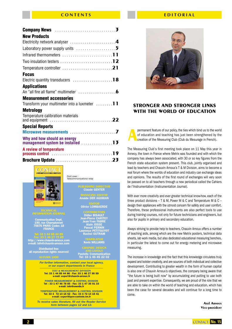
STRONGER AND STRONGER LINKSWITH THE WORLD OF EDUCATION
Apermanent feature of our policy, the ties which bind us to the worldof education and teaching has just been strengthened by the creation of the Measuring Club (Club du Mesurage in French).
The Measuring Club's first meeting took place on 11 May this year inAnnecy, the town in France where Metrix was founded and with which thecompany has always been associated, with 30 or so key figures from theFrench state education system present. This club, jointly organised andlead by teachers and Chauvin Arnoux’s T & M Division, aims to become areal forum where the worlds of education and industry can exchange ideasand opinions. The results of the first round of exchanges will very soonbe passed on to all teachers through a new periodical called the Cahiersde l'Instrumentation (Instrumentation Journal).
With ever more creativity and ever greater technical know-how, each of thethree product divisions – T & M, Power M & C and Temperature M & C –design their appliances with the utmost concern for safety and user comfort.Therefore, these professional instruments are also perfect tools to useduring training courses, not only for future technicians and engineers, butalso for pupils in primary and secondary education.
Always striving to provide help to teachers, Chauvin Arnoux offers a numberof teaching aids, among which are the new Metrix posters, technical datasheets, lab work media, but also dedicated educational measuring benches,in particular the latest to come out for energy metering and microwavemeasuring.
The increase in knowledge and the fact that this knowledge circulates trulyexpand and bolster creativity, and are sources of both individual and collectivedevelopment. Contributing to greater wealth in the form of human capitalis also one of Chauvin Arnoux’s objectives, the company being aware that"the future is being built now" by accumulating and putting to use bothpast and present expertise. Consequently, we are proud of the role that weare able to take on within the world of teaching and education, which hasbeen the case for several decades and will continue for a long time tocome.
Axel ArnouxVice-president
2 No. 15CONTACTCONTACT
C O N T E N T S
PUBLISHING DIRECTORClaude GENTER
MANAGING EDITORAnaïde DER AGOBIAN
EDITOROlivier LOMBAERDE
CONTRIBUTORSDidier BISAULT
Jean-Pierre CARITEYJean-Yves FABRE
Alain JOSSEPascal PERNIN
Laurence PETITGUYOTRachel OUTRAM
TRANSLATORKevin WILLIAMS
GRAPHIC DESIGN AND LAYOUT
Pastelle CommunicationTel: 33 1 45 45 22 02
Front cover :Telecommunications relay
TECHNICAL INFORMATION JOURNAL
Communication Dept.190, rue Championnet
75876 PARIS Cedex 18FRANCE
Tel: 33 1 44 85 44 85Fax: 33 1 46 27 73 89
http://www.chauvin-arnoux.come-mail: [email protected]
Distributed free all reproduction rights reserved
AUTUMN 2000
Company News . . . . . . . . . . . . . . . . . . . . . . . . . . . . .3New ProductsElectricity network analyser . . . . . . . . . . . . . . . . . . . . . .4Laboratory power supply units . . . . . . . . . . . . . . . . . . .5Infrared thermometers . . . . . . . . . . . . . . . . . . . . . . . .11Two insulation testers . . . . . . . . . . . . . . . . . . . . . . . . .12Temperature controller . . . . . . . . . . . . . . . . . . . . . . . .21FocusElectric quantity transducers . . . . . . . . . . . . . . . . . . .18ApplicationsAn “all fire all flame” multimeter . . . . . . . . . . . . . . . . . .6Measurement accessoriesTransform your multimeter into a luxmeter . . . . . . . .11MetrologyTemperature calibration materials and equipment . . . . . . . . . . . . . . . . . . . . . . . . . . . . . .22Special ReportsMicrowave measurements . . . . . . . . . . . . . . . . . . . . . .7Why and how should an energy management system be installed . . . . . . . . . . . . . . .13A review of temperature process control . . . . . . . . . . . . . . . . . . . . . . . . . . . . .19Brochure Update . . . . . . . . . . . . . . . . . . . . . . . . . . .23
E D I T O R I A L
For further information, contact your local agency,or our export departments in France
TEST & MEASUREMENT DIVISIONTel: 33 1 44 85 44 86 - Fax: 33 1 46 27 95 59
e-mail: [email protected]
POWER MEASUREMENT & CONTROL DIVISIONTel : 33 1 47 46 78 85 - Fax: 33 1 47 35 01 33
e-mail: [email protected]
TEMPERATURE MEASUREMENT & CONTROL DIVISIONTel: 33 4 72 14 15 52 - Fax: 33 4 72 14 15 41
e-mail: [email protected]
To receive sales literature, fill out the Reader Service form between pages 12 and 13.

3No. 15 CONTACTCONTACT
C O M P A N Y N E W S
At the beginning of this year, the ElectromagneticCompatibility (EMC) test laboratory on thepremises of our site in Annecy, France, wasawarded an accreditation by the Testing Sectionof the French Accreditation Committee (COFRAC)numbered 1-1036.
This accreditation covers most immunity and emission tests currently required for marking incompliance with the following generic standards:
EMC accredited by the COFRAC
Ever y 2 years, in March, Birmingham is the venue of one of the most impor tant Brit ish exhibit ions in the f ield of electricity: Electrex. Chauvin Arnoux won renown during this year'sshow with a 50m2 stand and by taking part in the “Products ofImagination Awards” - a competition where prizes are awardedto the best products exhibited, and which could be described asa “prize for innovation”. Among the 64 products nominated, 12were selected from the different fields linked to electricity (i.e.connectors, relays, etc.) and only 3 were awarded prizes inthe measurements sector.A prize was, once again, awarded to Chauvin Arnoux. Thistime, it was the megohmmeter C.A 6525 (photo opposite)which hit the jackpot. Proof that, as regards insulation moni-toring, there is general agreement as to the quality of Chauvin Arnoux’sinstruments.
A medal in England
Should anyone wish to meet us...During the second half of this year, we will be taking part in the professional trade fairs and exhibitionsshown below. An ideal time for listening and conversing, we will be happy to show you our very latestinnovations and get your opinions in person.
24/10 - 28/10 MATELEC Madrid - Spain
07/11 - 11/11 BIAS Milan - Italy
21/11 - 24/11 ELECTRONICA Munich - Germany
22/11 - 26/11 EDUCATEC Paris Porte-de-Versailles - France
11/12 - 15/12 ELEC Paris-Nord Villepinte - France
Trimaran 2 approved
Manumesure in BelgiumManumesure, the group's service company,is continuing to expand outside metropolitanFrance. In June of this year, it opened a newagency in Brussels, and it is Mr Patrice Vigneronwho is in charge of running the agency.Covering all of Belgium, this new structure will in particular be responsible for housing the group's after-sales service, as well as repairing,calibrating and carrying out maintenance work onprofessional electrical equipment of all brands.
Mr Patrice Vigneron
Manumesure BrusselsAvenue Van Volxem 176 - 178
1190 Brussels 19BELGIUM
Tel: 32 23 44 84 39Fax: 32 23 44 87 92
NF EN 50081-1 of June 1992 NF EN 50081-2 of December 1993 NF EN 50082-1 of January 1998 NF EN 50082-2 of June 1995The test laboratory in Annecy carries out thoseelectromagnetic compatibility tests which arenecessary for developing new Metrix and ChauvinArnoux brand appliances.
It is with much satisfaction that Chauvin Arnouxhas received approval for the Trimaran 2, our newenergy meter, from the Centre of Technical andElectrical Expertise belonging to EDF-GDFServices (EGS - French national electricity andgas companies). The meter is currently beingdisplayed in all EGS's regional centres.Designed to meet the new requirements of theEDF's industrial customers, Trimaran 2 makesimplementation of the "Tarif Vert Émeraude"(Emerald Green Rate) possible, and offersa number of other possibilities.One of the principle innovations of Trimaran 2,the ‘prism concept’, consists in dissociating the
meter itself from the tariff application. In otherwords, a Trimaran 2 meter is not fast-set in itspossible uses and in the changes that can bemade to it. Likewise, this principle makes itpossible to offer a product suited to theglobalisation of markets since it is open to alltariff changes. This product, available all over theworld, is known as a Prismeter – the Trimaran 2being specific to the EDF.
Reader service No. 1

4 No. 15CONTACTCONTACT
If you were looking for an appliance that is simpleto use, user-friendly and capable of the best in
terms of network analysis, in short an all-terrainand exceptionally gifted appliance, look no further!You have found it! Here is the first complete touch-type interface three-phase analyser (see box forthe list of parameters measured).
An abundance of functionsBuilt into a sturdy casing suitable for a buildingsite, the C.A 8350 is designed to be used out inthe "theatre of operations". The safety terminal, onthe right-hand side of the appliance, makes itpossible to connect the different voltage andcurrent leads (5 A direct input, 1,200 A clampsensors or even 3,000 A AmpFLEX) and the powersupply cable. On the front panel, there is no switch to disconcertthe user. Only a potentiometer allows the displaycontrast to be adjusted. The sober appearance ofthis face makes the lavish user interface standout. As soon as the appliance is started up, andat any moment, all the functions available aredisplayed right at the bottom of the screen: General configuration Input connection and parameterisation Harmonic Analysis Oscilloscope mode (photo 1) Vector graphics (photo 2) Energy and power monitoring Flicker rate measurement Voltage monitoring EN 50160 summary chart Transients recording Data logging
Simple and safe to useUsing this device is exceptionally intuitive. All programming and reading is carried out simplyvia the touch screen, within the user-friendlycontext of the Windows‘ operating system. To thisend, a USB connector allows both a keyboard anda mouse to be connected. Data is stored in the
internal memory and offers 6 months of autonomy.The software (delivered with the appliance, as isthe USB cable) makes it possible to generate andedit reports on data analysed in chosen timewindows in the language one chooses (English,French, German, Italian or Spanish). As far assafety is concerned, the C.A 8350 also offers thebest level of conformity with the IEC 61010-1 600Vcat. III standard.
And open-ended!The basic configuration automatically includes theFFT analysis functions and oscilloscope mode. Theother functions can be obtained as optional extraswhen the purchasing order is placed, or they couldpossibly be added later on as an open-ended requirementof the user. By the way, on the subjectof it being "open-ended", we have not yetmentioned that the C.A 8350 is designed torespond to the needs of tomorrow and the dayafter: there will be no problem in adapting it tofuture standards in the field of electricity networkquality. As we said, it is an exceptionally giftedappliance!
Network analysis at the tip of a light penEfficient and brand new, the C.A 8350 is a touch screen-type electricitynetwork quality analyser, whose power and user-friendliness are similarto that of a portable computer. The latest in Chauvin Arnoux’s range ofpower and interference testers, the C.A 8350 has already received the bestpossible reception from a technically highly specialised and particularly demanding client group.
Parameters measured
Voltage and current - Actual and average effective values- Peak value and peak factor
Power - Total active power and active power of the fundamental
- Total reactive power and reactive power ofthe fundamental
- Apparent power and power factor- Harmonics: current, voltage, active and reactive power, and reactive distortion power
Harmonic breakdown to the 50th order- Voltage: measurement of absolute Hn and of Hn / fundamental
- Current: measurement of absolute Hn and of Hn / fundamental
- Phase shift of each harmonic- Overall and order-by-order THD (total rate of Hn distortion)
- Recognition of the direction of eachharmonic order
Spectral analysis of inter-harmonic frequencies- Active, reactive and apparent power- System with positive phase sequencecomponent, negative phase sequencecomponent and zero-sequence component
- Phase shift- Absolute value of voltage and current for thecomplete spectrum
- Voltage and current vector graphics
Flicker- Measurements in compliance with EN 60868, EN 61000-3 and IEC 60868:
Short (Pst) and long-term (Plt) flickermeasurementAverage flicker on each phaseMax. instantaneous flicker
HV network analysis- “Short-circuit” events recording (fault recorder)
- Voltage symmetry- Power and frequency oscillation
And the whole analysis according to EN 50160
N E W P R O D U C T
2.Vector graphics:Voltage, current and harmonics.Automatic scale, connection and phase
direction check, summary of measurements
Reader service No. 2
1. 8 trace oscilloscope4 voltages and 4 currents
automatic activation, automatic scaling
5No. 15 CONTACTCONTACT
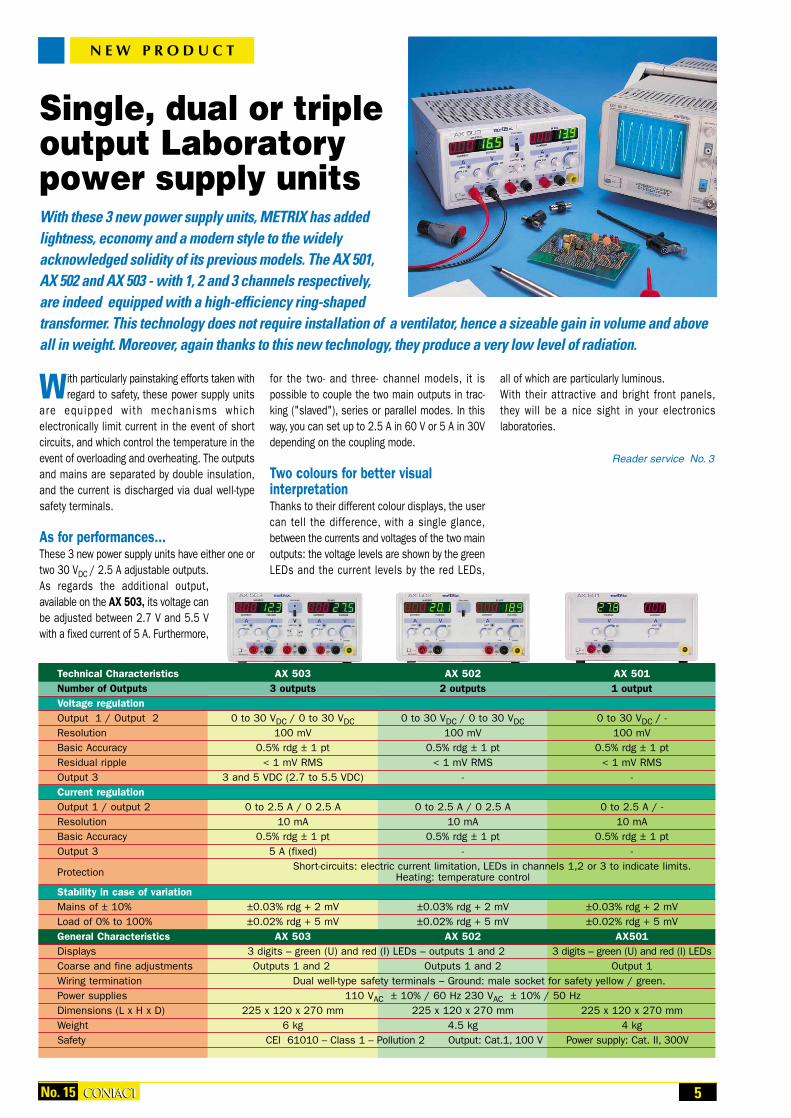
With particularly painstaking efforts taken withregard to safety, these power supply units
are equipped with mechanisms whichelectronically limit current in the event of shortcircuits, and which control the temperature in theevent of overloading and overheating. The outputsand mains are separated by double insulation,and the current is discharged via dual well-typesafety terminals.
As for performances...These 3 new power supply units have either one ortwo 30 VDC / 2.5 A adjustable outputs.As regards the additional output,available on the AX 503, its voltage canbe adjusted between 2.7 V and 5.5 Vwith a fixed current of 5 A. Furthermore,
for the two- and three- channel models, it ispossible to couple the two main outputs in trac-king ("slaved"), series or parallel modes. In thisway, you can set up to 2.5 A in 60 V or 5 A in 30Vdepending on the coupling mode.
Two colours for better visual interpretationThanks to their different colour displays, the usercan tell the difference, with a single glance,between the currents and voltages of the two mainoutputs: the voltage levels are shown by the greenLEDs and the current levels by the red LEDs,
all of which are particularly luminous.With their attractive and bright front panels,they will be a nice sight in your electronics laboratories.
Reader service No. 3
N E W P R O D U C T
Single, dual or tripleoutput Laboratorypower supply units With these 3 new power supply units, METRIX has added lightness, economy and a modern style to the widely acknowledged solidity of its previous models. The AX 501, AX 502 and AX 503 - with 1, 2 and 3 channels respectively, are indeed equipped with a high-efficiency ring-shaped transformer. This technology does not require installation of a ventilator, hence a sizeable gain in volume and aboveall in weight. Moreover, again thanks to this new technology, they produce a very low level of radiation.
Technical Characteristics AX 503 AX 502 AX 501Number of Outputs 3 outputs 2 outputs 1 outputVoltage regulationOutput 1 / Output 2 0 to 30 VDC / 0 to 30 VDC 0 to 30 VDC / 0 to 30 VDC 0 to 30 VDC / -Resolution 100 mV 100 mV 100 mVBasic Accuracy 0.5% rdg ± 1 pt 0.5% rdg ± 1 pt 0.5% rdg ± 1 ptResidual ripple < 1 mV RMS < 1 mV RMS < 1 mV RMSOutput 3 3 and 5 VDC (2.7 to 5.5 VDC) - -Current regulationOutput 1 / output 2 0 to 2.5 A / 0 2.5 A 0 to 2.5 A / 0 2.5 A 0 to 2.5 A / -Resolution 10 mA 10 mA 10 mABasic Accuracy 0.5% rdg ± 1 pt 0.5% rdg ± 1 pt 0.5% rdg ± 1 ptOutput 3 5 A (fixed) - -
Protection Short-circuits: electric current limitation, LEDs in channels 1,2 or 3 to indicate limits.Heating: temperature control
Stability in case of variationMains of ± 10% ±0.03% rdg + 2 mV ±0.03% rdg + 2 mV ±0.03% rdg + 2 mVLoad of 0% to 100% ±0.02% rdg + 5 mV ±0.02% rdg + 5 mV ±0.02% rdg + 5 mVGeneral Characteristics AX 503 AX 502 AX501Displays 3 digits – green (U) and red (I) LEDs – outputs 1 and 2 3 digits – green (U) and red (I) LEDsCoarse and fine adjustments Outputs 1 and 2 Outputs 1 and 2 Output 1Wiring termination Dual well-type safety terminals – Ground: male socket for safety yellow / green.Power supplies 110 VAC ± 10% / 60 Hz 230 VAC ± 10% / 50 HzDimensions (L x H x D) 225 x 120 x 270 mm 225 x 120 x 270 mm 225 x 120 x 270 mmWeight 6 kg 4.5 kg 4 kgSafety CEI 61010 – Class 1 – Pollution 2 Output: Cat.1, 100 V Power supply: Cat. II, 300V

6 No. 15CONTACTCONTACT
Specially developed to be used in climatic andenvironmental engineering, the C.A 5260
multimeter-cum-thermometer offers the best inmultimeter measuring. Robust and efficient, thisappliance has all the functions required for flametests as well as for use in measuring temperature,voltage, current, continuity, resistance, capacity,etc. In short, a real multimeter designed forprofessionals, to use "when things are gettingheated".Its compact casing means that it offers a perfectgrip and fits easily into your pocket. Handlingerrors are avoided due to the selection of thenominal ranges, which in this case is automatic.The large back-lit 4,000 count display is trulycomfortable for your eyes to read. Connected tothe flame detector of a gas-fired boiler, the C.A 5260 enables combustion level setting to befine-tuned (see box). Via its adapter for a K-typethermocouple (supplied with the appliance), theC.A 5260 also enables temperatures between–40 and +1,000°C to be measured. The temperatureis then read directly in °C or °F.
A P P L I C A T I O N
O t
An "all fire all flame"multimeter With the C.A 5260, the renowned Chauvin Arnoux C.A 5200 multimeter series is expandingagain. This time, the multimeter in question is a dedicated one, specially developed to be used in climatic and environmental engineering. Heating engineers and specialists, self-employed qualified plumbers, boiler installers, laboratory technicians and those in charge of maintenance in the field of climatic and environmental engineering will be the people principally concerned by this new tool.
Setting and adjusting the combustion level on
a gas-fired boiler by meansof an animating electrode
PrincipleIf a dipole formed by two electrodes with verydifferent surfaces is placed in an ionisedmedium, such as a flame, the system willbehave like a current rectifier. In that way,if this dipole is supplied with an alternatingvoltage, the circulating current becomesa single-alternation rectified current (see graph). Application of this principle in agas-fired boiler, with an amplifier controllinga relay, forms a device called a “flamerelay”.
HandlingSo, the C.A 5260, set to the µA DC measurement, should be connected to theflame detector and then an optimumcombustion level setting corresponding tothe maximum ionisation current should befine-tuned.
Owing to its numerous functions, the C.A 5260is both a multimeter and a thermometer,dedicated and at the same time multifunctional:voltage up to 600 V AC/DC, resistance up to 40MΩ, capacity up to 4,000 µF, continuity test, diodetest, min. and max. recording, HOLD key forkeeping the value displayed on the screen, and, ofcourse, compliance with the CEI 61010-1 CAT. III600 V safety standard.
Reader service No. 4

The rapid development of microwaves originated with radar. The latterwas developed in the USA during the Second World War for military
purposes, in order to locate the enemy plane squadrons as early as possible,and give them time to organise an effective defence. Today, microwaves areused in diverse and varied areas of activity. Here are the best-known: aeronautics, with radar and radio altimeter, telecommunications, with radio relay systems, cellular radiotelephony, with the mobile phone, security and safety, with alarms: detecting cases of overstepping
and volumetric protection the food-processing industry, with microwave heating trading, with measurement of the degree of moisture carried out
without the use of a contact element, a process also used in the pharmaceutical industry, the food industry and in food grain storage
level or distance measurements carried out without the use of a contact element are other recent industrial applications.
Frequency planeMicrowaves correspond to a frequency range lying between those frequenciesused by radio and those of infrared. They extend from about 300 MHz to approximately 300 GHz (see the diagram at the bottom of the page).What makes microwaves remarkable is the fact that the weak value of theirwavelengths (close to the visible spectrum), allows transmissions having a great degree of directivity to be achieved using rather small antennae.Therefore, beaming equipment is less sensitive to atmospheric or industrialinterference. The limited range of microwaves is also an advantage which iswidely used in cellular telephony (several distant relays use the samefrequency to transmit various emissions).
Standard constitution of a microwave systemA microwave system used in telecommunications is generally made up of the following main subassemblies a transmitter that generates the microwave energy needed to establish a
link, i.e. the information medium frequency and power necessary to attainthe desired range.
a connecting cable used to carry microwave energy produced bythe transmitter to...
an antenna, which will beam it.
The microwave energy will then be propagated into free space, thus carryingthe relevant information. At the other end of the information carrying chain,we generally find a symmetrical structure composed of: an antenna that will pick up the microwave information, then a connection cable which will carry it... to the receiver, which has to give back the relevant information (radarecho, digital or analog message, or otherwise an audible message such asone from a telephone, radio or television).
Why it is necessary to carry out measurementsWhy and when do we need to carry out measurements? As for any electronicsystem, the need to carry out measurements exists throughout the entirelife of a microwave system, from its conception through to its reversal, namely: when the product is being thought up, when the product is qualified, to check its compliance with the specifications, when it is installed on the site on which it will be operated, when it receives technical acceptance, then for the whole of its operating life as part of normal maintenance
procedure.
S P E C I A L R E P O R T
Microwave measurementsOmnipresent, microwaves are a part of our technological everyday life. With theexception of a few experts, they are, however, little known to many of us. Becauseof this, we deemed it necessary to write a special report on the subject. What is amicrowave system, what quantities characterise it, and how do we measurethese quantities? We will attempt to give these questions simple answers, even ifit means being sometimes simplistic, in order to be understood by everybody.
Acoustics Radio and TV Microwaves Infrared Ultraviolet X rays Gamma rays
1 Hz
ELF VF VLF LF MF HF VHFUHF
SHFEHF
visible
3 kHz
300 kHz
300 MHz
300 GHz
30 THz
Antenna
Wiring termination
Coaxial connection
cable
Propagation
Pavble = available power at
antenna input
Transmitter (generator)
Pout = power at transmitter
outputReceiver
Wiring termination
Frequency plane
Standard diagram of a microwave system. Ideal scenario:Pavble = Pout (il y (there is maximum energy transfer)
7CONTACTCONTACTNo. 15

8 CONTACTCONTACT
What are the measurements to be carried out?In order to qualify a microwave system, depending on the circumstances,the following inspections will be performed: measurement of the power emitted by the generator measurement of the load's impedance matching (cable + antenna) measurement of the connecting cable's insertion loss fault location on the connecting cable measurement of the radiated electric field plot the geographical zone covered by the transmitter
Power metering In order to check the compliance of a transmitter, we are led to measure thepower that it provides. We can assess this by one of two methods.
A. Measurement by insertion.This method consists in inserting - in series, then - a measurement instrumentin the form of a wattmeter or a wattmeter-cum-reflectometer between thetransmitter output and its load circuit (cable, antenna). A directional couplerdraws a portion of the energy circulating between the transmitter and itsload. A detector is then used to deliver a voltage proportional to the powerdetected; this voltage and the coupling value make it possible to deducethe exact value of the power measured.B. End point measurementThis second method consists in connecting a milliwattmeter, coupled to a transducer in which the power supplied will be dissipated, to the generatoroutput in place of the load circuit. Two types are generally used: the diodetransducer and the thermoelectric sensor. In both these cases, the sensoris used as a load adapted to the end point of the measurement line.a). The diode transducer detects amplitude by supplying a voltage proportionalto the amplitude of the microwave signal to be measured; this voltage isthen used to calculate the value of the power measuredb). The thermoelectric sensor supplies a data item which is proportional tothe average power dissipated in the form of temperature in the load. Two variants coexist: The microwave thermistor, generally used in a branch of a Wheatstonebridge. The microwave power that is dissipated in the thermistor causes achange in its resistance which then unbalances the Wheatstone bridge. Withthe resistance variation of the thermistor being proportional to the averagepower to be measured, the information concerning the unbalance of theWheatstone bridge is used to determine the value of this power. The thermistor used here is a very small component;its diameter is around 0.2 mm and its connectingwires around 20 µm. The microwave thermocouple, superposing twodistinct functions. Firstly, a film which is resistiveto the matched impedance and in which the power tobe measured is dissipated, causing the temperature torise. Then a thin film thermo-couple superposed onto this load
resistor, whose rise in temperature it measures, and which delivers a voltageproportional to the power to be measured. The microwave thermocouple isa component made of thin coats of metal that are in the region of a fewhundred angströms thick.
Adaptation measurementIn any microwave system, it is of paramount importance to ensure that theload circuit produced by the generator actually has an impedance which isadapted to the impedance of the generator output. It is the essential requirement for there to be maximum energy transfer between the generatorand the load circuit. This problem, which conditions the device’s performance,has a direct effect on the operating costs.In the field of microwaves, when a load circuit is not adapted, implying whenits impedance does not correspond to the “conjugate impedance” of thegenerator, part of the energy produced by the generator is lost by reflectionon the load impedance. The energy reflected by the load will disseminate intothe transmission link, from the load to the generator, and meet the energyproduced (called incident) and which disseminates in the opposite direction.These two energies, coming from the same generator, are coherent, and willtherefore heterodyne and give rise to a “standing wave”, made up of a succession of maxima and minima corresponding to the distributioncomposition in phase or in antiphase along the line of these two energies.The standing wave thus produced is characteristic of a level of impedancemismatch between generator and load circuit.We are therefore naturally induced to carry out measurements on this standing wave in order to qualify the degree of impedance mismatch, whichamounts to assessing the system's performance. The instruments usedhere are the wattmeter-cum-reflectometer, analyser or scalar tester.
A. Reflection coefficientWe qualify impedance mismatches by the Voltage Reflection Coefficient,symbolised by the letter gamma, which corresponds to the ratio betweenthe reflected voltage and the incidental voltage: Γv = Vr / ViIt can also be expressed in terms of power Γv = √(Pr / Pi) where Pr and Piare respectively the reflected and incidental powers. Γv is between 0 and 1Γ is often expressed in dB: Γ(dB) = 20 log Γv, in particular by the Anglo-Saxons, to whom it is known as “Return loss“ (reflection loss).
B. The SWRThe other essential measurement consists in determining the Standing WaveRatio, abbreviated to SWR, whose value is between 1 et ∞.If Vi and Vr represent respectively the incidental voltage and the reflectedvoltage, by definition, the SWR is given by the following equation: SWR = (Vi + Vr) / (Vi – Vr)The SWR can also be expressed based on the reflection coefficient: SWR = (1 + Γv) / (1 - Γv)
A few orders of magnitude
SWR = 1.05 Very goodSWR = 1.20 AcceptableSWR ≥ 2 Poor
Insertion LossWhen we want to qualify a piece of microwave telecommunications equipment, it is worthwhile making sure that the connecting cable betweenthe transmitter (or the receiver) and the associated antenna is in perfectcondition, and that it will not prevent the transmission of energy. You mustmake sure that the cable does not generate a too considerable “InsertionLoss", out of consideration for the principle of “maximum energy transfer”.As its name indicates, the Insertion Loss is a loss, a dissipation of the
S P E C I A L R E P O R T
Thin-film microwave thermocouple.Actual diameter: approx. 30 mm.
Transmitter (generator) Receiver
Impedance matching
Beamed electric fieldGeographical cover
Impedance matching
Power emitted
Power available
Inse
rtio
n lo
ssFa
ult
loca
ted
Inse
rtio
n lo
ssFa
ult
loca
ted
Qualification of a microwave system
No. 15

transmitted produced energy, by insertion of the component concerned – inthis case the connecting cable – between the generator and its use.The equipment destined to carry out this measurement (milliwattmeter orscalar tester) proceed by comparison between the energy injected into theinput of the cable to be tested and the energy available at the output.If Pout is the power injected into the input of the cable under scrutiny andthe Pavble is the power available at the other end of the same cable, then the Insertion Loss, symbolised by IL and measured in dB, is given by thefollowing equation: PI(dB) = 10 log (Pavble / Pout) (see block diagram on thefirst page of this article).For a given cable, the value of the Insertion Loss is, of course, proportionalto its length; for example, if it is 0.2 dB for 1 m, then it will attain 20 dB for 100 m.
Locating a fault on a cablePart of the microwave telecommunication installation is nearly always locatedoutside, and this is often the case with coaxial connecting cables. This equipment, subject to attacks from external agents such as temperaturevariations, humidity, abnormal mechanic stress, etc., can become defectivein the following ways: oxidation of the contact elements of a connector crushing of a cable, poor contact between the outer cable conductor and the connector connector short-circuited, etc.
These different defects cause microwave signal transmission between thegenerator and the device radiating the signal to be impaired and interruptedare caused by the deterioration or interference of the microwave transmissionsignal, between generator and user, therefore causing major transmissionfailures. Now, these connecting cables which connect the transmitter to thetransmitting antenna, or the reception antenna to the receiver, are often verylong, because the antennae are generally placed on roofs or at the top of apole several dozen meters high. It is, therefore, advisable to have a toolcapable of locating the possible fault on the path of the cable to be tested.The standard instrument for these measurements is a fault locator; a function which the scalar tester also has.Two measurement methods make it possible to locate a fault on the path of a coaxial cable with a known characteristic impedance. Both of them usethe same characteristic physical features concerning the dissemination of microwave signals in the lines: the phase differences undergone by themicrowave signals during their “forward-backward” journey passage alongthe length of a transmission line, varies depending on the frequency used.
A. Step method.This first method consists in injecting an excessively steep voltage step intothe input of the cable being tested, i.e. with a very short equivalent build-up time;then in analysing the echo, i.e. the signal available on the return. The signalreflected by the cable's impedance discontinuity corresponds to the stepemitted transformed by the impedance irregularity and the propagation time.However, this measurement method, which has the advantage of being quick,requires a subtle interpretation, and offers a mediocre measurement resolution.
B. Frequency response.This second method corresponds to the reflection coefficient frequencyresponse measurement of the cable to be tested, a frequency responsecharacteristic of the nature and position of the faults on the cable path. An algorithm, based onthe “Inverse FourierTransform” calculation,makes it possible toaccurately determinethe position, in termsof distance, of theimpedance discontinuitysought.
Electric field measurementThe effective signal is remote transmitted thanks to propagation of the electromagnetic wave beamed by the antenna. It is worthwhile checking the validity of this propagation, to make sure that this link in the data transmission chain, between the transmitter and the receiver is not interrupted; for example by spurious reflections or by a blockage in thepropagation.It is also important to be able to check that an appliance does not radiatedue to a too-high energy level, so as not to adversely affect the neighbouringelectrical equipment (electromagnetic compatibility).These measurements are carried out by electric field measurers. Their principle is based on the use of a great broadband reception antennacombined with a detector that delivers a voltage proportional to the electricfield picked up. However, these instruments, which offer the advantage ofworking on a very broad frequency band, have the inconvenience of notknowing the frequency value of the signal measured.
Electric field coverageTo determine the geographical zone covered by a transmitter, e.g. in order toforecast by simulation the reach of the calls expected to be made, the extentof GSM cellular radiotelephony coverage, we are led to map out the electricfield around this transmitter. The equipment destined to carry out this measurement has to be very sensitive and enable a measurement to becarried out at a pre-determined frequency without being disrupted by thoseelectric fields available on other frequencies.The equipment intended to carry out this type of function are selective receivers, with several frequency changes, using the frequency-movable“Measurement Window ” technique; a technique used in spectral analysis.These measurement receivers have, in addition to their capacity to carry outselective frequency measurements, a very great level dynamic measuringrange, and a very high degree of sensitivity. It is fairly common to have asensitivity in the region of –120 to –130 dBm, meaning that these receiversare capable of measuring signals in the region of 1fW (10-15 W)!
S P E C I A L R E P O R T
Antennae at a terrestrial radio relay station
9CONTACTCONTACT
This cable shows a serious defect at 26 m from the outlet as well as twolesser defects at 20 m and 22 m, corresponding to connectors (measurement
carried out using an ORITEL RO600 scalar tester)
No. 15

10 CONTACTCONTACT
S P E C I A L R E P O R T
Microwaves: our measurement solutionsAll the different qualifying parameters in a microwave system, as those we have presented to you to on thepreceding pages, can be measured with the appliances making up the “microwave” range of Chauvin Arnoux’s Test and Measurement Division.
The Corresponding Measurement InstrumentsThe following table presents Chauvin Arnoux’s measuring instruments that cover these types of measurement.
Computer processing of dataThe C.A 43, C.A 47 and ORITEL RO600 can be usedwith software allowing measurements to be processedand archived on a microcomputer. These softwarepackages are now available for use in a WindowsTM
95, 98 or NT environment.
ORITEL MH600 milliwattmeter Power measurements are carried outby the ORITEL MH600 milliwattmeterthat covers a frequency range of 100 kHz to 50 GHz, with a dynamicmeasuring range of 100 pW to a few W depending on the associatedmeasuring probe.Reader service No. 5
ORITEL RW500 series wattmeters-cum-relectometers High power levels are measured usingthe wattmeters-cum-reflectometers inthe ORITEL RW500 series. They produceincident and reflected powers of up to1 KW between 2MHz and 2.7 GHzdepending on the model; they also allowadaptations to be qualified.Reader service No. 6
ORITEL RO600 Scalar Tester The ORITEL RO600 Scalar Tester, a field apparatus, measures theadaptation (SWR) and the insertion loss of a quadripole between 1 MHzand 2.7 GHz. This instrument also accurately locates the position of a fault corresponding to an impedance discontinuity on the path of acoaxial connecting cable.Reader service No. 7
C.A 41 and C.A 43 field measurers The C.A 41 and C.A 43 field measurers, combined withtheir EF1 and EF2 probes, measure an electric field ina very extensive frequency domain: from 1MHz to 3 GHz.Reader service No. 8
C.A 47 RF receiver For its part, the C.A 47 RFselective receiver measuresthe electric field picked up byan antenna, at any frequencychosen between 25 MHz and2.5 GHz, on a very widedynamic range extending from100 µW / -10 dBm to 0.1 fW/ -130 dBm.Reader service No. 9
Power Impedance Insertion Fault Electric FieldInsertion Limit Adaptation Loss Location Radiation Coverage
ORITEL MH600 with associated coupler with associated coupler
ORITEL RO600
ORITEL RW with associated load
C.A 41/C.A 43
C.A 47 With accessories
No. 15

11No. 15 CONTACTCONTACT
Our human perception of good or bad lightingis quantified using a luxmeter, an instrument
which measures illumination, i.e. the quantity oflight received by a unit area. Illumination isassessed in lux (symbol lx). For example,under French regulations, theminimum lighting power for adraughtsman's work station isset at 300 lx. The AFNOR X35-103 standard lays down theprinciples concerning the user'svisual comfort which are to beapplied with regard to lighting in thework place. For more information on thissubject, we suggest you read issue No. 46 of the Contact Measurement News magazine (French version - article available onlyin French).
A ‘top of the range’ cellThe C.A 808 cell is designed around a
selenium sensor (more sensitive thansilicon), the spectral and spatial
responses of which are corrected inaccordance with the curve of "the
international mean eye" set up bythe International Lighting
Committee. Capable ofmeasuring up to 20,000lx, it gives out a signal
which is proportional to thelighting measured, at the rate
of 1 mV for 100 lx. Thanks to its 2meter-long shielded cord, it can easily
be connected to all digital multimeters (2,000counts minimum, rating 200 mVDC) via two Ø 4mm banana plugs.
Some very practical detailsUnder the casing, a KODAK pitch-threaded insertenables it to be mounted on a tripod. Furthermore,an elastomer captive cover ensures the protectionof the sensitive surface while it is in storage orbeing transported. When it is being used, the cellalready has a protection rating 54 level of dustand watertightness.Delivered either by itself as an accessory or in acomplete fitted-out carrying case along with a multimeter and cords, the C.A 808 cell is areliable, precise and sensitive instrument, intendedfor professionals who are very demanding whenit comes to the accuracy of their lighting measurements.
Reader service No. 10
M E A S U R E M E N T A C C E S S O R I E S
Transform your digital multimeter into a precision luxmeterWork regulations and quality standards applicable to the building industry define the minimum lighting levelsrequired on public and business premises, as well as in all types of housing and accommodation. The instrumentsrequired for these measurements are luxmeters of high quality, accurate and reliable, but fairly expensive. At a lesser cost, the C.A 808 luxmetric cell enables your digital multimeter to be transformed into a high-performanceand accurate luxmeter.
The user-comfort advantage of the remotetemperature measuring gunAs ergonomic as an instrument can possibly be imagined, the new C.A 878 and 880 infrared thermometers offer, in addition, measurement performances that will surprise you.
Professional appl iances for precision measurements, the C.A 878 and C.A 880
thermometers astonish with their prowess. Their“gun”-shaped casing makes them exceptionallyeasy to handle and gives them an extraordinarydegree of user comfort. All functions (min, max,average, ∆T, emissivity and auto-hold) can be triggered using just one hand. The disengageabletrigger can be locked in order to carry out measurements by scanning the target (scannerfunction). The laser sight, available on the C.A880, offers perfect handling flexibility for aimingat the dead centre of any target whatsoever, with
no possible error. The rapid response time (300 ms), wide measurement range ( -32°C to +500°C),adjustable emissivity (20% to 100%) and automatic back lighting are as many extra assetswhich make these thermometers essential tools.
The diameter of the surface targeteddepends on how away far it is. The closer you getto the target, the smaller the surface is and themore accurate the measurement. This "distancefrom target / diameter of surface targeted" ratiois also called the measuring range. It has theshape of an elongated cone, with a diameter of10 cm at a distance of 1m, and doubles with eachmeter (though this is only an approximation,chosen because it is easy to remember).
N E W P R O D U C T
Reader service No. 11

12 No. 15CONTACTCONTACT
N E W P R O D U C T
Two new references for insulation testingSpecialists in electrical safety measuring instruments, Chauvin Arnouxoffer a new generation of insulation testers in a casing tailored for operations in the field. At the leading edge as regards technology and functionalities, these appliances have immediately begun to stand out as the new references in insulation testing at between 50V and 1kV.
Controlled by a microprocessor, the C.A 6541and C.A 6543 megohmmeters have very
advanced functions for measuring insulation (up to 4 TΩ), AC/DC voltage (1,000 V), continuity(40Ω, with a current > 200 mA up to 20 Ω),resistance (400 kΩ) and capacity (5 µF).
The C.A 6543 model also has a rechargeablebattery and a built-in charger, a memory of 128Kbytes, a RS232 connection allowing the applianceto be controlled entirely from a PC and making itpossible to transfer data for computer processingby a specially developed software package (withdisplay of the isolation trend curves, etc.)
The insulation expertsAmong the many innovative functions whichthese new testers have, we can mention thefollowing:
Automatic calculation of the Pl and DARcoefficients (see box)
So as not to be subject to the influence of parasiticcurrents which might pervert the insulation measurement, for example while testing arotating machine, measurements must be carriedout over a long period of time. The insulation valueobserved and recorded once the measurementhas been performed, as well as those of the Pland DAR coefficients (irrespective of temperature),make it easier to judge the intrinsic quality of theinsulants.
Programme test durationInsulation measurements sometimes take a goodwhile to level off. Being able to perform measurementsover a more or less long period of time and analysethe insulation trend curve according to the lengthof time the test voltage is applied leads to a betterappreciation of the qualities of the different insulants.
R(t) curves plottingThe user himself chooses the sampling rate atwhich the insulation measurements will be stored.These values will then be used for plotting theinsulation trend curve depending on the length oftime the test voltage is applied. With the"MEGOHM VIEW" software package for the
C.A 6543, this profile is directly plotted on the PCscreen. Complete control of the appliance from a PC:starting and stopping measurements, storingresults, setting limits, etc.
Blocking access to the insulation test voltages(so as to be able to entrust the appliance to lessqualified people).
Programmable alarms
Smoothing of measurements for display
Remote triggering via the remote control probe.
... and still many more that you will discover eachtime you use these high-performance products.
Reminders of the polarisation index (PI) and the dielectric absorption ratio (DAR).
PI = R10’/R1’ DAR = R1’/R30’’ Insulation quality
PI < 1 ou 2 DAR < 1.25 insufficient, even dangerous
2 < PI < 4 1.25 < DAR < 1.6 satisfactory
PI > 4 DAR > 1.6 excellent
For further information, we suggest you read the special report in Contact Measurement News No. 14.
Reader service No. 12

Industries, for whom energy expenditure represents between 15% and 50%of production costs, have a crucial need to know WHERE, WHEN, HOW and
HOW MUCH energy is used. Moreover, the recent deregulation of the electricalenergy market necessitates having accurate energy assessments in order to freely choose one's energy supplier on the basis of this specific andunquestionable data. Indeed, the choice of the best price scale is the customer's responsibility, for he is the only one who can know the possiblerise or fall, in real time, of his requirements. Energy management systems meetthis double requirement. There are now economic and open-ended solutions,suited to the most modest companies' budgets, and the cost of which will,moreover, very quickly be recouped through the savings made.
Aims and principleThe aims of global and automated energy management are to make (director indirect) profits and/or implement a system of consumption managementby analysis (cross-charging, breakdown per cost centre). The possible savings“reservoirs” can be of different kinds (reducing the energy bill, controllingthe costs on products lacking in quality, preventive maintenance, awarenessof energy expenditure, etc.). The advantage of energy management is to beable to quantify these “reservoirs”. In order to do this, the operator must implement the following essential functions: Measurement of electrical values. Metering of active and reactive energy, pulses (water, gas, steam etc),overshooting subscribed power, etc. History making it possible to analyse changes in expenditure withregard to forecasts, break down consumption per sector and quantifycorrective actions. Archive the events that have arisen on the network
(overshooting thresholds, extreme valuesreached, etc). Monitoring sensitive electrical values (power factor, harmonics, etc.). Detection of abnormal incidences(overintensity, overvoltage etc.).
An Energy Management System is usuallymade up of smart submeters connected to anindustrial local network. This network is usedto transmit all the metering information, whichwill be organised and saved in a database,over long distances. This database will thenbe used by an energy management softwarepackage to draw up statistics, repor ts,judicious and periodic assessments etc, thatare necessary to enable decisions to be madeand corrective action to be carried out.
The flexibility and adaptability of good energymanagement enable information to be circulated selectively to the different peoplemaking up the company. Each person receives
organised and directly usable data in personalised reports.
The stages of good energy managementAttaining these objectives requires implementation of a real energy management policy, as well as the introduction of a plan of action which isgenerally broken down into several phases (analysis – assessment – diagnosis / accomplishment – follow-up).
Analysis of requirementsThe implementation of submetering procedures requires, beforehand, that thefactory be split up into different parts according to functions. This split willestablish consumption sectors which are common to the whole factory(boiler/furnace room, compressed air station, cold units for air conditioning,etc.) and the specific sectors (workshop, assembly line, department, etc.).If necessary, each sector could be further split into modules, in order, forexample, to show up the share of the different operations involved in themanufacturing of a finished product. This analysis also applies to tertiaryindustry buildings, with the following sectors: offices, conference rooms, thestaff canteen, leaseholders, common services, etc.
AssessmentThis stage consists in accurately determining exactly where, when and howthe different energies are consumed, and how much. This assessment isdrawn up from the periodic recording of power requests (power profile). Theserecordings, archived and used by a specific software package, enable reports,assessments and graphs to be drawn up in order to know the exact powerrequested and the consumption.
S P E C I A L R E P O R T
Electrical Energy: why and how shoulda management system be installed?A significant improvement in energy expenditure necessarily requires a better knowledge and control of one'sconsumption profile. Overall and centralised energy management brings with it quantitative and qualitative information on consumption. Periodically or selectively, all this information is exploited by the users.
13CONTACTCONTACTNo. 15

Diagnosis and ActionTaking this energy assessment as a basis, those actions which are supposedto lead to energy savings are determined: renegotiation of the supply contract(version and power subscribed), installation of power cut-off mechanisms,capacitor batteries and anti-harmonics filters, modification of consumptionhabits, etc.An order of investment priorities can be set up based on this calculatedassessment.
Follow-upFollowing up the consumption records by means of an appropriatesoftware package is the only way to measure the savings made,to make them into long-term savings and to initiate others. Thisfollow-up will be daily, weekly, monthly and/or yearly, depending on therequirements expressed: monitoring excess demand, cross-chargingand adjusting the supply contract.
The advantages of an energy management systemThere are many advantages in installing an energy management system andthey are all very different. Principally, we can mention:
1. Automatic archiving of consumptionsThe automatic remote reading of meters brings speed, comfort and reliability. It avoids the necessity for repetitive and sometimes long routineinspections. All risk of error on the index readout is ruled out. Automaticdata archiving allows more time to be devoted to studying and optimisingconsumption.Recording the power profile of mean power levels, which makes it possibleto carry out an exact follow-up of consumption over the course of time andto detect overshoots of subscribed power, requires a large number of dataitems to be archived (e.g. 1,152 values over 8 days, 59,904 over a year in10-minute periods). Only an automatic remote reading of the information onthe meter makes this follow-up possible.
2. Technical and accounting analysis of consumptionThe periodic recording of consumption makes it possible: To draw up summary tables for each sector. These tables give an overallview of consumption in a factory, a company department, a production lineor a cost centre, breaking it down into tariff brackets and calculating over-shoots of subscribed power. The results will be expressed in energy units(kWh, kvarh, m3/h) or in monetary units (euros, francs etc.).
S P E C I A L R E P O R T
t1 t2 timet3
kWh current
∆E (t2-t1)
∆E (t3-t1)
∆E (t3-t2)Index No. 1
Index No. 2
Index No. 3
Type 1 trend
Type 2 trend
Method of energy consumption metering by index reading On a set date and at a set time, index reading, previously carried out by the routine inspectors, is automated.Time stamping enables consumption levels between two remote readings to be calculated.
The advantages: Simple method for energy metering
Little data to archive
Reduced traffic on the local communication network
All the indexes are read in a short time
No error possible in the remote reading of the index values
The disadvantages: The consumption profile between 2 index readings
(e.g. t1 and t2) is not known
No continuous monitoring of power intakes
Breaking consumption down into tariff brackets is tricky.
Example: power profile recording of power requests at a metering point (Winthor software)
Example: graphic display of the powers requested and the energyconsumed at one of the metering points (Winthor software)
14 CONTACTCONTACT No. 15

S P E C I A L R E P O R T
To draw up periodic energy assessments (daily, monthly, yearly, etc.) thatin turn enable rapid identification of the "greediest" consumption points. To rapidly identify the savings “reservoirs”, measure the influencethat changing the characteristics of the supply contract (type of tariff,subscribed power, etc.) might have, and quickly locate cases of abnormaloverconsumption. To establish significant energy ratios or indicators (e.g. the quantity ofelectricity, water, steam or gas consumed / quantity of manufactured product,kWh/m2, etc), in order to take into account the energy cost involved in manufacturing a finished product. Recording the power profiles enables the energy cost to be taken into account in the calculation of the ratios depending on the moment the power is consumed. To supply reliable data and accurate energy diagnoses in order to rapidlyestablish the return on investment by quantifying the energy gains obtained.This accurate data affords precious help when it comes to making any decision regarding investment (new machine, cogeneration, etc.). It can beproven, by means of results which are accurate and expressed in figures,that energy is being purchased at the best price.
3. Optimising the supply contractPossible courses of action as regards the supply contract and consumption: Decrease the total amount of the fixed premium by lowering thevalues of the subscribed powers. The fixed premium (or subscription) isproportional to the subscribed power. This premium often represents morethan 35% of the total bill. Analysis of the load curves and notably that ofthe billing meter (green meter) makes it possible to display quickly and clearlywhether or not the subscribed power is far beyond the power requests ofone's electricity network. Reduce overshoots of subscribed power. In France, the fixed subscriptionpremium is proportional to the subscribed power. Each overshoot of thispower is billed at top price. Recording the load curve enables any overshootto be displayed and quantified accurately. Analysing all the load curves indetail will show up the number of non-priority feeders to which power is likelyto be cut off. Decrease active energy consumption by transferring consumption tothe least expensive tariff periods. All the data supplied by the energy management system (load curve, overshoots, kWh per tariff bracket, etc.)contributes to getting the “kWh” at the lowest cost, transferring consumptionfrom peak time to day-tariff hours and from day-tariff hours to night-tariffhours. Decrease the reactive energy consumption by monitoring and controllingthe value of the tg ϕ.
4. Carrying out preventive maintenance on the network.Continuous analysis of all the events (tg ϕ, excess demands, extreme values,harmonics, abnormal consumption, etc.) reduces the number of critical interventions on the electricity network. Operating staff have accurate information in real time with which to optimise the use and increase the lifespan of the electricity network equipment.
Method of energy consumption meteringby load curve reading
The values of the mean power levels are calculated on the basis
of 15-minute consumption periods:
Pave (15’) = 4x∆E (15’).
This method enables the power request profile (kW requested
depending on time).
The advantages: Accurate identification (value, moment, cost) of the subscribed
power overshoots
Calculation of the influence of modifications made to supply
contract parameters
Calculation of the influence of corrective action on consumption
Determination of the "greediest" feeders and moments with
regard to energy consumption
Breakdown of consumption per sector or cost centre (analysis
management)
Breakdown of consumption per tariff bracket
The disadvantages: The quantity of data conveyed over the local network is
considerable
The number of data items to be archived and organised is bulky,
and necessitates the use of high-performance computer
equipment.
Energy consumed over a period of 15 mins.
Energy accumulation curve (kWh)
Subscribed powerAverage power over 15 minutes
Profile of power requests (kW)
∆E
∆t=15 min
t1 t2 time
Example: assessment showing, in figures, consumption at a given point of the site over two months (Winthor software)
15CONTACTCONTACTNo. 15
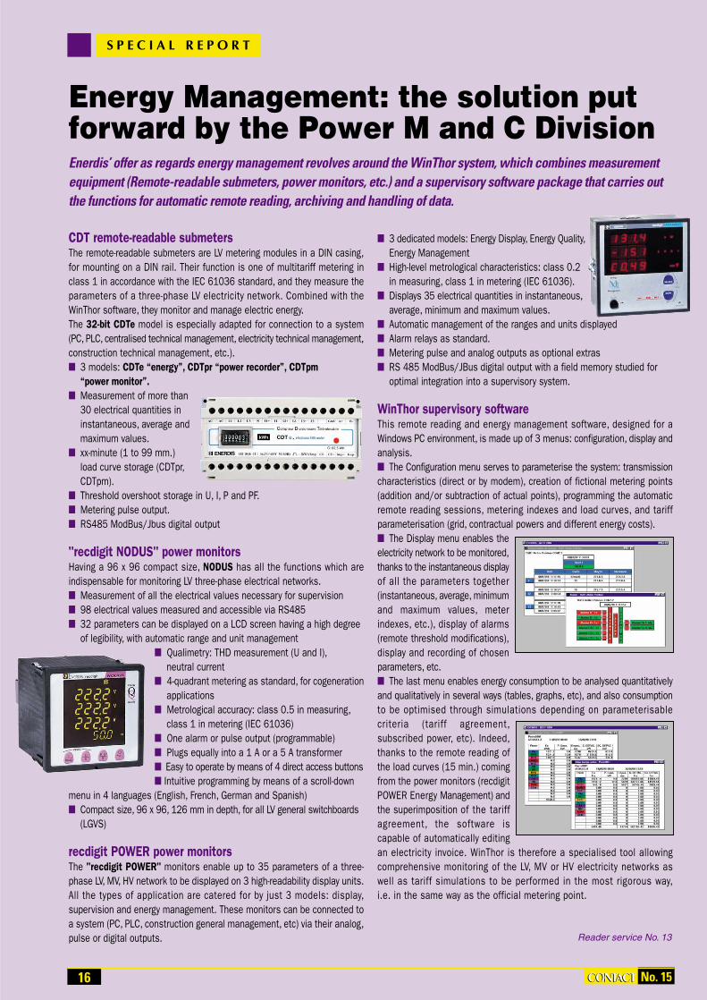
CDT remote-readable submeters The remote-readable submeters are LV metering modules in a DIN casing,for mounting on a DIN rail. Their function is one of multitariff metering inclass 1 in accordance with the IEC 61036 standard, and they measure theparameters of a three-phase LV electricity network. Combined with theWinThor software, they monitor and manage electric energy. The 32-bit CDTe model is especially adapted for connection to a system (PC, PLC, centralised technical management, electricity technical management,construction technical management, etc.). 3 models: CDTe “energy”, CDTpr “power recorder”, CDTpm
“power monitor”. Measurement of more than
30 electrical quantities ininstantaneous, average andmaximum values.
xx-minute (1 to 99 mm.)load curve storage (CDTpr,CDTpm).
Threshold overshoot storage in U, I, P and PF. Metering pulse output. RS485 ModBus/Jbus digital output
"recdigit NODUS" power monitors Having a 96 x 96 compact size, NODUS has all the functions which are indispensable for monitoring LV three-phase electrical networks. Measurement of all the electrical values necessary for supervision 98 electrical values measured and accessible via RS485 32 parameters can be displayed on a LCD screen having a high degree
of legibility, with automatic range and unit management Qualimetry: THD measurement (U and I),
neutral current 4-quadrant metering as standard, for cogeneration
applications Metrological accuracy: class 0.5 in measuring,
class 1 in metering (IEC 61036) One alarm or pulse output (programmable) Plugs equally into a 1 A or a 5 A transformer Easy to operate by means of 4 direct access buttons Intuitive programming by means of a scroll-down
menu in 4 languages (English, French, German and Spanish) Compact size, 96 x 96, 126 mm in depth, for all LV general switchboards
(LGVS)
recdigit POWER power monitors The "recdigit POWER" monitors enable up to 35 parameters of a three-phase LV, MV, HV network to be displayed on 3 high-readability display units.All the types of application are catered for by just 3 models: display,supervision and energy management. These monitors can be connected toa system (PC, PLC, construction general management, etc) via their analog,pulse or digital outputs.
3 dedicated models: Energy Display, Energy Quality,Energy Management
High-level metrological characteristics: class 0.2in measuring, class 1 in metering (IEC 61036).
Displays 35 electrical quantities in instantaneous,average, minimum and maximum values.
Automatic management of the ranges and units displayed Alarm relays as standard. Metering pulse and analog outputs as optional extras RS 485 ModBus/JBus digital output with a field memory studied for
optimal integration into a supervisory system.
WinThor supervisory softwareThis remote reading and energy management software, designed for aWindows PC environment, is made up of 3 menus: configuration, display andanalysis. The Configuration menu serves to parameterise the system: transmissioncharacteristics (direct or by modem), creation of fictional metering points(addition and/or subtraction of actual points), programming the automaticremote reading sessions, metering indexes and load curves, and tariff parameterisation (grid, contractual powers and different energy costs). The Display menu enables the electricity network to be monitored,thanks to the instantaneous display of all the parameters together (instantaneous, average, minimumand maximum values, meterindexes, etc.), display of alarms(remote threshold modifications),display and recording of chosenparameters, etc. The last menu enables energy consumption to be analysed quantitativelyand qualitatively in several ways (tables, graphs, etc), and also consumptionto be optimised through simulations depending on parameterisablecriteria (tariff agreement,subscribed power, etc). Indeed,thanks to the remote reading ofthe load curves (15 min.) comingfrom the power monitors (recdigitPOWER Energy Management) andthe superimposition of the tariffagreement, the software iscapable of automatically editingan electricity invoice. WinThor is therefore a specialised tool allowingcomprehensive monitoring of the LV, MV or HV electricity networks aswell as tariff simulations to be performed in the most rigorous way,i.e. in the same way as the official metering point.
Reader service No. 13
S P E C I A L R E P O R T
Energy Management: the solution putforward by the Power M and C DivisionEnerdis’ offer as regards energy management revolves around the WinThor system, which combines measurementequipment (Remote-readable submeters, power monitors, etc.) and a supervisory software package that carries outthe functions for automatic remote reading, archiving and handling of data.
16 CONTACTCONTACT No. 15

General power supply
Meter
Factory
LVGS No. 1 LVGS No. 2 LVGS No. 3
Field bus
JBus™/RS485
CDTe
CDTpr
Toptem
TRIMARAN 2
recdigitPOWER
CDTprCDTpr
recdigitPOWER
recdigitNODUS
recdigitNODUS
WinThor software
General services
Design office
Machine shop
Production line
Testing Department
Administrative building
S P E C I A L R E P O R T
The range of communicating products for energy metering and management offer suitable and open-ended solutions adapted and developed for all elec-tricity network monitoring as well as consumption control and optimisation applications. The whole of these products, connected to a field bus (RS485ModBus/JBus), makes an overall and point-by-point analysis of the electricity network possible. Associated software such as WinThor – allows energyassessments to be carried out, tariff agreements to be optimised through an analysis of consumption profiles, and detailed simulations to be performed.
17No. 15 CONTACTCONTACT

18 No. 15CONTACTCONTACT
By developing an ASIC containing all its knowledge, Enerdis has equipped its range of
TRIAD transducers with a digital measuring centre,the guarantee of an exceptional stability, with anaccuracy of class 0.2 and compliance with electromagnetic compatibility standards. This technology allows the user, on the one hand, toconvert “strong current” electric quantities to “lowlevel” signals with an isolation of 4 kV and aresponse time of less than 300 ms, and, on theother hand, to group up to three functions in asingle casing. On top of this, the ASIC hasimproved the product’s configuration flexibility
which can, in a very short space of time, beadapted precisely to the characteristics of theinstallation (input transformation ratios, measuringranges, transfer curves and output ranges). TRIADis an extremely economical answer in terms of thepurchasing and installation costs, especially sincethe programming can be done directly by thecustomer thanks to the TRIADJUST software. Thisrange complies with the IEC 60688 standard andthe European directives.
A range full of advantagesTRIAD comes in the shape of DIN casings, 60 or120 mm wide, which click on to a DIN rail or fixonto the back of a cabinet. It is connected directly
to the screw terminals with 6 mm2 cables.A single TRIAD transducer can replace one, twoor three traditional transducers. For the user, theresult is a gain on the overall purchasing price(reduced price for the appliance, reduced wiringand installation costs and a smaller number ofmeasurement transformers). Thus for example, inan MV/LV (average voltage, low voltage) cell, thereare three traditional transducers to supply remotemeasurements of electric quantities (active andreactive power and voltage) necessary in thecontext of MV network supervision. With TRIAD,a single transducer will suffice for this task.
The ASIC circuit, besides its programming flexibility,also works under severe conditions, (temperature,humidity, interference), while at the same timeguaranteeing a class 0.2 metrology (in accordancewith the IEC 60688 standard). It offers betterimmunity against conducted and radiated EMCdisturbances and, finally, does away with the needfor periodic calibration operations.The 0.2% accuracy and especially the 4 kV dielectricstrength between the input, auxiliary power supplyand output circuits, go towards making the electrical installations safer, just as they guaranteecompliance with the international standardsimposed by the major industries and electricitycompanies.
Each TRIAD is equipped with a switching powersupply offering a broad dynamic rating allowingeasy adaptation to the power supply values available on each site, in AC as in DC.
Configurable productsThe digital technology implemented in the heartof each TRIAD transducer enables it to be parameterised exactly to the requirements of eachuse. With the TRIADJUST configuration software,you can reduce even more the waiting period for,and the cost of, installation of your TRIADtransducers. Developed in order to simplify technological modifications during installation andto diminish the stocks of products assigned tomaintenance, TRIADJUST is a high-performancetool for configuring the parameters of the transducer range in WindowsTM how and as manytimes as you like. Equipped with a PC and theTRIADJUST module's infrared transmitter, you caninteract with your TRIADs perfectly safely andwithout any specific electrical connection. You canthus act on the configuration of the transducers atany moment, on any site, for example to modify acurrent ratio on a TRIAD installed in a generalswitchboard, or even to adapt a TRIAD to thecharacteristics of the MV/LV cell that you are scheduled to deliver next week. In short, withTRIADJUST, you can rapidly and indefinitely accessall the operating parameters of your transducers.Because it is so user-friendly, you can very easilymodify inputs, measuring ranges, outputs, etc. ofthe transducers you install. You can even edit thecharacteristics and wiring diagram labels of thetransducers parameterised in this way.
Reader service No. 14
F O C U S
TRIAD Electric quantities transducersThrough its privileged contact with engineers in the electrical and industrial sectors, Enerdis is continually involved in the development and optimisation of measurement converters. More than 30 years of experience in this area have given us an excellent awareness of the applications and knowledge required forrunning electrical installations. The fruit borne of this know-how, TRIAD was the first in the range of multifunctionaland configurable digital processing transducers, offering, what is more, an absolutely remarkable accuracy andlevel of isolation. Enerdis has obtained these performances notably by developing an ASIC integrated circuit, a trulyaccurate and reliable measuring centre, right in line with the reputation for quality and performance of the productsof the previous generation.
TRIAD solution
1 TRIAD T33 P, Q, Iclass 0.2 accuracy4 kV isolation
Traditional solution
1 P transducer1 Q transducer1 I transducer
8 9 10 11 12 13 14
5 6 7
1 2 3 4
TRANSDUCTEUR de MESURE
Classe de précision
Etendue de mesure
Courant nominal
Tension nominale
Sortie
Résistance de charge
Source auxiliaire
Schéma de branch.t
UAR 1210 B9520
0,5
0 - 132 V
50
0 - 10 mA
0 - 1
125 Vcc
2319501
A
V
V
Hz j :
N˚ de série N˚ d'identification
2318483 F
fabriqué en France

In “process control”, in the last ten years, many programmable controllerswith built-in control loops have been set up on the production line. For a long
time, we thought that the traditional switchboard controllers were doomed toslowly disappear. Now, in the last few months, we have once again beenseeing sales rise for the big manufacturers of this type of product. Do the functions that they offer today suffice to explain this phenomenon?
The principle of automatic controlLet us take the simple example of oven temperature control to define the key terms. The aim is to keep the oven’s temperature at 200°C by varyingthe electric current in a resistor.
The oven’s temperature is the controlled variable The temperature fixed at 200°C is the set point The regulator's output variable is the correcting variable
What is a controller?A controller is an automatic process control device which enables quality,comfort and safety to be improved, and energy consumption to be minimised. The controller permanently compares the divergence betweenthe controlled variable and the set point (which is called the measurement-set point divergence) and sends a signal aiming to offset it. The differentsorts of automatic control can be arranged into 4 large technological families: Electromechanics Pneumatics and hydraulics Analog electronics Digital electronicsThe choice of technology must be made strictly depending on the degreeof automatic control being sought and the cost-in-use, as well as thedynamic and static behaviour of the processes concerned.
ElectromechanicsAs a general rule, electromechanical controllers have only one function. Theyare suited to simple and standardised configurations. They convert a physical
quantity into a mechanical movement aiming primarily to activate an electrical contact.
Pneumatics and HydraulicsThis technology has the advantage of having a simple and quick element. Very often used in a dangerous environment, this type of controller enablesmotors, valves or cylinders to be actuated without any risk of sparks.
Analog electronicsThese controllers make it possible to carry out simple functions: detection,adjusting, displaying, and calculations. The forming of measuring chains is simplified by the standardisation of exchange signals. This technology can be bought at a very low cost.
Digital electronics This technology uses one or more microprocessors. It makes possiblecomplex calculations in very short spaces of time, data storage, and datatransmission via a field bus. The user-friendliness of the man-machine interface has become a determining factor.
Programmable controllersThis type of product, originally designed for complex algorithms and toband together automatic operations, has progressively integrated new functionalities, like for example the control loops (PID action).
What is a control mode?For control to be optimal - meaning accurate, quick, insensitive to interference, and therefore stable - the operating mode of the controlsystem has to be suited to the process. The automatic controller must notmake its presence felt! Different modes solve all the automatic functioning problems in the various installations, depending on their static anddynamic characteristics, as well as the action range.
Cascade controlThe cascade system brings two control loops into play, with the first loopacting on the second. Its role is to “boost” reaction to the different disturbances which generate poor-quality controls.
Hot and cold controlThis is a single loop system but with two mutually opposed actions centered on the same control set point. Each action possesses its own PIDparameterisation. Before the set point value is attained, the ‘heating’ actionis set in motion; beyond that, the ‘cooling action’ takes over.
Ratio controlThe controller calculates the ratio between two values measured at the input.This ratio is kept constant by the control loop. It is most frequently used inquantitative analysing processes.
A review of temperatureprocess controlSince the first temperature controller was manufactured by Chauvin Arnoux in 1934, the process control systems have developed considerably. Physical parameters which were still impossible to measure yesterday, are available todayat a reasonable cost. This article offers you a clear insight into the current functions of temperature controller.
S P E C I A L R E P O R T
Furnace
Thermocouple Furnace temperature display
Set point value display Heating element
19CONTACTCONTACTNo. 15

20 CONTACTCONTACT No. 15
Protected controlA second controller, functioning in on-off mode, protects the control loop byimposing a maximum temperature which should never be exceeded. This system provides a very high degree of safety for a very small cost.
“Feed forward” controlThe heating power calculated by the controller is corrected by another variable,for example the network fluctuation or the load variation due to the ageingof the heating elements. This function is sometimes integrated into powercontrollers equipped with well-made thyristors.
Which outputs for electronic controllers?On-off outputsThis is the simplest and best-known, frequently used for simple systemswhen regulating quality is not very important (electric convectors, liquid level,etc.). If the measurement is lower than the set point, the controller's outputis active, and vice versa. Oscillations of the controlled variable occur aroundthe set point which are more or less considerable depending on the system’sinertia, hence its use in systems that do not require much precision.
Modulated outputThe controller's output is modulated according to a fixed time period and a cyclic ratio (on/off) which will vary depending on a value calculated by thecontroller. The fixed time period will be a compromise between the wearoutof the power element and the inertia of the process.
Direct current outputThe controller's output varies proportionally to the calculated value,generally got from a PID unit. The weaker the measurement-set point divergence, the weaker the output signal. It is useless when the controlledvariable is equivalent to the set point.
What are control parameters?These enable the controllers to calculate the actions to be carried out inorder to correct the divergences between the measurements and the set point.The PIDThis is the combination and complementarity of the following 3 actions: Proportional: it suppresses the oscillations in the process at a value
specific to it. Integrated: this corrective action adapts the speed of the controlling
element so as to offset the measurement-set point divergence. Derivative: functions together with the integrated action. It is useful
in cases of rapid and sudden disruptions in the process, and it cancelsitself out when the divergence is once again close to zero.
All these actions are known as PID and are defined by: The user, according to the process which is to be controlled. The Self-controlling algorithm: the PID is automatically controlled
by the controller, with the procedure being launched by the user.
The Self-adaptive algorithm: the PID is adjusted to the process witheach measurement-set point divergence observed by the controller. This is a dynamic function.
Fuzzy logicThis algorithm calls on the “fuzzy” concept, which brings in subjective notionsintended to be similar to human reasoning, for example: very cold, cold,warm, hot, very hot.It is associated with the PID. This new hybrid system enables mathematicalrigour to be combined with the flexibility of fuzzy logic.
What is the situation as regards the temperature controllermarket?As mentioned above, during the last few years we have observed an increasein demand for switchboard controllers, to the detriment of industrial programmable controller PID boards. How can we analyse this?The following 2 points will begin to provide an explanation.1. Control by programmable controller will never be as fine as with an automatic control, into which development teams have integrated all theirprofessional know-how on the subject of control. Today, a precision of ±1°Cis not easily achieved by a programmable controller, even one which is verysophisticated.. 2. Industries which use continuous process manufacturing represent amature market. Today, everybody is very aware of the place of each link in thechain and confusions are extremely rare. The tendency is to decentraliseequipment, interlinking closely by means of field buses. The programmablecontroller has its place within the perspective of an integrated system,managing complex algorithms and controlling separate elements. In theevent of a short “crash”, these elements have to continue autonomously tomonitor and control, to avoid production being destroyed. Thanks to that,the production teams will always be able to regain control in manual mode.This is why, in the Temperature M and C Division, we think that the futurein industrial process applications lies in independent controllers controlledby a system or a programmable controller.
Developments to Chauvin Arnoux’s rangeYear after year, the range expands with new products, which enables you tocontinually improve the quality of your controlling for a more and more modestproduct cost. Before, we did not have a product in our catalogue whose setpoint could be controlled by a system (programmable controller, supervisorand set point generator). Today, it is done: to our great satisfaction, thisproduct has just come to life in our factories - the STATOP 4860.Among a great many other novel features, it enables the control set point tobe remote modified by: either a 4 - 20 mA or 0 - 10 V fine control mechanism or a digital fine control mechanism in ModBus (RTU protocol)
We invite you to turn the page to learn about it in more detail
S P E C I A L R E P O R T
SET POINTGENERATOR
°C
Furnace No. 3
Furnace No. 2
Furnace No. 1
PC or programmable controller via a 4/20 mA analogue input
PC or programmable controller via a MODBUS digital input
•
•
Furnace
Safety thermocouple
Regulation thermocouple
Furnace temperature display
Set point value display
Heating element Power contactor
Safety regulator
Maximum temperature

21No. 15 CONTACTCONTACT
As standard, the latest in the STATOP range is compatible with most of the control
applications used in thermal processes. A wordof reminder : by “process” we mean an uninterrupted industrial manufacturing process,like the production of glass, fibres, etc. Here, theslightest failure can bring the production chain toa complete halt, if not the entire factory. Thereforeit is important that all equipment should have thesafety mechanisms making it possible to offsetany incident with the least possible loss in produc-tion. The STATOP 4860 meets this requirement.But this product, one of the quickest on themarket, (10 measurements per second), also has: A new algorithm: self-adaptive Two PIDs which are interchangeable via
a logic input One factual input (logic) One load supervision input via a current
transformer Completely insulated analog outputs The possible configuration by an external
programming console (which makes itpossible to save a configuration by downloading and to duplicate it onto otherSTATOP 4860s).
A 20 V / 25 mA transmitter power supply
It is, therefore, a high-performance product, butone which is very simple to implement. No need tobe an automatic control expert! The STATOP4860s self-adjusting capability means that it canbe used without specialised knowledge. The appliance itself determines the most suitableparameters for the process and automaticallyapplies them. During the control operation,the self-adaptation capability continuously corrects the PID parameters. And fuzzy logic contributes to the remarkable control stability.
Three inputsThe main input, for measuring the temperature orthe controlled variable, is configurable: it acceptsa number of different types of thermocouple,platinum probes and process signals, in voltageor current, coming from converters or programmablecontrollers (table 1). When parameterising, the
user will only have to indicate the signal used and,if need be, define a more restricted measuring range.
Table 1: input type 1
One of the numerous assets of the STATOP 4860,and not one of the lesser ones, is found in itsauxiliary input for process signals (table 2). This input allows analog remote control of thecontrol set points or reading of a current comingfrom a current transformer (ct) to 1 A secondary.In this way, for example, load break detection canbe monitored.
Lastly, a third input, this time logic, permits theconfiguration to be modified during process: choiceof another set point defined beforehand, alarmcut-off or selection of a second group of PID controlparameters.It is even possible to act on one of the controloutputs. This logic input is controlled at a very lowsafety voltage (VLSV): between –10 and +1 V are
seen as “0” logic, and the “1” corresponds to avoltage between 2 and 10 V.
Alarm or hot-cold outputs?As standard, the STATOP 4860 is equipped with two independent alarm relays. Entirely configurable (absolute alarm, deviation,symmetrical, time switch, suppressed at the firstdefault latch and hold functions, etc), they can beadjusted over the whole measuring scale.But the second alarm output can also be assignedto cold channel in the event of the “Hot-Cold”algorithm being chosen. Depending on the installation and heating element, you would choose-at the console- a logic or otherwise an analogueoutput, following the example of the first controloutput, which will then become the hot channel.
RS485 ModBus communicationWith the RS485 digital transmission option, theSTATOP 4860 easily lends itself to the running ofa supervised network in RTU ModBus protocol,with a turnover of 38.4 kbd. It will then be possibleto record the measurements, direct the set points,cut off alarms, etc with standard software whichcan be bought from a shop.Like the other DIN 48x48 models in the STATOPrange (4849 and 4850), the 4860 enables a rampto be introduced for temperature build-up, a timingfunction coupled to the alarms, and it is onlyslightly deep, which makes it easier for it to berecessed: only 75 mm.It is, on the other hand, the only one of the threeto have a power supply for transmitters (25 mA -20 VDC) and a programming menus access whichis protected by microswitches.The appliance is equipped with two 10,000-countLED displays, a red one to display the temperaturemeasured, and a green one for the set point. Thetemperature values can be parameterised anddisplayed in degrees Celsius as well as inFahrenheit. The power supply accepts from 90 to261 VAC, but the product can also be ordered in amixed VLSV version: 11 to 26 VAC or VDC.
Reader service No. 15
N E W P R O D U C T
A controller tailor-made for process applicationsWith its set point input remote-controllable via an analog or digital link, its self-adjustment and self-adaptation functions as well as its two PID loops, the STATOP 4860 temperature controller is perfectly suited to industrial processapplications. All the more so because its small DIN 48x48 format casing is totally impervious to dust and spraying with water (protection rating 65).
Input Maximum scale Accuracy
ct J -120 to 1000°C ± 2°C
ct K -200 to 1370°C ± 2°C
ct T -250 to 400°C ± 2°C
ct E -100 to 900°C ± 2°C
ct B 200 to 1820°C ± 2°C
ct R 0 to 1767.8°C ± 2°C
ct S -250 to 1300°C ± 2°C
ct N -250 to 1300°C ± 2°C
ct L -200 to 900°C ± 2°C
Pt100 DIN -210 to 700°C ± 0.1°C
mV -8 to 70 mV ± 0.01 mV
mA -3 to 27 mA ± 0.005 mA
V -1.3 to 11.5 V ± 0.0015 V
Input Scale Accuracy
ct …/1A 0 to 50.0 A ± 2%
mA -3 to 27mA ±0.005 mA
V -1.3 to 11.5 V ±0.0015 V
Table 2: input type 2

22 No. 15CONTACTCONTACT
Two methods are commonly used to calibratetemperature sensors: the comparison method
and the fixed-points method. It is not always easyto choose between the two of them. When it is great accuracy that one is looking for,let us say equal to or more than 0.01°C forinstance, then the fixed-points method is necessary.When there are a large number of sensors to bestudied, or if there is a greater tolerance regardingaccuracy, then the comparison method ispreferable. However, even in this case, having oneor several fixed-points enables reference sensorsto be periodically checked and indicates when theyneed to undergo a complete re-calibration.
The Comparison MethodCalibrating a sensor by comparison consists inplacing it in an enclosure whose uniform andconstant temperature is measured by means of astandard sensor, taken as a reference.
This method has several advantages because itallows you to: Calibrate a large number of sensors
simultaneously, Calibrate sensors having geometrically varied
shapes, Calibrate at different temperatures.However, it is often difficult to be sure that thesensors to be calibrated and the reference sensorare at the same temperature. Stable and uniformenclosures are difficult to achieve, especially at high temperatures, and the accuracy of theresults is directly linked to the calibration andstability of the reference sensor.Pyro-Contrôle Chauvin Arnoux manufacturesreference thermocouples and a surface sensorcalibrator device under licence from the BNM-LNE. (BNM: French National Metrology Office -LNE: French National Testing Laboratory)
Fixed-points methodCalibrating a sensor using the fixed-points methodconsists in placing it in an enclosure whoseuniform and constant temperature is defined bythe thermodynamic equilibrium between differentphases of a pure substance.Principle: A pure metal melts and solidifies at atemperature which is specific to that metal. Whenthe environmental temperature conditions arecorrect and the quantity of metal used is sufficient, the latent heat absorbed or releasedduring the change of phase maintains the metalmass, confined in the fixed-point cell, as well as thethermometer inserted into the well of the cell, ata constant temperature for several hours.
The main advantage of this method is that itprovides a highly accurate calibration at a knowntemperature with great precision (accuracy in the region of a mK), without being reliant on thecharacteristics of a reference sensor, which arelikely to drift with time. Let us not forget that thismethod is used for the International TemperatureScale (ITS-90).The limitations of this method are: Calibration can only be performed at a certain
number of pre-determined temperatures. During a change of phase, the number of
sensors to be calibrated is limited dependingon the duration of the temperature level.
The sensors to be calibrated cannot havejust any shape and configuration.
Reader service No. 16
M E T R O L O G Y
Calibration materialsand provisionsManufacturing products for - and supplying products to - industry, Pyro-Contrôle Chauvin Arnoux has a laboratory for calibrating temperaturesensors and manufactures different calibration appliances and systems:standard sensors, fixed-point cells and calibration furnaces and baths.
Fixed-point cell Temperature
Gallium +29.7646°C
Indium +156.5985°C
Tin +231.928°C
Zinc +419.527°C
Aluminium +660.323°C
Silver +961.78°C
Gallium triple point: +29.7646°C. Imperviouscell, closed in an argon atmosphere and fitted
with a valve for achieving the triple point.Manufactured under licence from INM-BNM.
C. Le
Toq
uin
/ S
tudi
o Ph
oto
CN
AM
Pyro-Contrôle Chauvin Arnoux developscomplete assemblies designed to achieve theITS-90 fixed reference points. The sealed cellsare manufactured under licence from the BNM-INM (INM = French National Metrology Institute).
The Pyro-Contrôle Chauvin Arnoux laboratoryis accredited by the COFRAC - No. 2-1385 for
calibration by comparison from -20°C to +1,550°C
Principle of a fixed-point cell

METRIX latest editionOn 32 colour pages, discover theessential products making up theMetrix ranges. Presented in tables indicating their main characteristics,appliances of the same type can easilybe compared. Selecting a product takesno more than a few minutes. From themoment you know the name of theappliance, a name index also makesresearch easier.
B R O C H U R E U P D AT E
Multimeters that areequal to anything
From the building site to the laboratory,Chauvin Arnoux's 5200 digital multimeterseries offers you the maximum in safetyand comfort. From 2,000 counts to as highas 40,000 for the most accurate model(0.1% TRMS), their pocket size, combinedwith the shockproof sheath, provides aperfect handgrip.
Temperature controlproblems overcome
Comletely electronic, the thyristor-equippedstatic power relays and regulators in the THYRITOP range guarantee a rapid and accurate load commutation, single- orthree-phase, from 25 A to 1.9 kA. These12 pages are richly illustrated.
Make your choicewith the worldleader!The amperemetr ic c lamp that you are looking for is inevitably in theChauvin Arnoux catalogue. Here is a guidebook that summarises the characteristics of all the models to choosefrom. An impressive choice at that!
Insulation in thepalm of your handIn this document, you will discover the complete range of Chauvin Arnouxinsulation testers in a user-friendly casing: 3 appliances dedicated to electrical instal lat ions and equipment and 2 dedicated to low currents: telecommu-nications signals, electronics, home automation, etc.
144 x 144 mm power monitors
The 3 Recdigit POWER power monitorsoffer a graded solution to the requirementsof LV, MV, HV network users: measurement(class 0.2) and display, monitoring and qualimetry, energy analyses. Thepowers (P, Q, and S) are measured ininstantaneous, maximum or averagevalues over a programmable length oftime. Load curves and event storage (min.,max., threshold) are other strong pointsof these communicating products.
All you need toknow about your
low voltage networkWith the NODUS power monitor by Enerdis,dissect in minute detail up to 98 parametersof your electrical network. Measure, display,consult at a distance, keep a track on yourenergy consumption/production, monitorharmonic distortion and the current circulating in the neutral. A very high-performance product, having a small format(96 x 96), with a remarkably well developedinterface for easy use. It is worth getting toknow it by reading this brochure.
All for one and onefor four“Because 80% of signals are periodic,analogue display remains the referencetype”. There is no denying that this quotedeserved to be backed up by a specificand complete documentation. That nowexists with this new 4-page brochurewhich portrays the whole Metrix analogoscilloscope range. Whether you work inthe field of video technology, teaching orindustry, you will find 1001 reasons forgoing analog.
Reader service No. 19 Reader service No. 20
Reader service No. 21 Reader service No. 22
Reader service No. 23 Reader service No. 24
Reader Service No.17 Reader service No. 18
23CONTACTCONTACTNo. 15

We have the industrialanswer to your electricalmeasurement needs
The electrician’s profession has become more and morecomplex as a result of an increasingly technological environment. So whether it’s test, control or generalinstrumentation equipment that you need, our distributionnetwork brings our expertise straight to you. All of whichhelps you to go about your business, whether it’s in installation, maintenance...
Electrical Installation TesterC.A 6115Test electrical safety with a single instrument
MegohmmetersC.A 6521/23/25
Insulation measurements have never been so easy
Clamp-on power and harmonic meterF27Analyse quality of electrical networkswith ease
Clamp-on earth resistance testersC.A 6410/12/15
Test earth loop resistance in a flash,from 0.1 Ω upwards
Metrix MultimetersMX Concept SeriesNeed a TRMS multimeter?A straightforward low-cost instrument?Then choose !
Differential input oscilloscopes OX 8062/8042/832/822Are you sure your measurements are earthed? Got a single reference potential for both channels? Happy with just 5 V/div? Better think differential oscilloscopes
Maintenance industrielleMaintenance industrielle
Industrial maintenance
Mantenimiento industrial
Manutenzione industriale
Industrielle Wartung
Manutenzione industrialeIndustrial maintenance
Industrielle Wartung
Mantenimiento industrial
The best in measurement
Test & Measurement Division190, Rue Championnet - 75876 PARIS Cedex 18 - France
Tél. : 33 1 44 85 44 86 - Fax : 33 1 46 27 73 89http://www.chauvin-arnoux.com
Call us now for details !
Rea
der
ser
vice
No
.25