no obstructions no paddle wheel no electrodes - keyenceno paddle wheel no electrodes ... to monitor...
TRANSCRIPT

No ObstructionsNo Paddle WheelNo Electrodes
Introducing the KEYENCE FD-M Series Flow Sensor
NEW Non-Wetted ElectrodeElectromagnetic Flow Sensors
FD-M Series
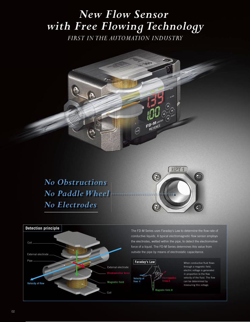
New Flow Sensor with Free Flowing Technology
FIRST IN THE AUTOMATION INDUSTRY
When conductive fluid flows
through a magnetic field,
electric voltage is generated
in proportion to the flow
velocity of the fluid. The flow
can be determined by
measuring this voltage.
Electromotive force: E
Velocity of flow: V
Magnetic field: B
Coil
Detection principleThe FD-M Series uses Faraday's Law to determine the flow rate of
conductive liquids. A typical electromagnetic flow sensor employs
the electrodes, wetted within the pipe, to detect the electromotive
force of a liquid. The FD-M Series determines this value from
outside the pipe by means of electrostatic capacitance.
Faraday's Law
Coil
Velocity of flow
Electromotive force
Magnetic field
External electrode
External electrode
Pipe
No ObstructionsNo Paddle WheelNo Electrodes
• • • • • • • • • • • • • • • • • • • • • • • • • • • • • • • • • • •
02

NPT 3/8(10A)Display range: 0.14 - 7.50 G/min (0.50 - 30 L/min)
NPT 3/4(20A)Display range: 0.7 - 26.4 G/min (2.5 - 100 L/min)
NPT 1(25A)Display range: 1.4 - 52.8 G/min (5.0 - 200 L/min)
Data collection
Alarm output indicator
Select and toggle buttons
PC
Programmable logiccontroller
Flow value display
Threshold value
Flow indicators
SUS430
Dual output
03
4-20mA Scaleable

Using conventional technology...
Float/Area Type Flow Meter
<Principle> <Principle>
Paddle Wheel/Turbine/Gear Type Flow Meter
As time passes...
As liquid enters the bottom of the tube, the float begins to rise. The position of the float varies directly with the flow rate. Its exact position rests at the point where the differential pressure between the upper and lower surfaces balance the weight of the float.
Units consists of a multiple-bladed rotor, obstruction mounted, within a pipe. The rotor spins as the liquid passes the blades. The rotational speed is a direct function of flow rate and can be sensed by a magnetic pick-up, photoelectric cell, or gears.
04
bottomtomom ofofof thththeee tub
i l
• Contamination requires disassembly for maintenance
• Poor visibility• Clogging due to
the deposit of slurry/sludge
• Clogging due to the deposit of slurry/sludge• Axle/bearing wear• Contamination requires
disassembly for maintenance
Unstable flow control
Temperature fluctuation
Increased process variation
Decreased quality control
W i t h t h e
W i t h t h e

2. Quality improvement
3. Maintenance free
NO OBSTRUCTIONNo pressure loss. Reduces the load on pumps and saves energy.
NO PADDLE WHEELNo moving parts. Maintenance free.
NO ELECTRODESNo errors due to buildup. Maintain accurate flow control from outside the pipe.
05
Detection from outside of the flowing pipe.
Detection with wetted electrodes
Three advantagesto reach the goal of flow management
K E Y E N C E F D - M
K E Y E N C E F D - M
1. Productivity enhancement
The FD-M Series with Free Flowing Technology
Resistant to deposits
The FD-M Series with Free Flowing Technology
Conventional flow sensor
Stable detection, even with deposits of 19.69 Mil (500 µm)
Generates an error with deposit of 0.39 Mil (10µm)
Generates an error when the electrodes are covered with deposits.
Stable detection even though the measurement area is covered with deposits.
The FD-M Series withFree Flowing TechnologyConventional flow sensor
Free-flowing pipe
*Comparison of FD-M with a KEYENCE conventional sensor
Resistance test to insulating material
Flow examination is done with deposits on the electrode or the measurement component.

The FD-M Series is used in such manufacturing fields as:
06
Powertrain components
Typical manufacturing equipment
Die cast machine
Forging machine
Deburring machine
...........P08
Automotive interior/exterior parts
Typical manufacturing equipment
Molding machine
Paint
Assembly machine
............P12
Automotive tires
Typical manufacturing equipment
Molding machine
Vulcanizing process
............P12

07
Cutting, grinding, quenching and powder casting products
Typical manufacturing equipment
Cutting or grinding machine
Quenching
Welding machine
...........P10
......................P14
............P14
Electronic and precision molded parts
Typical manufacturing equipment
Molding machine
Washer
Assembly machine
............P12
............................P14
Others
Typical manufacturing equipment
Molding machine
Washer
............P12
............................P14

For Diecast Machines
08
Die cooling Die lubricant coating
Application Study Vol.1
Flow control in diecast machines
Diecasting is widely used in the manufacturing industry as an efficient and economical process for producing high quality metal components. However, recovery after defects are produced or damage to the tooling occurs is both time consuming and expensive. If the temperature of the die is too hot or too cold, defects such as blowholes, sink marks, hot tearing, or bubbles can occur. Flow control is necessary in order to manage the die temperature and prevent these types of defects. Also, the critical application of die lubricant can be monitored and controlled by a flow sensor.
Heat-resistant FD-M sensors are ideal for diecasting applications where hot cooling water is used.
The importance of flow control in die lubricant applications
Cooling water lines used for die temperature control can become blocked due to their thin and complex design. Since cooling liquid flow is closely related to die temperature, flow control is critical to ensure that proper temperatures are maintained. The Diecasting process involves high temperature and therefore the cooling liquids themselves frequently reach extreme temperatures. The KEYENCE FD-M is designed for this environment with a temperature rating of up to 85˚C (185˚F).
Efficient utilization of die lubricants in the casting process can extend the life of dies and contribute to enhanced product quality. These lubricants will protect the surface from considerable temperature peaks that occur when the molten metal enters the die cavity. Also, fluctuations in die lubricant can cause temperature related quality issues and products to become stuck in the die after cooling. Therefore, the amount of lubricant used during the application process is a critical variable in die casting. This variable can be controlled with the addition of a KEYENCE FD-M flow sensor to your die lubricant spraying system.

Reduced Costs!
$3,000 USD
09
Die damage
E x a m p l e o f r u n n i n g c o s t s
1 piece 1 time
Number of occurrences per year
Machine downtime
3 hours 1 time
Number of occurrences per year Productivity
$1,000 USD
Conventional: Flow control using float type meters may not eliminate poor part
quality or machine damage due to insufficient cooling as a result of fluid
contamination or clogged pipes.
KEYENCE FD-M: The free-flowing pipe configuration eliminates downtime and
damage to dies due to clogging.
Strategies for cost reductionBoosting profit by reducing maintenance costs
$5,500 USD
Diecast machines use water for various cooling purposes. Fluctuations in the flow of cooling water within the die may result in damaged product or machine components due to increased temperatures and uneven cooling.

10
Flow control in grinding and polishing
Some polishing applications involve micron-level machining, which requires that a variety of conditions be controlled. Of these conditions, an important element is coolant flow control. The main objective of coolant flow is temperature control, which serves to reduce heat generated during grinding. Too little coolant can lead to defects, grinding wheel damage, and dimensional errors due to thermal expansion, while too much coolant can cause defects due to grinding wheel slippage.
Flow control
When the fluid flow is too low
Ceramic and CBN grinding wheels
Grinding machines that use CBN grinding wheels require extremely thorough flow control. Once the process has begun, grinding machines cannot be quickly stopped, so a fluctuation in flow of even a few liters can result in significant profile changes up to several microns. To improve product quality, it is necessary to monitor machine operations to ensure that coolant flow remains within the prescribed range.Conventional flow technology can be affected by contamination in the cooling process. The KEYENCE FD-M was designed to eliminate this concern with its Free Flowing Technology. Another concern may be the cost of grinding wheels. Products such as CBN Wheels can deteriorate due to excessive heat in the grinding process. With replacement costs of several thousand dollars, the addition of reliable flow control can be easily justified.
Foreign materials, sludge and abrasion grains are not properly rinsed from the part, resulting in flaws on the surface.
The fluid forms a layer between the grindstone and the workpiece, resulting in uneven surface roughness.
Grinding wheel cooling
For Grinding Machines
When the fluid flow is too high
Application Study Vol.2
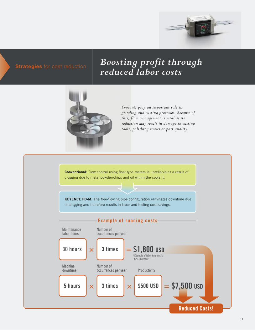
Strategies for cost reductionBoosting profit through reduced labor costs
11
Coolants play an important role in grinding and cutting processes. Because of this, flow management is vital as its reduction may result in damage to cutting tools, polishing stones or part quality.
Maintenance labor hours
E x a m p l e o f r u n n i n g c o s t s
30 hours 3 times
Number of occurrences per year
Machine downtime
5 hours
Reduced Costs!
3 times
Number of occurrences per year Productivity
*Example of labor hour costs: $20 USD/hour
$500 USD
Conventional: Flow control using float type meters is unreliable as a result of
clogging due to metal powder/chips and oil within the coolant.
KEYENCE FD-M: The free-flowing pipe configuration eliminates downtime due
to clogging and therefore results in labor and tooling cost savings.
$7,500 USD
$1,800 USD

12
Flow control in injection molding machines
Production operating times for molded plastic products is long and production volumes are subject to machine capacity. Injection molding machines are almost completely automated, so defective products can mean the difference between a profit or a loss. In many cases, temperature is the deciding factor behind quality. Flow control of cooling fluids has a significant affect on temperature control. Since the injection molding process involves rapidly heating and cooling plastics, the key is to completely control variables associated with temperature.
Optimum temperature in plastic molding machines
Variations in mold temperature can lead to sink marks, short shots, cracks, and other defects. Keeping the mold as close as possible to the optimum temperature is very important. Flow control is the most important factor in controlling this variable.Because plastic molding machines generally operate on long cycles, maximum daily production volume is based on machine capacity. If downtime is a result of defective products or mechanical issues, production cannot resume until the mold temperature is stabilized.
Restarting the molding process while the temperature of the mold is still unstable will produce products that are defective. It generally takes about two hours of waiting time until production can be resumed, resulting in huge losses. Due to this lengthy recovery time, temperature related downtime can lead to production schedules not being met. A single problem can be the difference between a profit or a loss. Reliable flow control can be used to avoid this risk.
Mold cooling Hopper gate cooling
Hopper gate cooling is required in factories with fully automated production.
For Injection Molding MachinesApplication Study Vol.3

Strategies for cost reductionCost reduction through reduced maintenance labor hours
13
Injection molding machines use water for cooling of multiple components. Unstable cooling flow to the mold may have an adverse effect on product quality due to uneven cooling, while insufficient cooling at the hopper gate may damage the materials in the hopper.
Maintenance labor hours
E x a m p l e o f r u n n i n g c o s t s
5 hours 2 times
Number of occurrences per year
30
Number of machines
Machine downtime
5 hours 1 time
Number of occurrences per year Productivity
$500 USD
Conventional: Flow control using paddle wheel type meters requires regularly
scheduled maintenance and downtime to prevent clogging cause by contamination.
KEYENCE FD-M: The free-flowing pipe configuration maintains stable flow and
eliminates downtime costs due to sensor maintenance. Product quality and
productivity remain high due to stable, uninhibited operation.
Reduced Costs!
$2,500 USD
$6,000 USD*Example of labor hour costs: $20 USD/hour

For Induction Hardening Machines
14
Flow control in induction hardening machines
For the stable control of cooling water for high-frequency hardening
Metal is hardened by wrapping it in a coil of copper wire to which a high-frequency AC current is applied (induction heating). This method inherently generates large amounts of heat in the coil and oscillating tubes, which can cause equipment damage if not cooled. Many of the components that can be damaged are typically very expensive and have long delivery times. Furthermore, if the product is not properly cooled, the desired degree of hardness will not be produced, resulting in the manufacture of defective products.
Welding machine Baking furnace
Processing machine
Washer
Other machinery

Features of the FD-M Series
15
Protected housing: IP65The IP65 housing allows the FD-M to be used in harsh environments.
Switchable flow directionThe flow direction can be switched by using the mode setting; you can mount the flow sensor at any location that can provide easy-to-view monitoring.
Use in low conductivity liquid applications as low as 5µS/cmLow conductivity liquids, such as purified or deionized water, can be measured as low as 5µS/cm.
Allows the FD-M to be used in high temperature cooling applications, such as recovered cooling water in forming machines or warming water in mold tools.
Dual digital display with easy setupDual colored digital display allows you to adjust setting values, while monitoring the present flow.
Output 2 indicatorOutput 1 indicator
Bank indicatorAlarm indicator
Present value indicatorSetting value indicatorSetup indicator
Mode buttonSelect and toggle buttons
Flow indicatorIndicates the instantaneous flow. Two-color LED illuminates in conjunction with the ON/OFF state of output 1.
Use with high-temperature liquids up to 185˚F (85˚C)

Multiple OutputsAll FD-M Series models provide multiple outputs including dual discrete, 4-20mA, alarm and pulse outputs, eliminating the need to choose between different versions.
Modes and functions[F-1] Upper / lower limit setting mode [F-2] Window + Accumulated pulse mode [F-3] Accumulated flow mode
Output is provided for each upper and lower limit.
Bank switch function (for F-1 and F-2 only)With the bank input provided, the setting values in each mode can be switched to another bank set.
Indication switch function for instantaneous flow/accumulated flowYou can use the button to easily switch between the instantaneous and integrating flows.
Peak and bottom hold functionYou can use the button to easily switch between the peak-hold and bottom-hold indication.
Two values can be set for the accumulated value.Output is provided for the set range. Pulse output is provided depending on the selected amount.
[A-1] Flow level mode [A-2] Accumulated flow + Timeout mode Free range analogTwo windows can be set at the same time. Unless output 1 turns on within the timer setting
period, output 2 (timeout output) will turn on.Output is provided with 4-20 mA for the lower limit (A-L) and upper limit (A-H). The setting range is 0% for 0 L/min, and the maximum value of indication range is 100%. Analog output can be used in parallel with each mode.
Output 1
P2
Output 2OFF
OFF
ON
ON
OFF
OFF
→
Hys
→HysP1
Output 1
P3
Output 2
→
Hys
→
Hys
→Hys
→HysP1
P4
P2
P2
Output 1OFF OFFON ON OFF
Output 2
→
Hys
→HysP1
P2
Output 1OFF ON OFF
Output 2
Reset input
P1
OFF ON OFF
Output 1ON OFFOFF
OFFOutput 2
Reset input
Timer setting period
P1
20
(mA)
4
0
→
(A-L)
→
(A-H)
30 10080 (%)
20
(mA)
4
0
→
(A-L)
→
(A-H)
100 (%)
Pressure loss characteristics (Measurement fluid: water)
ON
0 50 100 150 200
Flow
00
10
20
30
40
50
60
32
50
68
86
104
122
140(°C)(°F)
20 40 60 80 100
Allowable operating range
Fluid temperature Fluid temperature
0000 0
1
2
3
4
5
6
7
8
9
10
0.15
0.29
0.44
0.58
0.73
0.87
1.02
1.16
1.31
1.45
20 40 60 80 100
FD-MZ10AT/YK(P) FD-MZ100AT/YK(P)FD-MZ50AT/YK(P)
Allowable ambient operating temperature versus fluid temperature
Allowable operating pressure range versus fluid temperature
00.0
0.70.80.9
0.50.6
0.4
0.20.1
0.3
1.01.11.2(MPa)
0.0
101.5116.0130.5
72.587.0
58.0
29.014.5
43.5
145.0159.5174.0(PSI)
10 20 30 40 50 60 70 80 9032 68 104 140 176 212
(°C)(°F)
(°C)(°F)32 50 68 86 104 122 140 158 176 90
00
5
10
15
20
25
30
35
40
0.73
1.45
2.18
2.90
3.63
4.35
5.08
5.80(kPa)(PSI)(kPa)(PSI)
Pre
ssur
e lo
ss
5 1510 2520 300 13.2 26.5 39.5 52.80 5.3 10.6 15.9 21.1 26.51.30 4.02.6 6.65.3 7.9
(L)(G)
(L)(G)
(L)(G)
Flow Flow
Pre
ssur
e lo
ss
0
1
2
3
4
5
6
7
8
9
10
0.15
0.29
0.44
0.58
0.73
0.87
1.02
1.16
1.31
1.45(kPa)(PSI)
Pre
ssur
e lo
ss
Allowable operating range
Am
bien
t tem
pera
ture
Pre
ssur
e
16

L-shaped mounting bracketOP-42193 (sold separately)
Flat mounting bracketOP-42194 (sold separately)
Model*1
Type of pipingNPN outputPNP output
Appearance
ConfigurationRated flow range*1
Displayable range*2
Settable rangeMinimum flow*3
Connection bore diameterDetectable fluidsConductivity of detection fluidsDetectable fluid temperatureOperating pressure rangePressure resistancePressure lossDisplay methodDisplay resolutionRepeatability *4
HysteresisResponse time (chatter prevention)Accumulated flow unitAccumulation data storage cycleMemory backupControl output/Accumulation pulse output/ Error alarm outputAccumulation reset/bankswitching/zero flow functionAnalog outputPower supply voltagePower consumption (Current consumption)Enclosure rating
Model
FD-MZ10ATKFD-MZ10ATKPFD-MZ10AYKFD-MZ10AYKPFD-MZ50ATKFD-MZ50ATKPFD-MZ50AYKFD-MZ50AYKPFD-MZ100ATKFD-MZ100ATKPFD-MZ100AYKFD-MZ100AYKP
Lineup
Specifications
Applicable fluid
Detecting range*1 Bore diameter
Pipe direction OutputRated rangeDisplay range
Ambient operating temperatureAmbient operating humidityVibration resistanceLiquid end materialsOther materials
Environmentalresistance
Materials
Weight Accessory
Built-in amplifier
Approx. 865 gInstruction Manual, Connector cable (2.7 m 106.3")
Approx. 1130 g Approx. 1340 g
0.5 s: ±5% of F.S., 1 s: ±3.5% of F.S., 2.5 s: ±2.5% of F.S., 5 s: ±1.6% of F.S., 10 s: ±1% of F.S., 30 s: ±0.8% of F.S., 60 s: ±0.6% of F.S.Variable
0.5 s/1 s/2.5 s/5 s/10 s/30 s/60 s variable
Save to memory every 10 secondsEEPROM (Data storage length: 10 years or longer, Data read/write frequency: 1 million times or more)
NPN/PNP open collector, max. 100 mA/ch*5 (NPN: 40 V or less, PNP: 30 V or less), residual voltage 1 V or less, 3 outputs (N.O./N.C. switchable)
Input time: 20 ms or greater,Select either the accumulation output orthe accumulation pulse by setting the mode
4-20 mA, max. load resistance 260 Ω Analog output range can be set to any value24 V DC ±10%, ripple (P-P) ±10% or less, Class 2
Normal: 1700 mW (70 mA), Power save: 1000 mW (40 mA)IP65
0 to +50 °C 32 to 122 °F (No freezing)35 to 85% RH (No condensation)
10 to 55 Hz, compound amplitude 1.5 mm 0.06", XYZ axes 2 hours for each axisBore: SCS13, Measurement pipe: PPS, O ring: fluoro-rubber (FKM)
Plastic case areas: PPS, Metal case areas: SUS430, Cable: PVC
0.01/0.1 (G/min, L/min) selectable
0.01/0.1/1/10/100 (G, L) selectable 0.1/1/10/100/1000 (G, L) selectable
0.1/1 (G/min, L/min) selectable
NPT3/8 (10 A)Water or non-corrosive liquid
5 µS/cm or higher0 to +85 °C 32 to 185 °F (No freezing)
Max. 145 PSI (1.0 MPa)290 PSI (2.0 MPa)
Max. 1.45 PSI (0.01 MPa)Dual row display with 4-digit, 7 segment LED, bar display (2 colors), output indicators, flow indicator
NPT3/4 (20 A) NPT1 (25 A)
0.14 - 2.60 G/min (0.50 - 10 L/min)0.14 - 7.50 G/min (0.50 - 30 L/min)
0 - 7.50 G/min (0 - 30 L/min)0.14 G/min (0.50 L/min)
0.7 - 13.0 G/min (2.5 - 50 L/min)0.7 - 26.4 G/min (2.5 - 100 L/min)
0 - 26.4 G/min (0 - 100 L/min)0.7 G/min (2.5 L/min)
1.4 - 26.0 G/min (5.0 - 100 L/min)1.4 - 52.8 G/min (5.0 - 200 L/min)
0 - 52.8 G/min (0 - 200 L/min)1.4 G/min (5 L/min)
*1 Twice the rated flow range can be displayed.
Water, noncorrosive liquid (electrical conductivity: 5 µS/cm or more)
0.14 - 7.50 G/min (0.50 - 30 L/min)
0.7 - 26.4 G/min (2.5 - 100 L/min)
1.4 - 52.8 G/min (5.0 - 200 L/min)
0.14 - 2.60 G/min (0.50 - 10 L/min)
0.7 - 13.0 G/min (2.5 - 50 L/min)
1.4 - 26.0 G/min (5.0 - 100 L/min)
Vertical
Horizontal
Vertical
Horizontal
Vertical
Horizontal
NPNPNPNPNPNPNPNPNPNPNPNPNPNPNPNPNPNP
NPT3/8(10A)
NPT3/4(20A)
NPT1(25A)
VerticalFD-MZ10ATK
FD-MZ10ATKP
HorizontalFD-MZ10AYK
FD-MZ10AYKP
VerticalFD-MZ50ATK
FD-MZ50ATKP
HorizontalFD-MZ50AYK
FD-MZ50AYKP
VerticalFD-MZ100ATK
FD-MZ100ATKP
HorizontalFD-MZ100AYK
FD-MZ100AYKP
*1 The rated flow range indicates recommended operating range.*2 Can be used within the display range as well as within the rated flow range.*3 Flow below the minimum flow is displayed as 0 G/min (0 L/min).
*4 The repeatability is effective within the display range. Convert the F.S. (full scale) listed in the table according to the rated flow range. The repeatability for FD-MZ10ATK(P)/YK(P) in the range of 5.20 to 7.50 G/min (20 to 30L/min) is the double of the value listed in the table. The repeatability is the error of the detection point when fluids flow repeatedly under the same conditions.
*5 Maximum 20 mA for alarm output.
17

Connections and I/O Circuits
Mounting Recommendations
I/O circuitsNPN type PNP type
Analog output circuit External input circuit (accumulation reset and bank switching)NPN type PNP type
5-40 VDC
5-40 VDC
5-40 VDC
24 VDC
0 V
Mai
n ci
rcui
t Black (Output 1)
Brown
Blue
White (Output 2)
Gray (Output 3 : Alarm output)
Ove
rcur
rent
pr
otec
tion
circ
uit
Load
Load
Load
0 V
24 VDC
Mai
n ci
rcui
t Black (Output 1)
Brown
Blue
White (Output 2)
Gray (Output 3 : Alarm output)
Ove
rcur
rent
pr
otec
tion
circ
uit
Load
Load
Load
Analog output (4-20 mA)
0 VMai
n ci
rcui
t
Blue
Pink
Mai
n ci
rcui
tViolet
Blue
(Short-circuit current: Approx. 0.7 mA)
5 V
(Short-circuit current: Approx. 1 mA)
Mai
n ci
rcui
t
0 V
24 VDC
Blue
Violet
Brown
Mounting directionInstalling the unit with the display screen perpendicular to the ground reduces
the effects of bubbles and enables more stable operation. Also, note that
mounting the sensor in a location where the fluid flows downward may result in
cavitation. The flow direction can be switched by changing the menu settings.
Sensor InstallationA straight section of pipe, of at least 5 times the bore diameter, should be
installed before and after the sensor. In turbulent flow conditions, a longer
straight pipe section (20 times or more) may reduce the influence of turbulence.
<Note> For more information on mounting and other advisories, see the
instruction manual before installation.
Joint InstallationTo mount a joint to a sensor, make sure to hold the pipe sleeve closest to the
joint. Holding the sensor body on the opposite side of pipe sleeve may cause
damage.
Tightening torqueApply tightening torque according to the following table:
Longer than5 times or more
Longer than5 times or more
Water flow
Series name
FD-MZ10AK Series
FD-MZ50AK Series
FD-MZ100AK Series
Tightening torque
23 Nm
35 Nm
40 Nm
18

Precautions for Piping and InstallationInstallation directionInstalling the unit with the display screen perpendicular to the ground reduces the effects of bubbles, and enables more stable operation.
CE markingKEYENCE corporation has confirmed that this product complies with the essential requirements of the applicable EC Directives, based on the following specifications. Be sure to consider the following specifications when using this product in the Member States of European Union.
Sensor installationBe careful not to apply excessive stress or vibration from the pipes to the FD-MZK Series.
Align the pipes directly connected to the FD-MZK Series.
Installing joints
Flow directionThe flow direction of the fluid can be switched by changing the menu settings. For more information about changing the settings, see page 7 of the instruction manual. The default flow direction is shown in the diagram below when the sensor is shipped from the factory.
Sensor and pipe installationArrange piping so that the sensor and surrounding pipes are always filled with the liquid.
* Make sure that the straight section of pipe that is directly connected to the inlet bore of the unit is at least 5 times longer than the bore diameter. (At least 20 times longer is recommended when turbulent flow occurs)
Use a tightening torque that is less than the value listed in the table below.
Arrange piping so that gas will not enter it. When the fluid contains bubbles, install the FD-MZK Series in a location where the least amount of bubbles will occur.
Display screen is perpendicularto the ground
FD-MZ **ATK(P) Series FD-MZ **AYK(P) Series
FD-MZ **ATK(P) Series FD-MZ **AYK(P) Series
Ex: FD-MZ ** AYK(P) Series
Tightening torque for joints
Ex: FD-MZ ** ATK(P) Series Ex: FD-MZ ** ATK(P) Series
Display screen is notperpendicular to the ground
Flow of fluid
Flo
w o
f flu
id
NOTEInstall the FD-MZ **ATK(P) Series so that the fluid flows upward. If the FD-MZK Series is installed so that the fluid flows downward, bubbles may appear, making it difficult to completely fill the pipe. This can cause the values to fluctuate and errors to appear on the display.
NOTEIf fluid leaks from the pipes even when using the torque shown above, do not attempt to tighten the joints further. Instead, check for flaws in the threaded portion or sealing tape.
L *
L = At least 5 times longer than the bore diameter of the unit
Bubbles
L *
L *
Bubbles
L *
Bubbles
Hold the bore on the installation side of the unit
Holding the body or the bore on the other side of the FD-MZK Series may cause damage
Notice When installing joints to the FD-MZK Series, you must use a tool to hold the bore on the installation side of the unit. Holding the body or the bore on the other side of the FD-MZK Series may cause damage to the unit.
Notice Be careful not to cause axis shift when securing the pipes. When vibration and load (stress) cannot be reduced, secure in two or more places.
Notice An excessive stress or vibration on the FD-MZK Series may cause damage or unstable operation.
When the axis shift cannot be corrected, use a flexible pipe or similar to connect the pipe so that the stress is not applied to the bore.
Secure the connected pipes to other equipment so that the pipe load is not directly applied to the FD-MZK Series. Vibration and stress can be reduced by securing the connected pipes to other equipment. The secured positions of the pipes should be as close to the bores of the FD-MZK Series as possible.
* Make sure that the straight section of the pipe that is directly connected to the inlet bore of the unit is at least 5 times longer than the bore diameter. (At least 20 times longer is recommended when turbulent flow occurs)
Notice Do not pipe the FD-MZK Series to correct the axis shift. Doing so applies an excessive stress to the bore.
Series name
FD-MZ10AK Series
FD-MZ50AK Series
FD-MZ100AK Series
Tightening torque
23 Nm
35 Nm
40 Nm
Axis shift
Precautions on Regulations and Standards
Flexible pipe
Axis shift
Fix the pipes to equipment
60 mm2.36"
• Applicable Standard EMI: EN61326-1, ClassA EMS: EN61326-1• Use the FD-MZK Series with a ferrite core (OP-84289) attached to the input and output cable.
EMC Directive (2004/108/EC)Attach the ferrite core at a position within 60 mm (2.36"), from the FD-MZK Series by winding the cable once as shown in the diagram.
Attaching the ferrite core
IMPORTANT These specifications do not provide any guarantee that the end-product with this product incorporated complies with the essential requirements of EMC Directive. The manufacturer of the end-product is solely responsible for the compliance on the end-product itself according to EMC Directive.
19

Dimensions
NOTEThe dimensions shown on this page reflect the FD-MZ ** AYK(P) Series. The direction of the FD-MZ ** ATK(P) Series display is rotated by 90 degrees.
Unit: mm inch
FDM-KA-C-E 1060-1 611426 Printed in Japan
FD-MZ10AK Series FD-MZ50AK Series
FD-MZ100AK Series
110 4.33"
54 2.13"
411.61"24
0.94"
23.80.94"
562.20"
90 3.54"
21.10.83"
63 2.48"
60.32.37"
64.82.55"
47.11.85"
371.46"
ø4 ø0.16"Cable length: 0.3 m 11.8"
Depth: 6.5 0.56"
NPT3/8
4-M4
1209554
4.72"3.74"2.13"
411.61"35.4
1.39"
652.56"
26.61.05"
75.82.96"71.3
2.81"58.12.29"
47.51.87"
71 2.80"
240.94"
ø4 ø0.16"
NPT3/4
4-M4
Cable length: 0.3 m 11.8"
Depth: 6.5 0.56"
4-M4
ø4 ø0.16"
NPT1
13010054
5.12"3.94"2.13"
702.76"
29.61.17"
240.94"
411.61"
411.61"
81.83.22"
501.97"
73 2.87"
77.33.04"64.1
2.52"
Cable length: 0.3 m 11.8"
Depth: 6.5 0.56"
* 6 1 1 4 2 6 *
KA1-1060
■ Regional offices COFLGAIL
DenverTampaAtlantaChicago
ALCACA
BirminghamN.CaliforniaLos Angeles
TXVAWA
DallasRichmondSeattle
SCTNTNTX
GreenvilleKnoxvilleNashvilleAustin
www.keyence.com
KEYENCE MEXICO S.A. DE C.V.PHONE: +52-81-8220-7900 Fax: +52-81-8220-9097 E-mail: [email protected]
INKSKYMA
IndianapolisKansas CityLouisvilleBoston
MIMIMNMO
DetroitGrand RapidsMinneapolisSt. Louis
NJNYNCNC
Woodcliff LakeRochesterCharlotteRaleigh
OHOHORPA
CincinnatiClevelandPortlandPhiladelphia
Copyright (c) 2010 KEYENCE CORPORATION. All rights reserved.
KEYENCE CANADA INC.Head Office PHONE: 905-696-9970 Fax: 905-696-8340 E-mail: [email protected] PHONE: 514-694-4740 Fax: 514-694-3206
KEYENCE CORPORATION OF AMERICACorporate Office 50 Tice Blvd., Woodcliff Lake, NJ 07677 PHONE: 201-930-0100 Fax: 201-930-0099 E-mail: [email protected]
KEYENCE GLOBAL HEADQUARTERS1-3-14, Higashi-Nakajima, Higashi-Yodogawa-ku, Osaka, 533-8555, Japan PHONE: +81-6-6379-2211
SAFETY INFORMATIONPlease read the instruction manual carefully in order to safely operate any KEYENCE product.
The information in this publication is based on KEYENCE’s internal research/evaluation at the time of release and is subject to change without notice.
1 - 8 8 8 - 5 3 9 - 3 6 2 31-888-KEYENCE
CALL TOLL FREE
T O C O N TA C T Y O U R L O C A L O F F I C E