nobeltec owner’s manual - moonbird...
TRANSCRIPT

www.nobeltec.com
NobeltecOwner’s Manual
Solid State Heading Sensor (SSHS )
®
™ ™
RAHSU00001 rev 03/07


Safety Warnings
ATTENTION – READ CAREFULLY PRIOR TO INSTALLATION
All personnel engaged in the installation, operation, and maintenance of electronic equipment, or those who are engaged in training personnel on electronic equipment, have a duty to remain aware of safety precautions.
• NEVER ASSUME POWER TO THE SOLID STATE HEADING SENSOR IS OFF – Always consult your ship’s wiring schematics.
• The Nobeltec Solid State Heading Sensor has an International Protection (IP)code of IP67, and has a water ingress protection against the effects of temporary immersion. However, it is highly recommended that you do not submerge your Solid State Heading Sensor for long periods of time.
• Maximum shock forces the Solid State Heading Sensor can receive cannot exceed 2000 Gs. Since drops onto hard surfaces can exceed this limit, care should be exercised whenever handling the Solid State Heading Sensor to avoid damage.
iJeppesen Marine

Solid State Heading Sensor (SSHS) Owner’s Manual
ii

ContentsSafety Warnings ..............................................................................................iSOLID STATE HEADING SENSOR PRODUCT DESCRIPTION ................. 1Product Box Physical Contents ..................................................................... 1INSTALLATION............................................................................................. 2Choosing a Mounting Location...................................................................... 2Installation Template ..................................................................................... 3Mounting the SSHS....................................................................................... 4Mounting the SSHS to a Horizontal Surface ................................................. 5Connecting the SSHS ................................................................................... 6CALIBRATION .............................................................................................. 9Methods of Calibrating for Magnetic Deviation.............................................. 9Installation-Offset Correction....................................................................... 10VARIATION . ............................................................................................... 11Variation Input via NMEA 0183 Interface .................................................... 11Variation Input via the NMEA 2000 Interface .............................................. 12Variation Input via Manual Entry ................................................................. 12Variation Source Selection .......................................................................... 13RATE OF TURN.......................................................................................... 14Rate of Turn Damping Period Selection by NMEA 0183 Interface.............. 14Rate of Turn Zeroing ................................................................................... 14PERIODIC MAINTENANCE........................................................................ 15TROUBLESHOOTING ............................................................................... 16TECHNICAL SPECIFICATIONS................................................................ 17Specifications .............................................................................................. 17Certifications................................................................................................ 17Electrical...................................................................................................... 20Mechanical .................................................................................................. 20Environmental ............................................................................................. 20APPENDIX A – NMEA 0183 INTERFACING.............................................. 23SSHS NMEA 0183 Transmitted Sentences ................................................ 23MAROUT – Manufacturer’s Proprietary Output Sentence .......................... 24SSHS NMEA 0183 Received Sentences .................................................... 26SSHS NMEA 0183 Initiated Deviation Calibration ...................................... 29SSHS NMEA 0183 Installation-Offset Correction........................................ 30APPENDIX B – NMEA 2000 INTERFACING.............................................. 31SSHS NMEA 2000 Periodic Data Transmitted PGNs ................................. 31SSHS NMEA 2000 Non-Periodic Data Transmitted PGNs ......................... 33SSHS NMEA 2000 Received PGNs............................................................ 34SSHS NMEA 2000 Installation-Offset Correction........................................ 37LEGAL DISCLAIMER ................................................................................. 37LIMITED WARRANTY................................................................................. 38
i

Solid State Heading Sensor (SSHS) Owner’s Manual
ii
SOLID STATE HEADING SENSOR PRODUCT DESCRIPTION
SOLID STATE HEADING SENSOR PRODUCT DESCRIPTION
Jeppesen Marine’s Nobeltec® Solid State Heading Sensor (SSHS)™ is a Solid State Rate / Gyro Compass that uses innovative electromagnetic technology for highly accurate, stable readouts of your ship's heading.
SSHS incorporates solid-state accelerometers and a solid-state angular rate sensor for indicating the vessel’s attitude and rate of turn.
The SSHS detects terrestrial magnetism and produces compass data that can be utilized in NMEA0183 and NMEA 2000® formats. Typical applications include radar echo trail, autopilots, digital chart plotters, sounder devices and more.
Using the SSHS can significantly improve the stability of your radar / chart overlay, improve target acquisition and calculation of target-tracking data, and improve your autopilot performance.
Contained within a rugged, compact case that protects against harsh marine environments, Nobeltec’s SSHS is designed to be virtually maintenance free and easy to install. However, marine electronic equipment cannot function properly unless installed, calibrated, and maintained correctly. Please read and follow the guidelines in this manual carefully in order to insure optimal performance.
This Owner’s Manual covers the key installation and usage information for the SSHS. It is written for an audience assumed to have a mid-level, preexisting knowledge of the principles of marine navigation, as well as previous marine installation experience.
This document should in no way be used to replace actual navigation training and experience.
Product Box Physical Contents
Your SSHS product box should contain the following items:
• One (1) SSHS Solid State Compass• Two (2) Mounting Brackets• Four (4) Mounting Bracket Screws• Four (4) Mounting Screws• One (1) 10-meter NMEA 0183 Cable• One (1) SSHS Owner's Manual (this book)
If any of these items are missing or damaged, please contact Jeppesen Marine at 1 (800) 946-2877.
Jeppesen Marine 1
Solid State Heading Sensor (SSHS) Owner’s Manual
INSTALLATION
Choosing a Mounting Location
The selection of a suitable mounting location is vital to the optimal performance of the Solid State Heading Sensor. The mounting location and orientation of the SSHS should be:
1. Level with the Earth’s Horizontal Plane – Although the SSHS can be calibrated in the vessel to compensate for pitch and roll installation-offset, it is best to mount the compass as level as possible to maximize its pitch and roll operational range.
2. Oriented with Arrow Pointing to Bow Parallel to Vessel Centerline – Although the SSHS can be calibrated in the vessel to compensate for heading installation-offset, it is best to mount the compass pointed towards the bow and parallel to the vessel centerline.
3. Near the Center of Gravity (CG) of the Vessel – The compass experiences the least amount of movement when located at the CG, which allows the most accurate readings. This is similar to a traditional card / needle compass, where the farther the compass is from the CG, then the more the fluid sloshes around, making accurate readings more difficult.
4. Away from Structures Containing Ferrous Metals – The earth’s lines of magnetic flux tend to become distorted in the vicinity of ferrous metals, which can potentially cause errors in the compass’s indicated heading. The SSHS can be calibrated to compensate for these errors, but it is still best to minimize errors by placing the compass as far away from ferrous metals as is practical.
5. Away from Magnetic Field Sources – Power or ignition cables, electric motors, and other electronic equipment can create magnetic fields. The earth’s lines of magnetic flux tend to become distorted in the vicinity of magnetic field sources, which can potentially cause errors in the compass’s indicated heading. Magnetic fields tend to fluctuate as power is switched on and off, which makes compensation impractical. Therefore, try to mount the compass as far from these magnetic field sources as is possible.
Tip: Doubling the distance between a magnetic field source and the compass will reduce the field strength by a factor of approximately 8. Also, always observe any “compass-safe distance” markings on other electronic equipment.
6. In a Location with Minimal Vibration – Although the SSHS is more tolerant of vibration than a fluxgate compass, it is best to mount the compass in a location free of vibration as opposed to a location with vibration.
2

INSTALLATION
Installation Template
The printing process may have distorted the dimensions. Please check dimensions before using the following diagrams as templates for drilling the mounting holes.
Figure 1—Vertical Mounting Surface Template.
Figure 2—Horizontal Mounting Surface Template
Jeppesen Marine 3

Solid State Heading Sensor (SSHS) Owner’s Manual
Mounting the SSHS
The SSHS compass can be mounted to any horizontal surface, such as a floor or deck, or to a vertical surface, such as a wall or bulkhead.
Mounting the SSHS to a Vertical Surface
Mounting the SSHS compass to a vertical surface requires that the provided mounting brackets be fastened to the side of the SSHS using the provided brass flat head screws. Once the mounting brackets are securely fastened to the side of the SSHS, attach the SSHS securely to the vessel using the included brass mounting screws or other nonferrous fasteners as shown in Figure 3.
Figure 3—Mounting the SSHS to Vertical Surface
4
INSTALLATION
Mounting the SSHS to a Horizontal Surface
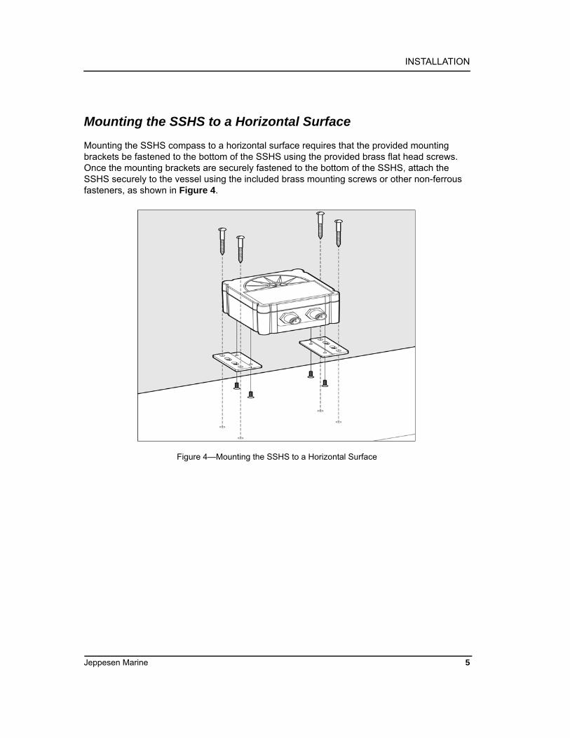
Mounting the SSHS compass to a horizontal surface requires that the provided mounting brackets be fastened to the bottom of the SSHS using the provided brass flat head screws. Once the mounting brackets are securely fastened to the bottom of the SSHS, attach the SSHS securely to the vessel using the included brass mounting screws or other non-ferrous fasteners, as shown in Figure 4.
Figure 4—Mounting the SSHS to a Horizontal Surface
Jeppesen Marine 5

Solid State Heading Sensor (SSHS) Owner’s Manual
Connecting the SSHS
You have a choice of connecting the SSHS to an NMEA 0183 interface, NMEA 2000 interface, or connecting to both interfaces simultaneously.
Attention: At the time of this printing, Jeppesen Marine does not support connection to an NMEA 2000 interface. While this manual describes how to make this connection, you will not be able to receive technical support for this interface.
Figure 5—NMEA 2000/NMEA 0183 Interface Connector Locations
Connecting to an NMEA 0183 Interface
The SSHS connects to an NMEA 0183 interface through an eight pin male connector using the 10-meter NMEA 0183 Cable that came in your product box. Connect the female end of the NMEA 0183 cable to the male connector on the SSHS (note the key on the connectors in Figure 6).
Figure 6—NMEA 0183 Connector Face Views
Ensure that the cable is connected securely and that the collar on the cable connector is firmly tightened. Connect the other end of the cable, which consists of individual wires using recommended practices for installing NMEA 0183 products.
6
INSTALLATION
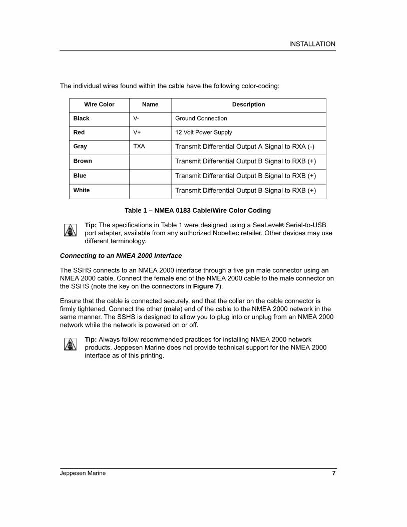
The individual wires found within the cable have the following color-coding:
Table 1 – NMEA 0183 Cable/Wire Color Coding
Tip: The specifications in Table 1 were designed using a SeaLevel® Serial-to-USB port adapter, available from any authorized Nobeltec retailer. Other devices may use different terminology.
Connecting to an NMEA 2000 Interface
The SSHS connects to an NMEA 2000 interface through a five pin male connector using an NMEA 2000 cable. Connect the female end of the NMEA 2000 cable to the male connector on the SSHS (note the key on the connectors in Figure 7).
Ensure that the cable is connected securely, and that the collar on the cable connector is firmly tightened. Connect the other (male) end of the cable to the NMEA 2000 network in the same manner. The SSHS is designed to allow you to plug into or unplug from an NMEA 2000 network while the network is powered on or off.
Tip: Always follow recommended practices for installing NMEA 2000 network products. Jeppesen Marine does not provide technical support for the NMEA 2000 interface as of this printing.
Wire Color Name Description
Black V- Ground Connection
Red V+ 12 Volt Power Supply
Gray TXA Transmit Differential Output A Signal to RXA (-)
Brown Transmit Differential Output B Signal to RXB (+)
Blue Transmit Differential Output B Signal to RXB (+)
White Transmit Differential Output B Signal to RXB (+)
Jeppesen Marine 7

Solid State Heading Sensor (SSHS) Owner’s Manual
Figure 7—NMEA 2000 Connector Face Views
Connecting Both NMEA 2000 and NMEA 0183 Interfaces
Attention: Connecting power through both the NMEA 2000 interface and NMEA 0183 interface is PROHIBITED and will nullify the warranty. Connecting the power through both connectors could potentially create a ground loop, which would render
one or both networks inoperative.
Note: Jeppesen Marine does not provide technical support for the NMEA 2000 interface as of this printing.
The SSHS can be simultaneously connected to both an NMEA 2000 network and an NMEA 0183 network providing that power is supplied only through the NMEA 2000 connector and not through the NMEA 0183 connector.
Follow the steps for connecting to an NMEA 2000 network and an NMEA 0183 network as listed on the previous pages, making sure to supply power ONLY through the NMEA 2000 network.
Checking Connections
Once the NMEA 2000 and / or NMEA 0183 connections to the Nobeltec SSHS have been completed, verify that the heading information is being properly transmitted by observing an appropriate display. (See Page 19 – Troubleshooting).
8

CALIBRATION
CALIBRATION
Warning: It is imperative that calibration procedures be carried out upon installation of the SSHS to ensure accurate readings.
In order to provide accurate heading indication, the SSHS must be calibrated after installation. The two calibration procedures are Magnetic Deviation Calibration (see below) and Installation-Offset Correction (see Page 13).
Calibration should be carried out immediately after initial compass installation, and again any time that the magnetic environment of the vessel has changed significantly (for example, if new cables have been routed near the compass or new equipment made of ferrous metal has been installed near the compass).
Methods of Calibrating for Magnetic Deviation
Magnetic and / or ferrous items near your SSHS magnetic compass can cause errors in the compass’ heading output. These errors are referred to as magnetic deviation.
The SSHS compass can compensate for heading errors caused by magnetic deviation by learning about the magnetic environment in which it has been mounted.
Magnetic Deviation Calibration is done using one of three possible procedures:
• Method 1. Automatically at Power-Up (see Page 14)• Method 2. Through the NMEA 0183 Interface (see Appendix A)• Method 3. Through the NMEA 2000 Interface (see Appendix B)*
Method #1 is automatic when power is removed and re-supplied during compass use. Methods 2 & 3 allow users with direct access to NMEA 0183 and / or NMEA 2000 interfaces to perform magnetic deviation calibration directly through those interfaces (see Appendices A and B). These direct-access methods provide an indication of success or failure and the causes of failure, when applicable.
Note: Jeppesen Marine does not provide technical support for the NMEA 2000 interface as of this printing.
Each of these three methods require that the vessel be turned in successive circles, during which time the SSHS uses the changing heading information and readings from the angular rate sensor to calculate hard and soft iron magnetic deviation(s).
Upon a successful completion of deviation calibration, the SSHS stores the deviation values in permanent memory for subsequent compensation. Under certain conditions (i.e., turning too quickly or too slowly), the SSHS may not successfully complete the calibration process, and will be unable to store the deviation values. Therefore, it is important to always verify that the deviation calibration process completed successfully.
Jeppesen Marine 9

Solid State Heading Sensor (SSHS) Owner’s Manual
Automatic Power-Up Deviation Calibration
Automatic Power-Up Deviation Calibration is accomplished by turning the vessel through four complete circles within 10 minutes of re-supplying power to the compass (see Step 5).
Tip: This method should be used in calm, flat waters where there is no set or drift associated with current or wind.
The procedure is as follows:
1. Ensure that the compass has been properly installed (see Page 6).
2. Turn on power to the sensor and wait one minute while it initializes and sets.
3. Turn the vessel in either direction until you complete a full 360° turn in 1½-2½ minutes or fewer (try to keep your turn over 1½ minutes for a complete circle).
4. While continuing to turn the vessel as indicated in Step 3, remove the power to the compass, and re-supply power. This initiates deviation calibration.
5. Continue turning the vessel through four complete circles in fewer than 10 minutes from the time power was re-applied.
6. Verify that the SSHS successfully completed deviation calibration by comparing the compass’s readings to three or more known headings. One way to verify that the SSHS successfully completed a deviation calibration is to observe three or more Course Over Ground (COG) readings directly from your GPS device or through your Nobeltec Navigation Software, and compare them to the corresponding SSHS heading readings.
If the SSHS readings agree with the COG readings (or are off by a consistent amount), then the SSHS was in all likelihood successfully calibrated. This method assumes that the vessel’s actual heading closely resembles the COG.
Tip: While turning the vessel, try to maintain a circle by holding the rudder at a constant angle, minimizing the vessel’s pitch and roll by calibrating on calm, flat water.
Installation-Offset Correction
After installation and successful Magnetic Deviation Calibration, it is important to perform Installation-Offset Correction using your NMEA 0183 or 2000 interface to verify that the displayed compass heading, pitch, and roll match actual vessel heading, pitch, and roll.
Users with direct access to NMEA 0183 (see Appendix A) and / or NMEA 2000 (see Appendix B) interfaces can perform Installation-Offset Correction directly through those interfaces. These direct-access methods provide an indication of success or failure and the causes of failure, when applicable.
Note: Jeppesen Marine does not provide technical support for the NMEA 2000 interface as of this printing.
10

CALIBRATION
VARIATION
Variation is the angular difference between the True Meridian (great circle connecting the geographic poles) and the Magnetic Meridian (direction of the lines of magnetic flux). Variation has different values at different locations on the earth, with most areas undergoing change to the variation over time.
Normally, heading information is displayed as either a “true” heading (a direction relative to the geographic poles) or it is displayed as a “magnetic” heading (a direction relative to the lines of magnetic flux). North-seeking gyrocompasses are capable of measuring direction relative to the geographic poles (“true”) whereas magnetic compasses measure direction relative to the earth’s local magnetic flux (“magnetic”).
The SSHS is a magnetic compass; therefore, it requires an external source for variation if you wish to view your heading in “true” format.
The SSHS is capable of receiving variation in one of three ways:
1. Via the NMEA 0183 interface
2. Via the NMEA 2000 interface
3. Through manual variation entry
Normally, the SSHS will automatically use variation from either the NMEA 0183 or NMEA 2000 interface. However, you can force the SSHS to use variation from only the NMEA 0183, only the NMEA 2000 interface, or only use manually entered variation.
Warning: Multiple variation sources that are received by the SSHS (i.e., NMEA 0183 and NMEA 2000 interfaces) will cause confusion as to the correct source to be used for true heading indications. If more than one variation source is available, the SSHS
needs to be programmed to use the appropriate source for reporting subsequent true heading information. See Page 16 for details on choosing a specific variation source when more than one variation source is available.
Note: Jeppesen Marine does not provide technical support for the NMEA 2000 interface as of this printing.
Variation Input via NMEA 0183 Interface
As shipped from the factory, the SSHS automatically looks for variation data coming from the NMEA 0183 interface. The SSHS accepts variation data from the Recommended Minimum Specific GNSS Data (RMC) sentence, or the SSHS computes variation from the Course Over Ground and Ground Speed (VTG) sentence.
Jeppesen Marine 11

Solid State Heading Sensor (SSHS) Owner’s Manual
If the SSHS receives variation information from the NMEA 0183 interface, it will do the following (see Appendix A for enabling or disabling NMEA 0183 sentences):
1. Transmit the Heading, Deviation & Variation (HDG) sentence, including the variation field as seen from the RMC or VTG sentence over the NMEA 0183 interface if HDG is enabled.
2. Transmit the Heading True (HDT) sentence using variation data from the RMC or VTG sentence over the NMEA 0183 interface if HDT is enabled.
3. Transmit over the NMEA 2000 interface the Magnetic Variation PGN (127258) with the Variation Source field value corresponding to the received NMEA 0183 variation data from the RMC or VTG sentence. The PGN’s Variation Source field will be transmitted with the lowest possible quality indicator, which is “Manual Entry”.
Variation Input via the NMEA 2000 Interface
Note: Jeppesen Marine does not provide technical support for the NMEA 2000 interface as of this printing.
As shipped from the factory, the SSHS also automatically looks for variation data coming from the NMEA 2000 interface. The SSHS accepts variation data from the Magnetic Variation PGN (127258).
If the SSHS receives variation information from the NMEA 2000 interface, it will do the following:
1. Transmit the Heading, Deviation & Variation (HDG) sentence, including the variation field as seen from the Magnetic Variation PGN (127258) from the NMEA 2000 interface if HDG is enabled (see Appendix A for enabling or disabling NMEA 0183 sentences).
2. Transmit the Heading True (HDT) sentence using variation data from the Magnetic Variation PGN (127258) from the NMEA 2000 interface if HDG is enabled (see Appendix A for enabling or disabling NMEA 0183 sentences).
Variation Input via Manual Entry
If no other source of variation is available (i.e., neither the NMEA 0183 nor NMEA 2000 interface), the SSHS can be programmed with a fixed variation value for a given location (this value can be found on most navigational charts).
If variation is manually entered into the SSHS, it will then do the following:
1. Transmit the Heading, Deviation & Variation (HDG) sentence including the variation field as manually entered over the NMEA 0183 interface if HDG is enabled (see Appendix A for enabling or disabling NMEA 0183 sentences).
12
CALIBRATION
2. Transmit the Heading True (HDT) sentence using variation data as manually entered over the NMEA 0183 interface if HDT is enabled (see Appendix A for enabling or disabling NMEA 0183 sentences).
3. Transmit over the NMEA 2000 interface the Magnetic Variation PGN (127258) with the Variation Source field value corresponding to the manually entered variation. The PGN’s Variation Source field will be transmitted with the lowest possible quality indicator, which is “Manual Entry”.
Warning: Magnetic variation changes as your position on the earth changes; therefore, the variation should be adjusted with changes in position. The SSHS will not automatically adjust variation with changes in position; it is the responsibility of the
user to adjust variation with changes in position.
Variation Source Selection
As shipped from the factory, the SSHS automatically looks for variation from both the NMEA 0183 and NMEA 2000 interfaces. If there is only a single source of variation available (either the NMEA 0183 or the NMEA 2000 interface), then there is no need to manually select a variation source. However, if there are multiple variation sources (i.e., from both the NMEA 0183 and NMEA 2000 interfaces), or there is no source for variation, then it is necessary to select a specific variation source.
The SSHS can be programmed to use one of three possible variation sources:
• Variation from only the NMEA 0183 Interface• Variation from only the NMEA 2000 Interface• Variation from only Manual Entry
You can program the SSHS to accept a specific source for the variation data through the NMEA 0183 Interface. See Appendix A for details on programming the SSHS to use a specific variation source.
Jeppesen Marine 13

Solid State Heading Sensor (SSHS) Owner’s Manual
RATE OF TURN
Rate of Turn Damping Period Selection by NMEA 0183 Interface
The SSHS is capable of measuring a vessel’s rate of turn and outputting the information over both the NMEA 0183 and NMEA 2000 interfaces. Furthermore, the SSHS has a programmable damping period where the filter time can be increased for very slow turning vessels such as tugs pushing barges. Also, the SSHS rate of turn indication may be zeroed to correct for any temperature-induced offset.
The SSHS can be programmed with different damping periods and have the rate of turn indication zeroed using the NMEA 0183 Interface. See Appendix A for details on programming the SSHS to use a specific damping period.
Rate of Turn Zeroing
The SSHS may be used as a rate of turn indicator, which should read zero when the vessel is not turning. It is possible that the rate of turn indication has an offset; that is, it may show a non-zero value when the vessel is at rest. This offset changes with temperature but the SSHS has the ability to remember the offset at different temperatures.
14

PERIODIC MAINTENANCE
PERIODIC MAINTENANCE
Regular maintenance is important to ensure continued proper operation of the Nobeltec SSHS. Perform the following tasks periodically:
• Clean the unit with a soft cloth.• Do not use chemical cleaners on the Solid State Heading Sensor, as such cleaners
may remove markings or corrode the compass enclosure or seals.• Ensure the unit is mounted securely and cannot be moved relative to the mounting
surface. Periodically check and tighten the mounting screws (if loose), and repeat the magnetic deviation calibration and installation-offset correction.
• Check the security of the cables connected to the NMEA 0183 and / or NMEA 2000 interfaces and tighten if necessary.
Jeppesen Marine 15

Solid State Heading Sensor (SSHS) Owner’s Manual
TROUBLESHOOTING
If you notice unexpected operation of the SSHS, follow the troubleshooting procedures in this section to remedy simple problems.
If these steps do not solve your problem, please contact Technical Support (see the Back Cover of this manual for contact information).
Warning: There are no user-serviceable components inside the SSHS. Opening the SSHS will expose the sensitive electronic components to movement and adverse environmental conditions that may render the compass inoperative. Please do not
open the SSHS, as this will automatically void the warranty. If service is required, please return the unit to an authorized Jeppesen Marine service location (see Page 38).
Symptom Troubleshooting Procedure
No heading output • Check the connections to the NMEA 0183 connector and / or NMEA 2000 connector and tighten if necessary.
• Ensure that power is supplied to the connected NMEA 2000 or NMEA 0183 cable
Inaccurate heading output • Ensure the SSHS is still mounted securely.• Ensure the SSHS is still in a clean magnetic environment and that no power or ignition cables or magnetic or ferrous objects have been moved near the SSHS• Repeat the magnetic deviation compensation and installation-offset correction procedures
16

TECHNICAL SPECIFICATIONS
TECHNICAL SPECIFICATIONS
Specifications
Certifications
NMEA 2000 Parameter Group Numbers (PGNs)
See Appendix B for Details
Parameter Parameter Comment
Static Heading Accuracy <1° rms ±45° Pitch and Roll - 15°C to 35°C
Heading Display Resolution
0.1°
Settling Time 1 Second To Static Accuracy after 35°/Second Turn
Heading Deviation Yes Automatic or Initiated through Interfaces
Alignment Calibration Yes Manual or Initiated through Interfaces
Pitch and Roll Range <1* ±45° Pitch and Roll - 15°C to 35°C
Rate of Turn Range 0° - 90° per Second
Rate of Turn Accuracy ±1° per Second 0° Pitch and Roll - 15°C to 35°C
Parameter Parameter
NMEA 2000 Level A
Maritime Navigation and Radio-Communication Equipment & Systems
Tested to IEC 60945
FCC and CE Mark Electromagnetic Compatibility
Description PGN# PGN Name Default Rate
Periodic Data PGNs 127250 Vessel Heading 10 Times/Second
127257 Attitude 1 Time/Second
127251 Rate of Turn 10 Times/Second
Response to Requested 126464 PGN List (Transmit and Receive) N/A
PGNs 126996 Product Information N/A
126998 Configuration Information N/A
Jeppesen Marine 17
Solid State Heading Sensor (SSHS) Owner’s Manual
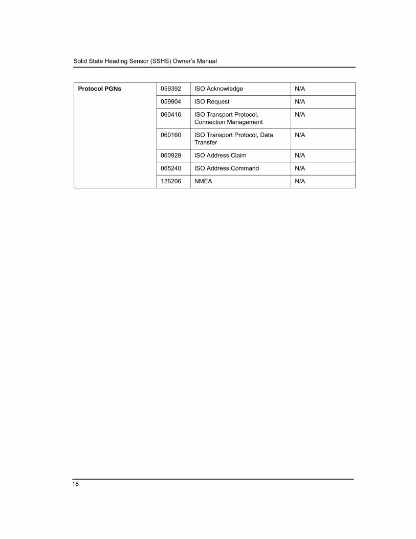
Protocol PGNs 059392 ISO Acknowledge N/A
059904 ISO Request N/A
060416 ISO Transport Protocol, Connection Management
N/A
060160 ISO Transport Protocol, Data Transfer
N/A
060928 ISO Address Claim N/A
065240 ISO Address Command N/A
126206 NMEA N/A
18

TECHNICAL SPECIFICATIONS
NMEA 0183 Sentences - See Appendix A for Details
Description Acronym Sentence Name Default Rate
TransmittedSentences
HDG Heading, Deviation, and Variation 10 Times/Second
HDM Heading, Magnetic (Not normally transmitted, see Appendix A)
N/A
HDT Heading True (Not normally transmitted, see Appendix A)
N/A
ROT Rate of Turn 5 Times/Second
PMAROUT Manufacturer’s proprietary Attitude (Pitch and Roll)
1 Time/Second
TXT Text Transmission N/A
Received Sentences
RMC Recommended Minimum Specific GNSS Data N/A
VTG Course Over Ground and Ground Speed N/A
Jeppesen Marine 19
Solid State Heading Sensor (SSHS) Owner’s Manual
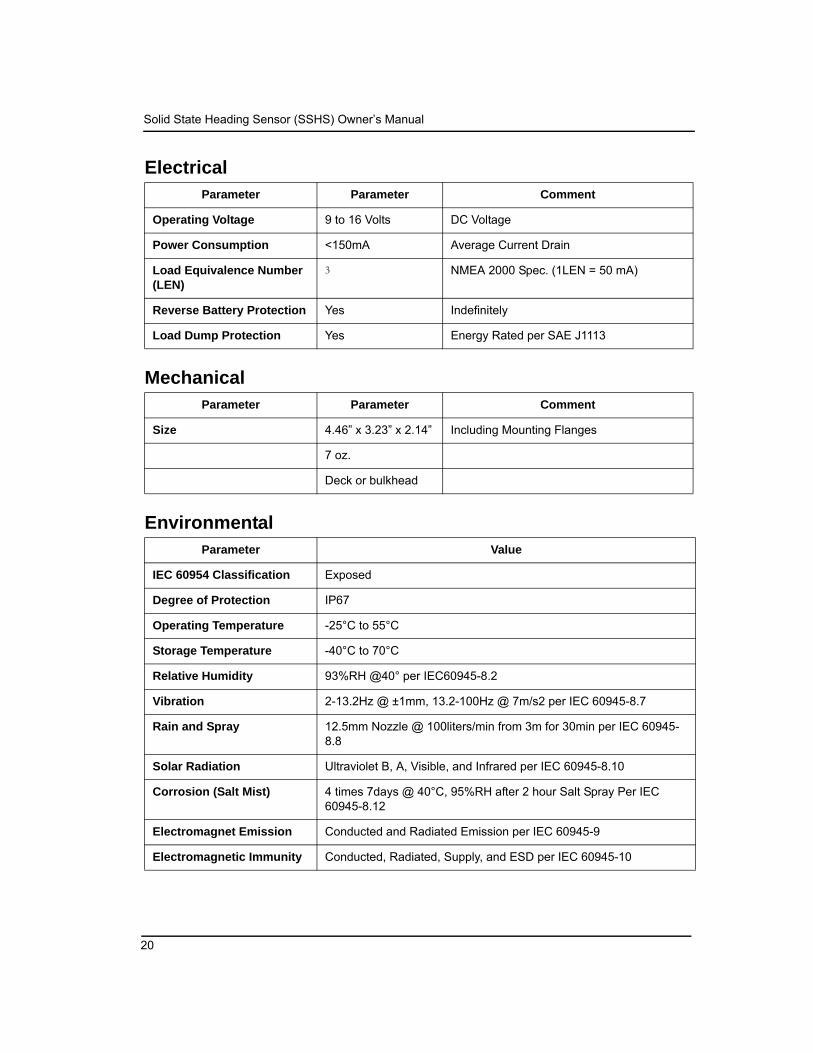
Electrical
Mechanical
Environmental
Parameter Parameter Comment
Operating Voltage 9 to 16 Volts DC Voltage
Power Consumption <150mA Average Current Drain
Load Equivalence Number (LEN)
3 NMEA 2000 Spec. (1LEN = 50 mA)
Reverse Battery Protection Yes Indefinitely
Load Dump Protection Yes Energy Rated per SAE J1113
Parameter Parameter Comment
Size 4.46” x 3.23” x 2.14” Including Mounting Flanges
7 oz.
Deck or bulkhead
Parameter Value
IEC 60954 Classification Exposed
Degree of Protection IP67
Operating Temperature -25°C to 55°C
Storage Temperature -40°C to 70°C
Relative Humidity 93%RH @40° per IEC60945-8.2
Vibration 2-13.2Hz @ ±1mm, 13.2-100Hz @ 7m/s2 per IEC 60945-8.7
Rain and Spray 12.5mm Nozzle @ 100liters/min from 3m for 30min per IEC 60945-8.8
Solar Radiation Ultraviolet B, A, Visible, and Infrared per IEC 60945-8.10
Corrosion (Salt Mist) 4 times 7days @ 40°C, 95%RH after 2 hour Salt Spray Per IEC 60945-8.12
Electromagnet Emission Conducted and Radiated Emission per IEC 60945-9
Electromagnetic Immunity Conducted, Radiated, Supply, and ESD per IEC 60945-10
20

TECHNICAL SPECIFICATIONS
Safety Precautions Dangerous Voltage, Electromagnetic Radio Frequency per IEC 60945-12
Jeppesen Marine 21

Solid State Heading Sensor (SSHS) Owner’s Manual
22
APPENDIX A – NMEA 0183 INTERFACING
APPENDIX A – NMEA 0183 INTERFACING
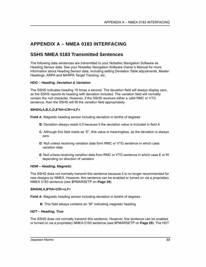
SSHS NMEA 0183 Transmitted Sentences
The following data sentences are transmitted to your Nobeltec Navigation Software as Heading Sensor data. See your Nobeltec Navigation Software Owner’s Manual for more information about Heading Sensor data, including setting Deviation Table adjustments, Master Headings, ARPA and MARPA Target Tracking, etc.
HDG – Heading, Deviation & Variation
The SSHS indicates heading 10 times a second. The deviation field will always display zero, as the SSHS reports its heading with deviation included. The variation field will normally contain the null character. However, if the SSHS receives either a valid RMC or VTG sentence, then the SSHS will fill the variation field appropriately.
$IIHDG,A,B,C,D,E*hh<CR><LF>
Field A: Magnetic heading sensor including deviation in tenths of degrees
B: Deviation always reads 0.0 because it the deviation value is included in field A
C: Although this field reads as “E”, this value is meaningless, as the deviation is always zero
D: Null unless receiving variation data form RMC or VTG sentence in which case variation data
E: Null unless receiving variation data from RMC or VTG sentence in which case E or W depending on direction of variation
HDM – Heading, Magnetic
The SSHS does not normally transmit this sentence because it is no longer recommended for new designs by NMEA. However, this sentence can be enabled or turned on via a proprietary NMEA 0183 sentence (see $PMARSETP on Page 29).
$IIHDM,A,B*hh<CR><LF>
Field A: Magnetic heading sensor including deviation in tenths of degrees
B: This field always contains an “M” indicating magnetic heading
HDT – Heading, True
The SSHS does not normally transmit this sentence. However, this sentence can be enabled or turned on via a proprietary NMEA 0183 sentence (see $PMARSETP on Page 29). The HDT
Jeppesen Marine 23
Solid State Heading Sensor (SSHS) Owner’s Manual
sentence works in collaboration with the reception of an RMC or VTG sentence to produce true heading.
$IIHDT,A,B*hh<CR><LF>
Field A: Null unless receiving variation from RMC and VTG in which case magnetic heading including deviation and variation in tenths of degrees
B: This field always contains a “T” indicating true magnetic heading
ROT – Rate of Turn
The SSHS indicates the vessel’s rate of turn 5 times a second.
$IIROT,A,B*hh<CR><LF>
Field A: Rate of turn in degrees/minute where “-“ indicates the bow turning to port
B: This field indicates whether data is valid, an “A” indicates that the data is valid where a “V” indicates invalid data
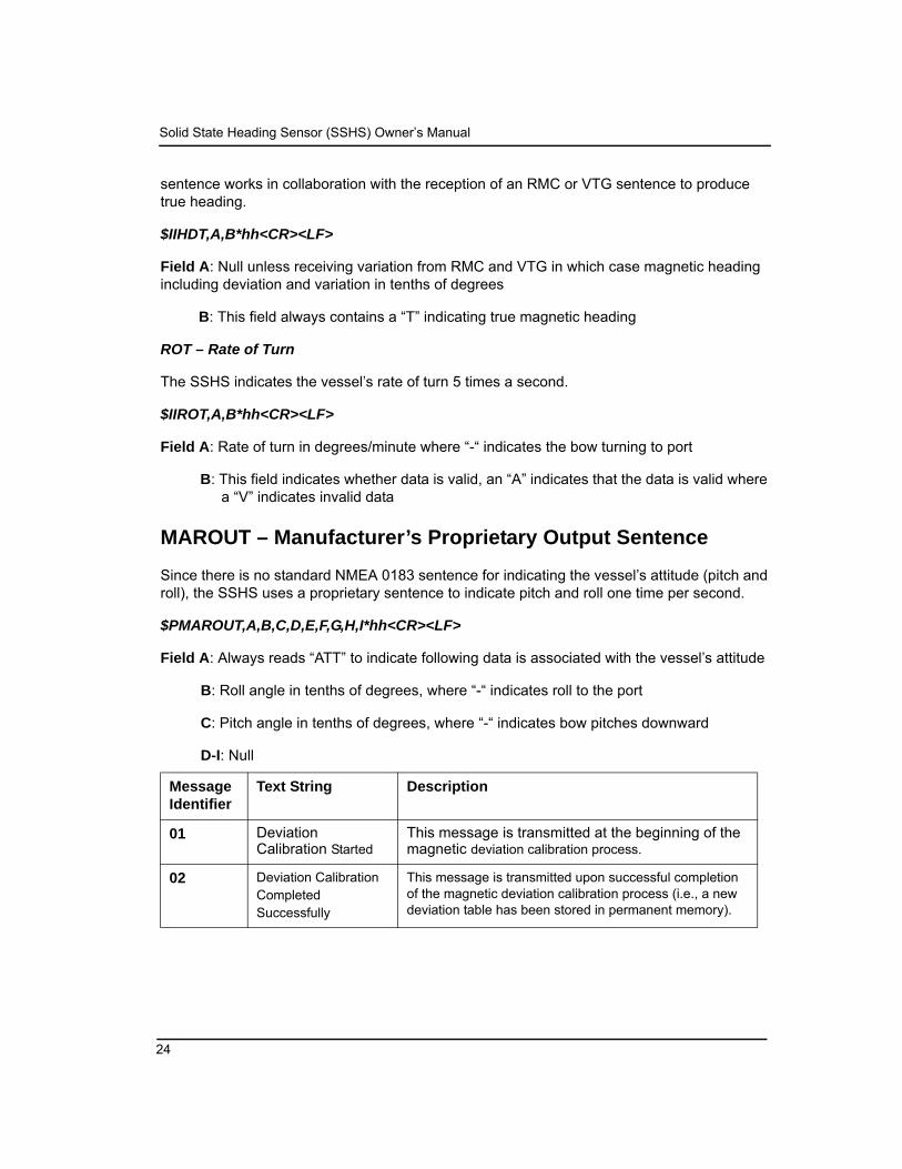
MAROUT – Manufacturer’s Proprietary Output Sentence
Since there is no standard NMEA 0183 sentence for indicating the vessel’s attitude (pitch and roll), the SSHS uses a proprietary sentence to indicate pitch and roll one time per second.
$PMAROUT,A,B,C,D,E,F,G,H,I*hh<CR><LF>
Field A: Always reads “ATT” to indicate following data is associated with the vessel’s attitude
B: Roll angle in tenths of degrees, where “-“ indicates roll to the port
C: Pitch angle in tenths of degrees, where “-“ indicates bow pitches downward
D-I: Null
Message Identifier
Text String Description
01 Deviation Calibration Started
This message is transmitted at the beginning of the magnetic deviation calibration process.
02 Deviation CalibrationCompletedSuccessfully
This message is transmitted upon successful completion of the magnetic deviation calibration process (i.e., a new deviation table has been stored in permanent memory).
24

APPENDIX A – NMEA 0183 INTERFACING
Table 3—TXT Status Message Guide
TXT – Text Transmission
The SSHS transmits various status messages using the text transmission sentence.
$IITXT,A,B,C,D*hh<CR><LF>
Field A: Always reads “01”
03 Deviation CalibrationFailed to Complete
The SSHS attempts to perform calibration five times before giving up and issuing this sentence. Each time the SSHS encounters an error (see message identifiers 04, 05, and 06) it restarts the Appendix A – NMEA 0183 Interfacing27 calibration process. Upon the 5th error, the SSHS exits the calibration routine and it must be restarted before it will once again try to perform deviation calibration.
04 Deviation CalibrationTurning Too Fast
During calibration, the vessel must not turn too fast where the SSHS is unable to reliably develop deviation data. If the SSHS senses the vessel turning to quickly, it will issue this message and restart deviation calibration as long as it has not failed five times.
05 Deviation CalibrationTurning Too Slow
During calibration, the vessel must not turn too slowly where the SSHS is unable to reliably develop deviation data. If the SSHS senses the vessel turning to slowly, it will issue this message and restart deviation calibration as long as it has not failed five times.
06 Deviation CalibrationInvalid Movement
During calibration, the vessel must not jerk or reverse directions where the SSHS is unable to reliably develop deviation data. If the SSHS senses an invalid movement, it will issue this message and restart deviation calibration as long as it has not failed five times.
95 Serial Number:xxxxxxx
The SSHS transmits this sentence once after it is powered up to indicate its serial number.
96 Baud Rate: 4800 The SSHS transmits this sentence once after it is powered up to indicate its baud rate.
97 SW Version: 1.2 The SSHS transmits this sentence once after it is powered up to indicate its software version.
98 Model Version: 1.0 The SSHS transmits this sentence once after it is powered up to indicate its model version.
99 Model ID: SSHS The SSHS transmits this sentence once after it is powered up to indicate its model identification.
Jeppesen Marine 25

Solid State Heading Sensor (SSHS) Owner’s Manual
B: Always reads “01”
C: Message identifier (see Table 3)
D: Text string (see Table 3)
SSHS NMEA 0183 Received Sentences
Note on NMEA 0183 Checksums
For ease of manual configuration of the SSHS via the NMEA 0183 Interface, NMEA 0183 checksums are optional. If no checksum is present in a received sentence, then the sentence is treated as if a valid checksum were present. If a checksum is present in a received sentence, then it is used to check the integrity of the sentence, which is accepted only if the calculated checksum agrees with the checksum at the end of the received sentence.
To ensure the best possible data integrity, Jeppesen Marine recommends using NMEA 0183 checksums whenever possible.
RMC – Recommended Minimum Specific GNSS Data
The SSHS is capable of receiving the RMC sentence and extracting the magnetic variation data for subsequent insertion into the appropriate fields for transmission of the HDG and HDT sentences.
The SSHS uses an aging technique (referred to as “Variation Lifetime”) where variation data is output in the HDG and HDT sentences for a period of 5 seconds after the RMC sentence is received. The Variation Lifetime can be re-programmed to a shorter or longer period (see PMARSETP on Page 29).
VTG – Course Over Ground and Ground Speed
The SSHS is capable of receiving the VTG sentence and computing the magnetic variation data for subsequent insertion into the appropriate fields for transmission of the HDG and HDT sentences. The variation is computed by observing the difference between the true course over ground and the magnetic course over ground.
The SSHS uses an aging technique (referred to as “Variation Lifetime”) where variation data is output in the HDG and HDT sentences for a period of 5 seconds after the VTG sentence is received. The Variation Lifetime can be re-programmed to a shorter or longer time period (see PMARSETP on Page 29).
PMAREXE – Manufacturer’s proprietary Execute Sentence
The SSHS can be commanded via this proprietary sentence to execute one of several commands.
26

APPENDIX A – NMEA 0183 INTERFACING
$PMAREXE,SSHS,,F0,,,,<CR><LF>
This command causes the SSHS to be reset and is useful for initiating deviation calibration.
$PMAREXE,SSHS,,FD,0,,,<CR><LF>
This command causes the SSHS to stop outputting normal periodic data (like heading) and is useful for observing non-periodic sentences such as status sentences during deviation calibration.
$PMAREXE,SSHS,,FD,1,,,<CR><LF>
This command causes the SSHS to once again output periodic data. Normally, periodic data is disabled during the calibration process such that status messages are easy to see and not lost within normal periodic data. This sentence is used to turn the periodic data back on.
$PMAREXE,SSHS,,24,”known heading in tenths of degrees”,,,<CR><LF>
This is the command used to perform installation-offset where the compass is aligned to a known heading and the pitch and roll are zeroed to the vessel’s current attitude. If the current or known heading is 177.0°, then a value of 1770 should be programmed.
$PMAREXE,SSHS,,5D,0,”variation”,,<CR><LF>
This command causes the SSHS to use a manual entry for variation (variation is programmed using 1/10 of a degree resolution – as an example use 2.3 in the “variation” field for a 2.3° variation.
$PMAREXE,SSHS,,5D,1,,,<CR><LF>
This command causes the SSHS to use variation data from the NMEA 2000 interface and ignore all other variation sources (i.e., NMEA 0183 interface and manual entries).
$PMAREXE,SSHS,,5D,2,,,<CR><LF>
This command causes the SSHS to use variation data from the NMEA 0183 interface and ignore all other variation sources (i.e., NMEA 2000 interface and manual entries).
$PMAREXE,SSHS,,5D,3,,,<CR><LF>
This command causes the SSHS to use resort back to the factory default where variation data is used from either the NMEA 0183 interface or the NMEA 2000 interface.
$PMAREXE,SSHS,,5E,2,”damping period”,,<CR><LF>
This command causes the SSHS to use a rate of turn damping rate corresponding to the value programmed in “damping period”. The damping period is programmable from 100 to 60000, which represents 100ms to 60 seconds.
Jeppesen Marine 27
Solid State Heading Sensor (SSHS) Owner’s Manual
$PMAREXE,SSHS,,5E.11,,,<CR><LF>
This command causes the SSHS to zero the rate of turn indication and record the compensation value used, along with the current operating temperature of the compass. The boat must remain at rest for a period of one minute after this command is issued.
$PMAREXE,SSHS,,5E.12,,,<CR><LF>
This command causes the SSHS to cancel any rate of turn zeroing operations currently in progress.
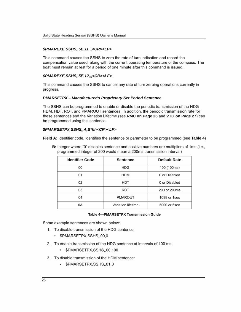
PMARSETPX – Manufacturer’s Proprietary Set Period Sentence
The SSHS can be programmed to enable or disable the periodic transmission of the HDG, HDM, HDT, ROT, and PMAROUT sentences. In addition, the periodic transmission rate for these sentences and the Variation Lifetime (see RMC on Page 26 and VTG on Page 27) can be programmed using this sentence.
$PMARSETPX,SSHS,,A,B*hh<CR><LF>
Field A: Identifier code, identifies the sentence or parameter to be programmed (see Table 4)
B: Integer where “0” disables sentence and positive numbers are multipliers of 1ms (i.e., programmed integer of 200 would mean a 200ms transmission interval)
Table 4—PMARSETPX Transmission Guide
Some example sentences are shown below:
1. To disable transmission of the HDG sentence:• $PMARSETPX,SSHS,,00,0
2. To enable transmission of the HDG sentence at intervals of 100 ms:• $PMARSETPX,SSHS,,00,100
3. To disable transmission of the HDM sentence:• $PMARSETPX,SSHS,,01,0
Identifier Code Sentence Default Rate
00 HDG 100 (100ms)
01 HDM 0 or Disabled
02 HDT 0 or Disabled
03 ROT 200 or 200ms
04 PMAROUT 1099 or 1sec
0A Variation lifetime 5000 or 5sec
28
APPENDIX A – NMEA 0183 INTERFACING
4. To enable transmission of the HDM sentence at intervals of 1000 ms:• $PMARSETPX,SSHS,,01,1000
5. To disable transmission of the HDT sentence:• $PMARSETPX,SSHS,,02,0
6. To enable transmission of the HDT sentence at intervals of 100 ms:• $PMARSETPX,SSHS,,02,100
7. To disable transmission of the ROT sentence:• $PMARSETPX,SSHS,,03,0
8. To enable transmission of the ROT sentence at intervals of 100 ms:• $PMARSETPX,SSHS,,03,100
9. To disable transmission of the PMAROUT sentence:• $PMARSETPX,SSHS,,04,0
10. To enable transmission of the PMAROUT sentence at intervals of 1 sec:• $PMARSETPX,SSHS,,04,1000
SSHS NMEA 0183 Initiated Deviation Calibration
NMEA 0183 initiated deviation calibration is accomplished by turning the vessel through at least 3 complete circles after the SSHS receives a manufacturer’s proprietary NMEA 0183 sentence.
The procedure is as follows:
1. Ensure that the compass has been properly installed per Installation on Page 6.
2. Warm up the compass by operating it approximately 10 minutes.
3. Turn the vessel (either direction) such that you complete a full 360° turn in 2½ minutes or less (try not to go below 1 minute for a complete circle),
4. Send the following manufacturer’s proprietary NMEA0183 sentence to the SSHS while continuing to turn the vessel:
• $PMAREXE,SSHS,,FD,0,,,<CR><LF> This will turn off all periodic transmissions such that you can easily see status messages associated with the calibration process
• $PMAREXE,SSHS,,F0,,,,<CR><LF> This will initiate a reset and force the SSHS to start the calibration process.
Jeppesen Marine 29
Solid State Heading Sensor (SSHS) Owner’s Manual
5. Continue turning the vessel through at least 3 circles until you see one of the following manufacturer’s proprietary sentences:
• $IITXT,01,01,02,Deviation Calibration Successfully Completed*17<CR><LF> This sentence indicates a successful calibration and you can jump to step number 6.
• $IITXT,01,01,03,Deviation Calibration Failed To Complete*43<CR><LF> This sentence indicates that the calibration failed (return to step number 1).
6. Turn the periodic transmissions back on by sending the following manufacturer’s proprietary NMEA0183 sentence to the SSHS - $PMAREXE,SSHS,,FD,1,,,<CR><LF>
7. Proceed to Installation-Offset Correction.
SSHS NMEA 0183 Installation-Offset Correction
Installation-offset correction can be performed by sending a manufacturer’s proprietary NMEA 0183 sentence to the SSHS. The procedure is as follows:
1. Make sure the vessel is laying in flat water on a known heading.
2. Send the following manufacturer’s proprietary NMEA 0183 sentence to the SSHS:
$PMAREXE,SSHS,,24,”known heading in tenths of degrees”,,,<CR><LF>
Where “known heading in tenths of degrees” is expressed in 10th of degrees (i.e., 121.7° would be programmed as 1217)
Sending this manufacturer’s proprietary NMEA 0183 sentence to the SSHS causes the heading, roll, and pitch offsets to be written to permanent memory.
30

APPENDIX B – NMEA 2000 INTERFACING
APPENDIX B – NMEA 2000 INTERFACING
Note: Jeppesen Marine does not provide technical support for the NMEA 2000 interface as of this printing.
SSHS NMEA 2000 Periodic Data Transmitted PGNs
PGN 127250 – Vessel Heading
The SSHS uses this PGN to indicate the vessel’s heading. The Heading Sensor Reading (Field 2) includes deviation, therefore Deviation (Field 2) always contains zero. Variation (Field 4) is not provided by the SSHS, therefore, this field always contains a value of 0x7FFF (data not available). Since the SSHS’s core technology is based on magnetometers, the Heading Sensor Reference (field 5) is always set to magnetic.
Field 1: SID – The sequence identifier field is used to tie related PGNs together. For example, the SSHS will transmit identical SIDs for Vessel Heading (PGN 127250), Attitude (127257), and Rate of Turn (127251) to indicate that the readings are linked together (i.e., the data from each PGN was taken at the same time although they are reported at slightly different times).
2: Heading Sensor Reading – This field is used to report the vessel’s heading and includes deviation assuming a deviation table has been successfully loaded through the magnetic deviation calibration process.
3: Deviation – The deviation is included in field 2, therefore this field always reads as 0.
4: Variation – The SSHS does not use this field so the field is transmitted with the value 0x7FFF (data not available). See PGN 127258 for information regarding the SSHS and its ability to transmit magnetic variation.
5: Heading Sensor Reference – The SSHS transmits a “1” in this field to indicate that the heading is referenced to magnetic North.
6: Reserved – This field is reserved by NMEA; therefore, the SSHS sets all bits to a logic 1.
PGN 127251 – Rate of Turn
The SSHS uses this PGN to indicate the vessel’s rate of turn.
Field 1: SID – The sequence identifier field is used to tie related PGNs together. For example, the SSHS will transmit identical SIDs for Vessel Heading (PGN 127250), Attitude (127257), and Rate of Turn (127251) to indicate that the readings are linked together (i.e., the data from each PGN was taken at the same time although they are reported at slightly different times).
Jeppesen Marine 31
Solid State Heading Sensor (SSHS) Owner’s Manual
2: Rate of Turn – This field is used to report the vessel’s rate of turn.
3: Reserved – This field is reserved by NMEA; therefore, the SSHS sets all bits to a logic 1.
PGN 127257 – Attitude
The SSHS uses this PGN to indicate the vessel’s attitude (pitch and roll). The Yaw (field 2) is not used, therefore, this field always contains 0x7FFF (data not available).
Field 1: SID – The sequence identifier field is used to tie related PGNs together. For example, the SSHS will transmit identical SIDs for Vessel Heading (PGN 127250), Attitude (127257), and Rate of Turn (127251) to indicate that the readings are linked together (i.e., the data from each PGN was taken at the same time although they are reported at slightly different times).
2: Yaw – This field always contains a value of 0x7FFF (data not available).
3: Pitch – This field is used to report the vessel’s pitch.
4: Roll – This field is used to report the vessel’s roll.
5: Reserved – This field is reserved by NMEA; therefore, the SSHS sets all bits to a logic 1.
PGN 127258 – Magnetic Variation
The SSHS may or may not periodically transmit this PGN depending on whether or not it has been programmed with the local magnetic variation. Programming the magnetic variation (through a Nobeltec display product like the DSM200) will cause the SSHS to transmit this PGN once per second. If the local magnetic variation is not known, then the variation can be disabled (again, through a display product like the DSM200) at which time the SSHS will cease to transmit this PGN.
Field 1: SID – The sequence identifier field is used to tie related PGNs together. For example, the SSHS will transmit identical SIDs for Vessel Heading (PGN 127250), Attitude (127257), and Rate of Turn (127251) to indicate that the readings are linked together (i.e., the data from each PGN was taken at the same time although they are reported at slightly different times).
2: Variation Source – This field always contains a value of 0x00 (manual entry).
3: Reserved – This field is reserved by NMEA; therefore, the SSHS sets all bits to a logic1.
4: Age of Service – This field always contains a value of 0x7FFF (data not available).
5: Variation – This field is used to report the local magnetic variation as entered by the user. Positive values are Easterly and negative values are Westerly.
32
APPENDIX B – NMEA 2000 INTERFACING
Warning: Magnetic variation changes as your location on the earth changes. It should be adjusted with these changes. The SSHS will not make these changes automatically.
SSHS NMEA 2000 Non-Periodic Data Transmitted PGNs
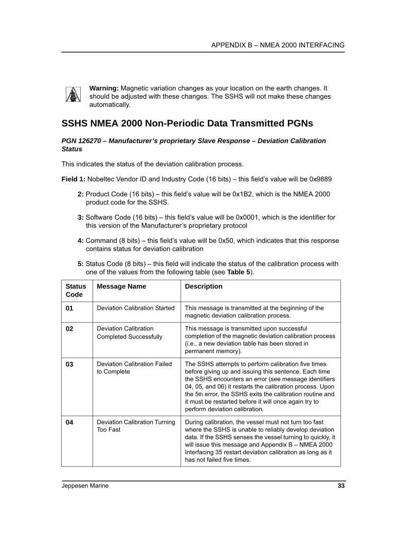
PGN 126270 – Manufacturer’s proprietary Slave Response – Deviation Calibration Status
This indicates the status of the deviation calibration process.
Field 1: Nobeltec Vendor ID and Industry Code (16 bits) – this field’s value will be 0x9889
2: Product Code (16 bits) – this field’s value will be 0x1B2, which is the NMEA 2000 product code for the SSHS.
3: Software Code (16 bits) – this field’s value will be 0x0001, which is the identifier for this version of the Manufacturer’s proprietary protocol
4: Command (8 bits) – this field’s value will be 0x50, which indicates that this response contains status for deviation calibration
5: Status Code (8 bits) – this field will indicate the status of the calibration process with one of the values from the following table (see Table 5).
Status Code
Message Name Description
01 Deviation Calibration Started This message is transmitted at the beginning of the magnetic deviation calibration process.
02 Deviation CalibrationCompleted Successfully
This message is transmitted upon successful completion of the magnetic deviation calibration process (i.e., a new deviation table has been stored in permanent memory).
03 Deviation Calibration Failed to Complete
The SSHS attempts to perform calibration five times before giving up and issuing this sentence. Each time the SSHS encounters an error (see message identifiers 04, 05, and 06) it restarts the calibration process. Upon the 5th error, the SSHS exits the calibration routine and it must be restarted before it will once again try to perform deviation calibration.
04 Deviation Calibration Turning Too Fast
During calibration, the vessel must not turn too fast where the SSHS is unable to reliably develop deviation data. If the SSHS senses the vessel turning to quickly, it will issue this message and Appendix B – NMEA 2000 Interfacing 35 restart deviation calibration as long as it has not failed five times.
Jeppesen Marine 33

Solid State Heading Sensor (SSHS) Owner’s Manual
Table 5—PGN 126270 Status Codes
SSHS NMEA 2000 Received PGNs
PGN 126208 – NMEA Command Group Function – Manufacturer’s Proprietary Reset
This will initiate a reset and force the SSHS to start the calibration process.
Field 1: Complex Command Group Function Code (8 bits) – set this field’s value to 0x01, which denotes a command PGN.
2: Commanded PGN (24 bits) – set this field’s value to 126720, which denotes the Manufacturer’s proprietary PGN.
3: Priority Setting (4 bits) – set this field’s value to 0x8, which indicates to leave priority settings unchanged.
4: Reserved (4 bits) – set this field’s value to 0xF, which is the value for a reserved field of this size.
5: Number of Pairs of Commanded Parameters to Follow (8 bits) – set this field’s value to 0x4, indicating that four parameters will follow.
6: Number of First Commanded Parameter (8 bits) – set this field’s value to 0x1
7: Nobeltec Vendor ID and Industry Code (16 bits) – set this field’s value to 0x9889
8: Number of Second Commanded Parameter (8 bits) – set this field’s value to 0x02
9: Product Code (16 bits) – set this field’s value to 0x1B2, which is the NMEA 2000 product code for the SSHS.
10: Number of Third Commanded Parameter (8 bits) – set this field’s value to 0x03
11: Software Code (16 bits) – set this field’s value to 0x0001, which is the identifier for this version of the Manufacturer’s proprietary protocol.
05 Deviation Calibration Turning Too Slow
During calibration, the vessel must not turn too slowly where the SSHS is unable to reliably develop deviation data. If the SSHS senses the vessel turning to slowly, it will issue this message and restart deviation calibration as long as it has not failed five times.
06 DeviationCalibration InvalidMovement
During calibration, the vessel must not jerk or reverse directions where the SSHS is unable to reliably develop deviation data. If the SSHS senses an invalid movement, it will issue this message and restart deviation calibration as long as it has not failed five times.
34

APPENDIX B – NMEA 2000 INTERFACING
12: Nobeltec Command – set this field’s value to 0xF0, which will initiate a reset and start the calibration process.
PGN 126208 – NMEA Command Group Function – Manufacturer’s Proprietary Installation Offset.
This PGN performs the installation offset of the compass. It sets the roll and pitch outputs to zero at the compass’ current orientation and sets the heading reading for the current orientation to the value given by the PGN.
Field 1: Complex Command Group Function Code (8 bits) – set this field’s value to 0x01, which denotes a command PGN.
2: Commanded PGN (24 bits) – set this field’s value to 126720 decimal (0x1EF00 hexadecimal), which denotes the Manufacturer’s proprietary PGN.
3: Priority Setting (4 bits) – set this field’s value to 0x8, which indicates to leave priority settings unchanged.
4: Reserved (4 bits) – set this field’s value to 0xF, which is the value for a reserved field of this size.
5: Number of Pairs of Commanded Parameters to Follow (8 bits) – set this field’s value to 0x4, indicating that four parameters will follow.
6: Number of First Commanded Parameter (8 bits) – set this field’s value to 0x1
7: Nobeltec Vendor ID and Industry Code (16 bits) – set this field to 0x9889, which is a combination of Nobeltec’s vendor ID and the marine industry code.
8: Number of Second Commanded Parameter (8 bits) – set this field’s value to 0x02
9: Product Code (16 bits) – set this field’s value to 0x1B2, which is the NMEA 2000 product code for the SSHS.
10: Number of Third Commanded Parameter (8 bits) – set this field’s value to 0x03
11: Software Code (16 bits) – set this field’s value to 0x0001, which is the identifier for this version of the Manufacturer’s proprietary protocol.
12: Nobeltec Command (8 bits) – set this field’s value to 0x24, which will cause installation-offset calibration to be performed.
13: Heading Value (16 bits) – set this field’s value to the current known heading in tenths of degrees (a value between 0 and 3599). For example, 121.7° would be programmed as 1217 decimal, or 0x4C1 hexadecimal.
Jeppesen Marine 35

Solid State Heading Sensor (SSHS) Owner’s Manual
PGN 126208 – NMEA Request Group Function – Transmission Periodic Rate
This PGN will enable or disable the periodic transmission of specific PGNs.
Field 1: Complex Command Group Function Code (8 bits) – set this field’s value to 0x00, which denotes a request PGN.
2: Requested PGN (24 bits) – set this field’s value to the corresponding PGN for which you wish to change the periodic rate.
3: Transmission Interval (32 bits) – set this field’s value to 0x0 to disable the periodic transmission of the PGN identified in field 2 above. Otherwise, program in the default periodic rate to restore periodic transmission of the PGN identified in field 2 above. The resolution of this field is 1 millisecond.
4: Transmission Interval Offset (16 bits) – set this field’s value to 0xFFFF; all other values will cause the request to be rejected.
5: Number of Pairs of Commanded Parameters to Follow (8 bits) – set this field’s value to 0x0. SSHS NMEA 2000 Initiated Deviation Calibration NMEA 2000 initiated deviation calibration is accomplished by turning the vessel through at least 3 complete circles after the SSHS receives a Manufacturer’s proprietary NMEA 2000 PGN. The procedure is as follows:
1. Ensure that the compass has been properly installed per Section 0.
2. Warm up the compass by operating it for approximately 10 minutes.
3. Turn the vessel (either direction) such that you complete a full 360° turn in 2½ minutes or less (try not to go below 1 minute for a complete circle).
4. Send the following NMEA 2000 PGN to the SSHS while continuing to turn the vessel:• PGN 126208 – NMEA Command Group Function – Manufacturer’s proprietary
Reset. This will initiate a reset and force the SSHS to start the calibration process.
5. Continue turning the vessel through at least 3 circles until you see one of the following Manufacturer’s proprietary NMEA 2000 PGNs:
• PGN 126270 – Manufacturer’s proprietary Slave Response – Deviation Calibration Successfully Completed. This indicates successful completion of the deviation calibration process.
• PGN 126270 – Manufacturer’s proprietary Slave Response – Deviation Calibration Failed to Complete. This indicates a failure of the deviation calibration process.
36

APPENDIX B – NMEA 2000 INTERFACING
SSHS NMEA 2000 Installation-Offset Correction
Installation-offset correction can be performed by sending a Manufacturer’s proprietary NMEA 2000 PGN to the SSHS. The procedure is as follows:
1. Make sure the vessel is laying in flat water on a known heading.
2. Send the following NMEA 2000 PGN to the SSHS:• PGN 126208 – NMEA Command Group Function – Manufacturer’s
proprietary Installation Offset. This PGN performs the installation offset of the compass. It sets the roll and pitch outputs to zero at the compass’ current orientation and sets the heading reading for the current orientation to the value given by the PGN.
LEGAL DISCLAIMER AND LIMITED WARRANTY
Jeppesen Marine® does not warrant that the Nobeltec® Solid State Heading Sensor is error free nor that it is compatible with products manufactured by any other company than Jeppesen Marine.
The Nobeltec Solid State Heading Sensor works in conjunction with Nobeltec Navigation Software, as well as other digitized chart data and electronic information from the Global Positioning System (GPS), which may contain errors. Jeppesen Marine does not warrant the accuracy of such information, and you are advised that errors in such information may cause the Nobeltec Solid State Heading Sensor to malfunction or give incorrect readings.
Jeppesen Marine is not responsible for damages or injuries caused by your use of or inability to use the Nobeltec Solid State Heading Sensor correctly; by the interaction of the Nobeltec Solid State Heading Sensor with products manufactured by any other agency; or by errors in any data or other information utilized by the Nobeltec Solid State Heading Sensor provided by third parties.
Warning: Nautical navigation is an inherently dangerous undertaking and should be engaged in only by persons trained and experienced in navigation. The Nobeltec Solid State Heading Sensor is intended for use only by persons trained in navigation
and only as a navigational aid, not as the sole method of navigation.
Please Note: The information in this manual and the specifications included herein are subject to change without notice. Jeppesen Marine shall not be liable for technical or editorial statements, errors or omissions contained herein, nor for
incidental or consequential damages resulting from furnishing, performance or use of this material or any version of any Nobeltec Navigation software program.
Jeppesen Marine 37

Solid State Heading Sensor (SSHS) Owner’s Manual
LIMITED WARRANTY
1. WARRANTY LIMITATION:
Jeppesen Marine warrants the Solid State Heading Sensor to be free from defects in materials and workmanship for a period of Two (2) Years, except in jurisdictions where such limitation is proscribed by law. This warranty applies to the original purchaser and any subsequent owner during the warranty period, commencing on the date of sale of the unit to the initial purchaser.
Jeppesen Marine may choose, at its option, to repair or to replace a defective product or any part of the product Jeppesen Marine finds to be defective due to faulty material(s) or workmanship. Jeppesen Marine will perform all such repairs and / or replacements at no charge or at a pro-rated charge, excluding freight costs incurred in shipping to the factory. Return shipments from Jeppesen Marine to points within the United States are made via ground transportation, freight prepaid. Special shipping charges (overnight, etc.) are the responsibility of the owner.
If Jeppesen Marine repairs or replaces a product, the warranty is not extended. Jeppesen Marine owns all replaced parts and products.
To be covered by this warranty, the Solid State Heading Sensor must have been in normal use. The warranty does not apply to units with defects caused by improper installation, physical damage, abuse, tampering, lightning or other abnormal electrical discharge, or to units with defaced or altered serial numbers, or to units repaired by unauthorized persons or repaired in a manner that violates Jeppesen Marine’s recommended service procedures.
Jeppesen Marine shall not be liable for direct, incidental, special or consequential damages or economic loss, even if caused by the negligence or fault of Jeppesen Marine, except in jurisdictions where such limitation is proscribed by law.
All repairs and replacements made under this warranty must be performed as directed by Jeppesen Marine (see the GETTING SERVICE section of this warranty). Performance of unauthorized warranty work elsewhere is not sanctioned, nor will Jeppesen Marine pay for such repairs. Jeppesen Marine will not be responsible for payment of any charges imposed by a Nobeltec dealer or any other party for services requested by and / or performed for a Solid State Heading Sensor owner in connection with this warranty. Such services might include removal of the unit from a vessel, inspection, packaging, handling, reinstallation and the like.
Jeppesen Marine assumes no responsibility for any consequential loses of any nature with respect to any of its products or services sold, rendered or delivered. The foregoing is the only warranty expressed or implied. No other warranty exists.
2. GETTING SERVICE:A. Obtain a Return Material Authorization Number (RMA) from Jeppesen Marine
Customer Service (see Back Cover for contact information).
38
APPENDIX B – NMEA 2000 INTERFACING
Prior to calling for an RMA, ready the following information:
• The product Serial Number• Date and place of purchase (you will need proof of purchase for service)• Installation and use history
It is prudent to record the above information at the time of installation and to update your records any time the product is serviced. Note: Jeppesen Marine will not repair any product unaccompanied by an RMA.
B. Return the product (along with a copy of your proof of purchase and the RMA number issued to you by Customer Service) to the place where it was purchased. If your supplier cannot be contacted or cannot supply service for any reason, contact Jeppesen Marine (see Back Cover for contact information).
3. RETURNING MATERIAL TO JEPPESEN MARINE:
Return your product to Jeppesen Marine ONLY if you cannot receive service from your original dealer as described in Step 2 – GETTING SERVICE on this page.
From North America only:
A. Contact Jeppesen Marine to obtain an RMA number (see Step 2a above)B. Pack the unit securely, in the original box if possible
Include on the package label:• The Return Mailing Address where the repaired unit can be sent• RMA number• Jeppesen Marine’s address (unless instructed to send elsewhere by a Jeppesen
Marine Customer Service employee):
Jeppesen Marine – Attn: Service15160 NW Laidlaw Road, Suite 100Portland, Oregon 97229 USA
C.Include inside the package a Cover Letter including:• The RMA number• Your contact telephone number• A copy of your dated proof of purchase• A complete description of the problem, including when it happens, what precedes it,
and any steps you have already taken to correct itD. Ship the unit prepaid:
• COD shipments will be refused• Shipments without an RMA number will be refused
Jeppesen Marine 39
Solid State Heading Sensor (SSHS) Owner’s Manual
Note: Return shipments from Jeppesen Marine (within 3-6 weeks) to points within the United States are made via ground transportation, freight prepaid. Special shipping charges (overnight, etc.) are the responsibility of the owner.
4. DOCUMENTATION LIMITATION:
The information in this document is subject to change without notice and does not represent a commitment on the part of Jeppesen Marine, who shall not be liable for technical or editorial errors or omissions contained herein; nor for incidental or consequential damages resulting from furnishing this material; or the performance or use of this product.
Jeppesen Marine reserves the right to change product specification without notice. Information in this document may change without notice. No part of this document may be reproduced or transmitted by any means, for any purpose, without prior written permission from Jeppesen Marine.
The words Solid State Heading Sensor, SSHS™, Nobeltec®, and Jeppesen Marine® are trademarks of Jeppesen. Other trademarks mentioned but not specifically referenced here are the property of their respective companies.
40

APPENDIX B – NMEA 2000 INTERFACING
Jeppesen Marine 41

Jeppesen Marine15160 NW Laidlaw Road – Suite 100
Portland, Oregon 97229 USA
FAX: 503 579 1304 (North America)/+49 6102 50 8189 (Europe)E-MAIL: [email protected] (Sales) or [email protected] (Support)WEBSITE: www.nobeltec.com
Printed in USAPress Date: March 2007© 2007 Jeppesen Marine, Inc. All rights reserved.
Part #: RAHSU00001.
Customer Support Phone Numbers
North America: 800 732 2800 6 AM - 7 PM MT
Europe: +49 6102 50 8171 8 AM - 5 PM CET
All Other Locations: +1 303 328 6983 6 AM - 7 PM MT
Sales Phone Numbers
All Locations: 800 946-2877/+1 503 579 1414 8 AM - 5 PM PT