noise and vibration control in aerospace composite structures · nserc-safran chair on 3d...
TRANSCRIPT

NSERC-Safran Chair on 3D Composites for Aerospace
Noise and vibration control in aerospace composite structures
Edith Roland Fotsing, Ph.D., Ing. Jr
National Colloquium on Sustainable Aviation 2017
University of Toronto Institute for Aerospace Studies (UTIAS)
June 21-23

NSERC-Safran Chair on 3D Composites for Aerospace
Sustainable aviation
2
Fuel efficient engines and lighter
structures
Reduced noise pollution
around airportsAcceptable noise and vibration levels
inside aircraft cabins
http://www.cdti.es/recursos/doc/eventosCDTI/Aerodays2011/6E1.pdf
Innovative solutions
• Intelligent use of added mass
• Increase structural damping
• Reduce noise level
• Reduce emissions
• Increase the payload
NSERC-Safran Chair on 3D Composites for Aerospace
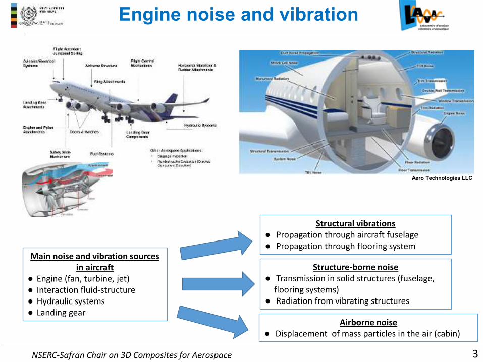
Engine noise and vibration
3
Aero Technologies LLC
Main noise and vibration sources
in aircraft
● Engine (fan, turbine, jet)
● Interaction fluid-structure
● Hydraulic systems
● Landing gear
Structural vibrations
● Propagation through aircraft fuselage
● Propagation through flooring system
Structure-borne noise
● Transmission in solid structures (fuselage,
flooring systems)
● Radiation from vibrating structures
Airborne noise
● Displacement of mass particles in the air (cabin)
NSERC-Safran Chair on 3D Composites for Aerospace 4
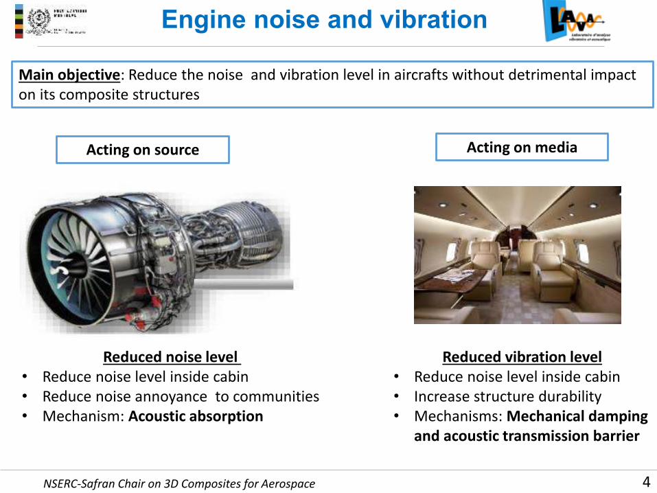
Engine noise and vibration
Acting on source Acting on media
Main objective: Reduce the noise and vibration level in aircrafts without detrimental impact
on its composite structures
Reduced vibration level
• Reduce noise level inside cabin
• Increase structure durability
• Mechanisms: Mechanical damping
and acoustic transmission barrier
Reduced noise level
• Reduce noise level inside cabin
• Reduce noise annoyance to communities
• Mechanism: Acoustic absorption

NSERC-Safran Chair on 3D Composites for Aerospace
Development process
5
Develop
solutions
for
materials &
structures
Fabrication
Testing
Modeling
Analysis
Start from the beginning:
● Define the problem quantitatively
● Understand the needs and context
● Limit the domain
● Define statement of work
● Identify people
(Controlled goods)
Investigation:
● Define requirement specifications
● Understand technical parameters
● Use knowledge and expertise
● Explore innovative ideas
Small scale development:
● Fabricate lab demo samples
● Test preliminary concepts
● Select solution concepts
● Model concept and optimize
● Validate final concept
Implementation:
● Check for air worthiness
● Check for certification
● Evaluate impact on performance
● Develop integration procedures
● Complete proof of concept

NSERC-Safran Chair on 3D Composites for Aerospace
Micro-Characterization
6
NSERC-Safran chair on 3D composites for aerospace
Micro-characterization
thermosets
Mechanical and
dynamic testing
Manufacturing
and prototyping
RheometerHP TGA-FTIR
spectrometer
DMA MDSC
DMA-450 Metravib
Pressclave with acquisition system

NSERC-Safran Chair on 3D Composites for Aerospace
Acoustics/vibration
7
Laboratory for acoustic and vibration analyses (LAVA)
Vibration Acoustics Vibro-acoustics
Reverberation chamber 0,8 m3
Anechoïc room:
4,3 x 4,6 x 3,5 m3
Tube à impédance
Absorption + Transmission

NSERC-Safran Chair on 3D Composites for Aerospace
Additive manufacturing
8
Laboratory of multiscale mechanics (LM2)
UV-LED
Fiber optic
UV radiated zone
Container filled with UV-curable
ink
Self-supporting
microstructure
UV assisted freeform 3D printing(L. Laberge Lebel)
3D printing of complex
microstructures(Lewis, White, U of Illinois at Urbana-
Champaign)
Continuous layer-by-layer
deposition of functional
materials (US Patent 8,101,139,
Therriault et al.)
NSERC-Safran Chair on 3D Composites for Aerospace
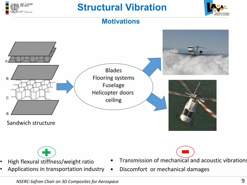
Structural Vibration
9
Sandwich structure
Blades
Flooring systems
Fuselage
Helicopter doors
ceiling
• High flexural stiffness/weight ratio
• Applications in transportation industry
• Transmission of mechanical and acoustic vibrations
• Discomfort or mechanical damages
Motivations

NSERC-Safran Chair on 3D Composites for Aerospace
Structural Vibration
10
Passive damping
CLD
Base layerConstraining layer Damping layer
Damping increase through energy dissipation
Constrained layer damping (CLD)
Partial constrained layer damping (PCLD)
Shearing of viscoelastic material through flexural
motion of the structure
NSERC-Safran Chair on 3D Composites for Aerospace
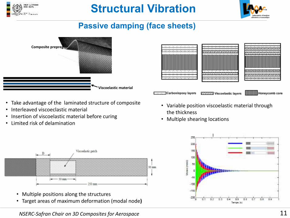
Structural Vibration
11
Passive damping (face sheets)
Viscoelastic material
Composite prepreg
• Take advantage of the laminated structure of composite
• Interleaved viscoeclastic material
• Insertion of viscoelastic material before curing
• Limited risk of delamination
• Variable position viscoelastic material through
the thickness
• Multiple shearing locations
• Multiple positions along the structures
• Target areas of maximum deformation (modal node)

NSERC-Safran Chair on 3D Composites for Aerospace
Structural Vibration
12
Experimental vs model
Increase of damping ratio at the modal nodes
Fotsing et al, Lightweight viscoelastic damping treatment of composite sandwich beams: experimental analysis, Journal of composite materials, 47 (12) 2013 , 1501-1511

NSERC-Safran Chair on 3D Composites for Aerospace
Structural Vibration
13
Passive damping (core)
Risk of altering locally the mechanical properties of the structure
• Increase of structural damping
• Increase of acoustic transmission loss
• Reduction of the added mass
• Core stiffness modification
• Cells filled with viscoelastic materials
• Embedded damping device in the core
• Metamaterials in the core
Mapping of the whole structure along the
nodal lines (high shear deformation)

NSERC-Safran Chair on 3D Composites for Aerospace
Structural Vibration
14
Modelling of passive damping
Sandwich structure
Assumed modes method
Total energy (kinetic and potential)
Harmonic response
Eigenvalue problem
Natural frequencies Damping
Core
Displacement field
Deformation
Stresses
Energies
Viscoelastic material
Displacement field
Stresses
Energies
Skins
Top skin Bottom skin
Displacement field
Deformation
Stresses
Energies
Mo
de
llin
gR
eso
luti
on

NSERC-Safran Chair on 3D Composites for Aerospace
Engine noise
15
MotivationsLow-Bypass Ratio engine
High-Bypass Ratio engine
• Engine length reduced
• Nacelle diameter increased
• Areas for acoustic treatment narrowed
• Several sources of noise
• Fan noise important during take-off and landing
• Annoyance to communities around airports
• Discomfort for passengers
• Reduced durability of the structures

NSERC-Safran Chair on 3D Composites for Aerospace
Engine noise
16
Locally reacting acoustic liner (Helmholtz resonators)
• Target only one octave band centered on fan blade passage frequencies
• Not suitable for critical areas such as OGVs
• Too cumbersome and heavy
• Development possibilities exhausted
• Need for new technologies breakthrough
• Development of new absorbing materials
• Development of new acoustic concepts
• Development of new integration procedures
NSERC-Safran Chair on 3D Composites for Aerospace
Absorbing materials
17
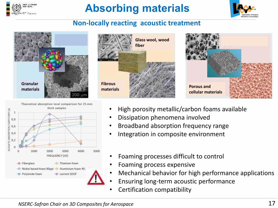
Non-locally reacting acoustic treatment
• High porosity metallic/carbon foams available
• Dissipation phenomena involved
• Broadband absorption frequency range
• Integration in composite environment
• Foaming processes difficult to control
• Foaming process expensive
• Mechanical behavior for high performance applications
• Ensuring long-term acoustic performance
• Certification compatibility
Granular
materials
Fibrous
materials
Glass wool, wood
fiber
Porous and
cellular materials
NSERC-Safran Chair on 3D Composites for Aerospace
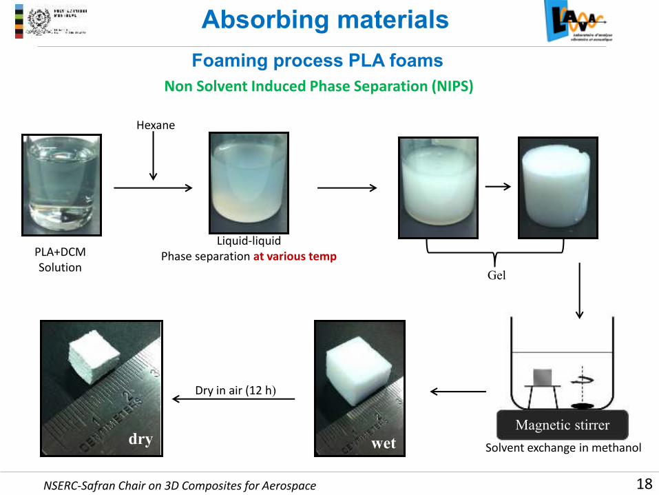
PLA+DCM
Solution
Hexane
Liquid-liquid
Phase separation at various temp
Gel
Magnetic stirrer
Dry in air (12 h)
wetdrySolvent exchange in methanol
Absorbing materials
Foaming process PLA foams
Non Solvent Induced Phase Separation (NIPS)
18

NSERC-Safran Chair on 3D Composites for Aerospace
Porosity = 45%
Compressive Strength = 45 MPa
13 wt.% @ room temperature 23 wt.% @ room temperature
Porosity = 84%
Compressive Strength = 8 MPa
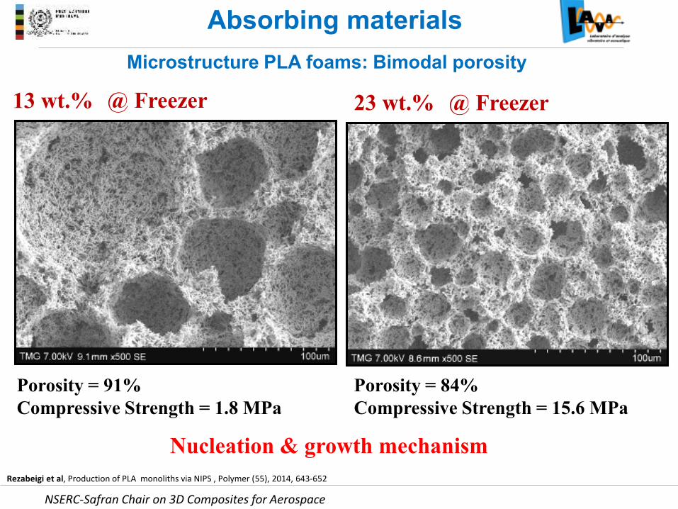
Microstructure PLA foams: Bimodal porosity
Absorbing materials
Rezabeigi et al, Production of PLA monoliths via NIPS , Polymer (55), 2014, 643-652
NSERC-Safran Chair on 3D Composites for Aerospace
Nucleation & growth mechanism
13 wt.% 23 wt.%
Porosity = 91%
Compressive Strength = 1.8 MPa
@ Freezer @ Freezer
Porosity = 84%
Compressive Strength = 15.6 MPa
Microstructure PLA foams: Bimodal porosity
Absorbing materials
Rezabeigi et al, Production of PLA monoliths via NIPS , Polymer (55), 2014, 643-652

NSERC-Safran Chair on 3D Composites for Aerospace
Microstructure PLA foams: Bimodal porosity
Absorbing materials
Rezabeigi et al, Production of PLA monoliths via NIPS , Polymer (55), 2014, 643-652
Crystallization of PLA23 wt.%@ Freezer
13 wt.%@ Freezer
NSERC-Safran Chair on 3D Composites for Aerospace
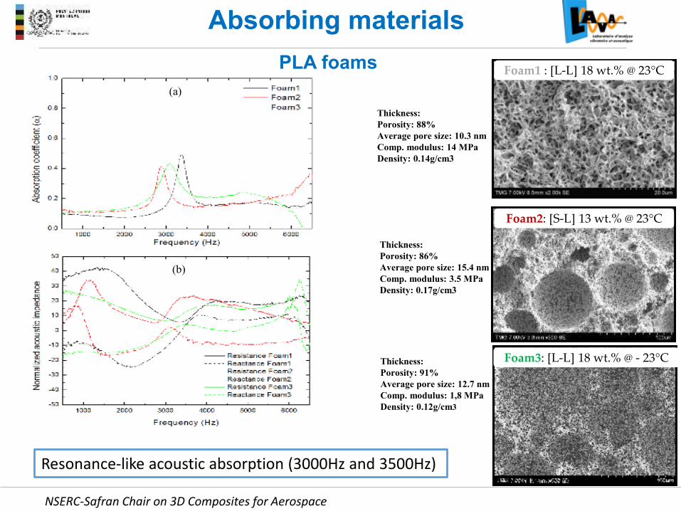
Foam1 : [L-L] 18 wt.% @ 23°C
Thickness:
Porosity: 88%
Average pore size: 10.3 nm
Comp. modulus: 14 MPa
Density: 0.14g/cm3
Foam2: [S-L] 13 wt.% @ 23°C
Foam3: [L-L] 18 wt.% @ - 23°C
(a)
(b)
Absorbing materials
Resonance-like acoustic absorption (3000Hz and 3500Hz)
Thickness:
Porosity: 86%
Average pore size: 15.4 nm
Comp. modulus: 3.5 MPa
Density: 0.17g/cm3
Thickness:
Porosity: 91%
Average pore size: 12.7 nm
Comp. modulus: 1,8 MPa
Density: 0.12g/cm3
PLA foams

NSERC-Safran Chair on 3D Composites for Aerospace
Absorbing materials
• Interesting transmission capabilities at low frequency
• Can be used as absorbing material and sound barrier
PLA foams Foam1 : [L-L] 18 wt.% @ 23°C
Foam2: [S-L] 13 wt.% @ 23°C
Foam3: [L-L] 18 wt.% @ - 23°C
Fotsing et al, Acoustic properties of porous PLA monoliths produced via NIPS, ICTAM 2016 (Montreal)

NSERC-Safran Chair on 3D Composites for Aerospace
Absorbing materials
24
Foam #1 Foam #2
• Porosity greater than 85 % (ideal for acoustic treatment)
• Improved mechanical properties (up to 50 MPa compressive modulus)
• Porosity gradient through the thickness (ideal for non-locally acoustic treatment)
• Easy integration to composite structures (e.g. sandwich structures)
Innovative process to produce thermoset foams
• Simple and flexible
• Cost effective
• Fully controllable
Thermoset foams
1000 μmCommercial metallic foam (Recemat)

NSERC-Safran Chair on 3D Composites for Aerospace
Absorbing materials
25
• Epoxy foam slightly more resistive than the metallic foam
• Absorption on a broad frequency range for epoxy foam
Thermoset foams
NSERC-Safran Chair on 3D Composites for Aerospace
Absorbing materials
26
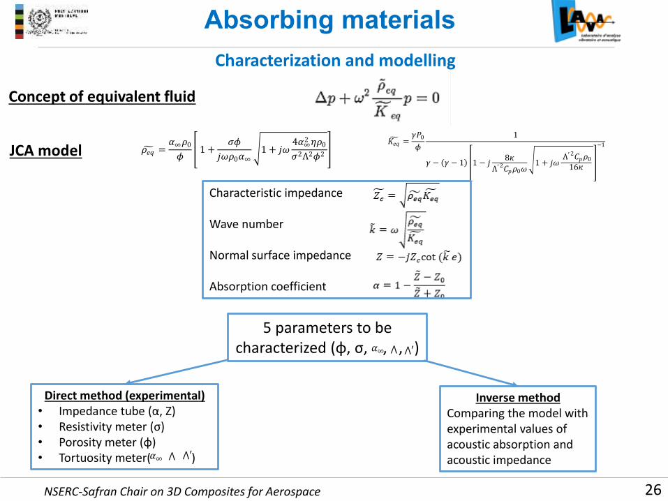
Characterization and modelling
Concept of equivalent fluid
𝜌𝑒 =𝛼∞𝜌0𝜙 1 +
𝜎𝜙𝑗𝜔𝜌0𝛼∞ 1 + 𝑗𝜔 4𝛼∞2 𝜂𝜌0𝜎2Λ2𝜙2 ,
𝐾𝑒 =𝛾𝑃0𝜙 1
𝛾 − 𝛾 − 1 1 − 𝑗 8𝜅Λ′2𝐶 𝜌0𝜔 1 + 𝑗𝜔 Λ′2𝐶 𝜌0
16𝜅 −1
JCA model
Characteristic impedance
Wave number
Normal surface impedance
Absorption coefficient
⋀ ⋀′ 𝛼∞
Direct method (experimental)
• I peda e tu e α, Z • Resistivity meter σ)
• Porosity meter φ • Tortuosity meter( )
Inverse method
Comparing the model with
experimental values of
acoustic absorption and
acoustic impedance
5 parameters to be
hara terized φ, σ, , , 𝛼∞ ⋀ ⋀′

NSERC-Safran Chair on 3D Composites for Aerospace
Conclusion
27
Implement acoustic absorption solutions
● Lightweight
● Non intrusive
● High performance
● Cost effective
Implement sound barrier solutions
● Lightweight
● Non intrusive
● High performance
● Cost effective
Implement mechanical damping solutions
● Lightweight
● Non intrusive
● High performance
● Cost effective
Implement
functionalities
to
existing structures
at the
design stage
Innovative concepts
No corrective
patches !

NSERC-Safran Chair on 3D Composites for Aerospace
Thank you
28