noise in modulation systems - vlsi signal processing lab, ee, nctu
TRANSCRIPT

Principles of Communications I (Fall, 2007) Noise in Modulation Systems
NCTU EE 1
Noise in Modulation Systems SNR — Signal-to-Noise Ratio:(S/N)
One of the most important parameters in communication systems. (The other is B.W.)
point certaina at
powernoisepowerSignalSNR =
channel model:additive, white, Gaussian noise with power
(AWGN) (independent of signal)
spectral density 2
0N
N0 / 2
Receivermessage+
+ A B
n(t) noise
signal(containingmessage)
Compare different receiver (modulation): Assume the same “SNR” at A, which one has better SNR at B.
【Note】:The power spectral density is 2
0N . ( some books use 0N )
Physical meaning: 0N is the average noise power per unit bandwidth
(single-sided psd) at the front end of the receiver.

Principles of Communications I (Fall, 2007) Noise in Modulation Systems
NCTU EE 2
Noise in Linear Modulation Baseband model:a basis for comparison.
Message signal power = TP (watts) (transmitted power)
At the filter input
BNdfNB
B 0021
=∫− , BNP
SNR Ti
0
)( =
At the filter output
WNdfNW
W 0021
=∫− , WNP
SNR To
0
)( =
SNR enhancement WB
SNRSNR
i
o =)()(
This is a basic assumption in many communication system:
we, at least, filter out the out-of-band noise. (This filtering usually does not change signal (power)). 【Note】:The signal power is often referred to the “transmitted” signal.
(not message itself) (modulated)

Principles of Communications I (Fall, 2007) Noise in Modulation Systems
NCTU EE 3
A. DSB-SC Systems:Coherent Detection
xr(t) = xc(t) + n(t) Post det. LF
A
2 cos(wct + q )
yD (x)e3 (x)e2 (x) Predetection filter
( BPF )
f0 fc- fc
BPF
2W2W
N0 / 2
SXc(f)
0 f
LPF
fc 2 fc-2fc - fc2W
f
++= )cos()()( θtwtmAtx ccr n(t) white noise
BPF passing through BP noise
)sin()()cos()()cos()()(2 θθθ +−+++= twtntwtntwtmAte cscccc
Noise power: WNtntntn sc 0222
0 2)(21)(
21)( =+=
pass band
Signal power: )(2
22
tmAc
Predetection SNR:0
22
4)(
WNmASNR c
T =
)cos(2)()( 23 θ+⋅= twtete c
))(2sin()())}(2cos(1){())}(2cos(1){( θθθ +−+++++= twtntwtntwtmA cscccc
↓LPF
)()()(0 tntmAty cc +=

Principles of Communications I (Fall, 2007) Noise in Modulation Systems
NCTU EE 4
Noise power: WNtnc 02 2)( =
Signal power: 22 mAc
Postdetection SNR:WN
mASNR cD
0
22
2)( =
)3(2)()(gain Detection dB
SNRSNR
T
D ===Δ
Does this detection (demodulation) provide a 3dB gain? Not quite
(1) What is the “equivalent” baseband system?
22
0 21power dtransmitte mA
WNP
cT =←=γ
Dc SNR
WNmA )(
2 0
22
==
(2) Why? The baseband noise is )(0 WBwWN =
The passband noise is )2(2 0 WBwWN =
The detection gain cancels the noise BW increase.
【Note】:We assume coherent detection, i.e., the LO signal )cos( θ+twc
has the same cw and θ as the carrier.

Principles of Communications I (Fall, 2007) Noise in Modulation Systems
NCTU EE 5
B. SSB System:Coherent Detection
m of ans.Hilbert trˆ where)()]sin()(ˆ)cos()([)( :Signal Received
:mtnwtmtwtmAtX cccr ++±+= θθ
Demodulation:
ffcfc-w0-fc+w-fc fw0-w
xr(t)
2 cos(wct + θ )
yD (x)e3 (x)e2 (x)BPF LPF
<Key>:Decompose noise into in-phase and guadrature components
(BP noise!)
noiseBP
NLet
)sin()()cos()()(
0222
0
↑
====
+−+=Δ
WNnnn
twtntwtntn
scT
cscc θθ
Thus,
term.noise)()()(LPF e
)cos(2* caret don'
)sin()]()(ˆ)cos()]()([)(
3
2
←+=→↓
+↑↓
+±++=
tntmAty
tw
twtntmAtwtntmAte
ccD
c
cscccc
θ
θθ m
NOISE
Lower-Sideband
ffcfc-w
N0 / 2
Upper-Sideband
coherent
Principles of Communications I (Fall, 2007) Noise in Modulation Systems
NCTU EE 6
Assume m(t) is independent of ).(tnc
Post-detection signal power: )( 22 mAS cD =
Post-detection noise power: WNnN cD 02 )( ==
Post-detection WNmASNR c
D0
22
=
What is transmitted signal power (Predetection)
TDc
c
cc
ccc
cc
ccccc
cccT
PStmA
tmtmtmtmA
twtw
twtmtwtmA
twtwtmtmtwtwtmtmtwtmtwtmA
twtmtwtmAS
===
=+=
⟩+−⟨⟩++⟨
↓↓
⟩+⟨+⟩+⟨=
++−+++=
+−+=
!))((
))(ˆ)(( })(ˆ21)(
21{
)2cos(21
21 )22cos(
21
21
)(sin)(ˆ)(cos)({
.)orthogonal are )sin( and )cos( ( .)orthogonal are )(ˆ and )( ( )sin()cos()(ˆ)(2)]sin()(ˆ[)]cos()([{
)]}sin()(ˆ)cos()([{
22
22222
22222
222
2
θθ
θθ
θθθθ
θθ
∴ Detection gain:
TD
T
T
D
D
T
D SNRSNR
WNNS
NS
SNRSNR
==
=
= 1
)()()(
0
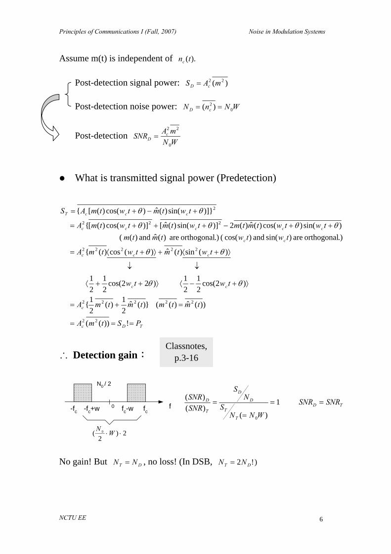
No gain! But DT NN = , no loss! (In DSB, )!2 DT NN =
Classnotes, p.3-16
ffc-fc+w
N0 / 2
-fc fc-w0
2)2
( 0 ⋅⋅WN

Principles of Communications I (Fall, 2007) Noise in Modulation Systems
NCTU EE 7
C. AM System:Coherent Detection
Received Signal:
message normalized: index modulation: )cos()](1[)(
n
cncc
matwtamAtx θ++=
ffc-fc fc+w0
carrier
Mn(f)
fW0-W
X 2 cos(wct + θ )
e2 (x)
e3 (x)
BPF
xr(t) = xc(t) + n(t)
LPF
yD(t) = Ac a mn(t) + nc(t) + Ac Ac is removed
it. removesimply weThus, .)( of termdcrecover cannot wereality, In 2) term)(dc term;dc remove thuscan we,0)( assume )1 removed is
tmtmAc =Q
Post detection signal power: 2222))(( ncncD maAtamAS ⋅==
Post detection noise power: WNnN cD 02 2==
WNmaA
SNR ncD
0
222
2)( =
f
N0 / 2
fc-w0
WWN0
0 2N2)22
( =⋅⋅
fc+w

Principles of Communications I (Fall, 2007) Noise in Modulation Systems
NCTU EE 8
) )cos(221)(cos , )((
)(cos)()(cos
)}cos()](1[{:power signalTx
222
222222
2
θθ
θθ
θ
++=+=
+⋅++⋅=
++=•
ccnn
cnccc
cncT
wwmtm
wtmaAwA
wtamAS
2222
21
21
nccTT maAASP +==
BP noise power: WNNT 02=
Pre-detection WN
maAASNR nccT
0
2222
221)( +
⋅=
∴ Detection gain:
1)(loss!1
2
)(21)(
)(22
22
2222
222
<+
=+
=n
n
ncc
nc
T
D
mama
maAA
maASNRSNR
Recall, (power) Efficiency: 22
22
1 n
nff
mamaE
+=
ffT
D ESNRSNR 2
)()(
=∴
【Note】WN
PEWN
PESNRESNR Tff
TffTffD
00
2
2)(2)( =⋅=⋅=
Ex: 2nm =0.1 a=0.5 0244.0
1.0)5.0(11.0)5.0(
2
2
=⋅+
⋅=ffE
Detection gain = 2Eff = 0.0488!
ffc-fc0

Principles of Communications I (Fall, 2007) Noise in Modulation Systems
NCTU EE 9
D. AM System:Envelope Detection
xr(t) yD (x)e2 (x)BPF Envelope
detector
WNnn
twtntwtntwtamAtn
txtntxte
sc
cscccnc
cc
022
0
02
2)()( :Noise
)sin()()cos()()cos()](1[ noise band-narrow:)(
signal modulated:)( )()()(
==
+−++++=
+=
θθθ
f
N0 / 2
0 fc-fc
))()](1[
)((tan)(
)()}()](1[{)(
)](cos[)()(
1
22
2
{tntamA
tnt
tntntamAtr
ttwtrte
cnc
s
scnc
c
++=
+++=
++=→
−φ
φθ
Phasor diagram:
Letθ=0 ( θ does not affect envelope demod.)
Recall what we did forinterference φ(t)
ns(t)r(t)
nc(t)Ac(t) [ 1+aMn(t) ]
Ideally, average:)( )()()(
carrier) the(including dc remove (envelope)
amplitude )()('
trtrtrty
trty
D
D
−=
↓
=

Principles of Communications I (Fall, 2007) Noise in Modulation Systems
NCTU EE 10
Case 1: TSNR)( is large. i.e., small noise.
)decreased.(neither increasednot is noise -detectioncoherent as same
)()()(mean zero
time theofmost )()](1[)()()()](1[
↑
+≅⇒
↑↑
++≅⇒
>>++
tntamAty
tntamAtrtntntamA
cncD
cnc
scnc
Case 2: TSNR)( is small. i.e., large noise.
φ(t)
rn(t)
φn Ac(t) [ 1+aMn(t) ]
r(t)
[ ] nncn φ(t)aMArr(t) cos1++≈
Bandpass noise: ))(cos()()(0 ttwtrtn ncn φ+=
Thus,
))(cos()( importantnot is ))(cos()()cos()](1[)(2
ttwtrttwtrtwtamAte
nc
ncncnc
φψθθφθ
++=+++++=
Now, assume timeofmost )()](1[ trtamA nnc <<+
)()(cos)](1[)()(
dc"" remove
)(cos)](1[)( )](sin)](1([)](cos)](1[)([)( 22
trttamAtrty
ttamAtrttamAttamAtrtr
nncnD
nncn
nncnncn
−++≅
↓
++≅
++++=
φ
φφφ
Remove “dc”

Principles of Communications I (Fall, 2007) Noise in Modulation Systems
NCTU EE 11
Recall:
0 rn
fRn(rn)
r
n(t) =
nc(t)
ns(t)
rn(t)
where nc(t) and ns(t) are all independent zero mean Gaussian
lost! is message
random:)(cos )(cos)](1[)(~)( Now,distr.-Rayleigh)()()( 22
tttamAtrtrtntntr
nnncn
scn
φφ++
=+=
What we try to show here is that when noise > (message) signal, “noise” becomes the dominate output component. In the output signal, no message signal is proportional to the message signal.
(cf. Coherent detection: )()()( tamAtnty nccD += )
(Recall: The analysis in interference.) This is the threshold effect.
( ∵The envelope detector is nonlinear,
∴the message is “lost” when SNR< threshold )
Remark:It’s difficult to calculate the exact (SNR)D.
Def. of threshold:
A value of the carrier-to-noise ratio (or SNR) below which the noise
performance of a detector deteriorates much more rapidly than
proportionately to the carrier-to-noise ratio (or SNR).
Haykin, p.325

Principles of Communications I (Fall, 2007) Noise in Modulation Systems
NCTU EE 12
E. AM System: Square-Law Detection.
──An example of simple nonlinear detector that we can calculate
SNR and thus the “threshold region” can be more precisely
determined.
xr(t) yD (x)e2 (x)BPF Remove
dc( )2yD'(x)
LPFe3 (x)
~2W
)sin()()cos()()cos()](1[ noise bandpass:)( )()( '
0'02
twtntwtntwtamAtntnxte
cscccnc
c
−++=+=
) freq. high : )2cos( ),2(sin (
)]2cos(21
21)[()2sin()()}( )](1[{
)]2cos(21
21[)}()](1[{
)(sin)()sin()cos()()}( )](1[{2
)(cos)}()](1[{ )()(
2
2
22
22223
twtw
twtntwtntntamA
twtntamA
twtntwtwtntntamA
twtntamAtete
cc
cscscnc
ccnc
csccscnc
ccnc
−+⋅++
−+++=
+⋅⋅++
−++==
LPF
)()()()(2)(2)()(2 )envelope( )(
)()}()](1[{)(
2222222
22
22'
tntntntamAtnAtmaAtamAAtr
tntntamAty
sccncccncncc
scncD
++++++=
==
+++∝

Principles of Communications I (Fall, 2007) Noise in Modulation Systems
NCTU EE 13
)()()()()()(2
)(2])()([)(2)(
message
0)()( ,0)( )()(
2222
22222
dc remove'
tntntntntntamA
tnAtmtmaAtamAty
tntntmtyty
sscccnc
ccnncncD
scnDD
−+−+
++−+=
↓
===⎯⎯⎯ →⎯
)(4:power Signalion Postdetect 224ncD maAS =
224224
22222244
)()()()(
)](1[4]))([( :power Noise ionPostdetect
sscc
cncnncD
nnnn
ntamAmtmaAN
−+−
+⋅++−=
⎥⎦⎤
⎢⎣⎡ −=+⋅−=− )()()(2)()(
22422224222 xxxxxxxx
(Assume the cross terms are either zero or can be neglected)
Note: 224 )(3)( cc nn ⋅= , if cn is Gaussian.
This can be shown using moment generator )(2
22
tet
θσ
=
WNnn nsc 0222 2)()( === σ .
44222222244 22)1(4])[( nnnncnncD maAmmaAN σσσ +⋅+⋅++−=
4222222244
224
4)1(4)(
4)(
nnncnnc
nc
D
DD
maAmmaA
maANS
SNRσσ +++−
==

Principles of Communications I (Fall, 2007) Noise in Modulation Systems
NCTU EE 14
Example:
81)]2cos(
21[
]21)([cos))((
signal randoma not )cos()(
2
2222n
2n
==
−=−
←=
tw
twmtm
twtm
m
m
mn
If we assume this part can be neglected, (to be discussed below)
4222 4)211(4 nncD aAN σσ ++=
)161(
81 :power Its
noise. random-not -.distortion harmonic called is ))cos(2 ( termThe )()()()()()]cos(1[2
)2cos(21)cos(2)(
)2cos21
21cos (
)()()()]cos(1[2 dc remove
)]([cos)cos(2)( )( and )( examine weIf :Note
244
m
2222
222
2
22
22222'
'
DcD
sscccmc
mcmcD
mm
sccmc
mcmccD
DD
SaaAD
twtntntntntntwaA
twaAtwaAty
twtw
tntntntwaA
twaAtwaAAtytyty
⋅==
−+−+⋅+
++=
+=
++⋅+↓
+++=
Now, 2424224 2
2144 aAaAmaAS ccncD =⋅==
)(2)2(4)2(2
2)(2
22
2
22
4222
24
c
n
n
c
nnc
cD
Aa
aA
aAaASNR
σσ
σσ ++=
++=
compare: “Baseband” system: WN
PT
0
=γ
)cos(w
)211(
21)1(
21)}cos()](1[{
m
222222
t
aAmaAtwtamAP cnccncT
↑
+=+=⋅+=

Principles of Communications I (Fall, 2007) Noise in Modulation Systems
NCTU EE 15
Now, r
ra
a
PWNWN
P
aaSNR
T
T
D ++=
++=
1)
2(2
)(1)
2(2)( 2
20
022
( WNn 02 2=σ )
)2
(2)( ,1 If
0
0
22
0
WNP
E
WNP
aaSNR
WNP
T
TD
T
≅
⋅+
≅>>
( similar to the coherent case )
) small is when,(.) (
)1( )()2
(2)( ,1 If
00
002
0
22
0
WNP
WNP
PWN
PWN
WNP
aaSNR
WNP
TT
TT
TD
T
⋅<<
≈+⋅+
≅<< Q
This illustrates threshold effect.
Remarks﹔
1) The performance of envelope detector is better than that of square
law detector for high SNR and a=1. (by 8.1≈ dB)
2) The B.W. of )(2 tnc is wider than W and thus part of it can be
filtered out by LPF. =

Principles of Communications I (Fall, 2007) Noise in Modulation Systems
NCTU EE 16
General form:(assume 4222 )( amm nn ⋅− is small)
T
T
n
nT
T
c
T
nn
c
T
nn
c
n
nnnc
n
nc
D
n
n
cncncT
nnnc
ncD
PWNWN
P
ma
maWN
PWNP
EA
P
EA
P
EA
mamaA
mamaA
SNR
ma
maE
twtamAmaAP
maA
maASNR
0
0
222
22
00
2
42
2
42
2
22
42222
22
224
22
22
2222
42222
224
1)1(21
41
21
21
21
)1(4)1(4
)1(4
)(
1
))}cos()](1[{( )1(21
4)1(4
4)(
+⋅
+=⋅
+
⋅=
+
⋅=
+
⋅=
+++
+=
+=
⋅+=+=
++=
σσσσσσ
σσ
WNP
mamaSNRWNP T
n
nDT
0222
22
0)1(
)( , If ⋅+
≈>>
2
0222
22
0 )()1(
)( , IfWN
Pma
maSNRWNP T
n
nDT ⋅
+≈<<
Special case: 212 =nm

Principles of Communications I (Fall, 2007) Noise in Modulation Systems
NCTU EE 17
Noise and Phase Errors in Coherent Systems -- Random noise and carrier phase error combined effect.
General signal model: (recall: at the same carrier frequency, we can transmit two “separate” messages – quadrature representation).
ttmttmtx ccc ωω sin)(cos)()( 21 +=
(quadrature double-sideband QDSB)
Special cases:
(1) DSB: ⎩⎨⎧
==
0)()()(
2
1
tmtmtm
(2) SSB: ⎩⎨⎧
±==
)(ˆ)( )()(
2
1
tmtmtmtm
Narrowband noise: Tsc BNnn 022 ==
ttnttntn cscc ωω sin)(cos)()( −=
Receiver local carrier:
))(cos(2 ttc φω + )(tφ : Gaussian, mean = 0, variance = 2φσ
( phase error )
Note: A constant θ can be inserted to all the above three terms → same results
Principles of Communications I (Fall, 2007) Noise in Modulation Systems
NCTU EE 18
Goal: compute (random) demodulation error statistics (t)(t)-ymε D1=
⎩⎨⎧
===
? 0
21
2 }(t))(t)-yE{(mε D
ε
(1) ttnttnttmt(t)mte cscccc ωωωω sin)(cos)(sin)(cos)( 21 −++=
(2) )(sin))()(()(cos))(()( 21 ttntmttn(t)mty scD φφ −−+=
(3) Error
)(sin))()(()(cos))()(()()()( 2111 ttntmttntm(t)mtytmt scD φφε −++−=−=
φφφ
φφφε22
221
2212111
21
2
sin)(cossin))((2
cos)(sin)(2cos)(2
ssc
csc
nmnmnm
nmnmmnmmm
−+−+−
++−++−=
Assume: m1, m2, nc, ns and φ are all uncorrelated.
φφφφ coscoscoscos)( 211
2111 ⋅=+=+∴ mnmmnmm cc
(4) 2222
221
21
21
2 sincoscos2 nmmmm +⋅+⋅+⋅−= φφφε
Tnsc BNnnn 02222 ==== σ

Principles of Communications I (Fall, 2007) Noise in Modulation Systems
NCTU EE 19
Case A: QDSB and 222
21 mmm σ== (equal power message);
WBT 2=
222
22222222
cos22
)sincos(cos2
nmm
mnmmQ
σφσσ
φφσσφσσεε
+⋅−=
+++⋅−==
Assume )(211)(cos1)( 2 ttt φφφ −≈⇒<<
22
211)(
211cos φσφφ −=−≈⇒ t
2222nm σσσε φ +≈
multiplicative additive (phase error) (white channel noise)
After normalization
2
222
m
nNQ σ
σσε φ +≈
Principles of Communications I (Fall, 2007) Noise in Modulation Systems
NCTU EE 20
Case B: SSB ⎩⎨⎧
±==
)(ˆ)( )()(
2
1
tmtmtmtm
, WBT =
222
21 mmm σ== , m1(t) and m2(t) are orthogonal
2222 cos22 nmms σφσσε +⋅−=
But WNn 02 =σ ( not 2N0W )
Thus 2
22 )cos1(2
m
nNS σ
σφε +−≈
For 1)( <<tφ , 2
222
m
nNS σ
σσε φ +≈
⇒ same result as QDSB
Case C: DSB ⎩⎨⎧
==
0)( )()(
2
1
tmtmtm
, WBT 2=
222
222222
)cos1(
coscos2
nm
nmmmD
+−⋅=
+⋅+⋅−=
φ
φφε
For 1)( <<tφ , 2
21cos1 φφ ≈−
2422422
43
41
nmnmD σσσσφσε φ +⋅=+⋅≈
( If φ zero-mean, real Gaussian, 224 )(3 φφ = )
2
242
43
m
nND σ
σσε φ +≈

Principles of Communications I (Fall, 2007) Noise in Modulation Systems
NCTU EE 21
<Remarks>
(1) If 02 =φσ ( no carrier phase error )
SNR detectioncoherent 2
22
* ==m
nN σ
σε
(2) DSB is less sensitive to phase error.
For 1)( <<tφ , 24
43
φφ σσ <
Pilot: one technique to reduce phase error
Pilot signal: frequencycarrier cos ⋅=⋅ KtKA cP ω Pilot filter output: (assume AWGN)
)](cos[)(sin)(cos)(cos
ttKtrtKtntKtntKA
c
cscccP
γωωωω
+=⋅−⋅+⋅
phase error: )()(tan)( 1
tnAtntcP
s
+= −γ
where Pcs BNnn 022 ==

Principles of Communications I (Fall, 2007) Noise in Modulation Systems
NCTU EE 22
(1) If AP >> nc , P
s
Atnt )()( ≈γ
TP
s
SNRAn
21
2
22 ==⇒ γσ ( Pilot power = 2
21
PA )
Thus, a strong pilot SNR ensures small phase error.
(2) Frequency divider:
])(cos[2)](cos[21
KttttKw c
frequencyK
cγωγ +⎯⎯⎯ →⎯+
Thus, 22
2 1γφ σσ
K= (noise reduction)
Small Noise in Angle Modulation Ideal angle demodulation system
BW WDBT )1(2 +≈ Hz (Carson’s rule) Received signal:
)()](cos[)()()( tnttAtntxtx cccr ++=+= φω
⎪⎩
⎪⎨⎧
=∫ for FM )(2
for PM )()( t
nd
nP
dmftmK
t ααπφ
n(t): AWGN )(W/Hz 21
0N

Principles of Communications I (Fall, 2007) Noise in Modulation Systems
NCTU EE 23
Output of the predection filter
))(cos()())(cos( sin)(cos)())(cos()(1
tttrttAttnttnttAte
ncncc
cscccc
φωφωωωφω
+++=−++=
Rayleigh dist uniform dist
where Tcs BNnn 022 ==
Reference: )cos( tA cc ω ( if Ac >> n(t) )
Let )()()( ttt n φφθ −=
))()(cos()( ))(sin())()(sin()(
))(cos())()(cos()())(cos( ))()()(cos()())(cos()(1
ttttRtttttr
tttttrttAtttttrttAte
ec
cnn
cnncc
ncncc
φφωφωφφ
φωφφφωφφφωφω
++=+−−
+−++=+−+++=
noise
where ))()(cos()())()(sin()(tan)( 1
tttrAtttrt
nnc
nne φφ
φφφ−+
−= −
Principles of Communications I (Fall, 2007) Noise in Modulation Systems
NCTU EE 24
Output of discriminator: (phase deviation)
)()()( ttt eφφψ +=
(If 0)( =teφ , perfect recovering of message)
Case A: High detection (SNR)T or )(trA nc >> most of the time
))()(sin()())()(cos()(
))()(sin()(tan)( 1 ttA
trtttrA
tttrt nc
n
nnc
nne φφ
φφφφφ −≈−+
−= −
Then, ⎪⎩
⎪⎨⎧ ⋅
= for FM 21
for PM )()(
dtdK
tKty
D
P
D ψπ
ψ
(A.1) PM: )()()()()( tntmKKtKtKty PnPDeDDDP +⋅=⋅+⋅= φφ
where )]()(sin[)(
)()( ttA
trKtKtn n
c
nDeDP φφφ −=⋅≡
signal power (message): 222nPDDP mKKS ⋅=
noise power:
(i) Complete analysis --- 0)( ≠tφ . Difficult!
(note )(teφ depends on )(tφ )
Produce additional terms (frequency components) for f > W at the discriminator output. Can be filtered out. ⇒ Neglect!
(ii) Assume 0)( =tφ
)sin()(sin)( )cos()(cos)()cos()(1
tttrtttrtAte
cnn
cnncc
ωφωφω
−+=
Compare to
)sin()( )cos()()cos()(1 ttnttntAte cscccc ωωω −+=

Principles of Communications I (Fall, 2007) Noise in Modulation Systems
NCTU EE 25
)(sin)()( ttrtn nns φ=⇒ c
sDP A
tnKtn )()( =⇒
02
2
2
2
)()( NAKfS
AKfS
c
Dn
c
DnP s
==⇒
(a) At discriminator output:
Tc
DB
Bc
DDP BN
AKdfN
AKN
T
T 02
22
202
2
== ∫−
(b) At postdetection filter output:
WNAKdfN
AKN
c
DW
Wc
DDP 02
2
02
2
2== ∫−
Transmitting power: 2
2c
TAP =
Post-detection SNRD
WNPmK
WNAmK
AWKNmKK
NSSNR T
nPcnP
cD
nPD
DP
DPD
0
22
0
222
220
222
2/2)( ====
Note: In order to assure unique demodulation.
π≤= deviation phase)(tmK nP
10222 ≈≤⇒ πnP mK
SNR baseband equivalent 0
≡WN
PTQ
⇒ “maximum” improvement = 10.

Principles of Communications I (Fall, 2007) Noise in Modulation Systems
NCTU EE 26
(A.2) FM:
)()()()(21)( tntmfKtn
dttdKty FndDFDDF +=+=
φπ
where )]}()(sin[)(
{2
)(2
)( ttA
trdtdK
dttdK
tn nc
nDeDF φφ
πφ
π−=≡
signal power (message): 222ndDDF mfKS ⋅=
noise power: ( assume 0)( =tφ )
)sin()( )cos()()cos()(1 ttnttntAte cscccc ωωω −+=
)}({2
)}(sin)({2
)( tndtd
AKt
Atr
dtdKtn s
c
Dn
c
nDF π
φπ
==
202
2
02
22
2
)2()2(
)( fNAKNf
AKfS
c
D
c
DnF ==⇒ π
π
At postdetection filter output: 3
02
22
02
2
32 WN
AKdffN
AKN
c
DW
Wc
DDF == ∫−
Transmitting power: 2
2c
TAP =
Post-detection SNRD
Principles of Communications I (Fall, 2007) Noise in Modulation Systems
NCTU EE 27
WNP
mD
WNP
mWf
WNAmf
WNAK
mfKSNR
Tn
Tn
dcnd
c
D
ndDD
0
22
0
223
0
222
302
2
222
3
)(323
32
)(
=
===
where D = deviation ratio Wf
Wdt
td
dt
=≡
)(max
21
φ
π
( )(2)( tmfdt
tdndπφ
≈Q and 1)( ≤tmn )
↑⇒↑⇒↑⇒
≈∴
BW (SNR) D
3t improvemen (SNR)
D
22D nmD
For D >> 1, BT ≈ 2DW (cost)
<Remark> So far, all the above analysis is based on the assumption that Ac >> rn(t) ( high (SNR)T or “above threshold” ).
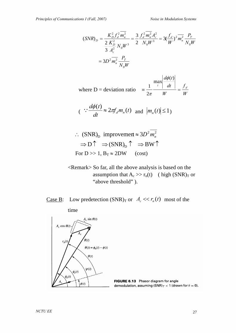
Case B: Low predetection (SNR)T or )(trA nc << most of the
time

Principles of Communications I (Fall, 2007) Noise in Modulation Systems
NCTU EE 28
Let )()()( ttt n φφθ −=
Output of the predetection filter
))(cos()()(1 tttRte c ψω +=
)()(cos)()( trtAtrtR ncn ≈+≈ θ
)]()()[()]()(sin[)()]()(sin[ tttrtttRttA nnnnc ψφψφφφ −≈−=−
)]()(sin[)(
)()( tttr
Att n
n
cn φφφψ −−=⇒
ψ(t) is dominated by noise; message is lost
Threshold Effect!
Preemphasis and deemphasis filter Preemphasis
filter FM
modulator
FM demodulator
Deemphasisfilter
Channel
Noise n(t)
m(t)
m’(t)
Let deemphasis filter = )( fH DE ;
Preemphasis filter = )(
1fH DE
.
Why pre- and de-emphasis? Change the shape of message spectrum before modulation to take the advantage of the nonlinear characheristics of FM noise spectrum.
Principles of Communications I (Fall, 2007) Noise in Modulation Systems
NCTU EE 29
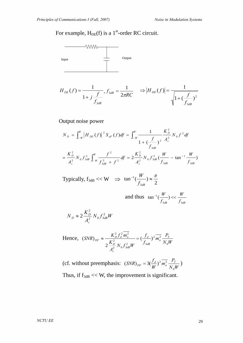
For example, HDE(f) is a 1st-order RC circuit.
Input Output
dB
DE
ffj
fH
3
1
1)(+
= ,RC
f dB π21
3 = 2
3
)(1
1)(
dB
DE
ff
fH+
=⇒
Output noise power
)tan(2
)(1
1)()(
3
1
3
3302
2
223
22
302
2
202
2
2
3
2
dBdBdB
c
DW
WdB
dBc
D
W
Wc
D
dB
W
W nFDED
fW
fW
fNA
Kdf
ff
ffN
A
K
dffNA
K
ff
dffSfHN
−
−
−−
−=+
=
+
==
∫
∫∫
Typically, f3dB << W ⇒ 2
)(tan3
1 π≈−
dBfW
and thus dBdB f
WfW
33
1 )(tan <<−
WfNAK
N dBc
DD
2302
2
2≈
Hence, WN
Pm
ff
WfNAK
mfKSNR T
ndB
d
dBc
D
ndDDF
0
22
32302
2
222
)(2
)( =≈
(cf. without preemphasis: WN
Pm
Wf
SNR Tn
dDF
0
22)(3)( = )
Thus, if f3dB << W, the improvement is significant.

Principles of Communications I (Fall, 2007) Noise in Modulation Systems
NCTU EE 30
Example: FM: fd = 75kHz; W = 15kHz; D = 5; 1.02 =nm
(1) w/o deemphasis:
WNP
SNR TDF
0
5.7)( =
( Note: coherent DSB WN
PSNR T
D0
)( = )
(2) w deemphasis: f3dB = 2.1 kHz
WNP
SNR TDF
0
128)( =
<Remark> Disadvantage of deemphasis: may increase transmission
bandwidth. Deemphasis filter → lowpass filter Preemphasis filter → high filter After preemphasis filter: stronger high frequency components
increase the transmitter deviation wider transmission bandwidth
However, typical message sources have “little” high frequency components.

Principles of Communications I (Fall, 2007) Noise in Modulation Systems
NCTU EE 31
Large Noise in FM --- Thresholds Threshold effect
(SNR)T
(SNR)D Linear model
FM
Probability distribution and PSD of spike noise Zero-crossing probability
A lowpass, zero-mean white Gaussian n(t) Bandwidth W, psd Sn(f) ↔ autocorrelation function Rn(τ)
Let
W21
<<Δ (so that more than one zero-crossing in unlikely)
)0'( )' and 0(
)0)'( and 0( in crossing zero plus-to-minus :
00
000
000
<<Δ−=Δ−><=
>Δ+<=Δ
−Δ
−Δ
nnpnnnpnnnpP
P
Look for all the probability of )',( 00 nn pairs that satisfy the
above conditions.
pdf of )',( 00 nn : ),()',(00 '00 zyfnnf nn=
∫ ∫∞
Δ−−Δ =0
0
' ]),([00
dzdyzyfPz nn

Principles of Communications I (Fall, 2007) Noise in Modulation Systems
NCTU EE 32
0)(}'{0
00 ===ττ
τd
dRnnE nQ
20
2
20
2
0000
'2
2'0
2
20
''2
1
2
1)()(),( n
z
n
y
nnnn en
en
zfyfzyf−−
==ππ
∫
∫
∫ ∫
∞ −
∞ −
∞
Δ−
−−
−Δ
Δ=
ΔΔ≈
=
0
'2
2'0
20
0 20
'2
2'0
0
0 2
20
'2
2'0
2
1
2
small) is (if )(2
1
2
1
]2
1[2
1
20
2
20
2
20
2
20
2
dzzenn
dzzn
en
dzdyen
en
P
n
z
n
z
Z
n
y
n
z
ππ
ππ
ππ
Let 20
2
'2nz
=ζ , 20
20
0
20
20
20
'2
''2 n
ndennn
Pπ
ζπ
ζ Δ=
Δ≈ ∫
∞ −−Δ
(probability of a minus-to-plus zero crossing in Δ seconds )
Example: Lowpass white Gaussian noise
⎪⎩
⎪⎨⎧ ≤
=otherwise 0
21
)( 0 WfNfSn ⇔ )2sinc()( 0 ττ WWNRn =
0)(
0
==ττ
τd
dRnQ ⇒ uncorrelated ⇒ independent
WNRdffSnn nn 0020 )0()(}var{ ==== ∫
∞
∞−
)()2(31
21)2()(2}'var{' 0
20
220
20 WNWdfNfdffSfjnn
W
Wn πππ ==== ∫∫ −
∞
∞−
3)
)2(31
(2
21
0
02
WWN
WNWP Δ
=Δ
=−Δ
π
π
Probability of a zero crossing in Δ =3
2 WPPP Δ=+= +Δ−ΔΔ

Principles of Communications I (Fall, 2007) Noise in Modulation Systems
NCTU EE 33
Average rate of origin encirclement Sinusoid + narrowband Gaussian
)](cos[)( sin)(cos)(cos)(cos)(
0
0000
tttRttnttntAtntAtz sc
θωωωωω
+=−+=+=
where
])(
)([tan)(
)()]([)(
1
22
tnAtnt
tntnAtR
c
s
sc
+=
++=
−θ
Q: How often does this spike happen (on the average)? Probability of R(t) cross the horizontal axis in the 2nd quadrant
in Δ seconds duration PccΔ ≡ counterclockwise encirclement probability = P{A+nc(t) < 0 and ns(t) makes + to – crossing} = P{nc(t) < -A} ⋅ PΔ-
Now, n(t) is a bandpass white Gaussian process Bandwidth = B; psd = N0 (single-side) or N0/2 (double-side)

Principles of Communications I (Fall, 2007) Noise in Modulation Systems
NCTU EE 34
(1) 323
BWP Δ=
Δ=−Δ
(2) )(2
})({0
2
0
2 0
2
BNAQdn
BNeAtnP
A
c
BNn
c
c
==−< ∫−
∞−
−
π
)(32 0
2
BNAQBPcc
Δ=∴ Δ
Similar deduction for PcΔ = clockwise encirclement probability
)(3
)(1
secondper ntsencirclemeofnumber Expected
0
2
BNAQBPP ccc
Δ=+
Δ=
≡
ΔΔ
ν
BNA
BNPSNR T
T0
2
0 2)( == ⇒ ))(2(
3 TSNRQBΔ=ν
If (SNR)T << 1, BB 2887.021
3=
Δ≈ν

Principles of Communications I (Fall, 2007) Noise in Modulation Systems
NCTU EE 35
PSD (pwer spectral density) psd of “periodic” pulsive noise: A random process
∑∞
−∞=
−=k
sk kTtntx )()( δ
and ,....2,1 0)( ±±== kkTR sn (orthogonal)
22 )0(})}({{1lim)( ks
s
nT
sTx nf
TR
txFET
fSs
s
===∞→
For FM spikes, ∑∞
−∞=
−±==k
kttdt
tdtx )(2)()( πδθ
∞<<∞=== fBN
AQBafS kx - )(3
4)2()(0
2222 ππνν
constant for fixed A, N0, and B.
General Case: with message )(])([2cos)( tnttftfAtz c +⋅+= δπ
The spike rate is increased by δν It can be shown (approximately)
BNA
ef 0
2
2−
⋅= δδν
Thus, the total psd is 2)2()()( πδνν ⋅+=fSx
Example: 0constant)( >== dftfδ
Average noise frequency < (fc+fd) signal frequency. ⇒ Noise phasor has more clockwise rotations relative to the
signal power. ⇒ More negative spikes than positive spikes
It can be shown that dff =δ in this case.

Principles of Communications I (Fall, 2007) Noise in Modulation Systems
NCTU EE 36
FM system
dttdK
ty
tttRttnttnttAte
DD
ccscccc
)(2
)(
))(cos()(sin)(cos)())(cos()(1
ψπ
ψωωωφω
=
+=−++=
Now, the spike noise psd = )()2()( 2' δννπψ +=fS
∴ the spike noise psd in yD :
T
c
BNA
DT
cTDDD efK
BNA
QB
KKS 0
2
22
0
222 )(
3)(
−
⋅+=+= δδννδ
( ≈ constant, another “white” noise ( ↑ pulses ))
Noise power:
message todue increase noise spike 2
message no noise, spike )(3
2
Gaussian small 32
0
2
22
0
22
302
2
T
c
BNA
D
T
cTD
c
DD
efWK
BNA
QWBK
WNAK
N
−
⋅+
+
=
δ

Principles of Communications I (Fall, 2007) Noise in Modulation Systems
NCTU EE 37
Signal power: 222ndDD mfKS =
T
c
BNA
T
T
cTT
Tn
d
D
DD
eWN
PW
fBN
AQ
WNP
WB
WNP
mWf
NS
SNR0
2
2
00
2
0
0
22
)(6)()(321
)(3)(
−
++
==δ
Principles of Communications I (Fall, 2007) Noise in Modulation Systems
NCTU EE 38
Key parameters: WN
PT
0
, modulation index DWf d = , fδ
(BT ≈ 2(D+1), Carson’s rule) 3 terms:
(1) small noise ~ 2
0
DWN
PT
(2) spike noise without message ~ DBN
PQ
T
T 1
0
)}2
({ −
(3) spike noise due to message ~ 21}{ 0 DeWf
T
T
BNP
−−δ
If WN
PT
0
is large, spike noise terms (2)(3) ↓ 0.
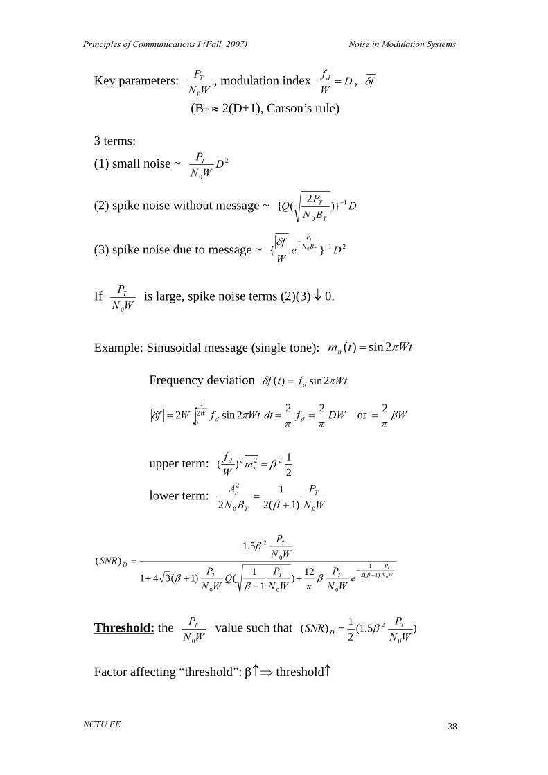
Example: Sinusoidal message (single tone): Wttmn π2sin)( =
Frequency deviation Wtftf d πδ 2sin)( =
WDWfdtWtfWf dW
d βπππ
πδ 2or 22 2sin2 21
0===⋅= ∫
upper term: 21)( 222 β=n
d mWf
lower term: WN
PBN
A T
T
c
00
2
)1(21
2 +=
β
WNP
TTT
T
D T
eWN
PWN
PQ
WNP
WNP
SNR0)1(2
1
000
0
2
12)1
1()1(341
5.1)(
+−
++
++
=ββ
πββ
β
Threshold: the WN
PT
0
value such that )5.1(21)(
0
2
WNP
SNR TD β=
Factor affecting “threshold”: β↑⇒ threshold↑

Principles of Communications I (Fall, 2007) Noise in Modulation Systems
NCTU EE 39
Threshold Extension (spike suppression)
Goal: lower the threshold value (WN
PT
0
)
Methods: (1) Frequency-compression feedback (2) PLL Frequency-compressive feedback (or FM demodulator using feedback)
)](cos[)]()(cos[)( ttwAtttwAtx cceccr ψφφ +=++= message noise
παψ
α 2 )],(
11cos[)( VD
crKK
ttwKtx =+
+=

Principles of Communications I (Fall, 2007) Noise in Modulation Systems
NCTU EE 40
The bandwidth of x(t) (= BP) is reduced by a factor of α+1
1 .
Hence, at the discriminator output:
(i) Signal (message) power reduced by 2)1
1(α+
(ii) Additive Gaussian noise power reduced by 2)1
1(α+
(iii) Spike noise power reduced “exponentially”.
P
c
BNA
P
CP efBN
AQB0
2
2
0
2
)(3
−
⋅+=+ δδνν
∴ Spike noise is significantly reduced. However, the (SNR)D at the post-detector output remains the same as before.
( Q Both SD and ND are reduced by 2)1
1(α+
. )
Noise in Pulse Code Modulation PCM (pulse code) Total error = quantization error “+” channel error (1) Quantization error:
Assume uniform quantizer with stepsize = S. Further assume the quantization error ε(t) is uniformly distributed.
2
2
2
2
22
2
22
1212
)(
121
Sm
SmSNR
SdxS
x
Q
S
S
==
== ∫−ε
(2) Channel error:
One PCM sample = n binary pulses (bit) Bit error probability = Pb Word error probability = any bit is wrong = 1 – (1-Pb)n=Pw

Principles of Communications I (Fall, 2007) Noise in Modulation Systems
NCTU EE 41
Assume q levels, any bit error leads to
qSqS w 21
21
≤≤− ε
Assume wε is uniformly distributed over )21,
21( qSqS− .
2222
121
121 SSqw >>=ε
Total PCM noise power (quantization error is independent of channel error)
wwwD PPN 22 )1( εε +−=
Signal power: assume signal (message) is uniformly distributed over
)21,
21( qSqS− .
22
121 SqSD =
wwww
D PPqPSqPS
SqSNR
+−=
+−=⇒ − )1(
1
121)1(
121
121
)( 2222
22
If nq 2= (n bits)
)21(21)( 22 n
wnD P
SNR −− −+=⇒
Note: Pw is largely determined by WN
PT
0

Principles of Communications I (Fall, 2007) Noise in Modulation Systems
NCTU EE 42
Companding
121 2
2
2
22 SdxS
xS
S == ∫−ε is independent of the signal magnitude
⇒ 2
2
2
2
1212
)(Sm
SmSNR Q ==
Hence, small amplitude signals suffer more from quantization effects than larger amplitude signals. Solutions: (1) The quantizing steps are small for small amplitudes and larger for
large amplitude portions of the signal – e.g., Max quantizer. (2) Nonlinear mapping – compressor + expander

Principles of Communications I (Fall, 2007) Noise in Modulation Systems
NCTU EE 43