noise reduction for a high performance military aircraft · fine scale turbulence (g) modelling of...
TRANSCRIPT

Th
is d
ocu
me
nt
an
d its
co
nte
nt is
th
e p
rop
ert
y o
f A
irb
us D
efe
nce
an
d S
pa
ce
.
It s
ha
ll n
ot
be
co
mm
un
ica
ted
to
an
y t
hir
d p
art
y w
ith
ou
t th
e o
wn
er’
s w
ritt
en
co
nse
nt | [A
irb
us D
efe
nce
an
d S
pa
ce
Co
mp
an
y n
am
e].
All r
igh
ts r
ese
rve
d.
Validation of Noise Footprint
Calculation Model for a
High Performance Military Aircraft
Dr. Ernst Grigat, Airbus Defence and Space GmbH
30th May 2017
Th
is d
ocu
me
nt
an
d its
co
nte
nt is
th
e p
rop
ert
y o
f A
irb
us D
efe
nce
an
d S
pa
ce
.
It s
ha
ll n
ot
be
co
mm
un
ica
ted
to
an
y t
hir
d p
art
y w
ith
ou
t th
e o
wn
er’
s w
ritt
en
co
nse
nt | [A
irb
us D
efe
nce
an
d S
pa
ce
Co
mp
an
y n
am
e].
All r
igh
ts r
ese
rve
d.
Contents
• Why do we (have to) put focus on military aircraft noise?
• Where did we start from?
• What is our overall approach?
• Where do we stand today?
• What are our main results (up to now)?
• How do we plan to proceed?
20.06.2017
Validation of Noise Footprint Calculation Model for a High Performance Military Aircraft
2
The following questions (hopefully) will be answered during the next minutes

Th
is d
ocu
me
nt
an
d its
co
nte
nt is
th
e p
rop
ert
y o
f A
irb
us D
efe
nce
an
d S
pa
ce
.
It s
ha
ll n
ot
be
co
mm
un
ica
ted
to
an
y t
hir
d p
art
y w
ith
ou
t th
e o
wn
er’
s w
ritt
en
co
nse
nt | [A
irb
us D
efe
nce
an
d S
pa
ce
Co
mp
an
y n
am
e].
All r
igh
ts r
ese
rve
d.
Motivation – Demand for Noise Reduction of Military Aircraft
20.06.2017
Validation of Noise Footprint Calculation Model for a High Performance Military Aircraft
3
Noise reduction of military aircraft is of increasing importance
Civil Aircraft
Publications
1970 1980 1990 2000 2010
"Aircraft Noise"
indication of
increasing
relevance
Customer
global (ICAO Annex 16)
european (1592/2002)
national (LuftVZO)
Regulations
ICAO Annex 16 Subsonic airplanes with 4
engines or more
Maximum Noise level of
106 EPNdB for aeroplanes
with maximum certificated
take-off mass of 385 000 kg
and over.
1970 1980 1990 2000 2010
"Aircraft Noise"
"Military Aircraft Noise"
ICAO Annex 16 Supersonic airplanes
SARPs for these aeroplanes
have not been developed.
However, the maximum
noise levels of (…) subsonic
jet aeroplanes may be used
as a guideline.
2010
2000
1990
Swiss RfP 2008
RDAF RBI 2013
Military Aircraft
Th
is d
ocu
me
nt
an
d its
co
nte
nt is
th
e p
rop
ert
y o
f A
irb
us D
efe
nce
an
d S
pa
ce
.
It s
ha
ll n
ot
be
co
mm
un
ica
ted
to
an
y t
hir
d p
art
y w
ith
ou
t th
e o
wn
er’
s w
ritt
en
co
nse
nt | [A
irb
us D
efe
nce
an
d S
pa
ce
Co
mp
an
y n
am
e].
All r
igh
ts r
ese
rve
d.
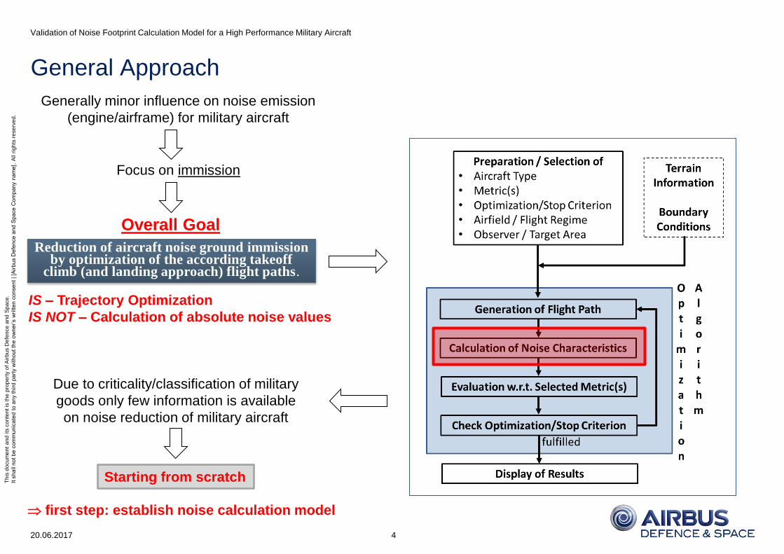
General Approach
20.06.2017
Validation of Noise Footprint Calculation Model for a High Performance Military Aircraft
4
Generally minor influence on noise emission
(engine/airframe) for military aircraft
Focus on immission
Reduction of aircraft noise ground immission by optimization of the according takeoff
climb (and landing approach) flight paths.
Overall Goal
Due to criticality/classification of military
goods only few information is available
on noise reduction of military aircraft
Starting from scratch
IS – Trajectory Optimization
IS NOT – Calculation of absolute noise values
first step: establish noise calculation model

Th
is d
ocu
me
nt
an
d its
co
nte
nt is
th
e p
rop
ert
y o
f A
irb
us D
efe
nce
an
d S
pa
ce
.
It s
ha
ll n
ot
be
co
mm
un
ica
ted
to
an
y t
hir
d p
art
y w
ith
ou
t th
e o
wn
er’
s w
ritt
en
co
nse
nt | [A
irb
us D
efe
nce
an
d S
pa
ce
Co
mp
an
y n
am
e].
All r
igh
ts r
ese
rve
d.
Outline of Noise Calculation Model
20.06.2017
Validation of Noise Footprint Calculation Model for a High Performance Military Aircraft
5
Transmission
Emission
Reflection
Immission S
Generic Modular
Approach
𝑳𝑷 = 𝑳𝑾 +𝑫+ 𝑨 (Metrics)
Th
is d
ocu
me
nt
an
d its
co
nte
nt is
th
e p
rop
ert
y o
f A
irb
us D
efe
nce
an
d S
pa
ce
.
It s
ha
ll n
ot
be
co
mm
un
ica
ted
to
an
y t
hir
d p
art
y w
ith
ou
t th
e o
wn
er’
s w
ritt
en
co
nse
nt | [A
irb
us D
efe
nce
an
d S
pa
ce
Co
mp
an
y n
am
e].
All r
igh
ts r
ese
rve
d.
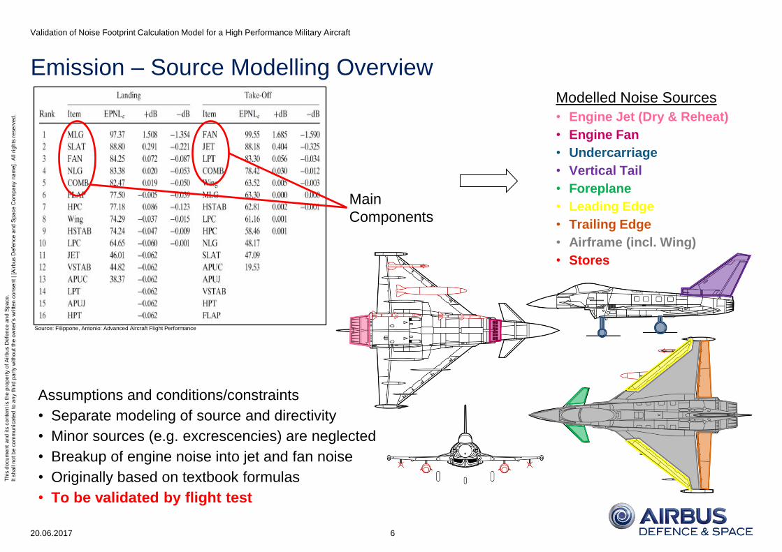
Emission – Source Modelling Overview
20.06.2017
Validation of Noise Footprint Calculation Model for a High Performance Military Aircraft
6
Modelled Noise Sources
• Engine Jet (Dry & Reheat)
• Engine Fan
• Undercarriage
• Vertical Tail
• Foreplane
• Leading Edge
• Trailing Edge
• Airframe (incl. Wing)
• Stores
Main
Components
Source: Filippone, Antonio: Advanced Aircraft Flight Performance
Assumptions and conditions/constraints
• Separate modeling of source and directivity
• Minor sources (e.g. excrescencies) are neglected
• Breakup of engine noise into jet and fan noise
• Originally based on textbook formulas
• To be validated by flight test

Th
is d
ocu
me
nt
an
d its
co
nte
nt is
th
e p
rop
ert
y o
f A
irb
us D
efe
nce
an
d S
pa
ce
.
It s
ha
ll n
ot
be
co
mm
un
ica
ted
to
an
y t
hir
d p
art
y w
ith
ou
t th
e o
wn
er’
s w
ritt
en
co
nse
nt | [A
irb
us D
efe
nce
an
d S
pa
ce
Co
mp
an
y n
am
e].
All r
igh
ts r
ese
rve
d.
Example: civil aircraft
Source: Bertsch, Eberhard-Lothar: Noise Prediction within Conceptual Aircraft Design
Emission – Directivity Characteristics (Near Field Behaviour)
20.06.2017
Validation of Noise Footprint Calculation Model for a High Performance Military Aircraft
7
Resulting modelling approach (engine components)
• 3-dim directivity correction
• No analytical solution possible/reasonable
• Derivation from noise measurements necessary
• Very expensive and time consuming process
• Cross-read (adapted civil a/c data) as interim solution
• To be validated/refined/corrected by flight test
NO homogenous expansion (at least for engine/fan)
Source: Bräunling, Willy: Flugzeugtriebwerke
Example: general engine noise emission characteristics
All other sources modelled as monopoles Uniform propagation (Directivity correction = 0)
Th
is d
ocu
me
nt
an
d its
co
nte
nt is
th
e p
rop
ert
y o
f A
irb
us D
efe
nce
an
d S
pa
ce
.
It s
ha
ll n
ot
be
co
mm
un
ica
ted
to
an
y t
hir
d p
art
y w
ith
ou
t th
e o
wn
er’
s w
ritt
en
co
nse
nt | [A
irb
us D
efe
nce
an
d S
pa
ce
Co
mp
an
y n
am
e].
All r
igh
ts r
ese
rve
d.
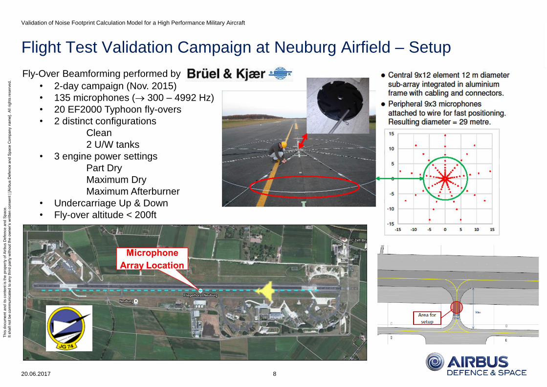
Flight Test Validation Campaign at Neuburg Airfield – Setup
20.06.2017
Validation of Noise Footprint Calculation Model for a High Performance Military Aircraft
8
Fly-Over Beamforming performed by
• 2-day campaign (Nov. 2015)
• 135 microphones ( 300 – 4992 Hz)
• 20 EF2000 Typhoon fly-overs
• 2 distinct configurations
Clean
2 U/W tanks
• 3 engine power settings
Part Dry
Maximum Dry
Maximum Afterburner
• Undercarriage Up & Down
• Fly-over altitude < 200ft
Th
is d
ocu
me
nt
an
d its
co
nte
nt is
th
e p
rop
ert
y o
f A
irb
us D
efe
nce
an
d S
pa
ce
.
It s
ha
ll n
ot
be
co
mm
un
ica
ted
to
an
y t
hir
d p
art
y w
ith
ou
t th
e o
wn
er’
s w
ritt
en
co
nse
nt | [A
irb
us D
efe
nce
an
d S
pa
ce
Co
mp
an
y n
am
e].
All r
igh
ts r
ese
rve
d.
Environmental Requirements for Beamforming
20.06.2017
Validation of Noise Footprint Calculation Model for a High Performance Military Aircraft
9
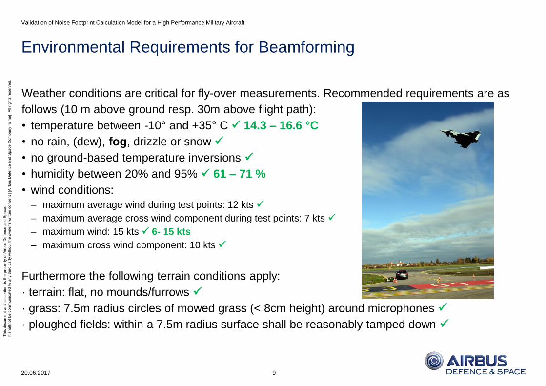
Weather conditions are critical for fly-over measurements. Recommended requirements are as
follows (10 m above ground resp. 30m above flight path):
• temperature between -10° and +35° C 14.3 – 16.6 °C
• no rain, (dew), fog, drizzle or snow
• no ground-based temperature inversions
• humidity between 20% and 95% 61 – 71 %
• wind conditions:
– maximum average wind during test points: 12 kts
– maximum average cross wind component during test points: 7 kts
– maximum wind: 15 kts 6- 15 kts
– maximum cross wind component: 10 kts
Furthermore the following terrain conditions apply:
· terrain: flat, no mounds/furrows
· grass: 7.5m radius circles of mowed grass (< 8cm height) around microphones
· ploughed fields: within a 7.5m radius surface shall be reasonably tamped down

Th
is d
ocu
me
nt
an
d its
co
nte
nt is
th
e p
rop
ert
y o
f A
irb
us D
efe
nce
an
d S
pa
ce
.
It s
ha
ll n
ot
be
co
mm
un
ica
ted
to
an
y t
hir
d p
art
y w
ith
ou
t th
e o
wn
er’
s w
ritt
en
co
nse
nt | [A
irb
us D
efe
nce
an
d S
pa
ce
Co
mp
an
y n
am
e].
All r
igh
ts r
ese
rve
d.
Flight Test Validation Campaign – Fly-overs
20.06.2017
Validation of Noise Footprint Calculation Model for a High Performance Military Aircraft
10

Th
is d
ocu
me
nt
an
d its
co
nte
nt is
th
e p
rop
ert
y o
f A
irb
us D
efe
nce
an
d S
pa
ce
.
It s
ha
ll n
ot
be
co
mm
un
ica
ted
to
an
y t
hir
d p
art
y w
ith
ou
t th
e o
wn
er’
s w
ritt
en
co
nse
nt | [A
irb
us D
efe
nce
an
d S
pa
ce
Co
mp
an
y n
am
e].
All r
igh
ts r
ese
rve
d.
Flight Test Validation Campaign - Beamforming
20.06.2017
Validation of Noise Footprint Calculation Model for a High Performance Military Aircraft
11
Meteo Data
Pass # Wind
Direction
[Deg]
Wind
Speed
[kts]
Temp.
[°C]
Humidity
[%]
1 280 10 16,6 71
2 290 7 16,6 71
3 300 7 16,6 71
4 290 6 16,6 71
9 270 8 16,7 70
SPL
FPR Pod
Flight Path
definition of
source areas
Emission Data
Sound Power
Validation of Noise Sources
Data processing/analysis and
Beamforming performed by
Immission Data
Sound Pressure
Sound Pressure Levels (measurements)
Validation of Overall System

Th
is d
ocu
me
nt
an
d its
co
nte
nt is
th
e p
rop
ert
y o
f A
irb
us D
efe
nce
an
d S
pa
ce
.
It s
ha
ll n
ot
be
co
mm
un
ica
ted
to
an
y t
hir
d p
art
y w
ith
ou
t th
e o
wn
er’
s w
ritt
en
co
nse
nt | [A
irb
us D
efe
nce
an
d S
pa
ce
Co
mp
an
y n
am
e].
All r
igh
ts r
ese
rve
d.
Flight Test Validation Campaign – Results Immission
20.06.2017
Validation of Noise Footprint Calculation Model for a High Performance Military Aircraft
12
Exemplary graph for one of a total of 9 branches
Original sound pressure sampling rate 16384Hz
Picture below shows 4Hz resolution (averaging)
Th
is d
ocu
me
nt
an
d its
co
nte
nt is
th
e p
rop
ert
y o
f A
irb
us D
efe
nce
an
d S
pa
ce
.
It s
ha
ll n
ot
be
co
mm
un
ica
ted
to
an
y t
hir
d p
art
y w
ith
ou
t th
e o
wn
er’
s w
ritt
en
co
nse
nt | [A
irb
us D
efe
nce
an
d S
pa
ce
Co
mp
an
y n
am
e].
All r
igh
ts r
ese
rve
d.
Flight Test Validation Campaign – Influence of Thrust Level on Noise
20.06.2017
Validation of Noise Footprint Calculation Model for a High Performance Military Aircraft
13
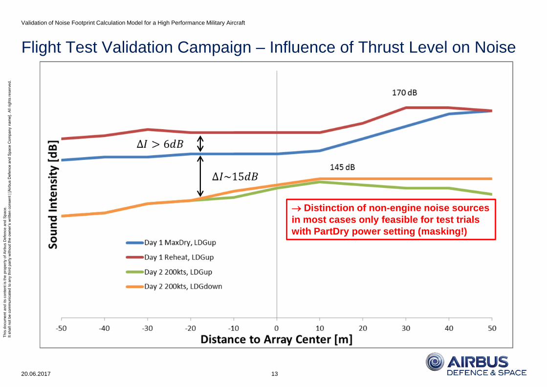
Distinction of non-engine noise sources
in most cases only feasible for test trials
with PartDry power setting (masking!)
Th
is d
ocu
me
nt
an
d its
co
nte
nt is
th
e p
rop
ert
y o
f A
irb
us D
efe
nce
an
d S
pa
ce
.
It s
ha
ll n
ot
be
co
mm
un
ica
ted
to
an
y t
hir
d p
art
y w
ith
ou
t th
e o
wn
er’
s w
ritt
en
co
nse
nt | [A
irb
us D
efe
nce
an
d S
pa
ce
Co
mp
an
y n
am
e].
All r
igh
ts r
ese
rve
d.
Flight Test Validation Campaign – Results Emission
20.06.2017
Validation of Noise Footprint Calculation Model for a High Performance Military Aircraft
14
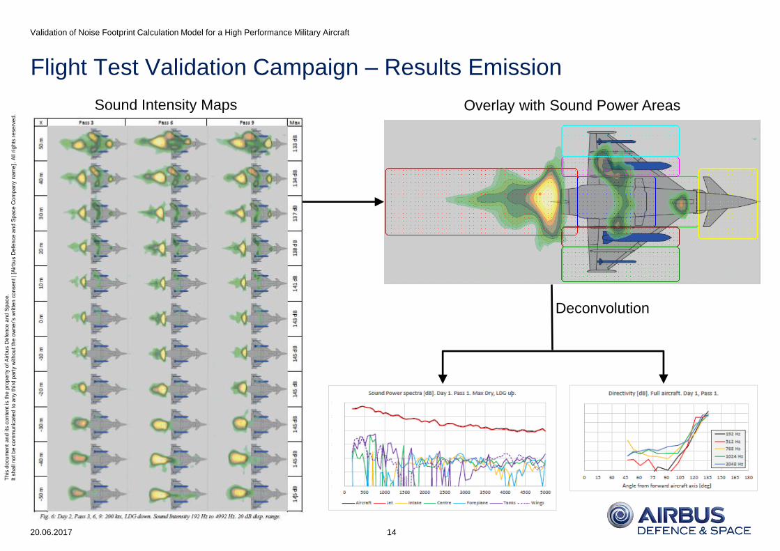
Sound Intensity Maps Overlay with Sound Power Areas
Deconvolution

Th
is d
ocu
me
nt
an
d its
co
nte
nt is
th
e p
rop
ert
y o
f A
irb
us D
efe
nce
an
d S
pa
ce
.
It s
ha
ll n
ot
be
co
mm
un
ica
ted
to
an
y t
hir
d p
art
y w
ith
ou
t th
e o
wn
er’
s w
ritt
en
co
nse
nt | [A
irb
us D
efe
nce
an
d S
pa
ce
Co
mp
an
y n
am
e].
All r
igh
ts r
ese
rve
d.
Noise Model Validation – General Approach
20.06.2017
Validation of Noise Footprint Calculation Model for a High Performance Military Aircraft
15
Flight trials
at Neuburg
Textbook
approaches
Flight trials
by WTD91
Manufacturer
material
Flight trials
by BAeS
Flight trials
armasuisse
Overall system V
a
l
i
d
a
t
i
o
n
E
v
i
d
e
n
c
e
V
a
l
i
d
a
t
i
o
n
E
v
i
d
e
n
c
e
Preliminary Model
Matching
Matching
Y
Adaption of
Model Parameters
N
Validated
Model
Engine Components
Source and Directivity modelled
Non-Engine Components
Modelling as monopole
• Uniform propagation (D=0)
• Only sources modelled
Y
N
Adaption of Model
Preliminary Model
Matching
Matching
Adaption of
Model Parameters
N
Y
Validated
Model
Y
Adaption of Model
Def. of Directivities
N

Th
is d
ocu
me
nt
an
d its
co
nte
nt is
th
e p
rop
ert
y o
f A
irb
us D
efe
nce
an
d S
pa
ce
.
It s
ha
ll n
ot
be
co
mm
un
ica
ted
to
an
y t
hir
d p
art
y w
ith
ou
t th
e o
wn
er’
s w
ritt
en
co
nse
nt | [A
irb
us D
efe
nce
an
d S
pa
ce
Co
mp
an
y n
am
e].
All r
igh
ts r
ese
rve
d.
Emission – Modelling of Engine Combustion Noise
20.06.2017
Validation of Noise Footprint Calculation Model for a High Performance Military Aircraft
16
Exit NozzleAfterburner
Low Pressure Turbine
High Pressure TurbineCombustion Chamber
CompressorCompressor
Bypass
Source: http://eurofighter.airpower.at
Combustion Sound Power
4
0
2
0
,
2
,
,,210
T
T
p
p
T
TTmaP TurbinComb
inComb
inComboutCombC
Combe
with exponent Ce: engine specific constant, a: speed of sound, 𝑚 : mass flow,
Tcomb,in/out: combustion chamber in/outlet temperature, pComb,in: combustion
chamber inlet pressure, Tturb: temperature increase in turbine
Combustion Sound Power Level
0
, log10P
PL Comb
CombW
Flight Test Corrections
Analysis of flight test data (see figure below) showed
Combustion noise hardly measurably separately
Combustion contribution to jet noise negligible
Combustion covered by overall jet noise model
Unified re-modelling of jet noise necessary
see jet noise modelling slides
Th
is d
ocu
me
nt
an
d its
co
nte
nt is
th
e p
rop
ert
y o
f A
irb
us D
efe
nce
an
d S
pa
ce
.
It s
ha
ll n
ot
be
co
mm
un
ica
ted
to
an
y t
hir
d p
art
y w
ith
ou
t th
e o
wn
er’
s w
ritt
en
co
nse
nt | [A
irb
us D
efe
nce
an
d S
pa
ce
Co
mp
an
y n
am
e].
All r
igh
ts r
ese
rve
d.
Emission – Details of Re-Modelling of Engine Jet Noise
20.06.2017
Validation of Noise Footprint Calculation Model for a High Performance Military Aircraft
17
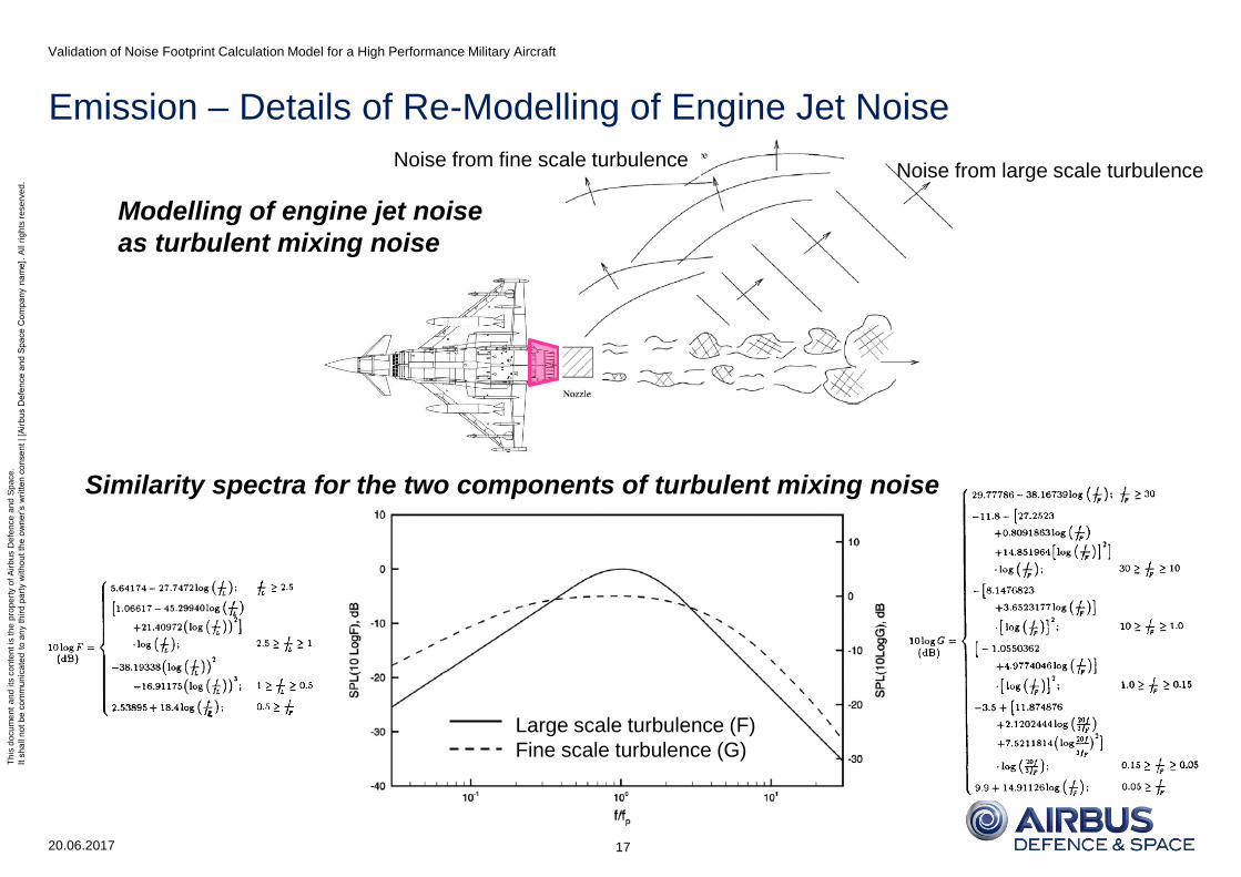
Noise from large scale turbulence Noise from fine scale turbulence
Similarity spectra for the two components of turbulent mixing noise
Large scale turbulence (F)
Fine scale turbulence (G)
Modelling of engine jet noise
as turbulent mixing noise

Th
is d
ocu
me
nt
an
d its
co
nte
nt is
th
e p
rop
ert
y o
f A
irb
us D
efe
nce
an
d S
pa
ce
.
It s
ha
ll n
ot
be
co
mm
un
ica
ted
to
an
y t
hir
d p
art
y w
ith
ou
t th
e o
wn
er’
s w
ritt
en
co
nse
nt | [A
irb
us D
efe
nce
an
d S
pa
ce
Co
mp
an
y n
am
e].
All r
igh
ts r
ese
rve
d.
Emission – Directivity for Engine Jet Noise (FlightIdle - MaxDry)
20.06.2017
Validation of Noise Footprint Calculation Model for a High Performance Military Aircraft
18
Realistically to be determined empirically by respective flight tests
Directivity characteristics for Combustion included
Current approach based on reference model
Measurement of free stream characteristics
Adapted to actual case (military aircraft engine)
Taken from textbook – only rough approximation
Flight Test Corrections
Emission
Angle [°]
Directivity
Corr. [dB]
0
60
90
100
110
120
130
140
150
160
170
180
Offset model-FT between ~90°-130° emission angle
Re-modelling (additional dependency on thrust lever)

Th
is d
ocu
me
nt
an
d its
co
nte
nt is
th
e p
rop
ert
y o
f A
irb
us D
efe
nce
an
d S
pa
ce
.
It s
ha
ll n
ot
be
co
mm
un
ica
ted
to
an
y t
hir
d p
art
y w
ith
ou
t th
e o
wn
er’
s w
ritt
en
co
nse
nt | [A
irb
us D
efe
nce
an
d S
pa
ce
Co
mp
an
y n
am
e].
All r
igh
ts r
ese
rve
d.
Emission – Modelling of Undercarriage Noise
20.06.2017
Validation of Noise Footprint Calculation Model for a High Performance Military Aircraft
19
Assumption: monopole model uniform propagation Directivity correction D = 0
Flight Test Corrections
Landing Gear Sound Pressure
)(2 fFr
AMaqp
ref
LG
withq: dynamic pressure, Ma: free stream Mach number,
A: equivalent landing gear surface area, rref: reference length
: empirical reference amplitude for frequency spectrum,
and the frequency (f) correction function using Strouhal number St
Landing Gear Sound Pressure Level
0
, log20p
pL LG
LGp
q
StStq
StStqfF
0
0
1/
V
lffStSt
ref
with lref: reference length, V: free stream velocity
,,q: empirical parameters
Parameter adaptation: , , St0
rod system
tyre
attachment
parts
Th
is d
ocu
me
nt
an
d its
co
nte
nt is
th
e p
rop
ert
y o
f A
irb
us D
efe
nce
an
d S
pa
ce
.
It s
ha
ll n
ot
be
co
mm
un
ica
ted
to
an
y t
hir
d p
art
y w
ith
ou
t th
e o
wn
er’
s w
ritt
en
co
nse
nt | [A
irb
us D
efe
nce
an
d S
pa
ce
Co
mp
an
y n
am
e].
All r
igh
ts r
ese
rve
d.
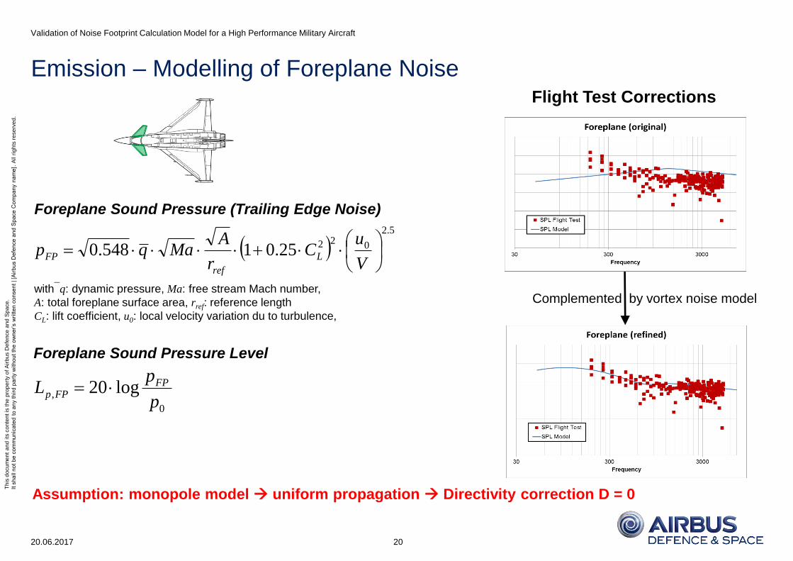
Emission – Modelling of Foreplane Noise
20.06.2017
Validation of Noise Footprint Calculation Model for a High Performance Military Aircraft
20
Assumption: monopole model uniform propagation Directivity correction D = 0
Foreplane Sound Pressure (Trailing Edge Noise)
Flight Test Corrections
5.2
02225.01548.0
V
uC
r
AMaqp L
ref
FP
withq: dynamic pressure, Ma: free stream Mach number,
A: total foreplane surface area, rref: reference length
CL: lift coefficient, u0: local velocity variation du to turbulence,
Foreplane Sound Pressure Level
0
, log20p
pL FP
FPp
Complemented by vortex noise model

Th
is d
ocu
me
nt
an
d its
co
nte
nt is
th
e p
rop
ert
y o
f A
irb
us D
efe
nce
an
d S
pa
ce
.
It s
ha
ll n
ot
be
co
mm
un
ica
ted
to
an
y t
hir
d p
art
y w
ith
ou
t th
e o
wn
er’
s w
ritt
en
co
nse
nt | [A
irb
us D
efe
nce
an
d S
pa
ce
Co
mp
an
y n
am
e].
All r
igh
ts r
ese
rve
d.
Emission – Modelling of Trailing Edge Noise
20.06.2017
Validation of Noise Footprint Calculation Model for a High Performance Military Aircraft
21
Assumption: monopole model uniform propagation Directivity correction D = 0
Flight Test Corrections
Trailing Edge Sound Pressure
5.2
02225.01548.0
V
uC
r
AMaqp L
ref
TE
withq: dynamic pressure, Ma: free stream Mach number,
A: total trailing edge surface area, rref: reference length
CL: lift coefficient, u0: local velocity variation du to turbulence,
Trailing Edge Sound Pressure Level
0
, log20p
pL TE
TEp
No isolated noise signal for trailing edge extractable
Actual sound power model seems resonable (see below)
Read-across of spectral form from foreplane feasible
including vortex noise model complement

Th
is d
ocu
me
nt
an
d its
co
nte
nt is
th
e p
rop
ert
y o
f A
irb
us D
efe
nce
an
d S
pa
ce
.
It s
ha
ll n
ot
be
co
mm
un
ica
ted
to
an
y t
hir
d p
art
y w
ith
ou
t th
e o
wn
er’
s w
ritt
en
co
nse
nt | [A
irb
us D
efe
nce
an
d S
pa
ce
Co
mp
an
y n
am
e].
All r
igh
ts r
ese
rve
d.
Emission – Modelling of Leading Edge Noise
20.06.2017
Validation of Noise Footprint Calculation Model for a High Performance Military Aircraft
22
Assumption: monopole model uniform propagation Directivity correction D = 0
Flight Test Corrections
Normalized LE Sound Pressure Level from WTT TELEnormp StL 225.0)log(35.93,
withcLE: average LE chord, LE: slat deflection, TE: flap deflection
geopVpnormpLEp LLLL ,,,,
refle
le
ref
VpV
VL
,
,cos
coslog30log50
with sLE: span slat, LE: leading edge sweep
• LE de facto a dipole showing distinctive directivity
• Currently no WT / FT data for military aircraft available
• Simplification of directivity feasible for T/O, not for landing
• To be refined in a later stage of model development
• Semiempirical approach
• Based on wind tunnel tests for commercial aircraft
• Adapted to high performance military aircraft
Leading Edge Sound Pressure Level
)log(181.115, StL normp
sStSt
sStSt
21
225.06.21
10TELE
sSt
V
cfSt LE
2,cos
log100.5refLE
LELEgeop
r
scL
Velocity (Lp,V) and geometric (Lp,geo) correction
Flight Test data prove unrealistic LE modelling
LE noise contribution is modelled much too high
Not enough FT data for realistic re-modelling
LE retracted: noise masked by other sources
LE extended: no measurements ( neglected)
Incorporation of LE noise into surface noise feasible
Increment on roughness height in surface noise

Th
is d
ocu
me
nt
an
d its
co
nte
nt is
th
e p
rop
ert
y o
f A
irb
us D
efe
nce
an
d S
pa
ce
.
It s
ha
ll n
ot
be
co
mm
un
ica
ted
to
an
y t
hir
d p
art
y w
ith
ou
t th
e o
wn
er’
s w
ritt
en
co
nse
nt | [A
irb
us D
efe
nce
an
d S
pa
ce
Co
mp
an
y n
am
e].
All r
igh
ts r
ese
rve
d.
Emission – Modelling of Vertical Tail Noise
20.06.2017
Validation of Noise Footprint Calculation Model for a High Performance Military Aircraft
23
Assumption: monopole model uniform propagation Directivity correction D = 0
Flight Test Corrections
Vertical Tail Sound Pressure (Trailing Edge Noise)
Currently no correctio/refinement/validation
No according flight test data available
Effect negligible due to minor relevance
No significant contribution to overall noise
5.2
02225.01548.0
V
uC
r
AMaqp L
ref
Fin
withq: dynamic pressure, Ma: free stream Mach number,
A: total vertical tail surface area, rref: reference length
CL: lift coefficient, u0: local velocity variation du to turbulence,
Vertical Tail Sound Pressure Level
0
, log20p
pL Fin
Finp
Surface noise component / contribution neglected!
Th
is d
ocu
me
nt
an
d its
co
nte
nt is
th
e p
rop
ert
y o
f A
irb
us D
efe
nce
an
d S
pa
ce
.
It s
ha
ll n
ot
be
co
mm
un
ica
ted
to
an
y t
hir
d p
art
y w
ith
ou
t th
e o
wn
er’
s w
ritt
en
co
nse
nt | [A
irb
us D
efe
nce
an
d S
pa
ce
Co
mp
an
y n
am
e].
All r
igh
ts r
ese
rve
d.
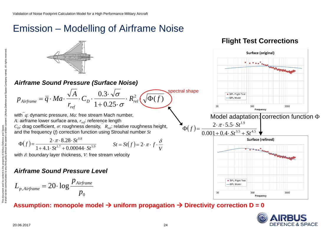
Emission – Modelling of Airframe Noise
20.06.2017
Validation of Noise Footprint Calculation Model for a High Performance Military Aircraft
24
Assumption: monopole model uniform propagation Directivity correction D = 0
Airframe Sound Pressure (Surface Noise)
)(25.01
3.0 2 fRCr
AMaqp relD
ref
Airframe
withq: dynamic pressure, Ma: free stream Mach number,
A: airframe lower surface area, rref: reference length
CD: drag coefficient, : roughness density, Rrel: relative roughness height,
and the frequency (f) correction function using Strouhal number St
Airframe Sound Pressure Level
0
, log20p
pL
Airframe
Airframep
9.57.1
8.0
00044.01.41
28.82
StSt
Stf
VffStSt
2
with : boundary layer thickness, V: free stream velocity
Flight Test Corrections
Model adaptation: correction function
5.45.3
9.1
4.0001.0
5.52
StSt
Stf
spectral shape
Th
is d
ocu
me
nt
an
d its
co
nte
nt is
th
e p
rop
ert
y o
f A
irb
us D
efe
nce
an
d S
pa
ce
.
It s
ha
ll n
ot
be
co
mm
un
ica
ted
to
an
y t
hir
d p
art
y w
ith
ou
t th
e o
wn
er’
s w
ritt
en
co
nse
nt | [A
irb
us D
efe
nce
an
d S
pa
ce
Co
mp
an
y n
am
e].
All r
igh
ts r
ese
rve
d.
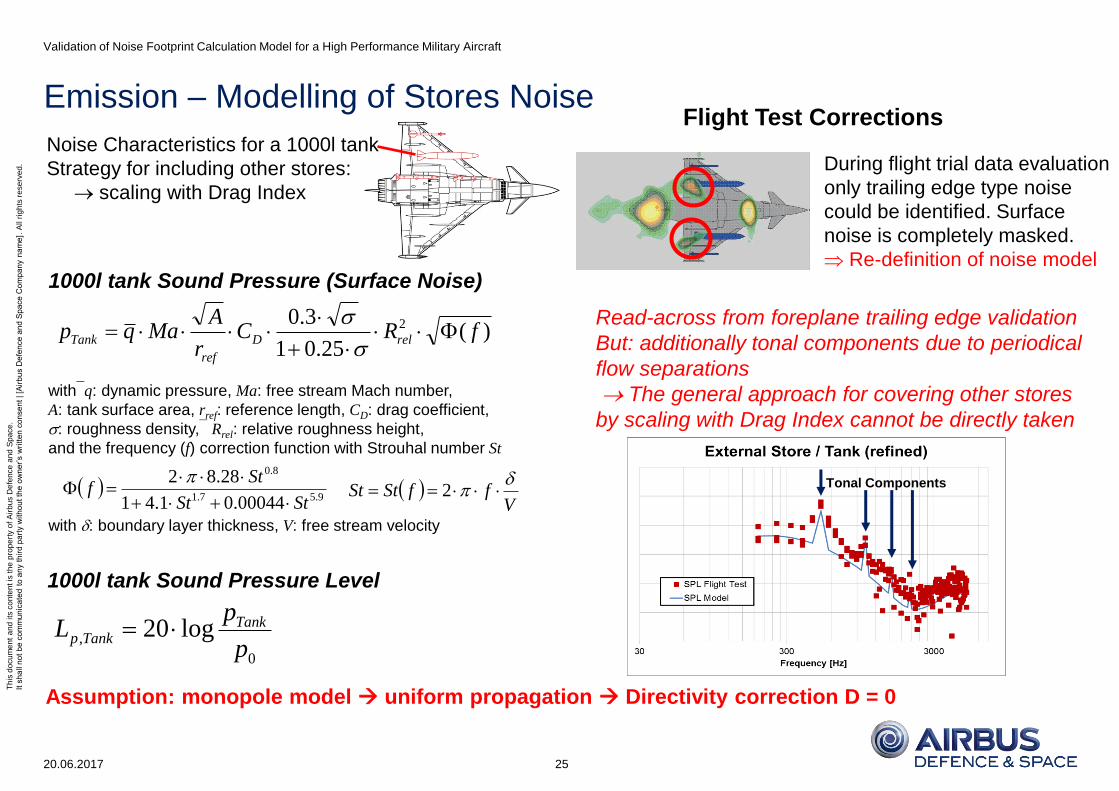
Emission – Modelling of Stores Noise
20.06.2017
Validation of Noise Footprint Calculation Model for a High Performance Military Aircraft
25
Assumption: monopole model uniform propagation Directivity correction D = 0
Flight Test Corrections Noise Characteristics for a 1000l tank
Strategy for including other stores:
scaling with Drag Index
1000l tank Sound Pressure (Surface Noise)
)(25.01
3.0 2 fRCr
AMaqp relD
ref
Tank
withq: dynamic pressure, Ma: free stream Mach number,
A: tank surface area, rref: reference length, CD: drag coefficient,
: roughness density, Rrel: relative roughness height,
and the frequency (f) correction function with Strouhal number St
1000l tank Sound Pressure Level
0
, log20p
pL Tank
Tankp
9.57.1
8.0
00044.01.41
28.82
StSt
Stf
VffStSt
2
with : boundary layer thickness, V: free stream velocity
During flight trial data evaluation
only trailing edge type noise
could be identified. Surface
noise is completely masked.
Re-definition of noise model
Read-across from foreplane trailing edge validation
But: additionally tonal components due to periodical
flow separations
The general approach for covering other stores
by scaling with Drag Index cannot be directly taken
Tonal Components
Th
is d
ocu
me
nt
an
d its
co
nte
nt is
th
e p
rop
ert
y o
f A
irb
us D
efe
nce
an
d S
pa
ce
.
It s
ha
ll n
ot
be
co
mm
un
ica
ted
to
an
y t
hir
d p
art
y w
ith
ou
t th
e o
wn
er’
s w
ritt
en
co
nse
nt | [A
irb
us D
efe
nce
an
d S
pa
ce
Co
mp
an
y n
am
e].
All r
igh
ts r
ese
rve
d.
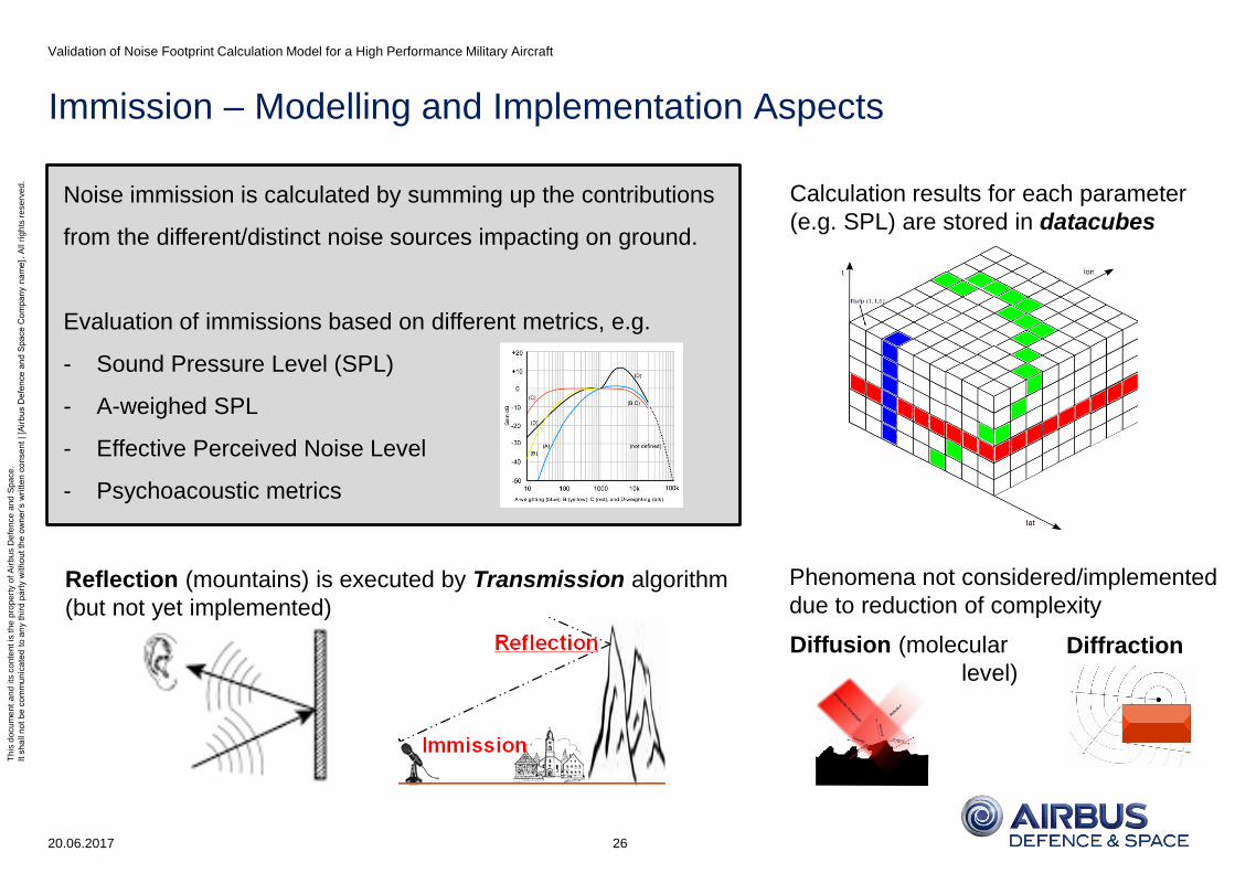
Immission – Modelling and Implementation Aspects
20.06.2017
Validation of Noise Footprint Calculation Model for a High Performance Military Aircraft
26
Reflection (mountains) is executed by Transmission algorithm
(but not yet implemented)
Noise immission is calculated by summing up the contributions
from the different/distinct noise sources impacting on ground.
Evaluation of immissions based on different metrics, e.g.
- Sound Pressure Level (SPL)
- A-weighed SPL
- Effective Perceived Noise Level
- Psychoacoustic metrics
Phenomena not considered/implemented
due to reduction of complexity
Diffraction Diffusion (molecular
level)
Calculation results for each parameter
(e.g. SPL) are stored in datacubes

Th
is d
ocu
me
nt
an
d its
co
nte
nt is
th
e p
rop
ert
y o
f A
irb
us D
efe
nce
an
d S
pa
ce
.
It s
ha
ll n
ot
be
co
mm
un
ica
ted
to
an
y t
hir
d p
art
y w
ith
ou
t th
e o
wn
er’
s w
ritt
en
co
nse
nt | [A
irb
us D
efe
nce
an
d S
pa
ce
Co
mp
an
y n
am
e].
All r
igh
ts r
ese
rve
d.
Immission – Graphical Representation of Noise Footprints
20.06.2017
Validation of Noise Footprint Calculation Model for a High Performance Military Aircraft
27
Based on Matlab using Google Maps Api Functions
WGS (World Geodetic System) 84 Coordinates
Terrain Representation potentially based on NASA SRTM
currently checked (resolution ~30m)
interface yet provided

Th
is d
ocu
me
nt
an
d its
co
nte
nt is
th
e p
rop
ert
y o
f A
irb
us D
efe
nce
an
d S
pa
ce
.
It s
ha
ll n
ot
be
co
mm
un
ica
ted
to
an
y t
hir
d p
art
y w
ith
ou
t th
e o
wn
er’
s w
ritt
en
co
nse
nt | [A
irb
us D
efe
nce
an
d S
pa
ce
Co
mp
an
y n
am
e].
All r
igh
ts r
ese
rve
d.
Transmission – Modelling of Noise Propagation
20.06.2017
Validation of Noise Footprint Calculation Model for a High Performance Military Aircraft
28
Reference Point
d0 distance
Time t0 Original approach: timmission = temission
• Noise emission @t0 immission @t0
• Noise emission @t0+125ms immission @t0+125ms
Improved approach:
Simplified (linearised) Ray Tracing
Modelled noise “loss” by absorption (ISO 9613-1)
• Geometric (depending on distance from source)
• Atmospheric (molecular absorption)
• Soil damping (for small immission angles)
Doppler Effect included
Noise reflection not yet modelled, but planned for
Wind & temperature effects (refraction) neglected
d1
But obviously more realistically (a = speed of sound)
• Noise emission @t0 immission @t0+d0/a
• Noise emission @t0+125ms immission @t0+125ms+d1/a
Inconsistencies due to discretisation
t0+125ms+d1/a
t0+250ms+d2/a
t0+375ms+d3/a
Th
is d
ocu
me
nt
an
d its
co
nte
nt is
th
e p
rop
ert
y o
f A
irb
us D
efe
nce
an
d S
pa
ce
.
It s
ha
ll n
ot
be
co
mm
un
ica
ted
to
an
y t
hir
d p
art
y w
ith
ou
t th
e o
wn
er’
s w
ritt
en
co
nse
nt | [A
irb
us D
efe
nce
an
d S
pa
ce
Co
mp
an
y n
am
e].
All r
igh
ts r
ese
rve
d.
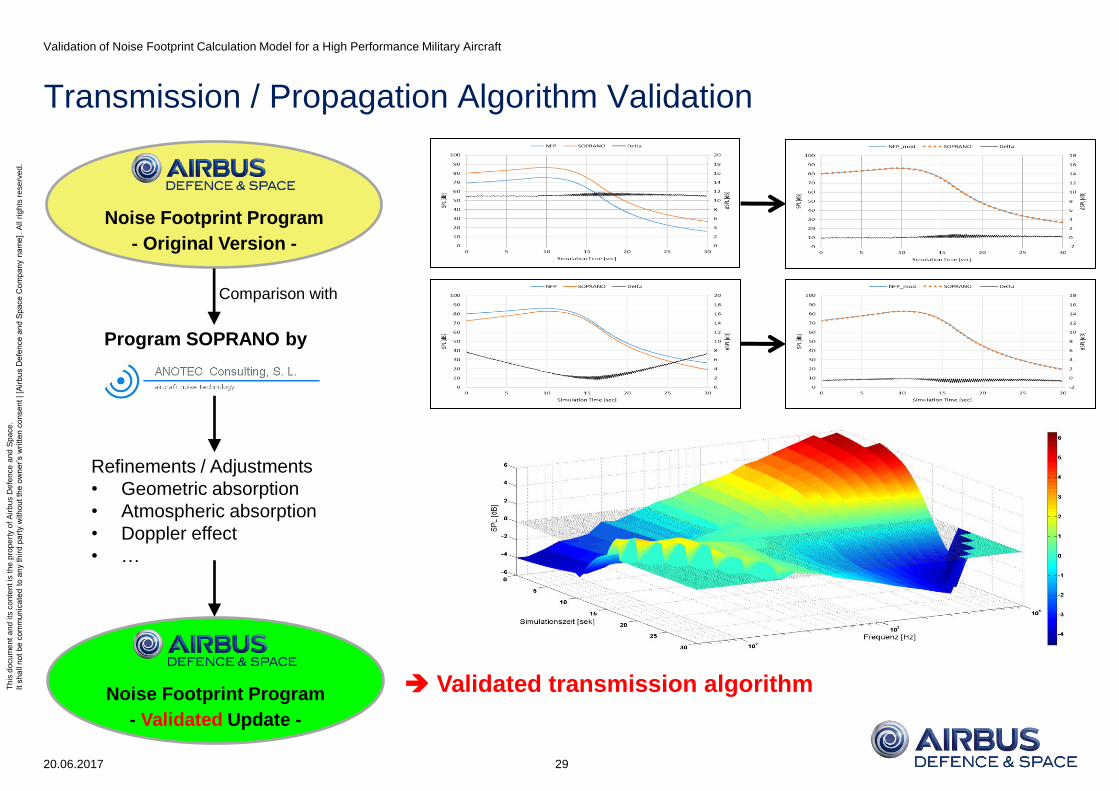
Transmission / Propagation Algorithm Validation
20.06.2017
Validation of Noise Footprint Calculation Model for a High Performance Military Aircraft
29
Validated transmission algorithm
Comparison with
Refinements / Adjustments
• Geometric absorption
• Atmospheric absorption
• Doppler effect
• …
Noise Footprint Program
- Original Version -
Program SOPRANO by
Noise Footprint Program
- Validated Update -

Th
is d
ocu
me
nt
an
d its
co
nte
nt is
th
e p
rop
ert
y o
f A
irb
us D
efe
nce
an
d S
pa
ce
.
It s
ha
ll n
ot
be
co
mm
un
ica
ted
to
an
y t
hir
d p
art
y w
ith
ou
t th
e o
wn
er’
s w
ritt
en
co
nse
nt | [A
irb
us D
efe
nce
an
d S
pa
ce
Co
mp
an
y n
am
e].
All r
igh
ts r
ese
rve
d.
Transmission / Propagation Algorithm Validation - Results
20.06.2017
Validation of Noise Footprint Calculation Model for a High Performance Military Aircraft
30
Example: noise footprint of a turning flight 15 secs after takeoff
Original implementation Refined algorithm
Th
is d
ocu
me
nt
an
d its
co
nte
nt is
th
e p
rop
ert
y o
f A
irb
us D
efe
nce
an
d S
pa
ce
.
It s
ha
ll n
ot
be
co
mm
un
ica
ted
to
an
y t
hir
d p
art
y w
ith
ou
t th
e o
wn
er’
s w
ritt
en
co
nse
nt | [A
irb
us D
efe
nce
an
d S
pa
ce
Co
mp
an
y n
am
e].
All r
igh
ts r
ese
rve
d.
Summary
Resuming the introductory questions
• Why do we (have to) put focus on military aircraft noise?
Increasing public pressure / flight regulations / customer requirements
• Where did we start from?
Starting from scratch
• What is our overall approach?
Noise reduction by flight path optimisation
Strictly modular analytical modelling approach to be validated by flight test
• Where do we stand today?
Simplified (flying) aircraft noise model almost completely validated
• What are our main results (up to now)?
First calculations look promising
... and one more question …
20.06.2017
Validation of Noise Footprint Calculation Model for a High Performance Military Aircraft
31
Th
is d
ocu
me
nt
an
d its
co
nte
nt is
th
e p
rop
ert
y o
f A
irb
us D
efe
nce
an
d S
pa
ce
.
It s
ha
ll n
ot
be
co
mm
un
ica
ted
to
an
y t
hir
d p
art
y w
ith
ou
t th
e o
wn
er’
s w
ritt
en
co
nse
nt | [A
irb
us D
efe
nce
an
d S
pa
ce
Co
mp
an
y n
am
e].
All r
igh
ts r
ese
rve
d.
Outlook
How do we plan to proceed?
• Final refinements of emission model including directivity characteristics
• Complete validation of the noise model based on flight test noise measurements
• Revision / additional investigation on feasibility of monopole assumption for landing gear
• Integration of wind and temperature effects into transmission algorithm
• Parallelization
• Integration of a terrain data base into the model
• Integration of a terrain data base into the graphical noise footprint representation
• Comfortable graphics based user interface for noise calculation model
• Embedding of the noise calculation model into an flight path optimisation algorithm
… and many more
20.06.2017
Validation of Noise Footprint Calculation Model for a High Performance Military Aircraft
32
Current work in progress …

Th
is d
ocu
me
nt
an
d its
co
nte
nt is
th
e p
rop
ert
y o
f A
irb
us D
efe
nce
an
d S
pa
ce
.
It s
ha
ll n
ot
be
co
mm
un
ica
ted
to
an
y t
hir
d p
art
y w
ith
ou
t th
e o
wn
er’
s w
ritt
en
co
nse
nt | [A
irb
us D
efe
nce
an
d S
pa
ce
Co
mp
an
y n
am
e].
All r
igh
ts r
ese
rve
d.
Th
is d
ocu
me
nt
an
d its
co
nte
nt is
th
e p
rop
ert
y o
f A
irb
us D
efe
nce
an
d S
pa
ce
.
It s
ha
ll n
ot
be
co
mm
un
ica
ted
to
an
y t
hir
d p
art
y w
ith
ou
t th
e o
wn
er’
s w
ritt
en
co
nse
nt | [A
irb
us D
efe
nce
an
d S
pa
ce
Co
mp
an
y n
am
e].
All r
igh
ts r
ese
rve
d.
Thank you for your attention!
Any questions?
20.06.2017 33
Validation of Noise Footprint Calculation Model for a High Performance Military Aircraft