nokia data modems os 2810 300 bit/s data...
TRANSCRIPT
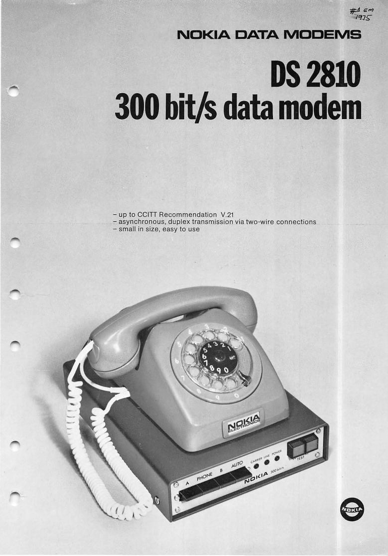
NOKIA DATA MODEMS
OS 2810 300 bit/s data modem
- up to CCITI Recommendation V.21 - asynchronous, duplex transmission via two-wire connections - small in size, easy to use
e
Small and handy, easy to use The Nokia DS 2810 300 bit/s data modem is very small: 5.5cmhigh.20cmwide.30cmdeep. lt can be placed, say, under a normal telephone seI.
The modem itself includes ali the switches and indicators for operation, so separate control units are unnecessary. The modem can also be controlled by any data terminal.
Inslallation and maintenance are extremely easy: just remove lhe botlom plate to change the mains cable, fuse, etc.
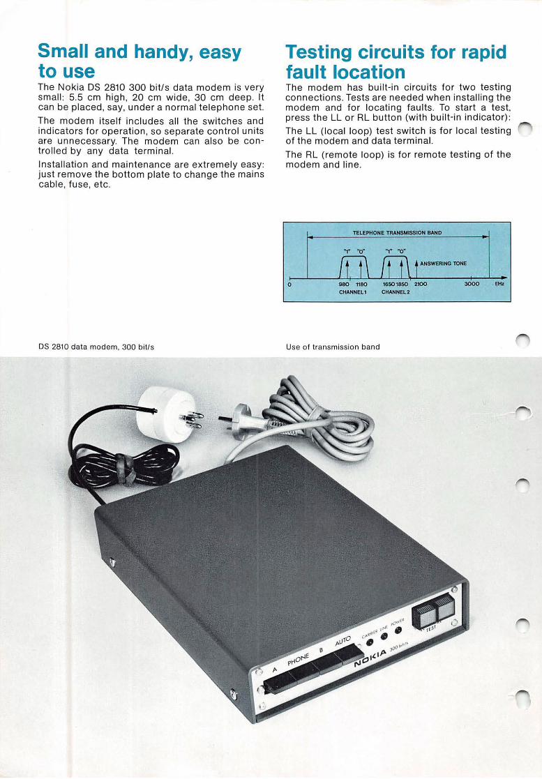
DS 2810 data modem, 300 bit!s
Testing circuits for rapid fault location The modem has built-in circuits for two testing connections. Tests are needed when installing the modem and for locating faults . To start a te sI. press the LL or RL butlon (with built-in indicator):
The LL (local loop) test switch is for local testing Df the modem and data terminal.
The RL (remote loop) is for remote testing of the modem and line.
TElEPHONE TRANSMISSION BANO
ANSWERING TONE
o 980 1180 1850 1850 2100 3000 f/tu CHANNEll CHANNEL2
Use of transmission band
Principie of operation
Bolh lhe modulalor and lhe demodulalor are digi la l and are conlroll ed by cryslal oscillalors. lhis makes .lheir operalion exlremely slable and reliable.
Transmitter lhe modulalor incorporales a digilal square-wave generalor. Ils oulpul frequency depends on lhe dala lo be Iransmitted and on lhe channel in use. lo avoid cross-ta lk, the spectrum of the square wave is limited lo a band of 300 Hz.
Receiver lhe received signal goes Ihrough a hybrid Iransformer and channel filler l o lhe demodulalor and line-signal detector. lhe line-signal delector checks thal the levei of the received signal is sufficient for demodulalion .
After the channel filler, lhe signal is amplified and connected l o a digilal frequency discriminalor. II is Ihen low-pass filtered. lhe received dala are obtained via a slicer and an inlerface ampl ifier.
Automatic answering
Automalic answering complies wilh CCITI Recommendation V.25. lhe ringing current is detected by a relay and lhe modem gives lhe data terminal a check signal. lhe modem connects itself to lhe line and Iransmils an answerings tone of 2100 Hz for 3.5 seconds. lhe conneclion is Ihen ready for dala Iransmission.
lhe conneclion is normally swilched off aI lhe dala lerminal. If necessary, il can also be swilched of! aulomatically by lhe modem or manually. If aulomalic, lhe conneclion is swilched of! after the carrier detector has been in the of! posilion for a tota l of 30 seconds (nol necessary conlinuously) .
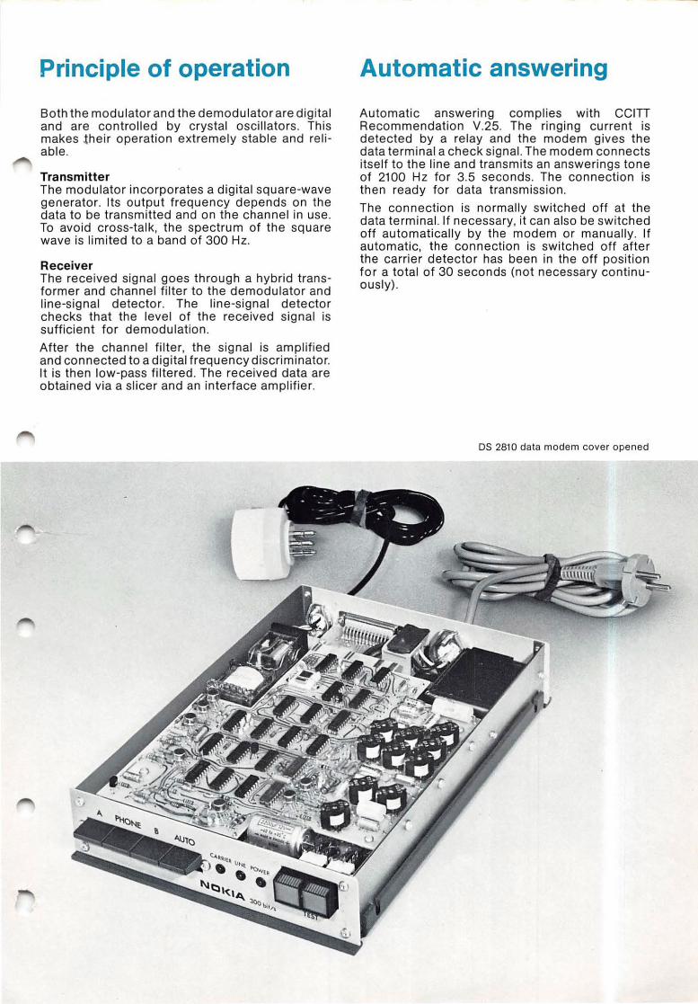
OS 2810 data modem cover opened

Technical data
Transmission rate
Terminal connection
Input vo ltage Input impedance Output vo ltage Output impedance
Connection to line Impedance Return loss at 300 ... 3400 Hz Common mode rejectio n at 300 ... 3400 Hz DC loop res istance Max. permissib le DC loop current
Output leve i Inpu t levei
0 .. 300 bit/s
according to CCITT Recommendations V.24 and V.28 +3 ... +25 V, -3 ... -25 V 4.5 ... 5 kohm +8 ... +12 V, -8 ... -12 V approx. 300 ohm
600 ohm
15 dB or betler
50 dB or better 100 ohm or less
120 mA
0 ... -15 dBm 0 ... -43 dBm
Ringing detector sens iti vity at 25 Hz
at 50 Hz
Mains connection Voltage
Power consumption
Environment Temperature Relative humidity
Dimensions Width Depth Height
20 V rm s, 5 mA. or less 20 V rm s, 5 mA, or less
220 V+ 10%/-15%, 50 ... 60 Hz 10 VA
0 ... +400 C 75%lor70% 01 operating time 95 % lor 30 % 01 operating time
205 mm 299 mm
55mm
Ringing detector impedance at 25 Hz
at 50 Hz 5 kohm or more 3.5 kohm or more
Our policy is one of continuous development and improvement. We reserve the right to aUer technical details without notice.
'0' Rpody lar spnding
'0' Trn"mill.d doIa , RrclâvHi tine
, 5'gnol detector
Terminal cOflnr-c/or :~w:3::::::::~::~I'~~~rrii~~~~jic;:f~~::~~!::j~~~:;: /26 104
101 Se/ r cl >--R"'.o,,,~;v~ do ia 103 channel 56 S5
:~ 1"1 106
:&$ Te5fRL.../",LJ-+_I+_+-l--4 109 .r-'
125 ~S~'---~-tt--l---t~í=J:::~--n
J---"
W' /25
PH~
f/' A~
CHANNEL,
AHSWERING
'----4+-----1 TON E ~r===~:;~~~:J-'"""J~---{]:~ CA L N-AND NECTOR
53 '08
Conned dalo sei lo line /Da lo terminal r~dy 5ignol _ 102 ~ grQund Im SI
Pro/rdi ve i " l ground or ror/h ..,.
220V...,":::::::~~t:
UNE RELAyI+R!!!i"n'--__________ --=.i~ ________ +--,~ CONTROL Lme ,elo
e3 ~8V I t.OOmA ~ . 11V
E3 ~_ 'lV I ' OO mA ~
E3 ~.sv I '.6A ~1..POWER
e Oy Nokia Ab Electron ics, Telecommunication systems P.O.Box 780, SF-00101 HELSINKI10, Fin land Telephone: Interna ti o na I + 358 O 59131 and + 358 O 5671. National (90) 59131 and (90) 5671 Telex 12 2062 and 12 579 eleno 51 Telegrams ELECTRONOKIA
Line
'25 Ca ll ing indico tor
OS 2810 block diagram
M2S10 El 261 Printed in Finland by Painomestarit Oy 1977