non-contact radar level monitoring transmitter · nrm /-2020 1 measuring • monitoring •...
TRANSCRIPT
NRM
1/03
- 20
20
1
N2
measuring
•
monitoring
•
analysing
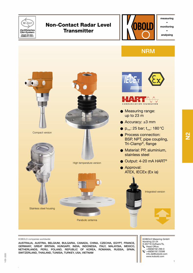
Non-Contact Radar Level Transmitter
KOBOLD Messring GmbHNordring 22-24D-65719 Hofheim/Ts.
Head Office: +49(0)6192 299-0
+49(0)6192 23398 [email protected] www.kobold.com
OO Measuring range: up to 23 m
OO Accuracy: ±3 mm
OO pmax: 25 bar; tmax: 180 °C
OO Process connection: BSP, NPT, pipe coupling, Tri-Clamp®, flange
OO Material: PP, aluminium, stainless steel
OO Output: 4-20 mA HART®
OO Approval: ATEX, IECEx (Ex ia)
Stainless steel housing
High temperature version
Parabolic antenna
Integrated version
Compact version
KOBOLD companies worldwide:
AUSTRALIA, AUSTRIA, BELGIUM, BULGARIA, CANADA, CHINA, CZECHIA, EGYPT, FRANCE, GERMANY, GREAT BRITAIN, HUNGARY, INDIA, INDONESIA, ITALY, MALAYSIA, MEXICO, NETHERLANDS, PERU, POLAND, REPUBLIC OF KOREA, ROMANIA, RUSSIA, SPAIN, SWITZERLAND, THAILAND, TUNISIA, TURKEY, USA, VIETNAM
2 www.kobold.com 1/0
3 - 2
020
No responsibility taken for errors; subject to change without prior notice.
Non-Contact Radar Level Transmitter Model NRM
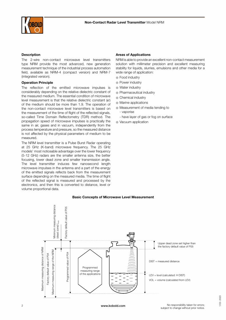
Programmed measuring range
of the applications
Upper dead zone set higher than the factory default value of P05
DIST = measured distance
Max
imum
mea
surin
g di
stan
ce o
f NR
M
Max
imum
mea
surin
g ra
nge
of th
e N
RM
Fact
ory
defa
ult v
alue
of P
04
Pro
gram
med
val
ue o
f P04
Fact
ory
defa
ult v
alue
of P
05
Min
imum
mea
surin
g di
stan
ce
(dea
d zo
ne) L
min
LEV = level (calculated: H DIST)
VOL = volume (calculated from LEV)
Basic Concepts of Microwave Level Measurement
DescriptionThe 2-wire non-contact microwave level transmitters type NRM provide the most advanced, new generation measurement technique of the industrial process automation field, available as NRM-4 (compact version) and NRM-7 (integrated version).
Operation PrincipleThe reflection of the emitted microwave impulses is considerably depending on the relative dielectric constant of the measured medium. The essential condition of microwave level measurement is that the relative dielectric constant (εr) of the medium should be more than 1.9. The operation of the non-contact microwave level transmitters is based on the measurement of the time of flight of the reflected signals, so-called Time Domain Reflectometry (TDR) method. The propagation speed of microwave impulses is practically the same in air, gases and in vacuum, independently from the process temperature and pressure, so the measured distance is not affected by the physical parameters of medium to be measured.The NRM level transmitter is a Pulse Burst Radar operating at 25 GHz (K-band) microwave frequency. The 25 GHz models’ most noticeable advantage over the lower frequency (5-12 GHz) radars are the smaller antenna size, the better focusing, lower dead zone and smaller transmission angle. The level transmitter induces few nanosecond length microwave impulses in the antenna and a part of the energy of the emitted signals reflects back from the measurement surface depending on the measured media. The time of flight of the reflected signal is measured and processed by the electronics, and then this is converted to distance, level or volume proportional data.
Areas of ApplicationsNRM is able to provide an excellent non-contact measurement solution with millimeter precision and excellent measuring stability for liquids, slurries, emulsions and other media for a wide range of application:
OO Food industryOO Power industryOO Water industryOO Pharmaceutical industryOO Chemical industryOO Marine applicationsOO Measurement of media tending to
- vaporise - have layer of gas or fog on surfaceOO Vacuum application
3www.kobold.com 1/0
3 - 2
020
No responsibility taken for errors; subject to change without prior notice.
Non-Contact Radar Level Transmitter Model NRM
Technical Details
Type Integrated (NRM-7)Compact (NRM-4)
Plastic housing
Metal housing High temperature version
Measured values level, distance, volume, mass
Frequency of measurement signal ~25 GHz (K-band)
Measuring range 0.2 -23 m see »Measuring ranges« page 4
Linearity error*<0.5 m: ±25 mm, 0.5-1m: ±15 mm, 1–1.5 m: ±10 mm, 1.5–8 m: ±3 mm, >8 m: ±0.04%
of the measured distance
Min. beam angle11° depending on the antenna
type6° depending on the antenna type
Min. εr of the medium1.9 depending on the meas.
range 1.4 depending on the meas. range, see »Measuring ranges« page 4
Resolution 1 mm
Temperature error (accord. to EN 61298-3)
0.05% FSK / 10 °C (-20 ... +60 °C)
Power supply 20 … 36 VDC, ATEX: 20 … 30 VDC
OutputDigital communication 4-20 mA + HART®
Display NRM-300P graphical display unit (optional)
Measuring frequency 10 … 60 s as per application settings
Antenna diameter 38 mm, 48 mm, 75 mm, 148 mm
Antenna materialantenna (horn, parabolic): stainless steel 1.4571 (316 Ti);
enclosure: PP, PTFE
antenna (horn, parabolic): stainless steel 1.4571 (316 Ti);
enclosure: PTFE
Process temperature-30 … +100 ºC (up to max. 2 min.: 120 ºC);
with PP antenna enclosure: max.: 80 ºC-30 … +180 ºC
Maximal medium pressure 25 bar (at 120 ºC), with plastic antenna enclosure or plastic flange: 3 bar (at 25 ºC)
Ambient temperature -20 … +60 ºC
Process connection thread, flange, Tri-Clamp®, sanitary connection
Protection IP 68 / Ex: IP 67 IP 67
Electrical connection
LiYCY cable 2 x 0.5 mm2
(AWG20) shielded Ø 6 mm standard cable length 5 m
(max. 30 m)
2xM20x1.5 cable glands + internal thread for 2x ½" NPT cable protective pipe, cable outer diameter Ø 7 - 13 mm, wire cross
section: max. 1.5 mm²
Housing material PP PBT paint coated aluminium or stainless steel
Sealing FKM, EPDM
Communication certifications R&TTE, FCC
Weight 1 - 1.6 kg
aluminium 2 - 2.6 kg
stainless steel 3.3 - 3.9 kg
aluminium 2.7 - 3.3 kg
stainless steel 4 - 4.6 kg
* Under reference conditions: Examined in case of proper application settings at 95% sample rate level. The environment should be free of EMC noises and po-wer supply voltage fluctuations in accordance to the standard, under constant temperature. The reflector should be a plane plate reflector with ideal material, surface and dimensions (min. 3 x 3 m). The largest false echo should be 20 dB smaller than the useful echo.
Explosion Protection, Ex Markings, Ex-MIN/MAX-Data
Type Plastic housing compact Metal housing High temperature version with metal housing
IECEx (ia)Ex ia IIB T6 … T5 Ga/Gb
Li: 200 µH, Ci: 16 nF, Ui: 30 V, Ii: 140 mA, Pi: 1 W
Ex ia IIB T6 … T4 Ga
Li: 200 µH, Ci: 16 nF, Ui: 30 V, Ii: 140 mA, Pi: 1 W
Ex ia IIB T6 … T3 Ga
Li: 200 µH, Ci: 16 nF, Ui: 30 V, Ii: 140 mA, Pi: 1 W
ATEX (ia) II 1/2 G Ex ia IIB T6 … T5 Ga/Gb
Li: 200 µH, Ci: 16 nF, Ui: 30 V, Ii: 140 mA, Pi: 1 W
II 1G Ex ia IIB T6 … T4 Ga
Li: 200 µH, Ci: 16 nF, Ui: 30 V, Ii: 140 mA, Pi: 1 W
II 1G Ex ia IIB T6 … T3 Ga
Li: 200 µH, Ci: 16 nF, Ui: 30 V, Ii: 140 mA, Pi: 1 W
4 www.kobold.com 1/0
3 - 2
020
2,5 3,2 8 50
5 m
10 m
15 m
Max. measuring range
18 m20 m
23 m
2 4 5 6,3 10 12 16 20 25 32 40 63 80 100 125
25 m
εr1,61,4 1,8
DN150: Stainless steel parabolic antennaDN80: Stainless steel horn antenna (W S-18 - )DN50: Stainless steel horn antenna (W S-15 - )DN40: Stainless steel horn antenna (W S-14 - )
KM
DN50
DN40
DN 08
DN 015
Max. measurement range
Process Connection
Antenna type
Antenna diameter
DN40 (1½") DN50 (2") DN80 (3") DN150 (6")
Process connection
1½" BSP/NPT 2" Tri-Clamp® DN50 (DIN 11851)
2" BSP/NPT DN80 ... DN150 flanges
Stainless steel (1.4571) horn x x x
PP enclosure x x
PTFE enclosure x x x x
Stainless steel (1.4571) parabolic x
Beam Angle / Dead Zone
Antenna Beam angle Dead zone [mm]
DN40 19° 200
DN40, encapsulated 25°- 27° 300
DN50 16° 200
DN50, encapsulated 25°- 27° 300
DN80 11° 200
DN150 6° 400
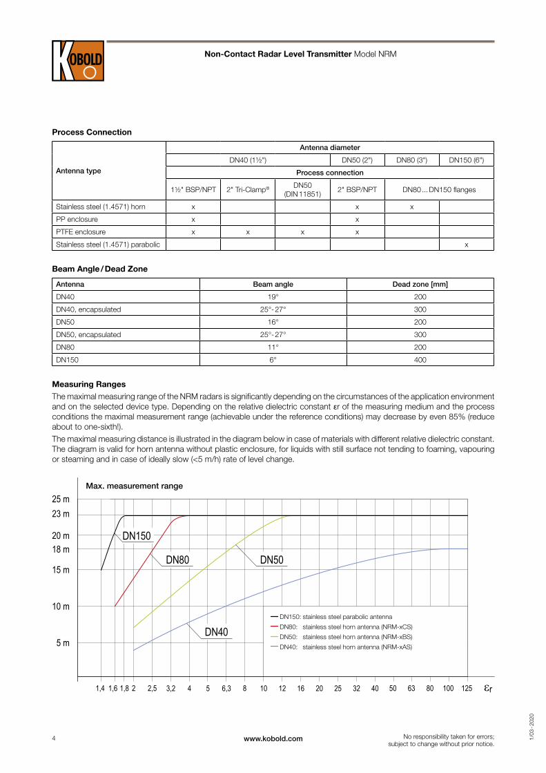
Measuring RangesThe maximal measuring range of the NRM radars is significantly depending on the circumstances of the application environment and on the selected device type. Depending on the relative dielectric constant εr of the measuring medium and the process conditions the maximal measurement range (achievable under the reference conditions) may decrease by even 85% (reduce about to one-sixth!).The maximal measuring distance is illustrated in the diagram below in case of materials with different relative dielectric constant. The diagram is valid for horn antenna without plastic enclosure, for liquids with still surface not tending to foaming, vapouring or steaming and in case of ideally slow (<5 m/h) rate of level change.
Non-Contact Radar Level Transmitter Model NRM
No responsibility taken for errors; subject to change without prior notice.
DN150: stainless steel parabolic antenna
DN80: stainless steel horn antenna (NRM-xCS)
DN50: stainless steel horn antenna (NRM-xBS)
DN40: stainless steel horn antenna (NRM-xAS)
5www.kobold.com 1/0
3 - 2
020
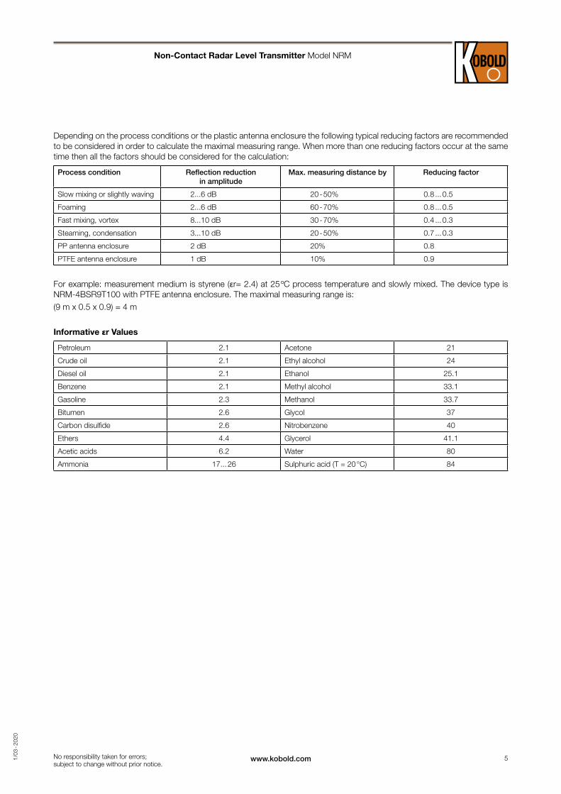
Depending on the process conditions or the plastic antenna enclosure the following typical reducing factors are recommended to be considered in order to calculate the maximal measuring range. When more than one reducing factors occur at the same time then all the factors should be considered for the calculation:
Process condition Reflection reduction in amplitude
Max. measuring distance by Reducing factor
Slow mixing or slightly waving 2...6 dB 20 - 50% 0.8 ... 0.5
Foaming 2...6 dB 60 - 70% 0.8 ... 0.5
Fast mixing, vortex 8...10 dB 30 - 70% 0.4 ... 0.3
Steaming, condensation 3...10 dB 20 - 50% 0.7 ... 0.3
PP antenna enclosure 2 dB 20% 0.8
PTFE antenna enclosure 1 dB 10% 0.9
For example: measurement medium is styrene (εr= 2.4) at 25 ºC process temperature and slowly mixed. The device type is NRM-4BSR9T100 with PTFE antenna enclosure. The maximal measuring range is: (9 m x 0.5 x 0.9) = 4 m
Informative εr Values
Petroleum 2.1 Acetone 21
Crude oil 2.1 Ethyl alcohol 24
Diesel oil 2.1 Ethanol 25.1
Benzene 2.1 Methyl alcohol 33.1
Gasoline 2.3 Methanol 33.7
Bitumen 2.6 Glycol 37
Carbon disulfide 2.6 Nitrobenzene 40
Ethers 4.4 Glycerol 41.1
Acetic acids 6.2 Water 80
Ammonia 17... 26 Sulphuric acid (T = 20 °C) 84
Non-Contact Radar Level Transmitter Model NRM
No responsibility taken for errors; subject to change without prior notice.
6 www.kobold.com 1/0
3 - 2
020
2 3 4 5 61
RELAY
1/2” NPT
Displayeinheit-verbindung
MessverbindungStromschleife
4 ... 20 mA Stromschleifeund Versorgung (HART)
GND
1/2” NPT
M20x1,5M20x1,5
3 42 5U - +
V 200mV
A
24V
250 Ohm HART Modeme.g. HARTCOMM
Ex power supply
Ex Non Ex
V 200mV
A
24V
250 Ohm HART Modeme.g. HARTCOMM
Ex power supply
Ex Non Ex
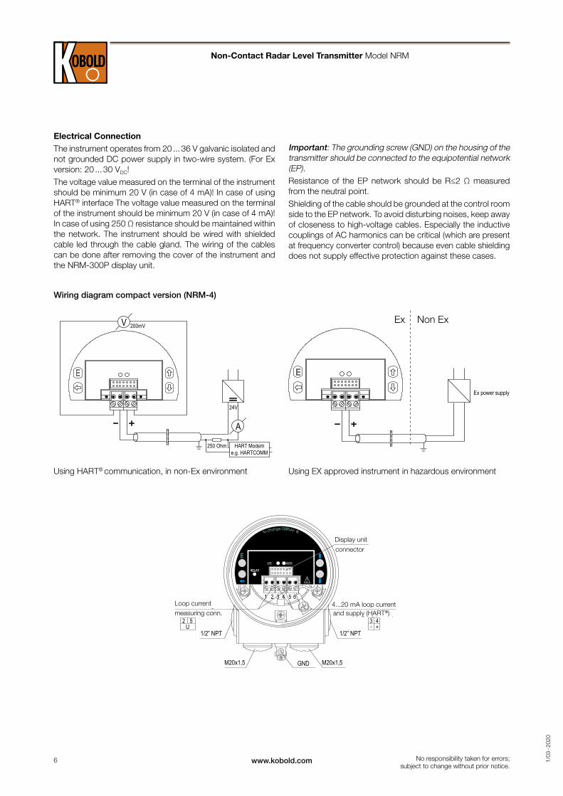
Electrical ConnectionThe instrument operates from 20 ... 36 V galvanic isolated and not grounded DC power supply in two-wire system. (For Ex version: 20 ... 30 VDC!The voltage value measured on the terminal of the instrument should be minimum 20 V (in case of 4 mA)! In case of using HART® interface The voltage value measured on the terminal of the instrument should be minimum 20 V (in case of 4 mA)! In case of using 250 Ω resistance should be maintained within the network. The instrument should be wired with shielded cable led through the cable gland. The wiring of the cables can be done after removing the cover of the instrument and the NRM-300P display unit.
Using HART® communication, in non-Ex environment Using EX approved instrument in hazardous environment
Wiring diagram compact version (NRM-4)
Non-Contact Radar Level Transmitter Model NRM
Display unit
Loop current 4...20 mA loop currentmeasuring conn. and supply (HART®)
connector
No responsibility taken for errors; subject to change without prior notice.
Important: The grounding screw (GND) on the housing of the transmitter should be connected to the equipotential network (EP). Resistance of the EP network should be R≤2 Ω measured from the neutral point. Shielding of the cable should be grounded at the control room side to the EP network. To avoid disturbing noises, keep away of closeness to high-voltage cables. Especially the inductive couplings of AC harmonics can be critical (which are present at frequency converter control) because even cable shielding does not supply effective protection against these cases.
7www.kobold.com 1/0
3 - 2
020
Gelb
GrünGelb
Braun
Weiß
Grün
Verteilerbox
+ Stromversorgung
+ Stromausgang+ HART®
HART®-Modem
IBraunWeiß
Grün
Grün/Gelb
R
GelbTRA
NS
MIT
TER
mA
V200mV
Stromversorgung
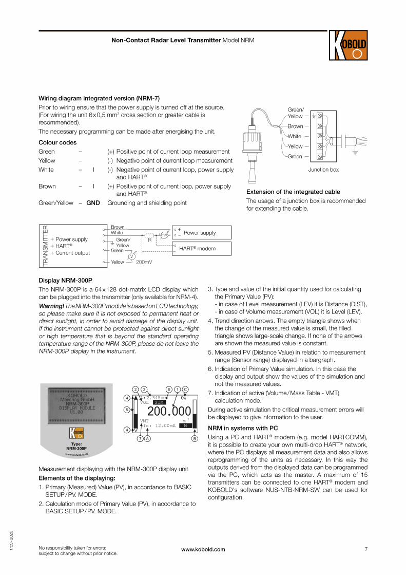
Extension of the integrated cable
The usage of a junction box is recommended for extending the cable.
Wiring diagram integrated version (NRM-7)
Prior to wiring ensure that the power supply is turned off at the source. (For wiring the unit 6 x 0,5 mm2 cross section or greater cable is recommended).The necessary programming can be made after energising the unit.
Colour codes
Green – (+) Positive point of current loop measurementYellow – (-) Negative point of current loop measurementWhite – I (-) Negative point of current loop, power supply
and HART®
Brown – I (+) Positive point of current loop, power supply and HART®
Green/Yellow – GND Grounding and shielding point
Non-Contact Radar Level Transmitter Model NRM
Green/ Yellow
Brown
White
Yellow
Green
Junction box
Power supplyHART®
Current output
Brown Power supply
HART® modem
White
Green
Green/ Yellow
Yellow
No responsibility taken for errors; subject to change without prior notice.
Display NRM-300P
The NRM-300P is a 64 x 128 dot-matrix LCD display which can be plugged into the transmitter (only available for NRM-4).Warning! The NRM-300P module is based on LCD technology, so please make sure it is not exposed to permanent heat or direct sunlight, in order to avoid damage of the display unit. If the instrument cannot be protected against direct sunlight or high temperature that is beyond the standard operating temperature range of the NRM-300P, please do not leave the NRM-300P display in the instrument.
Measurement displaying with the NRM-300P display unitElements of the displaying:
1. Primary (Measured) Value (PV), in accordance to BASIC SETUP / PV. MODE.
2. Calculation mode of Primary Value (PV), in accordance to BASIC SETUP / PV. MODE.
3. Type and value of the initial quantity used for calculating the Primary Value (PV): - in case of Level measurement (LEV) it is Distance (DIST), - in case of Volume measurement (VOL) it is Level (LEV).
4. Trend direction arrows. The empty triangle shows when the change of the measured value is small, the filled triangle shows large-scale change. If none of the arrows are shown the measured value is constant.
5. Measured PV (Distance Value) in relation to measurement range (Sensor range) displayed in a bargraph.
6. Indication of Primary Value simulation. In this case the display and output show the values of the simulation and not the measured values.
7. Indication of active (Volume / Mass Table - VMT) calculation mode.
During active simulation the critical measurement errors will be displayed to give information to the user.
NRM in systems with PC
Using a PC and HART® modem (e.g. model HARTCOMM), it is possible to create your own multi-drop HART® network, where the PC displays all measurement data and also allows reprogramming of the units as necessary. In this way the outputs derived from the displayed data can be programmed via the PC, which acts as the master. A maximum of 15 transmitters can be connected to one HART® modem and KOBOLD's software NUS-NTB-NRM-SW can be used for configuration.
8 www.kobold.com 1/0
3 - 2
020
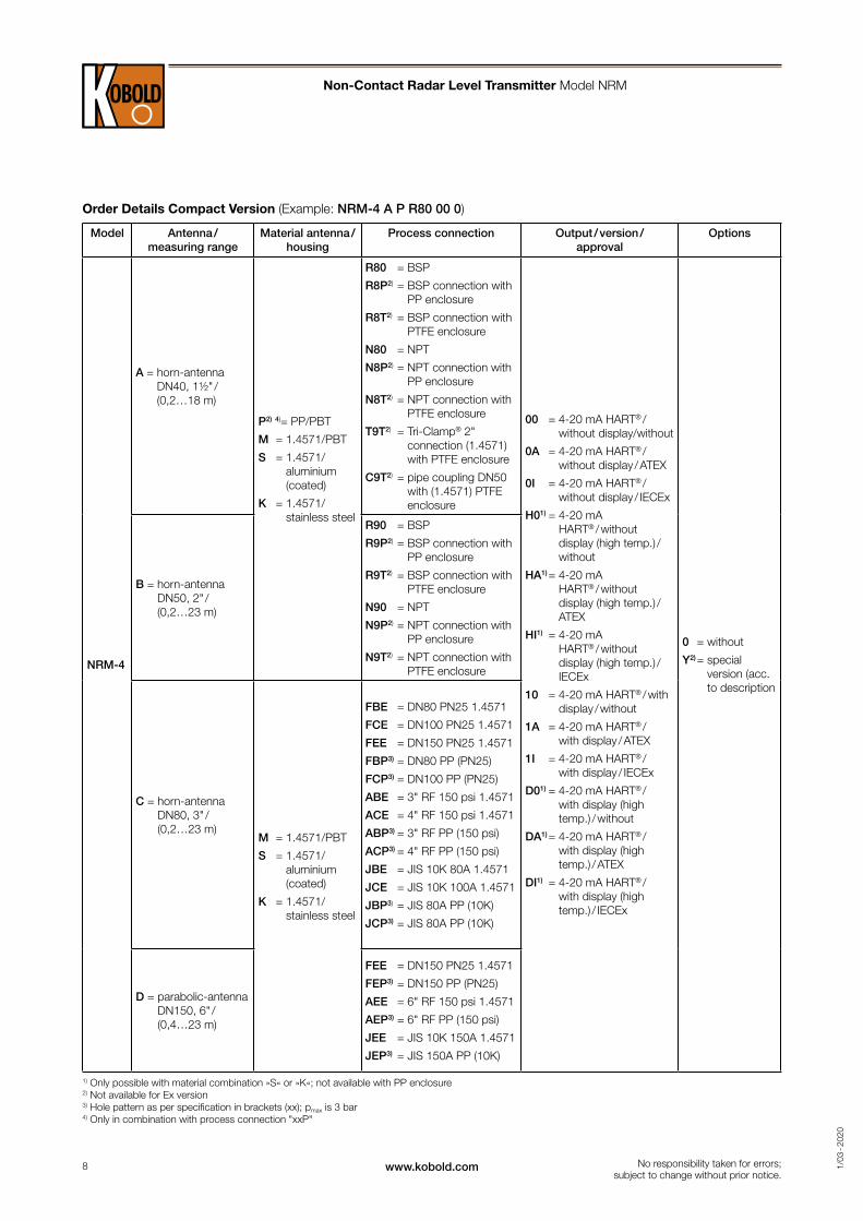
Order Details Compact Version (Example: NRM-4 A P R80 00 0)
Model Antenna / measuring range
Material antenna /housing
Process connection Output / version / approval
Options
NRM-4
A = horn-antenna DN40, 1½" / (0,2…18 m)
P2) 4)= PP/PBT
M = 1.4571/PBT
S = 1.4571/ aluminium (coated)
K = 1.4571/ stainless steel
R80 = BSP
R8P2) = BSP connection with PP enclosure
R8T2) = BSP connection with PTFE enclosure
N80 = NPT
N8P2) = NPT connection with PP enclosure
N8T2) = NPT connection with PTFE enclosure
T9T2) = Tri-Clamp® 2" connection (1.4571) with PTFE enclosure
C9T2) = pipe coupling DN50 with (1.4571) PTFE enclosure
00 = 4-20 mA HART® / without display/without
0A = 4-20 mA HART® / without display / ATEX
0I = 4-20 mA HART® / without display / IECEx
H01) = 4-20 mA HART® / without display (high temp.) / without
HA1) = 4-20 mA HART® / without display (high temp.) / ATEX
HI1) = 4-20 mA HART® / without display (high temp.) / IECEx
10 = 4-20 mA HART® / with display / without
1A = 4-20 mA HART® / with display / ATEX
1I = 4-20 mA HART® / with display / IECEx
D01) = 4-20 mA HART® / with display (high temp.) / without
DA1) = 4-20 mA HART® / with display (high temp.) / ATEX
DI1) = 4-20 mA HART® / with display (high temp.) / IECEx
0 = without
Y2) = special version (acc. to description
B = horn-antenna DN50, 2" / (0,2…23 m)
R90 = BSP
R9P2) = BSP connection with PP enclosure
R9T2) = BSP connection with PTFE enclosure
N90 = NPT
N9P2) = NPT connection with PP enclosure
N9T2) = NPT connection with PTFE enclosure
C = horn-antenna DN80, 3" / (0,2…23 m)
M = 1.4571/PBT
S = 1.4571/ aluminium (coated)
K = 1.4571/ stainless steel
FBE = DN80 PN25 1.4571
FCE = DN100 PN25 1.4571
FEE = DN150 PN25 1.4571
FBP3) = DN80 PP (PN25)
FCP3) = DN100 PP (PN25)
ABE = 3" RF 150 psi 1.4571
ACE = 4" RF 150 psi 1.4571
ABP3) = 3" RF PP (150 psi)
ACP3) = 4" RF PP (150 psi)
JBE = JIS 10K 80A 1.4571
JCE = JIS 10K 100A 1.4571
JBP3) = JIS 80A PP (10K)
JCP3) = JIS 80A PP (10K)
D = parabolic-antenna DN150, 6" / (0,4…23 m)
FEE = DN150 PN25 1.4571
FEP3) = DN150 PP (PN25)
AEE = 6" RF 150 psi 1.4571
AEP3) = 6" RF PP (150 psi)
JEE = JIS 10K 150A 1.4571
JEP3) = JIS 150A PP (10K)
1) Only possible with material combination »S« or »K«; not available with PP enclosure2) Not available for Ex version3) Hole pattern as per specification in brackets (xx); pmax is 3 bar4) Only in combination with process connection "xxP"
Non-Contact Radar Level Transmitter Model NRM
No responsibility taken for errors; subject to change without prior notice.
9www.kobold.com 1/0
3 - 2
020
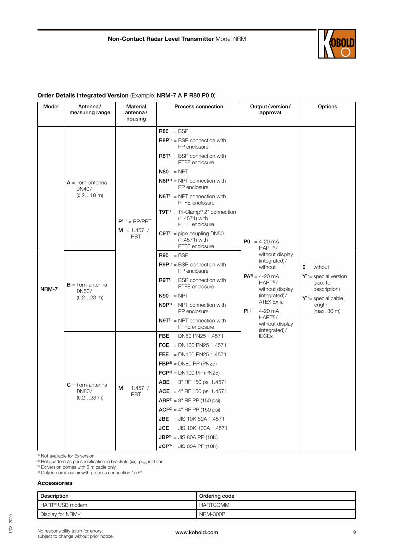
Order Details Integrated Version (Example: NRM-7 A P R80 P0 0)
Model Antenna / measuring range
Material antenna /housing
Process connection Output / version / approval
Options
NRM-7
A = horn-antenna DN40 / (0,2…18 m)
P1) 4)= PP/PBT
M = 1.4571/PBT
R80 = BSP
R8P1) = BSP connection with PP enclosure
R8T1) = BSP connection with PTFE enclosure
N80 = NPT
N8P1) = NPT connection with PP enclosure
N8T1) = NPT connection with PTFE-enclosure
T9T1) = Tri-Clamp® 2" connection (1.4571) with PTFE enclosure
C9T1) = pipe coupling DN50 (1.4571) with PTFE enclosure
P0 = 4-20 mA HART® / without display (integrated) / without
PA3) = 4-20 mA HART® / without display (integrated) / ATEX Ex ia
PI3) = 4-20 mA HART® / without display (integrated) / IECEx
0 = wthout
Y1) = special version (acc. to description)
Y1) = special cable length (max. 30 m)
B = horn-antenna DN50 / (0,2…23 m)
R90 = BSP
R9P1) = BSP connection with PP enclosure
R9T1) = BSP connection with PTFE enclosure
N90 = NPT
N9P1) = NPT connection with PP enclosure
N9T1) = NPT connection with PTFE enclosure
C = horn-antenna DN80 / (0,2…23 m)
M = 1.4571/PBT
FBE = DN80 PN25 1.4571
FCE = DN100 PN25 1.4571
FEE = DN150 PN25 1.4571
FBP2) = DN80 PP (PN25)
FCP2) = DN100 PP (PN25)
ABE = 3" RF 150 psi 1.4571
ACE = 4" RF 150 psi 1.4571
ABP2) = 3" RF PP (150 psi)
ACP2) = 4" RF PP (150 psi)
JBE = JIS 10K 80A 1.4571
JCE = JIS 10K 100A 1.4571
JBP2) = JIS 80A PP (10K)
JCP2) = JIS 80A PP (10K)
1) Not available for Ex version 2) Hole pattern as per specification in brackets (xx); pmax is 3 bar 3) Ex version comes with 5 m cable only 4) Only in combination with process connection "xxP"
Accessories
Description Ordering code
HART® USB modem HARTCOMM
Display for NRM-4 NRM-300P
Non-Contact Radar Level Transmitter Model NRM
No responsibility taken for errors; subject to change without prior notice.

10 www.kobold.com 1/0
3 - 2
020
139
141
2
20
Ø38
BSP 1½"
NPT ½" (2x)
M20 x 1.5(2x)
133
SW 55
L min
M6/SW3
139
141NPT ½" (2x)
M20 x 1.5(2x)
SW65M6/SW3
168
Ø48 L min
20
2
BSP 2"
2
20
Ø38
BSP 1 ½"
133
SW55
L min
M6/SW3
135
2 x NPT ½"
M20 x 1.5 (2x)
137
135
NPT ½" (2x)
M20 x 1.5 (2x)
137
M6/SW3
168
Ø48 L min
20
2
BSP 2"
SW65
139
141
2
20
Ø38
BSP 1½"
NPT ½" (2x)
M20 x 1.5(2x)
133
SW 55
L min
M6/SW3
139
141NPT ½" (2x)
M20 x 1.5(2x)
SW65M6/SW3
168
Ø48 L min
20
2
BSP 2"
2
20
Ø38
BSP 1 ½"
133
SW55
L min
M6/SW3
135
2 x NPT ½"
M20 x 1.5 (2x)
137
135
NPT ½" (2x)
M20 x 1.5 (2x)
137
M6/SW3
168
Ø48 L min
20
2
BSP 2"
SW65
139
141
2
20
Ø38
BSP 1½"
NPT ½" (2x)
M20 x 1.5(2x)
133
SW 55
L min
M6/SW3
139
141NPT ½" (2x)
M20 x 1.5(2x)
SW65M6/SW3
168
Ø48 L min
20
2
BSP 2"
2
20
Ø38
BSP 1 ½"
133
SW55
L min
M6/SW3
135
2 x NPT ½"
M20 x 1.5 (2x)
137
135
NPT ½" (2x)
M20 x 1.5 (2x)
137
M6/SW3
168
Ø48 L min
20
2
BSP 2"
SW65
13914
1
2
20
Ø38
BSP 1½"
NPT ½" (2x)
M20 x 1.5(2x)
133
SW 55
L min
M6/SW3
139
141NPT ½" (2x)
M20 x 1.5(2x)
SW65M6/SW3
168
Ø48 L min
20
2
BSP 2"
2
20
Ø38
BSP 1 ½"
133
SW55
L min
M6/SW3
135
2 x NPT ½"
M20 x 1.5 (2x)
137
135
NPT ½" (2x)
M20 x 1.5 (2x)
137
M6/SW3
168
Ø48 L min
20
2
BSP 2"
SW65
139
139
NPT ½" (2x)
M20 x 1.5 (2x)
M6/SW3
153
SW55
2210
0
Ø44 L min
BSP 1 ½"NPT 1 ½"
SW55
135
NPT ½" (2x)
M20 x 1.5 (2x)
172
22
100
118
Ø44 L min
BSP 1 ½"NPT 1 ½"
SW55
139
139NPT ½" (2x)
M20 x 1.5 (2x)
M6/SW3
194
24
122
Ø54,5
BSP 2"NPT 2"
SW65
SW65
L min
135
NPT ½" (2x)
M20 x 1.5 (2x)
186
24
145
BSP 2"NPT 2"
SW65
122
Ø54,5 L min
139
139
NPT ½" (2x)
M20 x 1.5 (2x)
M6/SW3
153
SW55
2210
0
Ø44 L min
BSP 1 ½"NPT 1 ½"
SW55
135
NPT ½" (2x)
M20 x 1.5 (2x)
172
22
100
118
Ø44 L min
BSP 1 ½"NPT 1 ½"
SW55
139
139NPT ½" (2x)M20 x 1.5 (2x)
M6/SW3
194
24
122
Ø54,5
BSP 2"NPT 2"
SW65
SW65
L min
135
NPT ½" (2x)
M20 x 1.5 (2x)
186
24
145
BSP 2"NPT 2"
SW6512
2
Ø54,5 L min
139
139
NPT ½" (2x)
M20 x 1.5 (2x)
M6/SW3
153
SW55
2210
0
Ø44 L min
BSP 1 ½"NPT 1 ½"
SW55
135
NPT ½" (2x)
M20 x 1.5 (2x)
172
22
100
118
Ø44 L min
BSP 1 ½"NPT 1 ½"
SW55
139
139NPT ½" (2x)
M20 x 1.5 (2x)
M6/SW3
194
24
122
Ø54,5
BSP 2"NPT 2"
SW65
SW65
L min
135
NPT ½" (2x)
M20 x 1.5 (2x)
186
24
145
BSP 2"NPT 2"
SW6512
2
Ø54,5 L min
Dimensions [mm]
Aluminium housing 1½" horn antenna
Aluminium housing 2" horn antenna
Plastic housing 1½" horn antenna
Plastic housing 2" horn antenna
Material of wetted parts 1.4571, PTFE 1.4571, PTFE 1.4571, PTFE 1.4571, PTFE
Process connection 1½" BSP, 1½" NPT 2" BSP, 2" NPT 1½" BSP, 1½" NPT 2" BSP, 2" NPT
Beam angle (-3 dB) 19° 16° 19° 16°
Dead zone Lmin* 200 mm 200 mm 200 mm 200 mm
* Under reference conditions
Aluminium housing 1½" antenna with PP
enclosure
Plastic housing 1½" PP encapsulated
antenna
Aluminium housing 2" antenna with PP
enclosure
Plastic housing 2" PP encapsulated
antenna
Material of wetted parts PP PP PP PP
Process connection 1½" BSP, 1½" NPT 1½" BSP, 1½" NPT 2" BSP, 2" NPT 2" BSP, 2" NPT
Dead zone Lmin* 300 mm 300 mm 300 mm 300 mm
* Under reference conditions
Non-Contact Radar Level Transmitter Model NRM
No responsibility taken for errors; subject to change without prior notice.
11www.kobold.com 1/0
3 - 2
020
Ø38
Ø95
296
150
BSP 1½"
NPT 1½"
L min
Ø95
331
185
BSP 2"
NPT 2"
L minØ48
Ø95
314
168
L min
SW55
BSP 1½"
NPT 1½"
Ø95
354
208
L min
SW65
BSP 2"
NPT 2"
Ø38
Ø95
296
150
BSP 1½"
NPT 1½"
L min
Ø95
331
185
BSP 2"
NPT 2"
L minØ48
Ø95
314
168
L min
SW55
BSP 1½"
NPT 1½"
Ø95
354
208
L min
SW65
BSP 2"
NPT 2"
Ø38
Ø95
296
150
BSP 1½"
NPT 1½"
L min
Ø95
331
185
BSP 2"
NPT 2"
L minØ48
Ø95
314
168
L min
SW55
BSP 1½"
NPT 1½"
Ø95
354
208
L min
SW65
BSP 2"
NPT 2"
Ø38
Ø95
296
150
BSP 1½"
NPT 1½"
L min
Ø9533
1
185
BSP 2"
NPT 2"
L minØ48
Ø95
314
168
L min
SW55
BSP 1½"
NPT 1½"
Ø95
354
208
L min
SW65
BSP 2"
NPT 2"
139
141NPT ½" (2x)
M20 x 1.5 (2x)
M6/SW3
2
151
63 82
Ø45 L min
SW55
Ø64 / 2 " Tri-Clamp®
SW55
M6/SW3
2
151
63 82
Ø45 L min
SW55
Ø64 / 2 " Tri-Clamp®
SW55
135
NPT ½" (2x)
M20 x 1.5 (2x)
137
139
141
NPT ½" (2x)
M20 x 1.5 (2x)
M6/SW3
2
151
74 93
Ø45 L min
SW55
Rd78x1/6 (DN50 DIN11851)
SW55
135
NPT ½" (2x)
M20 x 1.5 (2x)
137
M6/SW3
2
151
74 93
Ø45 L min
SW55
Rd78x1/6 (DN50 DIN11851)
SW55
139
141NPT ½" (2x)
M20 x 1.5 (2x)
M6/SW3
2
151
63 82
Ø45 L min
SW55
Ø64 / 2 " Tri-Clamp®
SW55
M6/SW3
2
151
63 82
Ø45 L min
SW55
Ø64 / 2 " Tri-Clamp®
SW55
135
NPT ½" (2x)
M20 x 1.5 (2x)
137
139
141
NPT ½" (2x)
M20 x 1.5 (2x)
M6/SW3
2
151
74 93
Ø45 L min
SW55
Rd78x1/6 (DN50 DIN11851)
SW55
135
NPT ½" (2x)
M20 x 1.5 (2x)13
7
M6/SW3
2
151
74 93
Ø45 L min
SW55
Rd78x1/6 (DN50 DIN11851)
SW55
139
141NPT ½" (2x)
M20 x 1.5 (2x)
M6/SW3
2
151
63 82
Ø45 L min
SW55
Ø64 / 2 " Tri-Clamp®
SW55
M6/SW3
2
151
63 82
Ø45 L min
SW55
Ø64 / 2 " Tri-Clamp®
SW55
135
NPT ½" (2x)
M20 x 1.5 (2x)
137
139
141
NPT ½" (2x)
M20 x 1.5 (2x)
M6/SW3
2
151
74 93
Ø45 L min
SW55
Rd78x1/6 (DN50 DIN11851)
SW55
135
NPT ½" (2x)
M20 x 1.5 (2x)
137
M6/SW3
2
151
74 93
Ø45 L min
SW55
Rd78x1/6 (DN50 DIN11851)
SW55
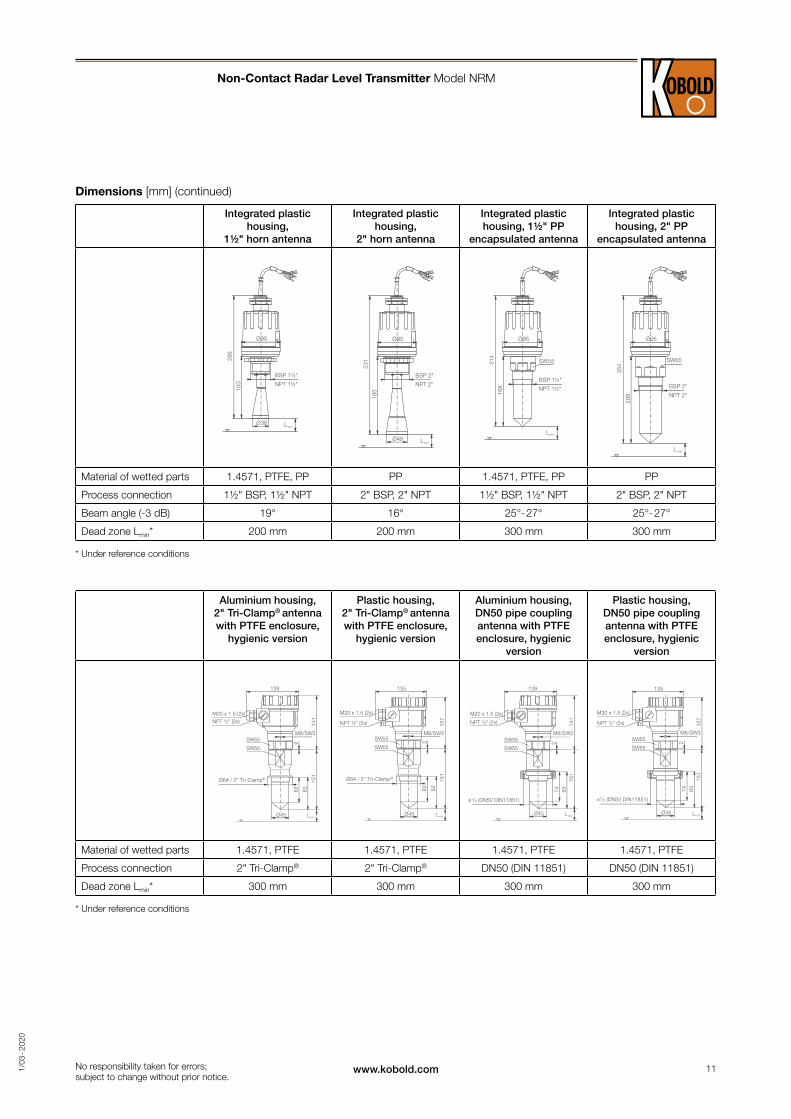
Dimensions [mm] (continued)
Integrated plastic housing,
1½" horn antenna
Integrated plastic housing,
2" horn antenna
Integrated plastic housing, 1½" PP
encapsulated antenna
Integrated plastic housing, 2" PP
encapsulated antenna
Material of wetted parts 1.4571, PTFE, PP PP 1.4571, PTFE, PP PP
Process connection 1½" BSP, 1½" NPT 2" BSP, 2" NPT 1½" BSP, 1½" NPT 2" BSP, 2" NPT
Beam angle (-3 dB) 19° 16° 25°- 27° 25°- 27°
Dead zone Lmin* 200 mm 200 mm 300 mm 300 mm
* Under reference conditions
Aluminium housing, 2" Tri-Clamp® antenna with PTFE enclosure,
hygienic version
Plastic housing, 2" Tri-Clamp® antenna with PTFE enclosure,
hygienic version
Aluminium housing, DN50 pipe coupling antenna with PTFE enclosure, hygienic
version
Plastic housing, DN50 pipe coupling antenna with PTFE enclosure, hygienic
version
Material of wetted parts 1.4571, PTFE 1.4571, PTFE 1.4571, PTFE 1.4571, PTFE
Process connection 2" Tri-Clamp® 2" Tri-Clamp® DN50 (DIN 11851) DN50 (DIN 11851)
Dead zone Lmin* 300 mm 300 mm 300 mm 300 mm
* Under reference conditions
Non-Contact Radar Level Transmitter Model NRM
No responsibility taken for errors; subject to change without prior notice.
12 www.kobold.com 1/0
3 - 2
020
139
165NPT ½" (2x)
M20 x 1.5 (2x)
M6/SW3
2SW55
240
DN80 PN25DN100 PN 25DN125 PN25DN150 PN25
3" RF 150psi4" RF 150psi5" RF 150psi6" RF 150psi
JIS 10K80AJIS 10K100AJIS 10K125AJIS 10K150A
Ø75 L min
139
226
NPT ½" (2x)
M20 x 1.5 (2x)
20
Ø38
BSP 1 ½"
NPT 1 ½"
133
L min
2
M6/SW3SW55
Ø100
139
226
NPT ½" (2x)
M20 x 1.5 (2x)
Ø100
168
Ø48 L min
20
2
BSP 2"
NPT 2"
SW60 M6/SW3
139
NPT ½" (2x)
M20 x 1.5 (2x)
2
M6/SW3SW55
Ø100
Ø75
DN80 PN25DN100 PN 25DN125 PN25DN150 PN25
3" RF 150psi4" RF 150psi5" RF 150psi6" RF 150psi
JIS 10K80AJIS 10K100AJIS 10K125AJIS 10K150A
250
L min
240
139
226
NPT ½" (2x)
M20 x 1.5 (2x)2
M6/SW3SW55
Ø100
151
63 82
Ø45 L min
Ø64 / 2 " Tri-Clamp®
SW55
Ø47,3
139
226
NPT ½" (2x)
M20 x 1.5 (2x)
20
Ø38
BSP 1 ½"
NPT 1 ½"
133
L min
2
M6/SW3SW55
Ø100
139
226
NPT ½" (2x)
M20 x 1.5 (2x)
Ø100
168
Ø48 L min
20
2
BSP 2"
NPT 2"
SW60 M6/SW3
139
NPT ½" (2x)
M20 x 1.5 (2x)
2
M6/SW3SW55
Ø100
Ø75
DN80 PN25DN100 PN 25DN125 PN25DN150 PN25
3" RF 150psi4" RF 150psi5" RF 150psi6" RF 150psi
JIS 10K80AJIS 10K100AJIS 10K125AJIS 10K150A
250
L min
240
139
226
NPT ½" (2x)
M20 x 1.5 (2x)
2
M6/SW3SW55
Ø100
151
63 82
Ø45 L min
Ø64 / 2 " Tri-Clamp®
SW55
Ø47,3
139 (~5.5")
141
(~
5.6"
)
NPT ½" (2x)
M20 x 1.5 (2x)
M6/SW3
2 (~
0.08
")
SW55
148 (~5.83")
DN150 PN256" RF 150 PSIJIS 10K150A
85 (
~5.
2")
SW 3
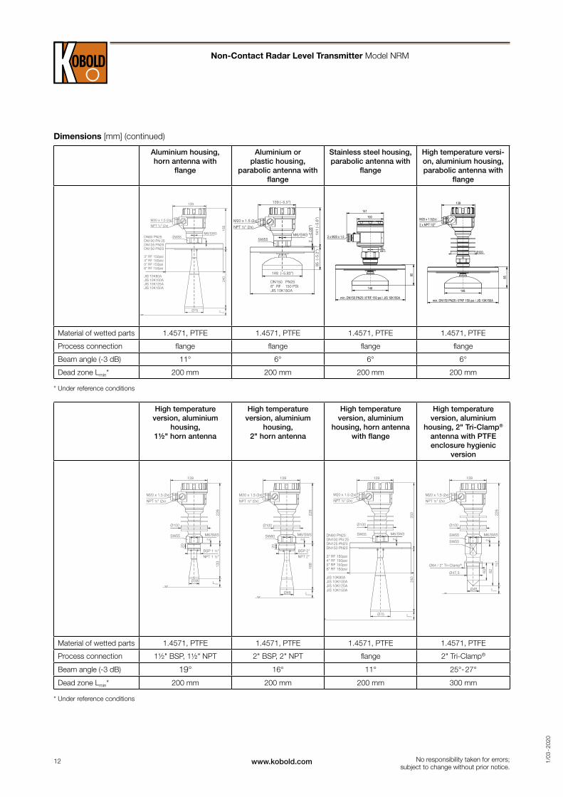
Dimensions [mm] (continued)
Aluminium housing, horn antenna with
flange
Aluminium or plastic housing,
parabolic antenna with flange
Stainless steel housing, parabolic antenna with
flange
High temperature versi-on, aluminium housing, parabolic antenna with
flange
Material of wetted parts 1.4571, PTFE 1.4571, PTFE 1.4571, PTFE 1.4571, PTFE
Process connection flange flange flange flange
Beam angle (-3 dB) 11° 6° 6° 6°
Dead zone Lmin* 200 mm 200 mm 200 mm 200 mm
* Under reference conditions
High temperature version, aluminium
housing, 1½" horn antenna
High temperature version, aluminium
housing, 2" horn antenna
High temperature version, aluminium
housing, horn antenna with flange
High temperature version, aluminium
housing, 2" Tri-Clamp®
antenna with PTFE enclosure hygienic
version
Material of wetted parts 1.4571, PTFE 1.4571, PTFE 1.4571, PTFE 1.4571, PTFE
Process connection 1½" BSP, 1½" NPT 2" BSP, 2" NPT flange 2" Tri-Clamp®
Beam angle (-3 dB) 19° 16° 11° 25°- 27°
Dead zone Lmin* 200 mm 200 mm 200 mm 300 mm
* Under reference conditions
Non-Contact Radar Level Transmitter Model NRM
No responsibility taken for errors; subject to change without prior notice.