non-display portable user guide - rádiostanice · non-display portable user guide ... firmware...
TRANSCRIPT

pltres-ES ru ar-EGit-ITfr-FRde-DEen
PROFESSIONAL DIGITAL TWO-WAY RADIOS
MOTOTRBOTM
DP1400NON-DISPLAY PORTABLEUSER GUIDE
source-EMEA.fm Page 1 Monday, December 1, 2014 11:49 AM

Contents
English
i
mmable Buttons . . . . . . . . . . . . . . . . . . . . . . . 7ignable Radio Functions . . . . . . . . . . . . . . . . . 7gnable Settings or Utility Functions . . . . . . . . . 8o-Talk (PTT) Button . . . . . . . . . . . . . . . . . . . . 8ing Between Conventional Analog and l Mode . . . . . . . . . . . . . . . . . . . . . . . . . . . . . . . 9
ng Status Indicators . . . . . . . . . . . . . . . . . . 10dicator . . . . . . . . . . . . . . . . . . . . . . . . . . . . . 10Tones . . . . . . . . . . . . . . . . . . . . . . . . . . . . . . 11or Tones . . . . . . . . . . . . . . . . . . . . . . . . . . . . 11
g and Making Calls . . . . . . . . . . . . . . . . . . 12ng a Channel . . . . . . . . . . . . . . . . . . . . . . . . 12ing and Responding to a Radio Call . . . . . . 13LED lights up solid green while the radio is mitting. . . . . . . . . . . . . . . . . . . . . . . . . . . . . . 13iving and Responding to a Group Call . . . . . 13iving and Responding to a Private Call . . . 14iving an All Call . . . . . . . . . . . . . . . . . . . . . . 15 a Radio Call . . . . . . . . . . . . . . . . . . . . . . . . 15king a Group Call . . . . . . . . . . . . . . . . . . . . . 16king a Private Call . . . . . . . . . . . . . . . . . . . . 16ing a Selective Call . . . . . . . . . . . . . . . . . . . 17und . . . . . . . . . . . . . . . . . . . . . . . . . . . . . . . 17
ring Features . . . . . . . . . . . . . . . . . . . . . . . . 18
DP1400_EMEA.book Page i Monday, December 15, 2014 3:25 PM
ContentsThis User Guide contains all the information you need to use the MOTOTRBO DP1400 Portable Radio.
Important Safety Information . . . . . . . . . . . . . . . . . iiiRF Energy Exposure and Product Safety Guide for Portable Two-Way Radios . . . . . . . . . . . . . . . .iii
Firmware Version . . . . . . . . . . . . . . . . . . . . . . . . . . . iiiComputer Software Copyrights . . . . . . . . . . . . . . . ivHandling Precautions . . . . . . . . . . . . . . . . . . . . . . . . vGetting Started . . . . . . . . . . . . . . . . . . . . . . . . . . . . . . 1
How to Use This Guide . . . . . . . . . . . . . . . . . . . . . . . 1What Your Dealer/System Administrator Can Tell You . . . . . . . . . . . . . . . . . . . . . . . . . . . . . . 1
Preparing Your Radio for Use . . . . . . . . . . . . . . . . . . 2Charging the Battery . . . . . . . . . . . . . . . . . . . . . . . . . 2Attaching the Battery . . . . . . . . . . . . . . . . . . . . . . . . . 2Attaching the Antenna . . . . . . . . . . . . . . . . . . . . . . . . 3Attaching the Belt Clip . . . . . . . . . . . . . . . . . . . . . . . . 3Powering Up the Radio . . . . . . . . . . . . . . . . . . . . . . . 4Adjusting the Volume . . . . . . . . . . . . . . . . . . . . . . . . 4
Identifying Radio Controls . . . . . . . . . . . . . . . . . . . . 5Radio Controls . . . . . . . . . . . . . . . . . . . . . . . . . . . . . 6
Progra AssAssi
Push-TSwitchDigita
IdentifyiLED InAudio Indicat
ReceivinSelectiReceiv
The transReceReceRece
MakingMaMa
MakTalkaroMonito
E
i
Monitoring a Channel . . . . . . . . . . . . . . . . . . . . . 18 Exiting an Emergency Mode After Sending the ency Alarm . . . . . . . . . . . . . . . . . . . . . . . . 27saging Features . . . . . . . . . . . . . . . . . . . 28
ng a Quick Text Message . . . . . . . . . . . . . 28 . . . . . . . . . . . . . . . . . . . . . . . . . . . . . . . . . 28crambling . . . . . . . . . . . . . . . . . . . . . . . . 29rker . . . . . . . . . . . . . . . . . . . . . . . . . . . . . . 29d Lock Features . . . . . . . . . . . . . . . . . . . . 30ing the Radio from Password . . . . . . . . . 30ing the Radio from Locked State . . . . . . . 31ge Transponder System (ARTS) . . . . . . . 31
. . . . . . . . . . . . . . . . . . . . . . . . . . . . . . . . . . 32 the Squelch Level . . . . . . . . . . . . . . . . . 32 the Power Level . . . . . . . . . . . . . . . . . . . 32g the Voice Operating Transmission (VOX) e On or Off . . . . . . . . . . . . . . . . . . . . . . . . 33
nnouncement . . . . . . . . . . . . . . . . . . . . . 33g Trill Enhancement On or Off . . . . . . . . . 33g Radio Tones/Alerts On or Off . . . . . . . . 34ing the Battery Strength . . . . . . . . . . . . . . 34
arranty . . . . . . . . . . . . . . . . . . . . . . . . . 35arranty . . . . . . . . . . . . . . . . . . . . . . . . . . . 35
DP1400_EMEA.book Page ii Monday, December 15, 2014 3:25 PM
Con
tent
s
nglish
i
Permanent Monitor . . . . . . . . . . . . . . . . . . . . . . . 19
Advanced Features . . . . . . . . . . . . . . . . . . . . . . . . . 20Scan Lists . . . . . . . . . . . . . . . . . . . . . . . . . . . . . . . . 20Scan . . . . . . . . . . . . . . . . . . . . . . . . . . . . . . . . . . . . 21
Starting and Stopping Scan . . . . . . . . . . . . . . . . 21Responding to a Transmission During a Scan . . 21Deleting a Nuisance Channel . . . . . . . . . . . . . . . 22Restoring a Nuisance Channel . . . . . . . . . . . . . . 22
Vote Scan . . . . . . . . . . . . . . . . . . . . . . . . . . . . . . . 23Call Indicator Settings . . . . . . . . . . . . . . . . . . . . . . 23
Escalating Alarm Tone Volume . . . . . . . . . . . . . . 23Call Alert Operation . . . . . . . . . . . . . . . . . . . . . . . . 23
Receiving and Responding to a Call Alert . . . . . 23Making a Call Alert with the One Touch Access Button . . . . . . . . . . . . . . . . . . . . . . . . . . 24
Emergency Operation . . . . . . . . . . . . . . . . . . . . . . 24Receiving an Emergency Alarm . . . . . . . . . . . . . 25Exiting Emergency Mode After Receiving the Emergency Alarm . . . . . . . . . . . . . . . . . . . . . . . . 25Sending an Emergency Alarm . . . . . . . . . . . . . . 25Sending an Emergency Alarm with Call . . . . . . . 25Sending an Emergency Alarm with Voice to Follow . . . . . . . . . . . . . . . . . . . . . . . . . . . . . . . . . 26Reinitiating an Emergency Mode . . . . . . . . . . . . 27
EmergText Mes
SendiPrivacy Analog SLone WoPasswor
AccessUnlock
Auto-RanUtilities
SettingSettingTurninFeaturVoice ATurninTurninCheck
Batteries WLimited W

Important Safety Inform
ation
English
iii
re Versionures described in the following sections are by the software version R01.01.01 of the radio. your dealer or system administrator for more all the features supported.
DP1400_EMEA.book Page iii Monday, December 15, 2014 3:25 PM
Important Safety Information
RF Energy Exposure and Product Safety Guide for Portable Two-Way Radios
ATTENTION!
This radio is restricted to Occupational use only. Before using the radio, read the RF Energy Exposure and Product Safety Guide for Portable Two-Way Radios which contains important operating instructions for safe usage and RF energy awareness and control for Compliance with applicable standards and Regulations.
For a list of Motorola-approved antennas, batteries, and other accessories, visit the following website:
http://www.motorolasolutions.com
FirmwaAll the featsupported Check withdetails for
E
i
TM voice coding Technology embodied in s protected by intellectual property rights ent rights, copyrights and trade secrets of Systems, Inc.
ding Technology is licensed solely for use mmunications Equipment. The user of this
s explicitly prohibited from attempting to verse engineer, or disassemble the Object
ny other way convert the Object Code into a ble form.
s. #5,870,405, #5,826,222, #5,754,974, #5,715,365, #5,649,050, #5,630,011, #5,517,511, #5,491,772, #5,247,579, nd #5,195,166.
rce Software Legal NoticesProduct contains Open Source Software. For ion regarding licenses, acknowledgements, ight notices, and other usage terms, refer to the n for this Motorola Product at:
line.motorolasolutions.com
DP1400_EMEA.book Page iv Monday, December 15, 2014 3:25 PM
Com
pute
r Sof
twar
e C
opyr
ight
s
nglish
v
Computer Software CopyrightsThe Motorola products described in this manual may include copyrighted Motorola computer programs stored in semiconductor memories or other media. Laws in the United States and other countries preserve for Motorola certain exclusive rights for copyrighted computer programs including, but not limited to, the exclusive right to copy or reproduce in any form the copyrighted computer program. Accordingly, any copyrighted Motorola computer programs contained in the Motorola products described in this manual may not be copied, reproduced, modified, reverse-engineered, or distributed in any manner without the express written permission of Motorola. Furthermore, the purchase of Motorola products shall not be deemed to grant either directly or by implication, estoppel, or otherwise, any license under the copyrights, patents or patent applications of Motorola, except for the normal non-exclusive license to use that arises by operation of law in the sale of a product.
The AMBE+2this product iincluding patDigital Voice
This voice cowithin this CoTechnology idecompile, reCode, or in ahuman-reada
U.S. Pat. No#5,701,390, #5,581,656, #5,226,084 a
Open SouThis Motorola more informatrequired copyrDocumentatio
https://emeaon

Handling Precautions
English
v
DP1400_EMEA.book Page v Monday, December 15, 2014 3:25 PM
Handling PrecautionsThe MOTOTRBO DP1400 Portable radio meets IP54 specifications with the antenna and dust cover attached. Your radio limits protection against dust and water exposure.
• Keep your radio clean and exposure to water should be avoided to help ensure proper functionality and performance.
• To clean the exterior surfaces of the radio, use a diluted solution of mild dishwashing detergent and fresh water (i.e. one teaspoon of detergent to one gallon of water).
• These surfaces should be cleaned whenever a periodic visual inspection reveals the presence of smudges, grease, and/or grime.
The effects of certain chemicals and their vapors can have harmful results on certain plastics. Avoid using aerosol sprays, tuner cleaners and other chemicals.

E
v
DP1400_EMEA.book Page vi Monday, December 15, 2014 3:25 PM
Han
dlin
g Pr
ecau
tions
nglish
i
Notes
Getting Started
English
1
Getting StartedTake a moment to review the following:How to Use This Guide . . . . . . . . . . . . . . . . . . . . . . . . . page 1What Your Dealer/System Administrator
Can Tell You. . . . . . . . . . . . . . . . . . . . . . . . . . . . . . . . page 1
How to Use This Guide
This User Guide covers the basic operation of the MOTOTRBO Non-Display Portables.
However, your dealer or system administrator may have customized your radio for your specific needs. Check with your dealer or system administrator for more information.
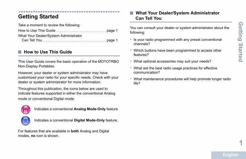
Throughout this publication, the icons below are used to indicate features supported in either the conventional Analog mode or conventional Digital mode:
For features that are available in both Analog and Digital modes, no icon is shown.
What Your Dealer/System Administrator Can Tell You
You can consult your dealer or system administrator about the following:
• Is your radio programmed with any preset conventional channels?
• Which buttons have been programmed to access other features?
• What optional accessories may suit your needs?
• What are the best radio usage practices for effective communication?
• What maintenance procedures will help promote longer radio life?
Indicates a conventional Analog Mode-Only feature.
Indicates a conventional Digital Mode-Only feature.
DP1400_EMEA.book Page 1 Monday, December 15, 2014 3:25 PM
E
2
g the Battery
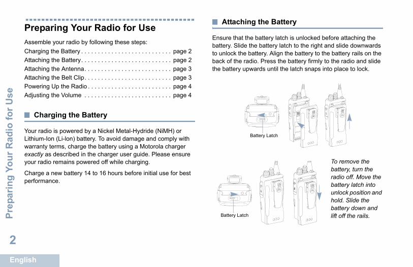
e battery latch is unlocked before attaching the he battery latch to the right and slide downwards attery. Align the battery to the battery rails on the io. Press the battery firmly to the radio and slide ards until the latch snaps into place to lock.
To remove the battery, turn the radio off. Move the battery latch into unlock position and hold. Slide the battery down and lift off the rails.
Battery Latch
DP1400_EMEA.book Page 2 Monday, December 15, 2014 3:25 PM
Prep
arin
g Yo
ur R
adio
for U
se
nglish
Preparing Your Radio for UseAssemble your radio by following these steps:Charging the Battery . . . . . . . . . . . . . . . . . . . . . . . . . . . page 2Attaching the Battery. . . . . . . . . . . . . . . . . . . . . . . . . . . page 2Attaching the Antenna. . . . . . . . . . . . . . . . . . . . . . . . . . page 3Attaching the Belt Clip. . . . . . . . . . . . . . . . . . . . . . . . . . page 3Powering Up the Radio . . . . . . . . . . . . . . . . . . . . . . . . . page 4Adjusting the Volume . . . . . . . . . . . . . . . . . . . . . . . . . . page 4
Charging the Battery
Your radio is powered by a Nickel Metal-Hydride (NiMH) or Lithium-Ion (Li-lon) battery. To avoid damage and comply with warranty terms, charge the battery using a Motorola charger exactly as described in the charger user guide. Please ensure your radio remains powered off while charging.
Charge a new battery 14 to 16 hours before initial use for best performance.
Attachin
Ensure that thbattery. Slide tto unlock the bback of the radthe battery upw
Battery Latch

Preparing Your Radio for U
se
English
3
ing the Belt Clip
oves on the clip n the battery and wards until you
he clip, press the away from the g a key. Then upwards and
he radio.
DP1400_EMEA.book Page 3 Monday, December 15, 2014 3:25 PM
Attaching the Antenna
With the radio turned off, set the antenna in its receptacle and turn clockwise.
To remove the antenna, turn the antenna counterclockwise.
Attach
Align the growith those opress downhear a click.
To remove tbelt clip tab battery usinslide the clipaway from t
If the antenna needs to be replaced, ensure that only antennas are used. Neglecting this will damage your radio.
E
4
g the Volume
e volume, turn the On/Off/Volume Control Knob
e volume, turn this knob counterclockwise.
radio can be programmed to have a minimum e offset where the volume level cannot be turned fully. Check with your dealer or system nistrator for more information.
On/Off/Volume Control Knob
DP1400_EMEA.book Page 4 Monday, December 15, 2014 3:25 PM
Prep
arin
g Yo
ur R
adio
for U
se
nglish
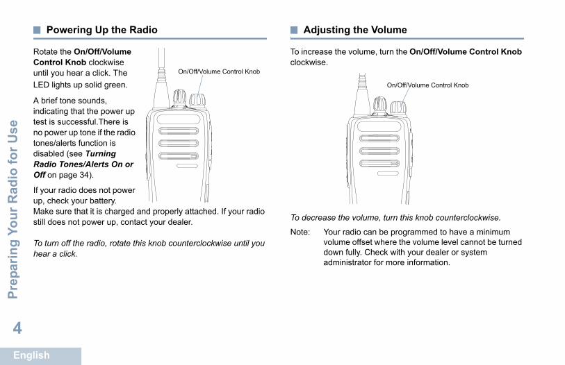
Powering Up the Radio
Rotate the On/Off/Volume Control Knob clockwise until you hear a click. The LED lights up solid green.
A brief tone sounds, indicating that the power up test is successful.There is no power up tone if the radio tones/alerts function is disabled (see Turning Radio Tones/Alerts On or Off on page 34).
If your radio does not power up, check your battery. Make sure that it is charged and properly attached. If your radio still does not power up, contact your dealer.
To turn off the radio, rotate this knob counterclockwise until you hear a click.
Adjustin
To increase thclockwise.
To decrease th
Note: Your volumdownadmi
On/Off/Volume Control Knob
Identifying Radio C
ontrols
English
5
DP1400_EMEA.book Page 5 Monday, December 15, 2014 3:25 PM
Identifying Radio ControlsTake a moment to review the following:Radio Controls. . . . . . . . . . . . . . . . . . . . . . . . . . . . . . . . page 6Programmable Buttons . . . . . . . . . . . . . . . . . . . . . . . . . page 7Push-To-Talk (PTT) Button . . . . . . . . . . . . . . . . . . . . . . page 8Switching Between Conventional Analog and
Digital Mode. . . . . . . . . . . . . . . . . . . . . . . . . . . . . . . . page 9
E
6
r
icator
Volume Control Knob
l Selector Knob
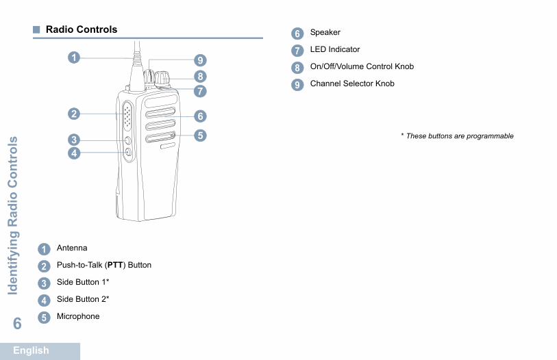
* These buttons are programmable
DP1400_EMEA.book Page 6 Monday, December 15, 2014 3:25 PM
Iden
tifyi
ng R
adio
Con
trol
s
nglish
Radio Controls
Antenna
Push-to-Talk (PTT) Button
Side Button 1*
Side Button 2*
Microphone
8
6
5
2
1
43
7
9
12345
Speake
LED Ind
On/Off/
Channe
6789
Identifying Radio C
ontrols
English
7
hannel Delete – Temporarily removes an hannel, except for the Selected Channel, from the e Selected Channel refers to the user’s selected bination from which scan is initiated.
Access – Directly initiates a predefined roup Call, a Call Alert.
Monitor– Monitors a selected channel for all radio nction is disabled.
– Toggles privacy on or off.
lkaround– Toggles between using a repeater and ting directly with another radio.
gles scan on or off.
cement On/Off – Toggles trill enhancement on or
uncement On/Off – Toggles Voice Announcement
ating Transmission (VOX) – Toggles VOX on or
ngth – Indicates battery strength via the LED
DP1400_EMEA.book Page 7 Monday, December 15, 2014 3:25 PM
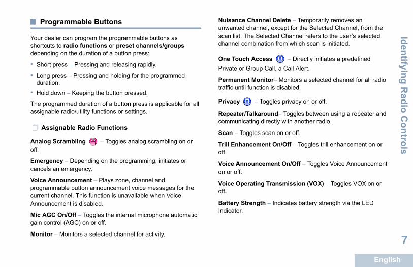
Programmable Buttons
Your dealer can program the programmable buttons as shortcuts to radio functions or preset channels/groups depending on the duration of a button press:
• Short press – Pressing and releasing rapidly.
• Long press – Pressing and holding for the programmed duration.
• Hold down – Keeping the button pressed.
The programmed duration of a button press is applicable for all assignable radio/utility functions or settings.
Assignable Radio Functions
Analog Scrambling – Toggles analog scrambling on or off.
Emergency – Depending on the programming, initiates or cancels an emergency.
Voice Announcement – Plays zone, channel and programmable button announcement voice messages for the current channel. This function is unavailable when Voice Announcement is disabled.
Mic AGC On/Off – Toggles the internal microphone automatic gain control (AGC) on or off.
Monitor – Monitors a selected channel for activity.
Nuisance Cunwanted cscan list. Thchannel com
One TouchPrivate or G
Permanenttraffic until fu
Privacy
Repeater/Tacommunica
Scan – Tog
Trill Enhanoff.
Voice Annoon or off.
Voice Operoff.
Battery StreIndicator.

E
8
-Talk (PTT) Button
n on the io serves oses:
is in e PTT s the radio o other call.
old down to talk. PTT ten.
one ishen the PTT button is pressed.
is not in progress, the PTT button is used to make ee Making a Radio Call on page 15).
programming, if the Talk Permit Tone or the PTT
is enabled, wait until the short alert tone ends
PTT Button
DP1400_EMEA.book Page 8 Monday, December 15, 2014 3:25 PM
Iden
tifyi
ng R
adio
Con
trol
s
nglish
Assignable Settings or Utility Functions
All Tones/Alerts – Toggles all tones and alerts on or off.
Analog Scrambling Codes – Toggles scrambling codes between 3.29KHz and 3.39KHz.
Power Level – Toggles transmit power level between high and low.
Squelch – Toggles squelch level between tight and normal.
Push-To
The PTT buttoside of the radtwo basic purp
• While a callprogress, thbutton allowto transmit tradios in the
Press and hPTT button Release thebutton to lis
The microph activated w
• While a call a new call (s
Depending on
Sidetone before talking.

Identifying Radio C
ontrols
English
9
ing Between Conventional Analog and Mode
el in your radio igured as a l analog or l digital channel.
r Analog-only ios, each channel only be figured as a ventional analog nnel.
nnel Selector tch between an analog or a digital channel.
hing from digital to analog mode, certain features ble.
lso has features available in both analog and digital ver, the minor differences in the way each feature
NOT affect the performance of your radio. A ense Key sold separately is required to upgrade
radios to digital radios.
ur radio also switches between digital and analog des during a dual mode scan (see Scan on e 21).
Channel Selector Knob
DP1400_EMEA.book Page 9 Monday, December 15, 2014 3:25 PM
During a call, if the Channel Free Indication feature is enabled on your radio (programmed by your dealer), you will hear a short alert tone the moment the target radio (the radio that is receiving your call) releases the PTT button, indicating the channel is free for you to respond.
You will also hear a continuous talk prohibit tone, if your call is interrupted, indicating that you should release the PTT button, for example when the radio receives an Emergency Call.
SwitchDigital
Each channcan be confconventionaconventiona
NOTE: Foradcanconconcha
Use the ChaKnob to swi
When switcare unavaila
Your radio amode. Howeworks does Software Licanalog-only
NOTE: Yomopag
E
10
Double blinking yellow – Indicates radio has yet to respond to ert, or radio is locked.
Radio is powering up, or transmitting. Also harge of the battery when Battery Strength button
n – Radio is receiving a non-privacy-enabled call ing activity over the air.
ng green – Radio is receiving a privacy-enabled
in conventional mode, when the LED blinks , it indicates the radio detects activity over the air. o the nature of the digital protocol, this activity or may not affect the radio's programmed nel.
DP1400_EMEA.book Page 10 Monday, December 15, 2014 3:25 PM
Iden
tifyi
ng S
tatu
s In
dica
tors
nglish
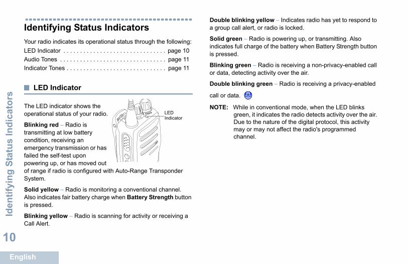
Identifying Status IndicatorsYour radio indicates its operational status through the following:LED Indicator . . . . . . . . . . . . . . . . . . . . . . . . . . . . . . . page 10Audio Tones . . . . . . . . . . . . . . . . . . . . . . . . . . . . . . . . page 11Indicator Tones . . . . . . . . . . . . . . . . . . . . . . . . . . . . . . page 11
LED Indicator
The LED indicator shows the operational status of your radio.
Blinking red – Radio is transmitting at low battery condition, receiving an emergency transmission or has failed the self-test upon powering up, or has moved out of range if radio is configured with Auto-Range Transponder System.
Solid yellow – Radio is monitoring a conventional channel. Also indicates fair battery charge when Battery Strength button is pressed.
Blinking yellow – Radio is scanning for activity or receiving a Call Alert.
a group call al
Solid green –indicates full cis pressed.
Blinking greeor data, detect
Double blinki
call or data.
NOTE: WhilegreenDue tmay chan
LED Indicator

Identifying Status Indicators
English
11
tor Tones
tone Low pitched tone
Positive Indicator Tone
Negative Indicator Tone
DP1400_EMEA.book Page 11 Monday, December 15, 2014 3:25 PM
Audio Tones
Alert tones provide you with audible indications of the radio’s status or the radio’s response to data received.
Indica
High pitched
Continuous Tone A monotone sound. Sounds continuously until termination.
Periodic Tone Sounds periodically depending on the duration set by the radio. Tone starts, stops, and repeats itself.
Repetitive Tone A single tone that repeats itself until it is terminated by the user.
Momentary Tone Sounds only once for a short period of time defined by the radio.

E
12
g a Channel
are sent and received on a channel. Depending configuration, each channel may have been ifferently to support different groups of users or ifferent features. Select the relevant channel you
smit or receive on.
annel Selector Knob to select the number that he channel, radio ID, or group ID.
Channel Selector Knob
DP1400_EMEA.book Page 12 Monday, December 15, 2014 3:25 PM
Rec
eivi
ng a
nd M
akin
g C
alls
nglish
Receiving and Making CallsOnce you understand how your MOTOTRBO Portable is configured, you are ready to use your radio.
Use this navigation guide to familiarize yourself with the basic Call features:Selecting a Channel . . . . . . . . . . . . . . . . . . . . . . . . . . page 12Receiving and Responding to a Radio Call. . . . . . . . . page 13Making a Radio Call . . . . . . . . . . . . . . . . . . . . . . . . . . page 15Talkaround . . . . . . . . . . . . . . . . . . . . . . . . . . . . . . . . . page 17Monitoring Features . . . . . . . . . . . . . . . . . . . . . . . . . . page 18
Selectin
Transmissionson your radio’sprogrammed dsupplied with drequire to tran
Procedure:Turn the Chrepresents t
Receiving and M
aking Calls
English
13
e Privacy on page 28 for more information.
ng and Responding to a Group Call
call from a group of users, your radio must be s part of that group.
blinks green. Your radio unmutes and the incoming ds through the radio's speaker.
nd, hold the radio vertically 1 to 2 inches .0 cm) from your mouth.
e Channel Free Indication feature is enabled, you a short alert tone the moment the transmitting radio the PTT button, indicating the channel is free for spond.e PTT button to respond to the call.
lights up solid green.
the Talk Permit Tone to finish (if enabled) and speak to the microphone.
it for the PTT Sidetone to finish (if enabled) and early into the microphone.
the PTT button to listen.
DP1400_EMEA.book Page 13 Monday, December 15, 2014 3:25 PM
Receiving and Responding to a Radio Call
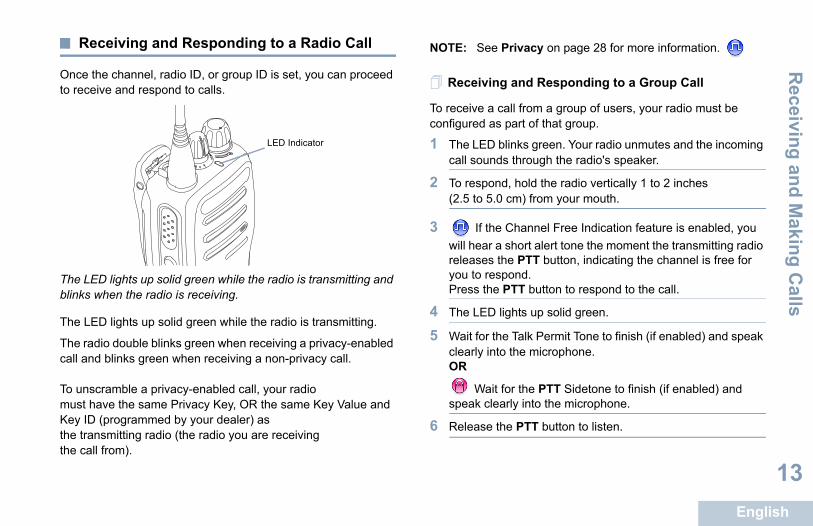
Once the channel, radio ID, or group ID is set, you can proceed to receive and respond to calls.
The LED lights up solid green while the radio is transmitting and blinks when the radio is receiving.
The LED lights up solid green while the radio is transmitting.
The radio double blinks green when receiving a privacy-enabled call and blinks green when receiving a non-privacy call.
To unscramble a privacy-enabled call, your radio must have the same Privacy Key, OR the same Key Value and Key ID (programmed by your dealer) as the transmitting radio (the radio you are receiving the call from).
NOTE: Se
Receivi
To receive aconfigured a
1 The LEDcall soun
2 To respo(2.5 to 5
3 If thwill hearreleasesyou to rePress th
4 The LED
5 Wait for clearly inOR
Waspeak cl
6 Release
LED Indicator
E
14
7 If there is no voice activity for a predetermined period of 7 If there is no voice activity for a predetermined period of all ends.
Private Call on page 16 for details on making a
g and Responding to a Selective Call ll is a call from an individual radio to another
o. It is a Private Call on an analog system.
eive a Selective Call:
links green. Your radio unmutes and the incoming through the radio's speaker.
, hold the radio vertically 1 to 2 inches cm) from your mouth.
TT button to respond to the call. The LED lights een.
Talk Permit Tone to finish (if enabled) and speak the microphone.
e PTT button to listen.
o voice activity for a predetermined period of all ends.
Selective Call on page 17 for details on making ll.
DP1400_EMEA.book Page 14 Monday, December 15, 2014 3:25 PM
Rec
eivi
ng a
nd M
akin
g C
alls
nglish
time, the call ends.
See Making a Group Call on page 16 for details on making a Group Call.
Receiving and Responding to a Private Call
A Private Call is a call from an individual radio to another individual radio.
Procedure:
When you receive a private call:
1 The LED blinks green. Your radio unmutes and the incoming call sounds through the radio's speaker.
2 To respond, hold the radio vertically 1 to 2 inches (2.5 to 5.0 cm) from your mouth.
3 If the Channel Free Indication feature is enabled, you will hear a short alert tone the moment the transmitting radio releases the PTT button, indicating the channel is free for you to respond.
4 Press the PTT button to respond to the call. The LED lights up solid green.
5 Wait for the Talk Permit Tone to finish (if enabled) and speak clearly into the microphone.
6 Release the PTT button to listen.
time, the c
See Making aPrivate Call.
ReceivinA Selective Caindividual radi
Procedure:
When you rec
1 The LED bcall sounds
2 To respond(2.5 to 5.0
3 Press the Pup solid gr
4 Wait for theclearly into
5 Release th
6 If there is ntime, the c
See Making aa Selective Ca
Receiving and M
aking Calls
English
15
a Radio Call
ect a channel, radio ID or group ID by using:
nel Selector Knob.
med One Touch Access button.
r radio must have the Privacy feature enabled on channel to send a privacy-enabled transmission. ly target radios with the same Privacy Key as your io will be able to unscramble the transmission.
e Privacy on page 28 for more information. e One Touch Access feature allows you to make a up or Private Call to a predefined ID easily. This ture can be assigned to a short or long grammable button press.You can ONLY have one assigned to a One Touch Access button. Your io can have multiple One Touch Access buttons grammed.
DP1400_EMEA.book Page 15 Monday, December 15, 2014 3:25 PM
Receiving an All CallAn All Call is a call from an individual radio to every radio on the channel. It is used to make important announcements requiring the user’s full attention.
Procedure:When you receive an All Call:1 A tone sounds and the LED blinks green. Your radio
unmutes and the incoming call sounds through the radio's speaker.
2 An All Call does not wait for a predetermined period of time before ending.
If the Channel Free Indication feature is enabled, you will hear a short alert tone the moment the transmitting radio releases the PTT button, indicating the channel is now available for use.
You cannot respond to an All Call.
NOTE: The radio stops receiving the All Call if you switch to a different channel while receiving the call.During an All Call, you will not be able to use any programmed button functions until the call ends.
Making
You can sel
• The Chan
• A program
NOTE: YoutheOnrad
SeThGrofeaproID radpro

E
16
hannel Free Indication feature is enabled, you short alert tone the moment the target radio e PTT button, indicating the channel is free for ond. Press the PTT button to respond.
o voice activity for a predetermined period of all ends.
Private Call
receive and/or respond to a Private Call authorized individual radio, your radio ammed for you to initiate a Private Call.
types of Private Calls. The first type, where a check is performed prior to setting up the call,
r sets up the call immediately.
ese call types can be programmed to your radio .
gative indicator tone, when you make a Private ne Touch Access button or the Channel , if this feature is not enabled.
lert features to contact an individual radio. See ration on page 23 for more information.
DP1400_EMEA.book Page 16 Monday, December 15, 2014 3:25 PM
Rec
eivi
ng a
nd M
akin
g C
alls
nglish
Making a Group CallTo make a call to a group of users, your radio must be configured as part of that group.
Procedure:
1 Select the channel with the active group alias or ID. See Selecting a Channel on page 12.ORPress the programmed One Touch Access button.
2 Hold the radio vertically 1 to 2 inches (2.5 to 5.0 cm) from your mouth.
3 Press the PTT button to make the call. The LED lights up solid green.
4 Wait for the Talk Permit Tone to finish (if enabled) and speak clearly into the microphone.OR
Wait for the PTT Sidetone to finish (if enabled) and speak clearly into the microphone.
5 Release the PTT button to listen. When the target radio responds, the LED blinks green.
6 If the Cwill hear areleases thyou to respORIf there is ntime, the c
Making a
While you caninitiated by anmust be progr
There are tworadio presencewhile the othe
Only one of thby your dealer
You hear a neCall via the OSelector Knob
Use the Call ACall Alert Ope
Receiving and M
aking Calls
English
17
a Selective Call rivate Call, while you can receive and/or respond to Call initiated by an authorized individual radio, your e programmed for you to initiate a Selective Call.
e channel with the active radio alias or ID. See g a Channel on page 12.
radio vertically 1 to 2 inches (2.5 to 5.0 cm) from uth.
e PTT button to make the call. The LED lights up en.
the Talk Permit Tone to finish (if enabled) and speak to the microphone.
the PTT button to listen. When the target radio s, the LED blinks green.
s no voice activity for a predetermined period of call ends.
und
tinue to communicate when your repeater is not r when your radio is out of the repeater’s range but g range of other radios. This is called “talkaround”.
DP1400_EMEA.book Page 17 Monday, December 15, 2014 3:25 PM
Procedure:
1 Select the channel with the active radio alias or ID. See Selecting a Channel on page 12.ORPress the programmed One Touch Access button.
2 Hold the radio vertically 1 to 2 inches (2.5 to 5.0 cm) from your mouth.
3 Press the PTT button to make the call. The LED lights up solid green.
4 Wait for the Talk Permit Tone to finish (if enabled) and speak clearly into the microphone.
5 Release the PTT button to listen. When the target radio responds, the LED blinks green.
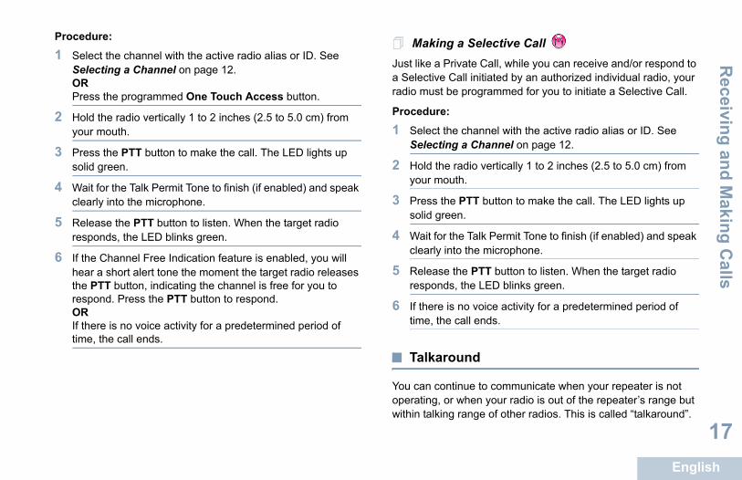
6 If the Channel Free Indication feature is enabled, you will hear a short alert tone the moment the target radio releases the PTT button, indicating the channel is free for you to respond. Press the PTT button to respond.ORIf there is no voice activity for a predetermined period of time, the call ends.
MakingJust like a Pa Selective radio must b
Procedure:
1 Select thSelectin
2 Hold theyour mo
3 Press thsolid gre
4 Wait for clearly in
5 Releaserespond
6 If there itime, the
Talkaro
You can conoperating, owithin talkin
E
18
Procedure: ing Features
g a Channelor feature to make sure a channel is free before
hold the programmed Monitor button and listen
adio activity, total silence or “white noise”, on how your radio is programmed.
ot hear radio activity (that is, channel is free), TT button to talk and release it to listen.
DP1400_EMEA.book Page 18 Monday, December 15, 2014 3:25 PM
Rec
eivi
ng a
nd M
akin
g C
alls
nglish
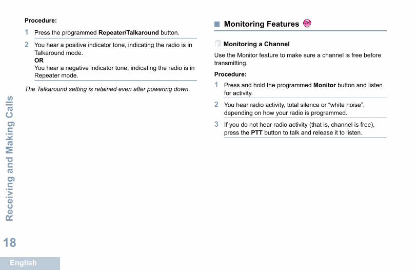
1 Press the programmed Repeater/Talkaround button.
2 You hear a positive indicator tone, indicating the radio is in Talkaround mode.ORYou hear a negative indicator tone, indicating the radio is in Repeater mode.
The Talkaround setting is retained even after powering down.
Monitor
MonitorinUse the Monittransmitting.
Procedure:
1 Press and for activity.
2 You hear rdepending
3 If you do npress the P
Receiving and M
aking Calls
English
19
DP1400_EMEA.book Page 19 Monday, December 15, 2014 3:25 PM
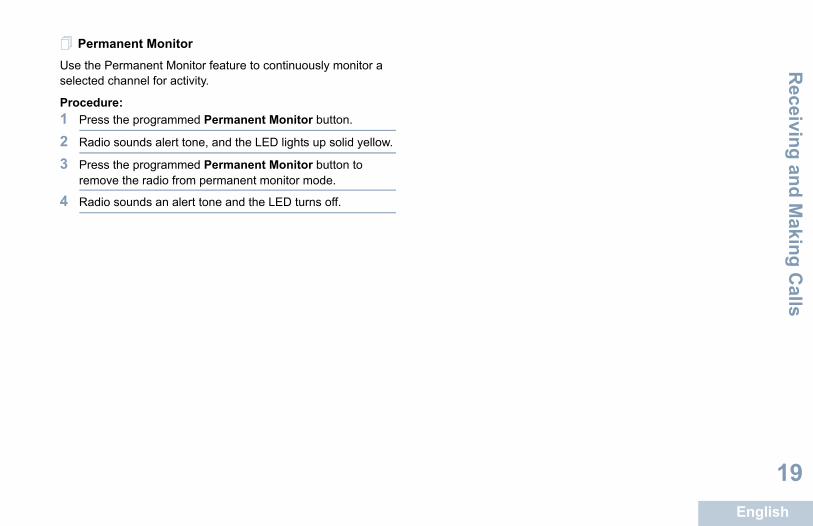
Permanent MonitorUse the Permanent Monitor feature to continuously monitor a selected channel for activity.
Procedure:1 Press the programmed Permanent Monitor button.
2 Radio sounds alert tone, and the LED lights up solid yellow.
3 Press the programmed Permanent Monitor button to remove the radio from permanent monitor mode.
4 Radio sounds an alert tone and the LED turns off.

E
20
Scan Lists
created and assigned to individual channels/adio scans for voice activity by cycling through the sequence specified in the scan list for the current
ports up to 250 scan lists, with a maximum of 16 list. Each scan list shall support a mixture of both ital entries.
DP1400_EMEA.book Page 20 Monday, December 15, 2014 3:25 PM
Adv
ance
d Fe
atur
es
nglish
Advanced FeaturesUse this navigation guide to learn more about advanced features available with your radio:Scan Lists . . . . . . . . . . . . . . . . . . . . . . . . . . . . . . . . . . page 20Scan . . . . . . . . . . . . . . . . . . . . . . . . . . . . . . . . . . . . . . page 21Call Indicator Settings . . . . . . . . . . . . . . . . . . . . . . . . . page 23Call Alert Operation. . . . . . . . . . . . . . . . . . . . . . . . . . . page 23Emergency Operation . . . . . . . . . . . . . . . . . . . . . . . . . page 24Text Messaging Features . . . . . . . . . . . . . . . . . . . . . . page 28Privacy . . . . . . . . . . . . . . . . . . . . . . . . . . . . . . . . . . . . page 28Lone Worker . . . . . . . . . . . . . . . . . . . . . . . . . . . . . . . . page 29Password Lock Features. . . . . . . . . . . . . . . . . . . . . . . page 30Auto-Range Transponder System (ARTS) . . . . . . . . . page 31Utilities. . . . . . . . . . . . . . . . . . . . . . . . . . . . . . . . . . . . . page 32
Scan lists are groups. Your rchannel/groupchannel.
Your radio supmembers in a analog and dig
Advanced Features
English
21
and Stopping Scan
e programmed Scan button.
Channel Selector Knob to select a channel with n enabled.
can is enabled, the LED blinks yellow and you hear e indicator tone.
can is disabled, the LED turns off and you hear a indicator tone.
ding to a Transmission During a Scanning, your radio stops on a channel/group where tected. The radio stays on that channel for a
d time period known as “hang time”.
radio vertically 1 to 2 inches (2.5 to 5.0 cm) from uth.
e Channel Free Indication feature is enabled, you a short alert tone the moment the transmitting radio the PTT button, indicating the channel is free for spond.
DP1400_EMEA.book Page 21 Monday, December 15, 2014 3:25 PM
Scan
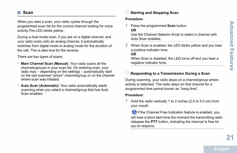
When you start a scan, your radio cycles through the programmed scan list for the current channel looking for voice activity.The LED blinks yellow.
During a dual mode scan, if you are on a digital channel, and your radio locks onto an analog channel, it automatically switches from digital mode to analog mode for the duration of the call. This is also true for the reverse.
There are two types of scans:
• Main Channel Scan (Manual): Your radio scans all the channels/groups in your scan list. On entering scan, your radio may – depending on the settings – automatically start on the last scanned “active” channel/group or on the channel where scan was initiated.
• Auto Scan (Automatic): Your radio automatically starts scanning when you select a channel/group that has Auto Scan enabled.
StartingProcedure:
1 Press thORUse the Auto Sca
2 When Sa positivORWhen Snegative
ResponDuring scanactivity is deprogramme
Procedure:
1 Hold theyour mo
If thwill hearreleasesyou to re
E
22
2 Press the PTT button during hang time. The LED lights up Nuisance Channelntinually generates unwanted calls or noise
sance” channel), you can temporarily remove the nnel from the scan list.
does not apply to the channel designated as the nel.
radio “locks on to” an unwanted or nuisance ress the programmed Nuisance Channel Delete l you hear a tone.
e Nuisance Channel Delete button. The hannel is deleted.
a Nuisance Channel
deleted nuisance channel, do one of the
io off and power it on again, OR
tart a scan via the programmed Scan button, OR
channel via the Channel Selector Knob.
DP1400_EMEA.book Page 22 Monday, December 15, 2014 3:25 PM
Adv
ance
d Fe
atur
es
nglish
solid green.
3 Wait for the Talk Permit Tone to finish (if enabled) and speak clearly into the microphone.OR
Wait for the PTT Sidetone to finish (if enabled) and speak clearly into the microphone.
4 Release the PTT button to listen.
5 If you do not respond within the hang time, the radio returns to scanning other channels/groups.
Deleting aIf a channel co(termed a “nuiunwanted cha
This capabilitySelected Chan
Procedure:
1 When yourchannel, pbutton unti
2 Release thnuisance c
RestoringProcedure: To restore thefollowing:
• Turn the rad
• Stop and res
• Change the

Advanced Features
English
23
dicator Settings
on or off the ringing tones for a received Private rning Radio Tones/Alerts On or Off on page 34).
ing Alarm Tone Volumean be programmed by your dealer to continually en a radio call remains unanswered. This is done cally increasing the alarm tone volume over time.
is known as Escalert.
ert Operation
ging enables you to alert a specific radio user to call en they are able to do so. This feature is accessible mmed One Touch Access button.
ng and Responding to a Call Alert
eceive a Call Alert page:
r a repetitive tone. The LED blinks yellow.
e PTT button within four (4) seconds of receiving a t page to respond to the Private Call.
DP1400_EMEA.book Page 23 Monday, December 15, 2014 3:25 PM
Vote Scan
Vote Scan provides you with wide area coverage in areas where there are multiple base stations transmitting identical information on different analog channels.
Your radio scans analog channels of multiple base stations and performs a voting process to select the strongest received signal. Once that is established, your radio unmutes to transmissions from that base station.
The LED blinks yellow during the Vote Scan operation.
To respond to a transmission during a Vote Scan, follow the same procedures as Responding to a Transmission During a Scan on page 21.
Call In
You can turnCall (see Tu
EscalatYour radio calert you whby automati
This feature
Call Al
Call Alert payou back whvia a progra
ReceiviProcedure:When you r
1 You hea
2 Press thCall Aler
E
24
cy Operation
Alarm is used to indicate a critical situation. You iate an Emergency at any time, in any state, even activity on the current channel.
ports three Emergency Alarms:
Alarm
Alarm with Call
Alarm with Voice to Follow
ch alarm has the following types:
adio transmits an alarm signal and shows audio l indicators.
io transmits an alarm signal without any audio or tors. Radio receives calls without any sound radio’s speaker, until you press the PTT button to all.
Voice – Radio transmits an alarm signal without r visual indicators, but allow incoming calls to gh the radio’s speaker.
DP1400_EMEA.book Page 24 Monday, December 15, 2014 3:25 PM
Adv
ance
d Fe
atur
es
nglish
Making a Call Alert with the One Touch Access
Button
Procedure:
1 Press the programmed One Touch Access button to make a Call Alert to the predefined ID.
2 The LED lights up solid green when your radio is sending the Call Alert.
3 If the Call Alert acknowledgement is received, two chirps sound.ORIf the Call Alert acknowledgement is not received, a low-pitch tone sounds.
Emergen
An Emergencyare able to initwhen there is
Your radio sup
• Emergency
• Emergency
• Emergency
In addition, ea
• Regular – Rand/or visua
• Silent – Radvisual indicathrough the initiate the c
• Silent with any audio osound throu

Advanced Features
English
25
an Emergency Alarm allows you to send an Emergency Alarm, a non-, which triggers an alert indication on a group of
e programmed Emergency On button.
lights up solid green.
Emergency Alarm acknowledgment is received, rgency tone sounds. The LED blinks green.
dio does not receive an Emergency Alarm edgement, and after all retries have been d, a low-pitch tone sounds.
its the Emergency Alarm mode.
is set to Silent, it will not display any audio or visual ring Emergency mode.
an Emergency Alarm with Call
allows you to send an Emergency Alarm to a group on acknowledgement by a radio within the group,
radios can communicate over a programmed channel.
DP1400_EMEA.book Page 25 Monday, December 15, 2014 3:25 PM
Receiving an Emergency AlarmWhen your radio receives an Emergency Alarm, a tone sounds and the LED blinks red until you exit the Emergency mode. Perform one of the following actions to silence the tone:
• Press the PTT button to call the group of radios which received the Emergency Alarm.
• Press any programmable button.
• Exit Emergency mode.
• Your radio automatically acknowledges the Emergency Alarm (if enabled).
Exiting Emergency Mode After Receiving the Emergency Alarm
Exit the Emergency mode by performing one of the following actions:
• Changing the channel.
• Powering down the radio.
• Pressing the Emergency Off button.
• Pressing the Emergency On button. This action clears the alarm indication and initiates an emergency transmission.
SendingThis featurevoice signalradios.
Procedure:
1 Press th
2 The LED
3 When anthe EmeORIf your raacknowlexhauste
4 Radio ex
If your radioindicators du
Sending
This featureof radios. Upthe group ofEmergency
E
26
Procedure: allowing you to communicate with the group of radios without TT button.
microphone state is also known as “hot mic”.
accessories may not support “hot mic”. Check our dealer or system administrator for more ation.
e PTT button during the programmed hot mic eriod, the radio ignores the PTT press and ergency mode.
press the PTT button during hot mic, and ue to press it after the hot mic duration expires, dio continues to transmit until you release the utton.
rogrammed Emergency On button.
ghts up solid green.
e sounds, speak clearly into the microphone. mic has been enabled, the radio automatically ithout a PTT press until the hot mic duration
mitting, the LED lights up solid green.
utomatically stops transmitting when:ycling duration between hot mic and receiving s, if Emergency Cycle Mode is enabled.
DP1400_EMEA.book Page 26 Monday, December 15, 2014 3:25 PM
Adv
ance
d Fe
atur
es
nglish
1 Press the programmed Emergency On button.
2 The LED lights up solid green.
3 When an Emergency Alarm acknowledgment is received, the Emergency tone sounds. The LED blinks green.
4 Hold the radio vertically 1 to 2 inches (2.5 to 5.0 cm) from your mouth.
5 Press the PTT button to make the call. The LED lights up solid green.
6 Wait for the Talk Permit Tone to finish (if enabled) and speak clearly into the microphone.Release the PTT button to listen.
7 When the channel is free for you to respond, a short alert
tone sounds. ( if the Channel Free Indication feature is enabled). Press the PTT button to respond. OROnce your call ends, press Emergency Off button to exit the Emergency mode.
Sending an Emergency Alarm with Voice to Follow
This feature allows you to send an Emergency Alarm to a group of radios. Your radio’s microphone is automatically activated,
pressing the P
This activated
NOTE: Somewith yinform
If you press thtransmission premains in Em
NOTE: If youcontinthe raPTT b
Procedure:
1 Press the p
2 The LED li
3 Once a tonWhen hot transmits wexpires.While trans
4 The radio aOnce the ccalls expireOR
Advanced Features
English
27
ge the channel while the radio is in Emergency is exits the Emergency mode. If Emergency Alarm is n this new channel, the radio reinitiates Emergency.
the programmed Emergency On button during an y initiation/transmission state. This causes the
xit this state, and to reinitiate Emergency.
an Emergency Mode After Sending the ncy Alarm
s feature is only applicable to the radio sending the ergency Alarm.
xits Emergency mode when one of the following
y Alarm acknowledgement is received (for cy Alarm only), OR
mergency Exit Telegram is received, OR
to send the alarm have been exhausted, OR
rgency Off button is pressed.
adio off and then power it on again if your radio has rammed to remain on the Emergency Revert ven after acknowledgement is received. our radio is powered off, it exits the Emergency de. The radio will not reinitiate the Emergency mode omatically when it is turned on again.
DP1400_EMEA.book Page 27 Monday, December 15, 2014 3:25 PM
Once the hot mic duration expires, if Emergency Cycle Mode is disabled.
5 To transmit again, press the PTT button.ORPress the programmed Emergency Off button to exit the Emergency mode.
If your radio is set to Silent, it will not display any audio or visual indicators during Emergency mode, or allow any received calls to sound through the radio’s speaker, until the programmed hot mic transmission period is over, and you press the PTT button.
If your radio is set to Silent with Voice, it will not display any audio or visual indicators during Emergency mode when you are making the call with hot mic, but allow sound through the radio’s speaker when the target radio responds after the programmed hot mic transmission period is over. The indicators will only appear when you press the PTT button.
NOTE: If the Emergency Alarm request fails, the radio does not retry to send the request, and enters the hot mic state directly.
Reinitiating an Emergency ModeNOTE: This feature is only applicable to the radio sending the
Emergency Alarm.
There are two instances where this can happen:
• You chanmode. Thenabled o
• You pressEmergencradio to e
Exiting Emerge
NOTE: ThiEm
Your radio eoccurs:
• EmergencEmergen
• An E
• All retries
• The Eme
• Turn the rbeen progchannel e
NOTE: If ymoaut

E
28
feature helps to prevent eavesdropping by sers on a channel by the use of a software based
lution. The signaling and user identification ansmission are not scrambled.
st have privacy enabled on the channel to send a d transmission, although this is not a necessary r receiving a transmission. While on a privacy el, the radio is still able to receive clear transmissions.Your radio supports only Basic
a privacy-enabled call or data transmission, your programmed to have the same Privacy Key as g radio. If your radio receives a scrambled call erent Privacy Key, you will hear a garbled The LED lights up solid green while the radio is d blinks green rapidly when the radio is receiving
ivacy-enabled transmission.
radio models may not offer this Privacy feature. k with your dealer or system administrator for information.
rammed Privacy button to toggle privacy on or
DP1400_EMEA.book Page 28 Monday, December 15, 2014 3:25 PM
Adv
ance
d Fe
atur
es
nglish
Text Messaging Features
Sending a Quick Text MessageYou can send Quick Text messages, programmed by your dealer, via the programmable button.
Procedure:
1 Press the programmed One Touch Access button to send a predefined Quick Text Message to a predefined ID.
2 The LED lights up solid green.
3 Two chirps indicate that the message is sent successfully.ORA low-pitch tone indicates that the message cannot be sent.
Privacy
If enabled, thisunauthorized uscrambling soportions of a tr
Your radio muprivacy-enablerequirement foenabled chann(unscrambled)Privacy.
To unscrambleradio must be the transmittinthat is of a difftransmission. transmitting anan ongoing pr
NOTE: SomeChecmore
Procedure:
Press the progoff.
Advanced Features
English
29
orker
prompts an emergency to be raised if there is no , such as any radio button press or activation of the ctor, for a predefined time.
user activity for a programmed duration, the radio e user via an audio indicator once the inactivity
s.
ill no acknowledgment by the user before the eminder timer expires, the radio initiates an Alarm.
the following Emergency Alarms is assigned to this
y Alarm
y Alarm with Call
y Alarm with Voice to Follow
mains in the emergency state allowing voice o proceed until action is taken. See Emergency n page 24 on ways to exit Emergency.
s feature is limited to radios with this function bled. Check with your dealer or system inistrator for more information.
DP1400_EMEA.book Page 29 Monday, December 15, 2014 3:25 PM
Analog Scrambling
Analog Scrambling is an analog-only feature designed to prevent eavesdropping by unauthorized users on a channel by the use of a software-based scrambling solution. The signaling and user identification portions of a transmission are not scrambled.
Your radio must have analog scrambling enabled on the channel to send and receive an analog scrambling-enabled transmission. While on an analog scrambling-enabled channel, the radio is NOT able to receive clear (unscrambled) transmissions.
Your radio supports TWO analog scrambling codes that can be toggled via the programmable button.
Procedure:Press the programmed Analog Scrambling button to enable or disable this function.
Lone W
This featureuser activitychannel sele
Following nopre-warns thtimer expire
If there is stpredefined rEmergency
Only one offeature:
• Emergenc
• Emergenc
• Emergenc
The radio remessages tOperation o
NOTE: Thienaadm

E
30
4 When the last digit of the four-digit password is entered, automatically checks the validity of the password.word is correct: proceeds to power up. See Powering Up the age 4.
word is incorrect: continuous tone. Repeat Steps 1 to 3.
ird incorrect password, your radio enters into e. A tone sounds and the LED double blinks
ers into locked state for 15 minutes, and responds On/Off/Volume Control Knob.
adio is unable to receive any call, including ency calls, in locked state.
DP1400_EMEA.book Page 30 Monday, December 15, 2014 3:25 PM
Adv
ance
d Fe
atur
es
nglish
Password Lock Features
Your radio supports a 4-digit password input. If enabled, this feature allows you to access your radio via password upon powering up. Use the Channel Selector Knob and the two Side Buttons to enter password (see Radio Controls on page 6):
• Channel Selector Knob positions 1 to 9 represent numbers 1 to 9, and position 10 represents number 0.
• Side Buttons 1 and 2 represent numbers 1 and 2.
Accessing the Radio from PasswordProcedure:Power up the radio.
1 You hear a continuous tone.
2 Use the Channel Selector Knob to enter the first digit of the password.
3 Press Side Button 1 or 2 to enter each digit of the remaining three digits of the password. You hear a positive indicator tone for each Side Button press.When the second digit of the password is entered, your radio ignores any Channel Selector Knob position change.
your radio If the passYour radioRadio on pORIf the passYou hear aORAfter the thlocked statyellow.
Your radio entto inputs from
NOTE: The remerg
Advanced Features
English
31
ange Transponder System )
analog-only feature designed to inform you when out-of-range of other ARTS-equipped radios.
ped radios transmit or receive signals periodically at they are within range of each other. Your dealer your radio to transmit or receive the ARTS signal.
rovides indications of states as follows:
e Alert – A tone sounds.
Range Alert – A tone sounds, if programmed.
t-of-Range Alert – A tone sounds, and the LED nks red.
DP1400_EMEA.book Page 31 Monday, December 15, 2014 3:25 PM
Unlocking the Radio from Locked StateProcedure:Wait for 15 minutes. Repeat Steps 1 to 4 in Accessing the Radio from Password on page 30.ORPower up the radio, if you have powered down the radio during locked state:
1 A tone sounds and the LED double blinks yellow.
2 Wait for 15 minutes. Repeat Steps 1 to 4 in Accessing the Radio from Password on page 30.
Your radio restarts the 15 minute timer for locked state when you power up.
Auto-R(ARTS
ARTS is an your radio is
ARTS-equipto confirm thcan program
Your radio p
• First-Tim• ARTS-in-
• ARTS-Ourapidly bli
E
32
e Power Level your radio’s power setting between high or low el.
h enables communication with radios located at a istance from you. Low enables communication
closer proximity.
rogrammed Power Level button.
positive indicator tone, indicating the radio is g at low power.
negative indicator tone, indicating the radio is g at high power.
DP1400_EMEA.book Page 32 Monday, December 15, 2014 3:25 PM
Adv
ance
d Fe
atur
es
nglish
Utilities
Setting the Squelch Level
You can adjust your radio's squelch level to filter out unwanted calls with low signal strength or channels that have a higher than normal background noise.
Settings: Normal is the default. Tight filters out (unwanted) calls and/or background noise. However, calls from remote locations may also be filtered out.
Procedure:
1 Press the programmed Squelch button.
2 You hear a positive indicator tone, indicating the radio is operating in tight squelch.ORYou hear a negative indicator tone, indicating the radio is operating in normal squelch.
Setting thYou can togglefor each chann
Settings: Higconsiderable dwith radios in
Procedure:
1 Press the p
2 You hear atransmittinORYou hear atransmittin

Advanced Features
English
33
ermit Tone feature is enabled, use a trigger word to all. Wait for the Talk Permit Tone to finish before arly into the microphone.
nnouncement enables the radio to audibly indicate the Zone or user has just assigned, or programmable button audio indicator can be customized per customer s.
e programmed Voice Announcement button.
r a positive indicator tone, indicating all tones and e on.
r a negative indicator tone, indicating all tones and e off.
Trill Enhancement On or Offble this feature when you are speaking in a
at contains many words with alveolar trill (rolling “R”) ns.
wing features to toggle Trill Enhancement on or off.
ogrammed Trill Enhancement On/Off button.
DP1400_EMEA.book Page 33 Monday, December 15, 2014 3:25 PM
Turning the Voice Operating Transmission (VOX) Feature On or Off
This feature allows you to initiate a hands-free voice activated call on a programmed channel. The radio automatically transmits, for a programmed period, whenever the microphone on the VOX-capable accessory detects voice.
To enable VOX, do one of the following:
• Prior to powering up the radio, connect the VOX-capable accessory to the accessory connector, OR
• Press the programmed VOX button and connect the VOX-capable accessory to the accessory connector.
Pressing the PTT button during radio operation will disable VOX. To re-enable VOX, do one of the following:
• Turn the radio off and power it on again, OR
• Change the channel via the Channel Selector Knob, OR
• Follow the procedure below.NOTE: Turning this feature on or off is limited to radios with
this function enabled. Check with your dealer or system administrator for more information.
Procedure: Press the programmed VOX button to toggle the feature on or off.
If the Talk Pinitiate the cspeaking cle
Voice AThis featureChannel thepress. This requirement
Procedure:
1 Press th
2 You heaalerts arORYou heaalerts ar
TurningYou can enalanguage thpronunciatio
Use the follo
Procedure:
Press the pr
E
34
DP1400_EMEA.book Page 34 Monday, December 15, 2014 3:25 PM
Adv
ance
d Fe
atur
es
nglish
Turning Radio Tones/Alerts On or Off You can enable and disable all radio tones and alerts (except for the incoming Emergency alert tone) if needed.
Procedure:
1 Press the programmed All Tones/Alerts button.
2 You hear a positive indicator tone, indicating all tones and alerts are on.ORYou hear a negative indicator tone, indicating all tones and alerts are off.
Checking the Battery StrengthYou can check how much battery power you have left.
Settings: The LED Indicator in solid yellow indicates fair battery charge while solid green indicates full charge of the battery.
Procedure: Press the programmed Battery Strength button to view the battery strength via the LED Indicator.
Batteries W
arranty
English
35
Warranty
A COMMUNICATION PRODUCTS
HIS WARRANTY COVERS AND FOR HOW
SOLUTIONS, INC. (“MOTOROLA”) warrants the manufactured Communication Products listed below gainst defects in material and workmanship under nd service for a period of time from the date of
scheduled below:
, at its option, will at no charge either repair the new or reconditioned parts), replace it (with a new or
d Product), or refund the purchase price of the Product arranty period provided it is returned in accordance s of this warranty. Replaced parts or boards are r the balance of the original applicable warranty period. parts of Product shall become the property of .
limited warranty is extended by MOTOROLA to the user purchaser only and is not assignable or
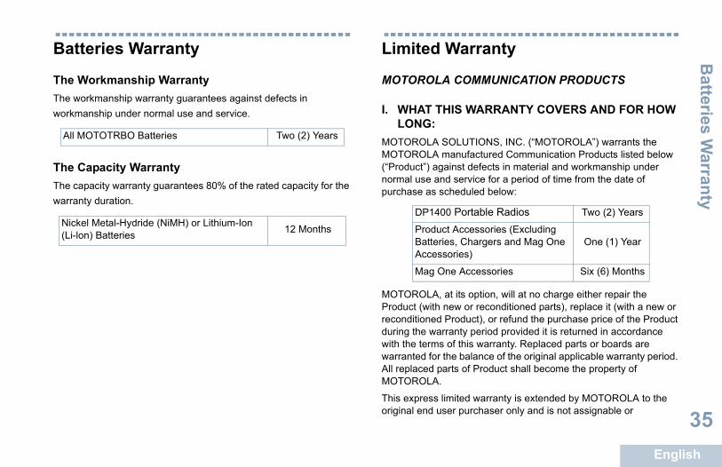
00 Portable Radios Two (2) Years
uct Accessories (Excluding ries, Chargers and Mag One ssories)
One (1) Year
One Accessories Six (6) Months
DP1400_EMEA.book Page 35 Monday, December 15, 2014 3:25 PM
Batteries Warranty
The Workmanship Warranty The workmanship warranty guarantees against defects in workmanship under normal use and service.
The Capacity WarrantyThe capacity warranty guarantees 80% of the rated capacity for the warranty duration.
Limited
MOTOROL
I. WHAT TLONG:
MOTOROLAMOTOROLA(“Product”) anormal use apurchase as
MOTOROLAProduct (withreconditioneduring the wwith the termwarranted foAll replaced MOTOROLA
This expressoriginal end
All MOTOTRBO Batteries Two (2) Years
Nickel Metal-Hydride (NiMH) or Lithium-Ion (Li-lon) Batteries 12 Months
DP14
ProdBatteAcce
Mag
E
36
transferable to any other party. This is the complete warranty for the CONSEQUENTIAL DAMAGES ARISING OUT OF THE USE OR USE SUCH PRODUCT, TO THE FULL EXTENT DISCLAIMED BY LAW.
W RIGHTS: DO NOT ALLOW THE EXCLUSION OR
F INCIDENTAL OR CONSEQUENTIAL DAMAGES N ON HOW LONG AN IMPLIED WARRANTY E ABOVE LIMITATION OR EXCLUSIONS MAY
ives specific legal rights, and there may be other y vary from state to state.
GET WARRANTY SERVICE:de proof of purchase (bearing the date of purchase m serial number) in order to receive warranty o, deliver or send the Product item, transportation
prepaid, to an authorized warranty service location. e will be provided by MOTOROLA through one of its
ranty service locations. If you first contact the sold you the Product (e.g., dealer or service provider), it can facilitate your obtaining e.
IS WARRANTY DOES NOT COVER:amage resulting from use of the Product in other al and customary manner.
DP1400_EMEA.book Page 36 Monday, December 15, 2014 3:25 PM
Lim
ited
War
rant
y
nglish
Product manufactured by MOTOROLA. MOTOROLA assumes no obligations or liability for additions or modifications to this warranty unless made in writing and signed by an officer of MOTOROLA.
Unless made in a separate agreement between MOTOROLA and the original end user purchaser, MOTOROLA does not warrant the installation, maintenance or service of the Product.
MOTOROLA cannot be responsible in any way for any ancillary equipment not furnished by MOTOROLA which is attached to or used in connection with the Product, or for operation of the Product with any ancillary equipment, and all such equipment is expressly excluded from this warranty. Because each system which may use the Product is unique, MOTOROLA disclaims liability for range, coverage, or operation of the system as a whole under this warranty.
II. GENERAL PROVISIONS:This warranty sets forth the full extent of MOTOROLA'S responsibilities regarding the Product. Repair, replacement or refund of the purchase price, at MOTOROLA’s option, is the exclusive remedy. THIS WARRANTY IS GIVEN IN LIEU OF ALL OTHER EXPRESS WARRANTIES. IMPLIED WARRANTIES, INCLUDING WITHOUT LIMITATION, IMPLIED WARRANTIES OF MERCHANTABILITY AND FITNESS FOR A PARTICULAR PURPOSE, ARE LIMITED TO THE DURATION OF THIS LIMITED WARRANTY. IN NO EVENT SHALL MOTOROLA BE LIABLE FOR DAMAGES IN EXCESS OF THE PURCHASE PRICE OF THE PRODUCT, FOR ANY LOSS OF USE, LOSS OF TIME, INCONVENIENCE, COMMERCIAL LOSS, LOST PROFITS OR SAVINGS OR OTHER INCIDENTAL, SPECIAL OR
INABILITY TO SUCH MAY BE
III. STATE LASOME STATESLIMITATION OOR LIMITATIOLASTS, SO THNOT APPLY.
This warranty grights which ma
IV. HOW TOYou must proviand Product iteservice and, alsand insurance Warranty servicauthorized warcompany whichcommunicationwarranty servic
V. WHAT THA) Defects or d
than its norm
Limited W
arranty
English
37
T AND SOFTWARE PROVISIONS: will defend, at its own expense, any suit brought nd user purchaser to the extent that it is based on a Product or parts infringe a United States patent, and will pay those costs and damages finally awarded nd user purchaser in any such suit which are o any such claim, but such defense and payments are n the following:ROLA will be notified promptly in writing by such
of any notice of such claim;ROLA will have sole control of the defense of such
ll negotiations for its settlement or compromise; and Product or parts become, or in MOTOROLA’s opinion become, the subject of a claim of infringement of a tes patent, that such purchaser will permit LA, at its option and expense, either to procure for haser the right to continue using the Product or parts or or modify the same so that it becomes non-infringing t such purchaser a credit for the Product or parts as d and accept its return. The depreciation will be an unt per year over the lifetime of the Product or parts as d by MOTOROLA.
will have no liability with respect to any claim of patent which is based upon the combination of the Product or ed hereunder with software, apparatus or devices not MOTOROLA, nor will MOTOROLA have any liability f ancillary equipment or software not furnished by which is attached to or used in connection with the foregoing states the entire liability of MOTOROLA with
DP1400_EMEA.book Page 37 Monday, December 15, 2014 3:25 PM
B) Defects or damage from misuse, accident, water, or neglect.C)Defects or damage from improper testing, operation,
maintenance, installation, alteration, modification, or adjustment.D)Breakage or damage to antennas unless caused directly by
defects in material workmanship.E) A Product subjected to unauthorized Product modifications,
disassembles or repairs (including, without limitation, the addition to the Product of non-MOTOROLA supplied equipment) which adversely affect performance of the Product or interfere with MOTOROLA's normal warranty inspection and testing of the Product to verify any warranty claim.
F) Product which has had the serial number removed or made illegible.
G)Rechargeable batteries if:(1) any of the seals on the battery enclosure of cells are broken or show evidence of tampering.(2) the damage or defect is caused by charging or using the battery in equipment or service other than the Product for which it is specified.
H)Freight costs to the repair depot.I) A Product which, due to illegal or unauthorized alteration of the
software/firmware in the Product, does not function in accordance with MOTOROLA’s published specifications or the FCC certification labeling in effect for the Product at the time the Product was initially distributed from MOTOROLA.
J) Scratches or other cosmetic damage to Product surfaces that does not affect the operation of the Product.
K) Normal and customary wear and tear.
VI. PATENMOTOROLAagainst the eclaim that theMOTOROLAagainst the eattributable tconditioned oA) that MOTO
purchaserB) that MOTO
suit and aC)should the
be likely toUnited StaMOTOROsuch purcto replaceor to grandepreciateequal amoestablishe
MOTOROLAinfringementparts furnishfurnished byfor the use oMOTOROLAProduct. The
E
38
respect to infringement of patents by the Product or any parts
DP1400_EMEA.book Page 38 Monday, December 15, 2014 3:25 PM
Lim
ited
War
rant
y
nglish
thereof.
Laws in the United States and other countries preserve for MOTOROLA certain exclusive rights for copyrighted MOTOROLA software such as the exclusive rights to reproduce in copies and distribute copies of such MOTOROLA software. MOTOROLA software may be used in only the Product in which the software was originally embodied and such software in such Product may not be replaced, copied, distributed, modified in any way, or used to produce any derivative thereof. No other use including, without limitation, alteration, modification, reproduction, distribution, or reverse engineering of such MOTOROLA software or exercise of rights in such MOTOROLA software is permitted. No license is granted by implication, estoppel or otherwise under MOTOROLA patent rights or copyrights.
VII. GOVERNING LAW:This Warranty is governed by the laws of the State of Illinois, U.S.A.
BackCover_HalfLetter_P299C.fm Page 2 Monday, December 1, 2014 11:48 AM
Motorola Solutions, Inc.
MOTOROLA, MOTO, MOTOROLA SOLUTIONS and the Stylized M logo are trademarks or registered trademarks of Motorola Trademark Holdings, LLC and are used under license.All other trademarks are the property of their respective owners. © 2013, 2014 Motorola Solutions, Inc. All rights reserved.December 2014.
www.motorolasolutions.com/mototrbo
*68012008075*68012008075-BA