non-elliptical resonators part i
TRANSCRIPT

A. Facco
INFN/LNL and FRIB/MSU
SRF2015 – Whistler, BC, Canada
Tutorial n.7
Non-Elliptical Resonators
Part I
2 A. Facco – INFN and MSU Non-Elliptical Resonators-Tutorial at SRF15 September 11-12, 2015 (slide )
Preface
• This is a tutorial. Its aim is not to be fully exhaustive and
rigorous in all aspects, but to transmit key points and
fundamental concepts in the field. The material is presented
in a way that should be understandable without difficulties
by physicists, engineers and also students in these
disciplines who are beginners in SRF.
• This presentation includes material taken from many
sources, and also from previous SRF tutorials which
contain additional information and points of view in some
specific parts. Their reading, having in mind that technology
evolves with time, is recommended too (especially of the
last ones: Delayen 2011, Kelly 2013)
3 A. Facco – INFN and MSU Non-Elliptical Resonators-Tutorial at SRF15 September 11-12, 2015 (slide )
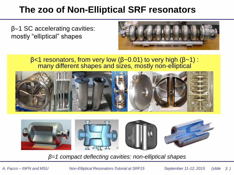
The zoo of Non-Elliptical SRF resonators
β1 SC accelerating cavities:
mostly “elliptical” shapes
β<1 resonators, from very low (β~0.01) to very high (β~1) : many different shapes and sizes, mostly non-elliptical
β=1 compact deflecting cavities: non-elliptical shapes
4 A. Facco – INFN and MSU Non-Elliptical Resonators-Tutorial at SRF15 September 11-12, 2015 (slide )
How did we get there?
Some history

5 A. Facco – INFN and MSU Non-Elliptical Resonators-Tutorial at SRF15 September 11-12, 2015 (slide )
The first low- SC cavities application
•Low beam current: all rf power in
the cavity walls
•2÷3 gap: wide β acceptance for
different ion energies
•Cw operation
Tandem-booster system
New problems: very narrow rf bandwidth, mechanical instabilities
HI boosters for electrostatic accelerators: first and ideal
application of SC technology, hardly achievable NC cavities

6 A. Facco – INFN and MSU Non-Elliptical Resonators-Tutorial at SRF15 September 11-12, 2015 (slide )
Early resonators: 70’s pioneers
Low-β cavities for ion boosters
developed in the 70’s
•β~0.1
•Materials:
•Bulk Nb
•Pb plated Cu
•Ea typically 2 MV/m
•Mechanical stability problems solved
by the first electronic fast tuners for
Helix resonators
7 A. Facco – INFN and MSU Non-Elliptical Resonators-Tutorial at SRF15 September 11-12, 2015 (slide )
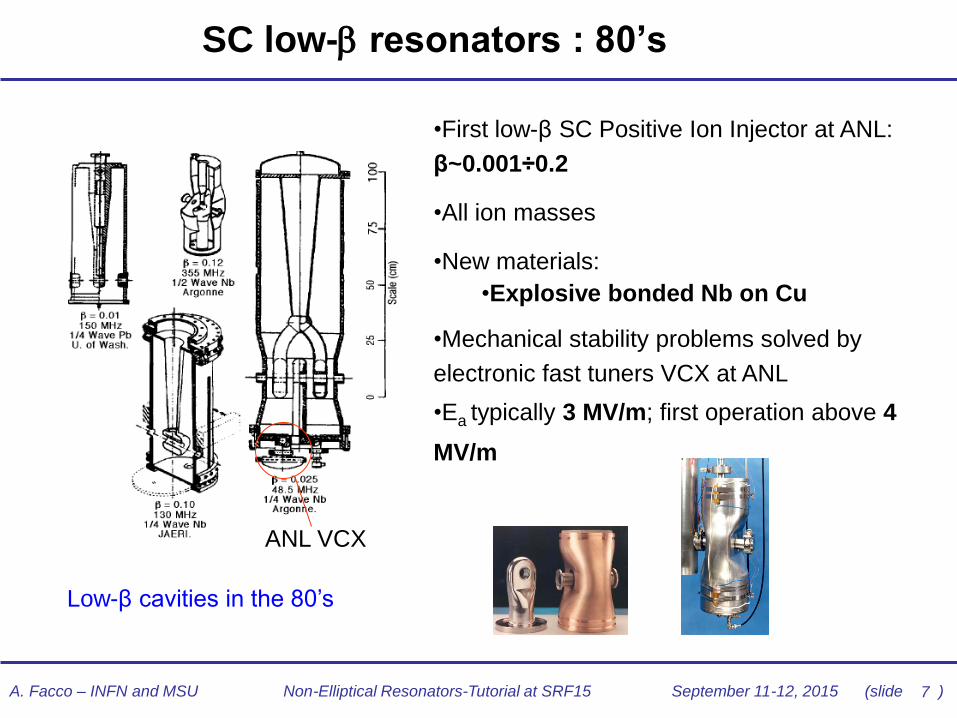
SC low- resonators : 80’s
Low-β cavities in the 80’s
•First low-β SC Positive Ion Injector at ANL:
β~0.001÷0.2
•All ion masses
•New materials:
•Explosive bonded Nb on Cu
•Mechanical stability problems solved by
electronic fast tuners VCX at ANL
•Ea typically 3 MV/m; first operation above 4
MV/m
ANL VCX
8 A. Facco – INFN and MSU Non-Elliptical Resonators-Tutorial at SRF15 September 11-12, 2015 (slide )
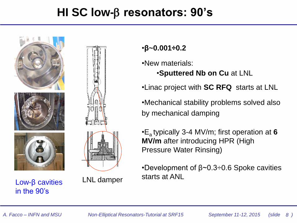
HI SC low- resonators: 90’s
Low-β cavities
in the 90’s
•β~0.001÷0.2
•New materials:
•Sputtered Nb on Cu at LNL
•Linac project with SC RFQ starts at LNL
•Mechanical stability problems solved also
by mechanical damping
•Ea typically 3-4 MV/m; first operation at 6
MV/m after introducing HPR (High
Pressure Water Rinsing)
•Development of β~0.3÷0.6 Spoke cavities
starts at ANL LNL damper

9 A. Facco – INFN and MSU Non-Elliptical Resonators-Tutorial at SRF15 September 11-12, 2015 (slide )
P,D and HI SC low- resonators: the millennials
•~0.001 0.8
•material: mainly Bulk Nb, but also sputtered
•Electropolishing (EP) adopted as standard
surface treatment for low- cavities at ANL
•First high intensity SC low- linacs started
construction
•Development for RIB facilities, neutron
spallation sources, Accelerator Driven
Systems…
•Design Ea typically 6 8 MV/m, up to 15 for
multicell elliptical resonators
2-gap spoke cavity and cryomodule (IPNO)
QWR, HWR and Spoke cavities (ANL)
SNS cryomodule (JLab) –
Elliptical <1
10 A. Facco – INFN and MSU Non-Elliptical Resonators-Tutorial at SRF15 September 11-12, 2015 (slide )
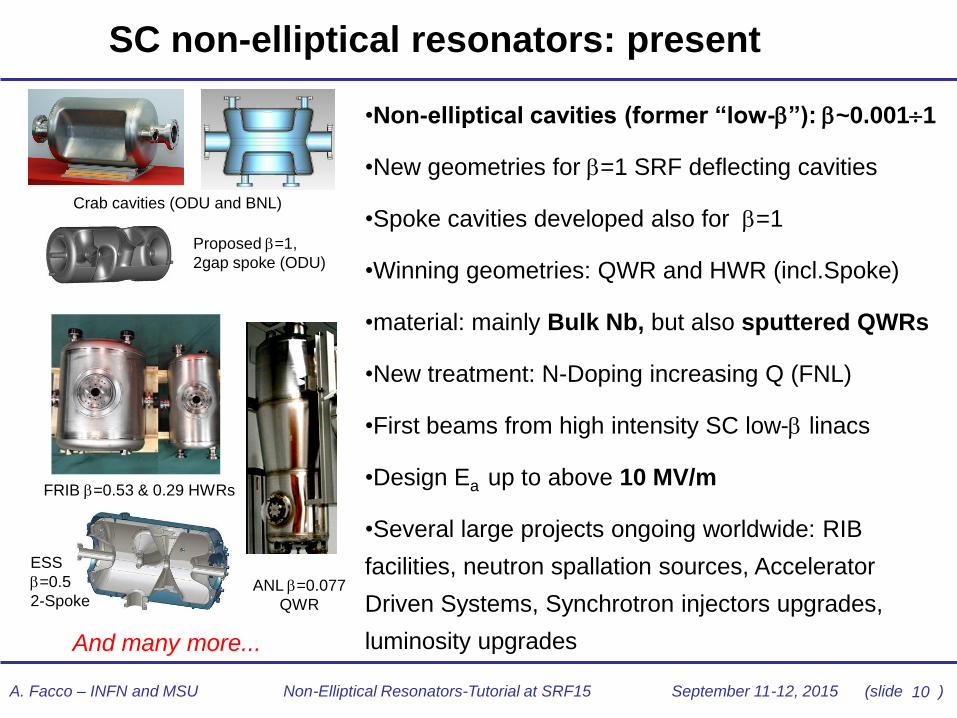
SC non-elliptical resonators: present
•Non-elliptical cavities (former “low-”): ~0.0011
•New geometries for =1 SRF deflecting cavities
•Spoke cavities developed also for =1
•Winning geometries: QWR and HWR (incl.Spoke)
•material: mainly Bulk Nb, but also sputtered QWRs
•New treatment: N-Doping increasing Q (FNL)
•First beams from high intensity SC low- linacs
•Design Ea up to above 10 MV/m
•Several large projects ongoing worldwide: RIB
facilities, neutron spallation sources, Accelerator
Driven Systems, Synchrotron injectors upgrades,
luminosity upgrades
Proposed =1,
2gap spoke (ODU)
FRIB =0.53 & 0.29 HWRs
Crab cavities (ODU and BNL)
ANL =0.077
QWR
ESS
=0.5
2-Spoke
And many more...
11 A. Facco – INFN and MSU Non-Elliptical Resonators-Tutorial at SRF15 September 11-12, 2015 (slide )
Basic principles of TM and TEM cavities

12 A. Facco – INFN and MSU Non-Elliptical Resonators-Tutorial at SRF15 September 11-12, 2015 (slide )
TM mode cavities – Symmetric around beam axis
• TM01 (Transverse Magnetic) mode
• B perpendicular to the EM wave propagation axis
(and to the beam axis)
• On the beam axis B=0, Ez is maximum: ideal for
particle acceleration
BB
pillbox cavities (Normal-Conducting)
NC “nose” and SC “reentrant”
Short gap for low- beams
Elliptical SC cavity working in mode
See tutorial “RF principles and TM mode cavity”

13 A. Facco – INFN and MSU Non-Elliptical Resonators-Tutorial at SRF15 September 11-12, 2015 (slide )
TEM mode cavities
• Only waveguides with 2 conductors and homogeneous cross
section can have pure TEM modes: any change in cross section
introduces longitudinal components
• Traditionally (maybe not fully correctly) we call TEM structures also
the non homogeneous ones which result from modifications of
standard TEM structures (e.g.: tapered coaxial lines)
• Practical “TEM” cavities are not pure TEM: the field is shaped to
build the needed components in the right place for the beam
• TEM (Transverse Electro Magnetic) mode (related to the cavity symmetry axis)
• B and E are perpendicular to the EM wave propagation axis
• The beam axis is perpendicular to the wave propagation axis
TEM propagating wave in a coaxial line TEM cavity example: QWR
14 A. Facco – INFN and MSU Non-Elliptical Resonators-Tutorial at SRF15 September 11-12, 2015 (slide )
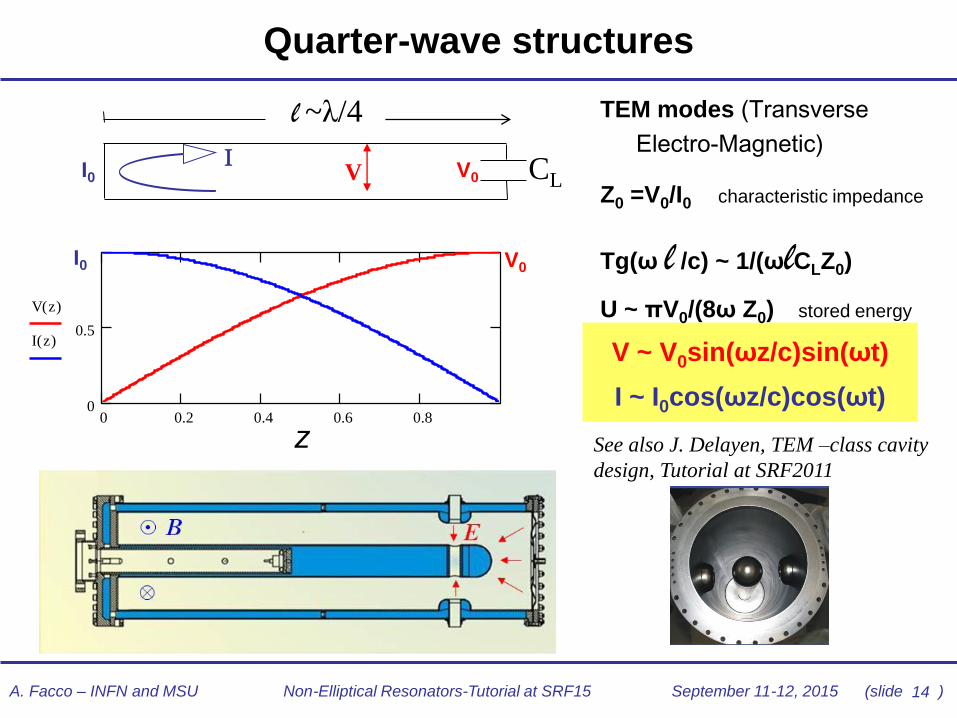
Quarter-wave structures
V ~ V0sin(ωz/c)sin(ωt)
I ~ I0cos(ωz/c)cos(ωt)
TEM modes (Transverse
Electro-Magnetic)
Z0 =V0/I0 characteristic impedance
Tg(ω l /c) ~ 1/(ωlCLZ0)
U ~ πV0/(8ω Z0) stored energy
CL
l ~λ/4
I V V0 I0
0 0.2 0.4 0.6 0.80
0.5
1
V z( )
I z( )
z( )
V0 I0
z
See also J. Delayen, TEM –class cavity
design, Tutorial at SRF2011

15 A. Facco – INFN and MSU Non-Elliptical Resonators-Tutorial at SRF15 September 11-12, 2015 (slide )
Half-wave structures
0 0.5 1 1.5 21
0
1
V z( )
I z( )
z( )~λ/2
CL
U ~ 2πV02/(8ω Z0)
PHWR ~2 PQWR
• A half-wave resonator is equivalent to 2
QWRs facing each other and connected
• The same accelerating voltage is
obtained with about 2 times larger power
I I V0
16 A. Facco – INFN and MSU Non-Elliptical Resonators-Tutorial at SRF15 September 11-12, 2015 (slide )
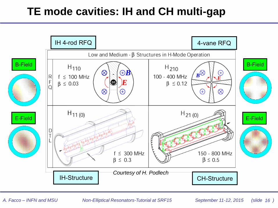
TE mode cavities: IH and CH multi-gap
IH-Structure
4-vane RFQ IH 4-rod RFQ
CH-Structure
E-Field
B-Field B-Field
E-Field
Courtesy of H. Podlech
B
E E
B

17 A. Facco – INFN and MSU Non-Elliptical Resonators-Tutorial at SRF15 September 11-12, 2015 (slide )
Half-wave structures – spoke and multi-spoke
• Spoke can be still considered “TEM-like” HW cavities
with respect to the spoke axis
• Multi-spoke have a similar TEM-like mode when each
cell is considered individually, however some of them
are closer to CH cavities
mode
stabilizing
ridge
18 A. Facco – INFN and MSU Non-Elliptical Resonators-Tutorial at SRF15 September 11-12, 2015 (slide )
Characteristic parameters

19 A. Facco – INFN and MSU Non-Elliptical Resonators-Tutorial at SRF15 September 11-12, 2015 (slide )
Important parameters in accelerating cavities
Avg. accelerating field Ea=VgT(β0)/L MV/m
Stored energy U/ Ea2 J/(MV/m)2
Shunt impedance per meter Rsh=Ea2L/P MΩ/m
Quality Factor Q=ωU/P
Geometrical factor Γ = Q Rs Ω
Peak electric field Ep/Ea
Peak magnetic field Bp/Ea mT/(MV/m)
Optimum β β0
Cavity length L m
where:
Rs=surface resistance of the cavity walls
P =rf power losses in the cavity, proportional to Rs
consta
nts
20 A. Facco – INFN and MSU Non-Elliptical Resonators-Tutorial at SRF15 September 11-12, 2015 (slide )
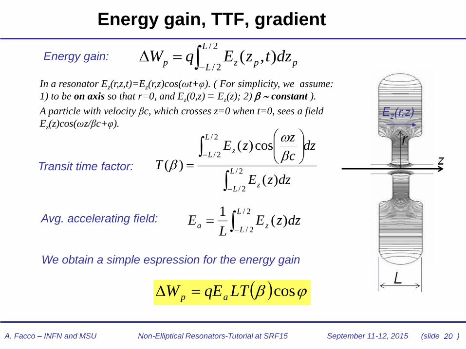
Energy gain, TTF, gradient
Energy gain:
In a resonator Ez(r,z,t)=Ez(r,z)cos(ωt+φ). ( For simplicity, we assume:
1) to be on axis so that r=0, and Ez(0,z) ≡ Ez(z); 2) constant ).
A particle with velocity βc, which crosses z=0 when t=0, sees a field
Ez(z)cos(ωz/βc+φ).
Transit time factor:
We obtain a simple espression for the energy gain
Avg. accelerating field:
cosLTqEW ap =
=2/
2/
2/
2/
)(
cos)(
)(L
Lz
L
Lz
dzzE
dzc
zzE
T
=
2/
2/)(
1 L
Lza dzzE
LE
=
2/
2/),(
L
Lppzp dztzEqW

21 A. Facco – INFN and MSU Non-Elliptical Resonators-Tutorial at SRF15 September 11-12, 2015 (slide )
Remark: different definitions of gradient Ea
1.00E+07
1.00E+08
1.00E+09
1.00E+10
0 1 2 3 4 5 6 7 8 9 10 11 12 13 14 15 16 17 18 19 20
Ea (MV/m)
Q
Z16 PIAVE
Z4 ALPI
Z16 PIAVE ANL DEF.
• In QWR and HWRs it is difficult to define L: lint , Lmax or even nβλ/2
• The shorter L is defined, the larger Ea appears in Q vs. Ea graphs
• The energy gain, however, is always the same and all definitions are consistent
• Nowadays most popular: Leff= nβλ/2
lint Lmax
Blue diamonds and red triangles:
same curve, different definition
Lmax
lint
nβλ/2
(n = N. of gaps)
22 A. Facco – INFN and MSU Non-Elliptical Resonators-Tutorial at SRF15 September 11-12, 2015 (slide )
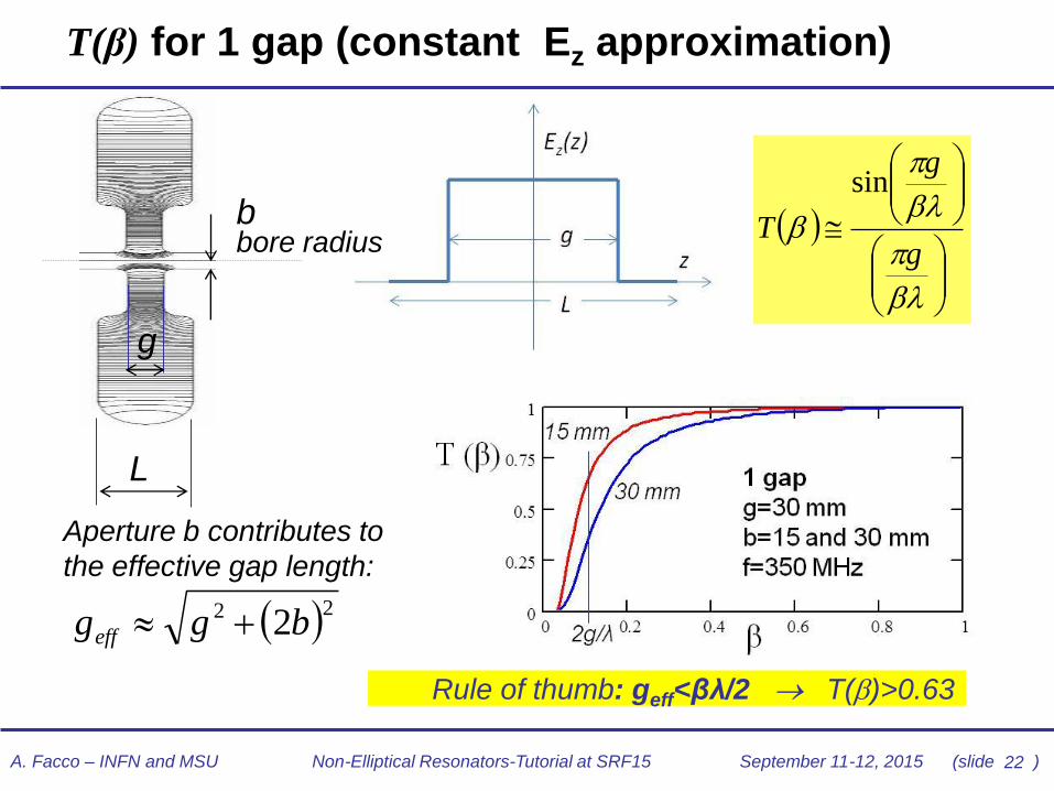
T(β) for 1 gap (constant Ez approximation)
L
g
b bore radius
Aperture b contributes to
the effective gap length:
22 2bggeff
g
g
T
sin
Rule of thumb: geff<βλ/2 T()>0.63

23 A. Facco – INFN and MSU Non-Elliptical Resonators-Tutorial at SRF15 September 11-12, 2015 (slide )
In summary, to combine:
• low of the beam,
• large aperture for good beam transmission,
• reasonably long gap for sufficient energy gain, and
• geff<βλ/2 for high transit time factor,
we need large λ, thus low frequency.
TM elliptical cavities transverse size
• prohibitively large at low frequency
TEM resonators size: /2 and /4
• suitable for low frequency and thus for low-
Limitation of TM mode cavities for low beta

24 A. Facco – INFN and MSU Non-Elliptical Resonators-Tutorial at SRF15 September 11-12, 2015 (slide )
T(β) for 2 gap (π mode)
resultingTTF curve
(For more than 2 equal gaps in π
mode, only the 2° term changes)
(constant Ez approximation)
L
lint
L
lint
g
d
L
lint
L
lint
g
d
Ez Ez
L
lint
L
lint
g
d
L
lint
L
lint
g
d
Ez Ez
0.2 0.4 0.6 0.80.5
0
0.5
1
β
T(β)
dg
g
T sin
sin
1-gap term, high if g<βλ/2
2 gap term, high if d~βλ/2
See also J. Delayen, TEM –class cavity design, Tutorial at SRF2011
25 A. Facco – INFN and MSU Non-Elliptical Resonators-Tutorial at SRF15 September 11-12, 2015 (slide )
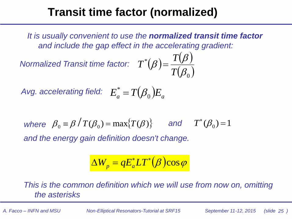
Transit time factor (normalized)
It is usually convenient to use the normalized transit time factor
and include the gap effect in the accelerating gradient:
Normalized Transit time factor:
Avg. accelerating field:
where
and the energy gain definition doesn't change.
This is the common definition which we will use from now on, omitting
the asterisks
)(max)( 00 / TT = and
1)( 0 = T
cos= LTqEW ap
aa ETE 0
* =
0
*
T
TT =

26 A. Facco – INFN and MSU Non-Elliptical Resonators-Tutorial at SRF15 September 11-12, 2015 (slide )
Transit time factor curves vs. gap number n
0.5 1 1.5 20
0.25
0.5
0.75
1
T2 0.001 0.001 d ( )
T3 0.001 0.001 d ( )
T4 0.001 0.001 d ( )
T5 0.001 0.001 d ( )
0
3 gap
2 gap
4 gap
5 gap
T (β)
β/β0
• the larger the gap n., the larger the energy gain at a given gap voltage Vg
• BUT the larger the gap n., the narrower the velocity acceptance
constant calls for large n
fast varying calls for small n
Normalized transit time factor curves vs. normalized
velocity, for cavities with different number of gap
27 A. Facco – INFN and MSU Non-Elliptical Resonators-Tutorial at SRF15 September 11-12, 2015 (slide )
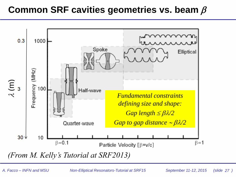
Common SRF cavities geometries vs. beam
(From M. Kelly’s Tutorial at SRF2013)
Fundamental constraints
defining size and shape:
Gap length /2
Gap to gap distance /2
(
m)

28 A. Facco – INFN and MSU Non-Elliptical Resonators-Tutorial at SRF15 September 11-12, 2015 (slide )
Non-elliptical SRF cavities main applications
Type max Beam (A/q) Max current
HI linacs for nuclear physics
research ~ 0.2 (0.5) Ions (7 66) 1 A
HI drivers for RIB facilities and ADS ~ 0.30.9 Ions (~ 110) ~0.130 mA
p,d linacs for radioisotope
production ~ 0.3 p, d (1 2) ~110 mA
Proton Accelerators for neutron
spallation sources ~ 1 p (1)
~10100 mA
pulsed
Deuteron Accelerators for
material irradiation ~ 0.3 d (2) 100 mA cw
High- linacs with size
limitations (proposed) 1 e 1 mA
~ 1 deflecting and crabbing 1 e, p(1) ~1 A
29 A. Facco – INFN and MSU Non-Elliptical Resonators-Tutorial at SRF15 September 11-12, 2015 (slide )
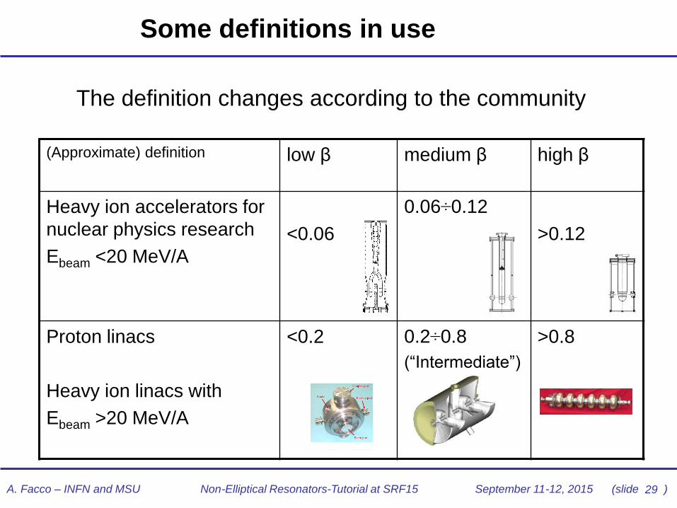
Some definitions in use
(Approximate) definition low β medium β high β
Heavy ion accelerators for
nuclear physics research
Ebeam <20 MeV/A
<0.06
0.06÷0.12
>0.12
Proton linacs
Heavy ion linacs with
Ebeam >20 MeV/A
<0.2 0.2÷0.8
(“Intermediate”)
>0.8
The definition changes according to the community
Superconducting QWR family
=0.045, 0.082, 0.11, 0.22
f=80,120,160,320 MHz

30 A. Facco – INFN and MSU Non-Elliptical Resonators-Tutorial at SRF15 September 11-12, 2015 (slide )
Typical superconducting low-β linacs
• many short cavities
• independently powered
• large aperture
• different beam velocity profiles
• different particle q/A
• cavity fault tolerance

31 A. Facco – INFN and MSU Non-Elliptical Resonators-Tutorial at SRF15 September 11-12, 2015 (slide )
Cavity design

32 A. Facco – INFN and MSU Non-Elliptical Resonators-Tutorial at SRF15 September 11-12, 2015 (slide )
What is a good SC low-β resonator?
A good resonator must fulfill the following principal
(rather general) requirements:
1. Large energy gain
2. Low power dissipation
3. Easy and reliable operation for a long time
4. Easy installation and maintenance
5. Low cost-to-performance ratio

33 A. Facco – INFN and MSU Non-Elliptical Resonators-Tutorial at SRF15 September 11-12, 2015 (slide )
Preliminary choices
• beam energy → β0, gap length
• velocity acceptance → n. of gaps
• beam size, transv. → bore radius
• beam long. size & f → rf frequency
• beam power → rf coupling type
• gradient, efficiency → geometry
• cw, pulsed → mech. design
• cost, reliability → technology
• …
beam
specific
atio
ns
technolo
gic
al
choic
es

A. Facco – INFN and MSU Non-Elliptical Resonators-Tutorial at SRF15 September 11-12, 2015 (slide )
• Maximum peak fields, electric Ep and magnetic Bp
• achieved (cw) 90 MV/m and 150 mT
• reliable specs 40 MV/m and 75 mT (depending on your “bravery
factor”)
• RBCS •
• Rres residual resistance= Rs- RBCS • Achievable <1 nΩ
• reliable specs <10 n Ω
• Rf power density on the cavity walls • Achievable 1W/cm2 at 4.2K; 5.6 W/cm2 at 2K
• Reliable: much below (related also to cooling system)
• Critical Temperature vs. magnetic field • .
Some useful numbers and rules of thumb to have in mind
200/12.9 BTc =
34
𝑅𝐵𝐶𝑆 𝑂ℎ𝑚 = 2 × 10⁻⁴ 1
𝑇 𝑓(𝐺𝐻𝑧)
1.5
2
𝑒𝑥𝑝 −17.67
𝑇

2K or 4.2K?
• Rs= RBCS(T,f)+Rresidual
• RBCS increases with f 2
• 2K is more expensive than 4.2K: it
appears convenient only if RBCS
(4.2) > Rresidual
• Nowadays reliable Rres is below
10n: so the (blurry) border seems
to be around 200 MHz
• However:
– 2K systems provide better He
pressure stability
– 2K allows higher gradients than 4.2K
– Large linacs often need a 2K system
for high- cavities anyhow
35
10 100 1 103
1 104
1 104
0.01
1
100
1 104
f (MHz)
Rs
(no
hm
)
Rbcs f 2 ( )
Rbcs f 4.2 ( )
f
f (MHz) 80 160 320 640 1280
Rs(4.2K) 2.02 8.07 32.3 129 516
Rs(2K) 0.04 0.17 0.67 2.7 10.6
BCS surface resistance vs. frequency
in Nb, at 2 and 4.2K (nohm)
A. Facco – INFN and MSU Non-Elliptical Resonators-Tutorial at SRF15 September 11-12, 2015 (slide )
After overall optimization, 2K systems can be the best choice
also for low frequency cavities, especially in large linacs

36 A. Facco – INFN and MSU Non-Elliptical Resonators-Tutorial at SRF15 September 11-12, 2015 (slide )
Electromagnetic design
37 A. Facco – INFN and MSU Non-Elliptical Resonators-Tutorial at SRF15 September 11-12, 2015 (slide )
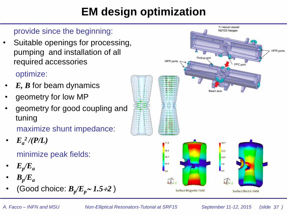
EM design optimization
minimize peak fields:
• Ep/Ea
• Bp/Ea
• (Good choice: Bp/Ep 1.52 )
maximize shunt impedance:
• Ea2 /(P/L)
optimize:
• E, B for beam dynamics
• geometry for low MP
• geometry for good coupling and
tuning
provide since the beginning:
• Suitable openings for processing,
pumping and installation of all
required accessories

38 A. Facco – INFN and MSU Non-Elliptical Resonators-Tutorial at SRF15 September 11-12, 2015 (slide )
Remark on overall geometry optimization
• Have in mind the overall
scope when optimizing
• Optimization of the
cavity influences
complexity and cost
• Shape refinements
should be pursued as
far as needed by
accelerator and beam
dynamics requirements
45% Larger OD and ID to obtain
45% Lower Bp/Ea
Larger r for
15% Lower Ep/Ea
Larger volume for
Higher Rsh/Q
Cost effective geometry,
optimized for a large
linac section operating
at intermediate gradient
(Bp/Ep 2)
Same , more
complex geometry,
optimized for
operation at highest
gradient (Bp/Ep 1.5) See also M. Kelly, TEM –class
cavity design, Tutorial at SRF2013

39 A. Facco – INFN and MSU Non-Elliptical Resonators-Tutorial at SRF15 September 11-12, 2015 (slide )
EM design: hints on Rf losses
Ptop=0.286 W
Poutcond=1.009 W
Pincond=3.040 WPbport=0.004 W
Psphere=0.001 W
Pbottom=0.0001 W
f=106 MHz
Ea=6 MV/m
RsNb=38 n
P=4.345 W
HFSS Model SC QWR for o =0.075
Magnetic field distribution
and calculated power dissipation
Ptop=0.286 W
Poutcond=1.009 W
Pincond=3.040 WPbport=0.004 W
Psphere=0.001 W
Pbottom=0.0001 W
f=106 MHz
Ea=6 MV/m
RsNb=38 n
P=4.345 W
HFSS Model SC QWR for o =0.075
Magnetic field distribution
and calculated power dissipation
(Courtesy of V. Zvyagintsev)
• Keep maximum rf
losses well below ~1
W/cm2 at 4.2 K and
~5.6 W/cm2 at 2K
• Large safety margin
required: local defects
can increase power
losses significantly

40 A. Facco – INFN and MSU Non-Elliptical Resonators-Tutorial at SRF15 September 11-12, 2015 (slide )
EM design: Multipacting
• Multipacting: resonant field emission of electrons under the action of the EM field
• 3 simultaneous conditions to start MP: 1. stable trajectories ending on cavity walls (cavity geometry) +
2. secondary emission coefficient >1 (surface preparation) +
3. initial electron impinging the right surface at the right field and phase to start the process (vacuum, presence of free electrons)
• Initial electrons can be originated and captured far from the resonant trajectory (cavity geometry)
MP region

41 A. Facco – INFN and MSU Non-Elliptical Resonators-Tutorial at SRF15 September 11-12, 2015 (slide )
Multipacting in low-β cavities - examples
Courtesy of ACCEL
1 wall MP
“horseshoe”
2-walls MP
2-point MP in a HWR
• 1 wall MP: EB to turn
the trajectory
• 2 walls MP: mainly E
• B can be used to displace
electrons away from the
MP area

42 A. Facco – INFN and MSU Non-Elliptical Resonators-Tutorial at SRF15 September 11-12, 2015 (slide )
Multipacting calculations
• It is common experience that MP could always be
conditioned in a low- cavity, if clean and in a good
vacuum. However, this may take a long time (days).
This is not acceptable when operating an accelerator
• MP can be minimized with an appropriate choice of the
cavity shape
• Several powerful 3D codes are nowadays available for
MP particles tracking. Some are included in packages
for 3D EM and mechanical design of cavities.
• Simulations are very powerful but they might miss some
of the all possible modes

43 A. Facco – INFN and MSU Non-Elliptical Resonators-Tutorial at SRF15 September 11-12, 2015 (slide )
Avoiding multipacting
n. initial file 24020 n. initial file 4840 n. initial file 16516
n. selected file 1578 n. selected file 95 n. selected file 0
ratio 6.60% ratio 2% ratio 0%
range 0-25 MV/m range 0-25 MV/m range 0-25 MV/m
Total Number of runs with TVTRAG 45376
Distribution of point
0
4
8
12
16
20
24
28
0 4 8 12cm
cm
initial
final
Distribution of point
0
4
8
12
16
20
24
28
0 4 8 12
cm
cm
initial
final
Distribution of point
0
4
8
12
16
20
24
28
0 4 8 12
cm
cm
initial
final
Example: simple 350 MHz, 2D geometry
Results:
• A sharp step in the “nose” removed an
accumulation point near the beam gap
which was present in a conical nose
• Ellipsoidal shape 1.5:1 removed all MP
trajectories at the equator
• MP negligible in the final shape (confirmed
by SRF test)
• cavities must be designed with no stable MP trajectories, or with impact
energy out of the δ>1 region
• Accumulation points, which collect electrons from a large volume and
position them in a stable trajectory, should be removed by geometry
• Levels at high Ea are more dangerous than levels at low Ea
• it is often impossible to eliminate levels completely; to make them
tolerable, the volume in which the electrons are captured must be small

44 A. Facco – INFN and MSU Non-Elliptical Resonators-Tutorial at SRF15 September 11-12, 2015 (slide )
3D example: redesigned HWR for MP removal
first design:
0 20 40 6010
20
30
40
cavity wall
multipacting path 1
multipacting path 2
y[m
m]
z[mm]
redesign A:
outer wall
inclined
redesign B:
inner wall
inclined
multipacting at
Epeak=0.1MV/m
no multipacting
no
multipacting
SARAF HWR
(Courtesy of ACCEL)
Accumulation point

45 A. Facco – INFN and MSU Non-Elliptical Resonators-Tutorial at SRF15 September 11-12, 2015 (slide )
Mechanical design
46 A. Facco – INFN and MSU Non-Elliptical Resonators-Tutorial at SRF15 September 11-12, 2015 (slide )
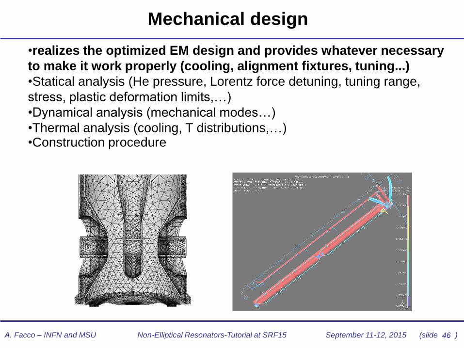
Mechanical design
•realizes the optimized EM design and provides whatever necessary
to make it work properly (cooling, alignment fixtures, tuning...)
•Statical analysis (He pressure, Lorentz force detuning, tuning range,
stress, plastic deformation limits,…)
•Dynamical analysis (mechanical modes…)
•Thermal analysis (cooling, T distributions,…) •Construction procedure

47 A. Facco – INFN and MSU Non-Elliptical Resonators-Tutorial at SRF15 September 11-12, 2015 (slide )
Choice of the SC technology
• Bulk Nb (by far the most used) – highest performance, many
manufacturers, any shape and f
• performance ***** cost **
• Sputtered Nb on Cu (only on QWRs) – good performance, lower cost than bulk
Nb in large production, simple shapes
• performance *** cost ***
• (Plated Pb on Cu - abandoned – lower performance, cheap and affordable
also in a small laboratory
• performance * cost ***** )
See dedicated tutorial “Beyond bulk niobium”
48 A. Facco – INFN and MSU Non-Elliptical Resonators-Tutorial at SRF15 September 11-12, 2015 (slide )
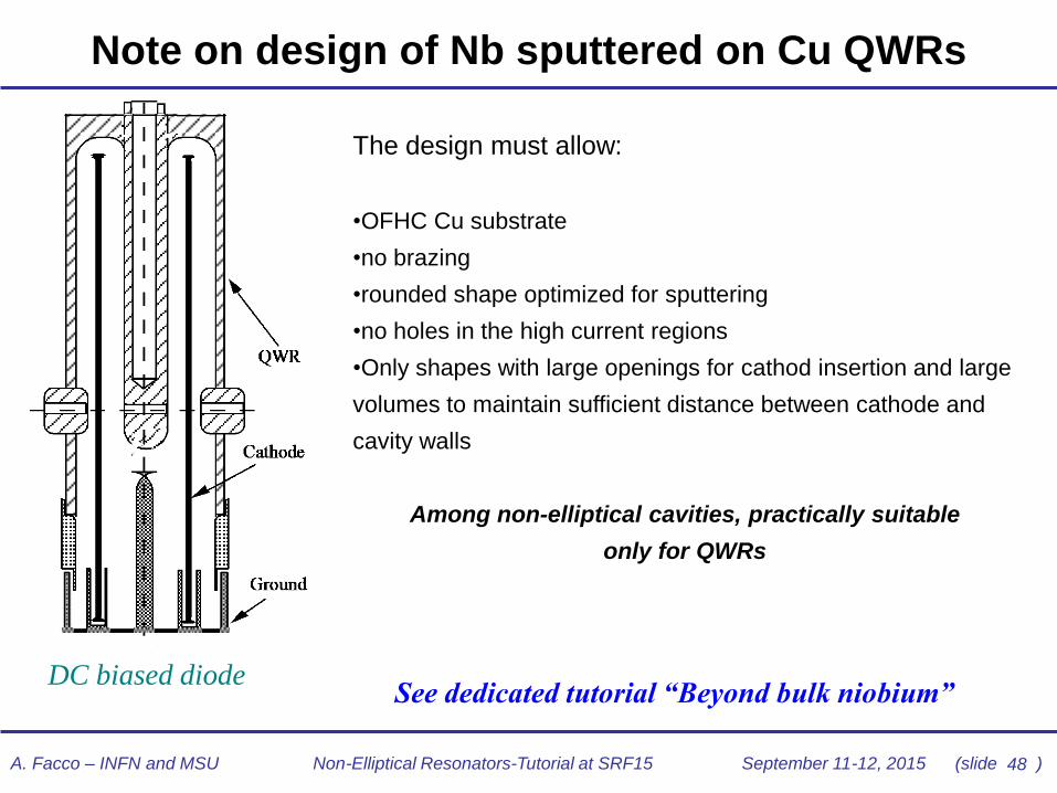
DC biased diode
Note on design of Nb sputtered on Cu QWRs
The design must allow:
•OFHC Cu substrate
•no brazing
•rounded shape optimized for sputtering
•no holes in the high current regions
•Only shapes with large openings for cathod insertion and large
volumes to maintain sufficient distance between cathode and
cavity walls
Among non-elliptical cavities, practically suitable
only for QWRs
See dedicated tutorial “Beyond bulk niobium”

49 A. Facco – INFN and MSU Non-Elliptical Resonators-Tutorial at SRF15 September 11-12, 2015 (slide )
Niobium properties: note on the RRR choice
• Thermal conductivity at 4.2 K:
k = RRR/4 (W/m)/K
• high RRR required, which have higher cost and
poorer mechanical properties compared to
normal grade Nb (RRR~40)
• Nowadays typical good choice for low-β cavities:
RRR250 , almost a standard for Nb vendors
50 A. Facco – INFN and MSU Non-Elliptical Resonators-Tutorial at SRF15 September 11-12, 2015 (slide )
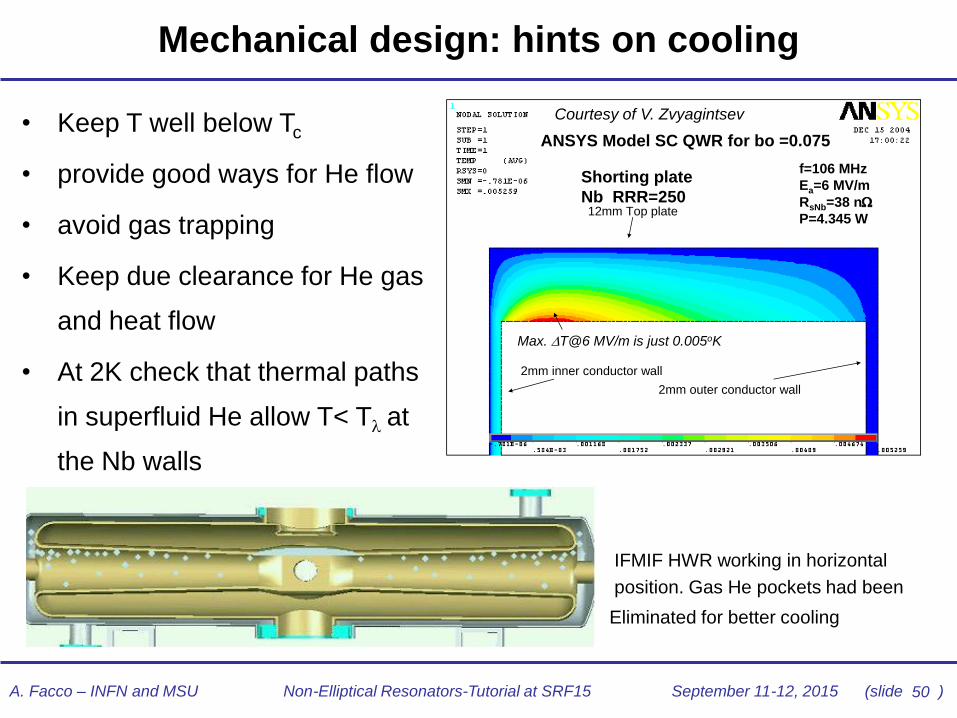
Mechanical design: hints on cooling
12mm Top plate
Shorting plate
Nb RRR=250
2mm inner conductor wall
2mm outer conductor wall
Max. T@6 MV/m is just 0.005oK
f=106 MHz
Ea=6 MV/m
RsNb=38 n
P=4.345 W
ANSYS Model SC QWR for bo =0.075
12mm Top plate
Shorting plate
Nb RRR=250
2mm inner conductor wall
2mm outer conductor wall
Max. T@6 MV/m is just 0.005oK
f=106 MHz
Ea=6 MV/m
RsNb=38 n
P=4.345 W
ANSYS Model SC QWR for bo =0.075
Courtesy of V. Zvyagintsev • Keep T well below Tc
• provide good ways for He flow
• avoid gas trapping
• Keep due clearance for He gas
and heat flow
• At 2K check that thermal paths
in superfluid He allow T< T at
the Nb walls
IFMIF HWR working in horizontal
position. Gas He pockets had been
Eliminated for better cooling

51 A. Facco – INFN and MSU Non-Elliptical Resonators-Tutorial at SRF15 September 11-12, 2015 (slide )
Helium vessel
• Most non-elliptical cavities are built with integrated He vessel, which performs also
structural functions
• Practical materials for He vessels:
• Stainless steel
• cost effective, excellent mechanical properties, TIG weldable in air
• Different thermal contraction from Nb: bellows required
• Not weldable with Nb: transition SS to Nb parts required (explosive bonded,
brazed…)
• Not suitable for HT baking: to be added to the cavity after 800 °C baking
• Titanium
• Excellent mechanical properties, weldable with Nb (EBW), TIG weldable in inert
atmosphere, suitable for HT baking
• Thermal contraction similar to Nb
• Material cost higher than SS
• Nb, NbTi
• Perfect matching and weldability (by EBW) with Nb, good mechanical properties
• Thermal contraction same as Nb, suitable for HT baking
• High cost compared to SS and Ti

52 A. Facco – INFN and MSU Non-Elliptical Resonators-Tutorial at SRF15 September 11-12, 2015 (slide )
Mechanical reinforcement: double wall
The double wall
structure allows to
null the net force
of the He pressure
It is possible to
expose to He
pressure large
surfaces without
making them
collapse
a careful design
can minimize
df/dP

53 A. Facco – INFN and MSU Non-Elliptical Resonators-Tutorial at SRF15 September 11-12, 2015 (slide )
Cavity accessories
54 A. Facco – INFN and MSU Non-Elliptical Resonators-Tutorial at SRF15 September 11-12, 2015 (slide )
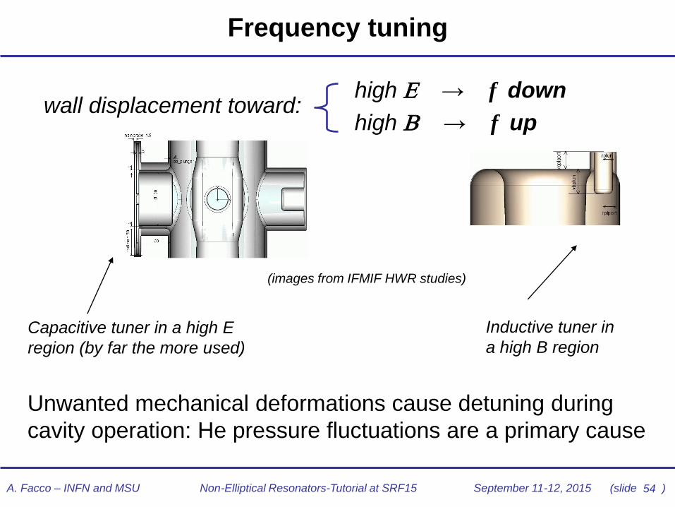
Frequency tuning
Capacitive tuner in a high E
region (by far the more used)
Inductive tuner in
a high B region
high E → f down
high B → f up wall displacement toward:
(images from IFMIF HWR studies)
Unwanted mechanical deformations cause detuning during
cavity operation: He pressure fluctuations are a primary cause
55 A. Facco – INFN and MSU Non-Elliptical Resonators-Tutorial at SRF15 September 11-12, 2015 (slide )
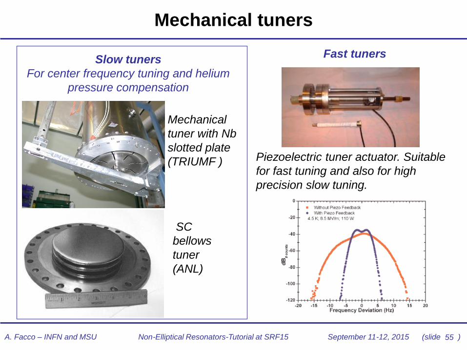
Mechanical tuners
Mechanical
tuner with Nb
slotted plate
(TRIUMF ) Piezoelectric tuner actuator. Suitable
for fast tuning and also for high
precision slow tuning.
Slow tuners
For center frequency tuning and helium
pressure compensation
Fast tuners
SC
bellows
tuner
(ANL)
56 A. Facco – INFN and MSU Non-Elliptical Resonators-Tutorial at SRF15 September 11-12, 2015 (slide )
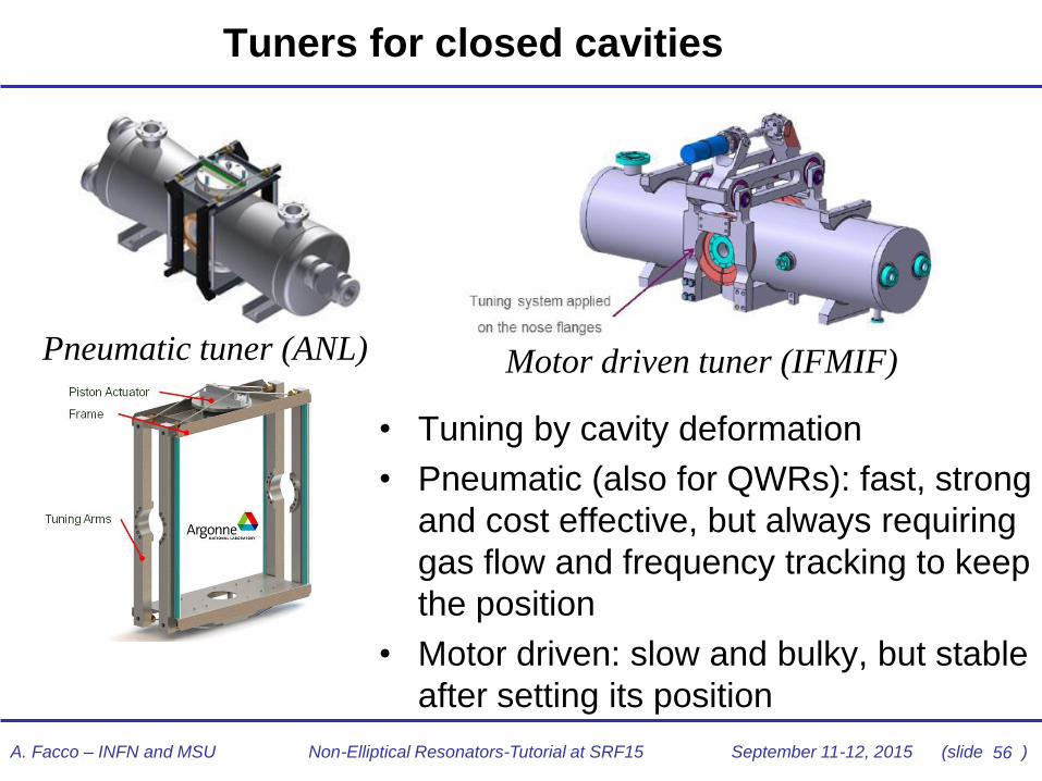
Tuners for closed cavities
• Tuning by cavity deformation
• Pneumatic (also for QWRs): fast, strong
and cost effective, but always requiring
gas flow and frequency tracking to keep
the position
• Motor driven: slow and bulky, but stable
after setting its position
Motor driven tuner (IFMIF) Pneumatic tuner (ANL)
57 A. Facco – INFN and MSU Non-Elliptical Resonators-Tutorial at SRF15 September 11-12, 2015 (slide )
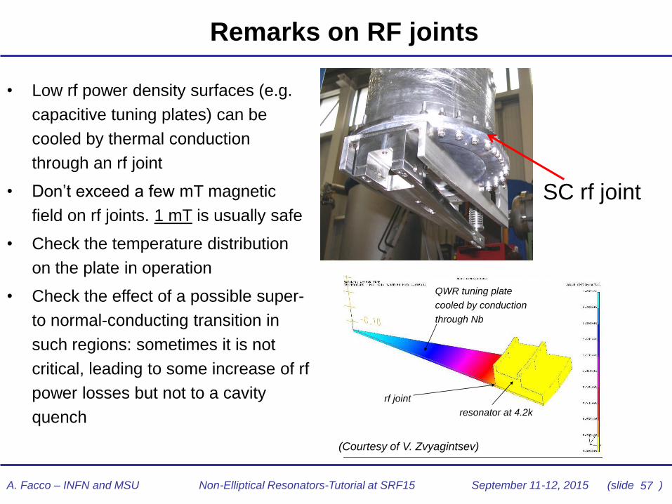
Remarks on RF joints
QWR tuning plate
cooled by conduction
through Nb
resonator at 4.2k
rf joint
(Courtesy of V. Zvyagintsev)
• Low rf power density surfaces (e.g.
capacitive tuning plates) can be
cooled by thermal conduction
through an rf joint
• Don’t exceed a few mT magnetic
field on rf joints. 1 mT is usually safe
• Check the temperature distribution
on the plate in operation
• Check the effect of a possible super-
to normal-conducting transition in
such regions: sometimes it is not
critical, leading to some increase of rf
power losses but not to a cavity
quench
SC rf joint

58 A. Facco – INFN and MSU Non-Elliptical Resonators-Tutorial at SRF15 September 11-12, 2015 (slide )
100 kW power
coupler for 125
mA beam
(IFMIF/EVEDA)
Rf power coupling in TEM cavities
500 W Inductive coupler (TRIUMF)
• Inductive couplers at low P (<1 kW) and low f (<300 MHz)
• Capacitive couplers above ~1 kW and ~ 300 MHz
• High power couplers can be larger than their resonators and require a well
integrated design
20 kW Capacitive coupler (IPNO)
See dedicated tutorial “Fundamental Power couplers and HOM couplers for SC application”
59 A. Facco – INFN and MSU Non-Elliptical Resonators-Tutorial at SRF15 September 11-12, 2015 (slide )
Fabrication, tuning, processing

60 A. Facco – INFN and MSU Non-Elliptical Resonators-Tutorial at SRF15 September 11-12, 2015 (slide )
SRF cavities typical construction steps
•parts obtained by machining and forming of
Nb sheets, rods, plates,…
•Parts joined before welding (“stack-up”), 1st
frequency test and dimensional adjustment
•Cleaned Nb parts joined by electron beam
welding in HV (<10-5 mbar)
•2nd frequency adjustment, He vessel assembly
•surface treatment: chemical polishing,
electropolishing (barrel polishing,…)
•HT baking at 600800 °C, (N doping+EP/CP)
•high pressure water rinsing
•(120 °C baking)
Nowadays several vendors possess all
these technological capabilities and can
deliver “turn-key” the cavities you designed
61 A. Facco – INFN and MSU Non-Elliptical Resonators-Tutorial at SRF15 September 11-12, 2015 (slide )
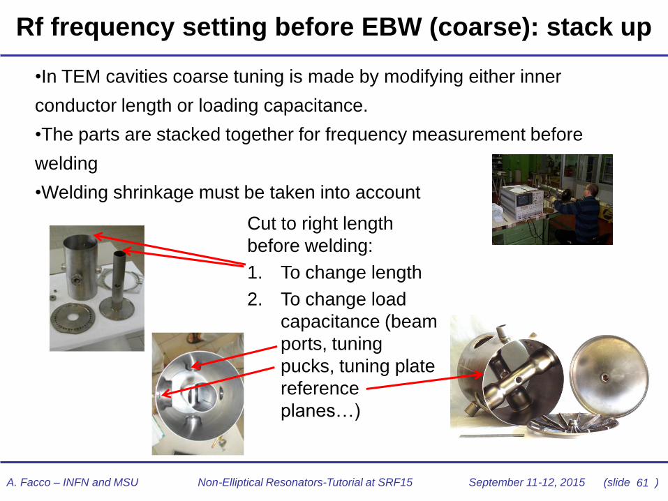
Rf frequency setting before EBW (coarse): stack up
•In TEM cavities coarse tuning is made by modifying either inner
conductor length or loading capacitance.
•The parts are stacked together for frequency measurement before
welding
•Welding shrinkage must be taken into account
Cut to right length
before welding:
1. To change length
2. To change load
capacitance (beam
ports, tuning
pucks, tuning plate
reference
planes…)

62 A. Facco – INFN and MSU Non-Elliptical Resonators-Tutorial at SRF15 September 11-12, 2015 (slide )
Rf frequency correction after welding (coarse)
•After welding tuning operations are more
limited and correction range is smaller
•Some of the main methods:
1. Plastic deformation (usually to
change load capacitance)
2. Puck insertion (QWRs removable
plate): adjusting the puck length it
is easy to adjust the frequency
3. Differential etching: removes
material selectively to increase
length or load capacitance
1. New entry 2015: virtual welding…

63 A. Facco – INFN and MSU Non-Elliptical Resonators-Tutorial at SRF15 September 11-12, 2015 (slide )
Virtual EB and TIG Welding
1. Virtual EBW: applied
not to join two parts,
but only to cause
controlled contraction
of the Nb metal in
strategic positions,
thus obtaining
controlled frequency
shifts. Very precise and
reproducible
2. Virtual TIG: similar
operation on the He
vessel, done in inert
athmosphere
“Virtual” EB welds on Nb
reducing cavity length
(frequency up)
“Virtual” TIG welds
on Ti vessel:
reducing vessel
circumference,
beam ports are
pushed in
(frequency down)
64 A. Facco – INFN and MSU Non-Elliptical Resonators-Tutorial at SRF15 September 11-12, 2015 (slide )
Cavity processing
• Cavity processing is nowadays similar for elliptical and non-elliptical cavities (See
dedicated tutorial “Clean room techniques and cavity preparation”)
• Typical sequence (summary of main steps):
• Electropolishing (EP) and/or Chemical polishing (CP) – to remove 150 m of Nb
and produce a clean and smooth surface of pure Nb
• 600800 °C baking in high vacuum - mostly to eliminate Q-disease
• (N doping during 800 °C baking – to reduce Rs and increase Q. New technique,
not yet implemented in operating linacs but in future ones)
• Light etch (a few m of CP or EP, if needed) – to remove possible contamination
from furnace (or to reach the right depth in Nb after N doping)
• High pressure water rinsing (HPR), clean drying – to remove any residual particle
from the rf surface
• Low T baking 80120 °C baking (if needed) – to outgas and improve vacuum (120
°C baking in addition can reduce RBCS , but it can also increase Rres)
• RF processing in the cryostat: multipacting conditioning, high power rf processing,
Helium processing (if needed)

65 A. Facco – INFN and MSU Non-Elliptical Resonators-Tutorial at SRF15 September 11-12, 2015 (slide )
Operational issues
66 A. Facco – INFN and MSU Non-Elliptical Resonators-Tutorial at SRF15 September 11-12, 2015 (slide )
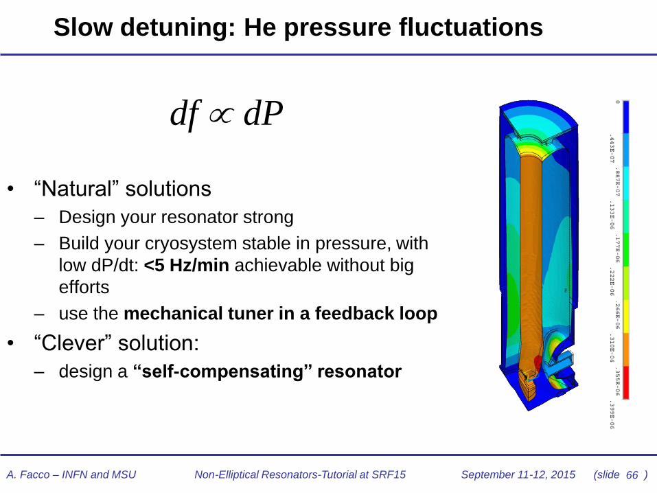
Slow detuning: He pressure fluctuations
df dP
• “Natural” solutions
– Design your resonator strong
– Build your cryosystem stable in pressure, with
low dP/dt: <5 Hz/min achievable without big
efforts
– use the mechanical tuner in a feedback loop
• “Clever” solution:
– design a “self-compensating” resonator
67 A. Facco – INFN and MSU Non-Elliptical Resonators-Tutorial at SRF15 September 11-12, 2015 (slide )
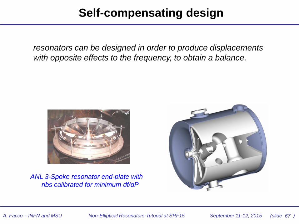
Self-compensating design
resonators can be designed in order to produce displacements
with opposite effects to the frequency, to obtain a balance.
ANL 3-Spoke resonator end-plate with
ribs calibrated for minimum df/dP

68 A. Facco – INFN and MSU Non-Elliptical Resonators-Tutorial at SRF15 September 11-12, 2015 (slide )
Lorentz Force detuning (LFD)
δf -δ(Ea2)
• Lorentz force (radiation pressure) gives a typical
quadratic detuning with field, always down
• solutions: strong mechanical structure, symmetric
design (IC centering), tuning in feedback
Lorenz Force detuning measured in a 80
MHz QWR

69 A. Facco – INFN and MSU Non-Elliptical Resonators-Tutorial at SRF15 September 11-12, 2015 (slide )
Resonant vibrations: mechanical modes
• Most dangerous: a small vibration can cause large deformation large detuning that can exceed the resonator rf bandwidth
• Excited by: – pressure waves in the He
– mechanical noise from environment (pumps, compressors,…)
– mechanical disturbances from cryostat accessories (tuners, valves, stepper motors…)
– Lorentz force detuning coupling to amplitude fluctuations
• The deformation is usually too fast to be recovered by mechanical tuners (however, the piezo technology is available)
• Solutions:
1. Make the rf bandwidth wider – overcoupling
– electronic fast tuner
– piezoelectric tuner (only for low mechanical f)
2. Make the detuning range narrower – careful design
– inner conductor centering
– mechanical damping
– (electronic damping by properly exciting Lorentz forces)

70 A. Facco – INFN and MSU Non-Elliptical Resonators-Tutorial at SRF15 September 11-12, 2015 (slide )
Example: stem vibration in a QWR
0.2 0.4 0.6 0.80
50
100
150
200
250
300
350
400
450
500
inner conductor length (m)
mech
anic
al eig
en
frequen
cy (
Hz)
Ft L( )
Fr L( )
F2 L( )
Ft3 L( )
150
L
Lowest mode
frequency
of a 106.08 MHz
Nb QWR:
Simulation: 81 Hz
Analytical: 83 Hz
Measured: 78
QWR mechanical frequency vs length of the inner
conductor (Ø=60 mm, analytical results).
red: 2mm thick, Nb tube; blue: full Cu rod;
magenta: 80 mm dia tube. Green: 2nd mode. (E=Young modulus; I= geometrical moment of inertia of
the i.c. tube cross section; μ=mass per unit length of the
i.c. tube)
ω=(1.875/L)2(EI/μ)1/2 Mechanical modes:
• ~50-60 Hz most critical
• < ~ 150 Hz dangerous
• criticality decreasing
with increasing
frequency

71 A. Facco – INFN and MSU Non-Elliptical Resonators-Tutorial at SRF15 September 11-12, 2015 (slide )
Importance of inner conductor centering
• In coaxial QWRs and HWRs any
displacement r of the inner conductor
from the EM center lowers the cavity
resonance frequency.
• When the IC is centered (r=0) , the
frequency f(r) has a maximum and its
derivative is zero df/d(r)=0
• Detuning in response to vibrations or
Lorentz forces causing IC
displacement will be minimum if the IC
starts from the center
• It is possible (not always easy) to
plastically deform the cavity and center
the IC: the effective EM center is found
by looking for maximum rf frequency
• We look for low detuning rather than
for extreme stiffness
f vs.r from QWR IC displacement
(From M. Kelly’s Tutorial at SRF2013)
fc
f
x
xc
72 A. Facco – INFN and MSU Non-Elliptical Resonators-Tutorial at SRF15 September 11-12, 2015 (slide )
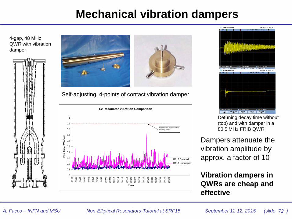
I-2 Resonator Vibration Comparison
0
0.1
0.2
0.3
0.4
0.5
0.6
0.7
0.8
0.9
1
9:4
4
9:4
6
9:4
8
9:5
0
9:5
2
9:5
4
9:5
6
9:5
8
10:0
0
10:0
2
10:1
2
10:1
4
10:1
6
10:1
8
10:2
0
10:2
2
10:2
4
10:2
6
10:2
8
10:3
0
10:3
2
10:3
4
10:3
6
10:3
8
Time
Fast
Tu
ner
Win
do
w
R112 Damped
R113 Undamped
R112 Average Vibration Before
Installing Damper
Mechanical vibration dampers
Dampers attenuate the
vibration amplitude by
approx. a factor of 10
Vibration dampers in
QWRs are cheap and
effective
4-gap, 48 MHz
QWR with vibration
damper
Detuning decay time without
(top) and with damper in a
80.5 MHz FRIB QWR
Self-adjusting, 4-points of contact vibration damper

A. Facco – INFN and MSU Non-Elliptical Resonators-Tutorial at SRF15 September 11-12, 2015 (slide )
Beam Steering in QWRs
• Lack of symmetry in QWRs can produce transverse E
and B fields along the beam axis. This can cause beam
steering and serious problems in beam transport
• Unwanted field components have different shapes and
time dependence compared to accelerating field
• Steering adds to the rf defocusing which given by every
accelerating gaps to beams out of axis
QWR rf gaps: on axis both
Ey and Bx are present
Ideal rf gap: E and B
cylindrically symmetric;
on axis only Ez with no
transverse components
beam
73
A. Facco – INFN and MSU Non-Elliptical Resonators-Tutorial at SRF15 September 11-12, 2015 (slide )
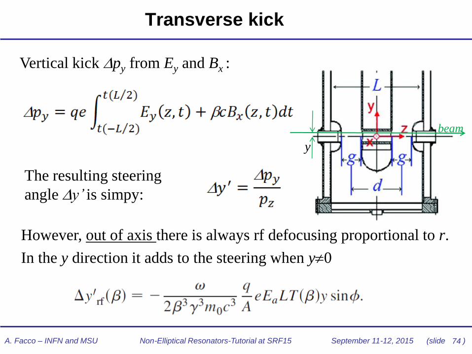
Transverse kick
Vertical kick py from Ey and Bx :
The resulting steering
angle y’ is simpy:
However, out of axis there is always rf defocusing proportional to r.
In the y direction it adds to the steering when y0
y
beam
74

A. Facco – INFN and MSU Non-Elliptical Resonators-Tutorial at SRF15 September 11-12, 2015 (slide )
On axis steering at typical acceleration =-30°
• Electric steering is 0 at 0 and small
above 0
• Magnetic steering is nearly
maximum at 0
• Ey and Bx are comparable and 1%
the accelerating field
0
Steering in a coaxial 0=0.075 QWR
QWR fields
along beam axis
75

A. Facco – INFN and MSU Non-Elliptical Resonators-Tutorial at SRF15 September 11-12, 2015 (slide )
QWR Steering general formula
• Working out the previous formulas we find: (Phys. Rev. ST Accel. Beams 14, 070101 (2011))
All terms :
1. are proportional to acceleration gradient and equally depending on the
beam phase
2. have different transit time factors T() and different optimum 0’s
3. have different geometrical factors G
4. have different dependance on 1/n
5. The rf defocusing term gives a vertical steering proportional to the
vertical distance y of the beam from the geometrical beam tubes axis
• Playing with the cavity geometry and with the beam axis position – all terms
inside brackets - we can perform steering correction
• This correction will work at any gradient Ea and phase !
magnetic electric Rf defocusing
76

A. Facco – INFN and MSU Non-Elliptical Resonators-Tutorial at SRF15 September 11-12, 2015 (slide )
1st Correction Method: beam axis displacement
• B steering and rf defocusing
have a rather similar TTF and
shape.
• By shifting the input beam up
(thus at a positive y) by an
appropriate amount, it is
possible to cancel steering
• This is particularly effective
especially at lower , where
steering it is stronger
77

A. Facco – INFN and MSU Non-Elliptical Resonators-Tutorial at SRF15 September 11-12, 2015 (slide )
2nd Correction Method: Beam Port Tilting
• Beam port tilting creates additional Ey steering terms which can be
properly shaped to cancel steering almost completely near and above 0
1 1
2 2
78
79 A. Facco – INFN and MSU Non-Elliptical Resonators-Tutorial at SRF15 September 11-12, 2015 (slide )
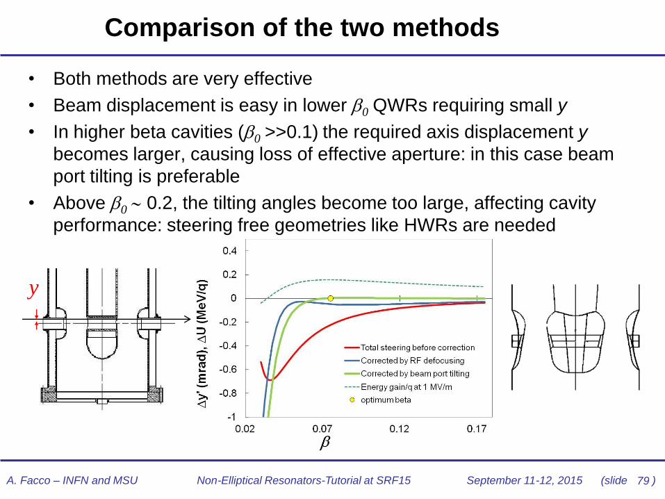
Comparison of the two methods
0
• Both methods are very effective
• Beam displacement is easy in lower 0 QWRs requiring small y
• In higher beta cavities (0 >>0.1) the required axis displacement y
becomes larger, causing loss of effective aperture: in this case beam
port tilting is preferable
• Above 0 0.2, the tilting angles become too large, affecting cavity
performance: steering free geometries like HWRs are needed
y
80 A. Facco – INFN and MSU Non-Elliptical Resonators-Tutorial at SRF15 September 11-12, 2015 (slide )
Non-elliptical cavities integration in
cryomodules
81 A. Facco – INFN and MSU Non-Elliptical Resonators-Tutorial at SRF15 September 11-12, 2015 (slide )
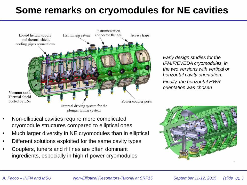
Some remarks on cryomodules for NE cavities
• Non-elliptical cavities require more complicated
cryomodule structures compared to elliptical ones
• Much larger diversity in NE cryomodules than in elliptical
• Different solutions exploited for the same cavity types
• Couplers, tuners and rf lines are often dominant
ingredients, especially in high rf power cryomodules
Early design studies for the
IFMIF/EVEDA cryomodules, in
the two versions with vertical or
horizontal cavity orientation.
Finally, the horizontal HWR
orientation was chosen

82 A. Facco – INFN and MSU Non-Elliptical Resonators-Tutorial at SRF15 September 11-12, 2015 (slide )
Vacuum scheme in low-β cryomodules
Many low-β cryostats working at 4.2K
have only one common vacuum inside
and outside the resonators
• cryostat design and assembly simplified
• possible contamination of rf surfaces from outside the resonator
• In spite of that, very high Q can be maintained for years in on-line resonators
• Q degradation only when the cryostat is vented from outside the resonators
• Provide clean venting, and common vacuum will be (nearly) as reliable as separate one (at least at 4.2K)!
Design objectives in every accelerator cryostat: cryogenic efficiency,
easy installation and maintenance, stable and reliable operation
Common vacuum cryostat (TRIUMF)
83 A. Facco – INFN and MSU Non-Elliptical Resonators-Tutorial at SRF15 September 11-12, 2015 (slide )
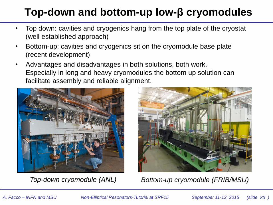
Top-down and bottom-up low-β cryomodules
• Top down: cavities and cryogenics hang from the top plate of the cryostat
(well established approach)
• Bottom-up: cavities and cryogenics sit on the cryomodule base plate
(recent development)
• Advantages and disadvantages in both solutions, both work.
Especially in long and heavy cryomodules the bottom up solution can
facilitate assembly and reliable alignment.
Top-down cryomodule (ANL) Bottom-up cryomodule (FRIB/MSU)
84 A. Facco – INFN and MSU Non-Elliptical Resonators-Tutorial at SRF15 September 11-12, 2015 (slide )
Non-Elliptical Resonators
End of Part I
Thank you
(and see you tomorrow for Part II)

A. Facco
INFN/LNL and FRIB/MSU
SRF2015 – Whistler, BC, Canada
Tutorial n.7
Non-Elliptical Resonators
Part II

86 A. Facco – INFN and MSU Non-Elliptical Resonators-Tutorial at SRF15 September 11-12, 2015 (slide )
SRF Deflecting Cavities
A. Facco – INFN and MSU Non-Elliptical Resonators-Tutorial at SRF15 September 11-12, 2015 (slide )
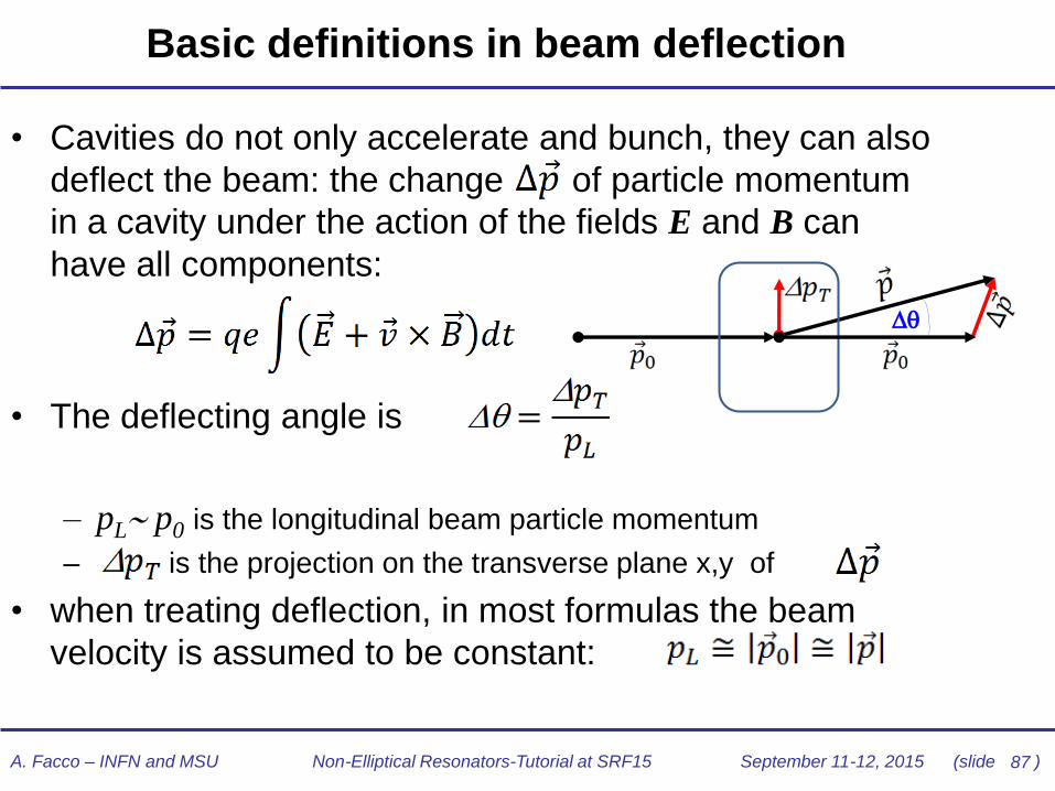
Basic definitions in beam deflection
• Cavities do not only accelerate and bunch, they can also
deflect the beam: the change of particle momentum
in a cavity under the action of the fields E and B can
have all components:
• The deflecting angle is
– pL p0 is the longitudinal beam particle momentum
– is the projection on the transverse plane x,y of
• when treating deflection, in most formulas the beam
velocity is assumed to be constant:
87

88 A. Facco – INFN and MSU Non-Elliptical Resonators-Tutorial at SRF15 September 11-12, 2015 (slide )
Voltage and Gradient in Deflecting Cavities
For deflecting cavities it is useful to define a “deflecting voltage” VT
In typical cavities deflecting the beam in the x-z plane,
Starting from VT , if L is the cavity effective length, a deflecting field (or
gradient) can be defined:
To maximize the time under the deflecting field (1/2 rf cycle),
This way deflection simply becomes
89 A. Facco – INFN and MSU Non-Elliptical Resonators-Tutorial at SRF15 September 11-12, 2015 (slide )
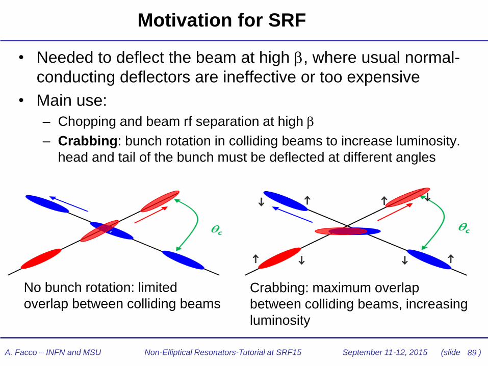
Motivation for SRF
• Needed to deflect the beam at high , where usual normal-
conducting deflectors are ineffective or too expensive
• Main use:
– Chopping and beam rf separation at high
– Crabbing: bunch rotation in colliding beams to increase luminosity.
head and tail of the bunch must be deflected at different angles
No bunch rotation: limited
overlap between colliding beams
Crabbing: maximum overlap
between colliding beams, increasing
luminosity
90 A. Facco – INFN and MSU Non-Elliptical Resonators-Tutorial at SRF15 September 11-12, 2015 (slide )
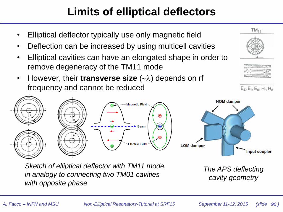
Limits of elliptical deflectors
• Elliptical deflector typically use only magnetic field
• Deflection can be increased by using multicell cavities
• Elliptical cavities can have an elongated shape in order to
remove degeneracy of the TM11 mode
• However, their transverse size () depends on rf
frequency and cannot be reduced
Sketch of elliptical deflector with TM11 mode,
in analogy to connecting two TM01 cavities
with opposite phase
The APS deflecting
cavity geometry

91 A. Facco – INFN and MSU Non-Elliptical Resonators-Tutorial at SRF15 September 11-12, 2015 (slide )
Quest for compact deflecting cavities
• New applications – e.g. crabbing at LHC – require compact resonators
working at low frequency with low transverse dimensions to fit the limited
space between beam lines
• A new generation of TEM (and TE) type deflecting resonators with small
transverse size has been developed
Dimensional
constraints for
deflecting systems
under construction.
400 MHz LHC
crabbing system
499 MHz JLAB Upgrade
deflecting system
92 A. Facco – INFN and MSU Non-Elliptical Resonators-Tutorial at SRF15 September 11-12, 2015 (slide )
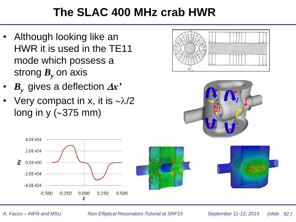
The SLAC 400 MHz crab HWR
• Although looking like an
HWR it is used in the TE11
mode which possess a
strong By on axis
• By gives a deflection x’
• Very compact in x, it is /2
long in y (375 mm)
93 A. Facco – INFN and MSU Non-Elliptical Resonators-Tutorial at SRF15 September 11-12, 2015 (slide )
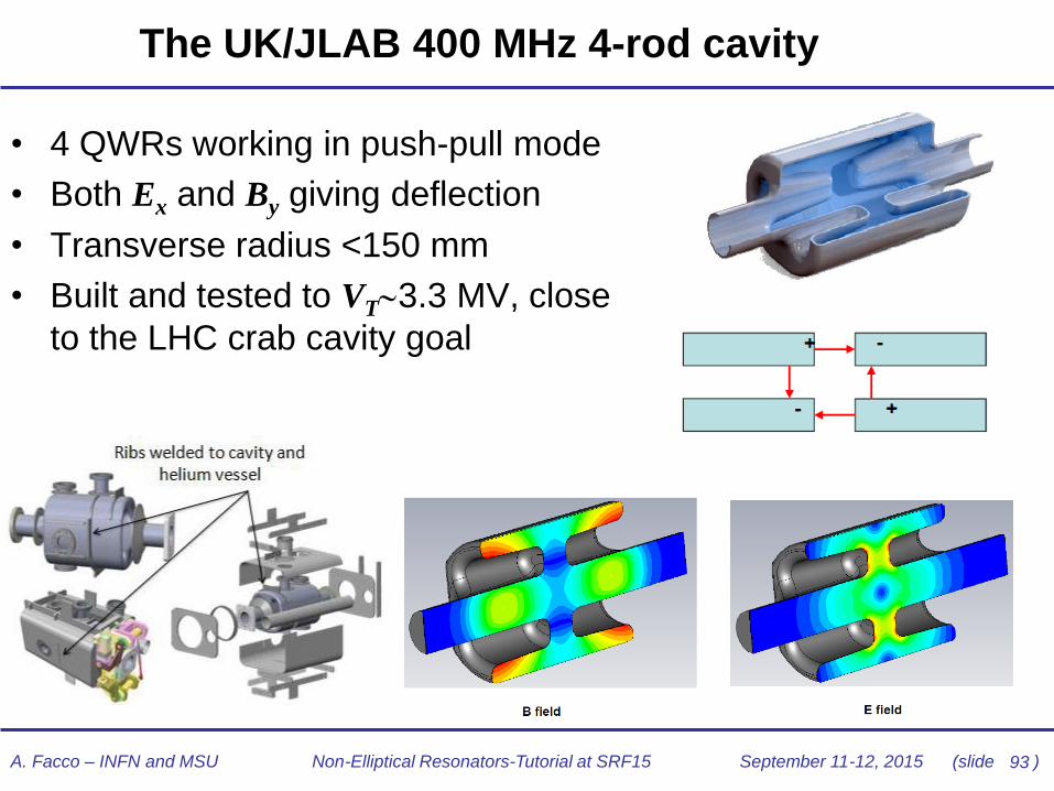
The UK/JLAB 400 MHz 4-rod cavity
• 4 QWRs working in push-pull mode
• Both Ex and By giving deflection
• Transverse radius <150 mm
• Built and tested to VT3.3 MV, close
to the LHC crab cavity goal
94 A. Facco – INFN and MSU Non-Elliptical Resonators-Tutorial at SRF15 September 11-12, 2015 (slide )
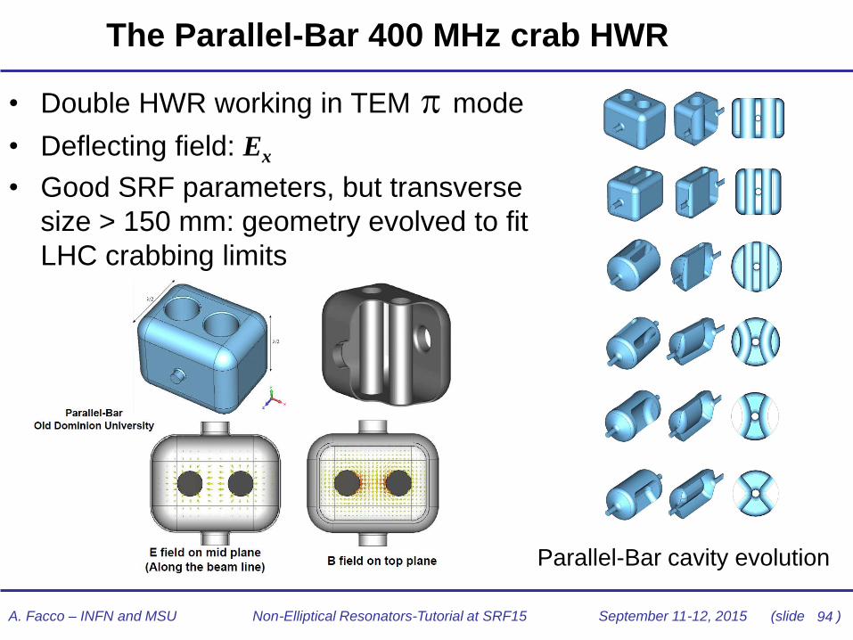
The Parallel-Bar 400 MHz crab HWR
• Double HWR working in TEM mode
• Deflecting field: Ex
• Good SRF parameters, but transverse
size > 150 mm: geometry evolved to fit
LHC crabbing limits
Parallel-Bar cavity evolution

95 A. Facco – INFN and MSU Non-Elliptical Resonators-Tutorial at SRF15 September 11-12, 2015 (slide )
The ODU Rf-Dipole 400 MHz crab cavity
• Ultimate evolution from Parallel-
Bar geometry: TEM mode
became similar to the TE one of
an IH structure, or even to the
TEM of a QWR
• Deflecting field: Ex
• Size fitting LHC crab system
• Prototype built and tested to VT
> 7 MV (LHC goal: > 3.34 MV)
Surface E and B distribution

96 A. Facco – INFN and MSU Non-Elliptical Resonators-Tutorial at SRF15 September 11-12, 2015 (slide )
The BNL 400 MHz double QWR
• Double QWR operated in
push-pull mode
• Deflecting field: Ex
• Transverse size fitting LHC
crab cavity limits
• Proof of principle prototype
built and tested cw to
VT>3MV limited by rf power;
VT>4.5 in pulsed mode (LHC
goal: > 3.34 MV)
• 2° generation prototype under
construction

A. Facco – INFN and MSU Non-Elliptical Resonators-Tutorial at SRF15 September 11-12, 2015 (slide )
State of the art in Non-Elliptical cavities
97
A. Facco – INFN and MSU Non-Elliptical Resonators-Tutorial at SRF15 September 11-12, 2015 (slide )
Design, Construction and Treatments
• Design. Powerful tools – mainly simulation codes - exist for cavity design optimization in all aspects (RF, mechanical, thermal, magnetic,…). These tools are challenged even more in Non-Elliptical cavities than in Elliptical ones, due to their intrinsic complexity and variety
• Construction. Construction and welding technology is steadily improving, thus the quality and reproducibility of the final cavities produced. The quality of commercially available high-RRR Nb is nowadays very high
• Processing. All treatments and techniques developed for elliptical cavities and bringing record performance are now applied also in non elliptical ones
• Large scale production. All state-of-the-art procedures and treatments for Nb cavities once limited to a few research laboratories can now be handled by industry
98

99 A. Facco – INFN and MSU Non-Elliptical Resonators-Tutorial at SRF15 September 11-12, 2015 (slide )
Quarter-wave stuctures: Quarter-Wave resonators
+ Compact
+ Modular
+ High performance
+ Relatively low cost
+ Easy access (in the open ones)
+ Down to very low beta
- Dipole steering for higher β QWRs
- Mechanical stability for lower f QWRs
ANL 4-gap QWR family
48≤f≤162 MHz, 0.001≤β0≤0.2 Superconducting QWR familyLNL 2-gap QWRs family
Very successful
Largest family in operation

100 A. Facco – INFN and MSU Non-Elliptical Resonators-Tutorial at SRF15 September 11-12, 2015 (slide )
Some of the QWRs worldwide…
72 MHz, (FRIB/ MSU)
72 MHz,
=0.077
(ANL)
109 MHz,
=0.15
(ANL)
TRIUMF
INFN LNL&MSU
160 MHz, =0.12
INFN LNL
(sputtered)
New Dehli
INFN LNL
Saclay IPNO
101 MHz, =0.1
HIE/ISOLDE (CERN)
101 A. Facco – INFN and MSU Non-Elliptical Resonators-Tutorial at SRF15 September 11-12, 2015 (slide )
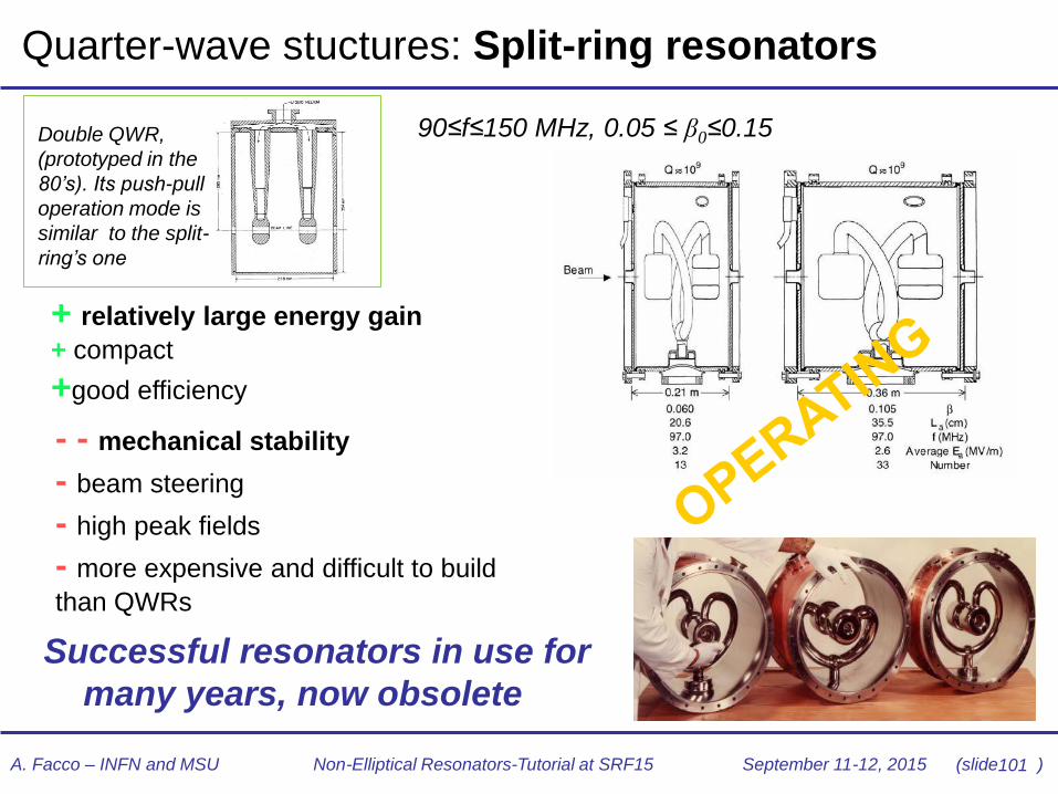
Quarter-wave stuctures: Split-ring resonators
+ relatively large energy gain
+ compact
+good efficiency
- - mechanical stability
- beam steering
- high peak fields
- more expensive and difficult to build
than QWRs
90≤f≤150 MHz, 0.05 ≤ β0≤0.15
Successful resonators in use for
many years, now obsolete
Double QWR,
(prototyped in the
80’s). Its push-pull
operation mode is
similar to the split-
ring’s one

102 A. Facco – INFN and MSU Non-Elliptical Resonators-Tutorial at SRF15 September 11-12, 2015 (slide )
Half-wave structures: Half-Wave resonators (coaxial)
+ Most of the QWRs virtues
+ + No dipole steering
+ Lower Ep than QWRs
- Not easy access
- Difficult to tune (but new techniques coming)
- Less efficient than QWRs
The first 355
MHz SC HWR
ANL - β=0.12
160≤f≤352 MHz, 0.09 ≤ β0≤ 0.53
SARAF/ACCEL
176 MHz, β=0.09
The first SC HWR in
an operating linac
Very successful
Ideal around 150÷300 MHz
competing with single Spoke
FRIB/MSU 322 MHz HWRs

162.5 MHz, =0.1 HWRs (IMP)
103 A. Facco – INFN and MSU Non-Elliptical Resonators-Tutorial at SRF15 September 11-12, 2015 (slide )
Some of the HWRs worldwide…
322 MHz, =0.29 & = 0.53 HWRs
(FRIB/MSU)
352 MHz, =0.17 & = 0.31
HWRs (INFN)
162.5 MHz, =0.11 HWR (ANL)
325 MHz, =0.3 HWR
(ANL)

104 A. Facco – INFN and MSU Non-Elliptical Resonators-Tutorial at SRF15 September 11-12, 2015 (slide )
Half-wave structures: Single-SPOKE resonators
+ All virtues of coaxial HWRs
+ they can work at higher frequency than
coaxial HWRs
+ they can be stacked in multi-gap cavities
- Larger size than HWRs, too large below ~350 MHz
- More expensive than HWRs
LANL β=0.4
SPOKE
345≤f≤805 MHz, 0.15 ≤ β0≤ 0.62
IPNO SPOKE, β=0.35
352 MHz
very successful R&D
the most prototyped around 350 MHz,
will be soon used in accelerators

105 A. Facco – INFN and MSU Non-Elliptical Resonators-Tutorial at SRF15 September 11-12, 2015 (slide )
Some of the Single SPOKE worldwide…
350 MHz, =0.175 (LANL)
352 MHz, =0.12 (IHEP)
325 MHz, =0.22 & =0.51 (FNAL)
352 MHz, =0.15
(IPNO)
106 A. Facco – INFN and MSU Non-Elliptical Resonators-Tutorial at SRF15 September 11-12, 2015 (slide )
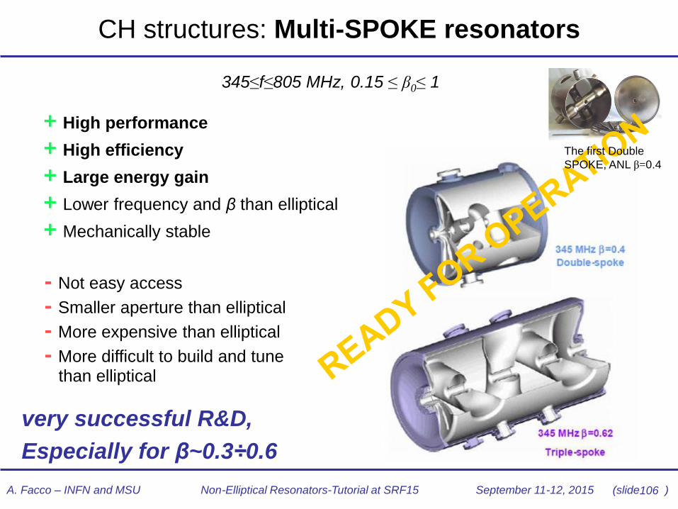
CH structures: Multi-SPOKE resonators
+ High performance
+ High efficiency
+ Large energy gain
+ Lower frequency and β than elliptical
+ Mechanically stable
- Not easy access
- Smaller aperture than elliptical
- More expensive than elliptical
- More difficult to build and tune than elliptical
345≤f≤805 MHz, 0.15 ≤ β0≤ 1
very successful R&D,
Especially for β~0.3÷0.6
The first Double
SPOKE, ANL β=0.4

107 A. Facco – INFN and MSU Non-Elliptical Resonators-Tutorial at SRF15 September 11-12, 2015 (slide )
352 MHz, =0.5
(ESS)
500 MHz, =1
(ODU-JLAB)
345 MHz, =0.5 & =0.63 (ANL)
Some of the Multi-Spoke structures worldwide…

108 A. Facco – INFN and MSU Non-Elliptical Resonators-Tutorial at SRF15 September 11-12, 2015 (slide )
CH structures: Superconducting RFQ
+ Compact
+ CW operation
+ High efficiency
+ Down to very low beta
+ large acceptance
INFN/LNL SRFQ2, A/q=8.5
- Mechanical stability, powerful fast
tuners required
- Not easy to build
- strong MP and FE
- Cost
80 MHz, 0.001≤ β0≤0.035
Efficient but challenging alternative to NC cw RFQs.
Unique development: only 2 units operating in couple
109 A. Facco – INFN and MSU Non-Elliptical Resonators-Tutorial at SRF15 September 11-12, 2015 (slide )
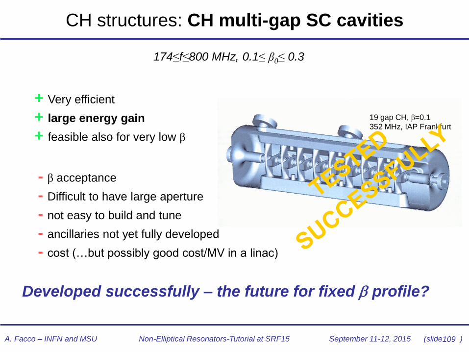
CH structures: CH multi-gap SC cavities
+ Very efficient
+ large energy gain
+ feasible also for very low β
19 gap CH, β=0.1
352 MHz, IAP Frankfurt
- β acceptance
- Difficult to have large aperture
- not easy to build and tune
- ancillaries not yet fully developed
- cost (…but possibly good cost/MV in a linac)
174≤f≤800 MHz, 0.1≤ β0≤ 0.3
Developed successfully – the future for fixed profile?

110 A. Facco – INFN and MSU Non-Elliptical Resonators-Tutorial at SRF15 September 11-12, 2015 (slide )
Some of the CH structures worldwide…
217 MHz ,15 gap CH, β=0.059 (IAP)
A. Facco – INFN and MSU Non-Elliptical Resonators-Tutorial at SRF15 September 11-12, 2015 (slide )
Open issues
• Many old problems solved. Still open issues: – Q-slope problems, especially at 4.2K, but also at 2K at
high field (HFQS). TM cavities results not yet achieved
– Mechanical stability: in some cavities still large LFD and df/dP, and mechanical modes requiring large bandwidths
– Performance reproducibility: still below elliptical cavities.
This imposes by design a large safety margin between operational specifications and prototypes performance
• Non-Elliptical geometries are more complicated than elliptical ones and produce more complex behavior. It is more difficult to obtain perfect cavities, but results are getting closer and closer
111
A. Facco – INFN and MSU Non-Elliptical Resonators-Tutorial at SRF15 September 11-12, 2015 (slide )
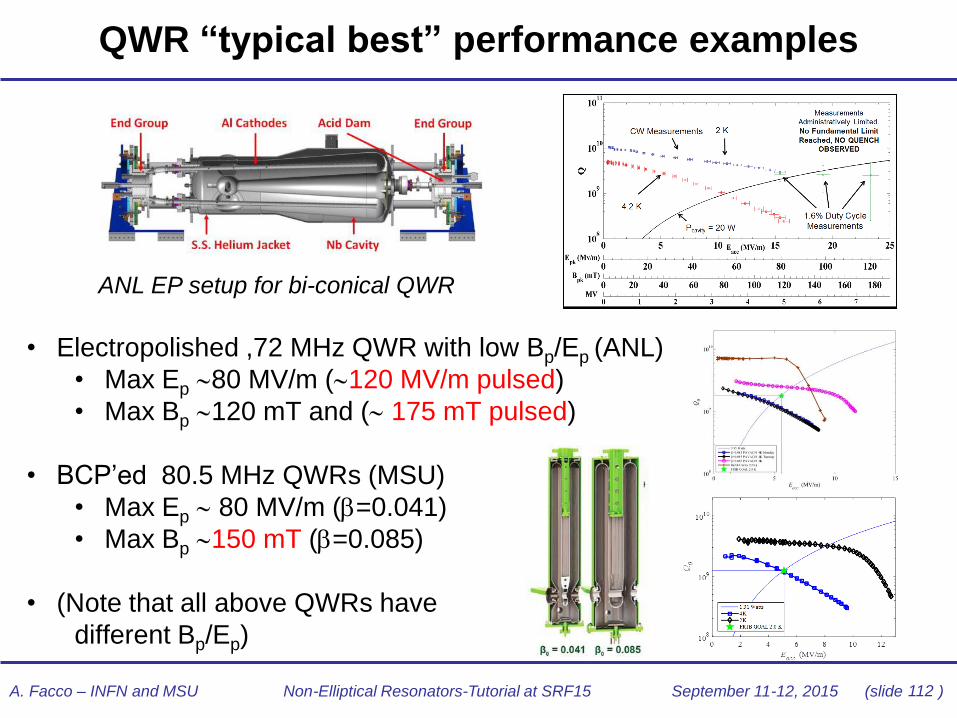
• Electropolished ,72 MHz QWR with low Bp/Ep (ANL)
• Max Ep 80 MV/m (120 MV/m pulsed)
• Max Bp 120 mT and ( 175 mT pulsed)
• BCP’ed 80.5 MHz QWRs (MSU)
• Max Ep 80 MV/m (=0.041)
• Max Bp 150 mT (=0.085)
• (Note that all above QWRs have
different Bp/Ep)
QWR “typical best” performance examples
ANL EP setup for bi-conical QWR
112

113 A. Facco – INFN and MSU Non-Elliptical Resonators-Tutorial at SRF15 September 11-12, 2015 (slide )
• Electropolished ,162.5 MHz HWR with low Bp/Ep (ANL)
• Max Ep 90 MV/m
• Max Bp 100 mT
• BCP’ed 322 MHz HWR (MSU)
• Max Ep 73 MV/m
• Max Bp 130 mT
HWR “typical best” performance examples
ANL for bi-conical HWR under EP
MSU 322 MHz HWR

114 A. Facco – INFN and MSU Non-Elliptical Resonators-Tutorial at SRF15 September 11-12, 2015 (slide )
• BCP’ed, 325 MHz Single Spoke (FNAL)
• Max Ep 85 MV/m
• Max Bp 125 mT
• Electropolished, 345 MHz
Triple-Spoke (ANL)
• Max Bp 117 mT
SPOKE “typical best” performance examples
FNAL 325 MHz Single Spoke cavity
115 A. Facco – INFN and MSU Non-Elliptical Resonators-Tutorial at SRF15 September 11-12, 2015 (slide )
Non-Elliptical cavities: final remarks
• Non elliptical cavities are becoming as widespread as elliptical ones, built
and treated with similar techniques and in a large scale.
• Several ambitious projects of high intensity p, d and heavy ion CW linacs
prompted low- SRF technology to step from “artists’ creations” to
industrial hi-tech production aiming at performance and reliability
• Recent developments: high current, crabbing, and =1 spoke cavities
• Some new large projects chose 2K to increase operation Q and Ea
• Best performance are approaching elliptical TM ones; the required SRF
technology is now industrially available
• Still open issues: Q-slope and best performance reproducibility
• Recent great achievements of “Nitrogen doping” technique might further
raise the bar in high Q and Ea also for non-elliptical cavities
This is a growing technology: there is still a lot to do
New good ideas will be welcome!

116 A. Facco – INFN and MSU Non-Elliptical Resonators-Tutorial at SRF15 September 11-12, 2015 (slide )
Thanks also to all people who have contributed in the field and have provided
precious material for this tutorial
Thank you