(non-nav models only) 99-8222 99-8222br · kit assembly 99-8222 8 double din or stacked iso mount...
TRANSCRIPT
METRA. THE WORLD’S BEST KITS.™
© COPYRIGHT 2004-2011 METRA ELECTRONICS CORPORATION
APPLICATIONS
1-800-221-0932 metraonline.com
INSTALLATION INSTRUCTIONS FOR PART 99-8222
WIRING & ANTENNA CONNECTIONS (Sold Separately) Wiring Harness: • 70-1761 Toyota harness 1987-up • TYTO-01 Toyota amp interface harness 2003-upAntenna Adapter: • Not Required
Panel Removal Tool • Phillips Screwdriver • Small Flat Blade Screwdriver • Socket Wrench
TOOLS REQUIRED
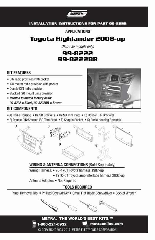
Toyota Highlander 2008-up(Non-nav models only)
99-822299-8222BR
• DIN radio provision with pocket• ISO mount radio provision with pocket• Double DIN radio provision• Stacked ISO mount units provision• Painted to match factory dash: 99-8222 = Black, 99-8222BR = Brown
B D
F
C E
G
A
• A) Radio Housing • B) ISO Brackets • C) ISO Trim Plate • D) Double DIN Brackets • E) Double DIN/Stacked ISO Trim Plate • F) Snap in Pocket • G) Radio Housing Brackets
KIT FEATURES
KIT COMPONENTS
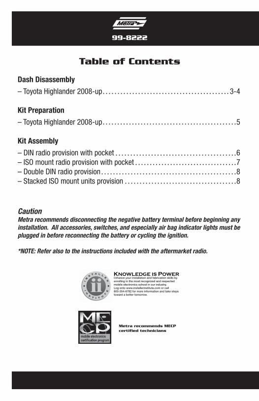
Table of Contents
Dash Disassembly
– Toyota Highlander 2008-up 3-4
Kit Preparation
– Toyota Highlander 2008-up 5
Kit Assembly
– DIN radio provision with pocket 6– ISO mount radio provision with pocket 7– Double DIN radio provision 8– Stacked ISO mount units provision 8
KNOWLEDGE IS POWEREnhance your installation and fabrication skills by enrolling in the most recognized and respected mobile electronics school in our industry.Log onto www.installerinstitute.com or call 800-354-6782 for more information and take steps toward a better tomorrow.
Metra recommends MECP certified technicians
99-8222
CautionMetra recommends disconnecting the negative battery terminal before beginning any installation. All accessories, switches, and especially air bag indicator lights must be plugged in before reconnecting the battery or cycling the ignition.
*NOTE: Refer also to the instructions included with the aftermarket radio.
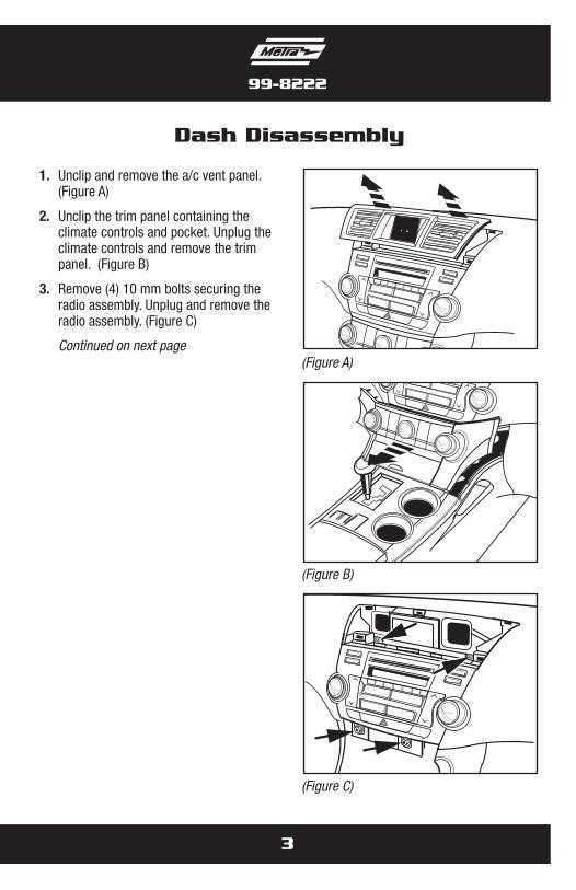
1. Unclip and remove the a/c vent panel. (Figure A)
2. Unclip the trim panel containing the climate controls and pocket. Unplug the climate controls and remove the trim panel. (Figure B)
3. Remove (4) 10 mm bolts securing the radio assembly. Unplug and remove the radio assembly. (Figure C)
Continued on next page
3
Dash Disassembly
99-8222
(Figure A)
(Figure B)
(Figure C)
4
99-8222
Dash Disassembly
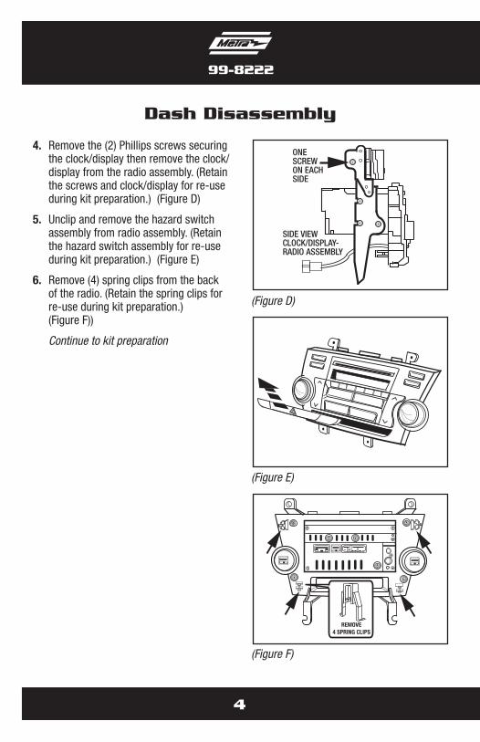
4. Remove the (2) Phillips screws securing the clock/display then remove the clock/display from the radio assembly. (Retain the screws and clock/display for re-use during kit preparation.) (Figure D)
5. Unclip and remove the hazard switch assembly from radio assembly. (Retain the hazard switch assembly for re-use during kit preparation.) (Figure E)
6. Remove (4) spring clips from the back of the radio. (Retain the spring clips for re-use during kit preparation.) (Figure F))
Continue to kit preparation
ONESCREWON EACHSIDE
SIDE VIEWCLOCK/DISPLAY-RADIO ASSEMBLY
REMOVE4 SPRING CLIPS
(Figure D)
(Figure E)
(Figure F)
5
99-8222
Kit Preparation
PASSENGER
(Figure B)
(Figure A)
(Figure C)
ATTACH4 SPRING CLIPS
(Figure D)
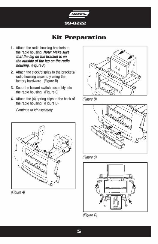
1. Attach the radio housing brackets to the radio housing. Note: Make sure that the leg on the bracket is on the outside of the leg on the radio housing. (Figure A)
2. Attach the clock/display to the brackets/radio housing assembly using the factory hardware. (Figure B)
3. Snap the hazard switch assembly into the radio housing. (Figure C)
4. Attach the (4) spring clips to the back of the radio housing. (Figure D)
Continue to kit assembly
Kit Assembly 99-8222
6
DIN radio provision with pocket
(Figure A)
(Figure B)
(Figure C)
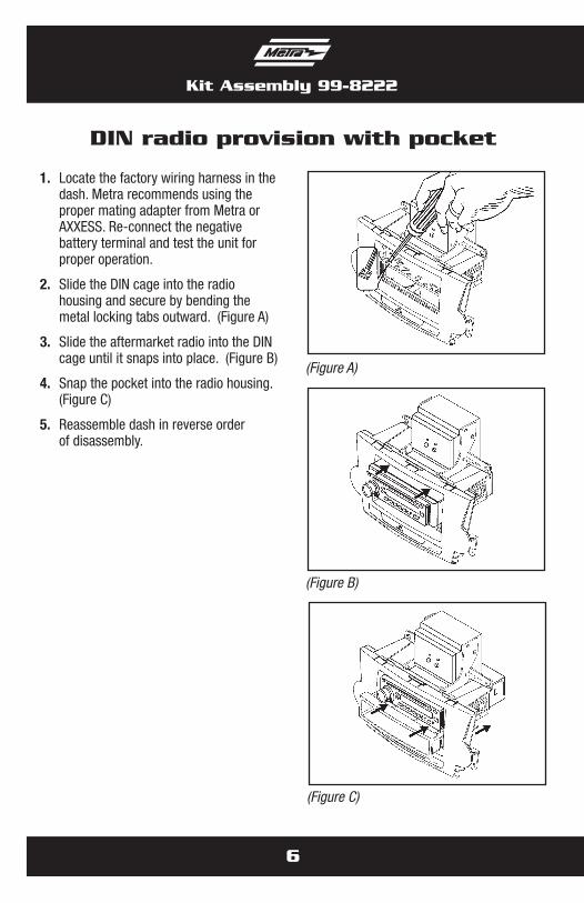
1. Locate the factory wiring harness in the dash. Metra recommends using the proper mating adapter from Metra or AXXESS. Re-connect the negative battery terminal and test the unit for proper operation.
2. Slide the DIN cage into the radio housing and secure by bending the metal locking tabs outward. (Figure A)
3. Slide the aftermarket radio into the DIN cage until it snaps into place. (Figure B)
4. Snap the pocket into the radio housing. (Figure C)
5. Reassemble dash in reverse order of disassembly.
Kit Assembly 99-8222
7
ISO mount radio provision with pocket
(Figure A)
(Figure B)
(Figure C)
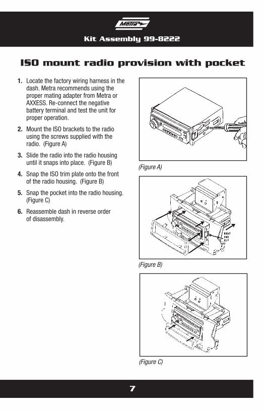
1. Locate the factory wiring harness in the dash. Metra recommends using the proper mating adapter from Metra or AXXESS. Re-connect the negative battery terminal and test the unit for proper operation.
2. Mount the ISO brackets to the radio using the screws supplied with the radio. (Figure A)
3. Slide the radio into the radio housing until it snaps into place. (Figure B)
4. Snap the ISO trim plate onto the front of the radio housing. (Figure B)
5. Snap the pocket into the radio housing. (Figure C)
6. Reassemble dash in reverse order of disassembly.
Kit Assembly 99-8222
8
Double DIN or stacked ISO mount units provision
(Figure A)
(Figure B)
(Figure C)
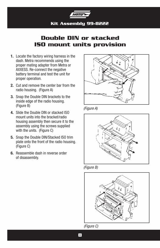
1. Locate the factory wiring harness in the dash. Metra recommends using the proper mating adapter from Metra or AXXESS. Re-connect the negative battery terminal and test the unit for proper operation.
2. Cut and remove the center bar from the radio housing. (Figure A)
3. Snap the Double DIN brackets to the inside edge of the radio housing. (Figure B)
4. Slide the Double DIN or stacked ISO mount units into the bracket/radio housing assembly then secure it to the assembly using the screws supplied with the units. (Figure C)
5. Snap the Double DIN/Stacked ISO trim plate onto the front of the radio housing. (Figure C)
6. Reassemble dash in reverse order of disassembly.

Notes

Notes
Notes

METRA. THE WORLD’S BEST KITS.™
© COPYRIGHT 2004-2011 METRA ELECTRONICS CORPORATION 1-800-221-0932 metraonline.com
INSTALLATION INSTRUCTIONS FOR PART 99-8222
REV.
5/2
3/11