non-potable water - camrosa water district...non-potable water notes, and exeptions 1.1 introduction...
TRANSCRIPT
NON-POTABLE WATER
DESIGN, CONSTRUCTION, and USE
STANDARDS
CAMROSA WATER DISTRICT ENGINEERING DEPARTMENT 7385 SANTA ROSA ROAD
CAMARILLO, CA 93012

NON-POTABLE WATER SPECIFICATIONS
TABLE OF CONTENTS
Section 1- Introduction, General Policies, Non-potable Water Notes, and Exceptions
1.1 Introduction
A. Groundwater B. Surface Water C. Treated Wastewater D. Non-portable Water System
1.2 Design and Construction 1.3 District Authority 1.4 Interpretation 1.5 Applicable Codes and Policies 1.6 Responsibility of Developers 1.7 Non-potable General Notes 1.8 Abbreviations and Definitions 1.9 Exceptions to the requirement for the Installation of Non-potable System Section 2- Design Criteria 2.1 Camrosa Non-potable System
A. General B. Interconnection C. Storage
2.2 Water Main Pressures, capacity, and Sizes
D. Pressure E. Velocity F. Sizing of Mains
2.3 Selection and Types of Pipe
A. General B. Main Pipelines C. Service Lines
2.4 Location of Lines in Streets
A. Water Mains
Non-Potable Water Standards, Table of Contents Page 1 of 12

B. Criteria for the Separation of Potable and Non-potable Water Mains 1. General 2. Basic Separation Standards 3. Exception to Basic Separation Standard 4. Special Provisions
2.5 Location of Lines (Easements)
A. Width B. Pipeline Location C. Easement Location D. Deeds E. Easement Provision
1. For Subdivisions 2. For Other than Subdivisions
2.6 Depth of Non-potable Water Mains 2.7 Location and Size of Valves 2.8 Air and Vacuum Assemblies
A. Types of Valves B. Location C. Sizing
2.9 Blow-off Assemblies
A. General B. Sizing
2.10 Design for Proper Flushing 2.11 Horizontal and Vertical Curves
A. General B. PVC (AWWA C900) C. Steel Pipe D. Ductile Iron pipe
2.12 Sizing of Water Meters and Service Lines
A. General B. Meter Types C. Meter Sizing D. Service Line Sizing
Non-Potable Water Standards, Table of Contents Page 2 of 12
2.13 Locations for Meter Boxes and Air Releases A. Meter Boxes B. Combination Air Release Assemblies C. Policy on Irrigation Meters.
2.14 Structural requirements
A. Under a Road B. Under Other Pipes and Structures C. Flexible Joints D. Thrust Blocks E. Steep Grades F. Design for Earth Loads
2.15 Special Considerations for Welded Steel Pipe Section 3- Materials 3.1 General Requirements 3.2 Testing and Acceptability of Materials 3.3 Mainline Pipe Materials
A. General B. PVC Pipe
1. Pipe 2. Joint Mechanisms 3. Couplings and Fittings 4. Physical Test Requirements 5. Detectable Ribbon or Tape
C. Steel pipe
1. Pipe 2. Pipe Ends 3. Hydrostatic Tests 4. Mortar Lining and Coating 5. Mortar Lining 6. Field Joints 7. Electrically Bonded Connections 8. Welded Joints 9. Butt Strap Closures
Non-Potable Water Standards, Table of Contents Page 3 of 12

D. Ductile Iron Pipe 1. Pipe 2. Joints 3. Fittings 4. Lining and Coating 5. Encasement
3.4 Mainline Fittings
A. Ductile Iron Fittings B. Flanges, Bolts, and Gaskets C. Mechanical Joint Fittings D. Flexible Couplings E. Transition Couplings F. Flanged Coupling Adaptors G. Insulating Couplings H. Special Steel Pipe Fittings
3.5 Service Line Materials and Fittings
A. Copper Pipe B. Service Saddles C. Corporation (Corp) Stop D. Angle Meter Stop E. Customer Hand Valve F. Polyethylene Sleeve
3.6 Meter Boxes 3.7 Water Meters 3.8 Mainline Valves
A. Butterfly Valves 1. General 2. Valve Body 3. Valve Operators 4. Painting 5. Marking 6. Approved Valves 7. Available end Types
B. Resilient Seated Gate Valves
Non-Potable Water Standards, Table of Contents Page 4 of 12

C. Tapping Sleeves and Valves 1. Tapping Sleeves 2. Tapping Valves 3. Painting and Coating
D. Valve Stacks and Covers 3.9 Combination Air Release Assemblies
A. Mechanical Assembly B. Air/Vac Can C. Service line D. Ball Valves E. Guard Posts
3.10 Blow-off Assemblies
A. 2” Blow-off 1. Service line 2. 2” Ball Valve 3. Vault 4. Plastic Plug
B. 4” Blow-off
1. Service line 2. 4” Valve 3. Flanged Spool 4. 4” Brass Nipple 5. 4” Angle Meter Valve 6. Vault 7. Guard Posts
3.11 Pipe Trench Materials
A. Within Pipe Zone B. Above Pipe Zone C. Special Slurry Backfill
3.12 Roadway Materials 3.13 Concrete Materials 3.14 Reinforcing Steel
A. Rebar B. Mesh
Non-Potable Water Standards, Table of Contents Page 5 of 12

3.15 Painting 3.16 Plastic Film Wrap 3.17 Marker Posts Section 4- Plan Preparation 4.1 General 4.2 Sheet Size and Margins 4.3 Signature Block 4.4 Cover Sheet
A. Index Map B. Vicinity Map C. Benchmark D. General Notes E. Water Service Certification F. As-Built Information
4.5 Plan of Water System 4.6 Profile of Non-Potable System 4.7 Graphic Scales and North Arrow 4.8 Procedure for Approval
A. Requirements for Approval of Construction B. Requirements for Final Acceptance
4.9 Plan Check List
A. Cover Sheet B. General Design C. Plan and Profile Sheets D. Administrative Issues Prior to Beginning Construction
4.10 Language for Dedication of Facilities to the District
A. Grant Deed, Quitclaim Deed, Bill of Sale, or Other B. Easement Deed C. Non-Potable Water Construction Notes
Non-Potable Water Standards, Table of Contents Page 6 of 12

Section 5- Fees, Charges, and Requirements for Authorization of Construction 5.1 General 5.2 Plan Check Fee 5.3 Submittal of Blueline Prints 5.4 Special Provisions 5.5 Inspection Fees
A. Minimum Inspection Fees B. Special Situation Inspection fees
5.6 Easements 5.7 Agreements, Bonds, and Insurance Certification
A. Agreement B. Insurance C. Faithful Performance Bond D. Labor and Materials Bond E. Calleguas Receipt and Release
5.8 Will-Serve Letter 5.9 Approval for Construction 5.10 Special Facilities Surcharge; Fire Flow Surcharge 5.11 Service Line or Meter Installation 5.12 Special Charges 5.13 Mainline Extension and Oversizing Agreements Section 6- Construction Staking 6.1 General Requirements 6.2 Preservation of Stakes 6.3 Service lines 6.4 As-Built
Non-Potable Water Standards, Table of Contents Page 7 of 12
Section 7- Construction 7.1 General Requirements
A. Use of this Section B. Protection/Operation of Existing Potable Water System C. Quality of Materials D. Substitution E. Quality of Workmanship F. Defective Work G. District inspection, Field Acceptance, and Guarantee Period H. Public Relations
7.2 Permits
A. Encroachment B. Explosives
7.3 Shipment and Delivery 7.4 Clearing and Grubbing
A. Grubbing B. Removal and Disposal of Materials
7.5 Utilities, Existing Facilities, and Concrete Removal
A. Abandonment B. Utilities and Existing Facilities C. Concrete or Masonry Construction Removal
7.6 Excavation and Trenching
A. General B. Excavation C. Shoring D. Trench Width and Grade E. Pipe Sub-Grade
7.7 Pipe Bedding and Laying
A. General B. Pipe Laying on Bedding versus Earth Mounds C. Pipe Laying for PVC Pipe D. Pipe Laying for Ductile Iron Pipe
Non-Potable Water Standards, Table of Contents Page 8 of 12
7.8 Thrust Blocks, Support of Valves, etc
A. Supporting of Valves B. Thrust Blocks
7.9 Hot Tapping 7.10 Service Connections and Service Lines 7.11 Installation of Valves and Fittings 7.12 Installation of Air release and Blow-Off Asemblies 7.13 Installation of Meter Boxes and Pressure Regulators 7.14 General
A. Meter Boxes B. Jurisdiction C. Pressure Regulators
7.15 Backfill and Compaction
A. General B. Backfilling the Pipe Zone C. Backfilling Above the Pipe Zone D. Backfill by Tamping Method E. Backfilling by Flooding or Jetting F. Compaction Tests
7.16 Resurfacing and Restoration 7.17 Boring and Jacking Operations
A. General B. Bores C. Jacked Steel Casing
7.18 Concrete Mortar Work 7.19 Painting 7.20 Safety 7.21 Signage
Non-Potable Water Standards, Table of Contents Page 9 of 12
Section 8- Abandonment 8.1 General 8.2 Non-Potable Waterlines 8.3 Structures Section 9- Testing Non-Potable Waterlines 9.1 General 9.2 Hydrostatic Testing
A. General Requirements B. Preparation C. Procedure D. Leakage E. Steel Pipe F. PVC Pipe Differences G. Ductile Pipe Differences H. Possible Causes for Test Failures
9.3 Role of Flushing Section 10- Non-Potable Water System and Work Area Cleanup 10.1 Final Project Cleanup Section 11- Requirements for Final Acceptance 11.1 General
A. Field Acceptance B. Final Acceptance
11.2 Field Acceptance 11.3 “As-Built” Originals 11.4 Notice of Completion 11.5 Grant Deed 11.6 Itemized Cost or Additional Fees
Non-Potable Water Standards, Table of Contents Page 10 of 12
11.7 Other Administrative Items Including Easements 11.8 Fifty Percent Occupancy 11.9 Approval for Acceptance 11.10 Status During Maintenance and Guarantee Period 11.11 Exoneration of Surety
Standard Plate Drawings Not all of the Typical Water Plate Drawings are included here because several do not apply to the construction of non-potable mains and services. Only applicable drawings have been included as listed here and on the Camrosa web page for non-potable specifications. W-1 Thrust Block Layouts for Typical Ductile Fittings W-2 Thrust Block Sizing for Horizontal Pressures W-3 Thrust Block Sizing for Reducers and Tees W-4 Thrust Blocks for Dead-end Ring-tite Pipe W-5 Thrust Blocks for Vertical Bends W-6 Thrust Block Sizing for Vertical Bends W-7 Concrete Protector Wall W-8 Anchor Wall Detail W-9 Slope Protection Detail W-10 Trench Sections for Pipe and Guard Post Detail W-11 Trench Section and Concrete Encasement Detail W-15 Welded Steel and Steel Cylinder Pipe Connection Details W-17 Welded Steel Pipe, Connections to PVC and DIP Details W-18 Mechanical Tapping Sleeve and Tapping Valve for A.C., DIP, and PVC Pipe W-20 Tapping Valve on PVC (Tentative) W-22 Tee in PVC, Transite, or Ductile Main with One Leg Dead-ended W-23 Cast Iron Cross and Valving Details W-24 Cast Iron Cross, Flanged and/or Ring-Tite Valves W-25 Valve Details for Inline or Lateral Pipes W-26 Valve Box Details W-27 Typical Valve Box Installation W-30 Typical End Drain and Blow-off with Copper Tubing W-31 Main Ending in Cul-de-Sac with Service Connections and End Drain (Blow-off) W-32 Large Blow-offs, 4” to 6” W-33 Air and Vacuum Release (Air/Vac) 1” W-34 Air and Vacuum Release 2” W-35 Air and Vacuum Release 4” and Larger W-35-1 Cabinet for Large Air/Vacs.
Non-Potable Water Standards, Table of Contents Page 11 of 12
W-37 Connections to PVC or AC Pipes, 2” and Smaller W-39 Typical Service Installations, Without Meters, 1”, 1 ½”, and 2” W-40 Typical Service Installations W-41 Typical Service Installations with Meters W-42 Meter Box Locations Relative to Sidewalks W-47 Two ¾” or 1” Meters from a Single Service Line, New Construction W-50 Typical Structure Installation, (Meter Box, Air/Vac, Fire Hydrant) in a Slope W-51 Allowable Leakage Chart W-55 Sanitary Protection for Water Mains Crossing Sewers W-56 Trench Section, for Separation of Water Mains and Sewers W-57 (Future) W-58 (Future) W-59 (Future) W-60 (Future)
Non-Potable Water Standards, Table of Contents Page 12 of 12

SECTION I
INTRODUCTION, GENERAL POLICIES, NON-POTABLE WATER NOTES, AND EXEPTIONS
1.1 INTRODUCTION
There are many types and sources of water, drinking water, reclaimed water, recycled water, and non-potable water that can be obtained from lakes, rivers or other surface supply, underground aquifers, and properly treated water reused from a wastewater treatment facility. Non-potable water is water that may contain objectionable pollution, contamination, minerals, or bacterial agents and is considered unsafe and/or unpalatable for drinking. While the various types and sources produce water that is not safe for consumption by humans, it is not hazardous in any way and is considered safe for all other uses, such as the irrigation of food and non-food crops, for residential landscaping, fire fighting, decorative fountains, golf courses, parks and playgrounds, schoolyards, and many other uses that would otherwise require drinking water. The non-potable water is safe for use in nearly every circumstance that drinking water was formerly used with the exception of actually consuming it. For the safest use of the non-potable water, spray, mist, or runoff should not enter dwellings, designated outdoor eating areas, or food handling facilities and drinking water fountains should be protected against contact with non-potable water spray, mist, or runoff. Camrosa utilizes three sources for non-potable water. The sources are: wells that tap underground aquifers; a surface diversion; and water recycled from the Camrosa Water Reclamation Facility. a. Camrosa Water District uses water from wells that produce water appropriate for irrigation purposes but that does not meet the standards for drinking water primarily due to excessive levels of Nitrate. b. The District diverts water from Conejo Creek, just south of the 101 Freeway, where it is raised to a level where it can flow by gravity to holding ponds near Lewis Road where it settles and is pumped back into the non-potable water system. This water is suitable for all irrigation uses and is not hazardous in any way if body contact occurs. c. The last source is the treated water recycled from the Camrosa Water Reclamation Facility. The water is treated to tertiary standards, properly disinfected, and has no restrictions on its use other than consuming it. It is safe for the irrigation of all food crops, body contact, and for use in firefighting.
Non-Potable Water Standards- Section 1, Introduction Page 1 of 11

A. GROUNDWATER As might be expected, groundwater is water confined below the surface of the ground in permeable layers called aquifers. The District utilizes several wells around and within the Santa Rosa Valley. Some have water quality appropriate for drinking water and some do not. The wells that do not meet drinking water standards are pumped into the non-potable water system.
B. SURFACE WATER Surface water is water that accumulates mainly as a result of direct runoff from precipitation that does not enter the ground through infiltration or is not returned to atmosphere by evaporation. It flows over the ground surface and is classified as direct runoff. Direct runoff is water that flows over the ground surface directly into streams, rivers, lakes and oceans. When collected and reused, this water is generally referred to as Reclaimed Water.
In general, surface water is characterized by turbidity, some suspended solids, some color, and microbiological contamination. When destined for use as drinking water, many treatment processes are required. It must be filtered so that the suspended materials are removed, and disinfected to ensure that it is safe for human consumption.
For non-potable uses it is merely collected and pressurized for the intended purposes. It receives some settlement in our ponds and may at times receive some chlorination as a preventative measure to inhibit the growth of slime within the pipelines.
C. TREATED WASTEWATER As part of a completely separate non-potable water system, Camrosa distributes properly treated, filtered, and disinfected effluent from its Water Reclamation Facility. This water is treated to tertiary standards and has no restrictions for its use other than consuming it. It is currently used on food crops in the vicinity of the treatment facility and as a source for irrigation of turf, flowers, and shrubs on the campus of California State University, Channel Islands. This water is generally referred to as Recycled Water. It is not in use within the Santa Rosa Valley non-potable system.
D. CAMROSA WATER DISTRICTS’ NON-POTABLE WATER SYSTEM The primary source of the non-potable system is surface water from the direct runoff into Conejo Creek where it is diverted to our holding ponds, pumped into our Reservoir 1A at hydraulic elevation 425 feet, and delivered to the customers at pressures between 75 and 130psi. This reclaimed water is supplied to customers from the southwest corner of our District to well past the center of the District in the vicinity of Camelot Estates. Many homes in the District have dual services, one for inside use and one for outside irrigation. See Map, Appendix X.
Non-Potable Water Standards- Section 1, Introduction Page 2 of 11
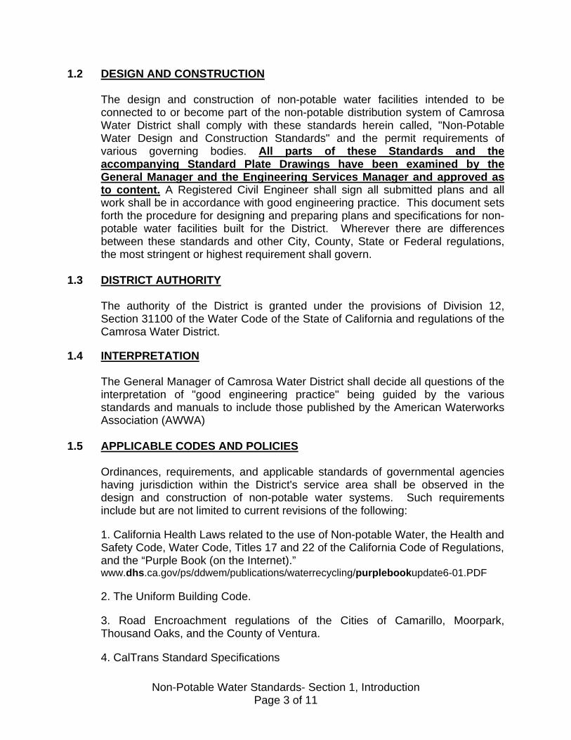
1.2 DESIGN AND CONSTRUCTION The design and construction of non-potable water facilities intended to be connected to or become part of the non-potable distribution system of Camrosa Water District shall comply with these standards herein called, "Non-Potable Water Design and Construction Standards" and the permit requirements of various governing bodies. All parts of these Standards and the accompanying Standard Plate Drawings have been examined by the General Manager and the Engineering Services Manager and approved as to content. A Registered Civil Engineer shall sign all submitted plans and all work shall be in accordance with good engineering practice. This document sets forth the procedure for designing and preparing plans and specifications for non-potable water facilities built for the District. Wherever there are differences between these standards and other City, County, State or Federal regulations, the most stringent or highest requirement shall govern.
1.3 DISTRICT AUTHORITY
The authority of the District is granted under the provisions of Division 12, Section 31100 of the Water Code of the State of California and regulations of the Camrosa Water District.
1.4 INTERPRETATION
The General Manager of Camrosa Water District shall decide all questions of the interpretation of "good engineering practice" being guided by the various standards and manuals to include those published by the American Waterworks Association (AWWA)
1.5 APPLICABLE CODES AND POLICIES
Ordinances, requirements, and applicable standards of governmental agencies having jurisdiction within the District's service area shall be observed in the design and construction of non-potable water systems. Such requirements include but are not limited to current revisions of the following:
1. California Health Laws related to the use of Non-potable Water, the Health and Safety Code, Water Code, Titles 17 and 22 of the California Code of Regulations, and the “Purple Book (on the Internet).” www.dhs.ca.gov/ps/ddwem/publications/waterrecycling/purplebookupdate6-01.PDF 2. The Uniform Building Code. 3. Road Encroachment regulations of the Cities of Camarillo, Moorpark, Thousand Oaks, and the County of Ventura. 4. CalTrans Standard Specifications
Non-Potable Water Standards- Section 1, Introduction Page 3 of 11
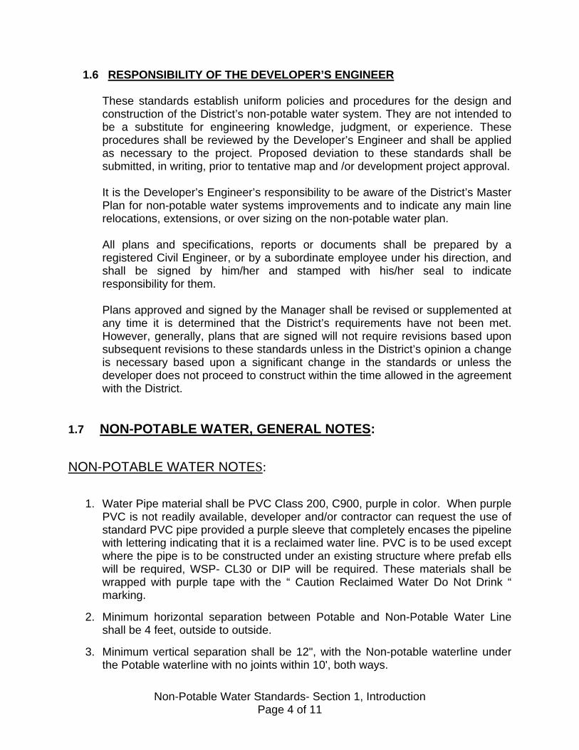
1.6 RESPONSIBILITY OF THE DEVELOPER’S ENGINEER
These standards establish uniform policies and procedures for the design and construction of the District’s non-potable water system. They are not intended to be a substitute for engineering knowledge, judgment, or experience. These procedures shall be reviewed by the Developer’s Engineer and shall be applied as necessary to the project. Proposed deviation to these standards shall be submitted, in writing, prior to tentative map and /or development project approval.
It is the Developer’s Engineer’s responsibility to be aware of the District’s Master Plan for non-potable water systems improvements and to indicate any main line relocations, extensions, or over sizing on the non-potable water plan.
All plans and specifications, reports or documents shall be prepared by a registered Civil Engineer, or by a subordinate employee under his direction, and shall be signed by him/her and stamped with his/her seal to indicate responsibility for them.
Plans approved and signed by the Manager shall be revised or supplemented at any time it is determined that the District’s requirements have not been met. However, generally, plans that are signed will not require revisions based upon subsequent revisions to these standards unless in the District’s opinion a change is necessary based upon a significant change in the standards or unless the developer does not proceed to construct within the time allowed in the agreement with the District.
1.7 NON-POTABLE WATER, GENERAL NOTES:
NON-POTABLE WATER NOTES:
1. Water Pipe material shall be PVC Class 200, C900, purple in color. When purple
PVC is not readily available, developer and/or contractor can request the use of standard PVC pipe provided a purple sleeve that completely encases the pipeline with lettering indicating that it is a reclaimed water line. PVC is to be used except where the pipe is to be constructed under an existing structure where prefab ells will be required, WSP- CL30 or DIP will be required. These materials shall be wrapped with purple tape with the “ Caution Reclaimed Water Do Not Drink “ marking.
2. Minimum horizontal separation between Potable and Non-Potable Water Line shall be 4 feet, outside to outside.
3. Minimum vertical separation shall be 12", with the Non-potable waterline under the Potable waterline with no joints within 10', both ways.
Non-Potable Water Standards- Section 1, Introduction Page 4 of 11

4. A 2" Blow-off (minimum size) shall be required at low points.
5. A 1" Air/Vac (minimum size) shall be required at high points. Air/Vac enclosure (can) shall have the top and top 2” of the can painted purple.
6. All services, B.O.’s and A/V’s shall be type "K" soft copper and encased in purple
Polyethylene sheathing.
7. All services, blow-offs, and A/V shall have an “R” Stamped or chipped on the curb face. The letter shall be minimum 2” high and 1/8” deep, preferably stamped while the concrete is still fresh.
8. If both Potable and Non-Potable water facilities are available in the area, e.g.
Tracts, all the Potable water services shall require an RP backflow device, Febco 825Y or equal, to protect the domestic water facilities from potential customer cross-connections.
9. Meter box lids shall be have a 1-1/2” diameter hole to accommodate touch read
meters. Lids for 1-1/2” and 2” meters shall be the two-part cover type. The reading lid (middle section) shall have the 1-1/2” diameter hole.
10. All outside irrigation systems shall be connected to the non-potable meter even
though non-potable water service is not available at the time of construction. While an interconnection between the drinking water and non-potable water will be required to activate the irrigation system, when non-potable water is available, the systems can be separated with minimal expense and interruption of service.
1.8 ABBREVIATIONS AND DEFINITIONS
Whenever reference is made thereto of the following terms, abbreviations or definitions, the intent and meaning shall be interpreted as follows:
ABBREVIATIONS
AASHTO American Association of State Highway and
Transportation Officials
ACI American Concrete Institute
ANSI American National Standards Institute
ASCE American Society of Civil Engineers
ASTM American Society for Testing and Materials
AWWA American Waterworks Association
Non-Potable Water Standards- Section 1, Introduction Page 5 of 11
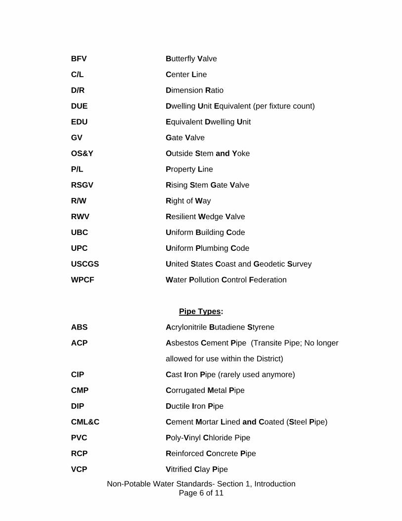
BFV Butterfly Valve
C/L Center Line
D/R Dimension Ratio
DUE Dwelling Unit Equivalent (per fixture count)
EDU Equivalent Dwelling Unit
GV Gate Valve
OS&Y Outside Stem and Yoke
P/L Property Line
RSGV Rising Stem Gate Valve
R/W Right of Way
RWV Resilient Wedge Valve
UBC Uniform Building Code
UPC Uniform Plumbing Code
USCGS United States Coast and Geodetic Survey
WPCF Water Pollution Control Federation
Pipe Types:
ABS Acrylonitrile Butadiene Styrene
ACP Asbestos Cement Pipe (Transite Pipe; No longer
allowed for use within the District)
CIP Cast Iron Pipe (rarely used anymore)
CMP Corrugated Metal Pipe
DIP Ductile Iron Pipe
CML&C Cement Mortar Lined and Coated (Steel Pipe)
PVC Poly-Vinyl Chloride Pipe
RCP Reinforced Concrete Pipe
VCP Vitrified Clay Pipe
Non-Potable Water Standards- Section 1, Introduction Page 6 of 11

DEFINITIONS "Approved" Unless specifically indicated, this shall mean the approval of
the General Manager, Camrosa Water District. “City” The City of Camarillo, California, and the various agencies
and departments thereof. In some cases “City” may mean Thousand Oaks or Moorpark.
"Contract" The contract includes the Notice Inviting Bids, Proposals,
Specifications, Agreements, Bonds and Plans. "Contractor" The individual, partnership, firm or corporation entering into
an agreement with the District, or with a developer to perform or execute the contemplated work.
"County" The County of Ventura, California, and the various agencies
and departments thereof. "Developer" An individual or organized group, partnership, corporation,
etc. proposing to subdivide or improve land, that will require water from the District.
"Developer's Engineer” The Engineer licensed by the State of California as a Civil
Engineer, employed by the developer, under whose direction, plans, profiles and details and cost estimates for the work are prepared and submitted to the District for review and approval.
"District" The Camrosa Water District or its authorized
representatives. "Easement" A recorded document in which the landowner gives the
District permanent or temporary rights to construct and maintain water mains and/or facilities across private property.
“Facility" Any conduit, structure, or feature used in the supply of water
or collection and distribution of sewage. "Field Acceptance" When the Inspector approved the physical installation of the
water system.
Non-Potable Water Standards- Section 1, Introduction Page 7 of 11

"Final Acceptance" When the Board approves both physical improvements, as well as the administrative items associated with the development.
"Fire Department" Ventura County Fire Department "Horizontal Separation” The least horizontal distance between the centerlines of
pipelines laid approximately parallel to one another at their closest point of approach and the least horizontal distance between the centerline of pipelines and the nearest edge of facilities.
"House Plumbing" Plumbing fixtures, devices, and drainage piping within a
building or structure. "Inspector" An employee or agent of the District engaged to observe and
record field compliance with design criteria, plans, and construction standards.
"Incremental Cost" The difference in cost between the pipelines and
appurtenances necessary to serve a particular development and the larger facility required by the District.
"Manager" Manager shall mean the General Manager of Camrosa
Water District, or the person engaged by the District and authorized to perform the duties assigned to the Manager, and shall include his/her Directors and representatives.
“Non-potable Water” Non-potable water is water that may contain objectionable
pollution, contamination, minerals, or bacterial agents and is considered unsafe and/or unpalatable for drinking.
“Offsite or Off-Tract” A water, sewer, or non-potable pipeline constructed beyond
tract boundaries and connecting with the District's system. "Or Approved Equal” The item referred to may be substituted for another item, if
this item is approved by the District for the particular use intended.
"Over-sizing Cost" The incremental cost of oversized water or sewer pipelines required by the District.
Non-Potable Water Standards- Section 1, Introduction Page 8 of 11

"Permit" Any written authorization required pursuant to any regulation of the District.
"Plans" The official drawings, profiles, or reproductions thereof,
approved by the District that shows the locations, characters, dimensions, and details of work to be done.
"Plate No." When not specified to the contrary, this refers to plates attached to these Standards.
"Pressure Zone" The zone within the District as defined by their elevations. “Reclaimed Water” Non-potable water that has been recovered from a surface
diversion or supply. “Recycled Water” Non-potable water that is the treated effluent from a
wastewater treatment facility. "Required" Unless otherwise indicated, this shall mean a requirement of
the District. "Required Fire Flow” A requirement established for each project, as determined
by the Ventura Fire Department using Insurance Services Office Guidelines.
"Service Line" Shall mean that portion of the horizontal piping beginning at
the water main and extending to its connection with the water meter.
"Sewer Line" Any conduit carrying "sewage" or "industrial waste" as
defined in Health and Safety Code Sections 5410(a) and 5410(b); any conduit carrying the effluent of treated sewage or industrial waste; or any conduit carrying agricultural waste or effluent of any treated agricultural waste including, but not limited to, interceptors, outfalls, and force mains.
"Tract Water Lines” The system of street water lines and service lines and other
appurtenances constructed by a developer within an approved tract.
"Vertical Separation” The difference in elevation between the outside bottom of
the higher pipe and the outside top of the lower pipe. "Water Line or Main” Any conduit carrying water that is 6” or larger and supplies
water to service lines, fire hydrants and other appurtenances.
Non-Potable Water Standards- Section 1, Introduction Page 9 of 11
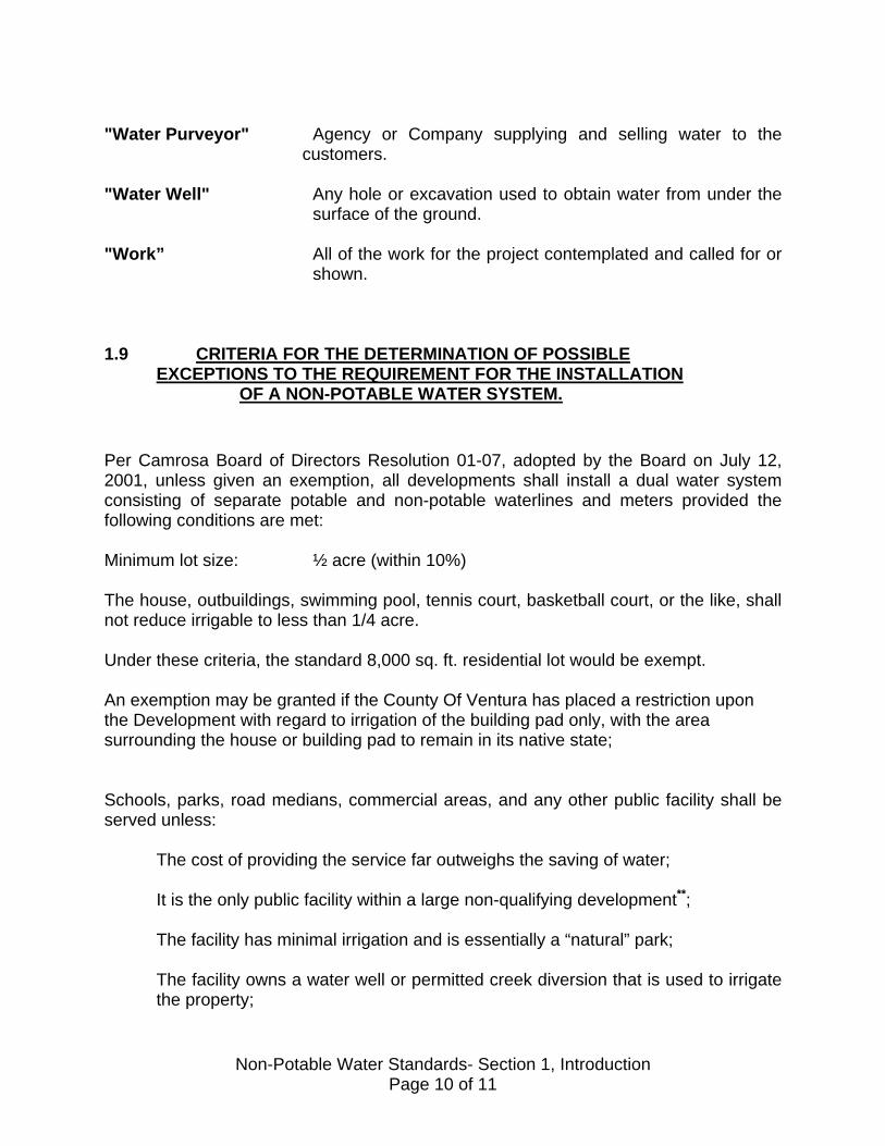
"Water Purveyor" Agency or Company supplying and selling water to the
customers. "Water Well" Any hole or excavation used to obtain water from under the
surface of the ground. "Work” All of the work for the project contemplated and called for or
shown. 1.9 CRITERIA FOR THE DETERMINATION OF POSSIBLE EXCEPTIONS TO THE REQUIREMENT FOR THE INSTALLATION OF A NON-POTABLE WATER SYSTEM.
Per Camrosa Board of Directors Resolution 01-07, adopted by the Board on July 12, 2001, unless given an exemption, all developments shall install a dual water system consisting of separate potable and non-potable waterlines and meters provided the following conditions are met: Minimum lot size: ½ acre (within 10%) The house, outbuildings, swimming pool, tennis court, basketball court, or the like, shall not reduce irrigable to less than 1/4 acre. Under these criteria, the standard 8,000 sq. ft. residential lot would be exempt. An exemption may be granted if the County Of Ventura has placed a restriction upon the Development with regard to irrigation of the building pad only, with the area surrounding the house or building pad to remain in its native state;
Schools, parks, road medians, commercial areas, and any other public facility shall be served unless: The cost of providing the service far outweighs the saving of water; It is the only public facility within a large non-qualifying development**; The facility has minimal irrigation and is essentially a “natural” park;
The facility owns a water well or permitted creek diversion that is used to irrigate the property;
Non-Potable Water Standards- Section 1, Introduction Page 10 of 11

The opinion of the General Manager is such that serving the facility or development would be of minimal benefit to the District and/or the customer.
Per Calleguas Municipal Water District regulations, each meter serving a parcel is liable for the assessment of connection fees. Generally a developer pays these fees as part of the development process and Camrosa is currently working with Calleguas to modify their requirement since the irrigation supply does not use any imported water within its system. The developer should assess whether it is necessary to provide two meters of the same size or to consider reducing the size of the potable meter since the vast majority of water used at a home is for outside irrigation. In addition the smaller domestic meter would reduce the capital connection fee assessed by Camrosa. Developers of non-qualifying tracts shall be assessed an in-lieu fee based upon ____% of the cost of installing a non-potable system within their development as a contribution to a fund for the expansion of the non-potable system into areas of benefit. A reasonable amount of landscaping necessary for the installation of a non-potable service would be ¼ acre when dealing with private residences and any size above 1/10th of an acre for public facilities. The Board of Directors may revisit from time to time the requirements of the Resolution and establish a 2-tiered capital fee structure for dealing with non-potable connection fees, particularly involving projects that are designed and financed by the District.
**If it is determined that providing service to the public facility would not be an unreasonable burden to the developer, each public facility shall have non-potable irrigation water service made available even if the surrounding development is exempt from the installation of a tract-wide dual system.
Non-Potable Water Standards- Section 1, Introduction Page 11 of 11

SECTION 2
DESIGN CRITERIA 2.1 CAMROSA WATER DISTRICT NON-POTABLE SYSTEM
A. GENERAL
Camrosa Water District is one of the four water purveyors within the City of Camarillo. The other three are the City of Camarillo, Pleasant Valley County Water District, and Crestview Mutual Water Company. Camrosa Water District’s service area generally includes the region east of Calleguas Creek, including the University of California, Channel Islands campus and portions of the Cities of Simi Valley, Moorpark and Thousand Oaks and unincorporated areas of Ventura County. The District should be consulted concerning the exact boundaries of its specific service area.
The District is the only purveyor currently providing non-potable water within the City of Camarillo. The District diverts surface water from the Conejo Creek, that otherwise goes to waste into the Pacific Ocean at Pt. Mugu, and pumps it into two (2) holding ponds and a Reservoir (1A) for storage and distribution. The District also operates wells, extracting ground water from the Santa Rosa Basin to provide service at the most economical cost to the customers.
B. INTERCONNECTION:
The District may require an interconnection between the potable and future non-potable water line in the following situations:
• The size of the parcel is such that the future parcel owner will need more volume that what the domestic meter can provide.
• Projected availability of the non-potable water is more than two years.
• It is more cost effective for the Developer to interconnect the two lines than installing a bigger domestic service and manifolding the domestic and the irrigation service.
• The Developer requests the interconnection. The District shall examine this request on a case- by- case basis. If the request has merit and will not have a negative impact on the normal and safe transmission of the potable water, the District shall approve such request.
If the non-potable water line becomes operational before the non-potable water becomes available, a backflow device on the irrigation service meter shall be required. The District shall determine the size of the backflow
Non-Potable Water Standards- Section 2, Design Criteria Page 1 of 17
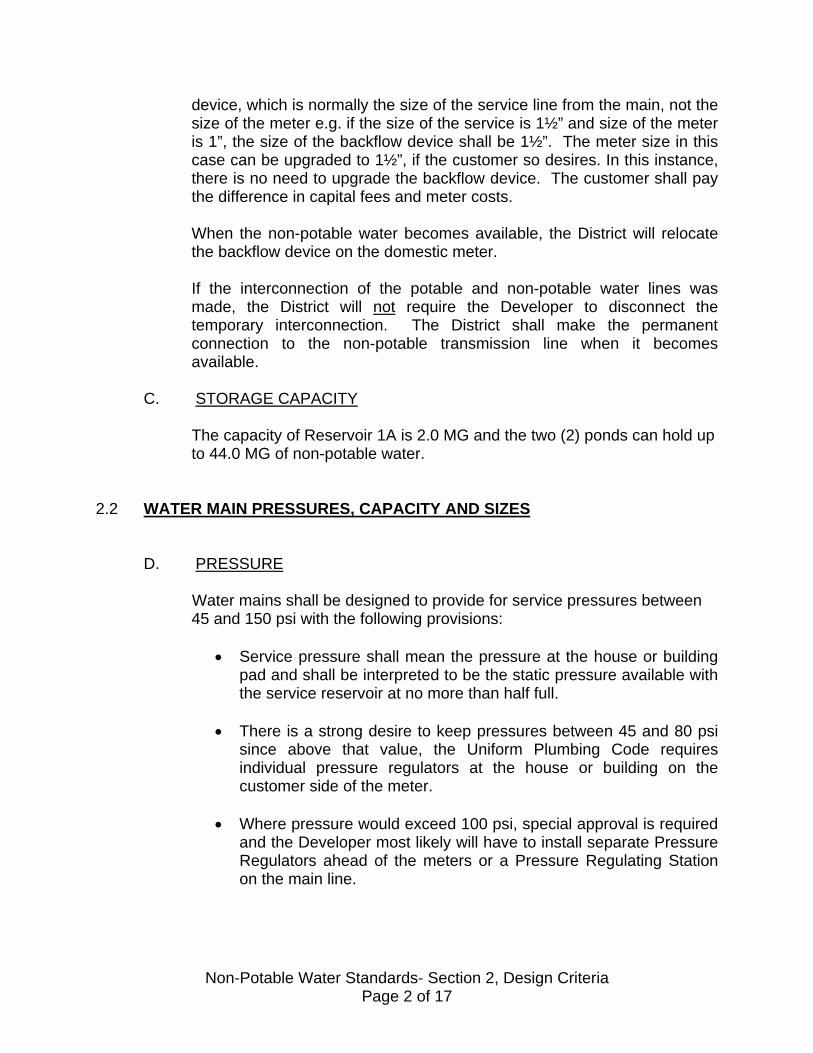
device, which is normally the size of the service line from the main, not the size of the meter e.g. if the size of the service is 1½” and size of the meter is 1”, the size of the backflow device shall be 1½”. The meter size in this case can be upgraded to 1½”, if the customer so desires. In this instance, there is no need to upgrade the backflow device. The customer shall pay the difference in capital fees and meter costs. When the non-potable water becomes available, the District will relocate the backflow device on the domestic meter. If the interconnection of the potable and non-potable water lines was made, the District will not require the Developer to disconnect the temporary interconnection. The District shall make the permanent connection to the non-potable transmission line when it becomes available.
C. STORAGE CAPACITY
The capacity of Reservoir 1A is 2.0 MG and the two (2) ponds can hold up to 44.0 MG of non-potable water.
2.2 WATER MAIN PRESSURES, CAPACITY AND SIZES
D. PRESSURE
Water mains shall be designed to provide for service pressures between 45 and 150 psi with the following provisions:
• Service pressure shall mean the pressure at the house or building
pad and shall be interpreted to be the static pressure available with the service reservoir at no more than half full.
• There is a strong desire to keep pressures between 45 and 80 psi
since above that value, the Uniform Plumbing Code requires individual pressure regulators at the house or building on the customer side of the meter.
• Where pressure would exceed 100 psi, special approval is required
and the Developer most likely will have to install separate Pressure Regulators ahead of the meters or a Pressure Regulating Station on the main line.
Non-Potable Water Standards- Section 2, Design Criteria Page 2 of 17
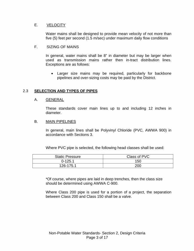
E. VELOCITY
Water mains shall be designed to provide mean velocity of not more than five (5) feet per second (1.5 m/sec) under maximum daily flow conditions
F. SIZING OF MAINS
In general, water mains shall be 8” in diameter but may be larger when used as transmission mains rather then in-tract distribution lines. Exceptions are as follows:
• Larger size mains may be required, particularly for backbone
pipelines and over-sizing costs may be paid by the District.
2.3 SELECTION AND TYPES OF PIPES
A. GENERAL
These standards cover main lines up to and including 12 inches in diameter.
B. MAIN PIPELINES
In general, main lines shall be Polyvinyl Chloride (PVC, AWWA 900) in accordance with Sections 3.
Where PVC pipe is selected, the following head classes shall be used:
Static Pressure Class of PVC 0-125.1 150
126-175.1 200
*Of course, where pipes are laid in deep trenches, then the class size should be determined using AWWA C-900.
Where Class 200 pipe is used for a portion of a project, the separation between Class 200 and Class 150 shall be a valve.
Non-Potable Water Standards- Section 2, Design Criteria Page 3 of 17

C. SERVICE LINES
These shall be 1-inch or larger except as described below. In the 1-inch size, type K copper is approved as described in Sections 3.5 and 7.10. The next larger size service shall be 1-1/2 inch which shall also be type K copper. Larger than 2- inch service lines shall be PVC, Ductile Iron or Steel pipes.
Service lines shall be capable of taking pressure up to the same level as the main line.
2.4 LOCATIONS OF LINES IN THE STREET
A. WATER MAINS
The non-potable water main centerline, wherever possible, shall be located in public streets parallel to and 9 to 12 feet south or east of the centerline on the same side of the street as the potable waterline. The standard separation between Potable and Non-Potable Waterlines is a minimum of 4 feet edge to edge horizontally and when crossing perpendicularly, the Non-Potable waterline must cross beneath the Potable waterline.
Where storm drains or other facilities are in the center of the street, the non-potable water lines shall be located to provide a minimum of 4 feet clearance between the outside of the pipe. This pertains as well to any case of paralleling lines. Special care is required where storm drains or other pipes cross above flexible pipes to avoid deflection problems when the other lines are installed.
When an area outside the tract or development can be logically served by extending the non-potable water main in future streets or easements, the pipeline shall be extended to the tract or project boundary or to the end of a paved street in a manner facilitating future extensions.
B. CRITERIA FOR SEPARATION OF NON-POTABLE WATER AND POTABLE WATER MAINS
1. General:
Proper separation of potable and non-potable water systems is necessary to reduce the potential for an outbreak of waterborne diseases. Non-potable water lines may leak and saturate the surrounding soil. This is caused primarily by structural failure of the line or improperly encasing the conduit. A potential public health hazard exists when the potable water mains are depressurized and
Non-Potable Water Standards- Section 2, Design Criteria Page 4 of 17
no pressure or negative pressures occur. The hazard is further compounded when, in the course of installing or repairing a potable water main, existing non-potable water enters into the water main. Additionally, if a potable water main fails in close proximity to a non-potable water line, the resultant failure may disturb the bedding of the line and cause it to fail. In the event of an earthquake or man-made disaster, simultaneous failure of both conduits often occurs. The discussion below is excerpted from the criteria established by the Department of Health Services, State of California, Health and Welfare Agency.
2. Basic Separation Standards:
• Parallel Construction
The Horizontal distance between pressure potable water mains and non-potable lines shall be at least 4 feet.
• Perpendicular Construction (Crossing)
Pressure potable water mains shall be at least one foot above non-potable lines where these lines must cross.
• Common Trench
Potable water mains and non-potable water lines must not be installed in the same trench. When potable water mains and non-potable water mains are not adequately separated, the potential for contamination of the potable water supply increases. Therefore, when adequate physical separation cannot be attained, increasing the structural integrity of both the pipe materials and joints should provide an increase in the factor of safety.
3. Exceptions to Basic Separation Standards:
Local conditions such as available space, limited slope, existing structure, etc., may create a situation where there is no alternative but to install potable water mains or non-potable lines at a distance less than required by the Basic Separation Standards. In such cases, alternative construction criteria may be allowed in very special circumstances. Details shall be submitted to Camrosa Engineering Department for approval prior to construction.
Non-Potable Water Standards- Section 2, Design Criteria Page 5 of 17

4. Special Provisions:
• Basic Separation Standards are applicable under normal conditions for non-potable lines and potable water distribution mains.
• The Engineer and/or the District may determine more stringent
requirements.
• In the installation of potable water mains or non-potable lines, measures should be taken to prevent or minimize disturbances of the existing line. Disturbance of the supporting base of this line could eventually result in failure of this existing pipeline.
2.5 LOCATIONS OF LINES (EASEMENTS)
Easements should be avoided where a reasonable alternate solution exists. Unless there are either physical limitations or extreme economic penalties, non-potable water lines should be installed within streets. When easements are required, there shall be careful consideration of how the line is to be maintained and/or replaced, if necessary. Where easements are necessary and where the slope (perpendicular to the pipe) exceeds 25 percent (1 vertical to 4 horizontal) then the plans shall clearly indicate appropriate contours within the easement.
In general, the line within the easement shall be accessible by conventional maintenance vehicles traveling over paved roads or driveways unless otherwise approved. Service lines should be connected to a main line within an easement unless specifically approved.
A. Width:
Non-potable water easements for pipes up to 12 inches in diameter should normally be a minimum of 10 feet wide. However, additional easement width shall be required where the depths of pipe are excessive or where deemed necessary. The plans should clearly indicate any known block walls, pavements, trees or other obstructions within a proposed easement. Such items are contrary to the Districts policy and require special approval. Included with such approval may be monetary obligation towards the operation and maintenance of the non-potable water line within the easement; also, the “As-Built” drawings shall indicate such approval and such installations.
Non-Potable Water Standards- Section 2, Design Criteria Page 6 of 17
B. Pipeline Location:
Pipelines shall generally be placed in the center of easements; only in unusual circumstances will a line be approved that is closer than 5 feet from the easement edge. Unless specifically otherwise approved, the line shall be straight without horizontal bends or deflections.
C. Easement Location:
The full easement width shall be on one lot or property in such a manner that walls, trees or permanent improvements will not obstruct access to the pipeline. Where this requirement cannot be met without interfering with the existing buildings, easements may straddle lot lines providing special approval is received and the non-potable water pipeline is not located on the lot lines
D. Deeds
Deeds for easements shall provide for restrictions of permanent construction with easement to provide ingress and egress for maintenance.
E. Easement Provisions:
Easements shall be provided as follows:
1. For Subdivisions:
The Owner of the land included within the subdivision shall offer to dedicate, for public use, the non-potable water easements so designated on the final map. Standard language is included in Section 4.10.
2. For Other Than Subdivisions:
Dedication of non-potable water rights-of -way shall occur by means of deeds of conveyance to the District for all dedications other than those dedications created by subdivision tract maps on a form and as approved.
Non-Potable Water Standards- Section 2, Design Criteria Page 7 of 17

2.6 DEPTH OF NON-POTABLE WATER MAINS
The standard minimum depth of cover to the top of the pipe shall be 36-inches for pipes up to 10-inch in diameter and 42 inches for 12-inch or larger.
In achieving the above depths, it must be recognized that numerous grade changes to achieve 36-inch or 42-inch depths of cover are not desirable and the designer shall blend the requirement for a reasonable straight pipeline with those for a relatively uniform depth.
Increases in depth may be required where future road improvements could potentially remove some of the existing cover or where there are other conflicting utilities. Pipelines placed in open, unpaved terrain shall generally have a minimum cover of 42-inches.
2.7 LOCATION AND SIZE OF VALVES
Valves shall be located at locations allowing for the isolation of particular pipe segments in the event repairs or replacements are needed. Longer reaches of pipelines shall require an in-line valve at intervals of no more than 1,500 feet except for lines 8” or larger, where valves shall be at intervals no greater than 1,000 feet.
All pipeline valves shall generally be the same nominal size as the pipeline.
2.8 AIR AND VACUUM ASSEMBLIES
A. TYPES OF VALVES
1. Air release valves allow the discharge of air that accumulates at high points along the pipeline. The air is entrained in the water and when it accumulates at the high points, it creates throttling effect, as would a partially closed valve.
2. Air and vacuum valves allow large quantities of air to be expelled
during filling and allow air to re-enter the pipeline during draining of the pipeline whether planned or due to rupture. These valves are located at high points along the line.
3. “Combination Air Release Valves” combine both the air release and air
& vacuum valves described above and it is this type of valve that is generally specified in the District’s system.
Non-Potable Water Standards- Section 2, Design Criteria Page 8 of 17

B. LOCATION:
Combination air release valves shall be located at all significant high points along the pipeline as approved or required by the District.
C. SIZING:
In order to somewhat simplify the selection of the combination of air release valves, the following is provided as guidelines for determining the size: 1. Determine the maximum rate of flow that can occur in the line:
Rate in CFS = GPM under filling conditions 7 x 60 Rate in CFS = 0.087 (SD5) ½ under draining conditions S = Slope or gradient (ft. per second) D = Diameter of pipe in inches
2. Using the value in “1” above, the size should be:
CFS Rate Valve Size 0-5 1”
5-15 2”
3. For most installation involving 6-inch pipelines, the valve will be 1” size. Plate W-33 illustrates typical installations.
2.9 BLOW-OFF ASSEMBLIES
A. GENERAL:
Blow-off assemblies are placed at low spots in the line to facilitate line draining and to allow the removal of sediments that accumulate in low areas of the pipeline.
Plate W-31 shows 2- inch.
B. SIZING:
Blow-offs should be sized according to the following criteria:
Non-Potable Water Standards- Section 2, Design Criteria Page 9 of 17
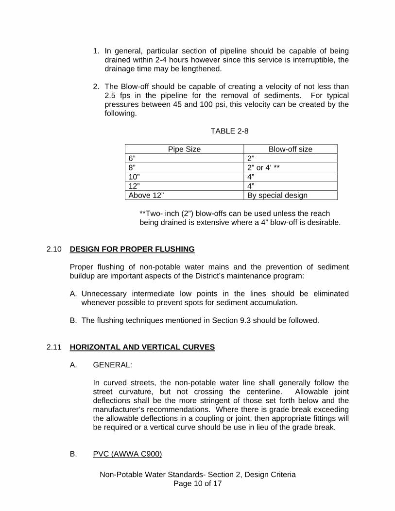
1. In general, particular section of pipeline should be capable of being drained within 2-4 hours however since this service is interruptible, the drainage time may be lengthened.
2. The Blow-off should be capable of creating a velocity of not less than
2.5 fps in the pipeline for the removal of sediments. For typical pressures between 45 and 100 psi, this velocity can be created by the following.
TABLE 2-8
Pipe Size Blow-off size
6” 2” 8” 2” or 4’ ** 10” 4” 12” 4” Above 12” By special design
**Two- inch (2”) blow-offs can be used unless the reach being drained is extensive where a 4” blow-off is desirable.
2.10 DESIGN FOR PROPER FLUSHING
Proper flushing of non-potable water mains and the prevention of sediment buildup are important aspects of the District’s maintenance program: A. Unnecessary intermediate low points in the lines should be eliminated
whenever possible to prevent spots for sediment accumulation. B. The flushing techniques mentioned in Section 9.3 should be followed.
2.11 HORIZONTAL AND VERTICAL CURVES
A. GENERAL:
In curved streets, the non-potable water line shall generally follow the street curvature, but not crossing the centerline. Allowable joint deflections shall be the more stringent of those set forth below and the manufacturer’s recommendations. Where there is grade break exceeding the allowable deflections in a coupling or joint, then appropriate fittings will be required or a vertical curve should be use in lieu of the grade break.
B. PVC (AWWA C900)
Non-Potable Water Standards- Section 2, Design Criteria Page 10 of 17
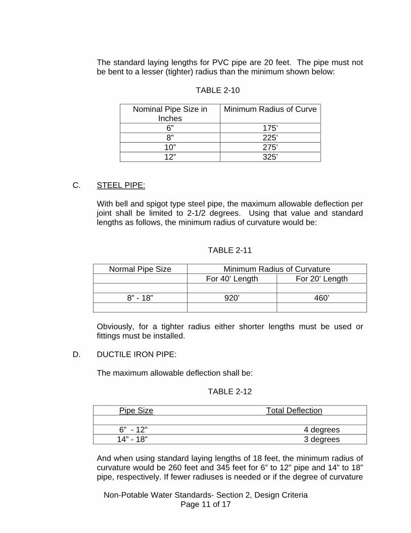
The standard laying lengths for PVC pipe are 20 feet. The pipe must not be bent to a lesser (tighter) radius than the minimum shown below:
TABLE 2-10
Nominal Pipe Size in Inches
Minimum Radius of Curve
6” 175’ 8” 225’ 10” 275’ 12” 325’
C. STEEL PIPE:
With bell and spigot type steel pipe, the maximum allowable deflection per joint shall be limited to 2-1/2 degrees. Using that value and standard lengths as follows, the minimum radius of curvature would be:
TABLE 2-11
Normal Pipe Size Minimum Radius of Curvature For 40’ Length For 20’ Length
8” - 18” 920’ 460’
Obviously, for a tighter radius either shorter lengths must be used or fittings must be installed.
D. DUCTILE IRON PIPE:
The maximum allowable deflection shall be:
TABLE 2-12
Pipe Size Total Deflection 6” - 12” 4 degrees 14” - 18” 3 degrees
And when using standard laying lengths of 18 feet, the minimum radius of curvature would be 260 feet and 345 feet for 6” to 12” pipe and 14” to 18” pipe, respectively. If fewer radiuses is needed or if the degree of curvature
Non-Potable Water Standards- Section 2, Design Criteria Page 11 of 17
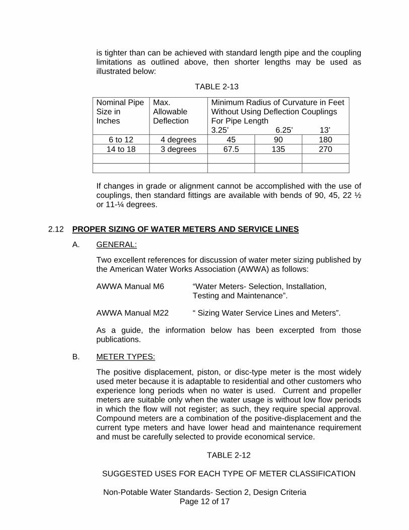
is tighter than can be achieved with standard length pipe and the coupling limitations as outlined above, then shorter lengths may be used as illustrated below:
TABLE 2-13
Nominal Pipe Size in Inches
Max. Allowable Deflection
Minimum Radius of Curvature in Feet Without Using Deflection Couplings For Pipe Length 3.25’ 6.25’ 13’
6 to 12 4 degrees 45 90 180 14 to 18 3 degrees 67.5 135 270
If changes in grade or alignment cannot be accomplished with the use of couplings, then standard fittings are available with bends of 90, 45, 22 ½ or 11-¼ degrees.
2.12 PROPER SIZING OF WATER METERS AND SERVICE LINES
A. GENERAL:
Two excellent references for discussion of water meter sizing published by the American Water Works Association (AWWA) as follows: AWWA Manual M6 “Water Meters- Selection, Installation, Testing and Maintenance”. AWWA Manual M22 “ Sizing Water Service Lines and Meters”. As a guide, the information below has been excerpted from those publications.
B. METER TYPES:
The positive displacement, piston, or disc-type meter is the most widely used meter because it is adaptable to residential and other customers who experience long periods when no water is used. Current and propeller meters are suitable only when the water usage is without low flow periods in which the flow will not register; as such, they require special approval. Compound meters are a combination of the positive-displacement and the current type meters and have lower head and maintenance requirement and must be carefully selected to provide economical service.
TABLE 2-12
SUGGESTED USES FOR EACH TYPE OF METER CLASSIFICATION
Non-Potable Water Standards- Section 2, Design Criteria Page 12 of 17

Meter Type Suggested Use
Positive-displacement meters ¾” to 2”
Customer with normal irrigation demands. Residential, small to medium apartments
Turbine Meter (strainer required) 2” – 12”
Small to large landscaping and/or agricultural demands
C. Meter Sizing:
Water meters are designed to deliver a maximum flow for short periods of time with a lower flow capacity for sustained usage without damage or above normal wear occurring to the meter. The selection of the type and size of the meter should be based only on the flow requirement and the type of use- not on the pressure loss through the meter. If there is a known expansion program or increased meter usage can be anticipated in the future, then provision should be made for larger facilities in the future. When this occurs, the meter should be installed for the needs at the time but also with a meter box and connections that are adequate for future requirements. It should be remembered that the District would select the meter type; however, as a guide in determining the meter size, Table 2-13 can be used. Notes for that Table include: 1. AWWA recommends that the continuous flow service in the meter not
exceed 30% of the maximum capacity. 2. AWWA further recommended that for design purposes the maximum
capacity be valued at 80% of the rated capacity.
TABLE 2-13
Non-Potable Water Standards- Section 2, Design Criteria Page 13 of 17

Service Line
Application Meter Size
Meter Description
Low Flow GPM*
Normal Flow Range GPM
Maximum Rating GPM
2” Irrigation 1-1/2” Positive Displacement
1.5 5-50 100
2” Irrigation 2” Positive Displacement
2 8-80 160
2” Irrigation 2” Turbo 3 4-160 200 4” Irrigation 3” Turbo 4 5-350 450 4” Irrigation 4” Turbo 10 15-
1,000 1,250
Notes:
i. * At 95% accuracy
Pressure losses through the meters may be illustrated as follows:
TABLE 2-14
METER TYPE PRESSURE LOSS (PSI) @ DESIGNATED FLOW 30% OF MAX. CAPACITY 80 % OF MAX. CAPACITY
Displacement 0.5 - 1.1 6.3 – 8.6 Turbo 0.7 – 1.2 2.0 – 3.0 The sizing of the meter is dependent upon the correct establishment of a maximum flow rate. In this regard, Chapter 4 of AWWA Manual No.22 can be consulted. In general, the meter should not be oversized and for all but residential or small commercial structures, the Developer’s Engineer should check such items as fixture units and landscape irrigation in arriving at the proper meter size.
D. SERVICE LINE SIZING
Proper service line sizing is a function of the maximum anticipated flow rates and the allowable pressure loss for adequate pressure. If pressure is questionable or if flows are anticipated to increase in the future, it is better to oversize the service line than to oversize the meter. As a guideline for the smaller installations the following service lines should be used with the respective meters:
TABLE 2-15
Non-Potable Water Standards- Section 2, Design Criteria Page 14 of 17
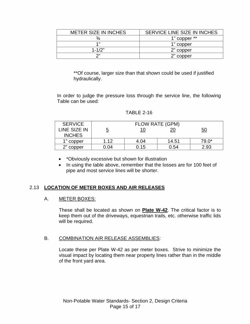
METER SIZE IN INCHES SERVICE LINE SIZE IN INCHES ¾ 1” copper ** 1” 1” copper
1-1/2” 2” copper 2” 2” copper
**Of course, larger size than that shown could be used if justified hydraulically.
In order to judge the pressure loss through the service line, the following Table can be used:
TABLE 2-16
SERVICE LINE SIZE IN
INCHES
FLOW RATE (GPM) 5 10 20 50
1” copper 1.12 4.04 14.51 79.0* 2” copper 0.04 0.15 0.54 2.93
• *Obviously excessive but shown for illustration • In using the table above, remember that the losses are for 100 feet of
pipe and most service lines will be shorter. 2.13 LOCATION OF METER BOXES AND AIR RELEASES
A. METER BOXES:
These shall be located as shown on Plate W-42. The critical factor is to keep them out of the driveways, equestrian trails, etc. otherwise traffic lids will be required.
B. COMBINATION AIR RELEASE ASSEMBLIES:
Locate these per Plate W-42 as per meter boxes. Strive to minimize the visual impact by locating them near property lines rather than in the middle of the front yard area.
Non-Potable Water Standards- Section 2, Design Criteria Page 15 of 17

C. POLICY ON IRRIGATION METERS:
Where the parkways or side landscaping strips along the streets are to be irrigated, a separate meter must be installed on each side of the street. In such cases, running an irrigation line from the meter to the other side of the street is not allowed.
Where a median strip must be irrigated, the meter may either be in the side parkway or in the median strip, providing that at either location, the meter is easily accessible and protected from being covered by landscape materials or other obstructions. The District reserves the right to select all meter locations.
2.14 STRUCTURAL REQUIREMENTS
A. UNDER ROADS:
All structures and pipe placed under public roads shall be of sufficient strength to support with an adequate factor of safety for the backfill, road surfacing and H-20 loading per AASHTO Standard Specifications (truck loading with impact). The City or County who has jurisdiction over the project area may specify higher loading.
B. OTHER PIPES AND STRUCTURES:
Non-potable water lines designed to cross under or over other pipes or structures shall be protected from damage and shall be constructed to prevent endangering the other pipe or structure. In this regard, particular attention should be given to the possibility and prevention of settlement-cause damage. Also, where future replacement of any line may be extremely difficult due to the pipe or structure, special design consideration may be required. Any of the plates, that detail various encasements or other protection, may be required in such instances.
C. FLEXIBLE JOINTS:
Flexible joints that will allow for different settlements or other movement of non-potable water pipe lines or structures, adjacent pipe and adjacent structures shall be provided where non-potable water lines enter encasements or other structures. Flexible joints shall be within a minimum of 24” of such structures unless otherwise approved.
Non-Potable Water Standards- Section 2, Design Criteria Page 16 of 17
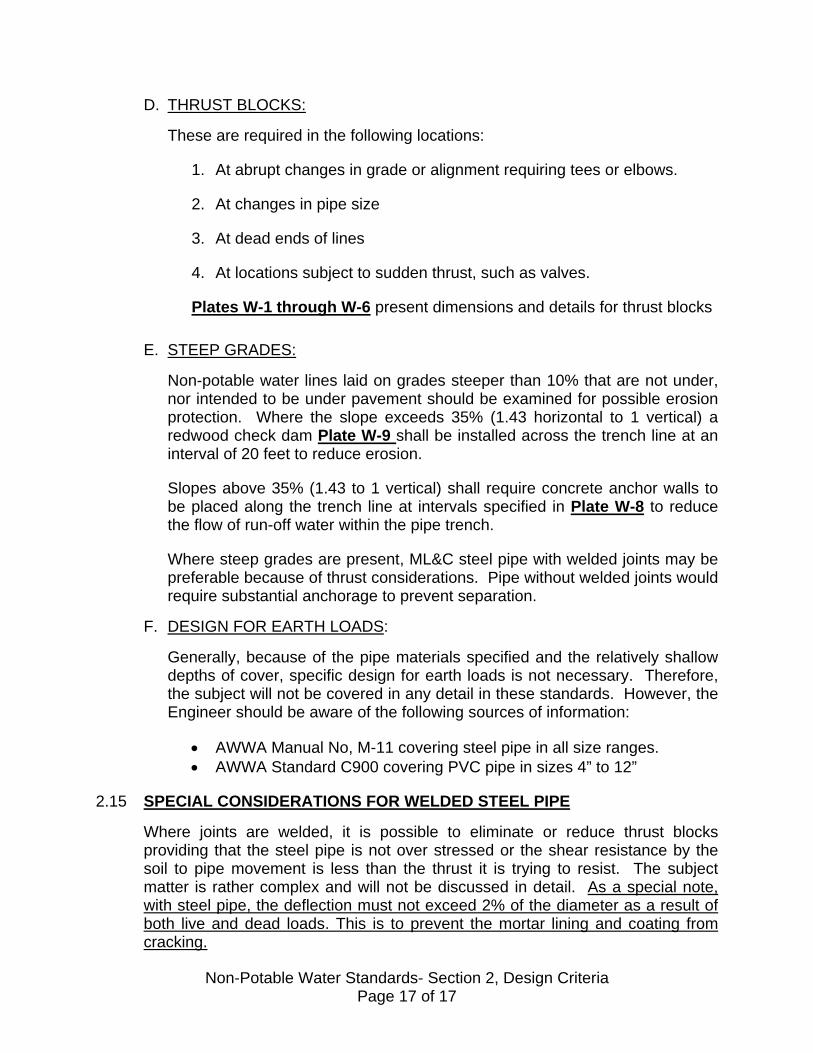
D. THRUST BLOCKS:
These are required in the following locations:
1. At abrupt changes in grade or alignment requiring tees or elbows. 2. At changes in pipe size
3. At dead ends of lines
4. At locations subject to sudden thrust, such as valves.
Plates W-1 through W-6 present dimensions and details for thrust blocks
E. STEEP GRADES:
Non-potable water lines laid on grades steeper than 10% that are not under, nor intended to be under pavement should be examined for possible erosion protection. Where the slope exceeds 35% (1.43 horizontal to 1 vertical) a redwood check dam Plate W-9 shall be installed across the trench line at an interval of 20 feet to reduce erosion. Slopes above 35% (1.43 to 1 vertical) shall require concrete anchor walls to be placed along the trench line at intervals specified in Plate W-8 to reduce the flow of run-off water within the pipe trench. Where steep grades are present, ML&C steel pipe with welded joints may be preferable because of thrust considerations. Pipe without welded joints would require substantial anchorage to prevent separation.
F. DESIGN FOR EARTH LOADS:
Generally, because of the pipe materials specified and the relatively shallow depths of cover, specific design for earth loads is not necessary. Therefore, the subject will not be covered in any detail in these standards. However, the Engineer should be aware of the following sources of information:
• AWWA Manual No, M-11 covering steel pipe in all size ranges. • AWWA Standard C900 covering PVC pipe in sizes 4” to 12”
2.15 SPECIAL CONSIDERATIONS FOR WELDED STEEL PIPE
Where joints are welded, it is possible to eliminate or reduce thrust blocks providing that the steel pipe is not over stressed or the shear resistance by the soil to pipe movement is less than the thrust it is trying to resist. The subject matter is rather complex and will not be discussed in detail. As a special note, with steel pipe, the deflection must not exceed 2% of the diameter as a result of both live and dead loads. This is to prevent the mortar lining and coating from cracking.
Non-Potable Water Standards- Section 2, Design Criteria Page 17 of 17
SECTION 3.0
MATERIALS 3.1 GENERAL REQUIREMENTS
This section discusses the materials involved in non-potable water pipeline systems and associated construction activities. The materials selected have been chosen for their strength, durability and ease of maintenance. All materials, unless specifically approved otherwise, shall be new and unused. Where applicable, American Water Works Association (AWWA) or other standards have been referenced and it shall be the responsibility of the Developer/Engineer/Contractor to be familiar with those standards to ensure compliance. Titles corresponding to the specific numbers are given in the reference section of the standards. In some instances, particular manufacturers and product names have been mentioned as being approved. Other products may also meet the requirements, but must first be approved in writing by the District. One factor, that may be considered by the District in any consideration of other products, is the need for some degree of standardization. If at any time the District believes that the use of a specific product must either be halted or changed, the District has the authority to make the change providing the decision is based upon an engineering, performance or maintenance evaluation.
3.2 TESTING AND ACCEPTABILITY OF MATERIAL
The District shall require such tests and certifications as deemed necessary to show that the specified materials have been employed. Notwithstanding prior factory or yard inspections, the District shall have the right to reject any damaged or defective materials found on the job that will affect the durability or performance of the installation and other its removal from site.
3.3 MAIN LINE PIPE MATERIALS
Generally accepted main line pipe materials consists of either polyvinyl chloride (PVC), steel (ML &C) or ductile iron pipe (DIP) as described in this section. A. General. All pipe used in the construction of Reclaimed or non-potable
waterlines shall be marked as such by one the following methods:
Non-Potable Water Standards- Section 3, Materials Page 1 of 21

PVC pipe shall be purple in color either by being manufactured in that color or encased, during construction, in a tubular purple sleeve that completely surrounds the pipe and is marked “Reclaimed Water”. Steel and Ductile pipe shall be installed using the purple sleeve mentioned above.
B. PVC PIPE:
1. Pipe.
PVC pipe shall be purple in color, or be installed with a purple sleeve marked “Reclaimed Water” the entire length of the pipeline, shall conform to the quality and strength requirements of AWWA C900 that covers PVC pipe in sizes 4” –12”. Each standard or random length of pipe shall be clearly marked with the following:
• For Reclaimed Water Use • Nominal size and O.D. base, i.e. 6” cast iron pipe size • Material code “PVC 1120” • AWWA pressure class i.e. PC150 • AWWA designation “AWWA C900” • Manufacturer’s trade name and production record code. • Seal (mark) of testing agency The standard laying length shall be 20 feet (plus/minus) 1 inch in all classes and sizes. A maximum, of 15 percent may be furnished in random lengths of not less than 10 feet each. AWWA C900 pipe has the same outside (O.D.) as that of a Ductile Iron pipe (D.I.P.O.D.) in the sizes furnished. One gasket shall be furnished with each length of elastomeric-gasket bell-end pipe and two gaskets shall be furnished with each coupling where couplings are used. Pipe surfaces shall be free from nicks, scratches and other blemishes. The joining surfaces of pipe spigots and of integral bell and sleeve reinforced bell sockets shall be free from gouges or other imperfections that might cause leakage. Two trade names, that are approved, are Certainteed “Vinyl Iron Pipe” and Johns Manville’s “Blue Brute Pipe” or approved equal.
2. Joint Mechanisms:
The joints shall be either of the following:
Non-Potable Water Standards- Section 3, Materials Page 2 of 21
• Integral wall- thickened bell end (bell and spigot with rubber gasket).
• Integral sleeve reinforced bell end. • Elastomeric gasket couplings.
PVC solvent cement joints, although allowed by AWWA C900 are not approved for use in the District.
3. Couplings and Fittings:
Where couplings are used, they shall meet the requirements of AWWA C900. Couplings shall be as furnished by the manufacturers. Couplings shall be marked with the same information as the pipe. Cast Iron fittings can be used with PVC pipe and these are discussed in Section 3-4.
4. Physical Test Requirements.
Hydrostatic, burst, and sustained pressure and crushing tests shall be conducted at the factory in accordance with AWWA C400. All testing shall be done by a recognized testing laboratory with such testing available for inspection by the District. If required, the manufacturer shall supply a letter of certification attesting to their pipe meeting these specifications.
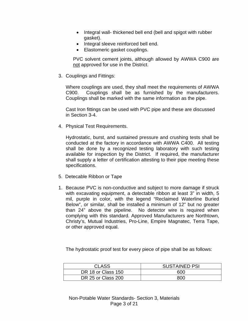
5. Detecable Ribbon or Tape
1. Because PVC is non-conductive and subject to more damage if struck with excavating equipment, a detectable ribbon at least 3” in width, 5 mil, purple in color, with the legend “Reclaimed Waterline Buried Below”, or similar, shall be installed a minimum of 12” but no greater than 24” above the pipeline. No detector wire is required when complying with this standard. Approved Manufacturers are Northtown, Christy’s, Mutual Industries, Pro-Line, Empire Magnatec, Terra Tape, or other approved equal. The hydrostatic proof test for every piece of pipe shall be as follows:
CLASS SUSTAINED PSI
DR 18 or Class 150 600 DR 25 or Class 200 800
Non-Potable Water Standards- Section 3, Materials Page 3 of 21

C. STEEL PIPE:
1. Pipe.
Steel pipe shall conform to the quality and strength requirements of AWWA C200 or as specified below. That standard pertains to electrically butt-welded straight-seam or spiral-seam pipe and to seamless pipe 6” in diameter or larger. The steel shall conform to one of the following:
TABLE 3-2
Specification Grade Minimum Yield Point (psi)
ASTM A238 C 30,000 D 33,000
ASTM A570 30 30,000 36 36,000 40 40,000 45 45,000
The stress in the steel pipe shall not exceed the higher of 15,000 psi or one-half the designated working pressure except that the following minimum thickness shall be used:
TABLE 3-3
Normal Inside Diameter Inches
Minimum Thickness Inches
Maximum Pressure* For Thickness
Specified PSI
8” 0.105 394 10” 0.135 405 12” 0.135 338 14” 0.135 389 16” 0.135 253 18” 0.179 298
The gages specified above consider the thickness required for welding as well as that required for external loads and a corrosion allowance.
Non-Potable Water Standards- Section 3, Materials Page 4 of 21
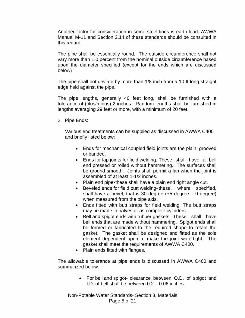
Another factor for consideration in some steel lines is earth-load. AWWA Manual M-11 and Section 2.14 of these standards should be consulted in this regard. The pipe shall be essentially round. The outside circumference shall not vary more than 1.0 percent from the nominal outside circumference based upon the diameter specified (except for the ends which are discussed below) The pipe shall not deviate by more than 1/8 inch from a 10 ft long straight edge held against the pipe. The pipe lengths, generally 40 feet long, shall be furnished with a tolerance of (plus/minus) 2 inches. Random lengths shall be furnished in lengths averaging 29 feet or more, with a minimum of 20 feet. 2. Pipe Ends:
Various end treatments can be supplied as discussed in AWWA C400 and briefly listed below:
• Ends for mechanical coupled field joints are the plain, grooved or banded.
• Ends for lap joints for field welding. These shall have a bell end pressed or rolled without hammering. The surfaces shall be ground smooth. Joints shall permit a lap when the joint is assembled of at least 1-1/2 inches.
• Plain end pipe- these shall have a plain end right angle cut. • Beveled ends for field butt welding- these, where specified,
shall have a bevel, that is 30 degree (+5 degree – 0 degree) when measured from the pipe axis.
• Ends fitted with butt straps for field welding. The butt straps may be made in halves or as complete cylinders.
• Bell and spigot ends with rubber gaskets. These shall have bell ends that are made without hammering. Spigot ends shall be formed or fabricated to the required shape to retain the gasket. The gasket shall be designed and fitted as the sole element dependent upon to make the joint watertight. The gasket shall meet the requirements of AWWA C400.
• Plain ends fitted with flanges.
The allowable tolerance at pipe ends is discussed in AWWA C400 and summarized below:
• For bell and spigot- clearance between O.D. of spigot and I.D. of bell shall be between 0.2 – 0.06 inches.
Non-Potable Water Standards- Section 3, Materials Page 5 of 21

• For lap joint- I.D. of bell shall be 1/32 - 3/16 inches greater
than O.D. of spigot.
• For plain ends (incl. beveled or butt straps or flanges) – O.D. within 4 inches of end shall be –1/16 inch or + 1/8 inch from specified O.D.
3. Hydrostatic Tests:
Each pipe shall be tested by the manufacturer to a pressure not less than that determined by: P = 2ST D Where S = 0.75 times the minimum yield strength of the steel and other items are as discussed earlier.
4. Mortar Lining and Coating (ML &C):
Unless otherwise approved or as revised below, all steel pipes shall be mortar lined and coated in accordance with AWWA C205, which covers shop applied lining, and the lining holdback shall be as specified for the particular type of joint.
TABLE 3-4
CEMENT MORTAR LINING THICKNESSES
NORMAL PIPE SIZES
INCHES
LINING THICKNESS INCHES
TOLERANCE INCHES
6”-10” 5/16 -1/16 + 1/8 12” 16” 3/8 -1/16 + 1/8
18” ½ -1/16 + 1/8
It should be noted that the District requirements for thickness exceed those of the AWWA standard. Also, it should be noted that no wire
Non-Potable Water Standards- Section 3, Materials Page 6 of 21

fabric reinforcement is required for any lining of specials less than 24-inches in diameter.
5. Mortar Lining:
Cement mortar lining shall be uniform in thickness except at joints or other discontinuities. Ends of lining shall be left square and uniform and the lining holdback shall be as specified for the particular type of joint.
TABLE 3-5
CEMENT MORTAR COATING THICKNESS
Normal Pipe Size Inches
Coating Thickness Inches
Tolerance Inches
6” – 10” ½ -0 + 1/8 12” – 16” ¾ -0 + 1/8
18” 1 -0 + 1/8
It should be noted that the District’s requirements exceed those of the AWWA standard. Reinforcement for the coating of pipe section shall be one of the following as specified by the supplier:
• Spiral wire - 15 gage @ max. 1-1/4 in. spacing with wire meeting ASTM A82
• Wire fabric - 2 x 4 steel wire mesh, 13 gage each way meeting ASTM A185
• Ribbon mesh - 1 x 1 mesh of 18 gage wire or 1- ½ x 1- ½ mesh of 17 gage wire, all meeting ASTM A82
6. Field Joints:
The materials and construction methods for field joints shall be as discussed in Section 7.
7. Electrically Bonded Connections.
Two metal jumper rods are required to form an electrically bonded connection between all steel pipe joints that are not welded, except at insulating couplings called for on the plans.
Non-Potable Water Standards- Section 3, Materials Page 7 of 21

The jumper rods shall be either 3/8” diameter rods or ¼ “ x ½” bars. They shall be at least 7 inches long with an offset of ¼ inch in the middle 3 inches. No welding shall take place in the middle 3-inch section.
8. Welded Joints:
One of each section shall be swaged out to form a female or bell which shall permit the male or spigot end to enter approximately one-inch with a clearance of approximately 1/32-inch. The spigot end shall be “sized” to permit it to enter the bell end of the adjacent section and the weld bead shall be ground flush for the distance it is to enter the bell end.
9. Butt Strap Closures:
The butt straps shall be the same thickness as the pipe wall but not less than 10 gage, at least 10 inches wide and rolled to fit the outside cylinder diameter, and shall be centered over the ends of the pipe sections they are to join. A standard 5-inch pipe half coupling shall be shop welded to the top section of the butt strap to permit access for mortar lining the inside of the joint. The coupling shall be sealed with a standard 5-inch plug field welded to the coupling.
D. Ductile Iron Pipe
1. Pipe:
The pipe shall conform to AWWA C151 for both quality and strength. Each pipe shall include the letters “DI” or word “DUCTILE” to indicate the pipe material.
2. Joints:
These shall be of the rubber gasket push-on joint type conforming to the requirements of AWWA C111 and being the “TYTON” type.
3. Fittings:
All fittings shall conform to AWWA C110.
4. Lining and Coating:
Unless otherwise approved, the internal surfaces shall be lined with a uniform thickness of cement mortar and then sealed with a bituminous coating in accordance with AWWA C104.
Non-Potable Water Standards- Section 3, Materials Page 8 of 21

5. Encasement:
The outside surface shall be protected with polyethylene encasement furnished and installed in accordance with AWWA C105.
3.4 MAIN LINE FITTINGS
A. Ductile Iron Fittings:
These fittings shall meet the requirements of AWWA C110. All fittings shall be rated for 250 PSI. This standard covers all but is not limited to fittings with combination of ends including mechanical joints, plain end, flange, push joint. The fitting types are as follows: 90 degree bend, 45-degree bend, 22-1/2 bend, 11-1/4 bend. Tees and crosses, reducers, caps and plugs, connecting pieces, flanged bends, flanged tees and crosses, flanged reducers. Ductile –iron compact fittings, per AWWA C153, are allowed. It should be understood that care must be exercised to not mix mechanical and flange joint ends since they will not mate. Section B discusses flange requirements.
B. Flanges, Bolts and Gaskets:
They shall be flat-faced and meet the requirements of AWWA C207 and should be AWWA standard steel hub flanges, Class E (275 psi) (these flanges meet ANSI B-16.5). The flanges shall be marked with the size, name or trademark of manufacturer and with the AWWA class, i.e. “E” Bolts and nuts shall be stainless steel type 316. Gaskets shall be of the drop-in gasket type, 1/8” thick.
TABLE 3-5
PIPE SIZE BOLT HOLE DIA.
BOLT DIA.&
LENGTH NO.OF BOLTS
6” 7/8” ¾” x 3-1/2” 8 8” 7/8” ¾” x 3-1/2” 8 10” 1” 7/8” x 4 12 12” 1” 7/8” x 4 12
Non-Potable Water Standards- Section 3, Materials Page 9 of 21

14” 1-1/8” 1 x 4-1/2” 12 16” 1-1/8” 1 x 4-1/2” 16 18” 1-1/4” 1-1/8 x 5 16
The inherent problem with flanges is that they are rigid do not provide flexibility. Two keys to their installation are:
• Uniform tightening of bolts • Prevention of bending or tensional strains Proper anchorage is important to meet the latter objective.
C. Mechanical Joint Fittings:
This is a bolted joint of the stuffing box type. Each joint has a bell provided with an exterior flange having bolt holes or slots, and a socket with gaskets to receive the plain end of the pipe or fitting. The joint also has a sealing gasket, follower gland with bolt holes and tee head bolts with hexagonal nuts. The mechanical joints shall meet AWWA C111. That standard covers the joint as well as gaskets and bolts.
TABLE 3-6 Pipe Size
Inches No. of Bolts Bolt Diameter & Length
Inches 6 6 ¾ x 3-1/2 8 6 ¾ x 4 10 8 ¾ x 4 12 8 ¾ x 4 14 10 ¾ x 4-1/2 16 12 ¾ x 4-1/2 18 12 ¾ x 4-1/2
D. Flexible Couplings:
These are designed to connect plain end pipes with a mechanical compression joint to provide a stress relieving, flexible, leak proof joint. They can be ordered in steel or cast iron pipe sizes (note: C900 PVC pipe has the same O. D. as cast iron). The couplings shall either be Dresser Style 38 or Rockwell Series 411.
E. Transition Couplings:
These are used to connect pipes of the same nominal size but different materials. AC, Steel and PVC pipes can be connected to one another. Approved are Dresser Style 162 or Rockwell Series 413 transition couplings.
Non-Potable Water Standards- Section 3, Materials Page 10 of 21

F. Flanged Coupling Adapters:
These are used to connect plain end pipe to flanged valves, pumps, meters, etc. They eliminate the need for both a flanged spool and coupling. Generally, they are available in sizes through 12 inches. Approved are Dresser Style 127 cast iron and Rockwell Series 912 cast iron or 913 steel flanged coupling adapters.
G. Insulating Couplings:
These are used to stop the flow of electric current across the joint by means of an insulating boot. Approved are Rockwell Series 438 and Dresser Style 39 insulating couplings.
H. Special Steel Pipe Fittings:
AWWA C208 covers special fittings such as elbows, tees, crosses, reducers, etc., and should be consulted for a specific application.
3.5 SERVICE LINE MATERIALS AND FITTINGS
The materials covered in this section include the service line pipe, corp stop and saddles as well as the valves inside the meter box. Where specific manufacturers’ products are listed, it should be understood that other products, that are equivalent, might be used if approved in writing. Also, see Plates W-36 through W-50 for typical installations and Section 2.12 and 7.10 of these standards for design and construction considerations. The minimum service line size is 1”. A. COPPER PIPE:
Copper pipe material is the only material approved for all service lines from 1” through 2”. The pipe shall be Type K soft copper tubing. Solder fittings shall be soldered with solder containing no lead; instead, it shall be a blend of copper, phosphorous and silver.
B. SERVICE SADDLES:
These shall be of the double strap type made of bronze with bronze nuts. The thread shall be corporation (tapered thread). They shall be James Jones J-979 or equal.
C. CORPORATION STOP:
These shall be bronze with a corporation thread on the inlet side. All corporation stops shall be ball-valve type in 1”, 1-1/2”, and 2”. The outlets will be flare for all sizes: TABLE 3-9
Service Pipe Inlet Outlet Corp Stop 1” copper CS
Thread Flare James Jones - J-1930
Ford - FB1000
Non-Potable Water Standards- Section 3, Materials Page 11 of 21
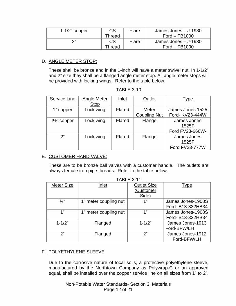
1-1/2” copper CS Thread
Flare James Jones – J-1930 Ford – FB1000
2” CS Thread
Flare James Jones – J-1930 Ford – FB1000
D. ANGLE METER STOP:
These shall be bronze and in the 1-inch will have a meter swivel nut. In 1-1/2” and 2” size they shall be a flanged angle meter stop. All angle meter stops will be provided with locking wings. Refer to the table below.
TABLE 3-10
Service Line Angle Meter Stop
Inlet Outlet Type
1” copper Lock wing Flared Meter Coupling Nut
James Jones 1525 Ford- KV23-444W
I½” copper Lock wing Flared Flange James Jones 1525F
Ford FV23-666W- 2” Lock wing Flared Flange James Jones
1525F Ford FV23-777W
E. CUSTOMER HAND VALVE:
These are to be bronze ball valves with a customer handle. The outlets are always female iron pipe threads. Refer to the table below.
TABLE 3-11
Meter Size Inlet Outlet Size (Customer
Side)
Type
¾” 1” meter coupling nut 1” James Jones-1908S Ford- B13-332HB34
1” 1” meter coupling nut 1” James Jones-1908SFord- B13-332HB34
1-1/2” Flanged 1-1/2” James Jones-1913 Ford-BFW/LH
2” Flanged 2” James Jones-1912 Ford-BFW/LH
F. POLYETHYLENE SLEEVE
Due to the corrosive nature of local soils, a protective polyethylene sleeve, manufactured by the Northtown Company as Polywrap-C or an approved equal, shall be installed over the copper service line on all sizes from 1” to 2”.
Non-Potable Water Standards- Section 3, Materials Page 12 of 21
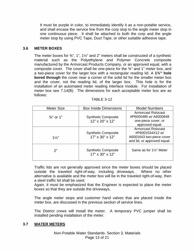
It must be purple in color, to immediately identify it as a non-potable service, and shall encase the service line from the corp stop to the angle meter stop in one continuous piece. It shall be attached to both the corp and the angle meter stop by using PVC Tape, Duct Tape, or other suitable adhesive tape.
3.6 METER BOXES
The meter boxes for ¾”, 1”, 1½” and 2” meters shall be constructed of a synthetic material such as the Polyethylene and Polymer Concrete composite manufactured by the Armorcast Products Company, or an approved equal, with a composite cover. The cover shall be one-piece for the ¾” and 1” meter box, and a two-piece cover for the larger box with a rectangular reading lid. A 1¾” hole bored through the cover near a corner of the solid lid for the smaller meter box and the cover, not the reading lid, of the larger box. This hole is for the installation of an automated meter reading interface module. For installation of meter box see 7.14(B). The dimensions for each acceptable meter box are as follows:
TABLE 3-12
Meter Size Box Inside Dimensions Model Numbers
¾” or 1”
Synthetic Composite
12” x 20” x 12”
Armorcast Rotocast #P6000485 w/ A6000848
one-piece cover, or approved equal.
1½”
Synthetic Composite
17” x 30” x 12”
Armorcast Rotocast #P6001534X12 w/
A6001643 two-piece cover and lid, or approved equal.
2”
Synthetic Composite
17” x 30” x 12”
Same as for 1½” Meter
Traffic lids are not generally approved since the meter boxes should be placed outside the traveled right-of-way, including driveways. Where no other alternative is available and the meter box will be in the traveled right-of-way, then a steel traffic lid shall be used. Again, it must be emphasized that the Engineer is expected to place the meter boxes so that they are outside the driveways. The angle meter stops and customer hand valves that are placed inside the meter box, are discussed in the previous section of service lines. The District crews will install the meter. A temporary PVC jumper shall be installed pending installation of the meter.
3.7 WATER METERS
Non-Potable Water Standards- Section 3, Materials Page 13 of 21

Water meter type and manufacturers shall be selected and installed by the District. Section 2.12 discusses general meter types.
3.8 MAIN LINE VALVES
A. BUTTERFLY VALVES:
1. General:
Butterfly valves shall be tightly closing, rubber seated valves conforming to AWWA C504. Valves must be Class 200-B designed for tight shut-off up to 200 psi. Valve disc shall rotate 90 degrees from fully open to tightly closed position.
2. Valve Body:
Shall be cast iron with integrally cast mechanical joints, ends for the pipe or flanged ends.
3. Valve Operators:
Shall be of a manual traveling nut type. Operators shall be equipped with a 2” AWWA square- operating nut. They shall be sealed, gasketed and lubricated for underground service. The operator shall be capable of withstanding an input torque of 450 ft. lbs at extreme operator position without damage.
4. Painting: See section 3.16 5. Marking:
The manufacturer shall show on the valve the valve size, manufacturer, class and year of manufacture.
6. Approved Valves:
Shall be either Pratt Groundhog or M & H 450
7. Available End Types:
TABLE 3-14
ENDS AVAILABLE BY VALVE SIZE
Type Pratt Groundhog M &H 450
Non-Potable Water Standards- Section 3, Materials Page 14 of 21
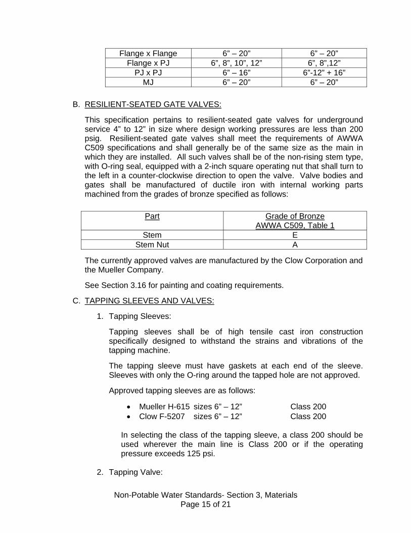
Flange x Flange 6” – 20” 6” – 20” Flange x PJ 6”, 8”, 10”, 12” 6”, 8”,12”
PJ x PJ 6” – 16” 6”-12” + 16” MJ 6” – 20” 6” – 20”
B. RESILIENT-SEATED GATE VALVES:
This specification pertains to resilient-seated gate valves for underground service 4” to 12” in size where design working pressures are less than 200 psig. Resilient-seated gate valves shall meet the requirements of AWWA C509 specifications and shall generally be of the same size as the main in which they are installed. All such valves shall be of the non-rising stem type, with O-ring seal, equipped with a 2-inch square operating nut that shall turn to the left in a counter-clockwise direction to open the valve. Valve bodies and gates shall be manufactured of ductile iron with internal working parts machined from the grades of bronze specified as follows:
Part Grade of Bronze AWWA C509, Table 1
Stem E Stem Nut A
The currently approved valves are manufactured by the Clow Corporation and the Mueller Company. See Section 3.16 for painting and coating requirements.
C. TAPPING SLEEVES AND VALVES:
1. Tapping Sleeves:
Tapping sleeves shall be of high tensile cast iron construction specifically designed to withstand the strains and vibrations of the tapping machine. The tapping sleeve must have gaskets at each end of the sleeve. Sleeves with only the O-ring around the tapped hole are not approved. Approved tapping sleeves are as follows:
• Mueller H-615 sizes 6” – 12” Class 200 • Clow F-5207 sizes 6” – 12” Class 200
In selecting the class of the tapping sleeve, a class 200 should be used wherever the main line is Class 200 or if the operating pressure exceeds 125 psi.
2. Tapping Valve:
Non-Potable Water Standards- Section 3, Materials Page 15 of 21

These shall meet all of the requirements under “gate valves” in the preceding section with the exception of items such as oversized seat rings to allow entry of the tapping machine cutter.
3. Painting and Coating:
See Section 3.16 for painting and coating requirements.
D. VALVE STACKS AND COVERS:
The valve stack shall be Schedule 40 PVC or DR 35 Sewer pipe 8” in diameter. See Plate W-26. The valve box cap shall be of the heavy duty, long body type. Approved cap is the Alhambra Foundry A-29608 (8”)
3.9 COMBINATION AIR RELEASE ASSEMBLIES
A. MECHANICAL ASSEMBLY:
As discussed in Section 2.8, the combination air release assembly has both the features of an air release valve and an air and vacuum valve. Both units shall be housed in a cast iron body and all internal parts such as the float, bushings, level pins, seat and baffle shall be either stainless steel or brass as furnished by the manufacturer. All assemblies shall be rated at 300-psi maximum operating pressure. Approved assemblies are as follows:
Size APCO Valve No.
Height Clow Model Design
Crispen Model Design
1” 143C 10” A U10 2” 145C 12” B U20 3” 147C 15” C U30 4” 149C 17” D U40
• Used only where the working pressure is under 125 psi for 1” and 165
psi for the larger sizes.
• The inlet threads shall be iron pipe threads of the same size as the valve.
B. HOUSING OR “CAN”:
Non-Potable Water Standards- Section 3, Materials Page 16 of 21

Shall be per Plates W-33, W-34, and W-35, or Armorcast, fiberglass reinforced polyester air/vac enclosure, P6002002 for ¾“ and 1”; P6002001 for 1½” and 2”. The choice of can must be approved by the District and depends entirely upon the location of the proposed installation.
C. SERVICE LINES:
Type K soft copper per Section 3.5. There shall be a corp. stop at the main per Section 3.5. See Section 3.5-F for poly sleeve requirement.
D. BALL VALVES:
James Jones 1900 or Ford B11-777 with a female iron pipe thread on each end and tee head.
E. GUARD POSTS:
See Section 3.17
3.10 BLOW-OFF ASSEMBLIES
A. TWO-INCH (2”) BLOW-OFF.
Reference Plates W-30 and W-31. Materials shall be as follows:
1. Service Line: Type K copper per Section 3.5 with a corp. stop and a saddle at the main per Section 3.5. Section 3.5-F for poly sleeve requirement.
2. 2” Ball Valve:
James Jones 1900 or Ford B11-777 with female iron pipe thread on each end and tee head.
3. Vault:
The same as for a meter installation up to 2”. See Section 3.5.
4. Plastic Plug:
This shall protect the top of ball valve.
B. Four Inch (4”) Blow –Off:
Non-Potable Water Standards- Section 3, Materials Page 17 of 21

Reference Plate W-32. Materials shall be as follows:
1. Service Line:
4” PVC or DIP per Section 3.8. There shall be a bottom outlet tee on the main per Section 3.4, which also discussed other miscellaneous fittings.
2. 4” Valve:
Butterfly valve per Section 3.8
3. Flanged Spool:
Made of Ductile Iron per Section 3.4
4. 4” Brass Nipple
5. 4” Angle Meter Valve:
Approved is Clow/Rich No. 125 all bronze wharf hydrants with 4” iron pipe thread inlet and one 4” outlet.
6. Vault:
Armorcast polymer box # A6001974PCX12, 24x36x12, with A6001975 Cover or Concrete box with cast iron cover. Approved are Brooks 72 PB which is 17” x 41” or Quikset W44 which is 16” x 44”. Both shall have cast iron covers.
7. Guard Posts: Required where an above ground blow-off is located in undeveloped areas.
3.11 PIPE TRENCH MATERIALS
Refer to Plate W-11 for trench cross-section terminology. A. WITHIN PIPE ZONE:
The pipe zone extends from the bottom of the trench to 12” above the top of the pipe. The material within this zone shall be a clean, well-graded, imported sand with sizes within the following ranges:
Sieve Sizes Percent Passing
Non-Potable Water Standards- Section 3, Materials Page 18 of 21

No.4 100 No.8 80-95
No.200 0-10
B. ABOVE PIPE ZONE:
The material shall conform to the requirements of the City or County or CalTrans, entity who has jurisdiction in the area. In the absence of stricter requirements, the material above the pipe zone shall be native material that does not contain rocks larger than 6” and shall be made so graded that at least 40 percent of the material passes the No.4 sieve.
C. SPECIAL SLURRY BACKFILL:
For pipelines that are laid in an already paved street the entity that has jurisdiction in the area may require the backfill above the pipe zone to be one sack slurry mix in lieu of compacted soil backfill. The slurry mix shall have no less than one sack cement per cubic yard.
3.12 ROADWAY MATERIALS
Pavement materials for resurfacing of trenches out in existing pavement shall comply with the requirements of the entity that has jurisdiction over the area. Asphalt, aggregate base and aggregate sub-base specifications are those set at by the latest published edition of California, Department of Transportation, Standard Specifications.
3.13 CONCRETE MATERIALS
Approved concrete material shall be based on the 28 day compressive strength and shall be chosen according to the following chart showing its intended use:
Class Application 28 Day Compressive
Strength, Minimum
PSI
Maximum Aggregate
Size, Inches
Slump Minimum Inches
Slump Maximum
Inches
A Walls, structures and reinforced encasements
3,500 1-1/2” 3 6
B Thrust blocks, non-reinforced pipe encasement, non-structural
3,00 1-1/2” 2 6
Non-Potable Water Standards- Section 3, Materials Page 19 of 21

use C Pump mix for
abandoning lines
1,000 3/8” Adequate for pumping
Adequate for pumping
3.14 REINFORCING STEEL
A. REBAR:
Shall be Grade 40 minimum deformed bars conforming to ASTM A615, accurately placed securely in position. Where bars are spliced, they shall be lapped at least twenty (20) times diameter or butt-welded, except where otherwise shown on the plans.
B. MESH REINFORCEMENT:
Mesh reinforcement shall conform to the requirements of ASTM A185, wire gauge and mesh dimensions will be as shown on the plans.
3.15 PAINTING
This section will only cover the paint materials. “Painting” as it relates to construction is discussed in Section 7.17.
All paint colors shall be as specified or as selected by the District. Paints shall be delivered to the job site in original, unopened cans or packages bearing the brand name and manufacturer’s name. In general, all above ground pipes and facilities will be painted or marked with Safety Purple alkyd enamel in a manner indicated by the District Inspector. Paints specified shall be used unless specific written approval is obtained in advance to use other products.
3.16 PLASTIC FILM WRAP:
This wrap shall be used around all buried valves, bolted flanges and other fittings. The polyethylene film shall be of virgin polyethylene as produced from Dupont Alathon resin and shall meet the requirements of ASTM Designation D 1248 for Type I, Class A, Grade E-1, and shall have a flow rate or nominal melt index of 0.4 g/min./maximum.
The polyethylene film shall be 6 mils in thickness. The length shall be sufficient to firmly attach the film to the pipe on either side of the valve, flange, or fitting. The following minimum flat sheet widths shall be used for the specified valve sizes:
Nominal Valve or Flange Size Minimum Flat Sheet Width
4” 24” 6” 24” 8” 24”
Non-Potable Water Standards- Section 3, Materials Page 20 of 21
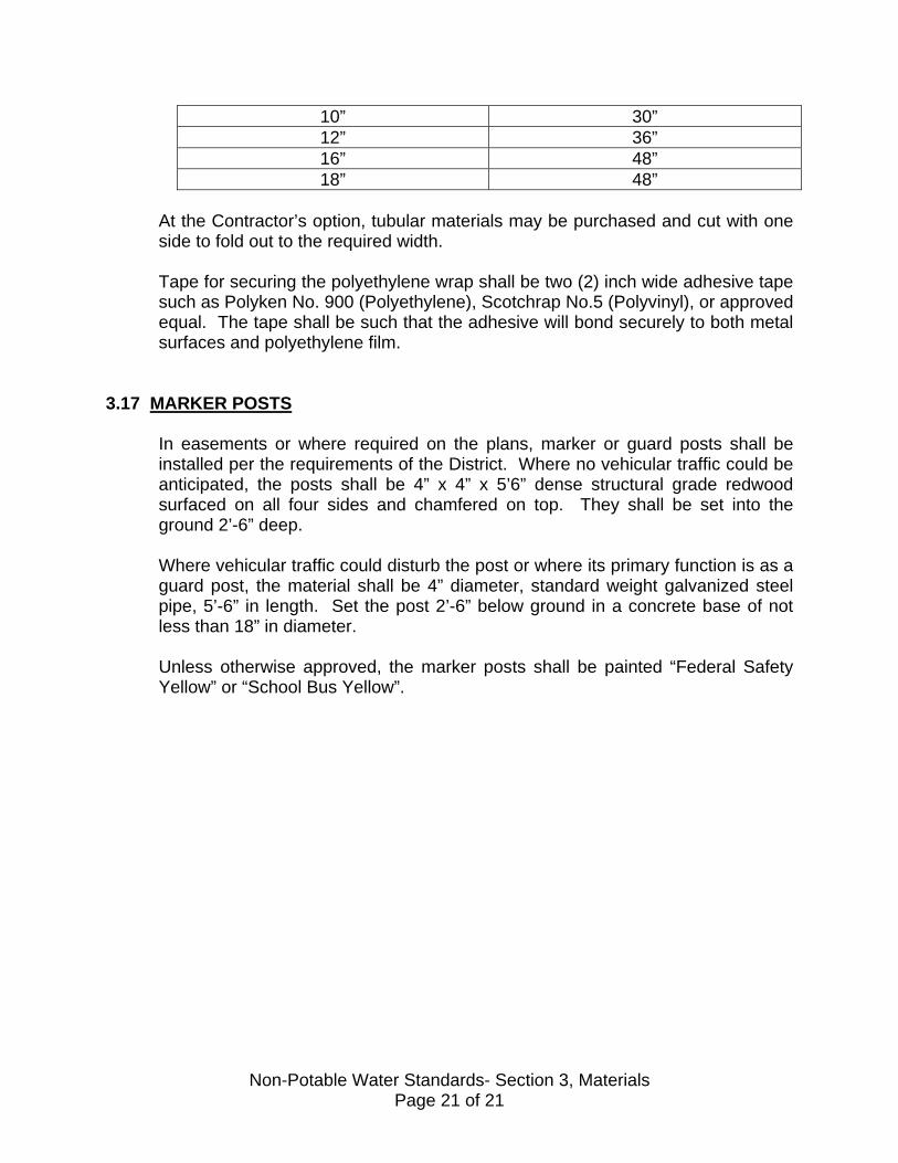
10” 30” 12” 36” 16” 48” 18” 48”
At the Contractor’s option, tubular materials may be purchased and cut with one side to fold out to the required width.
Tape for securing the polyethylene wrap shall be two (2) inch wide adhesive tape such as Polyken No. 900 (Polyethylene), Scotchrap No.5 (Polyvinyl), or approved equal. The tape shall be such that the adhesive will bond securely to both metal surfaces and polyethylene film.
3.17 MARKER POSTS
In easements or where required on the plans, marker or guard posts shall be installed per the requirements of the District. Where no vehicular traffic could be anticipated, the posts shall be 4” x 4” x 5’6” dense structural grade redwood surfaced on all four sides and chamfered on top. They shall be set into the ground 2’-6” deep. Where vehicular traffic could disturb the post or where its primary function is as a guard post, the material shall be 4” diameter, standard weight galvanized steel pipe, 5’-6” in length. Set the post 2’-6” below ground in a concrete base of not less than 18” in diameter. Unless otherwise approved, the marker posts shall be painted “Federal Safety Yellow” or “School Bus Yellow”.
Non-Potable Water Standards- Section 3, Materials Page 21 of 21
SECTION 4
PLAN PREPARATION 4.1 GENERAL
The District has established procedures that must be followed in the preparation of plans. Deviations from these requirements, unless specifically authorized will be cause for rejection by the District. All Engineers preparing plans should have in their possession a complete set of these Standards. All work shall be in ink on Mylar sheets. The Engineer has a distinct responsibility to follow the progress of the work and to submit change orders or to incorporate “As-Built” information on the drawings. It should be understood that the responsibility for accuracy and completeness of the drawing rests with the Developer’s Engineer. By signing the drawings, the District Manager attests to the fact that the plans have been reviewed and that the District has authorized construction provided that all fees and required documents have been submitted.
4.2 SHEET SIZE AND MARGINS
Overall dimensions is 24” x 36”. Margins shall be 1-1/2” on the left; all others are one-half inches.
4.3 SIGNATURE BLOCK
All sheets of the plan shall have an approved title block, see Plate No.2. The approval blocks shall be signed before any construction can occur. Any changes to the plans after initial approval shall be shown as revisions and shall be approved by the District.
4.4 COVER SHEET
This shall be the first sheet in the set and shall contain: A. INDEX MAP:
A map with an overall plan at a scale of 1” = 100’ showing the general layout of non-potable waterlines, sizes, valve locations, named streets, tract boundaries, lot boundaries and numbers, a sheet index and other pertinent information. Care must be exercised to make sure scale and orientation are correct since these index maps are used to produce a water atlas and incorrectly drawn maps will be have to be redrawn.
Non-Potable Water Standards- Section 4, Plan Prep. Page 1 of 8
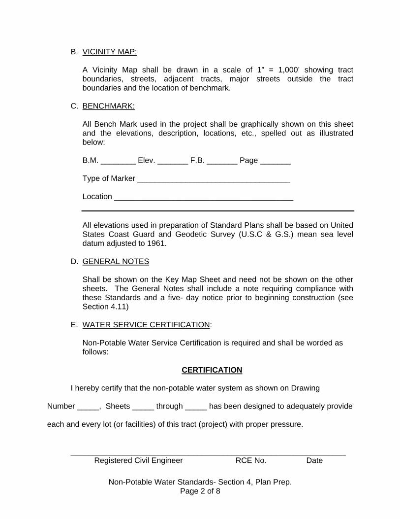
B. VICINITY MAP:
A Vicinity Map shall be drawn in a scale of 1” = 1,000’ showing tract boundaries, streets, adjacent tracts, major streets outside the tract boundaries and the location of benchmark.
C. BENCHMARK:
All Bench Mark used in the project shall be graphically shown on this sheet and the elevations, description, locations, etc., spelled out as illustrated below: B.M. ________ Elev. _______ F.B. _______ Page _______ Type of Marker ___________________________________ Location _________________________________________ All elevations used in preparation of Standard Plans shall be based on United States Coast Guard and Geodetic Survey (U.S.C & G.S.) mean sea level datum adjusted to 1961.
D. GENERAL NOTES
Shall be shown on the Key Map Sheet and need not be shown on the other sheets. The General Notes shall include a note requiring compliance with these Standards and a five- day notice prior to beginning construction (see Section 4.11)
E. WATER SERVICE CERTIFICATION:
Non-Potable Water Service Certification is required and shall be worded as follows:
CERTIFICATION I hereby certify that the non-potable water system as shown on Drawing Number _____, Sheets _____ through _____ has been designed to adequately provide each and every lot (or facilities) of this tract (project) with proper pressure. _______________________________________________________________ Registered Civil Engineer RCE No. Date
Non-Potable Water Standards- Section 4, Plan Prep. Page 2 of 8

If the project does not involve specific lots, then substitute the words “…
Designed to adequately provide for the development said system is intended to Serve”.
Further, the Engineer’s California Registration stamp including license expiration date shall be placed on the cover sheet.
F. “AS-BUILT” INFORMATION:
On the cover sheet there shall be a block to be used for “As-Built” information. It shall be as follows:
MATERIAL LIST
ITEM SUPPLIER AND/OR
MANUFACTURER
MODEL/TYPE NO.
NO.
Pipe Services/Sizes Valves Brass Products Prior to submittal of As-Built drawings, the pertinent information shall be completed by the Developer’s Engineer.
G. “AS-BUILT CERTIFICATION”:
“As-Built” certification is also required. The wording shall be as follows: “AS-BUILT” CERTIFICATE I hereby certify that the work shown on Drawing No. ______ Sheet _____ through _____ inclusive, marked “As-Built” has been constructed in conformance with the lines and grades as shown on said Plans and referred Specifications.
Registered Civil Engineer RCE No. Date
Non-Potable Water Standards- Section 4, Plan Prep. Page 3 of 8
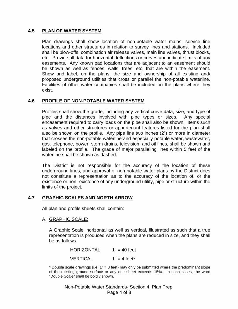
4.5 PLAN OF WATER SYSTEM
Plan drawings shall show location of non-potable water mains, service line locations and other structures in relation to survey lines and stations. Included shall be blow-offs, combination air release valves, main line valves, thrust blocks, etc. Provide all data for horizontal deflections or curves and indicate limits of any easements. Any known pad locations that are adjacent to an easement should be shown as well as fences, walls, trees, etc, that are within the easement. Show and label, on the plans, the size and ownership of all existing and/ proposed underground utilities that cross or parallel the non-potable waterline. Facilities of other water companies shall be included on the plans where they exist.
4.6 PROFILE OF NON-POTABLE WATER SYSTEM
Profiles shall show the grade, including any vertical curve data, size, and type of pipe and the distances involved with pipe types or sizes. Any special encasement required to carry loads on the pipe shall also be shown. Items such as valves and other structures or appurtenant features listed for the plan shall also be shown on the profile. Any pipe line two inches (2”) or more in diameter that crosses the non-potable waterline and especially potable water, wastewater, gas, telephone, power, storm drains, television, and oil lines, shall be shown and labeled on the profile. The grade of major paralleling lines within 5 feet of the waterline shall be shown as dashed. The District is not responsible for the accuracy of the location of these underground lines, and approval of non-potable water plans by the District does not constitute a representation as to the accuracy of the location of, or the existence or non- existence of any underground utility, pipe or structure within the limits of the project.
4.7 GRAPHIC SCALES AND NORTH ARROW
All plan and profile sheets shall contain: A. GRAPHIC SCALE:
A Graphic Scale, horizontal as well as vertical, illustrated as such that a true representation is produced when the plans are reduced in size, and they shall be as follows: HORIZONTAL 1” = 40 feet VERTICAL 1” = 4 feet* * Double scale drawings (i.e. 1” = 8 feet) may only be submitted where the predominant slope of the existing ground surface or any one sheet exceeds 15%. In such cases, the word “Double Scale” shall be boldly shown.
Non-Potable Water Standards- Section 4, Plan Prep. Page 4 of 8
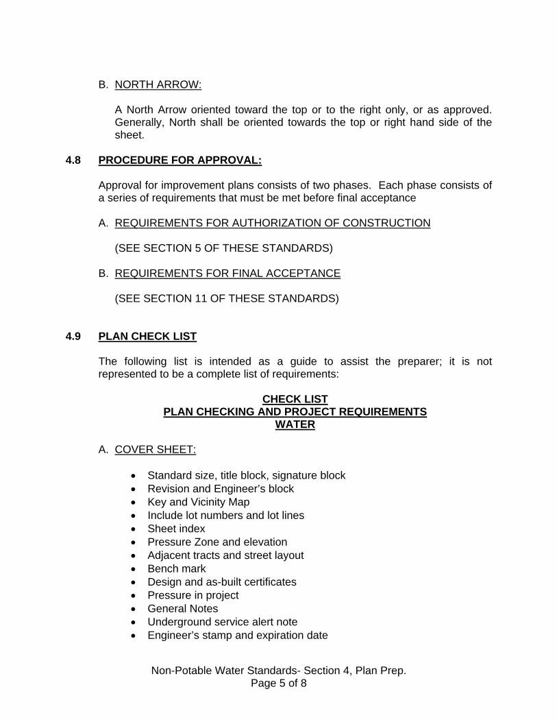
B. NORTH ARROW:
A North Arrow oriented toward the top or to the right only, or as approved. Generally, North shall be oriented towards the top or right hand side of the sheet.
4.8 PROCEDURE FOR APPROVAL:
Approval for improvement plans consists of two phases. Each phase consists of a series of requirements that must be met before final acceptance A. REQUIREMENTS FOR AUTHORIZATION OF CONSTRUCTION
(SEE SECTION 5 OF THESE STANDARDS)
B. REQUIREMENTS FOR FINAL ACCEPTANCE
(SEE SECTION 11 OF THESE STANDARDS)
4.9 PLAN CHECK LIST
The following list is intended as a guide to assist the preparer; it is not represented to be a complete list of requirements:
CHECK LIST PLAN CHECKING AND PROJECT REQUIREMENTS
WATER
A. COVER SHEET:
• Standard size, title block, signature block • Revision and Engineer’s block • Key and Vicinity Map • Include lot numbers and lot lines • Sheet index • Pressure Zone and elevation • Adjacent tracts and street layout • Bench mark • Design and as-built certificates • Pressure in project • General Notes • Underground service alert note • Engineer’s stamp and expiration date
Non-Potable Water Standards- Section 4, Plan Prep. Page 5 of 8
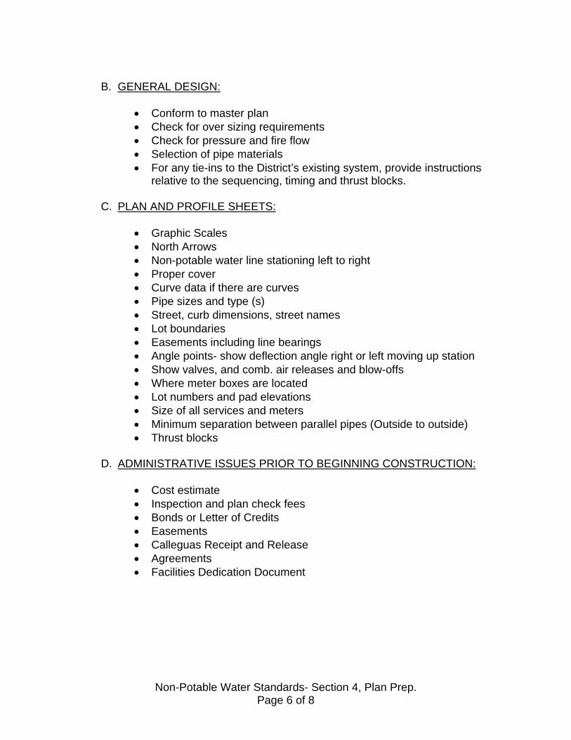
B. GENERAL DESIGN:
• Conform to master plan • Check for over sizing requirements • Check for pressure and fire flow • Selection of pipe materials • For any tie-ins to the District’s existing system, provide instructions
relative to the sequencing, timing and thrust blocks.
C. PLAN AND PROFILE SHEETS:
• Graphic Scales • North Arrows • Non-potable water line stationing left to right • Proper cover • Curve data if there are curves • Pipe sizes and type (s) • Street, curb dimensions, street names • Lot boundaries • Easements including line bearings • Angle points- show deflection angle right or left moving up station • Show valves, and comb. air releases and blow-offs • Where meter boxes are located • Lot numbers and pad elevations • Size of all services and meters • Minimum separation between parallel pipes (Outside to outside) • Thrust blocks
D. ADMINISTRATIVE ISSUES PRIOR TO BEGINNING CONSTRUCTION:
• Cost estimate • Inspection and plan check fees • Bonds or Letter of Credits • Easements • Calleguas Receipt and Release • Agreements • Facilities Dedication Document
Non-Potable Water Standards- Section 4, Plan Prep. Page 6 of 8
4.10 LANGUAGE FOR DEDICATION OF FACILITIES TO THE DISTRICT
The following language is intended as an example of standard language for the dedication of facilities to the District. It shall be modified as necessary to fit a particular set of circumstances. A. GRANT DEED, QUITCLAIM DEED, BILL OF SALE OR OTHER:
All of its rights, title, and interests in and to the non-potable water system, pipelines, and appurtenances thereto as located in, on, over, under and across streets, easements and rights-of-way shown on Tract ________ as per map thereof recorded in Book____, Page _____, and shown on the easement(s) as per Document No. _______, recorded on ____________________ of Official Records, in the Office of the County Recorder, County of Ventura, State of California.
B. EASEMENT DEED:
An easement and right-of-way to lay, construct, repair, maintain, operate, renew and replace non-potable pipeline and appurtenances incidental thereto for the transportation of non-potable water with the rights to ingress and egress to and from same, in, over, under and across the following described real property in the County of Ventura, State of California, and rights to disturb the surface of the easement area or surface improvements constructed by the servient tenant wherein the responsibility for replacement or restoration shall belong to the servient tenant unless otherwise specified herein. The District may add additional language as required.
4.11 NON-POTABLE WATER CONSTRUCTION NOTES: (also see Section #1)
The Standard Notes shown on the following page(s) should be included on the cover sheet as applicable. They are subject to change to suit the needs of the District:
1. Contractor shall notify the District at (805) 482-6562 five (5) days prior to commencing construction.
2. All construction shall conform to the District’s Non-Potable Water Design and Construction Standards adopted on ___________________ and as amended. 3. Pipe shall be PVC Class 200 AWWA C900 unless otherwise specified. (see Note #1, Section #1, Paragraph 1.7)
Non-Potable Water Standards- Section 4, Plan Prep. Page 7 of 8

4. Connections to the existing non-potable waterline shall be done only in the presence of the District’s Inspector or authorized District’s Representative. 5. Only District Personnel shall operate any valves on the existing non-potable water system unless authorized and in the presence of a District Representative.
6. Separation between non-potable water, potable water and wastewater lines shall be in accordance with Plate No.____.
7. No Fire Hydrants shall be connected to the Non-Potable water system per the Ventura County Fire Department requirements. 8. Utility locations and depths shown hereon have been plotted in accordance with the data furnished by the respective Utility Companies. The Engineer assumes no responsibility for the accuracy of the information received from each company. It is the Contractor’s responsibility to protect all public and private property in so far as it may be endangered by the Contractor’s operation. The Contractor in his bid shall absorb all costs for protecting, removing, and restoring existing improvements.
9. All trench backfill and compaction in public right-of-way above the pipe zone will be under the supervision of the City or County Inspector.
10. Detectable ribbon, purple in color, at least 4” in width and marked with “Reclaimed Water Pipeline Buried Below”, or similar text, to be placed 18” to 24” over pipeline prior to final backfilling for location and identification purposes. 11. Based upon static conditions, the maximum and minimum pressures for the _________ ft. zone are calculated to be _________ psi (lots #_____) and _______ psi (lot # _____), respectively.
12. Non-potable water lines shall be hydrostically tested after installation, backfilling and compaction.
13. All construction shall conform to the approved plans unless change order request is submitted and approved by the District.
14. The District does not warrant or guarantee the accuracy of locations and grades of main line, service lines and laterals as shown on these plans.
15. Under Service Alert: Call USA-SC for underground locating two (2) working days prior to any excavation (1-800-422-4133).
16. Prior to construction, Owner/Developer shall provide to the Inspector a current copy of approved insurance certificate.
17. All valve covers shall be painted purple.
Non-Potable Water Standards- Section 4, Plan Prep. Page 8 of 8

SECTION 5
FEES, CHARGES AND REQUIREMENTS FOR AUTHORIZATION OF CONSTRUCTION
5.1 GENERAL:
The authority for fees/charges is generally established in the District Code. The Board Resolution(s) adopts specific fees/charge amounts. The Board as required by law only adopts all fees/charges amounts following the conducting of public hearings. Copies of the current documents are available.
5.2 PLAN CHECK FEE
When non-potable water plans are first submitted, the Developer shall pay a plan check fee to the District. This fee shall be at the current rates using the Developer’s Engineer’s estimate of the cost of improvements. The District shall approve this estimate. The minimum plans check Board Resolution shall establish fee and minimum change order fee. Under no circumstances shall refunds of the plan check fee be made. However, the plan check fee required may be increased if actual or subsequent estimated costs exceed that used for initial fee calculation.
5.3 SUBMITTAL OF BLUELINE PRINTS (FOR PLAN CHECK)
Three sets of the blue line prints of the proposed non-potable water improvements, one copy of the final tract map (where appropriate), one complete set of street improvement plans, and three copies of the cost estimates shall be submitted together with the plan check fee for the first plan check. Plans illustrating an incomplete design and drafting detail may not meet minimum standards and may be just cause for rejection of the first plan check. The Developer or Developer’s Engineer shall submit preliminary plans completed in accordance with these Standards. The Developer and Engineer should be aware that most projects involve several plan checks/submittals before the drawings are deemed to be satisfactory.
5.4 SPECIAL PROVISIONS
If there are unusual conditions that would require substantial deviation from the District’s Standards, particularly with respect to service pressures, such deviations should be submitted in writing prior to tentative map and/or development project approval, or in any case prior to submittal of the first plan check.
Non-Potable Water Standards- Section 5, Fees Page 1 of 5

5.5 INSPECTION FEES
The District staff analyzes the plans and materials as submitted and prepares and sends comments to the Developer’s Engineer. Upon receipt of revised plans, the Developer’s Engineer prepares a final cost estimate for the proposed improvements. The inspection fee amounts using the most current cost rates (percentage figures) and unit prices applicable at the time the project goes to the Board for authorization to construct shall be determined and paid. In addition, the following is applicable: A. MINIMUM INSPECTION FEE:
A minimum inspection fee shall be per Board resolutions. B. SPECIAL SITUATION INSPECTION FEE:
Construction inspection fees for special situations, as determined by the District, such as inspections on Saturdays, Sundays, or District holidays or beyond the normal working hours, shall be charged as follows:
1. For inspection of special situations during the normal working hours,
the current inspector rate per hour worked, plus an allowance for fringe benefits (currently 40 percent), plus 30 percent for overhead.
2. For inspection during overtime periods, the current inspector rate per
hour worked multiplied by a factor of 1-1/2, plus 40% fringe benefits, plus 30 % for overhead.
3. For inspection during Sundays and Holidays, the current inspector rate
per hour worked, multiplied by a factor of 2, plus 40% fringe benefits, plus 30% for overhead.
5.6 EASEMENTS
Any easements necessary must have deeds submitted for checking at this time or must be shown on the tract map before recordation. Also see Section 2.5 and 4.0 of these Standards for easement requirements.
5.7 AGREEMENTS, BONDS, AND INSURANCE CERTIFICATES
Staff will provide the Developer with proper forms and the Developer shall submit the following: A. AGREEMENT
Non-Potable Water Standards- Section 5, Fees Page 2 of 5
The Developer shall submit an Agreement for Construction of Non-Potable Water Facilities (in triplicate with notarized signatures).
B. INSURANCE
Insurance policy with limits as stated in “ Agreement” Attention is particularly called to the District’s requirements concerning submittal of an “Accord” form. The insurance certificate shall include general liability, auto liability and workers compensation insurance in amounts as required by the District. The District, its officers, employees and agents, shall be named as additional insured. The notice of cancellation period must be no less than 30 days. Any reference in the cancellation period must be no less than 30 days. Any reference in the cancellation clause to “endeavor to” or “but failure to mail such notice shall impose no obligation or liability of any kind upon the company” must be deleted. Also, the words “ This certificate is issued as a matter of information only and confers no rights on the certificate holder “ must be deleted. If disclaimer cannot be deleted from the Accord form, then a signed warranty letter must be attached to the certificate.
C. FAITHFUL PERFORMANCE BOND
The District reserves the right to request the District Accord form utilized. The Developer shall submit a Faithful Performance Bond (in triplicate and signatures notarized) equivalent to 100% of the estimated cost including contingencies of construction. Note: Certificates of Deposits and Letters of Credit may be substituted.
D. LABOR AND MATERIALS BOND
The Developer shall submit a Labor and Materials Bond (in triplicate and signatures notarized) equivalent to 100 % of the estimated cost. Note: Certificate of Deposit or Letter of Credit may be substituted.
E. CALLEGUAS RECEIPT AND RELEASE ` The Developer shall have made arrangements with the Calleguas Municipal
Water District to satisfy the requirements of their Ordinance No. 14, that assesses fees for capital projects. The District requires a copy of the CMWD “release and receipt” for the project.
5.8 WILL-SERVE LETTER
Non-Potable Water Standards- Section 5, Fees Page 3 of 5

Prior to or concurrent with any District authorization to construct facilities or prior to any parcel receiving non-potable water service (one or both may be applicable), the District shall issue a Will- Serve Letter indicating that the subject property lies within the District’s service area and that the District will provide water service subject to certain terms, conditions and limitations as outlined in the Will- Serve Letter, as required by the these Standards. For tracts, issuance of a Will- Serve Letter by the District shall normally precede recordation and construction.
5.9 APPROVAL FOR CONSTRUCTION
Upon receipt of all documents, bonds, fees and checking for all the documents, bonds and fees, the staff shall prepare a resolution for the District’s action, which is accompanied by or refers to the following material:
• Original water plans. • Agreement for construction of water facilities. • Faithful Performance Bond. • Labor and Materials Bond.
The District will sign the original plans only after the approval by the Board, and will notify the Developer’s Engineer that the plans are signed and available. The Developer’s Engineer will then provide the District with two sets of blue line prints, and the original drawings will be returned to the Developer’s Engineer until they are “As-Built”, at which time the originals become the District’s property. No construction should occur before the plans are signed and before the proper five days District notification has been given. This notification will allow time for a pre-construction meeting of all interested parties. The District and the Developer have a direct relationship via the documents outlined above. Therefore, to the extent possible, correspondence and verbal communication should be between these parties rather than District/ Contractor or Subcontractor communications excluding the Developer.
5.10 SPECIAL FACILITIES SURCHARGE & FIRE FLOW SURCHARGE
Selected water service zones may be subject to the special facilities surcharge fees that are due and payable along with the plant investment fee.
5.11 SERVICE LINE OR METER INSTALLATION
In general, the Developer will install the required service lines as part of the development project. The District will then install the meter.
5.12 SPECIAL CHARGES
Non-Potable Water Standards- Section 5, Fees Page 4 of 5

If there are items requiring special approval, the District may require deposition of funds or agreements for funds in the future to provide for operation and maintenance of substandard system.
5.13 MAIN LINE EXTENSION AND OVERSIZING AGREEMENTS
In general, if any Developer desires to enter into a reimbursement agreement with the District, such arrangement shall be made prior to the time authorization to construct the waterlines (or system) is given to the District. The reimbursement agreements for main line extensions involve future payments to the Developer installing the improvements if and when the District receives funds from other benefiting properties. In the case of the District contribution for over-sizing a line, no District contribution can be considered unless the line is 10” or greater in diameter.
Non-Potable Water Standards- Section 5, Fees Page 5 of 5
SECTION 6
CONSTRUCTION STAKING 6.1 GENERAL REQUIREMENTS
Construction staking is the responsibility of the Developer; it’s Engineer or Contractor. When the term is used, it should be remembered that it encompasses construction pipeline markings that may not involve any staking, such as marking on pavement. Stakes or marks will be set parallel to the pipeline alignment at an offset distance and direction agreed upon with the contractor, but in no case shall construction stakes be offset more than 10 feet. Stakes or marks will be set at no greater interval than 50 feet on straight alignments. For horizontally and vertically curved pipelines, the stake or mark interval shall be 10 feet.
6.2 PRESERVATION OF STAKES Construction stakes or construction markings shall be carefully preserved by the Contractor until after the completed worked is accepted by the District. If two or more consecutive stakes are knocked out during construction, new stakes shall be set at the Contractor’s expense.
6.3 SERVICE LINES
For each service line, a stake shall be placed near the property line, referenced to show its location. If the meter box installation is not anticipated prior to field acceptance, then the stake shall be a minimum 2” x 4” redwood post 2 feet in length with 18” buried.
6.4 “AS-BUILT”
The stationing for each service line is required on the “As-Built” drawings.
Non-Potable Water Standards- Section 6, Const. Staking Page 1 of 1
SECTION 7
CONSTRUCTION 7.1 GENERAL REQUIREMENTS
This Section describes the use of materials and workmanship to be employed in construction of the non-potable water system. The Developer/Engineer shall prepare such general and special specifications as are necessary to define the nature and location of the work, contractual arrangements, payment for work and any other matters concerning the owner or his Contractor; these items are not discussed within the Standards presented here. A. USE OF THIS SECTION:
The Construction Section is intended to highlight the features of construction that are deemed to be most significant. In any construction activity, the recommendations of the manufacturer of a product, especially where more stringent, should apply. Also, the omission of a particular practice, that is not considered to be a good construction technique common to the construction industry, should not be construed to mean that it is not required. There are a number of construction activities that pertains to all pipe types and these will be presented first. Specialized activities unique to a particular pipe type will be covered separately. Specific references that are incorporated into this Section include:
• AWWA C206 “Field Welding of Steel Pipes” • AWWA Manual M11 “Steel Pipe-Design and Installation” • AWWA Manual M23 “PVC Pipe- Design and Installation”
• C600-99 Installation of Ductile Iron Water Mains
Finally, Section 3 of these Standards contains material descriptions and the Developer/ Contractor should use that Section along with this Section and their respective plates as a reference. Section 9 describes testing procedures and requirements.
Non-Potable Water Standards- Section 7, Construction Page 1 of 21
B. PROTECTION/ OPERATION OF EXISTING POTABLE WATER SYSTEM.
A primary concern of the District is the protection and operation of the existing potable water system. No Developer or Contractor will be allowed to operate any existing water valves or to cause a shutdown of any portion of the District’s potable water system without prior approval from a District’s representative. In general, the District personnel will do any operation of valves in a planned shutdown. Any planned shutdown should be discussed at the pre-construction meeting or at least 3 working days in advance. Shutdowns will only be allowed if no other reasonable alternative exists, such as the use of hot-tap connection in lieu of cut-in. When shutdowns are required in a part of the District’s system, the District will expect evaluation of whether the shutdown should be done during the day or during the night. Contractor/ Developer economics shall weigh less heavily in the decision than in the interruption and inconvenience to existing customers. Any shutdown shall involve a thorough notification plan for existing customers as well as the provision of bottled water, water tanks, etc, where appropriate.
C. QUALITY OF MATERIALS
Materials and equipment to be incorporated into the work shall be new and unused unless otherwise approved. In a case a reference is not clear as to which of several available grades is desired, the highest quality material shall be used. When construction bids are received directly from the District, such bids shall show the proposed pipe material and the manufacturer’s name, if more than one type is allowed. Contractor shall have at the job site or be able to supply upon request, certified copies of factory or laboratory test reports showing the strength and characteristics of the material used in the work. For all reinforced concrete work he shall furnish in advance of pouring concrete, and if requested, the mix design and calculated concrete strength as prepared by the concrete supplier.
D. SUBSTITUTION
Where articles or materials are specified by brand or trade name, alternative materials or articles equal to those specified may be approved provided the request for approval is in writing accompanied by supporting data, in ample time to permit investigation without delaying the work. Unless substitutions have been received prior approval, no deviation from the Standards will be allowed.
Non-Potable Water Standards- Section 7, Construction Page 2 of 21

E. QUALITY OF WORKMANSHIP:
Persons experienced in the specific work, under competent supervision and a first class manner to the District’s satisfaction will do all work. When work is being done directly for the District, the Contractor in the proposal shall name each sub-contractor and no substitution will be permitted without prior approval.
F. DEFECTIVE WORK:
Any defective materials or workmanship, that shall become evident within one year after field acceptance of completed work shall be replaced or repaired without cost to the District. Refusal of the Contractor to correct defective work that is clearly his responsibility will be considered just cause for exclusion from performing future work to be connected to the District’s water system. Such exclusion does not impair the District’s right to bring legal action to correct the deficiencies as well as to withhold exoneration of performance and payment bonds.
G. DISTRICT INSPECTION, FIELD ACCEPTANCE AND GUARANTEE PERIOD:
The District is responsible for inspection of all excavation; pipe laying including appurtenant structures, trench backfill within the pipe zone and testing. All such work shall be available for inspection at all times. It will be the Contractor’s responsibility to provide a five (5) working day notice to the District prior to the start of any work. Such notification will allow for scheduling a pre-construction meeting between interested parties. Failure to provide proper notification may delay the starting date since the District may not be able to inspect the work and cannot accept any work for which the inspection has not been arranged. It must be emphasized that the primary responsibility for compliance with all the District’s requirements and standards rests with the Developer and/or the Contractor of this basic responsibility. Field acceptance is made by the Inspector and will not coincide with the date of District’s acceptance of the work. However, the one-year guarantee period for all work shall begin as of District’s Board acceptance. As mentioned in Section 7.1E, any defective work discovered during this period shall be repaired or replaced and a new one-year period will begin for the corrected work. All holiday or weekend inspection will be subject to additional charges as discussed in Section 5.4.
Non-Potable Water Standards- Section 7, Construction Page 3 of 21

H. PUBLIC RELATIONS:
The Contractor shall conduct its affairs in a manner that will lessen the disturbance to residents in the vicinity of the work. In this regard, standard working hours as specified in the City or County encroachment permits shall be observed unless prior approval is received. The job site shall be maintained in a condition, that will not bring discredit to the District or its personnel, and all affected private improvements shall be restored to at least their original condition.
7.2 PERMITS
The following may be required of the Contractor: A. ENCROACHMENT:
Where construction will encroach into the public-right-of way, the Contractor shall obtain all necessary encroachment permits. Within the City of Camarillo, Thousand Oaks, Moorpark and Simi Valley, the permit is secured from the Public Works Department. Within the unincorporated area, the County requires a similar permit. Particular attention is called to Section 7.15 and the appropriate Plates.
B. EXPLOSIVES:
Where the Contractor anticipates the use of explosives in conjunction with the water construction, a blasting permit shall be first obtained from the Ventura County Sheriff’s Department, and all nearby property owners shall be notified. These permits are discretionary and may not be given for a particular circumstance.
7.3 SHIPMENT AND DELIVERY
All pipes shall be braced and stulled to prevent damage during shipment. Any damaged pipe or fittings delivered and unloaded at trench side shall be removed by the Contractor from the work site. With steel ML&C (mortar lined and coated), the off loading of the pipe as well as placement in the trench shall be done with straps at each end. Chains shall not be allowed to come into contact with the pipe.
Non-Potable Water Standards- Section 7, Construction Page 4 of 21
7.4 CLEARING AND GRUBBING
A. GENERAL:
Clearing and grubbing that consists of removal of objectionable material from the right-of-way, shall be done with caution such that existing waster water improvements, adjacent property and trees and shrubbery that are not to be removed shall be protected from injury or damage. Within non-potable water easements or right-of–way, trees, shrubs, fences and all other improvements that have to be removed to permit construction and that are intended for replacement, shall be replaced in kind or size (excluding native trees under 2-inch diameter or native brush) or with approved substitutes unless permission to exclude such replacement is obtained from the owner/agency or granted by the District.
B. REMOVAL AND DISPOSAL OF MATERIAL:
The Contractor shall be responsible for leaving the site in a neat and finished appearance, free from debris or inflammable material.
7.5 UTILITIES, EXISTING FACILITIES AND CONCRETE REMOVAL
A. ABANDONMENT:
Refer to Section 8 regarding abandonment of existing non-potable, potable water lines an/or structures.
B. UTILITIES AND EXISTING FACILITIES:
The existing utilities and/or facilities shown on the drawings or the location of which is made known to the Contractor prior to excavation shall be protected from damage during the excavation and backfilling of trenches and, if damaged, shall be repaired by and at the contractor’s expense. Any existing utility or facility not shown on the drawings or the location of which is not shown to the Contractor in sufficient time to avoid damage, if inadvertently damaged during excavation, shall be repaired by the Contractor; and adjustment in payment, if any, is subject to negotiation between the Contractor and the Developer without any District liability, unless it is a District sponsored project. Whether expressly indicated on the drawings or not, all Contractors shall call the Underground Service Alert prior to any construction of pipelines. Failure to do so shall not relieve the Contractor of any liability associated with disturbance/breakage of existing utilities.
Non-Potable Water Standards- Section 7, Construction Page 5 of 21
In case it shall be necessary to remove any such utilities, facilities or any portion thereof, the Contractor shall notify the District and the owner of the structure. The Contractor shall not interfere with said utility and./or facility structures until disposition of the obstruction to the work has been determined and/or notice to relocate or remove has been given by the District or authorized agent of the Owner of the utility and/or facility so affected. The fact that any underground utility and/or facility is not shown on the plans shall not relieve the Contractor of his responsibility to comply with these standards. It shall be the Contractor’s responsibility to ascertain prior to commencing work the existence of any underground utilities or facilities that may be subject to damage by reason of these operations. The District will provide service line location services of existing facilities upon request and with satisfactory notification in advance.
C. CONCRETE OR, MASONRY CONSTRUCTION REMOVAL:
At locations shown on the plans, portions of existing concrete pavements, curbs, gutters, sidewalks, foundations and other concrete or mortared structures shall be removed to the lines and elevations specified. Concrete structure or objects not shown or noted on the plans shall be removed where necessary and disposed of by the Contractor. Concrete removal operations in connection with the reconstruction of existing structures shall be performed without damage to any portions of the structure that is to remain in place. If damage occurs, the contractor shall repair any such damage at his own expense, to the satisfaction of the District. Repair/replacement of any sidewalks, curb and/or gutters shall be to the satisfaction of the City or County Public Works Department, as appropriate. Where existing reinforcement is to be incorporated in new work, such reinforcement shall be protected from damage and shall be thoroughly cleaned of all adhering material before being embedded in a new concrete.
7.6 EXCAVATION AND TRENCHING
A. GENERAL:
Trench excavation shall consist of all excavation involved in the grading and construction of the non-potable water line as shown on plans. The Contractor shall perform all excavation of every description and of whatever substances encountered, to depths indicated on the drawings or otherwise specified or required. During excavation, material suitable for backfilling shall be piled in an ordinary manner a sufficient distance from
Non-Potable Water Standards- Section 7, Construction Page 6 of 21
the banks of the trench to avoid overloading and to prevent slides or cave-ins. The material piles shall also not obstruct existing sidewalks or driveways unless it cannot be avoided. All excavated materials not required or unsuitable for backfill shall be removed. Such grading shall be done as may be necessary to prevent surface water from flowing into trenches or other excavations, and any water from any source accumulating therein shall be removed by pumping or by other approved methods. Such sheeting and shoring shall be done as may be necessary for the protection of the work and for the safety of personnel. Unless otherwise indicated, excavation shall be by open cut except that short sections of a trench may be tunneled if, in the opinion of the District, the pipe or duct can be safely and properly installed and backfill can be properly tamped in such a tunnel sections. If blasting is necessary, the Contractor shall notify the City or County of his blasting schedule and procedures and obtain a blasting permit, and shall observe all reasonable precautions in protecting life and property.
B. EXCAVATION:
Excavation for non-potable water lines shall be made only after pipe and other necessary materials are delivered on the work site. After such delivery, trench excavation shall proceed as rapidly as possible, and the pipe installed and the trench backfilled without undue delay. Where rock excavation is required, the rock shall be excavated to a minimum over depth of 6” below the trench depths indicated on the drawings or specified. Over depths in the rock excavation and unauthorized over depths shall be backfilled with the same material as the bedding zone. Whenever wet or otherwise unstable soil incapable of properly supporting the pipe as determined by the District is encountered in the bottom the trench, such soil shall be removed to the depth required and the trench backfilled to the proper grade with an appropriate material between a course sand and a crushed rock to provide a stable foundation.
C. SHORING:
All shoring for open excavations shall conforms to the State of California, Department of Industrial Relations, and Division of Industrial Safety “Construction Safety Orders” The Contractor shall be responsible for adequately shored and braced excavation so that the earth will not slide, move or settle, and so that all existing improvements of any kind will be fully protected from damage.
Non-Potable Water Standards- Section 7, Construction Page 7 of 21
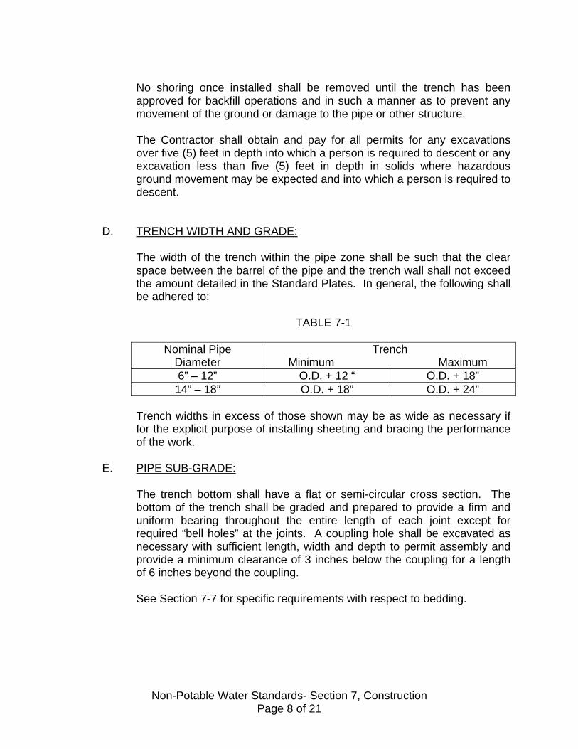
No shoring once installed shall be removed until the trench has been approved for backfill operations and in such a manner as to prevent any movement of the ground or damage to the pipe or other structure. The Contractor shall obtain and pay for all permits for any excavations over five (5) feet in depth into which a person is required to descent or any excavation less than five (5) feet in depth in solids where hazardous ground movement may be expected and into which a person is required to descent.
D. TRENCH WIDTH AND GRADE:
The width of the trench within the pipe zone shall be such that the clear space between the barrel of the pipe and the trench wall shall not exceed the amount detailed in the Standard Plates. In general, the following shall be adhered to:
TABLE 7-1
Nominal Pipe Diameter
Trench Minimum Maximum
6” – 12” O.D. + 12 “ O.D. + 18” 14” – 18” O.D. + 18” O.D. + 24”
Trench widths in excess of those shown may be as wide as necessary if for the explicit purpose of installing sheeting and bracing the performance of the work.
E. PIPE SUB-GRADE:
The trench bottom shall have a flat or semi-circular cross section. The bottom of the trench shall be graded and prepared to provide a firm and uniform bearing throughout the entire length of each joint except for required “bell holes” at the joints. A coupling hole shall be excavated as necessary with sufficient length, width and depth to permit assembly and provide a minimum clearance of 3 inches below the coupling for a length of 6 inches beyond the coupling. See Section 7-7 for specific requirements with respect to bedding.
Non-Potable Water Standards- Section 7, Construction Page 8 of 21

7.7 PIPE BEDDING AND LAYING
A. GENERAL:
This portion of the work includes the furnishing of all materials and their proper assembly to result in a first class waterline installation true to line and grade and free from leaks, cracks and obstruction. Where choices are allowed, the Contractor shall select such materials and construction methods that will result in a completed project in full conformance with these Standards. In that regard, refer to Section 3 (Materials) and the Plates for additional details. The Contractor is warned that the approved non-potable water pipeline design is based upon a proper combination of pipe strength and pipe support. No acceptance will be given unless the work of trenching, bedding, laying, backfilling and compacting is conscientiously done in accordance with the procedures outlined in these Standards. Except as otherwise approved or included in permits, the maximum length of open trench at any one time shall be 500 feet, or the distance necessary to accommodate the amount of pipe installed in a single day, whichever is greater. Experienced workmen, using not less than three consecutive grade points in common, shall transfer grades from ground surface to the bottom of the trench so that variations from a straight grade may be readily detected. Each length of pipe shall be laid on firm, approved bedding material as specified and shall have full bearing for its entire length between bell holes excavated in said bedding material to allow for undistracted assembly of all joints. Adjustments of pipe to line and grade shall be made by scraping away or filling in and tamping approved material under the body of pipe. No wedging or blocking with wood or soil to support the pipe will be permitted. Under no circumstances will a contractor be allowed to dump backfill materials on top of a pipe that is not continuously supported in its final grade position. Each pipe shall be laid true to line and grade and in such manner as to form a close concentric joint with the adjoining pipe, following manufacturer’s instructions for the specific jointing method being used. Pipe shall not be laid when the Engineer or Inspector determines that the condition of the trench or weather is unstable. As the work progresses, the interior of the water line shall be cleared of all dirt and superfluous materials of every description. If the maximum width of the trench at the top of the pipe is exceeded, the Contractor shall install such concrete cradling, pipe encasement or other bedding as may be required to support
Non-Potable Water Standards- Section 7, Construction Page 9 of 21

the added load of the backfill. Trenches shall be kept free from water until sufficient backfill has been applied to keep the pipe in place. At times when work is not in progress, open ends of pipe and fittings shall be securely closed to the satisfaction of the Inspector so that no trench water, earth or other substance will enter the pipe or fittings. Pipe or fittings damage during assembly shall be removed and replaced.
B. PIPE LAID ON BEDDING VS. EARTH MOUNDS:
The key elements to the pipe bedding are that the pipe ultimately be continuous supported and that the full 4 inches of bedding material (imported sand or better) be placed under the pipe. Where pipe is to be laid where considerable amounts of rock or cobblestone or groundwater are present, then the continuous bedding method shall be used. Earth mounds may be used, if specifically approved by the District Inspector, in areas exhibiting ideal pipe laying conditions where there is clear demonstration that the 4” bedding material will be placed after the pipe is laid in the trench. For the continuous bedding method, the trench bottom shall be over-excavated a minimum of 4” and brought back to grade with imported bedding material. Prior to lowering the pipe into the trench, coupling holes shall be excavated in the bedding with sufficient length, width and depth to permit assembly and provide a minimum of 2” below the coupling. For the earth mound method, the mounds shall be compacted firmly and of a size adequate to suspend the pipe 4” above the trench bottom while maintaining the pipe true to grade. Each length of pipe shall be laid on two mounds with the center of each placed at approximately one-fifth the distance from each end. Coupling holes shall provide a minimum clearance of 2”. After assembly, the trench zone shall be properly backfilled with imported bedding material. The bedding material shall then be compacted utilizing appropriate methods to provide a firm and uniform bedding throughout the entire length of pipe.
C. PIPE LAYING FOR PVC PIPE:
Pipe laying of PVC C900 pipe is very similar to that for other pipe types with the following exceptions:
1. Because it is a plastic product, the pipe should be covered with an
opaque material if it is be stored outside for a prolonged period of time (45 days).
2. In obtaining a square end cut, a PVC pipe cutter is recommended,
but conventional fine-tooth hand or power saws may be used.
Non-Potable Water Standards- Section 7, Construction Page 10 of 21

3. Field beveling of pipe ends after cutting can be done with special beveling tools or with such items as rasps.
4. In making the pipe conform to a curve, the pipe lengths should first
be assembled in a straight line and then bent as they are lowered into the trench.
5. Because PVC is non-conductive and subject to more damage if
struck with excavating equipment, a detectable ribbon at least 3” in width, 5 mil, purple in color, with the legend “Reclaimed Waterline Buried Below”, or similar, shall be installed a minimum of 12” but no greater than 24” above the pipeline. No detector wire is required when complying with this standard. See Section 3.3, B-5 for details.
D. PIPE LAYING FOR DUCTILE IRON PIPE:
Where approved for use, ductile iron pipe shall be laid in accordance with manufacturer’s instructions and in general compliance with the applicable procedures as listed for PVC pipe. Where specified the District may request a specification for such installation practices. Specific attention shall be given to the placement of the polyethylene encasement wrap and any tapping of the pipeline for services and/or other main connections.
7.8 THRUST BLOCKS, SUPPORTING OF VALVES, ETC.
A. SUPPORTING OF VALVES:
Valves and fittings shall be supported by the trench bottom and shall be independent of the pipe. When pouring thrust blocks around a fitting, the concrete should be around the fitting and not the joint.
B. THRUST BLOCKS:
These shall be placed as shown on the plans or as required by Plates W-23 and W-24. The concrete shall meet the requirements of Section 3.14. Care shall be taken to insure that the concrete is poured against undisturbed ground and the fitting to be anchored.
7.9 HOT TAPPING
Hot tapping shall only be done in the presence of the District Inspector or Representative. Section 3.8 discusses the tapping sleeve and valve requirements. The tapping mechanism shall be of the self purging type so that cutting chips are removed from the tapping machine and do not enter the pipeline.
Non-Potable Water Standards- Section 7, Construction Page 11 of 21
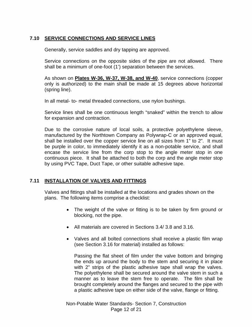
7.10 SERVICE CONNECTIONS AND SERVICE LINES
Generally, service saddles and dry tapping are approved. Service connections on the opposite sides of the pipe are not allowed. There shall be a minimum of one-foot (1’) separation between the services. As shown on Plates W-36, W-37, W-38, and W-40, service connections (copper only is authorized) to the main shall be made at 15 degrees above horizontal (spring line). In all metal- to- metal threaded connections, use nylon bushings. Service lines shall be one continuous length “snaked” within the trench to allow for expansion and contraction.
Due to the corrosive nature of local soils, a protective polyethylene sleeve, manufactured by the Northtown Company as Polywrap-C or an approved equal, shall be installed over the copper service line on all sizes from 1” to 2”. It must be purple in color, to immediately identify it as a non-potable service, and shall encase the service line from the corp stop to the angle meter stop in one continuous piece. It shall be attached to both the corp and the angle meter stop by using PVC Tape, Duct Tape, or other suitable adhesive tape.
7.11 INSTALLATION OF VALVES AND FITTINGS
Valves and fittings shall be installed at the locations and grades shown on the plans. The following items comprise a checklist:
• The weight of the valve or fitting is to be taken by firm ground or blocking, not the pipe.
• All materials are covered in Sections 3.4/ 3.8 and 3.16. • Valves and all bolted connections shall receive a plastic film wrap
(see Section 3.16 for material) installed as follows: Passing the flat sheet of film under the valve bottom and bringing the ends up around the body to the stem and securing it in place with 2” strips of the plastic adhesive tape shall wrap the valves. The polyethylene shall be secured around the valve stem in such a manner as to leave the stem free to operate. The film shall be brought completely around the flanges and secured to the pipe with a plastic adhesive tape on either side of the valve, flange or fitting.
Non-Potable Water Standards- Section 7, Construction Page 12 of 21
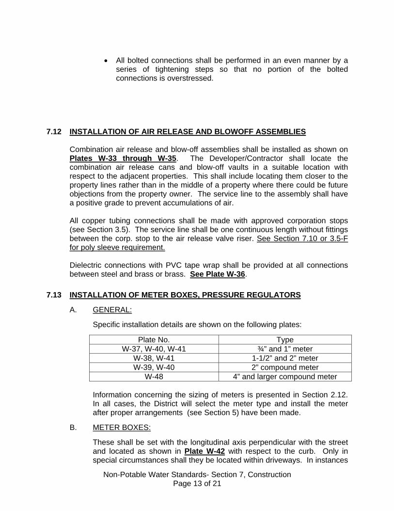
• All bolted connections shall be performed in an even manner by a
series of tightening steps so that no portion of the bolted connections is overstressed.
7.12 INSTALLATION OF AIR RELEASE AND BLOWOFF ASSEMBLIES
Combination air release and blow-off assemblies shall be installed as shown on Plates W-33 through W-35. The Developer/Contractor shall locate the combination air release cans and blow-off vaults in a suitable location with respect to the adjacent properties. This shall include locating them closer to the property lines rather than in the middle of a property where there could be future objections from the property owner. The service line to the assembly shall have a positive grade to prevent accumulations of air. All copper tubing connections shall be made with approved corporation stops (see Section 3.5). The service line shall be one continuous length without fittings between the corp. stop to the air release valve riser. See Section 7.10 or 3.5-F for poly sleeve requirement. Dielectric connections with PVC tape wrap shall be provided at all connections between steel and brass or brass. See Plate W-36.
7.13 INSTALLATION OF METER BOXES, PRESSURE REGULATORS
A. GENERAL:
Specific installation details are shown on the following plates:
Plate No. Type W-37, W-40, W-41 ¾” and 1” meter
W-38, W-41 1-1/2” and 2” meter W-39, W-40 2” compound meter
W-48 4” and larger compound meter Information concerning the sizing of meters is presented in Section 2.12. In all cases, the District will select the meter type and install the meter after proper arrangements (see Section 5) have been made.
B. METER BOXES:
These shall be set with the longitudinal axis perpendicular with the street and located as shown in Plate W-42 with respect to the curb. Only in special circumstances shall they be located within driveways. In instances
Non-Potable Water Standards- Section 7, Construction Page 13 of 21

where meter boxes must be within the traveled right-of-way, special written approval is required and the cover must be a cast iron traffic lid. Spacers (jumpers) are to be placed in the meter box until the District installs the meter. The Contractor my utilize spacers provided by the District on an “as available “ basis. Care must be taken to avoid placing a strain on the spacer through misalignment of the house or service line.
C. JURISDICTION:
All pipes on the main line side (before the meter and including the meter; also the street side) of the meter box are under the jurisdiction of the District.
D. PRESSURE REGULATORS:
Wherever the normal operating pressure at the house or building exceeds 80 psi, then a pressure regulator is required. For convenience, the houses or buildings requiring regulators are shown on the plans, but this does not relieve the Developer/Contractor’s responsibility to check the pressure of each house or building. The type of regulators and their installation are as required by the respective Building & Safety Department.
7.14 BACKFILL AND COMPACTION
A. GENERAL:
There are several distinct zones to be considered in the backfilling procedure as follows refer to Plate W-11.
• Pipe Zone: This area is from the trench bottom to 12” above the pipe. This zone is to be backfilled under the strict jurisdiction of the District.
• Above Pipe Zone but Below Pavement Sub-grade Plus the Zone Including the Sub-grade and Pavement
Backfill and compaction in existing streets and in the area above the pipe zone shall be in full compliance with the City or County encroachment permit issued for the specific work, and with the City or County land development specifications. In both cases, the filling of trenches shall be subject to the approval of their Inspectors, who shall have full authority to order compaction tests to demonstrate the actual density.
Non-Potable Water Standards- Section 7, Construction Page 14 of 21

Section 3.11 of these Standards contains the material designations for both the pipe zone above pipe zone regions.
B. BACKFILLING PIPE ZONE:
Sand as specified in Section 3.11 must be used and shall be placed in the pipe zone with particular attention to getting material to the underside of the pipe and fittings to provide a firm support along the full length of the pipe. Care shall be exercised in backfilling to prevent damage to the pipe or coating, as applicable. Backfill in the pipe zone may be either compacted by hand tamping methods or flooded into place in a single lift without hand working. In no case shall sufficient water be applied to float the pipe. See further discussion of flooding or jetting below in Section E. Acceptability of compaction in the pipe zone will be determined primarily by visual inspection and probing by the Inspector to determine that no voids exist in the backfill. The backfill within the pipe zone shall meet the requirements of 90% relative compaction.
C. BACKFILLING ABOVE PIPE ZONE:
The sequence of backfilling and compaction above the pipe zone (in public right-of-way i.e., streets) shall be as directed by the City or County Inspector, but in the absence of such instructions, the following procedure shall govern: • Testing for pipe and joint leakage will be done after consolidation of the
backfill to the top of the sub-grade zone and after service lines have been installed to the property lines.
• Backfill, compaction and resurfacing shall be scheduled so that
existing public streets may be opened to normal traffic in accordance with the City or County encroachment permit, and so that the backfill operations closely follow the pipe laying avoiding open trenches overnight.
• The trenches or excavations shall not be backfilled without prior
inspection by the District. Such inspection does not relieve the Contractor from compliance with the testing of the waterline that should be conducted after final assembly of main and service lines in consolidation of backfill as described above. Contractor shall assume the cost of removal and replacement of backfill necessary for correction of defective conditions revealed by testing.
• If no pavement is to be placed, the backfill zone between the top of the
pipe zone and the bottom of the sub-grade zone or ground surface may be filled with approved native material. It shall be placed in lifts not exceeding 3 feet in uncompacted thickness, and compacted by
Non-Potable Water Standards- Section 7, Construction Page 15 of 21
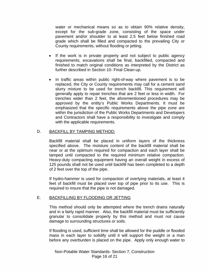
water or mechanical means so as to obtain 90% relative density, except for the sub-grade zone, consisting of the space under pavement and/or shoulder to at least 2.5 feet below finished road grade which shall be filled and compacted to the prevailing City or County requirements, without flooding or jetting.
• If the work is in private property and not subject to public agency
requirements, excavations shall be final, backfilled, compacted and finished to match original conditions as interpreted by the District as further described in Section 10- Final Clean-up.
• In traffic areas within public right-of-way where pavement is to be
replaced, the City or County requirements may call for a cement sand slurry mixture to be used for trench backfill. This requirement will generally apply to repair trenches that are 2 feet or less in width. For trenches wider than 2 feet, the aforementioned procedures may be approved by the entity’s Public Works Departments. It must be emphasized that the specific requirements above the pipe zone are within the jurisdiction of the Public Works Departments and Developers and Contractors shall have a responsibility to investigate and comply with the applicable requirements.
D. BACKFILL BY TAMPING METHOD:
Backfill material shall be placed in uniform layers of the thickness specified above. The moisture content of the backfill material shall be near or at the optimum required for compaction and each layer shall be tamped until compacted to the required minimum relative compaction. Heavy-duty compacting equipment having an overall weight in excess of 125 pounds shall not be used until backfill has been completed to a depth of 2 feet over the top of the pipe. If hydro-hammer is used for compaction of overlying materials, at least 4 feet of backfill must be placed over top of pipe prior to its use. This is required to insure that the pipe is not damaged.
E. BACKFILLING BY FLOODING OR JETTING
This method should only be attempted where the trench drains naturally and in a fairly rapid manner. Also, the backfill material must be sufficiently granular to consolidate properly by this method and must not cause damage to surrounding structures or soils. If flooding is used, sufficient time shall be allowed for the puddle or flooded mass in each layer to solidify until it will support the weight or a man before any overburden is placed on the pipe. Apply only enough water to
Non-Potable Water Standards- Section 7, Construction Page 16 of 21
give complete saturation of the backfill material. Drain off excess water or it will retard the drying and consolidation of the materials. Flooding, if used, shall be applied after pipe zone material placed. However, to prevent floating the pipe at a minimum, some material should be placed adjacent to and over the pipe to add weight. In the pipe zone, the backfill material shall be placed in uniform layers of the thickness specified above. At the top of each layer, the trench shall be diked at suitable intervals depending on the slope, and the trench between dikes shall be filled with sufficient water to inundate the backfill materials. Visual inspection of the backfill must indicate settlement prior to placing the next layer of fill. Care shall be exercised to prevent floating the pipe. Following the backfilling of the pipe zone, the trench shall be filled in uniform layers not to exceed 18” in thickness. Each layer of fill will be diked at suitable intervals depending upon the slope, and the area between the dikes flooded with water at repeated time intervals until the backfill is completely saturated. Visual inspection of the backfill must indicate settlement prior to placing the next layer of fill. The final layer shall also be saturated and after settlement occurs the surface will be prepared for final dressing or paving. Jetting with water to saturate the trench backfill layers is an acceptable alternate to flooding. Jet holes shall be a maximum of 10 feet apart and sufficient water should be applied to consolidate the backfill materials. Also, care must be taken not to push the jetting pipe down below the spring line of the pipe, causing disturbance to the pipe grade. Also, the materials should be jetted from the bottom upwards.
F. COMPACTION TESTS:
These tests shall be taken as determined by the District. The Developer/Contractor shall make all necessary excavation for the tests at locations selected by the District, and shall refill and re-compact these excavations to the specified densities.
7.15 RESURFACING AND RESTORATION
If the non-potable water work shall occur in the streets where no paving exists, the Contractor shall, in accordance with the City and County requirements, leave the completed trenches in a suitably compacted condition for finish grading, placement of base material and paving by others. If the work is within existing City or County streets, any required surfacing shall be in accordance with the City or County encroachment permit. Plate W-11 is included as information.
Non-Potable Water Standards- Section 7, Construction Page 17 of 21
If the work has disturbed or damaged existing private streets, alleys, driveways or other improved surfaces, the damaged portions shall be removed and restored, including the provision of adequate sub-grade where these operations have disturbed the original material… Substructures removed or damaged on public or private property shall be restored or replaced unless such structures are designated on plans “to be abandoned”. Such structures include but are not limited to trees, bushes, plantings, ground cover, mailboxes, fences and sprinkler systems. Any temporary paving, the Contractor as required shall furnish barricades or special provisions required by public agencies.
7.16 BORING AND JACKING OPERATIONS
A. GENERAL:
Placement of pipe by boring or jacking methods requires special District approval for each instance. However, as a general guideline, the following shall pertain: 1. Except for the use of air or water, the methods and equipment used
in Boring and jacking operations shall be optional to the Contractor provided that the District reviews them prior to work.
2. The placement of pipe shall be to the lines and grades shown on the plans.
3. Voids remaining outside the pipe (or carrier pipe if applicable) shall
be backfilled with concrete.
4. Where a casing is used, it shall be no less than 8” greater in diameter than the pipe to be installed.
5. The placement of pipe in casing shall be supported with redwood
skids, shims or wedges to the lines and grades as shown on the plans.
B. BORES:
The boring machine shall cut a true circular bore to the required line and grade. The bored tunnel shall be no more than 2” larger in diameter than the maximum outside diameter of the casing or water pipe to be installed.
C. JACKED STEEL CASING:
Non-Potable Water Standards- Section 7, Construction Page 18 of 21

In addition to applicable sections above, the following shall pertain: 1. Where casings are used, the size and wall thickness of the casing shall
be at the Contractor’s option except that the minimum casing thickness shall be not less than 3/8”.
2. Field joints of steel casings shall be welded with a continuous
circumference weld.
3. The placement of pipe in casings shall be supported with redwood skids, shims or wedges to the lines and grades shown on the plans.
4. Prior to backfilling the annular space between the pipe and casing, the
pipeline shall be tested in accordance with Section 9, Testing.
5. The annular space shall be backfilled with washed concrete sand blown or rammed into place until the entire cavity is filled. Concrete bulkheads shall be placed at each end of the cased section to retain the backfill material.
7.17 CONCRETE AND MORTAR WORK
Concrete used for encasements, filling, blocking, piers and other typical water construction applications shall be transit- mixed concrete from a supervised batch plant that issues certified delivery tickets with each load, showing the mix proportions, mixing time, truck departure time and water added. Such certified tickets will be handed to the Inspector at the time of delivery. Ready-mixed concrete shall be batched and handled in accordance with ASTM C94. Job mixed concrete shall be limited to that needed for patching and minor non-structural uses requiring one sack of cement or less. In these cases, the materials and workmanship shall be the same as if transit-mixed concrete had been used. The 28-day shall be applied in such a manner as to assure an even, smooth, uniformed adhering coat free from dirt, runs, brush marks and laps, and shall be applied as recommended by the manufacturer.
7.18 PAINTING
Painting will not be permitted when freshly painted surfaces may become damage by rain, fog or condensation or when inclement weather can be anticipated. The Contractor at his expense shall replace fresh paint damage by the elements. Drop cloths shall be used to protect floors, equipment, piping and other exposed surfaces from spattering and spillage. Paint shall be allowed to dry thoroughly between applications of successive coats. The manufacturer’s recommended time between coats will be used as a guide by the Inspector as to
Non-Potable Water Standards- Section 7, Construction Page 19 of 21
when the next coat of paint may be applied. The District must give approval before successive coats are applied, unless otherwise approved.
The Contractor shall notify the District after surface preparation and after the application of each successive coat of paint. Spray painting will not be permitted unless specifically authorized by the District.
7.19 SAFETY
Wherever the Contractor is aware of unsafe operations, such operation should be discontinued immediately. Also, if the Inspector is aware of such conditions and informs the Contractor of same, it will be the Contractor’s responsibility to comply. In such instances, the advice shall not be construed as implying any District liability. Essential to proper safety is adherence to all traffic control requirements. Contractor is to submit to the District a copy of their annual CAL-OSHA permit and the letter notifying CAL-OSHA of their work on the District project.
7.20 SIGNAGE
A sign reading "Non-Potable Reclaimed Water-Not for Drinking" in English and Spanish, shall be posted at all points where consumption of the water may be attractive to the public, tradesmen, and employees (yard hydrants, hose bibbs, etc.), in areas of public use that receive reclaimed water, and at all valves, control boxes, and similar features. This requirement may also apply to sprinkler heads when after-market clip-on purple rings are readily available. Signs reading "This Facility is Irrigated with Reclaimed Water-Not for Drinking" shall be posted at conspicuous locations in areas irrigated with reuse water; where signage is not feasible (such as a valve box in a street), the above wording shall be engraved on brass tags riveted to the outside and inside of the component. A signage plan shall be submitted to the District and approval for it obtained from the District before connecting to the District’s reuse water system. These signage provisions apply to both new construction and cases where an existing irrigation water line is connected to the District’s reuse water system.
To the extent practical, reuse components shall be painted purple, (for example: valve box lids, valves, valve operators, control boxes, etc.).
Non-Potable Water Standards- Section 7, Construction Page 20 of 21
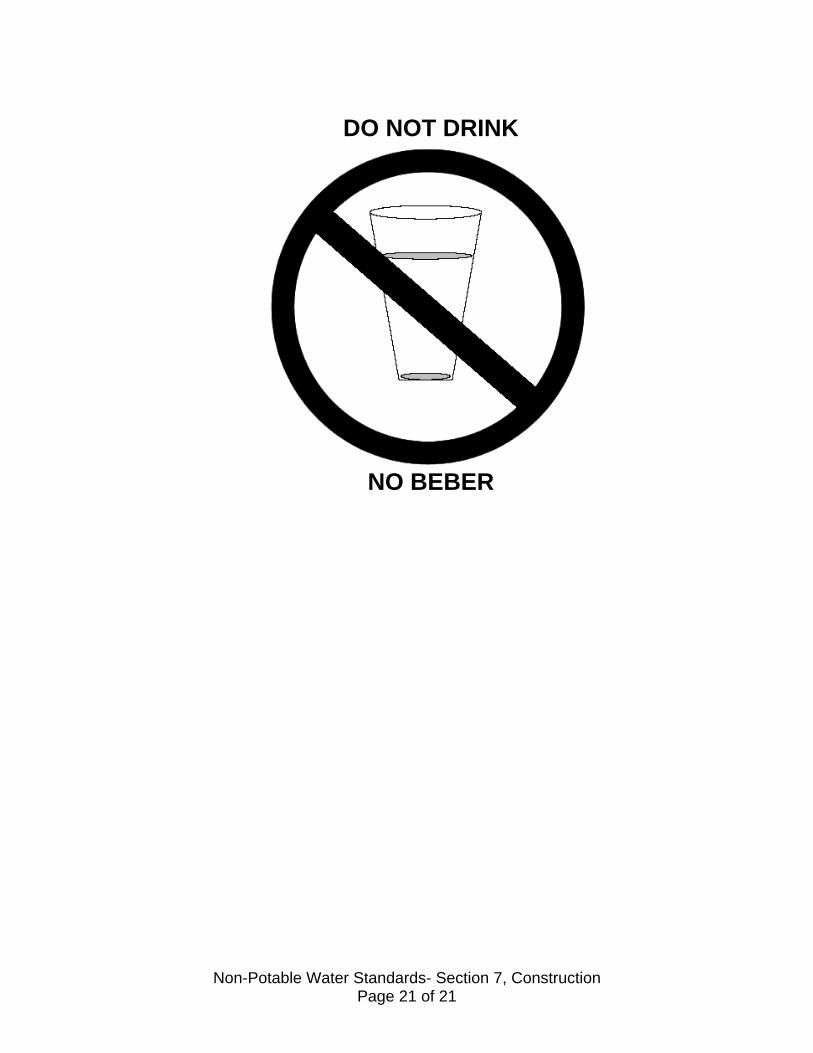
DO NOT DRINK
NO BEBER
Non-Potable Water Standards- Section 7, Construction Page 21 of 21

SECTION 8
ABANDONMENT 8.1 GENERAL
The Developer’s Engineer shall indicate all existing non-potable waterlines or structures that are to be abandoned, on the drawings. In general, abandoned lines that are in service will be replaced with a parallel line of equal or larger size, and the Engineer shall demonstrate in any case that the abandonment does not adversely affect the water system.
All abandonment and construction techniques shall be discussed with the District Inspector and approved prior to any such work. 8.2 NON-POTABLE WATER LINES
Non-potable water lines to be abandoned shall be entirely filled by pumping concrete into them. The pump mix shall be a mixture sufficiently workable for the purposes intended and shall be a concrete mix of 2,000 psi minimum. The Engineer shall show on the drawings the approximate number of cubic yards of concrete that will be required for any particular reach.
8.3 STRUCTURES
Structures associated with lines to be abandoned shall be removed by the Contractor/Developer and given to the District if salvageable.
Non-Potable Water Standards- Section 8, Abandonment Page 1 of 1
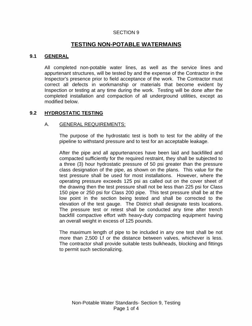
SECTION 9
TESTING NON-POTABLE WATERMAINS
9.1 GENERAL
All completed non-potable water lines, as well as the service lines and appurtenant structures, will be tested by and the expense of the Contractor in the Inspector’s presence prior to field acceptance of the work. The Contractor must correct all defects in workmanship or materials that become evident by Inspection or testing at any time during the work. Testing will be done after the completed installation and compaction of all underground utilities, except as modified below.
9.2 HYDROSTATIC TESTING
A. GENERAL REQUIREMENTS:
The purpose of the hydrostatic test is both to test for the ability of the pipeline to withstand pressure and to test for an acceptable leakage. After the pipe and all appurtenances have been laid and backfilled and compacted sufficiently for the required restraint, they shall be subjected to a three (3) hour hydrostatic pressure of 50 psi greater than the pressure class designation of the pipe, as shown on the plans. This value for the test pressure shall be used for most installations. However, where the operating pressure exceeds 125 psi as called out on the cover sheet of the drawing then the test pressure shall not be less than 225 psi for Class 150 pipe or 250 psi for Class 200 pipe. This test pressure shall be at the low point in the section being tested and shall be corrected to the elevation of the test gauge. The District shall designate tests locations. The pressure test or retest shall be conducted any time after trench backfill compactive effort with heavy-duty compacting equipment having an overall weight in excess of 125 pounds. The maximum length of pipe to be included in any one test shall be not more than 2,500 Lf or the distance between valves, whichever is less. The contractor shall provide suitable tests bulkheads, blocking and fittings to permit such sectionalizing.
Non-Potable Water Standards- Section 9, Testing Page 1 of 4

B. PREPARATION:
The lines shall be filled with water at least 24 hours prior to testing; this allows the pipe material to become saturated. During this period no pressure need be maintained on the line although some pressure, say 50 psi, will help to saturate the line and remove the air. While filling and immediately prior to testing, all air shall be expelled from the pipeline and whenever practical, water should be introduced from the low end of new system to facilitate the elimination of air in the pipeline and whenever practical, water should be introduced from the low end of new system to facilitate the elimination of air in the pipeline prior to testing. Where air valves or other suitable outlets are not available for releasing air for applying the test, approved taps and fittings shall be installed and later securely plugged.
C. PROCEDURE:
The pipeline pressure shall be pumped up to the specified test pressure. Then the pumping shall be pumped up to the specified test pressure. Then the pumping shall be discontinued until the pressure in the line has dropped 10-15 psi, at which time the pressure shall again be pumped up to the specified test pressure. This procedure shall be repeated until 4 hours have elapsed from the time the specified test pressure was first applied. At the end of this period, the pressure shall be pumped up to the test pressure for the last time.
D. LEAKAGE:
Shall be considered as the total amount of water pumped into the pipeline during the three (3) hour period, including the amount required in reaching the test pressure for the final time. Leakage shall not exceed the rates given in the Table below. If leakage exceeds this rate, the weak points shall be located and stopped, and all defective pipe, fittings, valves and other accessories discovered shall be removed and replaced with sound material and test shall be repeated until the leakage test is passed. All perceptible leaks shall be similarly repaired.
E. STEEL PIPE:
Steel pipe with mortar lining has the same requirement for a minimum soaking period. However, assuming 40 standard lengths, the leakage allowance is lower as seen in the following Table:
Non-Potable Water Standards- Section 9, Testing Page 2 of 4

TABLE 9-1
ALLOWABLE LEAKAGE FOR 3 HOURS PER 1,000 LF OF PIPE**
Pipe Size Test @200 PSI Test @250 PSI 8” 1.5 gal 1.7 gal 10” 1.9 gal 2.2 gal 12” 2.3 gal 2.6 gal 14” 2.7 gal 3.0 gal 16” 3.1 gal 3.4 gal 18” 3.5 gal 3.9 gal
** Based upon L= ND P divided by 7400 where L= leakage in gal/hr; N= # of joints P= test pressure in psi Of course, where the joints are welded, there should be no leakage allowance.
F. PVC PIPE DIFFERENCES:
The soaking period requirement is not critical for PVC pipe since the walls do not absorb water and become saturated. Although AWWA Manual M23 recognizes a two (2) hour leakage and pressure test, the District requires the same three (3) tests for PVC and steel. Since the standard joints are 20 feet long instead of steel’s 40 feet, the leakage allowance is twice that given in Table 9-2.
G. DUCTILE IRON PIPE DIFFERENCES:
As with PVC pipe, the soaking period is not critical unless the pipe is mortar lined. Then the minimum 24 period is required. A three (3) hour pressure test shall be used and the limits will be 2.2 times the values in Table 9-2 assuming lengths of pipe are 18 feet instead of the 40 feet the Table was set up for. If using 20-foot lengths of pipe, the allowance is twice that in Table 9-2.
H. POSSIBLE CAUSES FOR TEST FAILURES:
For information, the following is provided:
1. Dirt of foreign material under the coupling gasket. 2. Pipe not sufficiently covered in trench.
Non-Potable Water Standards- Section 9, Testing Page 3 of 4
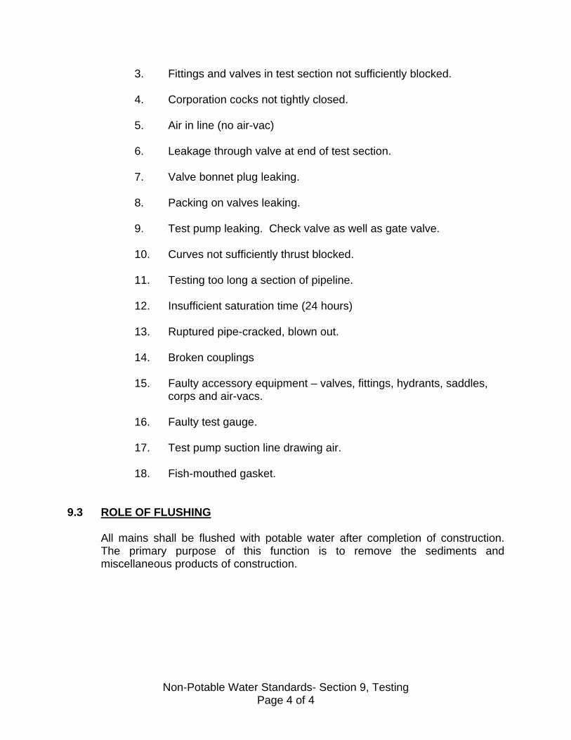
3. Fittings and valves in test section not sufficiently blocked.
4. Corporation cocks not tightly closed.
5. Air in line (no air-vac)
6. Leakage through valve at end of test section.
7. Valve bonnet plug leaking.
8. Packing on valves leaking.
9. Test pump leaking. Check valve as well as gate valve.
10. Curves not sufficiently thrust blocked.
11. Testing too long a section of pipeline.
12. Insufficient saturation time (24 hours)
13. Ruptured pipe-cracked, blown out.
14. Broken couplings
15. Faulty accessory equipment – valves, fittings, hydrants, saddles, corps and air-vacs.
16. Faulty test gauge.
17. Test pump suction line drawing air.
18. Fish-mouthed gasket.
9.3 ROLE OF FLUSHING
All mains shall be flushed with potable water after completion of construction. The primary purpose of this function is to remove the sediments and miscellaneous products of construction.
Non-Potable Water Standards- Section 9, Testing Page 4 of 4

SECTION 10
NON-POTABLE WATER SYSTEM AND WORK AREA CLEAN-UP 10.1 FINAL PROJECT CLEAN-UP
Once all pipeline systems have been installed, pressure tested and flushed, the system can be field accepted, providing the necessary clean-up has occurred. All structures shall be properly painted, where required, and free from dirt, concrete or other spattered materials. Also, the Contractor will clean the work site of construction debris. All private improvements damaged during construction shall be restored to at least the original condition of said improvements including but not limited to trees, shrubs, gutters, sidewalks, fences, grass, etc. Filled excavations in private property shall be neatly finished in a manner to facilitate natural drainage and eliminate hazards to persons or property. Also, all requirements of the District, the City and/or County Public Works Department, as appropriate, shall have been met. The project shall be left in a final condition that brings no discredit to the District.
Non-Potable Water Standards- Section 10, Clean-up Page 1 of 1

SECTION 11
REQUIREMENTS FOR FINAL ACCEPTANCE
11.1 GENERAL
“Acceptance” of a project by the District really occurs in several stages. In this regard, there are several appropriate terms associated with acceptance: A. FIELD ACCEPTANCE:
This is the term used when the District Inspector inspects the project and agrees that all requirements as shown on the approved drawings and as specified in these Standards have been met.
B. FINAL ACCEPTANCE:
This is the term used when the Board formally accepts the water system by a majority vote.
11.2 FIELD ACCEPTANCE
After satisfactory completion of the improvements, the District Inspector will provide a field acceptance letter to the Engineering Services Manager. However, it shall be the Developer’s responsibility to initiate action and to supply the required administrative items prior to official District Board acceptance of improvements.
11.3 “AS-BUILT” ORIGINALS
Original “As-Built” drawings and two (2) sets of blue-line prints shall be submitted to the District. The “As-Built” shall reflect the actual improvements made and give the accurate location of all new/or relocated facilities. The following certificates shall be signed and shall be signed and shall appear on the cover sheet of the water plans.
AS-BUILT CERTIFICATE
I hereby certify that the work shown on Drawing No. ________, Sheets No. _____through ______ marked ‘As-Built” has been constructed in conformance with lines and grades and requirements as shown on said plans, drawings and referred specifications. ________________________________ ___________ __________ Registered Civil Engineer Number Date
Non-Potable Water Standards- Section 11, Acceptance Page 1 of 3

It should be emphasized that the responsibility for accurate “As-Built” drawings must involve active participation by the Developer’s Engineer during the project construction. All changes, whether done through the formal change order or revision process or whether done, as field adjustment should be reflected on the “As-Built” drawings.
11.4 NOTICE OF COMPLETION
The Developer shall submit a copy of the recorded notice of the completion of the water system to the District.
11.5 GRANT DEED
The Developer shall submit the original unrecorded “Grant Deed” executed by the Developer conveying the system to the District; this includes notarization of all signatures. Language to be used on Grant Deed is as follows: “ An Easement and Right-of-Way to lay, construct, repair, maintain, operate, renew, replace pipeline and appurtenances incidental hereto for the transportation of non-potable water with the right of Ingress and Egress to and from same in, over, under and across the easement and with the right to disturb the surface of the easement area. Replacement or repair of improvements, including landscaping that are disturbed, damaged or destroyed by the District in exercising the above-described rights, will be the responsibility of the servient tenement, who shall bear the full cost, unless otherwise stated herein”.
11.6 ITEMIZED COST OR ADDITIONAL FEES
A certified and itemized copy of the cost of the facilities offered for dedication shall be submitted. Such certification shall consist of copies of the signed contractual agreement with any change orders. If the final cost is found to be more than the originally approved Engineer/s cost estimate, Developer shall pay the District an additional amount of Plan Check and Inspection Fees.
11.7 OTHER ADMINISTRATIVE ITEMS INCLUDING EASEMENTS
Depending upon the project, there can be other Administrative items required before final Acceptance. Examples are unpaid invoices, contractual requirements involving easements, etc.
11.8 FIFTY PERCENT OCCUPANCY
District Board can process the acceptance items after fifty percent of the Development has been completed and occupied.
Non-Potable Water Standards- Section 11, Acceptance Page 2 of 3

11.9 APPROVAL FOR ACCEPTANCE
When all requirements (field and administrative) have been met, staff will prepare a resolution recommending Board acceptance of the improvements and exoneration of the Performance Bonds and Labor and Materials Bonds (10% of the bonds remains in force until it is fully exonerated; generally this is for the one- year maintenance and guarantee period). Whereas, the normal maintenance and guarantee period is one year and the bond retention is 10% of the final cost of construction; both of these may be increased if in the opinion of the District, the normal period and amount are not sufficient.
11.10 STATUS DURING MAINTENANCE AND GUARANTEE PERIOD
The Developer/Contractor is responsible, during the guarantee period, for the proper maintenance of the water system. Should the District’s crew have to perform any of this work, the costs for it may be invoiced to the Developer /Contractor.
11.11 EXONERATION OF SURETY
Ninety Percent (90%) of the final cost of the development will normally be exonerated upon acceptance by the District. Ten percent (10 %) will be retained for the one-year guarantee period and then released.
Non-Potable Water Standards- Section 11, Acceptance Page 3 of 3