nondestructive measurement of residual stress · waoo-tm42. qd-.2,q'? oil study of ultrasonic...
TRANSCRIPT
WAOO-TM42. qD-.2,q'? Oil
STUDY OF ULTRASONIC METHODS FOR NONDESTRUCTIVEMEASUREMENT OF RESIDUAL STRESS
TECHNICAL DOCUMENTARY REPORT NO. WADD-TR-61-42, Pt. II
January 1963
Directorate of Materials and Processes
Aeronautical Systems DivisnionAir Force Systems Command
Wright-Patterson Air Force Base, Oio
(0
NProject No. 7360, Task No. 736002 CqJ
C)
(Prepared under Contract No. AF 33(616)-7058 by 0Midwest Research Insitute, Kansas Cty, Mo.;
Fred R. RoWuu Jr., Donald R. Kaott, and CMJJerry Lee Jons, Autos)

NOTICES
When Government drawings, specifications. or other data are used for anypurpose other than in connection with a definitely related Government procure-ment operation, the United States Government thereby incurs no responsibilitynor any obligation whatsoever; and the fact that the Government may haveforuiwlated, furnished, or in any way suppliedthe said drawings, specifications,or other data, is not to be regarded by implication or otherwise as in anymanner licensing the holder or any other person or corporation, or conveyingany rights or permission to manufacture, use, or sell any patented inventionthat may in any way be related thereto.
Qualified requesters may obtain copies of this report from the ArmedServices Technical Information Agency, (ASTIA), Arlington Hall Station,Arlington 12, Virginia,
This report has been released to the Office of Technical Services, U.S.Department of Commerce, Washington 25, D.C., in stock quantities for saleto the general public.
Copies of this report should not be returned to the Aeronautical SystemsDivision unless return is required by security considerations, contractualobligations, or notice on a specific document.
B
FOREWORD
This report was prepared by Midwest Research Institute under USAFContract No. AF 33(616)-7058. The contract was initiated under Project No.7360, "The Chemistry and Physics of Materials," Task No. 73602,9 "NondestructiveMethods." The work was administered under the 'Directorate of Materials andProcesses, Deputy for Technology, Aeronautical Systems Division, ritb Mr. R. R.Rowand acting as project engineer.
This report covers work conducted from 1 February 1961 to 31 January1962.
The work was performed under the direction of Mr. Fred Rollins, Jr.Personnel directly involved in prosecution of the research have been Messrs.Jerry Jones, Donald Kobett, Neil Abbott, James Gravitt, Paul Gutshall, andPhillip James.
ABSTRACT
The study of streas-induced birefringence has been continued in bothpolycrystalline and single crystal experiments. The effect is explained on thebasis of nonlinear elasticity theory. Experiments indicate that dislocationactivity does not strongly affect results in polycrystalline specimens, however,a pronounced influence may be observed in single crystals.
Nonlinear elasticity theory has been used to investigate the inter-action of two intersecting, plane, elastic waves in a homogeneous, isotropicmedium. A criterion for the occurrence of a strong scattered wave has beenderived. The criterion is formulated as a relationship between the secondorder elastic constants of the material, the angle between the intersectingwave vectors, and the ratio of primary wave frequencies. The amplitude of thescattered wave is found to be proportional to the volume of interaction anddependent on the third order elastic constants of the material. Preliminaryefforts to experimentally verify the theoretical predictions are described.
This report has been reviewed and is approved.
W. J. TRAPPChief, Strength and Dynamics Branch'4etals and Ceramics LaboratoryDirectorate of Materials and Processes
iii
TABLE OP CONTENTS
PAGE
I. INTRODUCTION .................. . .. . 1
II. STRESS-INDUCED BIREFRINGENCE ............... 1
A. GENERAL DISCUSSION .................. 1B. PREDICTIONS BASED ON THEORY OF FINITE STRAIN . . . .. 2C. EXPERIMENTAL RESULTS . . ............... 5
III. ULTRASONIC BEAM INTERACTION IN SOLIDS . . . . . . . . . . . 10
A. THEORY . . . . . . . . . . . . . . . . . . ...... 10B. PRELIMINARY EXPERIIuNTS . . . . . I........... 11
IV. SU4M ............... ... ...... 14
APPENDIX I - THE INTERACTION OF ELASTIC WAVES IN ANISOTROPIC SOLID . . . ......... . . . . . . . 15
iv
I. INTRODUCTION
In recent years considerable effort nas been directed toward the de-tection and measurement of residual stre-ýs. Most of the methods that havebeen successfully developed are destructive or semidestructive in nature. Thesemethods, in general, are based on the fact that relieving the stresses will al-ter the dimensions of the body. Successive sections of the test piece are re-moved by chemical or mechanical means ard the strain relaxation that occurs inthe remaining material is measured. The stress distribution is then calculatedfrom the strain distribution found in the metal specimen.
The only nondestructive method that is successfully used in measur-ing residual stresses is one which utilizes X-ray diffraction techniques. Eventhis method has a number of disadvantages. Good accuracy is obtained only withspecimens that yield sharp diffraction lines. Quenched steels or cold workedmetals give diffuse lines that produce very large errors. An even greater lim-itation is that only surface stresses can be investigated using this method.
During the past two years Midwest Research Institute has been engagedin a study of the stress-dependent aspects of ultrasonic propagation in solidmaterials. It is hoped that the results of this study may facilitate the ap-plication of ultrasonics to specific residual stress problems. An earlier re-portl/ covers the first year's work and snould be consulted for experimental de-tails that have been intentionally omitted in the following discussion.
II. STRESS-INDUCED BIREFRINGENCE
A. General Discussion
It has been recognizfd for some time that the velocity and attenua-tion of ultrasonic waves traveling through solid materials are usually stress-dependent. The exact nature of these stress-dependent changes is not completelyunderstood but recent advances in dislocation theory and finite elasticity canexplain many of the experimental observations.
A property that we have studied in several solids is the stress-in-duced double refraction of megacycle shear waves. In a rectangular coordinate
Manuscript released by authors February 1962 for publication as a WADDTechnical Report.
1
system, let us consider a shear wave traveling in the x-direction. If the ma-
terial is isotropic, we will find that the shear wave velocity is independent
of the direction of particle motion. However, if we remove the isotropy by
applying a tensile stress in the y-direction, the velocity is found to vary
with the direction of particle motion. Under these conditions it is impossible
to propagate a plane polarized shear wave except when the particle motion is
either parallel or perpendicular to the applied stress. Referring to the above
two velocities as VS1 and VS2 respectively, we can define a fractional ve-
locity difference, (AV/V) = (V3I-Vs 2 )/V , where V is an average of VS1 and
VS2 . The value of AV/V can be determined experimentally using a simple pulse-
echo technique.!/ It has been well established that the AV/V. values are
stress-dependent and, in fact, vary linearly with the stress level. The cor-
relation between theory and observation is described in the following two sec-
tions.
B. Predictions Based on Theory of Finite Strain
The velocities of longitudinal and shear waves in an isotropic, homo-
geneous medium are usually given by the following expressions:
VL= 1VS=, (1)
where X and Ii are the second order Lame' constants and P is the density.
These expressions are derived on the basis of infinitesimal deformations. They
do not predict a stress-dependent velocity so long as the density remains con-
stant. However, by using the finite strain method of Murnaghan,2/ Hughes and
Kelly_/ calculated the velocities of ultrasonic waves in isotropic media and
obtained the stress-dependent expression shown below:
(a) For hydrostatic pressure, p
Longitudinal wave POVL = (2p+X) -P !Oi,+7X+6t+4m1 (2)3K El
Shear wave P-S=U -j L3(2u+X)+3m (3)
2

(b) Uniaxial Pressure, P , and wave propagation both in x-direction
Longitudinal wave PoVL = (21,+X) -P [11[+1 (1Ou+4X+4m)+X+2t] (4)
V 11 _ P [4(1g+x) + X4.• n +m (5)
Shear wave POV=p -S4p M]
(c) Uniaxial Pressure, P , iJn x-direction vath wave propagation in y-direction
Longitudinal wave PoVT2= (20+X) _ P [2t _ 2X (24+Xn)] (6)
Shear wave with
particle motion pvl = P - 2+X+m+ L ni (7)in x-direction 3K 4p
Shear wave withparticle motion = p - [m-2% n] (8)in z-direction
In these expressions, p0o is the density of the undeformed medium, K is thebulk modulus and the terms t , m , and n are referred to as third orderelastic constants. The latter give an indication of the nonlinearity in theelastic behavior of a material. It is easily seen that when the hydrostaticpressure or uniaxial stress is zero the expressions all reduce to the two ex-pressions given in (1).
The three third order constants that appear in expressions (2)-(8)can, of course, be determined experimentally by accurately measuring the ve-locity changes produced in at least three independent cases. It is possibleto independently determine the third order constant, n , by a simple techniquethat does not necessitate the accurate measurement of absolute velocity. Whenihear waves are sent through a specimen in a direction that is perpendicularto the direction of an applied uniaxial stress, expressions (7) and (8) in-
dicate that the velocity depends upon the particle motion direction. The in-
itially isotropic material becomes birefringent. Pure shear waves can be
propagated in this case only when the particle motion is either parallel or
3

perpendicular to the applied ±oaa. If we subtract expression (8) from (7) andremember that K = 1/3(2t+3X) , we get
0V-2 2 P0 Sl PoS2.1 L 4in (9)
Since V + V 2Vo , ve then have
801o ++ V3 (i0)3
or expressed as a fractional difference
ysl-VS 2 = - [+nl] P L [4,+n] (11)Vo 8 PoV2ýL 8P2
From (ii) we see that the fractional difference between VS, ana VS2 is alinear function of the uniaxial stress, P . Note also that experimental deter-mination of AV/V at a given stress is sufficient to evaluate the third orderconstant, n .
The velocity of ultrasonic waves in single crystals is also stress-dependent, but the velocity expressions are somewhat more involved due to theloss in symmetry. Seeger and Buck'/ have derived the differential equationsfor wave propagation in cubic crystals that have superimposed finite stresses.There are six third order elastic constants for such crystals and Batemanet al.,2/ have recently used ultrasonic techniques to evaluate all of theseconstants for germanium. The velocity expression given in Ref. 5 for a shearwave traveling in the L001] direction with particle motion parallel to a [11•1pressure is as follows:
WII= (li-Y+(.-O)C 44 + [(c.+f)/4] C144 + [( a+8+2Y)/4] C166
+ [(C-0/4] C4 ,5 6 *(12)
4
For a shear wave traveling in the same direction but with particle motion per-pendicular to [1103 , the expression is
PVJ_ = (l+Y+53-a)C44 + [(a.+i3)/4] C144 + [(0'+0+2y)/4] C166
+ [0i-ci0/4] C456 - (15)
In the above expressions a , 3 , and Y are all linear functions of the ap-plied stress and the Cijk terms are the third-order moduli. By using theapproximation (Vll + V_ ) a- 2V , the fractional velocity difference for shearwave propagation in the [OO] direction becomes
V - C2 (4c 4 4 +c456 ) • (14)8C44
Here again we see that the fractional velocity difference is a linear functior.of the uniaxial stress P .
It should be emphasized at this point that the above expressions,(2)-(8) and (12)-(13), were derived for a perfectly elastic material. For mostreal mi;erials, an applied stress will produce some anelastic strain in addi-tion to the elastic strain. Granato and LIicke6,7/ have developed a theory ofenergy losses and modulus changes that are due to dislocation damping. Thetheory is based on the model of a dislocation loop oscillating under the in-fluence of an applied stress. Without going into the details of this theory,it is sufficient to state that the fractional velocity change due to the dis-locations is proportional to the dislocation density and the second power ofthe dislocation loop length. There is considerable experimental evidence thatsupports the Granato-Liicke theory and there is no question that dislocationsdo affect the propagation of ultrasonic waves. Additional discussion of thissubject may be found in the following section.
C. Experimental Results
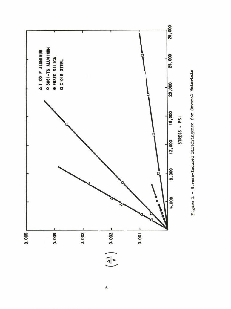
xne pulse-echo techniquel/ has been used to measure stress-induced!hanges of (AV/V) in a variety of materials. Figure 1 shows some typicalurves qnd confirms the linear relationship between (AV/V) and stress level.
5
I Ij§
aces
0Sf+4)
13
4oC1
8
It was mentioned previously that the (AV/V) measurements might be used toevaluate the third order elastic constant, n . We see from Eq. (11) that a plotof (AV/V) versus stress should yield a straight line with a slope of-(4ý+n)/8L2 . The slopes of the curves shown in Figure 1 have, therefore,been used to calculate n for each material and the results are summarizedin Table I.
TABLE I
Material n (psi)
6061-T6 AP.umnumr -(45.2 - 1.8) x 106
1100-F Aluminum -(69.2 + 5.5) x 106
C1018 Stec. -(83.1 + 4.4) x 106
Fucsed Silica -(33.2 + 0.9) x 106
It would be interesting to compare the values in Table I with those obtainedby other workers but we have been unable to find any third order data on thesespecific materials.
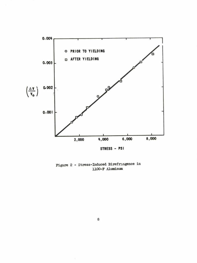
It has been previously reported2/ that (AV/V) for C1018 steelvaries linearly with elastic strain but is relatively insensitive to plasticstrain. This result suggests that the dislocation activitywhich occurs inthe plastic range, must affect VS1 and VS 2 by nearly equal amounts. Thus,(VSl-VS2) remains essentially unchanged. The variation of (AV/V) duringelastic and plastic deformation has more recently been studied in specimensof 11O0-F aluminum. The results have been very similar to those for steel.Figure 2 presents data for a specimen of 11O0-F aluminum both before and afteryielding. The first data were taken during the initial loading cycle. Thespecimen was then loaded beyond the yield point until a strain of approximately0.2 per cent was reached and then the second set of data was taken. The maxi-mum-minimum type pulse echo patterns, which are used in evaluating (AV/V) ,change continuously as the load varies but they do not appear to vary with timeat constant load. However, if the transducer is rotated so that the particlemotion is parallel or perpendicular to the compression, an exponential decaypattern is obtained and the attenuation is very time-dependent immediately fol-lowing load changes. The time-dependent variation in attenuation is apparentlydue to dislocations that break away from impurities and/or vacancies when thestress is varied. These point defects then diffuse through the lattice and
7
O .0 0 1 I
o PRIOR TO YIELDING
13 AFTER YIELDING0.003
(Lv) 0.002
0.001
2,000 4,0 ,000 8,000
STRESS - PSI
Figure 2 - Stress-Induced Birefzr-mn~ece in13O-00- Aluminiun
8
repin the dislocations as the load is held constant. In contrast, the lack oftime dependence in the stress-induced birefringence together with the agreementbetween pre-yield and post-yield values provide a strong indication that dis-locations have little effect on birefringence measurements in polycrystallinesteel or aluminum.
We have also studied stress-induced birefringence in single crystalsof high purity aluminum and sodium chloride. The results have been similar tothose obtained for polycrystalline specimens but somewhat less reproducible.There is an additional effect which one may encounter in working with singlecrystals and that is internal conical refraction. This effect occurs when shearwaves travel through a crystal in a direction that is not exactly parallel to"a specific crystal direction. Pure shear waves, for example, can travel through"a cubic crystal in the [100] direction and the velocity is independent of thepolarization angle. If, however, the propagation direction is slightly mis-oriented with respect to [100] , then internal conical refraction may occur.Waterman and Teutonicoi8/ have shown that this effect can produce pulse-echopatterns exactly like those used to evaluate stress-induced anistropy. Preciseorientation of the single crystal is very important then in shear wave studies,particularly at high frequencies. The technique of Walker and co-workersg/was used to orient and grind the mechanical faces of the specimen parallel toa desired crystal face. Subsequent hand lapping was necessary to attain theeven more stringent requirements on parallelism between opposite surfaces. Forpulse-echo work at frequencies between 10 and 100 mc. the parallelism should1e maintained to within 0.00005 in/in.
In addition to the problems outlined above, the single crystal experi-ments were influenced strongly by dislocation activity. In both aluminum andsodium chloride the shear waves were sent through the crystal along [I00]while compressive loads were applied in the [O01j direction. As the externalstress was applied to aluminum the (AV/V) values were observed to be bothstress dependent and time deperAent. Upon loading the specimen (AV/V) firstLncreased and then part of the increase was lost as time progressed at constantload. The equilibrium value, reached after a few minutes, was proportional tothe applied load. When the load was removed, (AV/V) momentarily increasedagain, but then decreased with time to the no load value. The equilibriumvalue after loading, however, was usually higher (indicating increased aniso-tropy) than Drior to loading.
in similar experiments on sodium chloride crystals the (AV/V) valueFwere more reproducible and less time dependent than for aluminum. The varia-tion is probably due to the different slip systems found in the two materials.Mhe primary slip system for aluminum is along (111) planes whereas sodium
9
chloride slips along (n10) planes. For pure shear waves traveling in a[iOdj direction there is no resolved shear stress across (110) planes butthere is a resolved stress across (1) planes. Thus, we see that a [i00]shear wave could interact with the many (111) dislocations in aluminum andyet exhibit no interaction with the (110) dislocations in sodium chloride.A change in (AV/V) due to dislocations "v!.uld only arise, however, from anan isotropic change in the distribution of dislocations. Such anisotropy ishighly probable in single crystals where slight changes in the direction ofstress application can activate more dislocation activity on some primary slipsystems than on others.
III. ULTRASONIC BEAM INTERACTION IN SOLIDS
A. Theory
The nondestructive measurement and analysis of a three-dimensionalstress distribution is a difficult problem to contemplate. It is obvious thatto succeed in this task one must monitor some prope•rty that is stress sensi-tive and must also localize the volume elements within the test specimen whichaffect the property being measured. Ultrasonic waves show some promise ofbeing successfully applied to this problem. In addition to certain stress-dependent aspects, ultrasonic waves can be collimated into well defined beams.The intersection of two collimated beams can be used to define a reasonably.small volume element within a relatively large metal specimen. Beam inter-action or scattering at the point of interaction might be related to stressesat the point of intersection. Whether;or not the beam interaction is stresssensitive is secondary, of course, to whether there is a detectable beam inter-action at all.
If one considers beam interaction based on linear elasticity theoryit is easily shown that the separate waves can each exist independently of theother, i.e., they do not interact. However, if the basic expression of elasticenergy is extended to terms cubic in strains the equations of particle motionthen contain quadratic terms in the displacements. The independent nature ofthe intersecting waves no longer holds and the theory admits the possibilityof interaction betmeen waves. An analysis of wave interaction in nonlinearsolids has been completed during the past year and the results are encourag-ing. A rather detailed description of the analysis is given in the Appendixso the results will be only briefly sumnmarized here.
The analysis considers the interaction of two waves in a hnmoetnous,isotropic solid. The results indicate that for a given material there does
10
exist an angle of intersection between two waves of frequencies wi and u2
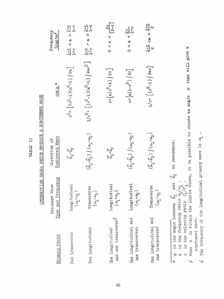
which produces a "resonant" interaction. Under resonant conditions the analysisindicates that scattered waves (with frequencies wI m+2 ) originate at the"point" of intersection. The analysis further predicts the direction of par-ticle motion as well as the propagation direction of the scattered wave. Theresonant angles of intersection and the directions of propagation for thescattered waves are summarized in Table II of Appendix I, p. 26.
Some calculations have also been made on the amplitude of the scat-tered wave. The amplitude is found to be proportional to the volume of inter-action and also dependent on the third order elastic constants of the material.A numerical example, based on data for polystyrene, indicates that the dis-placement amplitude of the scattered wave is not beyond the realm of detection.Nevertheless, the intensity of this wave will undoubtedly be small and optimumconditions must be obtained if detection is to be expected.
B. Preliminary Experiments
Experimental efforts to verify the wave interaction predictions arestill in the preliminary stages, but a description of the initial experimentis included here. The only case that has been examined experimentally is theinteraction of two transverse waves. From Table II of Appendix I, we see thatthe scattered wave in this case has a longitudinal mode and a frequency of(cl + w2 ) . The table also indicates that the angle for resonant interactionis
arc cos {C2 + [(C2_1) 1a+)/a
and that the direction of the scattered wave is (K,+K). We see, then, thatthe resonant angle depends only on the transverse to longitudinal velocityratio, C , and the frequency ratio, a , of the two primary waves. The direc-zion of the scattered wave is determined by the propagation vectors, KI andK2 , of che primary waves. It is further shown, in the numerical example ofkppendix I, that the amplitude of the scattered wave is a maximum when tI =W2 • Under these conditions, a wave of frequency 2w is predicted to emergein a direction that bisects the angle between the two primary waves. The anal-ysis also indicates that the two primary transverse waves should both be po-larized either parallel or perpendicular to the (-6, K) plane.
ll
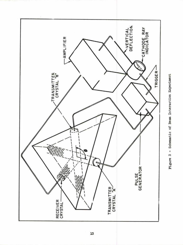
A schematic of the interaction experiment described above is shown
in Figure 3. The specimen was machined with the shape of an isosceles tri-
angle - the angle between the equal sides being cut so the two primary waves
would intersect at the resonance angle, $ . The scattered wave should then
travel normal to the third side of the triangular specimen. The two transducers
used to generate the primary waves were both 5 mc., AC-cut quartz crystals.
The receiving transducer was a l0-mc.x-cut crystal. The figure depicts the
ultrasonic wave packets after they have passed through the volume of inter-
action and the scattered wave is Just arriving at the receiver crystal. The
electrical signal from the crystal is fed to an amplifier tuned for 10 mc.,
and the amplified signal drives the vertical deflection plates of a cathode
ray indicator.
The transmitting crystals were first excited simultaneously with a
single 5-inc. signal from one pulse generator. Experiments were also performed
using two pulse generators. The two generators -were triggered at the same time
but the frequency of one could be varied slightly. This procedure was used to
possibly compensate for slight errors in both theory and experimental arrange-
ment that could cause the angle 0 to be in error. The compensation, of
course, was expected from changes in the frequency ratio (wi/w2 ) which affect*
the angle, 0 .
Judicious placement of the three crystals facilitates the detection
of the scattered wave by making it possible to distinguish the desired signal
from multiple reflections of the primary waves. From simple geometrical con-
siderations, it is easy to calculate the time of travel necessary to bring the
primary transverse waves to the intersection zone and the additional time re-
quired for the scattered longitudinal wave to travel to the receiver crystal.
It is then only necessary to use a scope with a calibrated sweep to localize
the desired signal. Multiple reflections of primary waves will arrive at the
receiver crystal much later than the scattered wave.
The interaction of two transverse waves has thus far been studied
only in fused silica and polycrystalline magnesium. We have not yet been able
to detect the predicted longitudinal waves, but several changes are being made
to optimize variables and increase sensitivity. An increase in the amplitude
of the primary waves and additional amplification of the received signals are
possible. Different specimen materials will be investigated to optimize non-
linear parameters. It is also desirable to operate at higher frequencies be-
cause the analysis indicates the amplitude of the scattered wave is dependent
upon the third power of the primary wave frequency. This factor, of course,
must be weighed against the increase in attenuation that occurs at the higher
frequencies.
12
400
Ir 0w w WC)
UU
C.)C-
U)3
Apparatus is also being assembled for the study of interactlut, oe-
tween one transverse wave and one longitudinal wave. This case has one advan-
tage over the transverse-transverse case in that the longitudinal wave can be
coupled into solid specimen through a liquid. This makes it much easier to
continuously vary the interacticn angle, 0 , and thus optimize the resonant
condition. A complete investigation of the interaction phenomena will inclu(..
numerous experimental arrangements using both pulsed and continuous wave tech-
niques.
IV. SUMARY
The study of stress-induced birefringence has been continued in both
polycrystalline and single crystal experiments. The effect is explained on the
basis of nonlinear elasticity theory. Experiments indicate that dislocation
activity does not strongly affect results in polycrystalline specimens, however,
i pronounced influence may be observed in single crystals.
Nonlinear elasticity theory has also been used to investigate the
interaction of two intersecting, plane, elastic waves in a homogeneous, iso-
tropic medium. A criterion for the occurrence of a strong scattered wave has
been derived. The criterion is formulated as a relationship between the first-
order elastic constants of the material, the angle between the intersecting
wave vectors, and the ratio of primary wave frequencies. The amplitude of the
scattered wave is found to be proportional to the volume of interaction and
dependent on the third order elastic constants of the material. Preliminary
efforts to experimentally verify the theoretical predictions are described.
14

APPENDIX I
THE INTERACTION OF ELASTIC WAVES IN AN ISOTROPIC SOLID
I. INTRODUCTION
In the linear theory of elasticity two elastic waves do not interact.The equations of motion are linear and therefore the principle of superpositionholds. Any solution of the equations of motion can be written as a linear com-bination of monochromatic waves. The linear theory of elasticity results fromassuming the elastic energy to be quadratic in the particle displacements. Ifterms cubic in the particle displacements are included in the elastic energy,the equations of motion become nonlinear.l_/ This nonlinearity gives rise toan effective interaction between two plane elastic waves which can producescattering. The scattering of two collimated, monochromatic, plane waves inan infinite isotropic solid is considered in the present paper.
II. THEORY
When terms cubic in the particle displacements are included in the-elastic energy, the resultant nonlinear equations of motion for an isotropic
solid are i_/
'U ri •2uI j
Po au a2U - (K+A/3) a =l(t a 2u axk axtoxi ~ j
(g+A/4) -+ _+2 Ak X
"+ (K+p,/3+A/4+B) aUA + au ui)axk axk x~k axL
/ 2u au au a2uAau+(K-2/3p+B) ( ~ - )+ A /B) Bxi+ a Lax -
"+ (B+2c)0) (I-i)
1.5
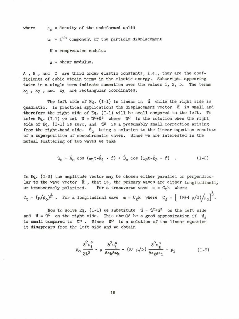
where Po = density of the undeformed solid
ui= ith component of the particle displacement
K = compression modulus
= shear modulus.
A , B , and C are third order elastic constants, i.e., they are the coef-
ficients of cubic strain terms in the elastic energy. Subscripts appearing
twice in a single term indicate summation over the values 1, 2, 3. The terms
x, , x2 , and x3 are rectangular coordinates.
The left side of Eq. (I-1) is linear in it while the right side is
quadratic. In practical applications the displacement vector id is small and
therefore the right side of Eq. (I-1) will be small compared to the left. To
solve Eq. (I-1) we set 'd = 'o+iUs where A° is the solution when the rightside of Eq. (I-1) is zero, and Ids is a presumably small correction arising
from the right-hand side. i1o being a solution to the linear equation consists
of a superposition of monochromatic waves. Since we are interested in themutual scattering of two waves we take
Uo =A o cos (wlt-kc1 • *) + 'o cos (w2 t-k -) . (1-2)
In Eq. (1-2) the amplitude vector may be chosen either parallel or perpendicu-lar to the wave vector '1 , that is, the primary waves are either longitudinallyor transversely polarized. For a transverse wave w = Ctk where
Ct = (p./po)½ . For a longitudinal wave w = Ctk where C = (K+4 ./3 o "
Now to solve Eq. (I-1) we substitute d = i0+ds on the left sideand d ='do on the right side. This should be a good approximation if !s
is small compared to TIO . Since Vo is a solution of the linear equationit disappears from the left side and we obtain
2s 2s 2sPo i - (K+ 13) pL i (1-3)
at2 - Xk•Xk xL3)xi
16

where the vector 11 is determined by putting 1o in the right side of Eq.(I-i). If we use Eq. (1-2) for 10o , P will involve a sum of products oftwo-monochromatic waves. Some of the terms will represent the interaction ofa primary wave with itself. This interaction has been treated before!2_/ andwe shall not include it here. Including only those terms representing inter-actions between the primary waves we find for 1 after some tedious manipula-tion
X(it,t) = f+ sin cJlw+w2 t-(t~l+ý) . 1
+ I- sin {(wl-w•)t-(1-1c) • (1-4)
where
.= -4 ( -,./,)- ., -o o)(k,-k.,)k
+ (Bolk)(k2k2A t (A'o-k(')~+( 0 )~~
±; 2(B0.k1)(k1 .-k2 } 2 2K/ / B
±X (K1/ + A/4)~ +B Ao-Bo (k% -)k_4 -..
± ~ 2)B~k~l - -fl (B+2C) f(A'O1')(' oý )ý2
±(Ao1k)(Bo~k2)k1
Since i is a known function of f and t , Eq. (1-3) is now a linear in-homogeneous equation for the scattered wave ts , with P acting as a sourceterm. Instead of writing Eq. (1-3) in component form we prefer to use vectornotation and write
17

(�,t) - C27 17.u(rt)I + C�x7xu (rt) = 4nq(�,t) (1-5)t
where 4Trq =
p0
This is the standard form for the inhomogeneous vector wave equation.i�i From
now on we shall be interested only in the scattered wave sp we shall drop the
superscript s until further notice. We introduce the time Fourier transform
pairs
+0
-w
+0
i�,t) = L f � 1wtu(�,w)dw
-0
p +0
From Eq. (1-5) the equation for the Fourier transform is
- w2�(�,w) - C�7t7.it(�,�)}+ C�7x7xi�,w) = . (1-7)
From Eq. (1-4) and Eq. (1-6) one finds that
�k {e�(�l�2 � 6(W+W1+W2) - e�(�L��2 )r(
I 6(w�wl+w 2)}+- e - e4ip0 V 6(w+wj-w2)
18

where 6(a) =0 for CL0
6(a) =c for ==0
and
COJ 6(x)d = i.
Now Eq. (1-8) is not quite right. We are interested in the casewhere the primary beams are wefl collimated. The interaction term I , whichis a product of the amplitudes of the primary beams, will be zero unless weare in the region where the primary beams intersect. We shall denote boththe region of intersection and i~s volume by V . Then Eq. (1-8) is validonly inside V and 4 is zero outside V .
If one assumes that tl(f,w) decreases at least as fast as i forr
large r , then it can be shownL'l/ that the solution for Eq. (1-7) in theinfinite region can be written as
U(r,w) =/G(-.P'w)4(P',w)dV (1-9,
where G is a tensor or dyadic operator. For the infinite region, G canbe written•1 /
(-r, 1) G, (it +/ L tf"C2 't_) Gwt) (I-10)
In Eq. (1-9) the term arising from G. will be longitudinal, whilethe term arising from Gt will be transverse. In dyadic notation G, andGt are given by__
19
(1-i W... /C =-i -2--R 2 i-BN
Gt(ri',w/C) -I e RR e e R2
2R 2 R 2 U2 (i-R)( 2 C2
T 2 iTRw2 R) i R
1- -2 R 2 C2 C2 N)Gt(r,ýr',w/Ct) =
0t C t - R t 0t e
-R C
t t (1-12)
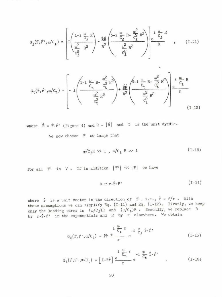
where = •--' (Figure 4) and R I and I is the unit dyadic.
We now choose P so large that
W/CIR >> 1 , w/Ct R >> 1 (1-13)
for all V' in V . If in addition 1i•'j << «i we have
_A ^ r. ( -14)
where 2- is a unit vector in the direction of : , i.e., r - f/r . With
these assumptions we can simplify Eq. (I-li) and Eq. (1-12). Firstly, we keep
only the leading terms in (w/C,)R and (w/Ct)R . Secondly, we replace R
by r-f--' in the exponentials and R by r elsewhere. We obtain
• -i r.'(
AAi e rG1(P,", w/C C) = r e (1-15)
r
i W--r w •Ct -i rt r'
Gt(•,',w/Ct) = [I2--] e r e (I-16)
20

Point ofObservation
Figure 4 - Vector Arxre.ent
21

Now using Eqs. (I-15i and (1-16) in Eq. (I-10) we can find G and
using G in Eq. (1-9) with `q given by Eq. (1-8) we can find i1(f,w) . Then
from Eq. (1-6) we can get q(-,t) . The result of this straightforward but
tedious procedure is
S-f sin JWl W2 A--kl+) ."r (wl-w2 -91 dv
4nC2Po r L C ct
4TTC r 2 f *jC -:ý2 ((C"~-'
4TC2 ~f sin~(L L Pltr (wl-(2)( - t)} dV (1-17')
The first and second terms in Eq. (1-17) are longitudinal waves with the
summed frequency Wl+u 2 and the difference frequency wl-w2 , respectively.
The third and fourth terms are transverse waves with the summed and difference
frequencies, respectively.
The terms in rnc _-guments of the sine function involving ( -t)
do not vary during the P' integration. Now look at the first term in
Eq. (1-17). As we integrate over !' the integrand oscillates with frequency
determined by the coefficient of r' , i.e., --' 2 in this case.CY
In general, the result of this integration will depend on just how the waves
fit into the region V . As we increase V the value of the integral will
oscillate between fixed limits, unless we can find a direction rs for which
l+2 rs-kl-k2 = 0 (1-18)
C 2
22
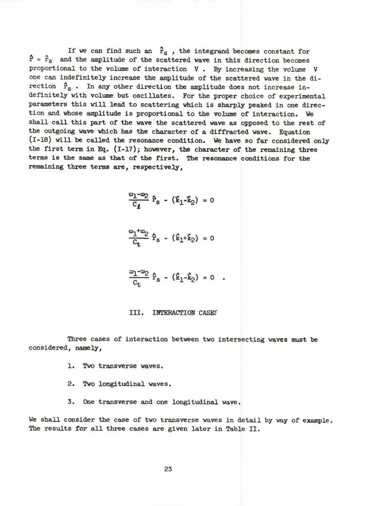
If we can find such an rs , the integrand becomes constant for= rs and the amplitude of the scattered wave in this direction becomes
proportional to the volume of interaction V . By increasing the volume Vone can indefinitely increase the amplitude of the scattered wave in the di-rection % . In any other direction the amplitude does not increase in-definitely with volume but oscillates. For the proper choice of experimentalparameters this will lead to scattering which is sharply peaked in one direc-tion and whose amplitude is proportional to the volume of interaction. Weshall call this part of the wave the scattered wave as opposed to the rest ofthe outgoing wave which has the character of a diffracted wave. Equation(1-18) will be called the resonance condition. We have so far considered onlythe first term in Eq. (1-17); however, the character of the remaining threeterms is the same as that of the first. The resonance conditions for theremaining three terms are, respectively,
Ct - (014) = 0
-t+,2s - (k14•2) = 0
•s- (•l-t2)=-o .Ct
III. INTERACTION CASEF
Three cases of interaction between two intersecting waves must beconsidered, namely,
1. Two transverse waves.
2. Two longitudinal waves.
3. One transverse and one longitudinal wave.
We shall consider the case of two transverse waves in detail by way of example.The results for all three cases are given later in Table II.
23

For the case of two transverse waves we have
-A - h .. Wi vA.kl = 1 -k 2 =0 and -k, kett
We want first to see if the resonant condition Eq. (1-18) can be catisfied.We must have
2
or
2 1ýw ~2 W a2- 2wjw-2-- +- COS 9
ýý--A) C2 C2 C2
where cp is the angle bet-ween k1 and k2 . The above leads to
CO P= C? + 1 -l')(-Dl +u2
In order that this equation be satisfied we must have the right side less thanone and greater than minus one. This leads to the condition that
l-Ct/Cj WI I+Ct/Cf1+ct/cz 2 <- c lt/C-
For any wl/w2 , in this range we can choose the angle y between the primarywave vectors k, and k2 so that we get a scattered wave (appearing in thedirection of l1+2) . If one examines the resonance conditions for the lastthree terms in Eq. (1-17) it turns out that ncne of them can be satisfied forthis particular choice of primary waves. For the scattered wave then, we havefrom Eq. (1-17) only the longitudinal wave
24
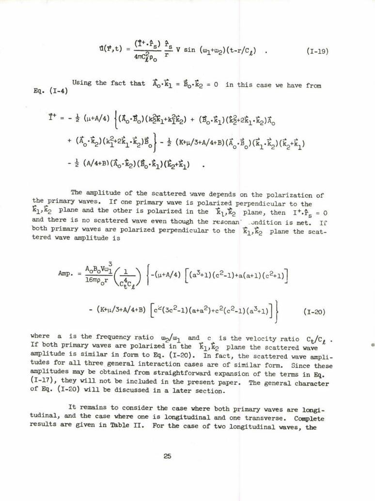
41C+po r V sin (wl+w2 )(t-r/Cd) (1-19)
Using the fact that Ao-kl = Bo.k2 = 0 in this case we have fromEq. (1-4)
I" = -½ (,i+A/4) t¢ .1 )(k -,,-k 2) -,-
+ 1 1k+2l ) o l0 0 12 21
- (A/4+B)(A k')(1'•1Z)(2+tl)
The amplitude of the scattered wave depends on the polarization ofthe primary waves. If one primary wave is polarized perpendicular to therlj, 2 plane and the other is polarized in the •I,2 plane, then I+-.% = 0and there is no scattered wave even though the resonan -ndition is met. Il"both primary waves are polarized perpendicular to the it1,t 2 plane the scat-tered wave amplitude is
Amp. = A°B°V5 t( { - (+A/4) [(a3+l)(c2.1)+a(a+l)(c2+l)1
- (K+tL/3+A/4+B) [c L(3c2_1)(a+a2)+c2(c2_l) (a3-I-)1 (1-20)
where a is the frequency ratio u2/wI and c is the velocity ratio Ct/C'eIf both primary waves are polarized in the 1Kl,'2 plane the scattered waveamplitude is similar in form to Eq. (1-20). In fact, the scattered wave ampli-tudes for all three general interaction cases are of similar form. Since theseamplitudes may be obtained from straightforward expansion of the terms in Eq.(1-17), they will not be included in the present paper. The general characterof Eq. (1-20) will be discussed in a later section.
It remains to consider the case where both primary waves are longi-tudinal, and the case where one is longitudinal and one transverse. Completeresults are given in Table II. For the case of two longitudinal waves, the
25
I Vu
V v v cIU
+ A+ 0 0 wi4>1*
cmw
N + +HCiH '
OJ+ + cc
4-)
F -4 0 c
, 0
4)- 4-) -1 w P4
9l 9o 94 w 0Cl *,- r4
J) 0 I Ad4-)
P4,
Hd v- 00 0HH- 0 0 '.
Id 4\i- 4, rdI343 ý4- fx : :
H H- +- 4- -) 1E*,oU H,- .1iv 4 A 00 r
0) c 4 34-
1o .0 HI-I~,1 4,) HHHd US
+d DI 4- -
cc ~ Cc > 4 4).o D4 0)r. 0: H0 0 (n 4,SnP4H H
co + 4- 4-3 (0 -1) O 43 +3 4-l
H 4,i> 4-)r ,IC4, taQ) bocodoul ,i4-4
H -i, 0 4 ký $ ~4 rikS 0S 0l4 00 0- 4, 0
0l 4) rci) rWCd -4 W-H *.- V 9H$- -H4,C
0U 0dU 0d) 'S, 444ca.U 0,O
4-'4-4- -U)426f

resonant condition can be satisfied for the fourth term of Eq. (1-17) only.For the remaining case the resonant conditions can be satisfied for the first,second, and fourth terms. In this latter case of interaction between a longi-tudinal and a transverse primary wave, the amplitude of the longitudinal scat-tered waves vanish when to is polarized perpendicular to the plane ofkl,k2 . The transverse scattered wave has finite amplitude for any polariza-tion of Bo "
The appearance, in Table II, of scattered waves with the differencefrequency wl-u2 requires some comment. Treatment of the interaction problemhas been on a strictly classical basis in this paper. The classical treatmentis an approximation to the correct Quantum Mechanical treatment. A macroscopicplane elastic wave consists of the presence of a very large number of phononsof a particular (long) wavelength in the crystal. With this in mind one cando the following calculations:
1. Write down the phonon Hamiltonian for the crystal including thefirst term giving phonon-phonon interaction.
2. Assume that at t = 0 , there are a large number of phonons withwave vectors S, and k2 and energies fiuI , tw2 .
3. Assume that first order time dependent perturbation theory isvalid and compute the state of the system at some time tI later than t = 0
If one does this calculation the following points appear. Due tothe structure of the phonon-phonon interaction there is conservation of thephonon wave vector (no Umklapp processes are possible if the initial wave-lengths are very long). That is, a phonon of wave vector kI and one ofwave vector k2 can produce, in interaction, only phonons of wave vector
t3 = 1+ý2 - The second point is that if tI is not chosen too small, theperturbation theory gives only energy conserving transitions, that is, wemust also have llu 3 = t 2 +hwl . These conditions on the wave vector andenergy taken together are equivalent to the resonance condition from Eq.(1-18). A troublesome point is, however, that this calculation seems to indi-cate that a scattered wave with the difference of the primary frequencies can-not arise, in contrast to the classical calculation which permits a scatteredwave of either the sum or difference frequencies. It is therefore not clearto us whether or not the difference frequency waves will actually be producedin an experiment. Since the validity of the assumptions made in both calcula-tions is somewhat of an open question, it is difficult to make a more definitestatement at the present time.
27
IV. BEAM WIDTH OF SCATTERED WAVE
The scattered wave given oy Eq. (1-17) appears in the form of a
conical beam with vertex at the interaction zone and maximum intensity alongA
the direction of the vector rs . In experiments aimed at detecting the scat-
tered wave it would be advantageous to minimize the spread of this beam. The
parameters which determine the angular width of the beam may be identified as
follows.
Consider the first term in the right-hand side of Eq. (1-17). The
amplitude of the integral is equal to the volume of interaction V whenA Ar = r • We seek here the vector for which the amplitude first becomes
zero or a minimum) as r moves away from . This occurs when one full
cycle of the wave is fitted into V , or in other words, when the coefficient
of V' is approximately equal 2TT/I , A being a length characterizing the
volume of interaction. It follows that the angular width of the beam is
proportional to Xs/2 where Xs is the wavelength of the scattered wave.
Thus the scattered beam will be narrow when Xs << i . For the case we are
considering Xs is inversely proportional to wl+w2 so the width of the
scattered beam may be made small by using large primary frequencies and/or
a large interaction volumen.
When the other terms in Eq. (1-17) are considered, the same propor-
tionality to Xs/1 is obtained. However, for the second and fourth terms,
Xs is inversely proportional to wl-w2 which suggests that in general a
scattered wave with the difference frequency will be more spread out.
V. NUMERICAL EXAMPLE
We use a numerical example to illustrate the previous results.
Choosing polystyrene for the elastic medium we have_/
X = 2.89 x 10¹⁰ dynes/cm2
S= 1.38 x 10¹⁰ dynes/cm2
K = 3.81 x 10¹⁰ dynes/cm2
28
A* = -1.00 x 10¹¹ dynes/cm2
B = -8.3 x 10¹⁰ dynes/cm2
C = -1.06 x 10¹¹ dynes/cm2
Po = 1.056 gm/cm3
Taking again the case of two transverse primary waves we find that resonancecan be obtained for
0.338 < a < 2.955
Since the two primary waves are the same type, we may without loss of gener-ality choose wl > w2 which restricts a to the range
0.338 <a _ 1
The smallest angle p between the primary waves for which a scattered (reso-nant) wave is obtained is 120.8 degrees corresponding to a = 1 .. As a de-creases, 4p approaches 180 degrees.
If both primary waves are po.arized perpendicular to the 11,;plane, the scattered wave amplitude Eq. (1-20) is largest for a = I . Wethen obtain
Amp. (max.) = 10.32 x 10-B AoBoVw3/r cm.
(when Ao, Bo, and r are in centimeters, V in cubic centimeters and ciin radians/sec). As a decreases, the amplitude passes through a minimum ata f 0.583 and we find that
Amp.(min.) = 7.45 x 10⁻¹⁸ AoBoVwi/r cm.
* The correlation between the elastic constants I , m , and n given inRef. 3 and A , B , and C used here is: A = n , B - m-½n , C = u-m+½n.
29
Clearly, the amplitude is more sensitive to the primary -ave frequencies
characterized by wl , than to the frequency ratio.
Let us further evaluate the interaction in polystyrene of two 10-
megacycle waves with a volume of intersection equal to 1 cm. If the displace-
ment amplitude of the interacting waves is approximately 10-10 cm. and we let
r = 10 cm., then the displacement amplitude of the scattered wave is calculated
to be approximately 10-1 5 cm. By maintaining the same volume, frequency, and
observation distance, we see that the amplitude of the scattered wave varies
as the product of the primary wave amplitudes. Thus, the difference between
the amplitudes of the primary waves and the scattered wave decreases as Ao
and Bo get larger. If we use the unreasonably large value of 10-6 cm. for
Ao and Bo (this corresponds to a strain amplitude of about lO-3 in the above
example), then we find that the amplitudes of the intersecting and scattered
waves are of the same order of magnitude.
VI. CONCLUSIONS
Two intersecting plane elastic waves produce a scattered wave when
the resonant condition (Eq. (1-18)) is satisfied. The resonant condition is
a function of the ratio of the primary frequencies but is independent of the
absolute frequencies. The scattered wave appears in the approximate form of
a conical beam emanating from the volume of interaction and has maximum in-
tensity along the direction ?s defined by the resonant condition. The width
of the beam is proportional to Xs/1 where XS is the wavelength of the
scattered wave and A is a length characterizing the volume of interaction
V . The maximum intensity of the scattered wave is greatest for high primary
frequencies, large primary wave amplitudes, and large interaction volume.
In an experiment aimed at detecting the scattered wave, the distance
L from the interaction zone to the point of observation should be large com-
pared with I . Therefore, optimum experimental conditions art.
L >> t >> Xs
30
BIBLIOGRApHy
1. F. R. Rollins, "Ultrasonic Methods for Nondestructive Measurement ofResidual Stress," WADD TR 61-42, Part I (1961).
2. F. D. Murnaghan, "Finite Deformations of an Elastic Solid" (John Wiley &Sons, Inc., New York, 1951).
3. D. S. Hughes and J. L. Kelly, Phys. Rev., 92, 1145 (1953).
4. A. SeeCer and 0. Buck, Z. Naturforschung, 15a, 1056 (1960).5. T. Bateman, W. P. Mason, and H. J. McSkimen, J.A.P. 32, 928 (1961).
6. A. Granato and K. nLcke, J.A.P., 27, 583 (1956).
7. A. Granato and K. Lficke, J.A.P., 27, 589 (1956).
8. P. C. Waterman and L. J. Teutonico, J.A.P., 28, 266 (1957).
9. .T. G. Walker, H. J. Williams, and R. M. Bozorth, Rev. of ScientificInstrumentr-, 20, 947 (1949).
10. Z. A. Goldberg, Soviet Physics Acoustics, 6, 306 (1961).
U. P. M. Morse and H. Fesnback, '!Methods of Theoretical Physics," Part II,Chap. 13 (McGraw-Hill Book Co., Inc. 1953).
31
o0 ID 4. .4
'.0 N' I' .400. -
t' ~ 7 MI~5
a~0 4
P1 -4~ 4 1.
44 000 .04.5 0. 02 *4..0 * 0 4) 04 00 ** 54 0 $4 '
.40.4 00 Q) 0 0 40'4~ 4 .;. 0'4 00 4
92 a~ 4- 0,4 Ow 4) 0 l4.45400( o 00 0 0~ W- M M 00V44-
'40 914 44W -'' ýb 4 4.9
'-4~~~~~ 0 0004 204 0-40 0 0 .44 ~ 0 0 N 4- P0 39 0 02544. OM.4.. 0>
k o .0 .0 k 0 .0 0 0 Z4
0. 54 4 .0 )
*0 0 P.0 0 040 0 v 5 0 0 '*4 4.
#, 40 04 . 13 , ;00 4 OE. 45.0 4) 4)0.0-0--4 ' 0 AI-C o 0 a40 .4 4 - C-D- w00%-.
UU4.~~~O~~> -4 00 14.4' 0 0 0 ~ O 4o4.54 f4 4.0'40D4.00+f00 -k
Q4~ ~ 4 . ~ ~44 00c 041 -P' 4 ~ ) 0 0
z 0'-0 ) A 0 >'4 1 10 4
* 4' .I 0 02 IQ0 c 40* C- 13 4- 0 Uý$ a-
a a COO0 .- - C'
ý4 . 0 4 04 . . 4 . .. 0 o 4 - 0 0 " 90 40J 4& 4 4 0- ilc 40 0 0 0 0 0 4
0 44 akV 0 A -',40 a o 17 OR i .0 . 0 4a . 2 0 -0 0 140.4 .t) 40 >* 400 t 3 Iý 4 -$
4 4 - CU 0 0 -.4 0 0 0 0 '0 0 .- 0a
. P. .4. a .
0. .O. 0.-I . 0 0 0.4 00o 41 -4O~ 4-.44 U0 0. 0 0 0.4.0 0~ a 4.54oo4. '44. 00 4.
'0 .00 00.40 . 00
cn 00 54IQ .C-4.4 n5 0 5 '. 0 4
4S .0 N, 054 .44- r4
-0 .l000
,4 054 4.a GO 0l 410 .0 .0 .
4I '4 .4 . 4 0 00on4'
to40 .m E 04 0 C-
>,.4. 00 13 0 04'0 0-.- 44 4. 4) 4014 4. 0 4 4. .0 40 .0-400 93 0 -4.42 0 0 to 00 0 0 40 4 .0 -,I
14 04. -0~. a4 0. 4.54 * 00v40.404. 0. 000 V '-4 O4 030.40 U- 00 .4 - k04. 0~~~ '4 k0'0 1405 0~0 .
44 4 C m *0050.' 4'08W
4. 0 '4) . 4 4 4 0q 4. V~0 '..40. 04.- %r( ) $ 4.000.4t ,40I.r.00534.4
le A04 4)0 C 3 9 - . go .0 _ F0.W 4 -4.00 0 0 000 l00.

- 44-
'0 14 00 I aD m4 - -4
'.0 '.0 .0 +(0 ca -4. In) 0
n 0 0 0~ 0l -.4 0
@4) 4) .4 H4k40 P4 @4p H
.4 0 CJ. O O
(0*04 004 0 .444- t-)01'
'044. 4)4 A 4W00 0$
1- -P Id -4 +-I> - ý 1 .,
0 0 0~ ý4- L .() , w4F3 -P 01 ( )040+
4) to0 -'.4 4 : $0
0 k 9-4 4wka 9 4 "t 1 11 014 +-4~ . 0 co0.4) 4)0'a 04)0 a 0 4..').. V
14M$44 4) 4)0 0i.4 0.447---4 44 H- x 0 0 'A )0 cl
0 0
au -4 4)4)0.4 ) 4) - $4 . .0p .440)0' 4.k E4) 0)p)44 c ý ý. 0 4w000w ;
0 4) 0O~ CO0.43)00 0 44.0' P : 00
40 01- k04 )0 ) . +- 0 44) 000-4 0 do40 0 c 1 ( 0 40 § V)
4) a4)4.'Q ý 44) 4 +4 4) (1)i'-4 0
4- .0 0 3 U 4 .0 4- )1 -4) 1044-
+- k4. k. ' 40 + +4 4) .0+4 0)cm4 o4 0 ) )0 04-'04 O.4 ý )4 C - 4 )ý
co. 1 4 40 - 4- ( 0 $.'. 04) l4 Z~- m 4 4 + + . 13.) -4 4 - ) 1 4> D 400 0 .4 .00 Q 0 ,4-4 +4Q H 0 a4 .. 4-.a 00.0 OD4) -P0~40Q$
00~~~4 93~~ 44-0-'4 0l +'.4)4 . -400
144)0 .4 - .4 ) I-4$ 0I + 04* $ .' 0 100 ' 0o 44 $. 0 a %.0-4 ),1 '00 7- 0 0 4)W 03$4- '1 04+44'
.0*.+7 .4ý 0. k)4 13 00+4 024)4
+5 0- +4a k0 .. 4$4 4)4) l.40 V 0-4 0.44) 0 (L) )4- 0 O A 4 0 R 0.4 0 40 0 +- $ 3 4 H 4 4 - '0 40 V 4 )4 -k
Z$W14 . 4) $.0 k-44-. 0 40+4 k 0J0 -1 W -440 Q .4 0+P.)4)4)4- .4 ~ .4-C0 U4k 44)44 400
A4 4A 00 +,4T0 ID0 is 0-4
'.0 -.0 .0. _4
o'k 0, 0 ' CV i 4, 0
kUO .4 4))
'+034 - 40
- - $ -
S.-4 1 4 -4 k 4P4C E M
k ;1 '0 0 ) D7 0 k) a) 0 $
14 '0 co + >1 04 0 $4)04+-. .. 2A4 54) 0. 'U 4) ' 00.ca0 +40 -
* 0+0 4-4) .0+)- 04)
I~+ ca 00 C ()40~0 40Hm'0 0 4)) 4)00. 0t5 a'44 .44) C? 00r. .4w-go0 $4D) 0 - +4)4
4-0 0 .4 4-. 40 (D' - 4 4) 4 0 0 r4 OH D )
04 k ~ 4) -.44))4+4H4) 0 0 0- 0-. 04 41COC4-. ~ ~ 1 0+ ) 1-4 4) +4.04 0))) 4-$
0 J4-.0 004+ 4.4~)) 4) 0-$04)~~ *O) 4 O)0 4) 0.+ 4)+13 4ý 0ý
-40 '1- .4) '0Q I-+ .0 Q))54 4 Q))4-9) 01- Z4 4)4 U) k)40 > 0 54 U 04~ 0 kH0 V +
C- 0v4 4ý0 0-4 0 .4.0 41) 00 "00 4 > 0 00+4 .4 4 Q 0m .4
100 . -.4 W '0Pr 4 4 Q 0 0 0 k .000 0 4) .00 4 ,0.4:R
93 0 50504 0ý4 W 0) W.)O 0 4) 0 +410 14 1-
cc ', 3 . a z44 -j 0.0. ) H
4- 04) ,4 00a-4 ýH4 4) 0.00 0 04 _ -. 40 ~~1-4 * >14++44. 04)H,)00.04
0 4 +4 144 1 . 4-' ( )4)
00~q -0+7 g H 0- -44)44)'0.
4- A4 0. 0 .404- 045044'0 0
-a C3 0 4)0.D 0.4 4a .01: 00+ '