nondestructive testing of wire hoisting rope by magnetic …together withareportof...
TRANSCRIPT

DEPARTMENT OF COMMERCEBUREAU OF STANDARDSGeorge K. Burgess, Director
TECHNOLOGIC PAPERS OF THE BUREAU OF STANDARDS, No. 315
[Part of Vol. 20]
NONDESTRUCTIVE TESTING OFWIRE HOISTING ROPE BYMAGNETIC ANALYSIS
BY
R. L. SANFORD, Physicist
Bureau of Standards
April 16, 1926
PRICE, 10 CENTS$1.25 PER VOLUME ON SUBSCRIPTION
Sold only by the Superintendent of Documents, Government Printing Office
Washington, D. C.
WASHINGTONGOVERNMENT PRINTING OFFICE
1926

T 315
NONDESTRUCTIVE TESTING OF WIRE HOISTINGROPE BY MAGNETIC ANALYSIS
By R. L. Sanford
ABSTRACT
In an endeavor to meet the great need for a reliable nondestructive methodfor the testing of wire hoisting rope the Bureau of Standards has conducted aninvestigation of the possibilities of magnetic analysis for this purpose. Theinvestigation has been of a fundamental nature, consisting in a study of the mag-netic properties of steel wire of the kind used in the manufacture of wire rope
and the effect on them of deterioration due to various causes. The effects of
stress, wear, and fatigue were studied. While it is evident that there is a very
close connection between the magnetic and mechanical properties of steel, the
relationships are so complex that much more study will be needed before the
results of magnetic tests can be interpreted with a sufficient degree of certainty
to warrant their use as a practical method for the routine inspection of wire rope.
CONTENTSPage
I. Introduction 497
II. Magnetic analysis 498
III. Magnetic exploration 499
IV. Effect of stress 504
V. Effect of wear 510
VI. Effect of repeated stress 514
VII. Other effects 515
VIII. Summary and conclusions 516
I. INTRODUCTION
It is difficult to tell just when a hoisting rope should be removedfrom service and a new one substituted. While it is desirable to
utilize the full life of the rope, it is dangerous and oftentimes very
expensive to leave a rope in place too long. The resulting damagemay amount to many times the cost of putting in a new rope before
the end of the useful life of the old one has been reached, to say nothing
of the life hazard. By the present methods of visual inspection it is
impossible to ascertain the conditions of a rope with certainty.
The inspector must depend upon his judgment, based upon accu-
mulated experience, together with certain arbitrary rules with regard
to the number and distribution of broken wires. Under these
497

498 Technologic Payers of the Bureau of Standards [Vol.20
conditions it is not at all surprising that occasionally ropes fail soon
after being pronounced safe by a competent inspector. This is not
necessarily due to any fault on the part of the inspector, but rather
to the lack of an adequate testing method by means of which the true
condition of the rope can be determined.
In an endeavor to meet the need for such a testing method, the
Bureau of Standards, during the two-year period beginning July 1,
1923, carried on an investigation on nondestructive methods for test-
ing wire hoisting rope. This work was supported by a special appro-
priation granted by Congress at the urgent request of important
interests concerned with the use of wire rope for hoisting. Contact
with these interests was maintained through an advisory committee
to the bureau composed of representatives of various national tech-
nical societies and experts in the manufacture, use, and inspection of
wire rope. Before starting the work a meeting of this committee
was held, at which the problem was discussed and various physical
properties which might be made the basis of a nondestructive test
were considered. It was agreed that magnetic analysis appeared to
offer the greatest promise and that this should be given first atten-
tion. Accordingly, the investigation has been devoted mainly to a
study of magnetic analysis with reference to its use as a nonde-
structive method for testing wire rope. In view of the fact that the
appropriation was not continued beyond the two-year period, it
seems desirable to present at this time a brief discussion of magnetic
analysis with special reference to the testing of wire rope, together
with a report of the results obtained during the progress of the
investigation.
II. MAGNETIC ANALYSIS
By magnetic analysis is meant testing by magnetic methods and
using the results thus obtained as criteria of the mechanical quality
or condition of the material so tested. Obviously, this method can
only be applied to ferromagnetic materials, and thus far attention
has been given primarily to steel and steel products.
The expectation that use can be made of the results of magnetic
tests is based upon the fact that any treatment which alters the
mechanical properties of a piece of steel to a measurable extent at
the same time changes its magnetic properties. Although no excep-
tion to this general principle has been found, the magnetic properties
of iron and steel are so sensitive to many influences which do not
affect the other physical properties to a corresponding degree that
the estimation of mechanical quality in terms of the results of mag-netic tests has proven to be very difficult. This condition has thus
far placed a serious limitation on the industrial application of mag-netic analysis as a method of routine inspection.

San ford] Testing Wire Rope by Magnetic Analysis 499
During the past few years a number of investigations have been
carried out on various phases of magnetic analysis, and several
methods of magnetic testing have been developed. 1 In the investi-
gation here reported main attention has been given to the methodsof magnetic exploration and the interpretation of the test results.
III. MAGNETIC EXPLORATION
By magnetic exploration is meant the determination of the degree
of magnetic uniformity along the length of a specimen. Since any
irregularity in the mechanical properties of a specimen is accompanied
by a corresponding irregularity in its magnetic properties, this
. -XL
Fig. 1.-
—
Diagrammatic representation of magnetic exploration apparatus
method at once suggests itself as a means for detecting flaws andimperfections.
The apparatus by which magnetic explorations are carried out
consists essentially of (1) a magnetizing soleniod surrounding the
specimen, (2) a test coil connected to an indicating instrument, and
(3) means for producing relative motion between the coils and the
specimen. In most cases the apparatus is arranged to record the
deflections of the indicating instrument photographically. Figure
1 is a diagrammatic representation of the apparatus.
The magnetizing coil used in the present investigation consisted
of 3,007 turns of No. 17 silk-enamel-covered copper wire wound ona fiber form approximately 20 cm (8 inches) long and 3.8 cm (1^inches) inside diameter. The magnetizing field at the middle of the
1 Sanford, Trans. Amer. Soc. for Steel Treating, 5, p. 577; 1924.

500 Technologic Papers of the Bureau of Standards [ Vol. .
coil was approximately 191 times the current in amperes. There wasalso an outer auxiliary winding of 1,189 turns.
Several test-coil systems were used during the course of the investi-
gation. These coils were wound on interchangeable fiber forms
which could be mounted within the magnetizing solenoid. The test
coils used were either single, double, or triple. The electromotive
force induced in a single coil depends upon the rate of change in the
magnetic flux in the specimen which is linked with the test coil. Thedisadvantage of this type of test coil is that changes of flux, due to
fluctuations in the magnetizing current, give indications which can
not be distinguished from those caused by irregularities in the material
itself.
In order to overcome this difficulty, the test .coil may be in two
parts, each of the same number of turns, and located at equal distances
from the middle of the magnetizing coil. The two parts are woundin opposite directions so that any electromotive forces induced in
one part, due to fluctuation in the magnetizing current, are neutralized
by equal and opposite electromotive forces induced in the other part.
When the variation in flux linkage is caused by irregularities in the
material, however, the resulting electromotive forces induced in the
two parts of the coil do not occur at the same time and deflections are
produced in the indicating instrument first in one direction and then
in the other. The triple coil consists of three parts, one located at
the middle and the others at equal distances either side of it. Themiddle part has twice the number of turns that there are on each of
the end parts. The windings are so arranged that the effect of the
middle part is opposed to that of the two end parts, which are both
wound in the same direction. The object of the three-part coil is
to neutralize, in so far as possible, the effect of the decrease in flux
due to the self-demagnetizing effect as the end of the specimen is
approached. With the triple coil, the electromotive forces due to
an irregularity in the specimen give three deflections, one in one
direction and two in the other. With the two and three part coils,
the magnitude of the deflection due to an irregularity in the material
depends not only upon the magnitude of the irregularity, but also
upon its extent and upon the spacing of the coils. For this reason
calibration is not possible with the multiple coils and the results can
not be expressed on a quantitative basis. Although all three types
of test coil were used in the course of the investigation, the majority
of the tests were made with a single coil, because the results were less
complicated and could be expressed whenever desired on a quantita-
tive basis. Compensation for slight fluctuations in magnetizing
current was made by a duplicate magnetizing solenoid and test coil
connected in series with the main coils and in which was inserted a
sample of material similar to that under test. This method of com-

inford] Testing Wire Rope by Magnetic Analysis 501
pensation was found to be effective for the slight current fluctuations
occurring during the tests. The apparatus is shown in Figure 2.
The magnetizing solenoid and test coil were mounted on a carriage
which was moved along on a horizontal track by means of an electric
motor. The wire specimens were suspended horizontally over the
track, and means were provided for varying and measuring the tension
in the wire. While this method of producing relative motion of
the specimen and coils has been found the most convenient in the
laboratory, in the field the coils would be stationary with the rope
running through them.
Fig. 2.
—
Magnetic exploration apparatus
The character of the record obtained depends not only upon the
type of test coil used, but also upon the indicating instrument. Areflecting galvanometer of the moving-coil type is generally used. If
the instrument has a short period and is critically damped, the instru-
ment behaves as a voltmeter, and the deflection at any instant is pro-
portional to the rate of change of flux finked with the test coil. This
rate depends not only upon the local variations in the magnetic
permeability or cross section of the specimen, but also upon the speed
with which the coil is traveling. If the galvanometer is heavily over-
damped so that the principal control is electromagnetic, then the
instrument behaves as a fluxmeter, and the deflection at any instant
is proportional to the total change in flux linkage since the start.
The indication is then practically independent of speed. The degree
to which this condition is realized depends upon the ratio betweenthe electromagnetic control and the torsional control of the suspen-
sion. The heavily overdamped galvanometer has been found mostsatisfactory for magnetic exploration.

502 Technologic Papers of the Bureau of Standards [Vol.
In Figure 3 is shown the recorder, together with the apparatus for
electrical control and calibration. The photographic record is madeon a strip of bromide paper by means of a spot of light reflected uponit from the instrument mirror. A roll of paper is carried in the top
of the magazine and is carried along by rollers driven by an electric
motor at a speed proportional to that of the magnetizing coil along
the length of the specimen. The paper runs into a detachable light-
tight compartment at the bottom, and, when a record has been
made, the paper can be cut off and taken to the dark room to be
developed. Contacts are provided on the apparatus so that an
auxiliary lamp is flashed within the camera at each foot of travel of
the coils. This produces lines on the record by means of which
Fig. 3.
—
Recorder and control apparatus for magnetic exploration
irregularities can be located. Calibration is made by means of a
variable mutual inductance whose secondary is in the test-coil
circuit. If the specimen is magnetically uniform along its length,
the spot of light remains stationary as the coils are moved along, and
the resulting record is a straight line. Departures from a straight
line indicate nonuniformities in the specimen.
In Figure 4 are shown typical records made with the magnetic
exploration apparatus. These records are illustrative of the diffi-
culty encountered in the interpretation of the results of magnetic
exploration. No. 1 is the record obtained for a sample of stream
line wire used in airplane construction. Although variations in

Sanford] Testing Wire Rope by Magnetic Analysis 503
magnetic permeability of considerable magnitude are indicated, this
wire showed no signs of weakness in actual service, and no flaw or
imperfection was revealed by any other physical test.
Record No. 2 shows at A the effect on another sample, otherwise
comparatively uniform magnetically along its length, of bending the
wire at right angles and straightening again. It is seen that this
really serious defect causes a magnetic variation no greater in mag-
nitude than those found in the wire of record No. 1. These two
\^/\4/\A'VV /vVin. (D
Fig. 4.
—
Typical magnetic exploration records
records were made on samples of the same dimensions using the
apparatus at the same sensitivity. This lack of proportionality
between the magnetic indication and the degree of the mechanical
defect is one of the greatest obstacles to be overcome in the inter-
pretation of the records for practical purposes.
Nos. 3 and 4 are records for the same wire before and after intro-
ducing artificial flaws at B, C, and D. At B a notch was filed in the
wire about one-third of the way through. At C the wire was bent
and straightened, while at D the wire was heated with a burning
83333°—26f 2

504 Technologic Papers of the Bureau of Standards [voi.20
match. Note that the most serious defect, that at B, gives a mag-netic indication which might very well have been disregarded if thedefect had not been known to be there.
In view of the difficulties just indicated, which are typical of the
results of previous investigations, and of the fact that wire rope is in
itself a rather complicated structure, the investigation has been of a
fundamental nature, consisting in a study of the magnetic properties
of hard-drawn steel wires of which rope is made and the effect uponthem of various influences known to cause deterioration in wire ropein service.
The material used in the investigation was furnished by the
American Steel & Wire Co., and consisted of four grades of patented
steel wire known to the trade as " crucible cast steel," " extra strong
crucible cast steel," "plow steel," and " monitor plow steel." Thewires were 0.1 inch in diameter and had tensile strengths ranging from190,000 to 250,000 lbs./in. 2
.
The influences which have so far been made the subjects of study
were stress, wear, and fatigue. In view of the fact that underservice conditions a hoisting rope is always under stress and that the
stress is continually varying while the rope is being used, this element
was considered first.
IV. EFFECT OF STRESS
Although many investigations have been made on the effect of
mechanical stress on the magnetic properties of steel and its nature is
well known, it is doubtful if the importance of this factor in the field
of magnetic analysis has heretofore been fully realized. The results
of the present work show very clearly that this element may have a
very great influence on the results of investigations on the correlation
between the magnetic and mechanical properties of steel.
In order to obtain data on the effect of stress on the magnetic
properties of steel wire of the type used in wire rope, measurements
were made on samples of wire held under various degrees of tension
in a testing machine. The machine used was a Scott horizontal
testing machine of 2,000 pounds capacity having a long frame.
The magnetic tests were made by the ballistic method using a
straight solenoid and a special test coil. The apparatus is shown in
Figure 5. The solenoid was approximately 50 cm (19 J^ inches)
long, wound with No. 17 silk-enamel-covered copper wire on a fiber
form. The magnetizing force at the middle of the coil was approxi-
mately 100 times the current in amperes, and as the coil could carry
10 amperes for short periods without overheating it was possible to
use magnetizing forces as great as 1,000 gilberts per centimeter. Asthe ratio of the length of the specimen to its diameter was well over
200, the self-demagnetizing effect of the ends could safely be neglected.

Sanford] Testing Wire Rope by Magnetic Analysis 505
When measurements are to be made with intense fields, the correc-
tion due to the flux in the space between the specimen and the test
coil becomes very large. In order to avoid the necessity of applying
this large correction, a special type of test coil which has been found
useful in other work was employed for some of the measurements.
In other cases, test coils of 100 turns each were wound directly on
the specimen.
The special test coil consists of two parts—coaxial and coextensive
longitudinally but of different diameter—so adjusted that their area
turns are equal. If these two parts are connected in series opposition
to a ballistic galvanometer, and are placed in a uniform magnetic
field, there will be no deflection of the galvanometer when the direc-
tion of the field is reversed. On the other hand, if there is a specimen
Apparatus for determining the effect of stress
in the coil and the field is reversed, the deflection of the galvanometer
is proportional to the difference in number of turns of the two parts
and the ferric induction (B-H) in the specimen. This is easy to see
from the following equations.
Let A 1 and A 2 , and N± and N2 be the area and number of turns of
the outer and inner coils, respectively, and a the area of the specimen.
H is the magnetizing force and B the flux density in the specimen.
The flux turns (4>N) linked with the two coils are
{4>N) t= Nt B a+ Nt H {Ax -a)
(<t>N) 2= N2 B a+N2 H (A2 -a)
Since the coils are connected in opposition, the flux turns indicated
by the ballistic galvanometer upon reversal will be
(4>N) = (4>N) X- (4>N) 2 = (Nt-Nj) Ba + HiN, A,- N,a- N2 A 2 + N2 a)

506
Since
Technologic Papers of the Bureau of Standards [Voi.20
(<1>N) = (Nt-NJ Ba- (Nt-m Ha= a(Nl-N2 ) (B-H)
The galvanometer is calibrated by means of a standard mutual
inductance whose secondary is in the test-coil circuit and its sensi-
tivity is adjusted by resistances so that 1 cm deflection corresponds
to the reversal of a flux density Z?= 1,000 gausses. The control
apparatus and ballistic galvanometer are shown in Figure 6. Table
1 gives a typical set of test results for one grade of wire.
Fig. 6.
—
Control apparatus and ballistic galvanometer for magnetic induction
measurements
Table 1.
—
Values of magnetic induction (B) for various degrees of stress forcrucible-cast-steel wire
HTensile stress in pounds per square inch
25,500 51,000 76,500 102,000 127,500
5 3701,1202,5005,600
8,10010, 00012, 40014, 050
16, 52017, 60018, 64019, 200
4601,4304,3008,650
10, 82012, 15014, 00015, 150
16, 62017, 30018, 25018, 850
4801,5005,3009,600
11, 80012, 97014, 40015, 150
16, 20016, 90017, 78018, 400
5001,6004,8509,300
11, 55012, 70014, 05014, 750
15, 70016, 37017, 28017, 940
4701,5003,6007,500
9,85011, 40013, 17014, 000
15, 15015, 88016, 80017, 500
49010 1,50015 3,60020 5,700
25 9,10030 10,60040 12, 400
13, 320
14,60015, 35016,350
50
75100150200 17, 030

Sanford] Testing Wire Rope by Magnetic Analysis 507
In Figure 7 are shown graphically the results for no load and for a
load giving a stress of 51,000 lbs/in. 2. The magnetic induction (B)
is increased by tension for the lower values of magnetizing force (H),
but the curves cross and for higher values of magnetizing force the
magnetic induction is reduced by tension. With these data before
us it is easy to see how the effects of stress may interfere with the
proper estimation of mechanical quality in terms of magnetic prop-
erties. We can now explain the small apparent effect of the notch
filed at B in record No. 4 of Figure 4. The normal effect of the
reduction in area would be an apparent decrease in the magnetic
permeability. Actually, however, on account of the higher stress,
Steel Rope Wire
.
Ultimate Strenjtk
Woooo Ibslj^z.
Effect of Tension.
/So Htfajnet/z/'nj Force - Gilberts per cm.
Fig. 7.
—
Effect of stress on magnetic induction
the permeability of the remaining material is higher and the two
effects about neutralize. The irregularities in record No. 3 of
Figure 4 can also be explained as the result of variations in stress
conditions along the length of the sample. It is very evident that,
before the records of magnetic exploration can be interpreted with
confidence, some way must be found of eliminating from the records
the effects of stress or, failing this, of identifying and evaluating them.
In Figures 8 and 9 the data of Table 1 are plotted to show the
change in induction due to tension. In Figure 8 the change is
plotted against magnetizing force for two values of stress, one below
the elastic limit and the other above it. It will be noted that the
maximum effect occurs at about the same magnetizing force in both
cases, but that the reversal of sign does not occur at the same value

508 Technologic Papers of the Bureau of Standards \ Vol. so
of magnetizing force. In Figure 9 the change in induction for the
three different values of magnetizing force is plotted against the
tension. It will be noted that the effect is large for all values of
tension at a magnetizing force of 20 gilberts per centimeter, but
ABHooo
3ooo
Zooo
tooo
-looo _~^£IOOO Ids/ x
-Zooo
5 /<
IZ7SOO lbs/;„z
-3000 >o
AJagnettzinq Force, - Gilberts per cm.
Fig. 8.
—
Showing the effect of tensile stress on magnetic induction
AB is the change of induction at a given magnetizing force
that if a magnetizing force as high as 75 gilberts per centimeter is
used the effect is practically negligible for loads up to 50,000 lbs. /in.2
or more. If this is the case, there should be little irregularity in an
exploration record if a magnetizing force as great as 75 gilberts per
o
s
<u
ABVooo -
"^\H^203000 -
ZOOO - /
Q
-^-^^H=50
'lOOO^^^-^75 ^\\
zooo - ^^^^•JOOO
Sti 'ess in /bs. J»er />t.
SOOOQ looooo
Fig. 9.
—
Showing the relation between stress and the change in magnetic induction
AB for three values of magnetizing force
centimeter is used. This was tried and the results are shown in
Figure 10. The wire was the same one as used for records Nos. 3
and 4 in Figure 4. The upper record was made with a magnetizing
force of about 20 gilberts per centimeter and the lower one was made

Sanford] Testing Wire Rope by Magnetic Analysis 509
with about 100 gilberts per centimeter. In the lower record, the
amplitude of the deflections not due to flaws is greatly reduced but
the effect of the flaws is still definite and distinct. It appears, there-
fore, that the effect of variations in the stress distribution which mayarise from variable conditions during the process of manufacture, and
which do not constitute defects from the practical point of view, maybe eliminated by the use of a sufficiently high value of magnetizing
force in making magnetic-exploration records. It is probably safe to
assume also that effects which are evident at low magnetizing forces
but which disappear at high magnetizing forces are due to variations
in stress distribution. It would not be desirable to eliminate the
#/-»
Fig. 10.
—
Elimination of stress effects by the use of higher magnetizing force
effect of stresses beyond the elastic limit, as stresses of such a magni-
tude constitute a source of danger. It can be seen from the curves
of Figure 9, however, that the change in induction for stresses beyondabout 75,000 lbs. /in.
2 are not negligible for high values of magnetizing
force and would, therefore, appear in the records, taken at high values.
The observations were extended to higher values of magnetizing
force for the purpose of studying the effects of stress in the light of
the reluctivity relationship. This empirical relationship, whichholds for pure homogeneous materials, states that the metallic reluc-
tivity, p= p_ tj , is a linear function of the magnetizing force for
magnetizing forces above a certain minimum value. That is
p = a+(3H

510 Technologic Payers of the Bureau of Standards [Volzo
where a and /3 are constants characteristic of the material. It wasfound that if the material is composed mainly of two longitudinal
components, one of which is in tension and the other in compres-sion, the relationship is no longer linear but hyperbolic. It wasfound possible to resolve the curve into two straight lines, eachrepresenting the magnetic properties of one of the components, andto estimate roughly the relative proportions of material in tension
and in compression. It was concluded that the wire as received hada relatively thin outer layer in a high degree of tension, balanced bythe major portion of the cross section which was in a state of com-pression of much less intensity. This inhomogeneity as regards
condition of stress results in a loss in apparent strength, becausethe whole of the wire never becomes simultaneously effective in
carrying the load. At the elastic limit about half of the material is
still in compression and the rest is beginning to fail.
The results of this part of the investigation were reported in
more detail in a previous paper. 2
From the foregoing it can easily be seen that the effect of mechan-ical stress upon the magnetic properties of steel, which at first wasconsidered as a minor phase of the problem, is of far-reaching im-
portance not only in the present case, but also in the general field of
magnetic analysis. Indeed, it does not seen unreasonable to attrib-
ute a large part of the difficulty encountered in the attempt to
establish definite relationships between magnetic and mechanical
properties to this factor. For many times it has been found pos-
sible to differentiate magnetically between two samples of steel whosemechanical properties appeared to be alike. Such cases might easily
be accounted for by differences in stress conditions not sufficiently
great to modify the mechanical properties to an appreciable extent,
but having a relatively large effect on the magnetic properties.
V. EFFECT OF WEAR
The most obvious result of service in a hoisting rope is wear.
This may occur on the outside of the rope where it is visible, or it
may take place on the inside where it can not be seen. In either
case, it removes material and weakens the rope. Wear does not
take place uniformly along the length of an individual wire but is
concentrated at points where it comes in contact with other objects.
We have already seen in Figure 4 that the magnetic effect of a reduc-
tion in section may not be proportional to the amount of material
removed. It is also conceivable that the removal of material from
the outside of a wire may so modify the stress distribution within
the wire as to change its mechanical effectiveness. In order to
2 Sanford, B. S. Sci. Paper No. 496: 1924.

Sanford] Testing Wire Rope by Magnetic Analysis 511

512 Technologic Papers of the Bureau- of Standards [Vol.
study the phenomena associated with wear under controlled condi-
tions, a machine was constructed by means of which the cross-sec-
tional area of a wire could be uniformly reduced by rubbing against
a steel wheel along a sufficient length to permit of making magneticmeasurements. The circular section of the wire is maintained byrotating it about its axis during the wearing process. The machineis shown in Figure 11. The details of this machine and of the experi-
ments on wear have been described previously, 3 but for the sake of
6
/SOOO
7
/oooo
SOOO
*\&
-
e/S s 7 ^^^L U Q H
()** ^
. <
soo
400
JOO
zoo
/oo
o
-/oo
-ZOO
Fig. 12.
—
Effect of a 17 per cent reduction of area by
wear on the magnetic properties of steel wire
AB is the change in induction at a given magnetizing force
completeness the salient features will be given here. Samples of wire
after having been tested magnetically were worn down in the machine.
At intervals the samples were removed and magnetic tests were
made. The nature of the change in magnetic properties is shown
in Figure 12, AB being the change in induction. The change is
similar in kind, but very much less in magnitude than that resulting
from the application of a tensile force. It was found that the maxi-
mum change occurred at the same value of magnetizing force (H=20)
3 Sanford, Cheney, and Barry, B. S. Sci. Paper No. 516; 1925.

Sanford] Testing Wire Rope by Magnetic Analysis 513
as for tension. The relation between this change in magnetic induc-tion for #=20, and the per cent reduction in area by wear, is shownin Figure 13.
600
400
200
/*f
I
/
/r
!
JO 40 SO20 30
%fted in AreaFig. 13.
—
Relation between per cent reduction in area bywear and change in magnetic induction for H=20
AB is the change in induction
The effect of reduction in area by wear on the tensile strength wasalso determined approximately by breaking in the testing machinea series of samples which had been worn down by varying amounts.The results are shown in Figure 14 and confirm the expectation that
6 Z20
S 2,°
S3
i 200
<s
C3
o
o o n
OO <b i
o
)
60 70O /O ZO SO 40 SOPer cent reduction in area
Fig. 14.
—
Increase in tensile strength of steel wire resulting
from reduction in area by wear
the redistribution of stress resulting from the removal of some of thematerial might result in an increase in the tensile strength in poundsper square inch, although, of course, the total breaking load wasdecreased.

514 Technologic Papers of the Bureau of Standards Woi.w
With regard to the bearing of this element on the results of mag-netic exploration, it was concluded that ambiguity could be avoided,
as in the case of stress, by making the tests at a sufficiently high
value of magnetizing force.
VI. EFFECT OF REPEATED STRESS
One of the principal causes of deterioration of wire rope in hoisting
service is fatigue due to repeated stress. The repeated stresses result
not only from the direct load and vibration, but also from bending
over sheaves and drums. There is at present no method for detecting
the near approach of failure due to fatigue. It has been said 4 that" a magnetic test may be expected to follow the changes in structure
from the initial perfect condition through the various stages of
fatigue to the final rupture. Such changes would be indicated
magnetically, whether they were due to a gradual return to a crystal-
line equilibrium or to stress effects. " So far as the writer is aware,
however, there is no experimental evidence that this is so. Fromwhat is known of the mechanism of a fatigue failure it would appear
that the volume of material involved in the actual failure is such a
small part of that tested that the magnetic effect would be too small
to detect. On the other hand, the fact that there seems to be a
definite " endurance limit" (stress below which failure will not occur
even though repeated an indefinitely large number of times) charac-
teristic of the material might indicate the possibility of a general
change in structure which could be followed magnetically.
During the present investigation only preliminary experiments
on this point have been carried out. A sample of tool steel of un-
known composition was tested in a rotating beam machine of the
Farmer type. 5. Normal induction measurements were made, be-
fore the fatigue test was started, after 501,300 repetitions of stress
and again after 543,500 repetitions. The maximum fiber stress
was 32,200 lbs. /in.2
. The 501,300 repetitions resulted in a small
increase in permeability in the lower part of the magnetization
curve, but no change beyond about H= 50. The maximum increase
was about 33^ per cent; 42,200 more repetitions produced no further
magnetic change although at this point the material was so near
failure that it broke while the machine was being started the next
time. It is probable that the change observed after the first run
really occurred early in the test and was caused by a redistribution
of stress across the section, and that there was no further progres-
sive change as the test proceeded.
* Burrows, Proc. A. S. T. M., 17, pt. 2, p. 96; 1917.
« Moore and Kommers, Univ. of 111. Engr. Exp. Sta., Bui. No. 124; 1921.
Sanford] Testing Wire Rope oy Magnetic Analysis 515
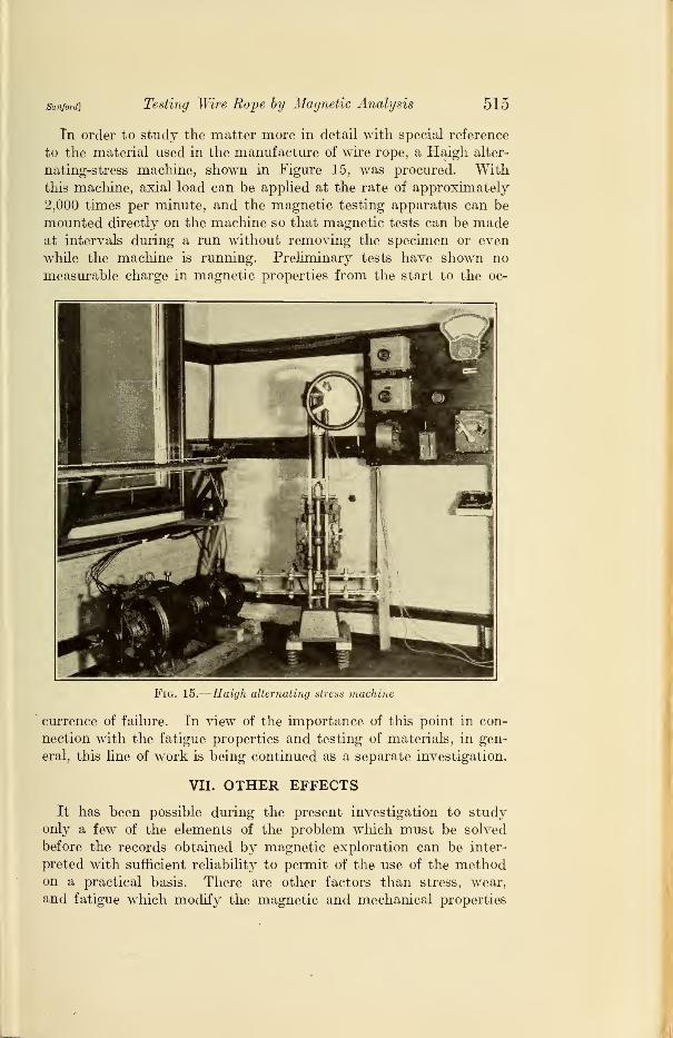
In order to study the matter more in detail with special reference
to the material used in the manufacture of wire rope, a Haigh alter-
nating-stress machine, shown in Figure 15, was procured. Withthis machine, axial load can be applied at the rate of approximately
2,000 times per minute, and the magnetic testing apparatus can be
mounted directly on the machine so that magnetic tests can be madeat intervals during a run without removing the specimen or even
while the machine is running. Preliminary tests have shown no
measurable charge in magnetic properties from the start to the oc-
Fig. 15.
—
Haigh alternating stress machine
currence of failure. In view of the importance of this point in con-
nection with the fatigue properties and testing of materials, in gen-
eral, this line of work is being continued as a separate investigation.
VII. OTHER EFFECTS
It has been possible during the present investigation to studyonly a few of the elements of the problem which must be solved
before the records obtained by magnetic exploration can be inter-
preted with sufficient reliability to permit of the use of the methodon a practical basis. There are other factors than stress, wear,
and fatigue which modify the magnetic and mechanical properties

516 Technologic Papers of the Bureau of Standards [voi.m
of wire rope. Corrosion, cold work, chemical segregation, and a
number of less well understood factors must be investigated.
The material represented by record No. 1, Figure 4, is one example.
It was found in this case that the magnetic variations increased in
magnitude if the magnetizing force was increased. This would ap-
pear to indicate that the irregularities were not due to internal stress.
A definite periodicity in the curve was noted which was finally
found to be associated with the circumference of the 8-inch roll
with which the wire was rolled from the round to the stream-line
section. Two other wires from the same source gave practically
identical curves. In this case variations in magnetic permeability
of considerable magnitude were probably the result of relatively
small variations in the amount of cold work, resulting in permanentdeformation as distinguished from the temporary condition of stress
within the elastic limit, and did not indicate a dangerous condition.
Thus it is seen that the reactions of the magnetic properties of
steel to various influences do not necessarily correspond either in
direction or magnitude with the effect of these influences on the
mechanical properties.
The principal clue to the interpretation of the records lies in the
difference in magnetic effect according to the intensity of the mag-netizing force used. The records of Figure 10 are illustrative of
this point. The effect of the notch at B is small at a low magnetiz-
ing force and more pronounced but in the same direction at the higher
force. The bend at C produced a large effect at the lower force anda smaller one in the same direction for the higher force. The heat-
ing at D caused an increase in permeability at the lower magnetizing
force, but a decrease of about the same magnitude for the higher
magnetizing force. Whether this method of analysis can be devel-
oped to such an extent that the various mechanical effects can be
identified and evaluated in terms of the corresponding magnetic
effects remains to be determined. Until such a basis for the in
terpretation of the results has been established, however, magnetic
exploration would appear to have a very limited value as a practical
method for the inspection of wire hoisting rope or any similar
application.
VIII. SUMMARY AND CONCLUSIONS
Although the present investigation did not result in the develop-
ment of a magnetic device for testing wire hoisting rope, certain
definite results were obtained which have an important bearing
not only on this problem, but also on the general subject of magnetic
analysis.

sanford] Testing Wire Rope by Magnetic Analysis 517
1. Mechanical stress exerts a marked influence upon the magnetic
properties of steel. The effect is most pronounced in the lower part
of the magnetization curve, and to it may be attributed much of
the difficulty heretofore experienced in the attempt to discover
definite relationships between the magnetic and mechanical
properties of steel. The effect of a tensile stress well below the
elastic limit is sufficient to more than double the magnetic per-
meability at a certain value of magnetizing force. Slight variations
in stress conditions along the length of a specimen, therefore, often
give rise to irregularities in the records of magnetic exploration tests
which can not be distinguished from those resulting from flaws.
This stress effect is negligible if higher values of magnetizing force
are used. The proper value for a given material can be ascertained
by trial, but 100 gilberts per centimeter is usually sufficient
to eliminate the ambiguity due to stress effects.
2. The reluctivity relationship is useful for indicating something
of the homogeneity of a specimen across the section. If the
reluctivity plotted against the magnetizing force is a straight line,
then the material is magnetically pure and homogeneous. If the
line is curved, the material is not homogeneous and the degree of
inhomogeneity can be judged by the amount of curvature. If the
only source of inhomogeneity is longitudinal stress, as is the case
of wire used in rope, then it is possible to resolve the curve into the
two straight-fine components and estimate the relative proportions
in tension and compression, respectively.
3. The effect of wear is to reduce the cross-sectional area. Theresult is a modification of the magnetic properties. Also, the break-
ing load is decreased, but not in proportion to the decrease in area,
so that the tensile strength in pounds per square inch is actually
increased. Ambiguity in exploration records due to this cause can
be avoided by using sufficiently high values of magnetizing force.
4. Experimental evidence so far obtained indicates that the
near approach to failure by fatigue is not accompanied bya corresponding change in magnetic properties by which the condition
could be recognized.
5. A single broken wire, either on the outside of a rope or in the
interior, produces a distinct magnetic effect, but, since the magneticeffect of a broken wire generally can not be distinguished from that
due to other causes, the results of a magnetic test are not conclusive
on this point.
6. The effect of cold work has not been studied specifically in the
present investigation, but it is known from the results of other workthat slight variations in the amount of work done on the specimen

518 Technologic Papers of the Bureau of Standards [ Vol. 20
result in relatively large variations in magnetic permeability. Themagnetic effect increases with higher values of magnetizing force.
Ambiguity due to this cause can not, therefore, be removed as in
the case of stress and wear by the use of high magnetizing forces.
7. As a research method for use in the study of the properties of
wire rope and other materials, magnetic analysis has undoubted
value. There are as yet so many sources of uncertainty, however,
that there seems to be no immediate prospect of the development
of a magnetic method for the inspection of wire rope of a sufficient
degree of reliability to warrant its use on a commercial basis.
Washington, January 19, 1926.