nonlinear analysis for behavior of rc horizontally curved
TRANSCRIPT
Jordan Journal of Civil Engineering, Volume 8, No. 4, 2014
- 482 - © 2014 JUST. All Rights Reserved.
Nonlinear Analysis for Behavior of RC Horizontally Curved Ring Beams with
Openings and Strengthened by CFRP Laminates
Ammar Yaser Ali 1) and Sadjad Amir Hemzah 2)
1) Civil Engineering Department, College of Engineering, University of Babylon, Babil, Iraq.E-Mail: [email protected]
2) Civil Engineering Department, College of Engineering, University of Al-Qadisiya,Al-Diwaniya, Iraq. E-Mail: [email protected]
ABSTRACT
This research is devoted to investigate the behavior and performance of reinforced concrete horizontally
curved ring beams with and without openings, unstrengthened and strengthened (externally by CFRP
laminates or internally by steel reinforcement). The experimental work consisted of fabrication and testing of
four reinforced concrete ring beams. The experimental variables considered in the test program included:
presence of opening in the beam, internal strengthening of the beam at the opening by reinforcing steel
(stirrups) and external strengthening (confinement) by CFRP laminates for openings. The beams were tested
under the action of four point loading at the top face of midspans with four supports at the bottom face of the
beams. The ANSYS software was used to analyze by finite element method (FEM) both experimental
specimens and theoretical ones, including the study of size and type of the openings. The results show that the
presence of openings has a great effect on the behavior and ultimate load capacity of ring beams, while the
strengthening of these opening by internal steel reinforcement or external CFRP laminates will increase the
ultimate load capacity and affect post-cracking behavior and mode of failure of these beams. The load
midspan deflection and twisting curves are shown. A comparison between experimental and theoretical
results is also shown. The results computed by FEM analysis and modeling gave good agreement with
experimental results.
KEYWORDS: Ring beams, Opening, CFRP Laminates, Finite element model.
INTRODUCTION
Reinforced concrete horizontally curved ring beams
are used in many fields, such as in the construction of
modern way intersections, circular water tanks, ring
beam carrying domes, circular balconies,… etc. In the
construction of modern buildings, a network of pipes
and ducts is necessary to accommodate essential
services like water supply, sewage, air-conditioning,
electricity, telephone and computer network. Usually,
these pipes and ducts are placed underneath the beam
soffit and, for aesthetic reasons, are covered by a
suspended ceiling, thus creating a dead space. Passing
these ducts through transverse openings in the floor
beams will reduce the dead space and result in a more
compact design.
For small buildings, the saving of dead spaces may
not be significant, but for multistorey buildings, any
saving in storey height multiplied by the number of
stories can represent a substantial saving in total height,
length of air-conditioning and electrical ducts,
plumbing risers, wall and partition surfaces and the
overall load on the foundation (Mansur, 2006).Accepted for Publication on 14/7/2014.
brought to you by COREView metadata, citation and similar papers at core.ac.uk
provided by International Institute for Science, Technology and Education (IISTE): E-Journals
Jordan Journal of Civil Engineering, Volume 8, No. 4, 2014
- 483 -
A horizontally curved ring beam, loaded
transversely to its plane, is subjected to torsion in
addition to bending and shear. Furthermore, it is
obvious that the inclusion of openings in beams alters
the simple beam behavior to a more complex one. Due
to abrupt changes in sectional configuration, opening
corners are subject to high stress concentration that
may lead to unacceptable cracking from aesthetic and
durability viewpoints. The reduced stiffness of the
beam may also give rise to excessive deflection under
service load and result in a considerable redistribution
of internal forces and moments in a continuous beam.
Unless special reinforcement is provided in sufficient
quantity with proper detailing, the strength and
serviceability of such a beam may be seriously affected
(Mansur, 2006). In practice, the most common shapes
of openings are circular and rectangular ones. Circular
openings are required to accommodate service pipes,
such as for plumbing, while rectangular openings
provide the passage for air-conditioning ducts that are
generally rectangular in shape.
With regard to the size of openings, many
researchers use the terms “small” and “large” without
any definition or clear-cut demarcation line. Mansur
and Hasnat (1979) have defined small openings as
those circular, square or nearly square in shape;
whereas, according to Somes and Corley (1974), a
circular opening may be considered as effected when
its diameter exceeds 25% of the depth of the web,
because the introduction of such openings reduces the
strength of the beam. For small openings, two different
failure modes are identified. These types of failure may
be labeled as ''beam-type'' failure and ''frame-type''
failure, respectively, and require separate treatment of
the complete design.
The present research aims to:
1- Investigate experimentally the behavior of
reinforced concrete curved ring beams with and
without openings.
2- Investigate experimentally the behavior of
reinforced concrete curved beams with openings
strengthened by CFRP laminates or internal
reinforcement.
3- Verify the adequacy of the design method
suggested for straight reinforced concrete beams
with openings to utilize for the reinforced concrete
curved beam with openings.
4- Carry out finite element technique to analyze the
nonlinear behavior of reinforced concrete curved
beams with and without openings strengthened by
CFRP laminates up to failure, by using ANSYS
(version 12.1) computer program.
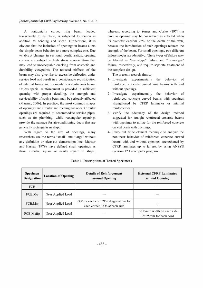
Table 1. Descriptions of Tested Specimens
Specimen
DesignationLocation of Opening
Details of Reinforcement
around Opening
External CFRP Laminates
around Opening
FCB --- --- ---
FCB.Mo Near Applied Load --- ---
FCB.Msr Near Applied Load6Ø 6for each cord,2Ø 6 diagonal bar for
each corner, 2Ø 6 at each side--
FCB.Mcfrp Near Applied Load ---1of 25mm width on each side
3of 25mm for each cord
Nonlinear Analysis for… Ammar Yaser Ali and Sadjad Amir Hemzah
- 484 -
125 mm
250 mm
4Ø 12
Ø 6 @ 4.5°
(b)
(c)
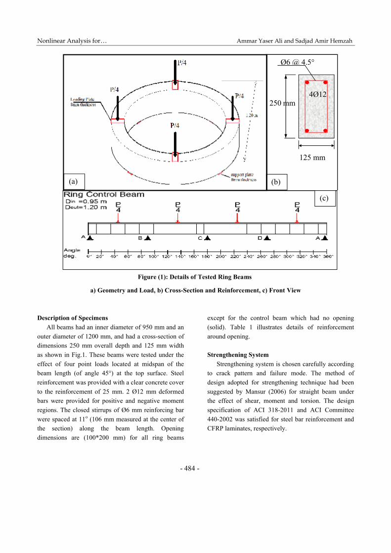
Figure (1): Details of Tested Ring Beams
P/4
P/4
P/4
P/4
(a)
a) Geometry and Load, b) Cross-Section and Reinforcement, c) Front View
Description of Specimens
All beams had an inner diameter of 950 mm and an
outer diameter of 1200 mm, and had a cross-section of
dimensions 250 mm overall depth and 125 mm width
as shown in Fig.1. These beams were tested under the
effect of four point loads located at midspan of the
beam length (of angle 45°) at the top surface. Steel
reinforcement was provided with a clear concrete cover
to the reinforcement of 25 mm. 2 Ø 12 mm deformed
bars were provided for positive and negative moment
regions. The closed stirrups of Ø 6 mm reinforcing bar
were spaced at 11o (106 mm measured at the center of
the section) along the beam length. Opening
dimensions are (100*200 mm) for all ring beams
except for the control beam which had no opening
(solid). Table 1 illustrates details of reinforcement
around opening.
Strengthening System
Strengthening system is chosen carefully according
to crack pattern and failure mode. The method of
design adopted for strengthening technique had been
suggested by Mansur (2006) for straight beam under
the effect of shear, moment and torsion. The design
specification of ACI 318-2011 and ACI Committee
440-2002 was satisfied for steel bar reinforcement and
CFRP laminates, respectively.
Jordan Journal of Civil Engineering, Volume 8, No. 4, 2014
- 485 -
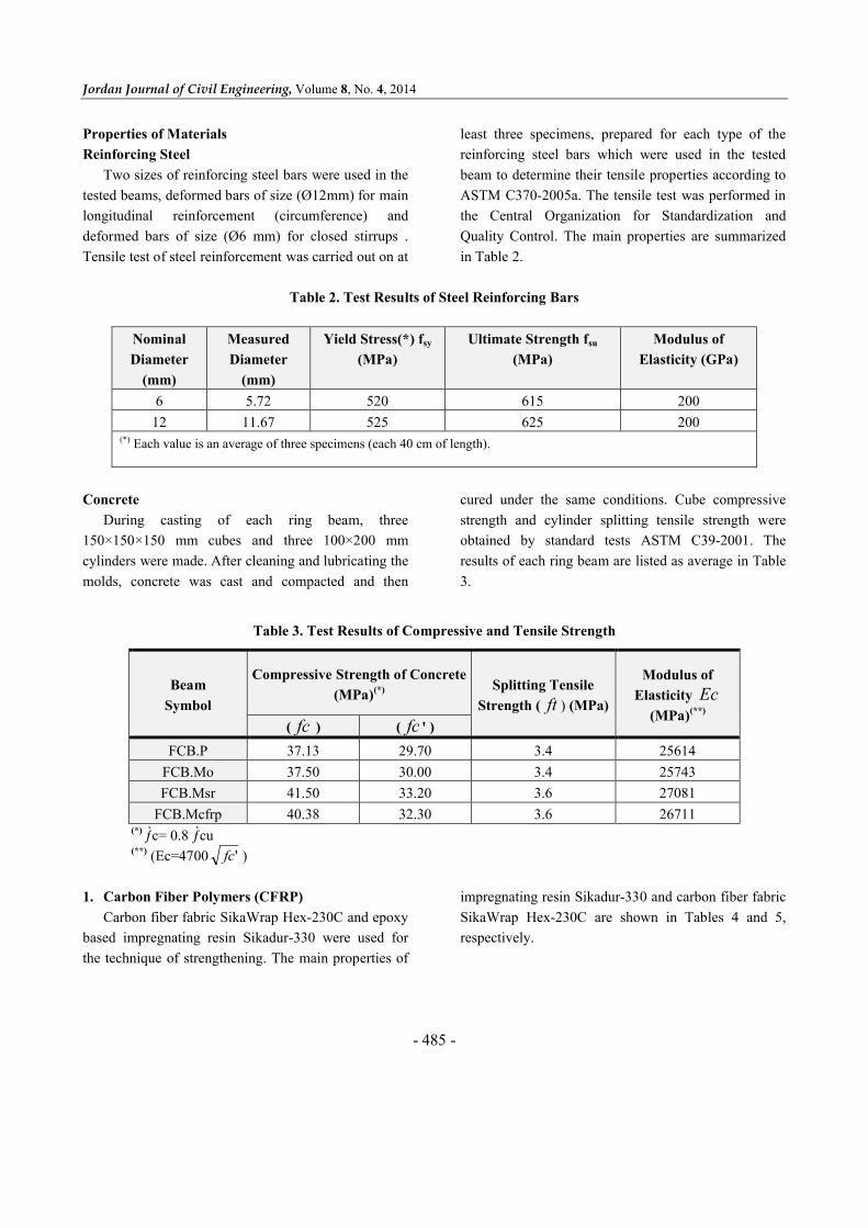
Properties of Materials
Reinforcing Steel
Two sizes of reinforcing steel bars were used in the
tested beams, deformed bars of size (Ø 12mm) for main
longitudinal reinforcement (circumference) and
deformed bars of size (Ø 6 mm) for closed stirrups .
Tensile test of steel reinforcement was carried out on at
least three specimens, prepared for each type of the
reinforcing steel bars which were used in the tested
beam to determine their tensile properties according to
ASTM C370-2005a. The tensile test was performed in
the Central Organization for Standardization and
Quality Control. The main properties are summarized
in Table 2.
Table 2. Test Results of Steel Reinforcing Bars
Nominal
Diameter
(mm)
Measured
Diameter
(mm)
Yield Stress(*) fsy
(MPa)
Ultimate Strength fsu
(MPa)
Modulus of
Elasticity (GPa)
6 5.72 520 615 200
12 11.67 525 625 200(*) Each value is an average of three specimens (each 40 cm of length).
Concrete
During casting of each ring beam, three
150×150×150 mm cubes and three 100×200 mm
cylinders were made. After cleaning and lubricating the
molds, concrete was cast and compacted and then
cured under the same conditions. Cube compressive
strength and cylinder splitting tensile strength were
obtained by standard tests ASTM C39-2001. The
results of each ring beam are listed as average in Table
3.
Table 3. Test Results of Compressive and Tensile Strength
Beam
Symbol
Compressive Strength of Concrete
(MPa)(*) Splitting Tensile
Strength ( ft ) (MPa)
Modulus of
Elasticity Ec(MPa)(**)
( fc ) ( fc ' )
FCB.P 37.13 29.70 3.4 25614
FCB.Mo 37.50 30.00 3.4 25743
FCB.Msr 41.50 33.20 3.6 27081
FCB.Mcfrp 40.38 32.30 3.6 26711(*) ƒ̀c= 0.8 ƒ̀cu(**) (Ec=4700 'fc )
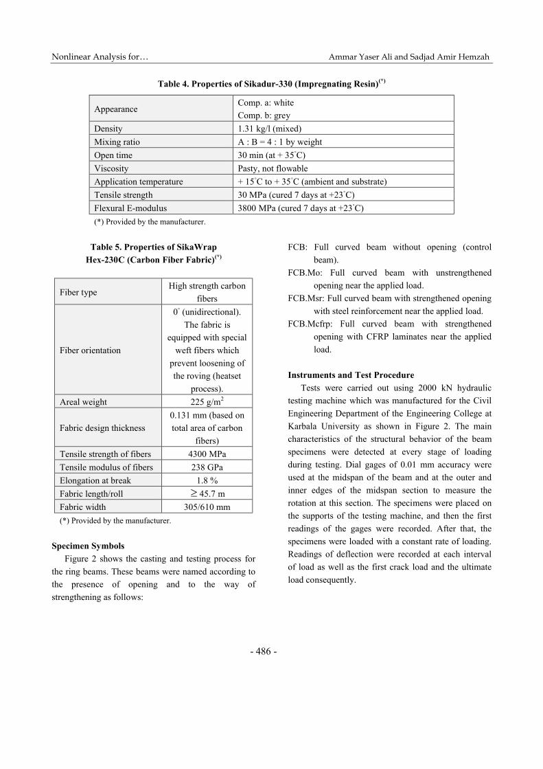
1. Carbon Fiber Polymers (CFRP)
Carbon fiber fabric SikaWrap Hex-230C and epoxy
based impregnating resin Sikadur-330 were used for
the technique of strengthening. The main properties of
impregnating resin Sikadur-330 and carbon fiber fabric
SikaWrap Hex-230C are shown in Tables 4 and 5,
respectively.
Nonlinear Analysis for… Ammar Yaser Ali and Sadjad Amir Hemzah
- 486 -
Table 4. Properties of Sikadur-330 (Impregnating Resin)(*)
AppearanceComp. a: white
Comp. b: grey
Density 1.31 kg/l (mixed)
Mixing ratio A : B = 4 : 1 by weight
Open time 30 min (at + 35◦C)
Viscosity Pasty, not flowable
Application temperature + 15◦C to + 35◦C (ambient and substrate)
Tensile strength 30 MPa (cured 7 days at +23◦C)
Flexural E-modulus 3800 MPa (cured 7 days at +23◦C)
(*) Provided by the manufacturer.
Table 5. Properties of SikaWrap
Hex-230C (Carbon Fiber Fabric)(*)
Fiber typeHigh strength carbon
fibers
Fiber orientation
0◦ (unidirectional).
The fabric is
equipped with special
weft fibers which
prevent loosening of
the roving (heatset
process).
Areal weight 225 g/m2
Fabric design thickness
0.131 mm (based on
total area of carbon
fibers)
Tensile strength of fibers 4300 MPa
Tensile modulus of fibers 238 GPa
Elongation at break 1.8 %
Fabric length/roll 45.7 m
Fabric width 305/610 mm
(*) Provided by the manufacturer.
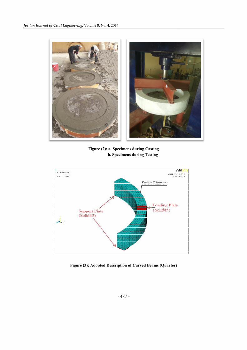
Specimen Symbols
Figure 2 shows the casting and testing process for
the ring beams. These beams were named according to
the presence of opening and to the way of
strengthening as follows:
FCB: Full curved beam without opening (control
beam).
FCB.Mo: Full curved beam with unstrengthened
opening near the applied load.
FCB.Msr: Full curved beam with strengthened opening
with steel reinforcement near the applied load.
FCB.Mcfrp: Full curved beam with strengthened
opening with CFRP laminates near the applied
load.
Instruments and Test Procedure
Tests were carried out using 2000 kN hydraulic
testing machine which was manufactured for the Civil
Engineering Department of the Engineering College at
Karbala University as shown in Figure 2. The main
characteristics of the structural behavior of the beam
specimens were detected at every stage of loading
during testing. Dial gages of 0.01 mm accuracy were
used at the midspan of the beam and at the outer and
inner edges of the midspan section to measure the
rotation at this section. The specimens were placed on
the supports of the testing machine, and then the first
readings of the gages were recorded. After that, the
specimens were loaded with a constant rate of loading.
Readings of deflection were recorded at each interval
of load as well as the first crack load and the ultimate
load consequently.
Jordan Journal of Civil Engineering, Volume
Figure
Figure (3): Adopted
Volume 8, No. 4, 2014
- 487 -
Figure (2): a. Specimens during Casting
b. Specimens during Testing
Figure (3): Adopted Description of Curved Beams (Quarter)

Nonlinear Analysis for… Ammar Yaser Ali and Sadjad Amir Hemzah
- 488 -
Finite Element Modeling
The analysis was carried out using ANSYS 12.1
program. Table 6 shows the elements used in the
analysis.
Table 6. Element Types
Element
No.
Element
TypeRepresentation
1 SOLID65 Concrete
2 LINK8 Longitudinal (circumference) steel
reinforcement mm12 and Radial
reinforcement (stirrups) mm63 SOLID45 Steel plate
4 SHELL41 CFRP
The concrete was modeled with a cubic eight-node
element (SOLID65) with 3 degrees of freedom in each
node, and steel reinforcement was modeled as a one-
dimensional element with two degrees of freedom,
while (SOLID45) element was used for representing
the steel support plate and (SHELL41) was used to
represent the CFRP laminate, see Figure 3. A suitable
mesh size was found to get the analysis results which
give the best solution and the least time.
Finite Element Analysis Results
All tested curved beams have been analyzed by
using ANSYS computer program to determine the
validity of this numerical method for the analysis of
reinforced concrete horizontally curved (ring) beams
with web opening strengthened externally with CFRP
laminates or internally with steel reinforcement. The
overall behavior and specifications for these
strengthened materials have been taken into
consideration in the input data of ANSYS computer
program.
The load-midspan deflection curves, load-midspan
twisting angle curves, cracking and ultimate loads for
all analyzed curved beams have been illustrated
through the following results.
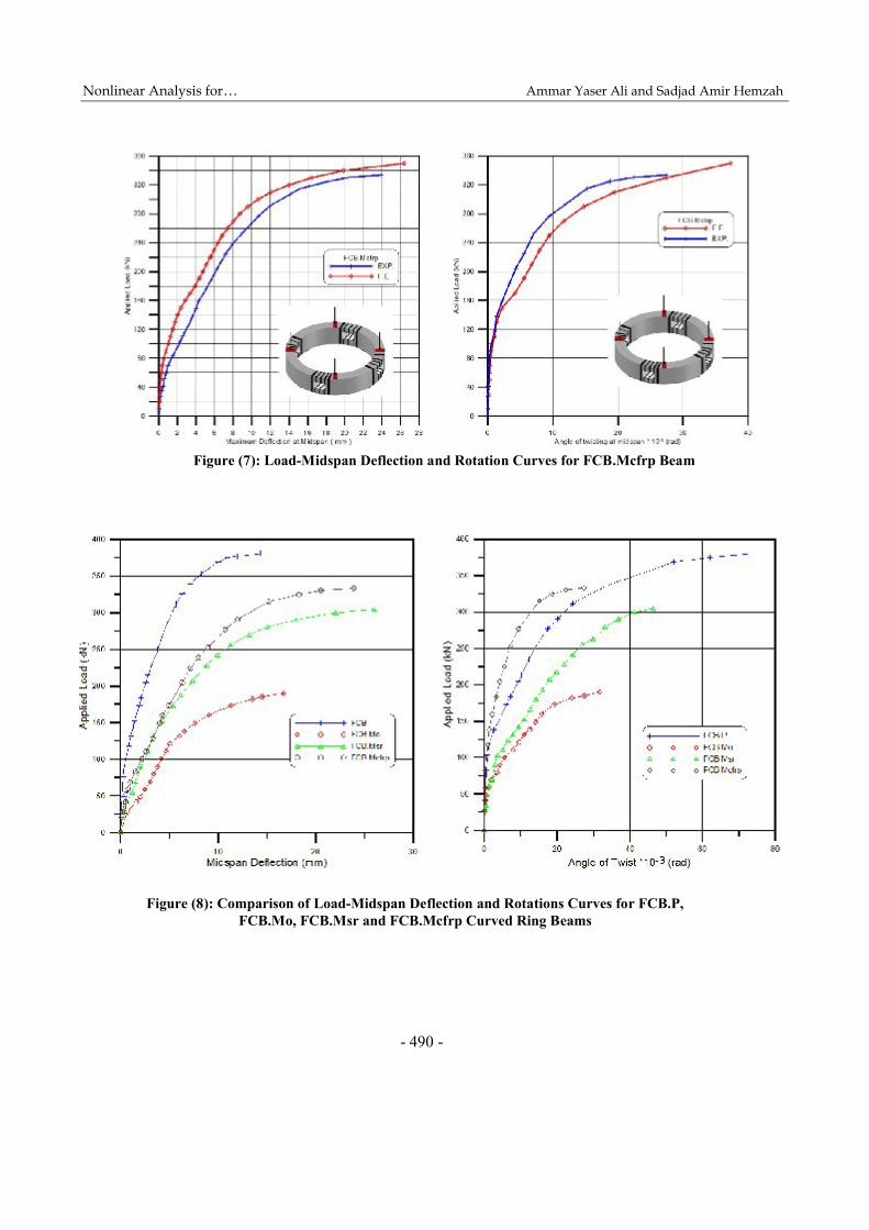
Load – Deformation Curves
Figures 4 to 7 include a comparison between the
load-midspan deflection and the load-midspan twisting
angle curves of the experimental and numerical results.
The variations of mid-span deflection and midspan
twisting angle with the step-by-step loads applied for
all ring beams are all recorded through these curves.
The finite element load-deflection curves for most
beams show a stiffer response than the experimental
results. Micro-cracks produced by drying shrinkage
and handling would reduce the stiffness of the actual
beam, while the F.E. does not include the effect of
micro-cracks. The F.E. analysis assumes that concrete
is a homogenous material, but the truth is that it is a
heterogeneous material. Also, a perfect bond between
the concrete and steel or CFRP laminates is assumed in
the F.E. analysis.
Summary of Test Results for FCB.M Beams
Table 7 shows the cracking load, ultimate load,
percentage of ultimate load with respect to FCB.P
beams. Figure (8) show a comparison of load-midspan
deflection and angle of twist curves for circular curved
beams FCB.P, FCB.Mo, FCB.Msr and FCB.Mcfrp
beams. It can be concluded that the presence of the
openings near the applied load reduces the ultimate
load capacity (compared with control full curved beam)
to the half, also a significant reduction in twisting angle
was noticed because of the ultimate load reduction. On
the other hand, strengthening of the opening by internal
reinforcement or external CFRP laminates increased
ultimate load capacity (compared with FCB.Mo) by
about 60% and 75%, respectively. Also, angle of twist
and deflection were increased with considerable ratio
because of the confinement of the beam at the opening
region which postponed failure at opening for both
types of strengthening. This is because of increasing
post cracking stiffness of the beam at opening which
could be seen clearly in Figure 8.

Jordan Journal of Civil Engineering, Volume 8, No. 4, 2014
- 489 -
Figure (4): Load-Midspan Deflection and Rotation Curves for FCB.P Beam
Figure (5): Load-Midspan Deflection and Rotation Curves for FCB.Mo Beam
Figure (6): Load-Midspan Deflection and Rotation Curves for FCB.Msr Beam
Nonlinear Analysis for… Ammar Yaser Ali and Sadjad Amir Hemzah
- 490 -
Figure (8): Comparison of Load-Midspan Deflection and Rotations Curves for FCB.P, FCB.Mo, FCB.Msr and FCB.Mcfrp Curved Ring Beams
Figure (7): Load-Midspan Deflection and Rotation Curves for FCB.Mcfrp Beam
Jordan Journal of Civil Engineering, Volume 8, No. 4, 2014
- 491 -
Table 7. Summary of Tested Ring Beams
Specimen
Cracking Load, kNUltimate
Load, kN
*Ultimate
Load
Diff. %
Max. θ ×10-3
(rad) at
midspan
Max. Δ at
(mm)
midspan
Failure mode
Corner Flex. Tor.
FCB.P -- 103.8 103.8 380.8 100 74.8 14.34 shear
FCB.Mo 58.8 110.7 95 190 -- 31.7 16.71 Torsional and shear
FCB.Msr 55.4 79.8 89.9 305 60 46.4 26.04 Torsional and shear
FCB.Mcfrp 83 100.4 128 333.5 75 27.4 23.9 Torsional and shear
Difference = (Pu( ) − Pu( . ))/Pu( . )
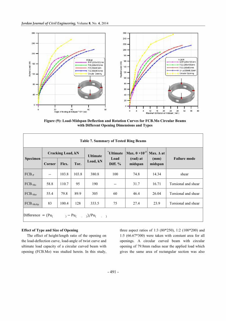
Effect of Type and Size of Opening
The effect of height/length ratio of the opening on
the load-deflection curve, load-angle of twist curve and
ultimate load capacity of a circular curved beam with
opening (FCB.Mo) was studied herein. In this study,
three aspect ratios of 1:3 (80*250), 1:2 (100*200) and
1:5 (66.67*300) were taken with constant area for all
openings. A circular curved beam with circular
opening of 79.8mm radius near the applied load which
gives the same area of rectangular section was also
Figure (9): Load-Midspan Deflection and Rotation Curves for FCB.Mo Circular Beams with Different Opening Dimensions and Types

Nonlinear Analysis for… Ammar Yaser Ali and Sadjad Amir Hemzah
- 492 -
analyzed. Figure 9. shows the numerical results of the
F.E. analysis with experimental results of load-
deflection and load-twisting angle curves for FCB.Mo
curved beams with different opening types and
dimensions. It could be concluded that as the
height/length ratio of the opening decreases, the load
carrying capacity increases. Furthermore, a
considerable increase in load carrying capacity in
beams with circular openings was found. A summary
of the values of collapse loads obtained from F.E.
analysis and experimental test is shown in Table 8.
Table 8. Ultimate Load Capacity for Different Opening Dimensions of FCB.Mo Curved Beams
Beam (FCB.Mo) Opening Length (mm) Opening Height (mm) Ultimate Load(kN)
Rectangular
(Exp.)200 100 195 --
200 100 198 1
250 80 218 1.10
300 66.67 218 1.10
Circular 79.8 79.8 255 1.29
CONCLUSIONS
The following conclusions were drawn from both
experimental and theoretical solutions:
1. Presence of opening in circular ring beams near the
applied load leads to a decrease in ultimate load
capacity by about 50% when compared with the
circular beam without opening (control specimen).
2. For internal strengthening of the opening region,
the ultimate load capacity was enhanced by 60%
and the load-deformation curve was enhanced by
about 75% when compared with unstrengthened
specimens.
3. The use of CFRP laminates as external confinement
in beams with opening near the applied load
increased the ultimate load capacity by about 75%
when compared with unstrengthened specimens.
4. A reliable enhancement appears in post-cracking
behavior of specimens strengthened internally with
steel reinforcement or externally with CFRP
laminates.
5. The use of internal confinement changes the failure
mode from beam type failure to frame type failure,
while the use of CFRP laminates retains the failure
mode to beam type failure.
6. The use of circular opening instead of rectangular
opening with the same area increase the ultimate
load capacity by about 30%.
REFERENCES
ACI Committee 318. (2011). "Building Code
Requirements for Structural Concrete (ACI318M.11)
and Commentary". American Concrete Institute,
Farmington Hills, Michigan, USA, 473 pp.
ACI Committee 440. (2002). "Guide for the Design and
Construction of Externally Bonded FRP Systems for
Strengthening of Concrete Structures". American
Concrete institute, Michigan, USA.
ANSYS Manual. (2009). Version (12.1), USA.

Jordan Journal of Civil Engineering, Volume 8, No. 4, 2014
- 493 -
ASTM Designation C39-01. (2001). "Standard
Specification for Testing Method for Compressive
Strength of Cylindrical Concrete Specimens". Annual
Book of ASTM Standards, American Society for
Testing and Material, Philadelphia, Pennsylvania,
Section 4, (4.02), 20-24.
Mansur, M.A. (2006). ''Design of Reinforced Concrete
Beams with Web Openings". Proceedings of the 6th
Asia-Pacific Structural Engineering and Construction
Conference (APSEC 2006), 5-6 September, Kuala
Lumpur, Malaysia.
Mansur, M.A., and Hasnat, A. (1979). “Concrete Beams
with Small Openings under Torsion”. Journal of the
Structural Division, ASCE, 105 (ST11, Nov.), 2433-
2447.
Somes, N.F., and Corley, W.G. (1974). ''Circular Openings
in Webs of Continuous Beams''. SP-42, American
Concrete Institute, Detroit, MI, 359- 398. (Cited by
Mansur, M.A., 1998).