nonlinear analysis of reinforced concrete structures in ... · procedimentos de projeto, ... ei is...
TRANSCRIPT

Nonlinear analysis of reinforced concrete structures in design procedures: application of lumped dissipation models
Análise não-linear de estruturas de concreto armado em procedimentos de projeto: emprego de modelos de dissipação concentrada
G. M. S. ALVA a
A. L. H. C. EL DEBS b
J. KAMINSKI Jr. c
© 2010 IBRACON
a Universidade Federal de Santa Maria, Departamento de Estruturas e Construção Civil, [email protected], Address: Avenida Roraima 1000 Cidade Universitária CEP: 97105-900, Santa Maria-RS, Brasil;b Universidade de São Paulo – Escola de Engenharia de São Carlos, Departamento de Engenharia de Estruturas, [email protected]. Address: Campus São Carlos Rodovia Washington Luís (SP-310), km 235, CEP 13565-905. São Carlos - SP – Brasil;c Universidade Federal de Santa Maria, Departamento de Estruturas e Construção Civil, [email protected]. Address: Avenida Roraima 1000 Cidade Universitária CEP: 97105-900, Santa Maria-RS, Brasil.
Received: 27 Feb 2009 • Accepted: 04 Jan 2010 • Available Online: 30 Jun 2010
Abstract
resumo
This paper deals with the utilization of lumped dissipation models in the nonlinear analysis of reinforced concrete structures for design procedures, particularly those that deal with material nonlinearity in structural analysis. The main purpose of this paper is to compare the results obtained from the theoretical model with the results obtained from other types of structural analysis, including the simplified proce-dures recommended by NBR 6118 to consider the effects of material nonlinearity. Based on two numerical examples of ultimate limit state verification, some advantages and limitations of the lumped dissipation models in real situations of design are discussed.
Keywords: structural analysis; nonlinear analysis; design of concrete structures; damage.
Este trabalho trata da utilização de modelos de dissipação concentrada na análise não-linear de estruturas de concreto armado em procedimentos de projeto, com ênfase na análise estrutural envolvendo a não-linearidade física. Um dos objetivos principais do trabalho é comparar os resultados fornecidos pelo modelo teórico abordado com os resultados de outros tipos de análise estrutural, incluindo as simplificações preconizadas pela NBR 6118 para a consideração da não-linearidade física. Por meio da análise de dois exemplos numéricos de verificação de Estados Limites Últimos, são apontadas vantagens do modelo de dissipação concentrada em situações reais de projeto.
Palavras-chave: análise estrutural; análise não-linear; projeto de estruturas de concreto, dano.
Volume 3, Number 2 (June, 2010) p. 149 - 178 • ISSN 1983-4195
150 IBRACON Structures and Materials Journal • 2010 • vol. 3 • nº 2
Nonlinear analysis of reinforced concrete structures in design procedures: application of lumped dissipation models
1. Introduction
1.1 Importance of the issue
Reinforced concrete structures exhibit a nonlinear material behav-ior in the service range and especially in the failure range. The main cause of this nonlinearity lies in the fact that the constituent materi-als of these structures do not present an elastic-linear behavior. Material nonlinearity can easily be seen in the uniaxial stress-strain curves of concrete and steel as well as in the moment-curvature diagrams of the sections. In general, cracking and yielding of steel and concrete are the main causes of material non-linearity in rein-forced concrete structures.In the last decade, important and diverse advances have been made in the research of structural non-linear behavior (static and dynamic), giving rise to quite satisfactory mechanical models that more precisely simulate structural behavior. In the domain of tech-nological development, computational advances have contributed significantly to structural engineering as these resources are im-portant elements in the development of numerical simulation tools. Presently, the great capacity of computer processing allows the utilization of constitutive models and complex numerical methods that better reproduce static and dynamic structural behavior. In design, structures, including those of reinforced concrete, are traditionally designed with the results of an elastic-linear analysis. Although simple procedures and models are desirable and impor-tant in a structural design situation, it is crucial that the designer have a critical posture with regard to the use and limitations of an elastic-linear analysis in the dimensioning of structural ele-ments. Theoretical and experimental results demonstrate that the hypothesis of elastic-linear behavior can present results both against and in favor of safety. In other words, it can lead to the construction of structures that are less safe or less economic. In particular, it is important to emphasize the impossibility of an elastic-linear analysis to represent the redistribution of inter-nal force in the structure due to changes in section stiffness. In many cases, a structural analysis with the hypothesis of linear and elastic behavior can underestimate the internal forces in the less stressed sections and overestimate the internal forces in the more stressed sections.In a global structural analysis, in order to avoid the greater com-plexity of an analysis that includes material non-linearity, several studies and codes propose a simplified consideration of material non-linearity through the reduction of the initial stiffness of the sections, generally related to the gross concrete section. Item 15.7.3 of the Brazilian code for concrete structure design, NBR 6118:2003 [1], presents a procedure for the approximate (simpli-fied) consideration of material non-linearity, prescribing reduced flexural stiffness values, based on the type of structural element (beam, column or slab). Although this can lead to acceptable results within a given field of application and from the perspective of global displacement, it should be recognized that the adoption of a single coefficient of reduction of section stiffness for the structural elements, as stipu-lated by NBR 6118, is a very simplified procedure. In terms of internal forces, the differences can be relevant. Moreover, there is a lack of consensus within the specialized literature as to the proper stiffness reduction of elements, shown by the great vari-ability of values proposed, as mentioned by Pinto [2]. In reality,
the coefficients of stiffness reduction of elements in a simplified consideration depend on a series of factors and especially the structure’s geometry, the elements’ rate of reinforcement and the type of load.Codes for concrete structure design, including NBR 6118, allow the utilization of an elastic-linear analysis followed by a correction of the internal forces in order to consider the non-linear behavior of the structural materials. This correction is known as internal force redistribution and it depends on the ductility of structural elements, especially in the more stressed sections. In hyperstatic beams, internal force redistribution is realized through the re-duction of negative moments, utilizing redistribution coefficients, which are limited by norms based on the neutral axis position and the compressive strength class. This reduction in the peaks of the bending moments diagram can allow greater exploitation of the materials, especially of the negative reinforcement in the support sections. However, Carvalho et al. [3] alerted that the redistribu-tion coefficients adopted by structural designers are not founded on technical bases, but rather are often random, adopted auto-matically, with single values for a set of structural elements. It should be underlined that internal force redistribution in rein-forced concrete elements is limited by the plastic rotation capac-ity of the critical sections. In order to dimension redistribution coefficients outside of the limits prescribed by codes, it must be verified that the plastic rotation demand be greater or equal to plastic rotation capacity. This verification avoids situations in which the ultimate load is inferior to the load corresponding to diagrams of internal force modified by linear analysis with mo-ment redistribution. Such situations are known as cases of partial moment redistribution, as highlighted by Lopes et al. [4]. The explicit verification of the plastic rotation capacity can be carried out through a plastic analysis or a non-linear analysis. However, plastic analyses are limited to relatively simple struc-tures, because the determination of collapse mechanisms is un-feasible in hyperstatic systems such as space frames, in the face of the diverse combinations of actions that must be considered. In structures with more complex geometries and those undergoing different combinations of loads, the use of a non-linear analysis to find the plastic rotation capacity is more viable. Despite the advances in nonlinear analysis of structures and the computational resources available, professionals continue to encounter difficulties in the application of more sophisticated mechanical models in structural design. These difficulties are re-lated to the increased amount of time necessary for non-linear analysis, the great number of parameters that may be required by constitutive models or the difficulty to obtain these parameters from characterization tests of the structural materials. It is important that the mechanical models utilized in design be consistent and simple, considering only essential parameters and those that are capable of guaranteeing safety with regards to ulti-mate limit states. Evidently, these models should be validated in comparison with experimental results, especially when the struc-tural behavior involves material non-linearity.
1.2 Justificationfortheutilizationoflumped dissipation models
The model studied in this paper falls within a group of models known as lumped dissipation models, since energy dissipation

151IBRACON Structures and Materials Journal • 2010 • vol. 3 • nº 2
G. M. S. ALVA | A. L. H. C. EL DEBS | J. KAMINSKI Jr.
2. Lumped dissipation models
The first lumped dissipation models were proposed by Giberson [20] and Otani [21] and consisted of elastic-linear beam elements with inelastic rotation springs at the element ends. Improvements of these models were proposed in the studies of Soleimani, Pop-ov and Bertero [22] and Filippou and Issa [23], which took into account the increase of the inelastic zone length. Subsequently, models based on damage mechanics arose. The lumped dissipation model dealt with in this study is derived from the models originally proposed by Flórez-López [24], Cipol-lina and Flórez-López [25], Cipollina, López-Inojosa and Flórez-López [26] and Flórez-López [27]. The models consider energy dissipation in reinforced concrete elements to be due both to concrete damage and to yielding of the tensile longitudinal rein-forcement. As a simplification, it is assumed that this dissipation is found lumped in plastic hinges of null length, preserving the elastic behavior in the remainder of the beam. Therefore, the non-linearity of the structural behavior, due to the energy dis-sipation located in the hinges, is represented by two scalar vari-ables, which are: (i) damage variables at the member ends (di and dj), related to the smeared micro-cracking of the concrete, with values between 0 and 1; and (ii) plastic rotations at the member ends due to permanent strain after steel bar yielding. The stiffness matrix of a plane frame element with six degrees of free-dom (figure 1), considering damage variables at the member ends (di and dj), is presented by Álvares [15], according to Equation (1).
where:
EI is the flexural stiffnessA is the transversal section area of the elementL is the length of the element.
processes (damage and yielding) are considered to be respon-sible for the non-linear response that occurs in previously de-fined zones, which are located at the element ends of a beam finite element. Lumped dissipation models are based on damage mechanics, which has drawn attention for its simulation of the numerical responses of diverse materials, especially concrete, al-lowing the quantification of deterioration processes arising from the formation of cracks in the macroscopic mechanical behav-ior of the material and the structure. In damage mechanics, the constitutive laws are written based on a damage variable, which corresponds to the reduction of stiffness and strength properties of the materials.The pioneer work by Kachanov [5] that introduced the concept of continuum damage proposed a description of the effect of collec-tive degradation through a scalar variable, representing an inher-ently discrete process by a continuum damage variable. The initial interest in this work was related to creep failure in metals under axial tension. Later, models applied to concrete began to gain at-tention, such as those proposed by Mazars [6] and La Borderie, Pijaudier-Cabot and Mazars [7]. In recent years, a good deal of research has been carried out at the São Carlos Engineering School (EESC-USP) dealing with the for-mulation and application of models based on damage mechanics [8-13]. Studies dealing specifically with lumped dissipation models include those by Álvares [14-15], Pituba [16], Alva [17] and Araújo [18].One of the main advantages of the lumped dissipation model con-sidered in this study lies in the simplicity associated with the input parameters required by the constitutive model, which are few and familiar to structural engineers and can be estimated from the usual calculation of the reinforced sections. In addition, the small number of finite element degrees of freedom reduces computational costs, making its application in the analysis of concrete framed structures attractive. The good correlations with a number of experimental results ob-served in diverse research studies provide a good indication of the potential of this theoretical model in applications in design code checking related to the ultimate limit state.
1.3 Objectives of this study
Initially, the main concepts of the lumped dissipation model are briefly presented as are the main parameters required by the con-stitutive model. Subsequently, a comparison is drawn using some experimental results and the numerical response provided by the theoretical model. The studies of Alva [17] and Araújo [18] provide comparisons with experimental results for a number of reinforced concrete structures (beams, frames, beam-column connections and frames with semi-rigid precast connections), validating the ap-plicability of the lumped dissipation model.Finally, some numerical examples of design applications are pre-sented. These examples deal with the dimensioning of continuous beams in a reduced frame model (gravity loads) and the structural analysis of plane frames (gravity and horizontal loads), situations in which the effects of material non-linearity are important. Some data on the potential of this model in design applications were pre-sented by Alva [19]. In this study, the results obtained from non-lin-ear analysis with procedures and other types of structural analysis allowed by NBR 6118 are discussed in greater detail.

152 IBRACON Structures and Materials Journal • 2010 • vol. 3 • nº 2
Nonlinear analysis of reinforced concrete structures in design procedures: application of lumped dissipation models
Figure 2 illustrates, from the moment-rotation curve of a reinforced concrete section, the main input parameters of the constitutive mod-el at hand. In a design situation, these parameters can be obtained from the conventional reinforced concrete theory and with the usual hypotheses of ultimate state limit caused by normal stresses. For the calculation of ultimate plastic rotation, the curves present-ed in item 14.6.5 of NBR 6118 for obtaining the rotation capacity of the plastic hinges can be used as can the simplified expression of Equation (6). However, it is important to note that the plastic rotation capacity of reinforced concrete elements is influenced by a number of factors, including bond properties between steel and concrete, strength and ductility of the steel bars, mechanical properties of concrete under tension and compression, the shear force effect, the cross-section shape and the slenderness and size of the element. The precise calculation of plastic rotation capac-ity is therefore a complex task. Several experimental and theoreti-cal studies related to plastic rotation capacity can be cited, among them those by Dilger [28], Bachmann [29], Langer [30], Hillerborg [31, 32], Kreller [33], Longfei [34] and Sigrist [35].
Dissipation caused by processes of damage evolution and plastic strains obeys the principles of thermodynamics of solids. Details on procedures to identify the laws of evolution of damage and plas-ticity variables can be found in the studies previously mentioned [18, 25 and 26].In order to refine the numerical response of the theoretical model, modifications of the laws of evolution of damage variables were proposed by Alva [17], creating the non-dimensional parameter (γ). This constant depends on the type of structural element and was shown to be strongly influenced by the longitudinal tensile re-inforcement rate in different analysis with experimental results. The limit function proposed by Alva [17] for damage evolution is given by Equation (2):

153IBRACON Structures and Materials Journal • 2010 • vol. 3 • nº 2
G. M. S. ALVA | A. L. H. C. EL DEBS | J. KAMINSKI Jr.
where:G is the thermodynamic moment, given by
2
d1M
S21G
−=
M is the bending moment acting at the member end;
Mr is the cracking moment of the section;
γ is the parameter introduced for the simplified model.
It should be noted that the greater the value of γ, the greater the damage evolution. The value of γ should be chosen so as to more efficiently represent the experimental response observed in the structural element. Thus, the non-dimensional γ is not an undeter-mined parameter. For a structural design situation, it is suggested that the value of γ be chosen based on the longitudinal tensile re-inforcement rate, in accordance with the comparison of numerical and experimental results from item 3 of this study. The limit function that controls the plastic rotation evolution was not modified and is presented by Equation (3).
where:α is a constant of the element that varies between 0 and 1 and is obtained experimentally. For reinforced concrete elements in general, a value of 0.8 is recommended.;θp is the plastic rotation at the hinge;p is the absolute value of the maximum plastic rotation reached by the hinge during the whole loading history. The constants c, My, and q characterize the structural element and are calculated, without great difficulty, through the resolution of the following system of non-linear equations:
Based on the laws of damage and yielding evolution, the expres-sions of increments of the variables of damage and plastic rotation can be deduced:
where
Both yielding evolution laws and damage evolution laws should be applied independently for positive and negative loads at both member ends. It is important to point out that this model was designed for beam el-ements, but it will also be applied to column elements in this study, provided that these are mainly subjected to bending and that nor-mal force is small. In the case of elements subjected to significant normal forces, prior studies are necessary in order to evaluate loss of axial and bending stiffness (based on bending moment–axial force–curvature diagrams, or on the integration of stresses in the concrete and the steel bars over the cross sections, so as to make the employment of the lumped dissipation model more general in concrete structures.
3. Experimental and theoretical results
In order to validate the theoretical model, results obtained from the lumped dissipation model should be compared with experimental results obtained from tests on reinforced concrete structures. Sev-eral comparisons between theoretical and experimental results can be found in the studies of Cipollina and Flórez-López [25], Flórez-López [27] and Picón and Flórez-López [36], which even in-volve the case of cyclic loading. Later, in the doctoral dissertations of Alva [17] and Araújo [18] some improvements were proposed for the original lumped dissipation models which aimed to obtain numerical responses with better reproducibility when compared to experimental results. The model’s limit functions were implemented in a computation-al program developed in FORTRAN language for the non-linear analysis of plane frames, which utilizes an incremental-iterative procedure with either force or displacement control, depending its convenience in the analysis or based on the expected response for the structure. For the numerical solution of the non-linear prob-lem, the Standard Newton-Raphson incremental-iterative proce-dure was utilized, in which the tangent stiffness matrix is updated at each iteration. Two convergence criteria were employed: that

154 IBRACON Structures and Materials Journal • 2010 • vol. 3 • nº 2
Nonlinear analysis of reinforced concrete structures in design procedures: application of lumped dissipation models
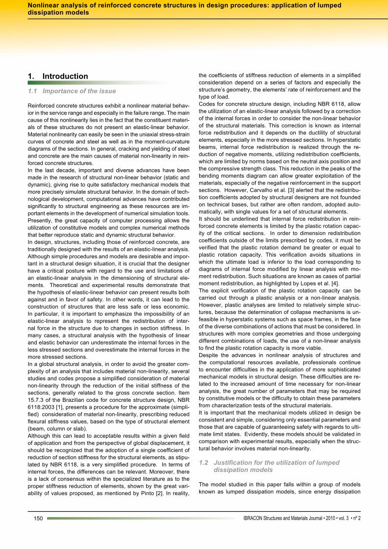
which involves the norm of the residue vector (forces) and that which involves the norm of residual displacements.Figures 3 through 5 present the comparison between numerical results from the lumped dissipation model and experimental re-sults from simple supported reinforced concrete beams tested by Álvares [14]. Beams with three different rates of tensile longitu-dinal reinforcement were tested (beams with little reinforcement, normal reinforcement and great reinforcement) in order to assess the influence of the amount of reinforcement on the response of the theoretical model. As can be seen in figures 3 to 5, the model satisfactorily reproduces the non-linear behavior observed in the force-displacement curve, especially for loads close to the failure of the beam. The numerical model also satisfactorily provides the beam carrying capacity. Figures 3 to 5 and experimental results not presented in this paper
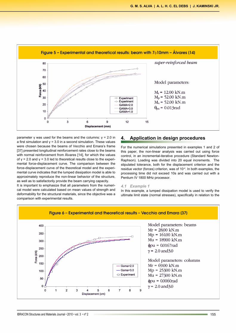
indicate that the value of the non-dimensional γ that best fits the experimental curves increases with the decrease in the quantity of longitudinal reinforcement. In the case of beams, the smaller the quantity of tensile longitudinal reinforcement, the greater the value of the non-dimensional γ coefficient, which is due to the higher level of damage that will occur in reinforced concrete beams.Figure 6 presents the results from the numerical model and the experimental results found in Vecchio and Emara [37] for a rein-forced concrete frame with one-span and two-story height. Load-ing consisted of the application of vertical axial loads of 700 kN to the columns in order to simulate the effect of gravity forces and of a horizontal F force in the direction of the upper beam, measuring the horizontal displacement of the frame. Greater details on the assays can be found in Vecchio and Emara [37].In the numeric simulation, the same value of the non-dimensional
155IBRACON Structures and Materials Journal • 2010 • vol. 3 • nº 2
G. M. S. ALVA | A. L. H. C. EL DEBS | J. KAMINSKI Jr.
parameter γ was used for the beams and the columns: γ = 2.0 in a first simulation and γ = 3.0 in a second simulation. These values were chosen because the beams of Vecchio and Emara’s frame [37] presented longitudinal reinforcement rates close to the beams with normal reinforcement from Álvares [14], for which the values of γ = 2.0 and γ = 3.0 led to theoretical results close to the experi-mental force-displacement curve. The comparison between the force-displacement curve of the theoretical model and the experi-mental curve indicates that the lumped dissipation model is able to approximately reproduce the non-linear behavior of the structure, as well as to satisfactorily provide the beam carrying capacity. It is important to emphasize that all parameters from the numeri-cal model were calculated based on mean values of strength and deformability for the structural materials, since the objective was a comparison with experimental results.
4. Application in design procedures
For the numerical simulations presented in examples 1 and 2 of this paper, the non-linear analysis was carried out using force control, in an incremental-iterative procedure (Standard Newton-Raphson). Loading was divided into 20 equal increments. The stipulated tolerance, both for the displacement criterion and the residue vector (forces) criterion, was of 10-4. In both examples, the processing time did not exceed 10s and was carried out with a Pentium IV 1800 MHz processor.
4.1 Example 1In this example, a lumped dissipation model is used to verify the ultimate limit state (normal stresses), specifically in relation to the

156 IBRACON Structures and Materials Journal • 2010 • vol. 3 • nº 2
Nonlinear analysis of reinforced concrete structures in design procedures: application of lumped dissipation models
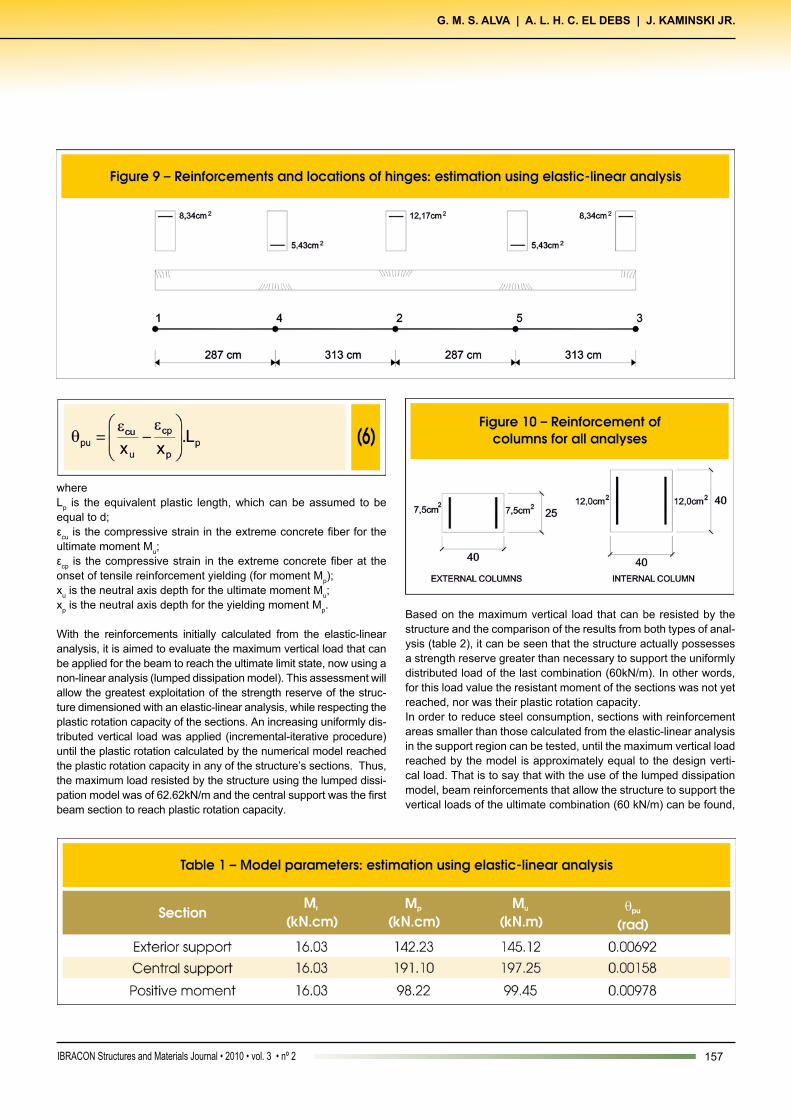
longitudinal reinforcement necessary for bending moments. The example involves a continuous beam subjected to vertical loads and supported by three columns (figures 7 and 8). In this specific case, it is assumed that horizontal loads of wind and geometric imperfections are negligible, which justifies the use of the reduced frame model in figure 7, with a distance between floors of 2.80m. It is assumed that, for the most critical combination of the ultimate limit state, the beam will be subjected to a vertical load of 60 kN/m. The beam possesses a 20cm x 50cm rectangular transversal sec-tion and an effective depth of 46cm. The external columns possess a 20cm x 40cm rectangular section (with bending around the axis of greatest inertia) and the central column possesses a 40cm x 40cm squared rectangular section. The same materials were uti-lized for the beam and the columns: C25 concrete and CA-50 steel for the longitudinal reinforcement.With the bending moments determined from the elastic linear analysis (figure 8), the beam longitudinal reinforcements were de-signed in the negative moment sections (supports) and the positive moment sections. The bending moment diagram from the elastic-linear analysis was also used to determine the position of the mod-el’s hinges (figure 9), which was defined based on the maximum moment sections.In the linear analysis (with or without internal force redistribution), the dimensioning of the reinforcements in the support regions
should respect ductility conditions, which are presented in item 14.6.4.3 of NBR 6118. For concrete with characteristic compres-sive strength lower than 35 MPa, the relation between neutral axis depth and effective depth (x/d) should be lower than 0.5. Verifying the ductility condition in the supports, it can be seen that:
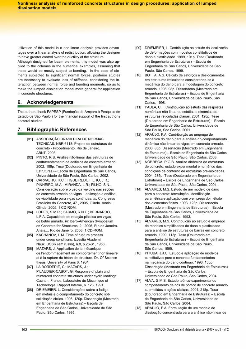
Therefore, the dimensioning obeys ductility conditions. Symmetric reinforcements were adopted for the columns in all of the analysis, as shown in figure 10. With the reinforcements calculated, it is possible to define all the model’s input parameters, which were determined from the con-ventional reinforced concrete theory, including the hypotheses of ultimate limit state for normal stresses, in accordance with NBR 6118. The values for the ultimate limit state were used for the strengths of the concrete and steel materials. Therefore, the input parameters of the numerical model take account of mate-rial partial safety factors for steel and concrete. Table 1 shows the model parameters, obtained from the usual calculation of the reinforced sections. The ultimate plastic rotations of the sections were calculated using a simplified procedure, as recommended by Ibracon [38]:
157IBRACON Structures and Materials Journal • 2010 • vol. 3 • nº 2
G. M. S. ALVA | A. L. H. C. EL DEBS | J. KAMINSKI Jr.
whereLp is the equivalent plastic length, which can be assumed to be equal to d;εcu is the compressive strain in the extreme concrete fiber for the ultimate moment Mu;εcp is the compressive strain in the extreme concrete fiber at the onset of tensile reinforcement yielding (for moment Mp);xu is the neutral axis depth for the ultimate moment Mu;xp is the neutral axis depth for the yielding moment Mp.
With the reinforcements initially calculated from the elastic-linear analysis, it is aimed to evaluate the maximum vertical load that can be applied for the beam to reach the ultimate limit state, now using a non-linear analysis (lumped dissipation model). This assessment will allow the greatest exploitation of the strength reserve of the struc-ture dimensioned with an elastic-linear analysis, while respecting the plastic rotation capacity of the sections. An increasing uniformly dis-tributed vertical load was applied (incremental-iterative procedure) until the plastic rotation calculated by the numerical model reached the plastic rotation capacity in any of the structure’s sections. Thus, the maximum load resisted by the structure using the lumped dissi-pation model was of 62.62kN/m and the central support was the first beam section to reach plastic rotation capacity.
Based on the maximum vertical load that can be resisted by the structure and the comparison of the results from both types of anal-ysis (table 2), it can be seen that the structure actually possesses a strength reserve greater than necessary to support the uniformly distributed load of the last combination (60kN/m). In other words, for this load value the resistant moment of the sections was not yet reached, nor was their plastic rotation capacity. In order to reduce steel consumption, sections with reinforcement areas smaller than those calculated from the elastic-linear analysis in the support region can be tested, until the maximum vertical load reached by the model is approximately equal to the design verti-cal load. That is to say that with the use of the lumped dissipation model, beam reinforcements that allow the structure to support the vertical loads of the ultimate combination (60 kN/m) can be found,

158 IBRACON Structures and Materials Journal • 2010 • vol. 3 • nº 2
Nonlinear analysis of reinforced concrete structures in design procedures: application of lumped dissipation models
while still respecting the plastic rotation capacity of the sections. As an example, the reinforced area of the member end sections was reduced from 8.34 cm2 to 7.10 cm2 and that of the central support section was reduced from 12.17 cm2 to 10.80 cm2, increasing the area of positive reinforcement from 5.43 cm2 to 6.00 cm2 (figure 11) in virtue of the moment redistribution. Table 3 shows the model parameters for the new reinforcement areas. Once again, when an increasing load is applied to the beam in an incremental-iterative procedure through a computational program, a maximum vertical load of 60.36 kN/m is reached (figure 12) and the central support section is the first to reach plastic rotation ca-pacity. Therefore, the reinforcements chosen for the beam will al-low the structure to resist the ultimate limit state design loads and obey ductility conditions. With respect to the elastic-linear analysis, the application of the lumped dissipation model in the beam design (non-linear analysis) resulted in a 15% reduction in the area of negative reinforcement for the end support and of 11% in the nega-tive reinforcement area for the central support. Table 4 presents the results of the analysis of the ultimate combination. One of the advantages of the non-linear analysis using the lumped dissipation model when compared to a linear analysis with redistri-bution is that the reduction of negative moments occurs naturally
due to the loss of stiffness in the sections, measured by damage variables, and due to the plastic rotations calculated by the model.

159IBRACON Structures and Materials Journal • 2010 • vol. 3 • nº 2
G. M. S. ALVA | A. L. H. C. EL DEBS | J. KAMINSKI Jr.
Therefore, the numerical model does not require an arbitrary impo-sition of the redistribution coefficient, avoiding the risk of introduc-ing discrepant or arbitrary moment redistribution. In addition, the numerical model allows the designer to have greater control of the ductility of the structural elements, since the model requires the evaluation of the plastic rotation capacity of the most stressed sec-tions as an input parameter.
4.2 Example 2
This example aims to simulate a typical situation in the design
of multistory buildings, where the consideration of material non-linearity is necessary for the analysis of the global behavior of the building and, in particular, for the evaluation of global sec-ond order effects. The structure in question consists of a plane frame subjected to vertical (permanent and live loads) and hori-zontal loads (wind forces), where the wind was chosen as the main variable action in the load combination analyzed. Although this example deals with a very simple geometric structure (figure 13), the aim here is to provide a quantitative notion of the results supplied by the model for this type of verification and compare those results with those obtained from procedures recommend-

160 IBRACON Structures and Materials Journal • 2010 • vol. 3 • nº 2
Nonlinear analysis of reinforced concrete structures in design procedures: application of lumped dissipation models
ed by code NBR 6118 for the approximate consideration of ma-terial non-linearity.
The sections and reinforcements of the structural elements were pre-dimensioned from the preliminary elastic-linear analysis. For simplicity, longitudinal reinforcements concentrated at the two ends (figure 14) were admitted for the columns as was the same transversal section along the entire height of the frame.With the sections and reinforcements pre-defined, it was possible to determine the lumped dissipation model parameters for the non-linear analysis. In the numerical simulations, γ = 2.0 and γ = 3.0 were utilized, where γ was the same for both the beams and columns, considering the good correlations with the experimental results presented above.For this example, three types of analysis were applied:nAn elastic-linear analysis, without any section inertia reduction; nA simplified analysis of material non-linearity as prescribed by the code NBR 6118, using a reduced flexural stiffness of 0.7.Eci.Ic for beams and columns;nA material non-linear analysis using the lumped dissipation model.

161IBRACON Structures and Materials Journal • 2010 • vol. 3 • nº 2
G. M. S. ALVA | A. L. H. C. EL DEBS | J. KAMINSKI Jr.
In the set of forces analyzed, global second order effects were not considered, since this study only aimed to evaluate material non-linearity. However, it is important to emphasize that in a real design situation, the global second order effects should be considered.Figure 15 shows the values for the damage variables of the struc-tural elements obtained from the non-linear analysis. It is important to note that the model does not provide values for loss of stiffness in elements with an elevated level of normal forces, such as the inferior frame columns. With respect to the displacements (figure 16), the lumped dissi-pation model led to values very close to those obtained from the simplified analysis recommended by NBR code 6118.However, although the differences between displacements obtained from the non-linear analysis and those obtained from the simplified analysis with global reduction of stiffness may be small, these differ-ences can be relevant in terms of internal forces. Such differences can be perceived, for example, in the graphs of maximum negative moments in the beam ends, as can be seen in figure 17.
The decreased flexural stiffness of the elements, evaluated by the theoretical model through damage variables in the member ends, produces an internal force redistribution in the structure. This redis-tribution is demonstrated in figure 17 by the alteration (reduction) in the bending moments in the critical sections when compared to the moments predicted by the elastic-linear analysis. In this example, in particular, a reduction in bending moments of around 15% was observed for the beams closest to the foundations.From this stage, new solutions could be proposed by the designer, which could interfere directly in the arrangement and quantity of reinforcements, aiming at an economy in the consumption of re-inforcements, especially for reinforcements in negative moment regions of the most stressed beams. With respect to the columns, the differences between the simpli-fied NBR 6118 model and the model of lumped dissipation were smaller than those observed for the beams (figure 18). However, it is important to remember that greater loss of stiffness in the beams when compared to the columns leads to greater stresses in the column sections closest to the foundations. In this example, the moments in these sections obtained through the non-linear analy-sis were around 10% greater than the moments obtained from the simplified procedure proposed by NBR 6118.
5. Conclusions
This study investigates the use of constitutive models of damage, specifically models of lumped dissipation, in a non-linear analysis of plane reticulated structures of reinforced concrete. The results demonstrated the potential of the numerical model in applications of design procedures, specifically in situations that correspond to the ultimate limit state. Although it is a simple model, it considers material non-linearity in a more consistent form than does the simplified model in the Brazilian code NBR 6118, as loss of stiffness is obtained as a func-tion of acting forces. The input parameters required by the model, though few, are clearly comprehensible to most structural engi-neers and take into account important factors in non-linear analysis of concrete structures, including reinforcement rates and ductility parameters, such as plastic rotation capacity of the sections. The
162 IBRACON Structures and Materials Journal • 2010 • vol. 3 • nº 2
Nonlinear analysis of reinforced concrete structures in design procedures: application of lumped dissipation models
utilization of this model in a non-linear analysis provides advan-tages over a linear analysis of redistribution, allowing the designer to have greater control over the ductility of the structure. Although designed for beam elements, this model was also ap-plied to the columns in the numerical examples, assuming that these would be mostly subject to bending. In the case of ele-ments subjected to significant normal forces, posterior studies are necessary to evaluate loss of stiffness, considering the in-teraction between normal force and bending moments, so as to make the lumped dissipation model more general for application in concrete structures.
6. Acknowledgements
The authors thank FAPESP (Fundação de Amparo à Pesquisa do Estado de São Paulo ) for the financial support of the first author’s doctoral studies.
7. Bibliographic references
[01] ASSOCIAÇÃO BRASILEIRA DE NORMAS TÉCNICAS. NBR 6118: Projeto de estruturas de concreto - Procedimento. Rio de Janeiro, ABNT, 2003. [02] PINTO, R.S. Análise não-linear das estruturas de contraventamento de edifícios de concreto armado. 2002. 189p. Tese (Doutorado em Engenharia de Estruturas) – Escola de Engenharia de São Carlos, Universidade de São Paulo, São Carlos, 2002. [03] CARVALHO, R.C.; FIGUEIREDO FILHO, J.R.; PINHEIRO, M.A.; MIRANDA, L.R.; FILHO, S.N.. Consideração sobre o uso da yielding nas seções de concreto armado de vigas – aplicação e análise de viabilidade para vigas contínuas. In: Congresso Brasileiro do Concreto, 47., 2005, Olinda. Anais... Olinda, 2005. 1 CD-ROM. [04] LOPES, S.M.R.; CARMO, R.N.F.; BERNARDO, L.F.A. Capacidade de rotação plástica em vigas de betão armado. In: Ibero-American Symposium on Concrete for Structures, 2., 2006, Rio de Janeiro. Anais..., Rio de Janeiro, 2006. 1 CD-ROM. [05] KACHANOV, L.M. Time of rupture process under creep conditions. Izvestia Akademii Nauk, USSR (em russo), n.8, p.26-31, 1958. [06] MAZARS, J. Application de la mécanique de l’endommagement au comportement non linéaire et à la rupture du béton de structure. Dr. Of Science thesis. University of Paris 6, 1984. [07] LA BORDERIE, C.; MAZARS, J.; PIJAUDIER-CABOT, G. Response of plain and reinforced concrete structures under cyclic loadings. Cachan, France, Laboratoire de Mécanique et Technologie, Rapport Interne, n. 123, 1991. [08] DRIEMEIER, L. Considerações sobre a fadiga em metais e o comportamento do concreto sob solicitação cíclica. 1995. 120p. Dissertação (Mestrado em Engenharia de Estruturas) – Escola de Engenharia de São Carlos, Universidade de São Paulo, São Carlos, 1995.
[09] DRIEMEIER, L. Contribuição ao estudo da localização de deformações com modelos constitutivos de dano e plasticidade. 1999. 101p. Tese (Doutorado em Engenharia de Estruturas) – Escola de Engenharia de São Carlos, Universidade de São Paulo, São Carlos, 1999. [10] BOTTA, A.S. Cálculo de esforços e deslocamentos em estruturas reticuladas considerando-se a mecânica do dano para a modelagem do concreto armado. 1998. 98p. Dissertação (Mestrado em Engenharia de Estruturas) – Escola de Engenharia de São Carlos, Universidade de São Paulo, São Carlos, 1998. [11] PAULA, C.F. Contribuição ao estudo das respostas numéricas não-lineares estática e dinâmica de estruturas reticuladas planas. 2001. 128p. Tese (Doutorado em Engenharia de Estruturas) – Escola de Engenharia de São Carlos, Universidade de São Paulo, São Carlos, 2001. [12] ARAÚJO, F.A. Contribuição ao emprego de mecânica do dano para a análise do comportamento dinâmico não-linear de vigas em concreto armado. 2003. 85p. Dissertação (Mestrado em Engenharia de Estruturas) – Escola de Engenharia de São Carlos, Universidade de São Paulo, São Carlos, 2003. [13] NÓBREGA, P.G.B. Análise dinâmica de estruturas de concreto: estudo experimental e numérico das condições de contorno de estruturas pré-moldadas. 2004. 285p. Tese (Doutorado em Engenharia de Estruturas) – Escola de Engenharia de São Carlos, Universidade de São Paulo, São Carlos, 2004. [14] ÁLVARES, M.S. Estudo de um modelo de dano para o concreto: formulação, identificação paramétrica e aplicação com o emprego do método dos elementos finitos. 1993. 123p. Dissertação (Mestrado em Engenharia de Estruturas) – Escola de Engenharia de São Carlos, Universidade de São Paulo, São Carlos, 1993. [15] ÁLVARES, M.S. Contribuição ao estudo e emprego de modelos simplificados de dano e plasticidade para a análise de estruturas de barras em concreto armado. 1999. 113p. Tese (Doutorado em Engenharia de Estruturas) – Escola de Engenharia de São Carlos, Universidade de São Paulo, São Carlos, 1999. [16] PITUBA, J.J.C. Estudo e aplicação de modelos constitutivos para o concreto fundamentados na mecânica do dano contínuo. 1998. 130p. Dissertação (Mestrado em Engenharia de Estruturas) – Escola de Engenharia de São Carlos, Universidade de São Paulo, São Carlos, 2004. [17] ALVA, G.M.S. Estudo teórico-experimental do comportamento de nós de pórtico de concreto armado submetidos a ações cíclicas. 2004. 218p. Tese (Doutorado em Engenharia de Estruturas) – Escola de Engenharia de São Carlos, Universidade de São Paulo, São Carlos, 2004. [18] ARAÚJO, F.A. Formulação de um modelo de dissipação concentrada para a análise não-linear de
163IBRACON Structures and Materials Journal • 2010 • vol. 3 • nº 2
G. M. S. ALVA | A. L. H. C. EL DEBS | J. KAMINSKI Jr.
estruturas reticuladas planas em concreto armado. 2007. 232p. Tese (Doutorado em Engenharia de Estruturas) – Escola de Engenharia de São Carlos, Universidade de São Paulo, São Carlos, 2007. [19] ALVA, G.M.S. Modelos de dissipação concentrada aplicados na análise estrutural de elementos lineares de concreto armado segundo a NBR 6118. In: Congresso Brasileiro do Concreto, 48., 2006, Rio de Janeiro. Anais... Rio de Janeiro, 2006. 1 CD-ROM. [20] GIBERSON, M.F. The response of nonlinear multistory structures to earthquake excitation. Earthquake Engineering Research laboratory, California Institute of Technology, Pasadena, USA, 1967. [21] OTANI, S. Inelastic analysis of R/C frame structures. Journal of Structural Division, American Society of Civil Engineering, v.100, n.(ST7), 1974. [22] SOLEIMANI, D.; POPOV, E.P.; BERTERO, V.V. Nonlinear beam model for R/C frame analysis. Proceedings of the 7th Conference on Electronic Computation, American Society of Civil Engineering, St. Louis, Missouri, 1979. [23] FILIPPOU, F.C.; ISSA, A. Nonlinear analysis of reinforced concrete frames under cyclic loads reversals. Earthquake Engineering Research Center, University of California, Berkeley, USA, 1988. [24] FLÓREZ-LÓPEZ, J. Calcul simplifié de portiques endommageables. Revue Européenne des Élements Finits, v.2, n.1, p.47-74, 1993. [25] CIPOLLINA, A.; FLÓREZ-LOPÉZ, J. Modelos simplificados de daño en pórticos de concreto armado. Revista Internacional de Métodos Numéricos para Cálculo y Diseño en Ingeniería, v.11, n.1, p.3-22, 1995. [26] CIPOLLINA, A.; LÓPEZ-INOJOSA, A.; FLÓREZ-LÓPEZ, J. A simplified damaged mechanics approach to nonlinear analysis of frames. Computers and Structures, v.54, n.6, p.1113-26, 1995. [27] FLÓREZ-LÓPEZ, J. Simplified model of unilateral damage for RC frames. Journal of Structural Engineering, v.121, n.12, p.1765-72, 1995. [28] DILGER, W. Veränderlichkeit der Biege- und Schubsteifigkeit bei Stahlbetontragwerken und ihr Einfluß auf Schnittkraftverteilung und Traglast bei statisch unbestimmter Lagerung. Schriftenreihe des DAfStb Heft 179, Verlag Wilhelm Ernst & Sohn, Berlin, 1966. [29] BACHMANN, H. Influence of shear and bond on rotational capacity of reinforced concrete beams. IABSE Publications, v. 30, n.II, pp. 28, 1970. [30] LANGER, P. Verdrehfähigkeit plastizierter Tragwerksbereiche im Stahlbetonbau. Dissertation, Universität Stuttgart, Institut für Werkstoffe im Bauwesen, IWB-Mitteilungen, 1987. [31] HILLERBORG, A. Rotational capacity of reinforced concrete beams. Nordic Concrete Research (Oslo), n.7, p.121-34, 1988. [32] HILLERBORG, A. Fracture Mechanics concepts applied to moment capacity and rotational capacity
of reinforced concrete beams. Engineering Fracture Mechanics, v.35, n.1/2/3, p. 233-40, 1990. [33] KRELLER, H. Zum nichtlinearen Trag- und Verformungsverhalten von Stahlbetonstabtragwerken unter Last- und Zwangeinwirkungen. Dissertation, Institut für Werkstoffe im Bauwesen, Universität Stuttgart, 1989. [34] LONGFEI, L. Rotationsfähigkeit von plastischen Gelenken im Stahl-un Spannbetonbau. Dissertation, Institut für Werkstoffe im Bauwesen, Universität Stuttgart,1995. [35] SIGRIST, V. Zum Verformungsvermögen von Stahlbetonträgern. IBK Bericht Nr. 210, Institut für Baustatik und Konstruktion, ETH Zürich, Birkhäuser Verlag, Basel, 1995. [36] PICON, R.A.; FLÓREZ-LÓPEZ, J. Evolucion de la degradacion de rigidez en porticos de concreto armado. In: Jornadas Sudamericanas de Ingenieria Estructural, 29., Punta del Leste. Anais... Punta del Leste, 2000. 1 CD-ROM. [37] VECCHIO, F.J.; EMARA, M.B. Shear deformations in reinforced concrete frames. ACI Structural Journal, v.89, n.1, p.46-56, 1992. [38] INSTITUTO BRASILEIRO DO CONCRETO. Comentários Técnicos e Exemplos de Aplicação Sda NB-1. IBRACON, São Paulo, 2007.