nonlinear dynamic analysis of telescopic mechanism for ... · anism for truss structure bridge...
TRANSCRIPT

1107
Abstract Nonlinear dynamic analysis of an axially moving telescopic mech-anism for truss structure bridge inspection vehicle under pedestri-an excitation is carried out. A biomechanically inspired inverted-pendulum model is utilized to simplify the pedestrian. The nonlin-ear equations of motion for the beam-pedestrian system are de-rived using the Hamilton’s principle. The equations are trans-formed into two ordinary differential equations by applying the Galerkin’s method at the first two orders. The solutions to the equations are acquired by using the Newmark-β method associated with the Newton-Raphson method. The time-dependent feature of the eigenfunctions for the two beams are taken into consideration in the solutions. Accordingly, the equations of motion for a simpli-fied system, in which the pedestrian is regarded as moving cart, are given. In the numerical examples, dynamic responses of the telescopic mechanism in eight conditions of different beam-telescoping and pedestrian-moving directions are simulated. Com-parisons between the vibrations of the beams under pedestrian excitation and corresponding moving cart are carried out to inves-tigate the influence of the pedestrian excitation on the telescopic mechanism. The results show that the displacement of the tele-scopic mechanism under pedestrian excitation is smaller than that under moving cart especially when the pedestrian approaches the beams end. Additionally, compared with moving cart, the pedes-trian excitation can effectively strengthen the vibration when the beam extension is small or when the pedestrian is close to the beams end. Keywords Telescopic mechanism, truss structure bridge inspection vehicle, pedestrian excitation, nonlinear dynamic analysis.
Nonlinear Dynamic Analysis of Telescopic Mechanism for Truss Structure Bridge Inspection Vehicle Under Pedestrian Excitation
Wenwen Sui a
Zhencai Zhu b *
Guohua Cao c Guoan Chen d a School of Mechanical Engineering, China University of Mining and Technology, Xu-zhou 221116, China. [email protected] b * Corresponding author, School of Mechan-ical Engineering, China University of Mining and Technology, Xuzhou 221116, China. [email protected] c School of Mechanical Engineering, China University of Mining and Technology, Xu-zhou 221116, China. [email protected] d School of Mechanical Engineering, China University of Mining and Technology, Xu-zhou 221116, China. [email protected] http://dx.doi.org/10.1590/1679-78252533
Received 13.10.2015 In revised form 11.01.2016 Accepted 22.02.2016 Available online 27.02.2016

1108 W. Sui et al. / Nonlinear Dynamic Analysis of Telescopic Mechanism for Truss Structure Bridge Inspection Vehicle…
Latin American Journal of Solids and Structures 13 (2016) 1107-1125
1 INTRODUCTION
Truss structure bridge inspection vehicle provides working plat (the telescopic mechanism) for staff to carry out maintenance under the bridge (Figure 1). The performance of the telescopic mechanism closely relates to personnel safety and working efficiency. As a suspended and long span structure, the moving telescopic mechanism is vulnerable to oscillations. Additionally, undergoing pedestrian during working, the telescopic mechanism may be suffered to worse conditions. Hence, attention should be paid to the dynamics of the telescopic mechanism under pedestrian.
Figure 1: Truss structure bridge inspection vehicle
The telescopic mechanism of a truss structure bridge inspection vehicle usually contains one con-
stant beam and one or two axially moving telescopic beams. Dynamic responses of axially moving beam or similar structures have been widely studied over the past years. Wang and Wei (1987) estab-lished the mathematical model of a flexible moving robot arm and conducted vibration analysis based on the model. Behdinan et al. (1997) investigated the transient responses of flexible sliding beams large rotations, in which the equations of motion for the beams were derived by using the approach outlined by Vu-Quoc and Li (1995). Fung et al. (1998) derived the equations of motion for a deploy-ing beam with a tip mass by employing four beam theories, Timoshenko, Euler, simple flexible and rigid body beam theories. Öz et al. (2001) used the multiple scales method to study the nonlinear vibration of an axially accelerating, elastic and tensioned beam including the stretching effect. Wang et al. (2009) used the extended Hamilton’s principle to investigate the dynamics of the axially trans-lating cantilever beam. An and Su (2011) studied the dynamic responses of clamped axially moving beams by employing the generalized integral transform technique which possesses the features of au-tomatic and straightforward global error control. Liu et al. (2012) investigated the dynamic responses of an axially moving beam by employing the multiple scales to acquire the first-order approximate solution. Park et al. (2013) derived the equations of motion for a deploying beam by means of Euleri-an and Lagrangian descriptions and had them compared. Zhang et al. (2013) employed the Reddy’s third-order theory and the Hamilton’s principle to study the nonlinear dynamic behaviors of axially moving cantilever beam with large deformation. The aforementioned studies stressed dynamic re-sponses of single axially moving beam, string or plat. Multistage axially telescoping beams have been investigated as well. Raftoyiannis and Michaltsos (2013) acquired the dynamic characteristics of a two-stage telescopic beams with the interaction between the two beams equivalent as point forces.

W. Sui et al. / Nonlinear Dynamic Analysis of Telescopic Mechanism for Truss Structure Bridge Inspection Vehicle… 1109
Latin American Journal of Solids and Structures 13 (2016) 1107-1125
Duan et al. (2014) investigated the transverse vibration characteristics of an axially moving beams and gave the eigenfunctions for two or more cantilever beams. These studies addressed the free vibra-tion or vibration under tip load of multistage axially moving beams.
In general, the pedestrian on the telescopic mechanism is simplified as moving cart model. Atten-tion has been focused on the dynamic responses of beam under moving load in the past years. Michaltsos et al. (1996) deals with the linear dynamic responses of simply supported beam under mov-ing load at constant velocity. Siddiqui (1998) investigated the dynamics of a flexible cantilever beam under a moving spring-mass system with the coupling between the mass and the beam considered. Simsek and Kocat (2009, 2010, 2012) investigated the vibrations of clamped beam under moving force. Khalili et al. (2010) presented a mixed Rayleigh-Ritz method and a step-by-step differential quadra-ture method to investigate the dynamic behaviors of beams under moving loads. Ouyang (2011) in-troduced several fundamental concepts peculiar to moving-load dynamic problems through a simple example of a simply supported beam traversed by moving mass and reviewed dynamics of various structures under moving loads. Zarfam (2012) presented the vibration of beam on elastic foundation under moving vehicle. Wang et al. (2010) regarded the moving vehicle as a two degrees-of-freedom mass-spring-damper system to acquire the resonance characteristics of a two-span continuous beam.
However, different from the moving cart, the pedestrian excitation brings in additional vertical force due to the change in the center of gravity against the beam and vertical impulse at the transi-tion between two steps. On the other hand, the human-structure interaction (the vertical vibration of the beams affecting the behavior of the pedestrian and reversely influenced by the interaction force) between the pedestrian and the beams can arise effective damping or change effective mass of structures (Brownjohn et al. (2004), Živanović et al. (2010) and Bocian et al. (2013)), significantly affecting the dynamics of the telescopic mechanism. Furthermore, the pedestrian is found to be able to effectively input energy into a vibrating structure (Macdonald (2009), Ingόlfsson et al. (2011)). As a consequence, simplification of pedestrian as moving cart may results in mistaken estimate of the safety and stability for the telescopic mechanism. Therefore, the differences between the pedes-trian excitation and the moving cart should be taken into account in the dynamic responses of the telescopic mechanism.
In this paper, nonlinear dynamic analysis of the axially moving telescopic mechanism for truss structure bridge inspection vehicle under pedestrian excitation (beam-pedestrian system) is present-ed. In Section II, the derivation and solution to the equations of motion for the beam-pedestrian system are acquired and based on this, the equations of motion for the telescopic mechanism under corresponding moving cart (beam-cart system) are given; The numerical results are obtained in Section III to analyze the nonlinear dynamic responses of the axially moving telescopic mechanism under pedestrian excitation compared with the linear ones under moving cart; The conclusion of the investigation is presented in Section IV. 2 THEORY AND FORMULATION
2.1 Equations of Motion for the Beam-Pedestrian System
A telescopic mechanism consisting of one constant beam and one telescopic beam is adopted. The telescopic beam is connected to the constant beam using guide rails. As merely contacted to the

1110 W. Sui et al. / Nonlinear Dynamic Analysis of Telescopic Mechanism for Truss Structure Bridge Inspection Vehicle…
Latin American Journal of Solids and Structures 13 (2016) 1107-1125
constant beam at the beginning and the end, the overlapped part in the telescopic beam has little impact on the bending rigidity of the constant beam. Therefore, it is equivalent to tip load at the end of the constant beam. The telescopic mechanism is generally vertically attached to the end of the vertical beam. As the stiffness of the vertical beam is large, the displacement and vibration are ignored here. Hence, the telescopic mechanism is simplified to be cantilever beams under the Euler-Bernoulli beam theory. There are usually one or more workers on the telescopic mechanism. The performance of multiple pedestrians can be approximately estimated by multiplying the load of one pedestrian by an impact factor according to the International organization for Standardization (ISO) (2007). Besides, the frequency and phase synchronization can be taken into account by adopting a factor according to the British Standards Institution (BSI) (2003) and the International Federation for Structural Concrete (fib) (2005). Additionally, multiple pedestrians can also be regarded as dis-crete particles and be evaluated respectively. (Technical Department for Transport, Roads and Bridges Engineering and Road Safety/French Association of Civil Engineering (SETRA/AFGC). (2006), Ingólfsson et al. (2008)). However, initial phases, stride frequencies and velocities of the pedestrians on the telescopic mechanism are affected by each other. Moreover, the distances be-tween them are changeable. These will influence the dynamics of the telescopic mechanism. There-fore, to explore the differences between the beam-pedestrian and beam-cart systems, single pedestri-an model is herein taken into account. The human-structure interaction between the pedestrian and the beams is complicated. A simple inverted-pendulum model introduced by Bocian et al. (2013), in which the human-structure interaction force can be well captured, is employed here to describe the pedestrian on the telescopic mechanism. In this model, the transformation from one leg to the other is regarded instantaneous and the mass is concentrated on top of the rigid leg. The rigid inverted pendulum model is especially valid during single support phase of the gait (Inman et al. 1981). Be-sides, the model is proved to be able to capture the synchronization of pedestrians to the vertical ground as previous described by Bachmann and Ammann (1987).
The model of the beam-pedestrian system is shown in Figure 2. (x, y) is the inertial reference frame. L1 and L2 (L1 ≥ L2) are respectively the lengths of the constant and telescopic beams. L2e(t) (0 ≤ L2e < L2) denotes the extension of the telescopic beam. mP is the weight of the pedestrian. The velocities of the telescopic beam and the pedestrian are constant to be vB and vP, respectively. The linear mass densities and bending stiffnesses of the two beams are assumed constant over the length, being A1, A2, EI1 and EI2 respectively. The pedestrian moves at a frequency of fP. l is equivalent length of the inverse-pendulum model. θ is the inclination angle of the support-leg for the pedestrian.
Figure 2: Schematic of the beam-pedestrian system
W. Sui et al. / Nonlinear Dynamic Analysis of Telescopic Mechanism for Truss Structure Bridge Inspection Vehicle… 1111
Latin American Journal of Solids and Structures 13 (2016) 1107-1125
The Hamilton’s principle is applied to derive the equations of motion for the beam-pedestrian system. The function of the Hamilton’s principle is expressed as
( )2
1
dt
tI T V W td d= - +ò (1)
in which T is the kinetic energy, V is the potential energy and W is the virtual work.
1) Kinetic energy:
The total kinetic energy contains the vibration energy of the two beams and the kinetic energy from the motion of the telescopic beam. Denoting the time differentiation with a superscripted dot, the total kinetic energy of the system is expressed as
( ) ( )1
1
2 2 2
1 1 2 2 2 20
1 1 1, ,
2 2 2
L L
BLT Au x t dx Au x t dx AL vr r r= + +ò ò (2)
where u1 (x, t) and u2 (x, t) are the deflections of the constant and telescopic beams separately, L is the total length of the telescopic beams with L = L1+L2e.
2) Potential Energy:
The total potential energy consists of the bending energy and the gravitational energy. Denot-ing the differentiation with respect to the spatial coordinate with a prime, the total potential energy reads
( ) ( ) ( ) ( )1 1
1 1
2 2
1 1 2 2 1 1 2 20 0
1 1, , , ,
2 2
L L L L
L LV EI u x t dx EI u x t dx Agu x t dx Agu x t dxr r¢¢ ¢¢= + + +ò ò ò ò (3)
3) Virtual work:
The virtual work comes from the pedestrian excitation and the equivalent load of the over-lapped part in the telescopic beam. As the performance of the pedestrian is disturbed by the vibra-tion of the beams, the vertical force exerted by the pedestrian excitation on the beams is given as
( )( ) 2, cos sin 1,2PP P k P P P
P
vF m g u x t t l l I v t n k
fq q q q d
æ ö÷çé ù ÷ç= + + - + - =÷ê ú ç ÷ë û ÷çè ø (4)
where xP is the location of the pedestrian
( ) 0P Px t x vt= + (5)
where xP0 is the initial location of the pedestrian. v is the velocity of the pedestrian relative to the ground
1
1
0P
P B
v x Lv
v v L x L
ìï £ £ïï= íï + < £ïïî (6)
1112 W. Sui et al. / Nonlinear Dynamic Analysis of Telescopic Mechanism for Truss Structure Bridge Inspection Vehicle…
Latin American Journal of Solids and Structures 13 (2016) 1107-1125
IP is the magnitude of the vertical component of the impulse forced at the end of the nth step to the beam at the moment of transition, reads
( )cos 180 cotP P f TD P P TDI m l m vq q q= - - + (7)
where subscript f represents the final value in the step, θTD is the touchdown angle. The angular acceleration and angular velocity of the support-leg for the inverse-pendulum model are denoted as
( )1cos
kg ul
q q=- + (8)
( )1sin cos
P kv u
lq q q= - (9)
The equivalent load at the end of the constant beam from the overlapped part in the telescopic beam is denoted as
( ) ( ) ( )1 1,
e eF t m t g u L té ù= +ê úë û
(10)
where
( )( )33
2 1 2
2
13e
A L L Lm t
L
r é ù- -ê úê úë û= (11)
Therefore, the virtual work along the vertical direction is denoted as
( ) ( )1 1, , 1,2
e P k PW Fu L t F u x t k=- - = (12)
Consequently, applying the Hamilton’s principle, we acquire the equations of motion for the beam-pedestrian system with respect to u1 and u2
( ) ( ) ( )( ) ( )1 1 1 1 1 1
2
2 2 2 2 2 2 1
0 0
2 0
IV
e P P
IV
B B P P
A u g EI u F x L F x x x L
A u v u v u g EI u F x x L x L
r d d
r d
+ + + - + - = £ £
¢ ¢¢+ + + + + - = < £
(13)
in which the tilde represents partial derivative of the displacement. 2.2 Solutions to the Equations
Based on the kinematic boundary conditions and geometric continuity conditions at the beginning of the constant beam, the end of the constant beam (i.e., the beginning of the telescopic beam) and the end of the telescopic beam, the following equations can be obtained

W. Sui et al. / Nonlinear Dynamic Analysis of Telescopic Mechanism for Truss Structure Bridge Inspection Vehicle… 1113
Latin American Journal of Solids and Structures 13 (2016) 1107-1125
1 1
2 1 1 1 2 1 1 1
2 2 1 1 1 1 2 2 1 1 1 1
2 2 2 2
(0, ) 0 (0, ) 0
( , ) ( , ) ( , ) ( , )
( , ) ( , ) ( , ) ( , )
( , ) 0 ( , ) 0
u t u t
u L t u L t u L t u L t
EI u L t EI u L t EI u L t EI u L t
EI u L t EI u L t
¢= =¢ ¢= =
¢¢ ¢¢ ¢¢¢ ¢¢¢= =¢¢ ¢¢¢= =
(14)
The Galerkin’s method is employed here to solve the equations of motion. The solutions to the deflections of the two beams are approximated by a superposition of truncated modes, expressed as
( ) ( ) ( )
( ) ( ) ( )
1 1 11
2 2 11
, , 0
, ,
N
i iiN
i ii
u x t X x t q t x L
u x t X x t q t L x L
=
=
= £ £
= < £
å
å (15)
where N is the space dimension, qi (t) is the generalized coordinate, X1i and X2i are, respectively, the ith eigenfunctions of the constant beam and the extended part of the telescopic beam. The ei-genfunctions of the two beams are respectively assumed to be in the following formulations
( ) ( ) ( ) ( ) ( )( ) ( )( ) ( )( )
( )( ) ( )( )
1 1 1 2 1 3 1 4 1
2 1 2 1 2 2 1
3 2 1 4 2 1
, cosh sinh cos sin
, cosh sinh
cos sin
i i i i i i i i i
i i i i i
i i i i
X x t A x A x A x A x
X x t B x L B x L
B x L B x L
b b b b
b b
b b
= + + +
= - + -
+ - + -
(16)
where A1i, A2i, A3i, A4i, B1i, B2i, B3i and B4i are the time-dependent coefficients of the eigenfunc-tions. β1i and β2i are the eigenvalues of the eigenfunctions, defined as
2 24 41 21 2
1 2
,i ii i
A A
EI EI
w r w rb b= = (17)
where ωi is the natural frequency of the telescopic mechanism. As the coefficients and the eigenvalues are determined by the time-varying boundary conditions,
the eigenfunctions of the two beams are all time-dependent. Then, the coefficients and eigenvalues are obtained by making the determinant of the coefficient matrix in Eq. (14) equal to zero. The determinant of the coefficient matrix, a nonlinear function of ωi, can be solved using the Newton-Raphson interaction method. The coefficients are given in Appendix A.
Applying the Galerkin’s method at the first two modes and substituting Eq. (15) into Eq. (13), the discretized equations of motion for the telescopic mechanism under pedestrian are obtained
( ) ( )( ) ( ) ( ) ( ) ( )( ) ( ) ( )N N,t t t t t t t t+ + + + =Kq K q q Cq C q q q Mq F (18)
where K is the linear bending stiffness matrix, KN is the nonlinear stiffness matrix with respect to the generalized coordinate, C is the linear damping matrix, CN is the nonlinear damping matrix with respect to the generalized coordinate and velocity, M is the mass matrix, F is the force vector,
( )T
1 2=
Nt q q qé ù
ê úë ûq . These matrixes and vector are given in Appendix B. The time-dependent fea-
ture of the eigenfunctions are taken into consideration and the differentials of the eigenfunctions with respect to time are given in the appendix. As can be seen, nonlinear items of the bending stiff-

1114 W. Sui et al. / Nonlinear Dynamic Analysis of Telescopic Mechanism for Truss Structure Bridge Inspection Vehicle…
Latin American Journal of Solids and Structures 13 (2016) 1107-1125
ness matrix and damping matrix come into being due to the pedestrian excitation. Solutions to the nonlinear equations can be acquired by adopting the Newmark-β method associated with the New-ton-Raphson method. 2.3 Discretized Equations of Motion for the Beam-Cart System
Accordingly, eliminating the force change in the center of the gravity against the beam and the impulse at the transition in the pedestrian excitation in Eq. (4), the pressure exerted by the corre-sponding moving cart to the beams in the vertical direction is denoted as
( ),P P P PF m g u x té ù= - +ê úë û
(19)
Consequently, the equations of motion for the linear behavior are expressed as
( ) ( ) ( )C C C C C C Ct t t+ + =K q C q M q F (20)
where qC is the generalized coordinate, KC is the linear bending stiffness matrix, CC is the linear damping matrix, MC is the mass matrix, FC is the force vector, as given in Appendix C. The equa-tions are solved using the Newmark-β method. 3 NUMERICAL RESULTS
In the numerical results, nonlinear dynamic responses of the axially moving telescopic mechanism for truss structure bridge inspection vehicle XCMG QJS20A under pedestrian excitation are re-vealed. Model parameters of the constant and telescopic beams are as follows: L1 = 10.7 m, L2 = 10.7 m, A1 = 85 kgm-1, A2 = 46 kgm-1, EI1 = 35 MPa and EI2 = 35 MPa. Telescoping velocities of the telescopic beam is 0.5 ms-1. The pedestrian weighs 75 kg and moves at the velocity of 1.5 m s-1 relative to the beam. The stride frequency of the pedestrian is 2 Hz. The equivalent length of the inverse-pendulum model is 1.045 m (data from Masani et al. (2002)). The initial inclination angle of the support leg is assumed to be 90o and the touchdown angle θTD 70o.
Comparisons are carried out between the beam-pedestrian and beam-cart systems based on the vibrational displacement at the end of the telescopic beam to acquire the influence of the pedestrian excitation on the telescopic mechanism. There are eight conditions of different beam and pedestrian moving directions when the pedestrian moves on the constant or telescopic beam, as given in Table 1, in which ‘+’ represents the moving direction is forward and ‘-’ backward.
Pedestrian on constant beam Pedestrian on telescopic beam
Condition number I II III IV V VI VII VIII
Direction of pedestrian + - + - + - + -
Direction of telescopic beam + + - - + + - -
Table 1: Conditions of different beam and pedestrian moving directions

W. Sui et al. / Nonlinear Dynamic Analysis of Telescopic Mechanism for Truss Structure Bridge Inspection Vehicle… 1115
Latin American Journal of Solids and Structures 13 (2016) 1107-1125
The vibrational displacements of the end for the telescopic mechanism in conditions I to VIII are corresponded by Figures 3 to 10. Different initial extensions of the telescopic beam are simulat-ed in each condition to explore the effects of beam extension on the dynamic responses of the tele-scopic mechanism. As can be seen, the nonlinear vibrational displacements in the beam-pedestrian system differ from the linear ones in the beam-cart system mainly in the magnitudes and fluctua-tions.
It is seen from Figures 3 and 5, the differences between the magnitudes of the nonlinear vibra-tional displacements in the beam-pedestrian system and those of the linear ones in the beam-cart system are minimal and widen gradually with time; besides, the magnitudes of the nonlinear dis-placements are smaller than those of the linear ones. Adversely, compared with those of the linear vibrational displacements in the beam-cart system, the magnitudes of the nonlinear ones in Figures 4 and 6 are smaller in the initial phases and grows to be approximate. In Figures 7 to 10 when the pedestrian moves on the telescopic beam, the magnitudes of the beam-pedestrian system are more significantly smaller than the linear ones compared with those in Figures 3 to 6 when the pedestrian is on the constant beam. Additionally, the distinctions in Figures 7 and 9 grow more pronounced and inversely those in Figures 8 and 10 tend to be smaller with time. Therefore, it can be derived that when the pedestrian is close to the beginning of the beams, the magnitude of the vibrational displacement in the beam-pedestrian system differs little from that in the beam-cart system; when the pedestrian approaches the end, it grows smaller than that in the beam-cart system.
On the other hand, it is observed from Figures 3 to 10 that the differences in the fluctuations of the vibrational displacements in the beam-pedestrian and beam-cart systems are not significant for long beam extension; nevertheless, the fluctuations in the beam-pedestrian system is higher than those in the beam-cart system when the beam extension is short. Accordingly, it can be deduced that the pedestrian excitation in the beam-pedestrian system gives rise to larger fluctuation in the vibration than the moving cart in the beam-cart system especially at smaller extension of the tele-scopic beam.
In Figure 3, the fluctuations in the nonlinear vibrational displacements of the beam-pedestrian system get more distinct than the linear ones with the extension of the telescopic beam and the motion of the pedestrian to the beams end. Besides, it is known from the previous analysis that the increment in the beam extension is unfavorable for the distinction between the vibrations of the beam-pedestrian and beam-cart systems. Thus, it can be acquired that the approach of the pedes-trian to the beams end leads to more pronounced vibration in the beam-pedestrian system than that in the beam-cart system.
The nonlinear vibrations in the beam-pedestrian system are stronger than in the initial phases and turn to approximate the linear ones in Figures 4 (a) to (c). The result is consistent with the corollary that short beam extension and pedestrian’s approach to the end of the beams is in favor of enlarging the vibration in the beam-pedestrian system than in the beam-cart system. However, as is shown in Figures 4 (d) and (e), the telescopic mechanism vibrates more heavily in the beam-pedestrian system than in the beam-cart system in the whole process. This can be explained that the initial extension of the telescopic beam is quite small to have a significant influence on the non-linear vibration during the simulation.
1116 W. Sui et al. / Nonlinear Dynamic Analysis of Telescopic Mechanism for Truss Structure Bridge Inspection Vehicle…
Latin American Journal of Solids and Structures 13 (2016) 1107-1125
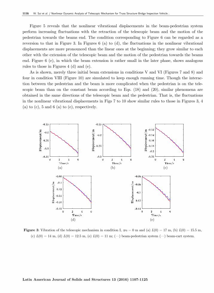
Figure 5 reveals that the nonlinear vibrational displacements in the beam-pedestrian system perform increasing fluctuations with the retraction of the telescopic beam and the motion of the pedestrian towards the beams end. The condition corresponding to Figure 6 can be regarded as a reversion to that in Figure 3. In Figures 6 (a) to (d), the fluctuations in the nonlinear vibrational displacements are more pronounced than the linear ones at the beginning; they grow similar to each other with the extension of the telescopic beam and the motion of the pedestrian towards the beams end. Figure 6 (e), in which the beam extension is rather small in the later phase, shows analogous rules to those in Figures 4 (d) and (e).
As is shown, merely three initial beam extensions in conditions V and VI (Figures 7 and 8) and four in condition VIII (Figure 10) are simulated to keep enough running time. Though the interac-tion between the pedestrian and the beam is more complicated when the pedestrian is on the tele-scopic beam than on the constant beam according to Eqs. (18) and (20), similar phenomena are obtained in the same directions of the telescopic beam and the pedestrian. That is, the fluctuations in the nonlinear vibrational displacements in Figs 7 to 10 show similar rules to those in Figures 3, 4 (a) to (c), 5 and 6 (a) to (e), respectively.
(a) (b) (c)
(d) (e)
Figure 3: Vibration of the telescopic mechanism in condition I, zP0 = 0 m and (a) L(0) = 17 m, (b) L(0) = 15.5 m,
(c) L(0) = 14 m, (d) L(0) = 12.5 m, (e) L(0) = 11 m; (—) beam-pedestrian system (—) beam-cart system.

W. Sui et al. / Nonlinear Dynamic Analysis of Telescopic Mechanism for Truss Structure Bridge Inspection Vehicle… 1117
Latin American Journal of Solids and Structures 13 (2016) 1107-1125
(a) (b) (c)
(d) (e)
Figure 4: Vibration of the telescopic mechanism in condition II, zP0 = 10 m and (a) L(0) = 17 m, (b) L(0) = 15.5 m,
(c) L(0) = 14 m, (d) L(0) = 12.5 m, (e) L(0) = 11 m; (—) beam-pedestrian system, (—) beam-cart system.
(a) (b) (c)
(d) (e)
Figure 5: Vibration of the telescopic mechanism in condition III, zP0 = 0 m and (a) L(0) = 20 m, (b) L(0) = 18.5 m,
(c) L(0) = 17 m, (d) L(0) = 15.5 m, (e) L(0) = 14 m; (—) beam-pedestrian system (—) beam-cart system.

1118 W. Sui et al. / Nonlinear Dynamic Analysis of Telescopic Mechanism for Truss Structure Bridge Inspection Vehicle…
Latin American Journal of Solids and Structures 13 (2016) 1107-1125
(a) (b) (c)
Time/s0 2 4 6
-0.18
-0.16
-0.14
-0.12
-0.1
-0.08
(d) (e)
Figure 6: Vibration of the telescopic mechanism in condition IV, zP0 = 10 m and (a) L(0) = 20 m, (b) L(0) = 18.5 m,
(c) L(0) = 17 m, (d) L(0) = 15.5 m, (e) L(0) = 14 m; (—) beam-pedestrian system (—) beam-cart system.
(a) (b) (c)
Figure 7: Vibration of the telescopic mechanism in condition V, zP0 = 11 m and (a) L(0) = 17 m, (b) L(0) = 15.5 m,
(c) L(0) = 14 m; (—) beam-pedestrian system (—) beam-cart system.
(a) (b) (c)
Figure 8: Vibration of the telescopic mechanism in condition VI, (a) zP0 = 17 m, L(0) = 17 m, (b) zP0 = 15.5 m,
L(0) = 15.5 m, (c) zP0 = 14 m, L(0) = 14 m; (—) beam-pedestrian system (—) beam-cart system.

W. Sui et al. / Nonlinear Dynamic Analysis of Telescopic Mechanism for Truss Structure Bridge Inspection Vehicle… 1119
Latin American Journal of Solids and Structures 13 (2016) 1107-1125
(a) (b) (c)
(d) (e)
Figure 9: Vibration of the telescopic mechanism in condition VII, zP0 = 11 m and (a) L(0) = 20 m, (b) L(0) = 18.5 m,
(c) L(0) = 17 m, (d) L(0) = 15.5 m, (e) L(0) = 14 m; (—) beam-pedestrian system (—) beam-cart system.
(a) (b)
(c) (d)
Figure 10: Vibration of the telescopic mechanism in condition VIII, (a) zP0 = 20 m, L(0) = 20 m, (b) zP0 = 18.5 m,
L(0) = 18.5 m, (c) zP0 = 17 m, L(0) = 17 m, (d) zP0 = 15.5 m, L(0) = 15.5 m; (—)
beam-pedestrian system (—) beam-cart system.

1120 W. Sui et al. / Nonlinear Dynamic Analysis of Telescopic Mechanism for Truss Structure Bridge Inspection Vehicle…
Latin American Journal of Solids and Structures 13 (2016) 1107-1125
4 CONCLUSION
Nonlinear dynamic analysis of an axially moving telescopic mechanism for truss structure bridge inspection vehicle under pedestrian excitation is conducted. The nonlinear equations of motion for the beam-pedestrian system are established utilizing the Hamilton’s principle. Based on the nonlin-ear equations, the linear equations of motion for the beam-cart system are implemented. The solu-tions to the equations are acquired by applying the Galerkin’s method, the Newmark-β method in conjunction with the Newton-Raphson interaction method.
Numerical examples are presented to illustrate the differences between the dynamic responses of the telescopic mechanism under pedestrian excitation and corresponding moving cart. The results are concluded as follows:
(1) Compared with that in the beam-cart system, the displacement of the telescopic mecha-nism in the beam-pedestrian system is smaller especially when the pedestrian is close to the end of the beams.
(2) The vibration of the telescopic mechanism in the beam-pedestrian system is significantly stronger than that in the beam-cart system when the beam extension is small or when the pedestrian is close to the end of the beams. Nevertheless, the vibrations in the two sys-tems don’t differ a lot when the telescopic beam is in large extension and the pedestrian is far away from the beams end.
As a consequence, it can be drawn that simplification of the pedestrian as moving cart may lead to inaccuracy in evaluating the dynamic behaviors of the system. The results can be theore-tical support for correctly assessing the stability and further investigations into the telescopic mechanism under multiple pedestrians or more complicated conditions. Acknowledgements
This research was supported by the Program for Changjiang Scholars and Innovative Research Team in University (Grant No. IRT1292) and the Project Funded by the Priority Academic Program Development of Jiangsu Higher Education Institutions. The authors would like to thank the editors, associate editors and anonymous reviewers for their constructive comments.
References
An, C., Su, J., (2011). Dynamic response of clamped axially moving beams: Integral transform solution. Applied Mathematics and Computation 218: 249–259.
Bachmann, H., Ammann, W. (1987). Vibrations in structures induced by man and machines. 3rd Ed., International Association for Bridge and Structural Engineering (IABSE), Zurich, Switzerland.
Behdinan, K., Stylianoub, M.C., Tabarrokc, B., (1997). Dynamics of flexible sliding beams- non-linear analysis part I - formulation. Journal of Sound and Vibration 208: 517–539.
Behdinan, K., Tabarrok, B., (1997). Dynamics of flexible sliding beams – non-linear analysis part II: transient re-sponse. Journal of Sound and Vibration 208: 541–565.
Bocian, M., Macdonald, J.H.G., Burn, J.F., (2013). Biomechanically inspired modeling of pedestrian-induced vertical self-excited forces. Journal of Bridge Engineering 18: 1336–1346.
British Standards Institution (BSI). (2003). UK national annex to Eurocode 1: Actions on structures.

W. Sui et al. / Nonlinear Dynamic Analysis of Telescopic Mechanism for Truss Structure Bridge Inspection Vehicle… 1121
Latin American Journal of Solids and Structures 13 (2016) 1107-1125
Brownjohn, J.M.W., Fok, P., Roche, M., Omenzetter, P., (2004). Long span steel pedestrian bridge at Singapore Changi Airport – part 2: Crowd loading tests and vibration mitigation measures. Structural Engineer 82: 28–34.
Duan, Y.C., Wang, J.P., Wang, J.Q., (2014). Theoretical and experimental study on the transverse vibration proper-ties of an axially moving nested cantilever beam. Journal of Sound and Vibration 333: 2885–2897.
Fung, R.F., Lu, P.Y., Tseng, C.C., (1998). Non-linearly dynamic modelling of an axially moving beam with a tip mass. Journal of Sound and Vibration 218: 559–571.
Ingólfsson, E.T., Georgakis, C.T., Ricciardelli, F., Jönsson, J., (2011). Experimental identification of pedestrian-induced lateral forces on footbridges. Journal of Sound and Vibration 330: 1265–1284.
Ingólfsson, E.T., Georgakis, C.T., Svendsen, M.N. (2008). Vertical footbridge vibrations: Details regarding and exper-imental validation of the response spectrum methodology. Proceedings of the 3rd International Conference Foot-bridge 2008, Porto, Portugal.
Inman, V. T., Ralston, H. J., Todd, F. (1981). Human walking, Williams & Wilkins, Baltimore.
International Federation for Structural Concrete (fib). (2005). Guidelines for the design of footbridges.
International Organization for Standardization (ISO). (2007). Bases for design of structures: Serviceability of build-ings and walkways against vibrations.
Khalili, S.M.R., Jafari, A.A., Eftekhari, S.A., (2010). A mixed Ritz-DQ method for forced vibration of functionally graded beams carrying moving loads. Composite Structures 92: 2497–2511.
Liu, D., Xu, W., Xu, Y., (2012). Dynamic responses of axially moving viscoelastic beam under a randomly disordered periodic excitation. Journal of Sound and Vibration 331: 4044–4056.
Macdonald, J.H.G., (2009). Lateral excitation of bridges by balancing pedestrians. Proceedings of the Royal Society of London A 465: 1055–1073.
Masani, K., Kouzaki, M., Fukunaga, T., (2002). Variability of ground reaction forces during treadmill walking. Jour-nal of Applied Physiology 92: 1885–1890.
Michaltsos, G., Sophianopoulos, D., Kounadis, A.N., (1996). The effect of a moving mass and other parameters on the dynamic response of a simply supported beam. Journal of Sound and Vibration 19: 357–362.
Ouyang, H.J., (2011). Moving-load dynamic problems: A tutorial (with a brief overview). Mechanical Systems and Signal Processing 25: 2039–2060.
Öz, H.R., Pakdemiorli, M., Boyacm, H., (2001). Non-linear vibrations and stability of an axially moving beam with time-dependent velocity. Journal of Sound and Vibration 36, 107–115.
Park, S., Yoo, H.H., Chung, J., (2013). Eulerian and Lagrangian descriptions for the vibration analysis of a deploying beam. Journal of Mechanical Science and Technology 27: 2637–2643.
Raftoyiannis, I.G., Michaltsos, G.T., (2013). Dynamic behavior of telescopic cranes boom. International Journal of Structural Stability and Dynamics 13: 1350010.
Siddiqui, S.A.Q., Golnaraghi, M.F., Heppler, G.R., (1998). Dynamics of a flexible cantilever beam carrying a moving mass. Nonlinear Dynamics 15: 137–154.
Şimşek, M., (2010). Non-linear vibration analysis of a functionally graded Timoshenko beam under action of a mov-ing harmonic load. Composite Structures 92: 2532–2546.
Şimşek, M., Kocatürk, T., (2009). Nonlinear dynamic analysis of an eccentrically prestressed damped beam under a concentrated moving harmonic load. Journal of Sound and Vibration 320: 235–253.
Şimşek, M., Kocatürk, T., Akbaş, Ş.D., (2012). Dynamic behavior of an axially functionally graded beam under action of a moving harmonic load. Composite Structures 94: 2358–2364.
Technical Department for Transport, Roads and Bridges Engineering and Road Safety/French Association of Civil Engineering (SETRA/AFGC). (2006) Footbridges: Assessment of vibrational behaviour of footbridges under pedes-trian loading.

1122 W. Sui et al. / Nonlinear Dynamic Analysis of Telescopic Mechanism for Truss Structure Bridge Inspection Vehicle…
Latin American Journal of Solids and Structures 13 (2016) 1107-1125
Vu-Quoc L. S., (1995) Dynamics of sliding geometrically exact beams: large angle maneuver and parametric reso-nance. Computer Methods in Applied Mechanics and Engineering 120: 65–118.
Wang, L.H., Hu, Z.D., Zhong, Z., Ju, J.W., (2009). Hamiltonian dynamic analysis of an axially translating beam featuring time-variant velocity. Acta Mechanica 206: 149–161.
Wang, P.K.C., Wei, J.D., (1987). Vibrations in a moving flexible robot arm. Journal of Sound and Vibration 116: 149–160.
Wang, Y.j., Wei, Q.C., Shi, J., Long, X.Y., (2010). Resonance characteristics of two-span continuous beam under moving high speed trains. Latin American Journal of Solids and Structures 7: 185-199.
Zarfam, R., Khaloo, A.R., (2012). Vibration control of beams on elastic foundation under a moving vehicle and ran-dom lateral excitations. Journal of Sound and Vibration 331: 1217–1232.
Zhang, W., Sun, L., Yang, X.D., Jia, P., (2013). Nonlinear dynamic behaviors of a deploying and retreating wing with varying velocity. Journal of Sound and Vibration 332: 6785–6797.
Živanović, S., Pavić, A., Ingólfsson, E.T., (2010). Modeling spatially unrestricted pedestrian traffic on footbridges. Journal of Structural Engineering 136: 1296–1308.
Appendix A
The coefficients of the eigenfunctions in Eq. (16) are
1 2 3 4
1 1 1 2 2 2 3 3 3 4 4 4
1, , 1,
, , ,i i i i i i
i i i i i i i i i i i i i i i i
A A A A
B aa bb B aa bb B aa bb B aa bb
g gg g g g
= = =- =-= + = + = + = +
(A.1)
where
( ) ( ) ( ) ( )( ) ( ) ( ) ( )
1 2 2 2 2 2 3 2 2 4 2 2
1 2 2 2 2 2 3 2 2 4 2 2
cosh sinh cos sin
cosh sinh cos sin
i i e i i e i i e i i e
i
i i e i i e i i e i i e
aa L aa L aa L aa L
bb L bb L bb L bb L
b b b bg
b b b b
+ - -=-
+ - - (A.2)
( ) ( ) ( ) ( )( ) ( ) ( ) ( )( ) ( ) ( ) ( )( )
1 1 1 1 2 1 1 1 1 1 1 2 1 1
2 3 1 1 4 1 1 2 3 1 1 4 1 1
3 2 1 1 1 1 1 3 2 1 1 1 1 1
4 4 1 1 3 1
cosh cos sinh sin
sinh sin cosh cos
cosh cos sinh sin
sinh sin
i i i i i i i i i i
i i i i i i i i i i
i i i i i i i i i i
i i i i
aa c L c L bb c L c L
aa c L c L bb c L c L
aa c L c L bb c L c L
aa c L c
b b b b
b b b b
b b b b
b b
= - = +
= + = -
= - = -
= + ( ) ( ) ( )1 4 4 1 1 3 1 1cosh cos
i i i i i iL bb c L c Lb b= -
(A.3)
2 2 3 3
1 1 1 1 1 1 1 1 1 11 2 3 42 2 3 3
2 2 2 2 2 22 2 2 2
1 1 1 11 , 1 , ,
2 2 2 2i i i i i i
i i i i
i ii i i i
EI EI EI EIc c c c
EI EI EI EI
b b b b b b
b bb b b b
æ ö æ ö æ ö æ ö÷ ÷ ÷ ÷ç ç ç ç÷ ÷ ÷ ÷ç ç ç ç= + = - = + = -÷ ÷ ÷ ÷ç ç ç ç÷ ÷ ÷ ÷ç ç ç ç÷ ÷ ÷ ÷ç ç ç çè ø è ø è ø è ø (A.4)
Appendix B
The parameters in Eq. (18) are given as follows
( )( )
1 1
1 1
1 1 1 1 1 1 1 1 10 0
2
2 2 2 2 2 2 2 2 2 2 1
N 2
2
L L
e
L L
B B kL L
k
A dx m x L EI dx
A v v dx EI dx
r d
r
¢¢ ¢¢= + - +
¢ ¢¢ ¢¢ ¢¢+ + + + +
=
ò òò ò
K X X X X X X
X X X X X X X X S
K S
(B.1)

W. Sui et al. / Nonlinear Dynamic Analysis of Telescopic Mechanism for Truss Structure Bridge Inspection Vehicle… 1123
Latin American Journal of Solids and Structures 13 (2016) 1107-1125
( ) ( )
( )
( )
1
1
1
1
1
1
1 1 1 1 1 1 2 2 2 2 30
N 4
1 1 1 2 2 2 1 1 1 50
1 1 2 2 1 1 60
2 2 2L L
e B kL
kL L
e kL
L L
e kL
A dx m x L A v dx
A dx A dz m x L
Ag dx A g dx m g x L
r d r
r r d
r r d
¢= + - + + +
=
= + + - +
=- - - - +
ò ò
ò ò
ò ò
C X X X X X X X S
C S
M X X X X X X S
F X X X S
where Skp (k = 1,2; p = 1, 2,…, 6) represents the items from the pedestrian excitation
( )( )
( )
( )
22
1 P
2
2 P
22
3
2 sin cossin
cos cos 180
sin cos
sin cos2 sin
cos cos 180
Pk k
k P kP
TD k P
P
Pk k k k
Pk k
k P kP
TD k P
P
v
lm x xv
v t nf
mx x
lv
lmv
v t nf
q qq
dq q d
q qd
q qq
q q d
é ùê ú+ê úê ú= -æ öê ú÷ç ÷ê úç+ - - ÷ç ÷ê ú÷çè øê úë û
= - -
+= æ ö÷ç ÷ç+ - - ÷ç ÷çè ø
X XS X
X
S X X qX
X XS X
X
( )
( ) ( )
( )( )
P
2
4 P
25
2 2 3
6 P
2 sin cos
sin
1sin sin
sin cos 180 cot
Pk k k k k k
k P k k
P
k P kP
P TD P
P
x x
mx x
lm
g vl
m x xvv v t n
f
d
q qd
q
q qd
q q q d
é ùê úê úê ú -ê úê úê ú÷ê úë û
= - + -
=ì üï ïï ï-ï ïï ïï ï= - -í ýæ öï ï÷çé ù ÷ï ïç- - - - ÷ï ïçê ú ÷ë ûï ï÷çè øï ïî þ
S X X qX X qX
S X X
S X
(B.2)
in which the differential of X1i and X2i with respect to time are expressed as
( ) ( ) ( ) ( )( ) ( ) ( ) ( )
1 1 2 1 1 1 1 2 1
3 4 1 1 3 1 4 1
cosh sinh
cos sini i i i i i i i i
i i i i i i i i
X A A x x A x A x
A A x x A x A x
b b b b
b b b b
= + + +
+ + + - +
(B.3)
( ) ( )( ) ( )( ) ( )( ) ( )
2 2
1 1 2 1 2 1 1 1 1
2 22 1 1 1 1 2 1 1
2 2
3 4 1 4 1 3 1 1
2 2
4 3 1 3 1 4 1 1
2 c os h
2 s in h
2 cos
2 sin
i i i i i i i i i
i i i i i i i i
i i i i i i i i
i i i i i i i i
X A A x A x A x x
A A x A x A x x
A A x A x A x x
A A x A x A x x
b b b b
b b b b
b b b b
b b b b
= + + +
+ + + +
+ + + -
+ - - -
(B.4)
( ) ( )( )( ) ( )( )( ) ( )( )( ) ( )( )
2 1 2 2 1 2 2 2 1
2 1 2 1 1 2 2 1
3 4 2 1 4 2 2 1
4 3 2 1 3 2 2 1
c os h
s in h
cos
sin
i i i i i i B i
i i i i i B i
i i i i i B i
i i i i i B i
X B B x L B v x L
B B x L B v x L
B B x L B v x L
B B x L B v x L
b b b
b b b
b b b
b b b
é ù= + - + -ê úë ûé ù+ + - + -ê úë ûé ù+ + - + -ê úë ûé ù+ - - - -ê úë û
(B.5)

1124 W. Sui et al. / Nonlinear Dynamic Analysis of Telescopic Mechanism for Truss Structure Bridge Inspection Vehicle…
Latin American Journal of Solids and Structures 13 (2016) 1107-1125
( )( ) ( )( )
( )
( )( ) ( )( )
( )( )
2
1 1 2 1 2 2 2 12 2 1
2 2 1 2 2 2 2
2
2 2 2 1 2 1 2 12 1
1 2 1 1 2 1 2
2cosh
2 2
2sinh
2 2
i i i i B i ii i
i i i i B i i B
i i B i ii
i i i i B i i B
B B x L v B x LX x L
B x L B v B v
B B x L v B x Lx L
B x L B v B v
b b bb
b b b
b b bb
b b b
é ù+ - + + -ê ú
= -ê úê ú+ - + +ê úë ûé ù
+ - + + -ê ú+ -ê ú
ê ú+ - + +ê úë û
+
( )( ) ( )( )
( )( )
( )( ) ( )( )
( )( )
2
3 3 2 1 2 4 2 12 1
4 2 1 4 2 4 2
2
4 4 2 1 2 3 2 12 1
3 2 1 3 2 3 2
2cos
2 2
2sin
2 2
i i i i B i ii
i i i i B i i B
i i i i B i ii
i i i i B i i B
B B x L v B x Lx L
B x L B v B v
B B x L v B x Lx L
B x L B v B v
b b bb
b b b
b b bb
b b b
é ù- - + + -ê ú
-ê úê ú+ - + +ê úë ûé ù
- - + - -ê ú+ -ê ú
ê ú- - - -ê úë û
(B.6)
The differential of X1Pi and X2Pi with respect to time at the position of the pedestrian are expressed as
( ) ( ) ( ) ( )( ) ( ) ( ) ( )
1 1 2 1 2 1 1 2 1 1 1 1 1
3 4 1 4 1 1 4 3 1 3 1 1
cosh sinh
cos sinPi i i i P i i P i P i i i P i i P i P
i i i P i i P i P i i i P i i P i P
X A A x A v x A A x A v x
A A x A v x A A x A v x
b b b b b b
b b b b b b
= + + + + +
+ + + + - -
(B.7)
( ) ( )
( ) ( )
( )
2
1 1 1 1 1 2 1 2 1 2 1 2 1 1
2
2 2 1 1 1 1 1 1 1 1 1 1 1
2
3 3 1 1
2 2 2 cosh
2 2 2 sinh
Pi i i i P i P i i P i i P i i P i i P i P
i i i P i P i i P i i P i i P i i P i P
i i i P i P
X A A x v A x A x A v A v x
A A x v A x A x A v A v x
A A x v
b b b b b b b
b b b b b b b
b b
é ù= + + + + + +ê ú
ê úë ûé ù
+ + + + + + +ê úê úë û
+ - + +
( )
( ) ( )4 1 4 1 4 1 4 1 1
2
4 4 1 1 3 1 3 1 3 1 3 1 1
2 2 2 cos
2 2 2 sin
i i P i i P i i P i i P i P
i i i P i P i i P i i P i i P i i P i P
A x A x A v A v x
A A x v A x A x A v A v x
b b b b b
b b b b b b b
é ù+ + +ê ú
ê úë ûé ù
+ - + - - - -ê úê úë û
(B.8)
( ) ( )( )( ) ( )( )( ) ( )( )( ) ( )( )
2 1 2 2 1 2 2 2 1
2 1 2 1 1 2 2 1
3 4 2 1 4 2 2 1
4 3 2 1 3 2 2 1
cosh
sinh
cos
sin
Pi i i i P i i i P
i i i P i i i P
i i i P i i i P
i i i P i i i P
X B B x L B v x L
B B x L B v x L
B B x L B v x L
B B x L B v x L
b b b
b b b
b b b
b b b
é ù= + - + -ê úë ûé ù+ + - + -ê úë ûé ù+ + - + -ê úë ûé ù+ - - - -ê úë û
(B.9)
( ) ( ) ( )( )
( )( )
( ) ( )( )
2
1 1 2 1 2 2 2 12 2 1
2 2 1 2 2 2 2
2
2 2 2 1 2 1 2 1
1 2 1 1 2 1 2
2, cosh
2 2
2
2 2
i i i P i i i PPi i P
i i P i i i i
i i i P i i i P
i i P i i i i
B B x L v B x LX x t x L
B x L B v B v
B B x L v B x L
B x L B v B v
b b bb
b b b
b b b
b b b
ì üï ïé ùï ï+ - + + -ï ïê úë û= -í ýï ï+ - + +ï ïï ïî þì é ù+ - + + -ê úë û++ - + +
( )( )
( ) ( )( )
( )( )
( ) ( )( )
2 1
2
3 3 2 1 2 4 2 12 1
4 2 1 4 2 4 2
2
4 4 2 1 2 3 2 1
3 2 1
sinh
2cos
2 2
2
2
i P
i i i P i i i Pi P
i i P i i i i
i i i P i i i P
i i P
x L
B B x L v B x Lx L
B x L B v B v
B B x L v B x L
B x L
b
b b bb
b b b
b b b
b
üï ïï ïï ï -í ýï ïï ïï ïî þì üï ïé ùï ï- - + + -ï ïê úë û+ -í ýï ï+ - + +ï ïï ïî þ
é ù- - + - -ê úë û+- - -
( )( )2 1
3 2 3 2
sin2
i P
i i i i
x LB v B v
bb b
ì üï ïï ïï ï -í ýï ï-ï ïï ïî þ
(B.10)

W. Sui et al. / Nonlinear Dynamic Analysis of Telescopic Mechanism for Truss Structure Bridge Inspection Vehicle… 1125
Latin American Journal of Solids and Structures 13 (2016) 1107-1125
Appendix C
The parameters in Eq. (20) are given as follows
( )( )
( ) ( )
1 1
1 1
1
1
1
1
1 1 1 1 1 1 1 1 10 0
2
2 2 2 2 2 2 2 2 2 2 1
1 1 1 1 1 1 2 2 2 2 20
1 1 1 2 2 20
d d
A 2 d d
2 d 2 2 d +
d d
L L
C e
L L
B B kL L
L L
C e B kL
L L
C eL
A x m x L EI x
v v x EI x
A x m x L A v x
A x A x m
r d
r
r d r
r r
¢¢ ¢¢= + - +
¢ ¢¢ ¢¢ ¢¢+ + + + +
¢= + - + +
= + +
ò òò ò
ò ò
ò ò
K X X X X X X
X X X X X X X X R
C X X X X X X X R
M X X X X X
( )
( )1
1
1 1 1 3
1 1 2 2 1 1 40
+
= g d g d g
k
L L
C e kL
x L
A x A x m x L
d
r r d
-
- - - - +ò ò
X R
F X X X R
(C.1)
where
( )( )( )( )
1 P
2 P
3 P
4 P
1,2
2 1,2
1,2
1,2
k P k k
k P k k
k P k k
k P k
m x x k
m x x k
m x x k
m g x x k
d
d
d
d
= - =
= - =
= - =
=- - =
R X X
R X X
R X X
R X
(C.2)