nonlinear gain amplification due to two-wave mixing in a broad-area semiconductor amplifier with...
TRANSCRIPT

Nonlinear gain amplification due to two-wave mixing in a broad-area semiconductor amplifier
with moving gratings Mingjun Chi,1* Jean-Pierre Huignard,2 and Paul Michael Petersen1
1Department of Photonics Engineering, Technical University of Denmark, P.O. Box 49, DK-4 000 Roskilde, Denmark 2Thales Research & Technology, RD 128 91767, Palaiseau Cedex, France
*corresponding author: [email protected]
Abstract: The two-wave mixing in a broad-area semiconductor amplifier with moving gratings is investigated theoretically, where a pump beam and a signal beam with different frequencies are considered, thus both a moving phase grating and a moving gain grating are induced in the amplifier. The coupled-wave equations of two-wave mixing are derived based on the Maxwell’s wave equation and rate equation of the carrier density. The analytical solutions of the coupled-wave equations are obtained in the condition of small signal when the total intensity is far below the saturation intensity of the amplifier. The results show that the optical gain of the amplifier is affected by both the moving phase grating and the moving gain grating, and there is energy exchange between the pump and signal beams. Depending on the moving direction of the gratings and the anti-guiding parameter, the optical gain may increase or decrease due to the two-wave mixing.
©2008 Optical Society of America
OCIS codes: (140.5960) Semiconductor lasers; (140.3280) Laser amplifiers; (190.7070) Two-wave mixing
References and Links
1. H. Nakajima and R. Frey, “Collinear nearly degenerate four-wave mixing in intracavity amplifying media,” IEEE J. Quantum Electron. 22, 1349-1354 (1986).
2. P. Kürz, R. Nagar, and T. Mukai, “Highly efficient phase conjugation using spatially nondegenerate four-wave mixing in a broad-area laser diode,” Appl. Phys. Lett. 68, 1180-1182 (1996).
3. M. Lucente, G. M. Carter, and J. G. Fujimoto, “Nonlinear mixing and phase conjugation in broad-area diode lasers,” Appl. Phys. Lett. 53, 467-469 (1988).
4. M. Lucente, J. G: Fujimoto, and G. M. Carter, “Spatial and frequency dependence of four-wave mixing in broad-area diode lasers,” Appl. Phys. Lett. 53, 1897-1899 (1988).
5. D. X. Zhu, S. Dubovitsky, W. H. Steier, K. Uppal, D. Tishinin, J. Burger, and P. D. Dapkus, “Noncollinear four-wave mixing in a broad area semiconductor optical amplifier,” Appl. Phys. Lett. 70, 2082-2084 (1997).
6. P. M. Petersen, E. Samsøe, S. B. Jensen, and P. E. Andersen, “Guiding of laser modes based on self-pumped four-wave mixing in a semiconductor amplifier,” Opt. Express 13, 3340-3347 (2005).
7. P. Günter and J.-P. Huignard, eds., Photorefractive Materials and Their Applications I and II, (Springer-Verlag, Berlin, 1988, 1989).
8. A. Brignon and J.-P. Huignard, “Two-wave mixing in Nd:YAG by gain saturation,” Opt. Lett. 18, 1639-1641 (1993).
9. M. Chi, S. B. Jensen, J.-P. Huignard, and P. M. Petersen, “Two-wave mixing in a broad-area semiconductor amplifier,” Opt. Express 14, 12373-12379 (2006).
10. G. P. Agrawal, “Four-wave mixing and phase conjugation in semiconductor laser media,” Opt. Lett. 12, 260-262 (1987).
11. J. R. Marciante and G. P. Agrawal, “Nonlinear mechanisms of filamentation in broad-area semiconductor lasers,” J. Quantum Electron. 32, 590-596 (1996).
#92835 - $15.00 USD Received 15 Feb 2008; revised 28 Mar 2008; accepted 31 Mar 2008; published 4 Apr 2008
(C) 2008 OSA 14 April 2008 / Vol. 16, No. 8 / OPTICS EXPRESS 5565
1. Introduction
Nonlinear four-wave mixing in narrow-stripe and broad-area semiconductor lasers is of interest as a method to obtain high phase conjugate reflectivity.[1,2] The nonlinear wave mixing can also be used to measure carrier dynamics and gain behavior directly in the device, as well as for understanding device physics and application.[3-5] The gain and index gratings created in broad-area semiconductor amplifiers by coherent wave mixing are very interesting nonlinear interactions which may apply to realize high brightness semiconductor lasers as well as to study the carriers dynamics and the physics of the devices.[6] Although two-wave mixing (TWM) has been intensively investigated in photorefractive materials, [7] only few works was done in gain media. [8] Recently, we investigated the TWM in a broad-area semiconductor amplifier, both theoretically and experimentally, where the frequency of the pump beam and the signal beam are the same, thus a static phase grating and a static gain grating in the semiconductor amplifier are induced. [9] The results show that the optical gain of both beams is decreased due to the induced gain grating, the phase grating does not affect the optical gain; there is no energy exchange between the pump and signal beams. [9]
Here, we present the theoretical results of TWM in a broad-area semiconductor amplifier with moving gratings, i.e., the frequencies of the pump beam and the signal beam are different. Unlike the condition of static gratings, both a moving phase gating and a moving gain grating affect the optical gain of the amplifier. The coupled-wave equations of two-wave mixing are derived. The analytical solutions to the coupled-wave equations are obtained in the condition of small signal and the total intensity is far below the saturation intensity. We find the optical gain can be increased or decreased due to the TWM, and there is energy exchange between the pump and signal beams. The aim of the presented theory is to study the physics of the device, and to analyze the different contributions from phase grating and gain grating to the TWM gain. The parameters of the device, such as the saturation intensity of the device Ps, the diffusion constant D, [9] the anti-guiding parameter β and the spontaneous recombination lifetime τ, can be obtained by fitting the experimental result with the analytical results.
2. Theory of TWM in broad-area semiconductor amplifier with moving gratings
Z=0
Z=Z0
A1
Z Semiconductor amplifier
Moving gratings
Electrode
A2
x
K
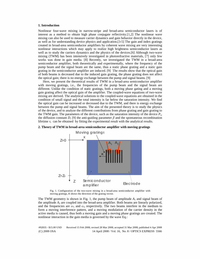
Fig. 1. Configuration of the two-wave mixing in a broad-area semiconductor amplifier with moving gratings, K shows the direction of the grating vector.
The TWM geometry is shown in Fig. 1, the pump beam of amplitude A1 and signal beam of the amplitude A2 are coupled into the broad-area amplifier. Both beams are linearly polarized, and the frequencies are ω1 and ω2 respectively. The two beams interfere in the medium to form a moving interference pattern, and a moving modulation of the carrier density in the active media is caused, thus both a moving gain and a moving phase gratings are created. The nonlinear interaction in the gain media is governed by the wave Eq.:
#92835 - $15.00 USD Received 15 Feb 2008; revised 28 Mar 2008; accepted 31 Mar 2008; published 4 Apr 2008
(C) 2008 OSA 14 April 2008 / Vol. 16, No. 8 / OPTICS EXPRESS 5566

2
2
20
2
2
2
22 1
t
P
ct
E
c
nE
∂∂=
∂∂−∇
ε, (1)
where n is the refractive index of the semiconductor material, and c is the velocity of light in vacuum, and the ε0 is the vacuum permittivity. The total electric field is given by: [9,10]
)(2
)(1
2211 trKitrKi eAeAE ωω −⋅−⋅ += , (2)
where K1 and K2 are the wave vectors of the pump and signal beam in the amplifier. P is the induced polarization in the semiconductor amplifier. It is given by: [9,10]
ENP )(0 χε= , (3)
where the susceptibility χ is given by: [9,10]
)()()( Nginc
N +−= βω
χ , (4)
the quantity β is the anti-guiding parameter accounting for the carrier-induced index change in semiconductor amplifier, and g(N) is the gain that is assumed to vary linearly with carrier density N, i.e., g(N)=Γa(N-N0) where a is the gain cross-section, Γ is the confinement factor, and N0 is the carrier density at transparency.
The carrier density N is governed by the following rate Eq. [6]:
ωτ �
2
2 )(E
NgNDN
qV
I
dt
dN −∇+−= , (5)
where I is the injected current, q is the electron charge, V is the active volume, τ is the spontaneous recombination lifetime, D is the ambipolar diffusion constant. In the TWM configuration the origin of the gain and index gratings is the modulation of the carrier density due to the interference between A1 and A2. Thus the carrier density that leads to the formation of the moving gratings may be written as:
[ ] [ ])(exp)(exp * tKxiNtKxiNNN B δδ −Δ++−Δ+= , (6)
where NB is the average carrier density, ΔN is the induced carrier modulation. K=K2-K1=4πsin((θ1-θ2)/2) is the grating vector; θ1 is the angle between the pump beam and Z axis, and θ2 is the angle between the signal beam and Z axis; we assume θ1 = -θ2, thus the direction of the grating vector is in the X direction. δ=ω2-ω1 is the frequency difference between the single and pump beams. In the following perturbation analysis it is assumed that ΔN << NB. Inserting Eqs. (2) and (6) into Eq. (5), we find after some simple calculations that the average carrier density NB and the carrier modulation ΔN are given by:
s
sB
PE
PENqVIN
2
0
2
00
1+
+=
τ, (7)
( )
δττ iPEKD
PAANNN
s
sB
+++−
−=Δ2
02
*210
1, (8)
#92835 - $15.00 USD Received 15 Feb 2008; revised 28 Mar 2008; accepted 31 Mar 2008; published 4 Apr 2008
(C) 2008 OSA 14 April 2008 / Vol. 16, No. 8 / OPTICS EXPRESS 5567

where 2
2
2
1
2
0 AAE += is the average intensity, and )()( τω aPs Γ= � is the
saturation intensity. Inserting Eqs. (2) and (3) into Eq. (1), and using the obtained results of the average carrier
density NB and carrier modulation ΔN, after some calculations, the coupled-wave equations for two-wave mixing with moving gratings are obtained:
01
11
)(cos 12
02
2
22
0
11 =
⎟⎟
⎠
⎞
⎜⎜
⎝
⎛
+++−
⎥⎥⎦
⎤
⎢⎢⎣
⎡
++−−
∂∂
AiPEKD
PA
PE
ii
z
A
s
s
s δττβαθ , (9)
01
11
)(cos 22
02
2
12
0
22 =
⎟⎟
⎠
⎞
⎜⎜
⎝
⎛
−++−
⎥⎥⎦
⎤
⎢⎢⎣
⎡
++−−
∂∂
AiPEKD
PA
PE
ii
z
A
s
s
s δττβαθ , (10)
where α=Γa(Iτ/qV-N0)/2 is the small-signal gain coefficient of the amplifier. Since the refractive index of the semiconductor material is high, normally the angles θ1(or θ2) is less than 2º in experiment;[9] so the cosine factor in Eqs. (9) and (10) is neglected below. Unlike the condition when the pump and signal beams have the same frequency, and only static gratings are generated; the coupling term between the two beams has different contribution to the optical gain of this two beams. [9]
In the small signal approximation, and if we assume that the total intensity of the beams is
much less than the saturation intensity, i.e., sPAA <<<< 2
1
2
2 , the terms accounting for
saturation in the denominator and the term accounting for the coupling in Eq. (9) may be neglected. Thus the coupled-wave equations can be solved analytically. The solutions are:
[ ]ziAA αβ )1(exp101 −= , (11)
[ ])2/)1()(1(exp 21202 −−−= zeziAA αγαβ , (12)
where A10 and A20 are the amplitudes of pump and signal beam at the front facet of the amplifier. γ1 is a parameter defined as:
( )⎟⎟⎠⎞
⎜⎜⎝
⎛
−++=
δττγ
iKDP
A
s2
2
101 1
11 . (13)
The first term in Eq. (13) is for the saturation effect, the second term is for the beam coupling. Define the TWM gain of the signal beam gTWM as the natural logarithm of the ratio of the
output intensity of signal with the coherent pump to that with the non-coherent pump:
222
22
10
2
01
2
pumptnoncoheren02
2
pumpcoherent02
TWM )()1(
1)(
)(
)(ln
δττβδττ
++++−
−=⎟⎟⎟⎟
⎠
⎞
⎜⎜⎜⎜
⎝
⎛
=KD
KD
P
AzA
zA
zAg
s
’ (14)
where z0 is the length of the semiconductor amplifier. The non-coherent pump means the pump beam is not coherent with the signal beam, but the intensity is the same as the coherent pump, thus the term accounting for saturation in Eq. (14) vanishes. In experiment, the coherent pump and the non-coherent pump can be achieved by changing the polarization of the pump beam. [9] Equation (14) shows that gTWM changes linearly with the output intensity
#92835 - $15.00 USD Received 15 Feb 2008; revised 28 Mar 2008; accepted 31 Mar 2008; published 4 Apr 2008
(C) 2008 OSA 14 April 2008 / Vol. 16, No. 8 / OPTICS EXPRESS 5568

(power) of the pump, and it decreases quickly when the angle between the two beams increases because the diffusion of carriers washes out the gratings as the angle between the two beams increases. This is the same as the situation when the pump and signal beams have the same frequency, and only static gratings are generated. [9] Equation (14) also shows that depending on the detuning frequency δ, the TWM gain can be positive or negative no matter
the amplifier is operated above or below the transparency (i.e., 2
10
2
01 )( AzA = ) . This is
different from the situation of static gratings. [9] This new phenomenon will be discussed below.
3. Calculation and discussion
Figure 2 shows the calculated results of the dependence of gTWM on the frequency difference δ with different anti-guiding parameter β, here we assume that the amplifier is operated above the transparent current. In the calculation, we use the same parameters used in and obtained from the TWM experiment in a GaAlAs broad-area amplifier with static gratings; [9] i.e.,
2
01 )(zA = 48.8 mW, 2
10A = 9.1 mW, Ps = 220 mW, Dτ = 4.1 μm2, K = 0.51 μm-1 (the K
number corresponds to a 1.2º angle between the two beams). Assuming that τ is 5 ns.11 From Fig. 2 we can find that when δ = 0, the gTWM is negative and independent of β; if β = 0, the gTWM is always negative and the curve of TWM gain versus δ is symmetric around the axis of δ = 0. If β ≠ 0, however, the gTWM is negative when δ > 0, and the gTWM can be negative or positive when δ < 0. These properties can be explained by using the relative position of the interference pattern, the carrier density grating, the index grating and gain grating formed in the broad-area amplifier.
-1,0 -0,6 -0,2 0,2 0,6 1,0-0,3
-0,2
-0,1
0,0
0,1
0,2
g TW
M
δ (GHz)
β=0 β=2 β=3 β=4 β=5
Fig. 2. The two-wave mixing gain gTWM versus δ with different anti-guiding parameter β according to Eq. (14).
Since the frequencies of the pump and signal are different, a moving interference pattern is
generated in the amplifier: ( )..)(*21
2
0
2cceAAEE tKxi ++= +− δ . Inserting Eq. (8) into Eq.
(6), the carrier density is obtained:
( ) [ ]⎟⎟
⎠
⎞
⎜⎜
⎝
⎛++−
+++−
−+= ..)(exp1
2
02
*210 cctKxi
iPEKD
PAANNNN
s
sBB δ
δττ.
The modulation part Nm of the carrier density for the generating of gain and phase gratings is:
#92835 - $15.00 USD Received 15 Feb 2008; revised 28 Mar 2008; accepted 31 Mar 2008; published 4 Apr 2008
(C) 2008 OSA 14 April 2008 / Vol. 16, No. 8 / OPTICS EXPRESS 5569

( )( ) ( )
[ ] ..)(exp1 222
02
0*21 cctKxi
PEKD
PNNAAN
s
sBm +−++−
+++
−= θπδ
δττ, (15)
where
sPEKDarctg
2
021 ++
=τ
δτθ (-π/2 <θ < π/2). (16)
Eq. (15) shows, because of the hole-burning effect and the finite response time of the material, there is a phase difference π-θ between the interference pattern and the carrier density grating. Since the gain varies linearly with carrier density, the gain grating Δg is also π-θ out of phase with the intensity pattern, i.e.,
( )( ) ( )
[ ] ..)(exp1
2 222
02
*210 cctKxi
PEKD
AA
P
NNag
ss
B +−++−+++
−Γ=Δ θπδδττ
. (17)
The refractive index grating is π out of phase with the gain grating because of the anti-guiding effect, so the refractive index grating Δn is –θ out of phase with the intensity pattern and proportional to the anti-guiding parameter β, i.e.,
( )( ) ( )
[ ] ..)(exp14 222
02
*210 cctKxi
PEKD
AA
P
NNan
ss
B +−+−+++
−Γ=Δ θδδττ
βπ
λ , (18)
λ is wavelength of the incident beams. The relative position of the interference pattern, the carrier density grating, the index grating and gain grating formed in the broad-area amplifier is shown in Fig. 3.
-3 0 3 6 9 12 15 180
1
2
3
4
5
6
7
8
π−θ
−θ
Gain pattern g(x)
Index pattern n(x)
Carrier density pattern N(x)
Intensity pattern I(x)
A.U
.
Lateral position
π−θ
Fig. 3. The relative position of the interference pattern, the carrier density grating, the index
grating and the gain grating formed in the BAA, assuming δττ =++ sPEKD2
021 ,
i.e., θ = π/4. The two-wave mixing gain caused by the gain grating ggain is:
#92835 - $15.00 USD Received 15 Feb 2008; revised 28 Mar 2008; accepted 31 Mar 2008; published 4 Apr 2008
(C) 2008 OSA 14 April 2008 / Vol. 16, No. 8 / OPTICS EXPRESS 5570

( ) ( )222
021
)cos(
δττ
θπ
+++
−∝s
gain
PEKDg . (19)
Here we should notice that the effect of the gain grating is the same for both beams, i.e., to increase (below transparent current) or decrease (above transparent current) the intensity of the pump and signal beams simultaneously, thus it will not cause the energy exchange between two beams. The two-wave mixing gain caused by the phase grating gphase is: [7]
( ) ( )222
021
)sin(
δττ
θβ
+++
−∝s
phase
PEKDg . (20)
When δ ≠ 0, the refractive index grating will cause energy exchange between two beams, since there is a phase difference -θ (θ ≠ 0) between the intensity pattern and the refractive index grating.7 The two-wave mixing gain gTWM is the sum of ggain and gphase.
When δ = 0, (i.e., static gratings are induced in the amplifier), θ is equal to zero; thus the gain grating is π out of phase with the interference pattern, and the phase grating is in phase with the interference pattern. According to Eqs (19) and (20), the gain of the phase grating gphase is zero; and the gTWM equal to ggain, is negative and independent of β.9 If β = 0, only the gain grating is generated, according to Eqs. (16) and (19), the two wave mixing gain gTWM is always negative and is symmetric around the axis of δ = 0. If β ≠ 0, both a gain and a phase grating are generated; when δ > 0 (θ > 0), according to Eqs. (19) and (20), both ggain and gphase are negative, so the gTWM is negative; when δ < 0 (θ < 0), the ggain is negative and the gphase is positive, so gTWM can be positive or negative.
The parameters β and τ can be obtained by fitting the measuring results of gTWM versus δ. The optimal δ to achieve the maximum TWM gain depends on the device parameters τ, D, β and the grating vector K. From Eq. (14), the optimal δ is
βτβτδ )11)(1( 22 +±+−= KDopt .
4. Conclusion
In conclusion, the two-wave mixing in broad-area semiconductor amplifier with moving gratings is investigated theoretically. The coupled-wave equations are derived and analytical solutions are obtained when the intensity of the pump is much larger than that of the single, but much less than the saturation intensity of the amplifier. The two-wave mixing gain is discussed based on the phase of the intensity pattern, carrier density grating, gain grating and refractive index grating. Depending on δ and β, the TWM gain can be positive or negative. The energy exchange between the pump and signal beams occurs when δ ≠ 0.
Acknowledgment
The authors wish to acknowledge the financial support of the European Community through the FP-6 project WWW.BRIGHTER.EU. Mingjun Chi wishes to acknowledge the Danish Research Agency under grant no. 26-04-0229.
#92835 - $15.00 USD Received 15 Feb 2008; revised 28 Mar 2008; accepted 31 Mar 2008; published 4 Apr 2008
(C) 2008 OSA 14 April 2008 / Vol. 16, No. 8 / OPTICS EXPRESS 5571