nonlinear structural dynamics for assessing aircraft...
TRANSCRIPT

Proceedings of the 9th International Conference on Structural Dynamics, EURODYN 2014
Porto, Portugal, 30 June - 2 July 2014
A. Cunha, E. Caetano, P. Ribeiro, G. Müller (eds.)
ISSN: 2311-9020; ISBN: 978-972-752-165-4
1989
ABSTRACT: The next generation of nuclear power plants is being designed worldwide with consideration for the effects of
impact from a large commercial aircraft as a malevolent act. Detailed, realistic nonlinear structural analyses are required to
assess the physical damage caused by an impact in order to meet regulatory requirements. In the U. S., industry developed
methodology for conducting aircraft impact analyses have been accepted by the U.S. Nuclear Regulatory Commission (NRC)
and requires advanced constitutive modeling of reinforced concrete, detailed and realistic structural modeling, appropriate
material failure criteria, and realistic application of the impact load using robust explicit dynamics analysis software. The most
common approach for load application is the Riera method that uses a force time history applied over a representative contact
area as a pressure load. Sample studies demonstrate that the Riera method offers good analytical results for structural
configurations that can fully resist the impact. For structural configurations that are insufficient to withstand the impact forces,
the Riera method is useful for assessing the failure mode of the impacted wall, but the method fails to quantify the consequences
of aircraft debris that penetrates beyond the initial point of impact. The sample studies also demonstrate that for some cases the
design-basis structure can adequately meet aircraft impact requirements. For other cases where reinforcement is minimal or the
span of the impacted wall is large, design enhancements can be made to offer the necessary resistance to limit damage to the
exterior wall. If the impacted wall fails, the consequences of debris entering the plant can be determined by an alternative
approach for load application called the missile-target interaction method. Further sample studies demonstrate that with this
approach, the aircraft can be explicitly modeled and used to investigate a realistic extent of damage, which may be acceptable.
KEY WORDS: Aircraft Impact; Nuclear Power Plants; Nonlinear Structural Dynamics; Advanced Concrete Material Modeling.
1 INTRODUCTION
The next generation of nuclear power plants is being designed
worldwide with consideration for the effects of impact from a
large commercial aircraft as a malevolent act. Nuclear power
plants have always had extremely robust designs considering
impacts from accidental and natural causes, such as tornado
driven debris or missiles generated from failures in high
energy systems within the plant, and even military aircraft if
sited near areas of frequent military maneuvers. Nuclear plant
designs also consider what if scenarios for large fires or
explosions from any cause that could damage an area of the
plant.
The new standards for consideration of intentional impacts
from large commercial aircraft are requiring detailed
structural modeling for damage assessments and detailed
system engineering assessments to quantify the consequences.
These structural and systems assessments are used to identify
design enhancements, if needed, for the plant to mitigate the
consequences of aircraft impact and maintain the plant in a
safe condition with minimal operator actions. This paper
focuses on the methods needed for assessing structural
performance in regards to aircraft impact.
2 METHODOLOGY
2.1 Structural Assessment Methods
The Nuclear Energy Institute (NEI) has issued document
number NEI 07-13 [1] that addresses methodology for
performing aircraft impact assessments of nuclear power
plants. A critical ingredient in the assessment of structural
response to aircraft impact is the constitutive model for
reinforced concrete, which must be highly detailed in its
representation of material behavior and numerically sound to
permit the calculation of severe damage. Also important is a
numerically robust explicit dynamics platform for capturing
eroding contact surfaces, managing rebar and concrete
interaction under severe cracking, and allowing efficient
computations of large problems. For this work, the ANACAP
concrete material model [3] coupled with the TeraGrande
explicit dynamics software [4] are employed. The concrete
material model has been extensively tested for loading leading
to extensive damage in reinforced concrete [5,6,7,8,9]. This
model was used extensively in EPRI research studies as the
basis for the structural methodology incorporated into NEI 07-
13, and is explicitly accepted for use in NEI 07-13.
2.2 Advanced Concrete Material Modeling
The behavior of concrete is highly nonlinear with small tensile
strengths, shear stiffness and strength that depend on crack
widths, and compressive capacity degradation after the
compressive strength is reached. Modeling of concrete
material, especially under conditions where extensive damage
can develop, requires advanced and detailed constitutive
models.
In the compression regime, the continuous stress-strain
curve is defined from uniaxial test data, which is then
Nonlinear structural dynamics for assessing aircraft impact
at nuclear power plants
Randy J. James1, Jeremy Wiesner2
1Sr. Associate and VP of Structures, ANATECH Corp., 5435 Oberlin Dr. San Diego, CA 92121 USA 2 Sr. Engineer, ANATECH Corp., 5435 Oberlin Dr. San Diego, CA 92121 USA
email: [email protected], [email protected]

Proceedings of the 9th International Conference on Structural Dynamics, EURODYN 2014
1990
generalized to multi-axial stress/strain states in the
conventional way using the effective stress and the effective
strain. The uniaxial behavior is generalized to multi-axial
behavior, within the analytical framework of isotropic-
hardening plasticity formulation, using a Drucker-Prager
surface to represent the loading surface under multi-axial
compression. In this formulation, the loading surface is a
function of the hydrostatic pressure, the second invariant of
the deviatoric stress tensor and the material yield strength.
This type of formulation is well suited for low to moderate
confinement stress levels, which typifies the behavior of civil
structures. Typical stress-strain curves for concrete under
monotonic and unconfined uniaxial compression show linear
behavior up to about 50% of its uniaxial compressive strength.
For stresses above this level, the material exhibits strain
hardening until it reaches its ultimate strength. When the
compressive strains are increased further, damage due to
crushing continues to accumulate, thus causing rapid strain
softening. Figure 1 shows the strain hardening and softening
behavior of the model for unconfined uniaxial loading.
Highly confined concrete exhibits considerably more strength
and ductility. For situations where significant concrete
confinement exists, such as impact on pre-stressed concrete
containments, the compressive concrete behavior is better
simulated using non-softening plastic flow since the material
can sustain larger compressive strains as well as increased
compressive strength.
Figure 1. Behavior of Unconfined Concrete in Uniaxial
Compression.
In the tension regime, cracking is mathematically treated at
the element integration points using an approach that is called
the smeared cracking model [10]. If cracking occurs, the
normal stress across the crack is reduced and the distribution
of stresses around the crack is recalculated. Cracks are
assumed to form perpendicular to the directions of largest
tensile strains, which exceed the cracking criterion. Multiple
cracks are allowed to form, but they are constrained to be
mutually orthogonal. Once a crack forms, the normal stress
across the crack is removed. The shear stiffness and stress is
also reduced upon cracking and further decays as the crack
opens. Once a crack forms, the direction of the crack remains
fixed and can never heal. However, a crack can close, resist
compression, and re-open under load reversals.
The concrete material model allows cracking to develop in
three directions at any material point as dictated by the state of
stress and strain. This allows stress redistribution and load
transfer to reinforcement or other load paths in the structure.
The cracking criterion, illustrated in Figure 2, forms a crack
when the generalized stress and strain state normal to the
crack exceeds the diagonal criterion line. Thus, cracking of
biaxial and triaxial stress states are treated consistently with
uniaxial cracking, but they occur at a slightly higher stress and
slightly lower strain. Split cracking occurs at near zero stress
and a tensile strain approximately twice that of uniaxial tensile
cracking. This agrees well with the observed behavior of
concrete test specimens.
Figure 2. Illustration of Crack Initiation Criteria
The surfaces of cracks that develop due to excess tensile
stress in concrete are usually rough and irregular. When a
shear force is applied along a crack, both tangential shear
sliding and normal displacements result. When the normal
displacement is restrained by rebars crossing the crack, tensile
stresses will develop in the reinforcement, which will then
induce compressive stresses across the crack. The resistance
to sliding is provided by the frictional force generated by the
compressive stress across the crack. This mechanism of shear
transfer in cracked concrete is called "interface shear
transfer". In order to take the shear stiffness of concrete into
account in the modeling, a reduced shear modulus is retained
in the stress-strain matrix. Al-Mahaidi [11] suggests a
hyperbolic variation of the shear modulus with the strain
normal to the crack, and a variation of this is used in the
ANACAP concrete model, as illustrated in Figure 3.
Figure 3. Modeling for Interface Shear Transfer
An important modeling consideration is the treatment of
shear stress across open cracks. The ANACAP model is
equipped with a shear shedding feature to limit the buildup of
shear stress across an open crack. The shear retention model
Proceedings of the 9th International Conference on Structural Dynamics, EURODYN 2014
1991
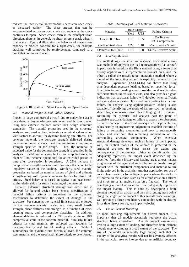
reduces the incremental shear modulus across an open crack
as discussed earlier. The shear stresses that can be
accommodated across an open crack also reduce as the crack
continues to open. Since cracks form in the principal strain
directions there is, in general, no shear across a crack when it
first opens. Figure 4 illustrates the behavior of shear stress
capacity in cracked concrete for a tight crack, for example
cracking well controlled by reinforcement, compared to a
crack that continues to open.
Figure 4. Illustration of Shear Capacity for Open Cracks
2.3 Material Properties and Failure Criteria
Impact of large commercial aircraft due to malevolent act is
considered a beyond-design-basis event and is thus treated
using best estimate methods rather than design minimum
standards. The material properties used in the structural
analyses are based on best estimate or nominal values along
with factors to account for dynamic loading rate effects. For
concrete material, the concrete strength delivered during
construction must always meet the minimum compressive
strength specified in the design. Thus, the nominal or
expected value for the compressive strength is specified in the
analysis. In addition, an aging factor can be applied since the
plant will not become operational for an extended period of
time after construction is completed. A 25% increase in
compressive strength is also allowed for rate effects due to the
impulsive nature of the loading. Similarly, steel material
properties are based on nominal values of yield and ultimate
strength along with dynamic increase factors for strain rate
effects. Steel behavior is based on typical nonlinear stress-
strain relationships for strain hardening of the material.
Because extensive structural damage can occur and is
allowed for beyond design basis events, specification of
material failure criteria is important in the structural
assessments to determine the extent of damage to the
structure. For concrete, the material limit states are enforced
by the concrete material model, e.g. very small tensile
strength, shear stiffness and strength as a function of crack
opening strain, and compressive plasticity. In addition,
element deletion is enforced for 5% tensile strain or 10%
compressive strain in the concrete material. Similarly, failure
criteria for steel material are enforced that accounts for
meshing fidelity and biaxial loading effects. Table 1
summarizes the dynamic rate factors allowed for common
steel material and the associated failure criteria to be enforced.
Table 1. Summary of Steel Material Allowances
Material Rate Factor
Failure Criteria Yield UTS
Grade 60 Rebar 1.10 1.05 5% Tension
10% Compression
Carbon Steel Plate 1.29 1.10 7% Effective Strain
Stainless Steel Plate 1.18 1.00 13.8% Effective Strain
2.4 Loading Methods
The methodology for structural response assessment allows
two methods of applying the load representative of an aircraft
impact; one is based on the Riera method using a force time
history applied over a representative contact area, and the
other is called the missile-target-interaction method where a
model of the impacting aircraft is explicitly included in the
analysis. Experience [12,13,14,15] has shown that using
time-dependent pressure loading, based on specified force-
time histories and loading areas, provides good results when
sufficient structural resistance exits, and also provides a good
indication that structural failure will develop when sufficient
resistance does not exist. For conditions leading to structural
failure, the analysis using applied pressure loading is also
capable of identifying the mode of failure, such as bending,
shear plug, compressive strut, plastic hinging, etc. However,
continuing the pressure load analysis past the point of
extensive structural damage or failure to assess the subsequent
extent of damage or structural consequences is possible, but
relies heavily on engineering judgment to establish the time of
failure or remaining momentum and how to subsequently
define and distribute this remaining momentum on the
surrounding structural components. When extensive
structural damage develops, such as failure of the impacted
wall, an explicit model of the aircraft is preferred in the
structural analyses to better assess the extent and
consequences of the damage. Using an aircraft model that
adequately represents the impact event described by the
specified force time history and loading areas allows natural
progression of damage and redistribution of loads through
contact with the structural components and material failure
limits enforced in the analysis. Another application for use of
an airplane model is for oblique impacts where the strike is
off-normal to the surface, such as for a roof strike on a curved
roof structure or an angled strike on a flat wall. The key is
developing a model of an aircraft that adequately represents
the impact loading. This is done by developing a finite
element model of an aircraft and then distributing mass points
along the length so that impact of this aircraft model on a rigid
wall provides a force time history compatible with the desired
force time history for a given impact velocity.
2.5 Finite Element Modeling
To meet licensing requirements for aircraft impact, it is
important that all models accurately represent the actual
structure being considered. Aircraft impact assessments
involve a large extent of loading, and therefore finite element
models must encompass a broad extent of the structure. The
size of the model is generally large enough such that the
quality of the analytical results will not be adversely affected
in the particular area of interest due to an artificial boundary

Proceedings of the 9th International Conference on Structural Dynamics, EURODYN 2014
1992
condition. The models have boundaries that represent cut
sections through walls, floor slabs, girders and columns of the
building. Displacement boundary conditions are enforced on
these cut surfaces with the intent to simulate the effect of the
remainder of the structure that is not included in the model.
The cut planes in the vertical direction are generally chosen at
locations that coincide with the mid-span of key structural
features such as floor slabs and girders. A roller type
boundary condition (displacement normal to the surface of the
cut) is applied to this type of cut plane. Typically just one cut
plane is required in the lateral direction and is generally
chosen at the top surface of a floor slab at or near grade. A
fully-fixed boundary condition is applied to this type of cut
plane to simulate the embedment of the structure into the
ground.
The finite element models are constructed using element
types that are considered standard practice for explicit
dynamic analyses. Concrete components of the structure are
modeled with 8-node hexahedral brick elements and
reinforcing bars are modeled with 2-node “truss like”
elements that are embedded in the solid elements. Each
individual reinforcing bar is explicitly included in the model.
In addition, 4-node quadrilateral shell elements and 2-node
beam elements are used as necessary to model other
components of the structure.
3 STUDY ASSESSMENTS
Example results are provided to illustrate the methods
employed for aircraft impact assessment. The loading used in
these studies is arbitrary and was developed to demonstrate
the modeling and analysis methodology; however, it is
considered representative of a large commercial aircraft.
Similarly, the structural configurations considered are
arbitrary and for illustration only, but are considered
representative of typical reinforced concrete configurations
used in nuclear power plants.
3.1 Finite Element Study Model
A single finite element model was constructed with large
enough extents so that multiple strike locations could be
considered to demonstrate a variety of structural
configurations and impact scenarios. The geometry of this
particular model is arbitrary but is representative of the spent
fuel pool (SFP) area of a typical nuclear power plant. An
illustration of the finite element model is provided in Figure 5
showing a cut section view of the complete model. Two strike
locations are considered for the study cases which are
indicated in the figure with red arrows.
The lower strike location is positioned vertically at the
midpoint between floor slabs and laterally at the midpoint
between transverse interior walls. This impacted bay is
representative of a typical size wall that spans one floor
vertically and about two to three times this distance in the
lateral direction. The upper strike location is positioned at the
midpoint of the span of the external wall above the spent fuel
pool. This impacted bay is representative of a large size wall
and is therefore particularly vulnerable to aircraft impact.
Figure 5. Section Cut View of Finite Element Study Model
The rebar included in the finite element model is illustrated
in Figure 6, which shows the complete model. The
reinforcement considered in the impacted wall varies
depending on the strike location and is discussed later for each
corresponding scenario. All of the other concrete components
in the model include a nominal amount of reinforcement that
is consistent with typical reinforcing schemes for nuclear
power plants.
Figure 6. Illustration of Rebar in Study Model
3.2 Strike on Typical Wall Span
This example examines the structural response of a typical
sized wall span that can fully resist the aircraft impact loading.
The impacted wall contains reinforcement consistent with
standard design-basis requirements for the structure. For the
purposes of this study, a 5’ thick wall is considered with two
layers of bars in each direction and on each face and no shear
tie bars. The force of the aircraft impact is applied to the
structure with a pressure loading using the Riera method.
Proceedings of the 9th International Conference on Structural Dynamics, EURODYN 2014
1993
An explicit dynamic analysis was performed for a duration
that extends beyond the time period of the pressure load to
investigate the adequacy of this configuration. The reaction
forces in the direction of the applied load were recorded and
summed across the entire model. The impulse of the reaction
forces was computed and plotted against the impulse of the
applied force, which is illustrated in Figure 7. The impulse
values are normalized to the total impulse of the applied force,
which is equal to the momentum of the impacting aircraft.
This figure demonstrates that the structure can absorb the total
impulse of the applied load.
Figure 7. Impulse Comparison, Strike on Typical Wall Span
using Riera Method Pressure Load
The accumulated plastic strain in the longitudinal
reinforcement on the internal face of the impacted wall is
illustrated in Figure 8. The contour limit has been set at 2%
which is below the failure strain of the rebar. Two horizontal
bands of rebar yielding have developed above and below the
center of the strike location in positions that correspond to the
location of the supporting transverse floor slabs. A moderate
amount of damage is caused to the longitudinal bars in the
vicinity of the strike location but this figure demonstrates that
none of the rebar in the wall is ruptured due to the aircraft
impact.
Figure 8. Accumulated Plastic Strain in Rebar, Strike on
Typical Wall Span using Riera Method Pressure Load
This study demonstrates that the external wall will survive
an aircraft impact at this location, even with a reasonable
amount of reinforcement that is feasibly within the existing
design-basis of the structure. This study also demonstrates
that for structural configurations with sufficient resistance, the
Riera method provides good analytical results for damage
assessments.
3.3 Strike on Large Wall Span
This example examines the structural response of a large wall
span with strengthening measures so that it can fully resist the
aircraft impact loading. This type of scenario is of particular
interest if all debris and wreckage is to be kept out of the
building to meet licensing regulations, therefore the design-
basis must be enhanced in order to satisfy this requirement.
For this study, the impacted wall is increased to 6’ thick, and
the reinforcement considered is three layers of heavier bars in
each direction and on each face with medium sized shear tie
bars. The force of the aircraft impact is applied to the
structure with a pressure load using the Riera method.
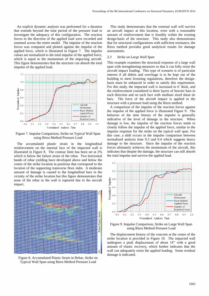
A comparison of the impulse of the reaction forces against
the impulse of the applied force is illustrated Figure 9. The
behavior of the time history of the impulse is generally
indicative of the level of damage in the structure. When
damage is low, the impulse of the reaction forces tends to
closely follow the impulse of the applied force, similar to the
impulse response for the strike on the typical wall span. For
this case, a shift occurs in the impulse comparison between
normalized analysis time 0.3 and 0.4 which suggests heavy
damage to the structure. Since the impulse of the reaction
forces ultimately achieves the momentum of the aircraft, this
indicates that despite the damage, the structure can still absorb
the total impulse and survive the applied load.
Figure 9. Impulse Comparison, Strike on Large Wall Span
using Riera Method Pressure Load
The displacement history of the concrete at the center of the
strike location is provided in Figure 10. The impacted wall
undergoes a peak displacement of about 18” with a good
amount of elastic recovery, which further indicates that the
wall can adequately resist the applied loading. Some residual
damage is indicated.

Proceedings of the 9th International Conference on Structural Dynamics, EURODYN 2014
1994
Figure 10. Concrete Displacement History under Impact,
Strike on Large Wall Span using Riera Method Pressure Load
Figure 11 provides a contour of maximum principal strain in
the concrete for a section cut view through the impacted wall.
Here the contour limit is set at 2% to indicate the areas with
more extensive damage. Large extents of cracking occur on
the outer face of the wall extending beyond the diameter of
the fuselage. More extensive cracking damage propagates
through the thickness of the wall diagonally from the strike
location towards the supporting transverse slabs as the wall
transfers the load to the supports.
Figure 11. Section Cut View of Concrete Cracking Damage,
Strike on Large Wall Span using Riera Method Pressure Load
The accumulated plastic strain in the longitudinal
reinforcement on the internal face of the impacted wall is
illustrated in Figure 12. The contour limit has been set at
1.5% which is below the failure strain of the rebar. This
figure demonstrates that despite the significant rebar yielding
in the longitudinal bars, no bars have ruptured, and the
bending capacity of the wall has not been fully exhausted.
The accumulated plastic strain in the shear tie reinforcement
in the impacted wall is illustrated in Figure 13. The contour
limit has been set at 5% which is equal to the failure strain in
the rebar. This figure shows the extensive rebar yielding in
the tie bars across nearly the entire span of the impacted wall,
with some bars exceeding the failure strain and rupturing.
This also illustrates the high shear forces involved and
provides further evidence that the wall can survive the impact
loading.
Figure 12. Accumulated Plastic Strain in Longitudinal Rebar,
Strike on Large Wall Span using Riera Method Pressure Load
Figure 13. Accumulated Plastic Strain in Shear Tie Rebar,
Strike on Large Wall Span using Riera Method Pressure Load
This example shows that even large span walls can be
configured to fully resist the impact forces if needed. For
these types of configurations, the design-basis must be
enhanced in order to add sufficient resistance. For this
example in particular, the addition of dense tie bars to the
impacted wall is essential to withstand the large shear forces
and maintain the composite action of the R/C wall. The
required design enhancements can only be determined by
analysis, and with some iteration, an optimized structural
configuration can be determined to minimize the added
construction costs. This study also further demonstrates that
the Riera method provides good results when the wall is able
to resist the aircraft impact, even with extensive damage.
3.4 Missile-Target Interaction
For this next example a slightly modified configuration of the
typical wall span is considered to demonstrate a scenario
where the impacted wall fails due to aircraft impact. The
amount of longitudinal reinforcement remains at two layers
but the bar size is reduced. The force of the aircraft impact is
first applied to the structure with a pressure load using the
Riera method and then again with the missile-target
interaction method through the use of an explicitly modeled
aircraft impacting on the structure.
Proceedings of the 9th International Conference on Structural Dynamics, EURODYN 2014
1995
For the analysis using the Riera method pressure load, a
contour of maximum principal strain of the impacted wall at
the time point when the first wall is nearing failure is shown
in Figure 14. A large circular extent of heavy cracking
damage forms on the external face of the wall that is
approximately the size of the fuselage. Additionally, a ring of
elements has reached the failure strain criteria and have been
deleted. The damage pattern clearly demonstrates that the
impacted wall is failing due to punching shear.
Figure 14. Point of Failure, Strike on Under-reinforced
Typical Wall Span using Riera Method Pressure Load
The damage in the concrete at the end of the analysis is
illustrated in Figure 15 to demonstrate the complete failure of
the wall as predicted with the Reira loading method.
Furthermore, the accumulated plastic strain in the longitudinal
bars on the inside face of the wall is illustrated in Figure 16 to
show the extensive rebar rupturing. Although it is difficult to
discern the level of damage beyond the failed wall with the
Riera method, it does demonstrate that the mode of failure of
the wall is captured which is useful for developing design
enhancements.
Figure 15. Residual Damage, Strike on Under-reinforced
Typical Wall Span using Riera Method Pressure Load
Since the Riera method is inadequate for assessing the
consequences of wreckage entering into the building, the
missile-target interaction method must be utilized. For this
particular study, the spent fuel pool sits behind the impacted
wall so it is important to understand the potential for damage
to the pool.
Figure 16. Rebar Failure, Strike on Under-reinforced Typical
Wall Span using Riera Method Pressure Load
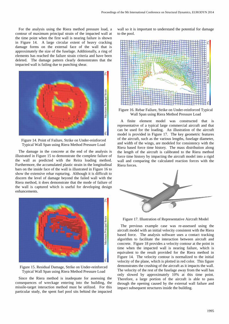
A finite element model was constructed that is
representative of a typical large commercial aircraft and that
can be used for the loading. An illustration of the aircraft
model is provided in Figure 17. The key geometric features
of the aircraft, such as the various lengths, fuselage diameter,
and width of the wings, are modeled for consistency with the
Riera based force time history. The mass distribution along
the length of the aircraft is calibrated to the Riera method
force time history by impacting the aircraft model into a rigid
wall and comparing the calculated reaction forces with the
Riera forces.
Figure 17. Illustration of Representative Aircraft Model
The previous example case was re-assessed using the
aircraft model with an initial velocity consistent with the Riera
based force. The analysis software uses a contact tracking
algorithm to facilitate the interaction between aircraft and
concrete. Figure 18 provides a velocity contour at the point in
time when the impacted wall is nearing failure, which is
equivalent to the result provided for the Riera method in
Figure 14. The velocity contour is normalized to the initial
velocity of the plane, which is plotted in red color. This figure
demonstrates the crushing of the aircraft as it impacts the wall.
The velocity of the rest of the fuselage away from the wall has
only slowed by approximately 10% at this time point.
Therefore, a large portion of the aircraft is able to pass
through the opening caused by the external wall failure and
impact subsequent structures inside the building.

Proceedings of the 9th International Conference on Structural Dynamics, EURODYN 2014
1996
Figure 18. Point of Failure, Strike on Under-reinforced
Typical Wall Span using Missile-Target Interaction Method
A section cut view is illustrated in Figure 19 that shows the
extent of wreckage inside the building by the end of the
analysis. The velocity contour demonstrates that by this time
the momentum of the aircraft is almost entirely stopped with
most of the wreckage crushing up against the subsequent
interior wall. The tail of the aircraft has rotated slightly
upward impinging against the upper portion of the external
wall. The consequences of failure of the exterior wall can be
assessed by considering the subsequent structural response of
the interior walls.
Figure 19. Section Cut View of Wreckage Propagation, Strike
on Under-reinforced Typical Wall Span using Missile-Target
Interaction Method
4 SUMMARY AND CONCLUSIONS
It is becoming the new international standard in nuclear safety
to consider the effects of an impact of a large commercial
aircraft as a beyond-design-basis event through the application
of advanced structural analyses. Performing physical damage
assessments for aircraft impact requires the combination of
robust explicit nonlinear structural dynamics software with
advanced constitutive modeling of reinforced concrete and
realistic, detailed modeling of the structural elements.
A large, three-dimensional finite element model was
developed to provide illustrative examples of various aircraft
impact scenarios. The first case considers a strike on a typical
size wall span and demonstrates that the design-basis
configuration of the external wall is adequate to fully resist
the impact. For other cases where the wall span is large or the
design based reinforcement is inadequate, design
enhancements can be configured for physical protection if
needed. For typical bay sizes, a moderate increase in the
reinforcement is generally sufficient to adequately strengthen
the wall. For very large wall spans, an increase in concrete
thickness and heavier reinforcement, both longitudinal
bending bars and shear tie bars, may be required. Increasing
the concrete strength is also a good way to achieve more
resistance to impact forces.
These studies also demonstrate that the Riera method
provides good analytical results for configurations with
sufficient structural resistance, even with extensive damage.
The Riera method is also a useful approach to determine if a
wall cannot withstand the applied load and identify the failure
mode that limits the strength of the structure. However, if the
actual consequences of structural failure are needed, then the
missile-target interaction method provides a more realistic
assessment.
REFERENCES
[1] “Methodology for Performing Aircraft Impact Assessments for New
Plant Designs,” NEI 07-13, Rev 8, Nuclear Energy Institute, April,
2011.
[2] Guidance for the Assessment of Beyond-Design-Basis Aircraft Impacts,
Draft Regulatory Guide DG-1176, United States Nuclear Regulatory
Commission, Washington, DC, July 2009.
[3] ANACAP-U, Version 2.5, Theory Manual, ANA-QA-145, ANATECH
Corp., San Diego, CA, 1998.
[4] TeraGrande, Version 1.1-121, ANATECH Corp., 2013.
[5] Dunham, R.S., et al., Pretest Prediction of a 1:10 Scale Model Test of
the Sizewell-B Containment Building, ANATECH Report to Sandia
National Labs, Albuquerque, NM, NUREG/CR-5671, 1990.
[6] James, R. J., et al, Seismic Analysis of a Prestressed Concrete
Containment Vessel Model, NUREG/CR-6639, U.S. Nuclear Regulatory
Commission, Washington, August, 1999.
[7] James, R. J., et al, Seismic Analysis of a Reinforced Concrete
Containment Vessel Model, NUREG/CR-6707, U.S. Nuclear Regulatory
Commission, Washington, March, 2001.
[8] James, R. J., Zhang, L., Rashid, Y. R., Impact of High Velocity Objects
into Concrete Structures – Methodology and Application, Proceedings
of 2003 ASME International Mechanical Engineering Congress and
Exposition, Washington, D. C., November 16-21, 2003.
[9] James, R. J. & Rashid, Y. R., Severe Impact Dynamics of Reinforced
Concrete Structures, Proceeding of Sixth European Conference on
Structural Dynamics, Special Session, Paris, France, September 4-7,
2005.
[10] Rashid, Y.R., Ultimate Strength Analysis of Prestressed Concrete
Pressure Vessels, Nuclear Eng. & Design, 7, 1968, pp. 334-344.
[11] Al–Mahaidi, R.S.H., Nonlinear Finite Element Analysis of Reinforced
Concrete Deep Members, Report 79-1, Structural Engineering Dept.
Cornell University, Jan. 1979.
[12] Resistance of Nuclear Power Plant Structures Housing Nuclear Fuel to
Aircraft Crash Impact, Final Report by ANATECH Corp, ABS
Consulting, and ERIN Engineering, Electric Power Research Institute,
Palo Alto, CA, February 2003, Not for Public Release.
[13] James, R. J., Zhang, L., Rashid, Y. R., Aircraft Crash Impact at Nuclear
Power Plants – Validation of Analysis Methodology, ANATECH Report
ANA-03-0639 to Electric Power Research institute, Palo Alto, CA,
January 2004, Not for Public Release.
[14] James, R. J., Zhang, L., Rashid, Y. R., Aircraft Crash Impact at Nuclear
Power Plants – Analyses for Diesel Generator Building, ANATECH
Final Report ANA-04-0643 to Electric Power Research Institute, Palo
Alto, CA, February 2004, Not for Public Release.
[15] James, R. J., Zhang, L., Rashid, Y. R., Aircraft Crash Impact at Nuclear
Power Plants – Analyses for Impact into BWR Spent Fuel Support
Structures, ANATECH Summary Report ANA-05-0683 to Electric
Power Research Institute, Palo Alto, CA, August 2005, Not for Public
Release.