nordic empress documents/5p/cg...engine design wartsila vasa 32 engine specs (2) 6607 bhp, 4860 kw,...
TRANSCRIPT

UNITED STATES COAST GUARD
REPORT OF INVESTIGATION INTO THE CIRCUMSTANCES SURROUNDING
THE FIRE ABOARD ROYAL CARIBBEAN INTERNATIONAL PASSENGER VESSEL
NORDIC EMPRESS
IN THE ATLANTIC OCEAN JUNE 15, 2001
RESULTING IN MAJOR DAMAGE NO LOSS OF LIFE OR INJURY

Table of Contents
Executive Summary 1 Vessel Specifics 1 Main Engineroom 2 Narrative 2 Damage 4 Passenger Comments 5 Halon System 6 Main Engine Fuel Supply 6 Latent Unsafe Condition 7 Wartsila Diesel Technical Bulletin 7 Hex Socket Screws 8 Vibration 8 Conclusions 9

Investigation Into The Circumstances Surrounding The Fire Aboard Royal Caribbean International Passenger Vessel NORDIC EMPRESS June 15, 2001, Resulting In Major Damage, No Loss Of Life Or Injury
Executive Summary At approximately 2036 local time on Friday June 15, 2001, the Royal Caribbean International vessel NORDIC EMPRESS (L8716899) suffered a major engineroom fire while enroute to New York, NY. The casualty occurred one hundred and forty miles from Hamilton, Bermuda. Onboard were 1566 passengers and 650 crewmembers. 1557 persons were US Citizens. The fire caused a loss of propulsion without a loss of electrical power or hotel services. Vessel engineers re-cabled critical main engine auxiliary motors and regained propulsion on two engines serving the starboard propeller shaft. The vessel returned to St. George, Bermuda under its own power. There were no deaths or injuries associated with the event. Repair costs to the damaged engine, wiring and control systems may exceed two million dollars. Impacts to the Bermuda economy is estimated at $100,000 each day the vessel is out of service. Lost wages for crewmembers, passenger reimbursements for travel, canceled cruise and compensatory cruises may exceed five million dollars. Vessel Specifics Place of build Chantiers de l'Atlantique, France Delivery Date June 1990 Registry Monrovia, Liberia Classification Det Norske Veritas Safety Certificates Det Norske Veritas Length 691.6 feet Beam 100.7 feet Draft 23.4 feet Gross Tonnage 48,563 Passenger Capacity 1600 Total Crew 685 Speed 19.5 knots Propulsion System (for each shaft) 2 main engines of different HP driving a
clutched reduction gear and shaft with controllable pitch propeller
Total Shaft Horsepower 22,200 Engine Builder Societe Moteurs Duvant Crepelle-Valenciennes Engine Design Wartsila Vasa 32 Engine Specs (2) 6607 BHP, 4860 KW, V-12, 4 cycle
(2)4405 BHP, 3240 KW, Straight 8, 4 cycle Each 32 cm bore, 750 RPM
The NORDIC EMPRESS employs a multi-national crew. The vessel's officers are from European and Mediterranean countries. Crewmembers stem from countries of Central America, Oceania, Central and South East Asia. The vessel serves two cruise ship markets. From the months of June until late October, the NORDIC EMPRESS sails from New York City on weekly trips to Hamilton and Kings Wharf, Bermuda. During the months of November through May the vessel sails out of San Juan to several destinations throughout the Eastern Caribbean.
2
Main Engineroom The fore and aft bulkheads of the NORDIC EMPRESS's main engineroom form the boundaries of fire zone IV. The deck plating just above the tank tops establishes the 00 level of the engineroom which contains the vessel's main engines and supporting auxiliary equipment. The main engines are numbered one through four starting with number one located on the outboard starboard side. The next platform up within the machinery space establishes the 01 level having an athwartships platform on the forward end and decking on each side and along the rear bulkhead. A center platform offset to the port side connects the forward platform with after athwartships decking. On the port side of the 01 level is the engineroom machine shop while towards the centerline against the forward bulkhead are numerous electrical cabinets. A ladder leads upwards to the 02 level near the engineroom exhaust fan inlets. The 02 level contains piping and valves associated with the auxiliary steam system. Another ladder provides access to the entrance of the fan room on the 03 level. Narrative All systems were operating normally onboard the NORDIC EMPRESS during the evening of Friday, June 15th as it headed to New York on a course of approximately 319 degrees with calm seas and light to variable winds. Two groups of main engines were clutched in and turning two propulsion shafts having controllable pitch propellers. The vessel was making about 17 knots. Engineroom alarm recording equipment indicated that at 2236 local time, the Second Engineer standing watch in the engine controlroom received a fuel oil low-pressure alarm to the number three main engine; one of two engines servicing the port propeller shaft. Because of the low pressure, a standby fuel oil pump automatically came on line to supply fuel and an alarm sounded indicating the automatic startup. Next, the Engineer received a third alarm indicating a fuel oil failure to the engine. Within seconds of this series of alarms the Engineer observed a fire near the port main engines via a closed circuit television. He telephoned the bridge by speed dialing 911 and informed one of the two Deck Officers on watch of a fire in the main engineroom. He then called the vessel's Chief Engineer and Staff Chief Engineer and used an internal beeper system to contact the patrolling Oiler who was making rounds in one of the auxiliary machinery rooms on the 00 level of the vessel. Just prior to the call from the engineroom, the First Officer on the bridge answered an alarm on the Autronica fire detection system indicating a fire in the machinery space. Immediately after the call, the First Officer sounded a "BRAVO, BRAVO, BRAVO Main Engineroom" on the vessel's public announcement system reaching all crew and passenger public spaces and passageways. The phrase "BRAVO BRAVO BRAVO" is understood by the vessel's crew as meaning "FIRE" and used to avoid alerting the passengers. The First Officer also paged other essential personnel and senior officers. The vessel's Staff Captain and persons with emergency responsibilities were on their way to their appropriate stations with the fire team members heading towards the staging area located on the second deck in the crew’s main passageway known as Biscayne Boulevard. Using the computerized Damatic control and monitoring system, the Second Engineer began securing the fuel supply pumps, fuel system quick closing tank valves, and ventilation systems in the main engineroom spaces. The securing of the fuel system caused the starboard main engines to stop, while the destruction of controls and sensors on the port number three engine caused it to stop soon after the fire started. The First Engineer, Chief Engineer Junior and Chief Engineer all arrived in the engineroom at about the same time. The First Engineer and Chief Junior went directly to the auxiliary machinery space just forward of the main engineroom. The Oiler on duty who having been paged only minutes earlier had reeled out a fire hose towards watertight door 007 in the aft section of the machinery space and charged the line. The First Engineer and Chief Junior grabbed the hose and moved to the engineroom entrance at the watertight door. They proceeded to fight the fire that was on the front of the number three main

3
engine from an area just inside the watertight door. They managed to subdue the fire slightly but noticed that it spread towards the transverse 01 platform immediately above and forward of the engines. Shortly afterward the Safety Officer and several of his team members arrived in the engineroom. The firefighters decided to close the watertight doors and activate the Flexi-fog water sprinkler system. Doors 007 on the lowest level and 117 located on the port side bulkhead 01 level of the main engineroom were closed. Six minutes after the discovery of the fire the Flexi-fog system was activated from the engine controlroom over both sets of engines, port and starboard. A fine mist of extinguishing water was released via three rotating nozzles located inline and immediately above each engine. During those initial minutes, the Master took control of the vessel and command on the bridge. A "SECURITE, SECURITE, SECURITE" message was broadcast on VHF channel 16. Onboard the vessel, the emergency signal was sounded on the ship's whistle and general alarm. Using the public announcement system, the Captain directed the passengers to their cabins to retrieve their life jackets and proceed to their muster stations. Not under command signals were displayed. The Chief Officer organized a crew to check and evacuate the crew deck number one cabin area. At about the same time, the Hotel Director reported to her office and obtained for distribution her zone leader sheets. These sheets detail the exact emergency location of each crewmember within each zone. Zone leaders, who are typically headwaiters, then circulate throughout their zone ensuring that respective crewmembers are in their designated place answering questions, assisting and directing the flow of passengers as they exit public spaces heading to their cabins to retrieve their life jackets and then return to their assigned muster stations. Simultaneously, the cabin attendants for each section check each room verifying that lifejackets have been retrieved. Order and direction at the muster stations is maintained by lifeboat commanders who are all Ship’s Officers. Once the passengers are their muster stations the zone leaders recheck and evacuate each zone. The Flexi-fog system operated for about fifteen minutes and shortly afterward several firefighters checked the fire via the watertight doors and report that it was extinguished. One fire group was directed to perform boundary cooling around the machinery space. Other fire groups cooled the port and starboard bunker stations and the port tender boarding areas. The Chief Mate and his team continued the evacuation of deck two crew cabin and service spaces. Twenty-four minutes after the first use of Flexi-fog system, a flashback occured over the number three main engine. It was immediately extinguished by one of the firefighting crews near the area. Seventeen minutes later heat was reported in the machine shop and a team entered for inspection and cooling. During the next hour and twenty-two minutes different teams entered the engineroom for inspection purposes. On the last entry, it was noticed that electrical cables were burning near the overhead above the 01 level forward main engineroom athwartships platform. The engineroom is evacuated and watertight doors closed. Next the Halon system was activated releasing 885 kilograms from thirteen cylinders positioned at various locations on the 00 and 01 levels. Minutes later, the Flexi-fog system was restarted. Nineteen minutes later the engineroom was reentered again by two teams. It is now about 0112 on Saturday the 16th of June, nearly two and one half hours have passed since the initial report of fire. At 0138 the cable fire was logged as being extinguished. Various inspections and boundary area coolings continued until about 0230. Fire guards and equipment are finally ordered to stand down at about 0330. While the firefighting and boundary cooling was taking place, the passengers remained at their muster stations. They were continuously apprised of the situation via the public announcement system and were served refreshments, but no alcohol, from a rolling cart. Shortly after midnight the passengers were allowed to go inside to the public lounges located on the boat deck. At approximately 0220 the passengers and crew were permitted to return to their cabins.
4
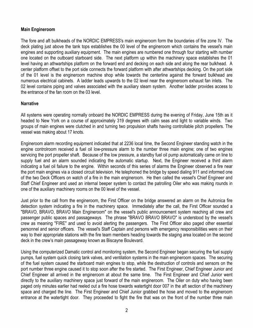
Damage Nearly all of the damage caused by the fire occurred in the main machinery space and fan room in zone four of the vessel on the 00, 01, 02 and 03 levels except for some blistered paint observed near the port tender vessel station boarding area. The fire originated on the forward end of the number three main engine serving the port propeller shaft and caused significant damage to automation controls, remote sensing equipment, pyrometer cabling, pneumatic tubing, auxiliary pumps and controlled devices. The inboard forward end of the number four engine was damaged similarly. Approximately two meters away in front of the engines on the same level were electrical control panels for the pair of engines. On their doors were mounted various indicating lamps, meters and switches which were all destroyed while components inside were virtually unaffected. Near the same area in the overhead were numerous pipes that sustained limited insulation and lagging damage. One deck up on the 01 level in the main engineroom, forward side, is an athwartships platform that is about two meters wide for the width of the compartment. The aft edge of the platform does not overhang the area above the engine fronts. Along the centerline of the overhead above the platform runs a cableway for its entire length. The cableway contains hundreds of conductors serving various motors and controls for fans and pumps, valve actuators, ventilation, automation controls, remote indication systems and lighting circuits for the machinery, controls and equipment in the main engine machinery space. All of this wiring was destroyed, their insulation and shielding completely disintegrated revealing bare conductors. Also damaged in this area was an eleven-section electrical control panel situated against the forward bulkhead containing the operating controllers for the machinery within the space. It suffered significant damage externally and limited damage internally.
5
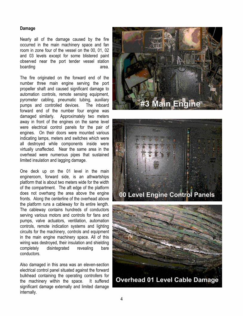
Generally all lighting, annunciating and visible alarms, shields and lense covers were destroyed on this level (01) and the next upper level in this space (02). The paint on various equipment, structures, and pipe lagging or coverings was damaged on the upper levels. Two large intake plenums above the port main engines were warped because of the fire. In the same general area and damaged after closing were actuating cylinders that operated the inlet dampers for exhaust fans of this space. Structural damage appeared to be limited to a few slightly distorted stiffeners located on the forward bulkhead, port side, between the 02 and 03 levels. The stiffeners associated with the deck on the 03 level were also distorted and the deck plating at the forward end of the fan room was warped and bowed. However, none of the deflection affected machinery or its associated mounting arrangements within the fan room. The only other damage present in this area was the overheating of paint on the port supply fan discharge casing which resulted from the conduction and convection of heat from the intake plenums located above the port main engines. Passenger Comments The vessel returned to Bermuda late in the evening on Saturday, the 16th of June. The remaining voyage was cancelled and by Sunday morning most passengers disembarked for flights to the US. About thirty-five passengers remained onboard throughout the day having been booked on other cruise ships for transfer back to the states. Informal conversations with numerous passengers revealed extensive satisfaction with the manner in which the casualty was handled. The passengers had nothing but praise for the officers and crew of the vessel. They were kept constantly apprised of the situation and indicated that the confident and professional manner in which the officers and crew performed their emergency duties resulted in the orderly and controlled management of the passengers.

6
Halon System During post casualty inspections of equipment and safety systems it was discovered that the Halon gas supply for the purifier room was depleted some time before the fire. The purifier room is located on the same level (00) of the main engines but in a different compartment. The room contains numerous centrifuges and heating equipment for the management of fuel supplied to the main engines and generators. Senior officers where unaware of this latent unsafe condition and unable to explain when or why the release occurred. Main Engine Fuel Supply All of the main engines of the NORDIC EMPRESS were of Wartsila design. The engine that caught fire is a 6607 BHP, V arranged, 12 cylinder, 750 rpm, four stroke cycle engine. Each cylinder has a respective fuel pump and injector. The fuel pumps on each bank of the engine are connected by jumpers to common fuel oil supply and return manifolds. The fuel pumps, their associated racks and supply and return manifolds were all enclosed in a casing identified as the "hotbox." A hotbox was located on each side of the engine. The fuel supplied to the engine is an intermediate fuel oil. It is typically heated to near 130 C and supplied under pressure between seven and nine bars. The fuel supply and return piping on the number three main engine rose above the deckplates on the forward inboard side though a flexible connection. The piping came up the engine toward the forward end of the inboard hotbox and contained several sets of flanges, bends and turns as it ran across the engine front to supply the outboard hotbox of the engine. Two sets of thirty-four millimeter diameter piping, vertically inline with one another were welded to a bracket which formed one half of a flanged connection. From that flange, two additional lengths of piping about sixty centimeters in length with some slight bends finalized the connection to the inboard side fuel supply and return manifolds located within the hotbox. After the casualty, an inspection revealed that three of the four socket type hex screws attaching the fuel supply piping of the lower fuel line from the outboard manifold within the hotbox to the bracketed flange assembly had failed at the flange.
7
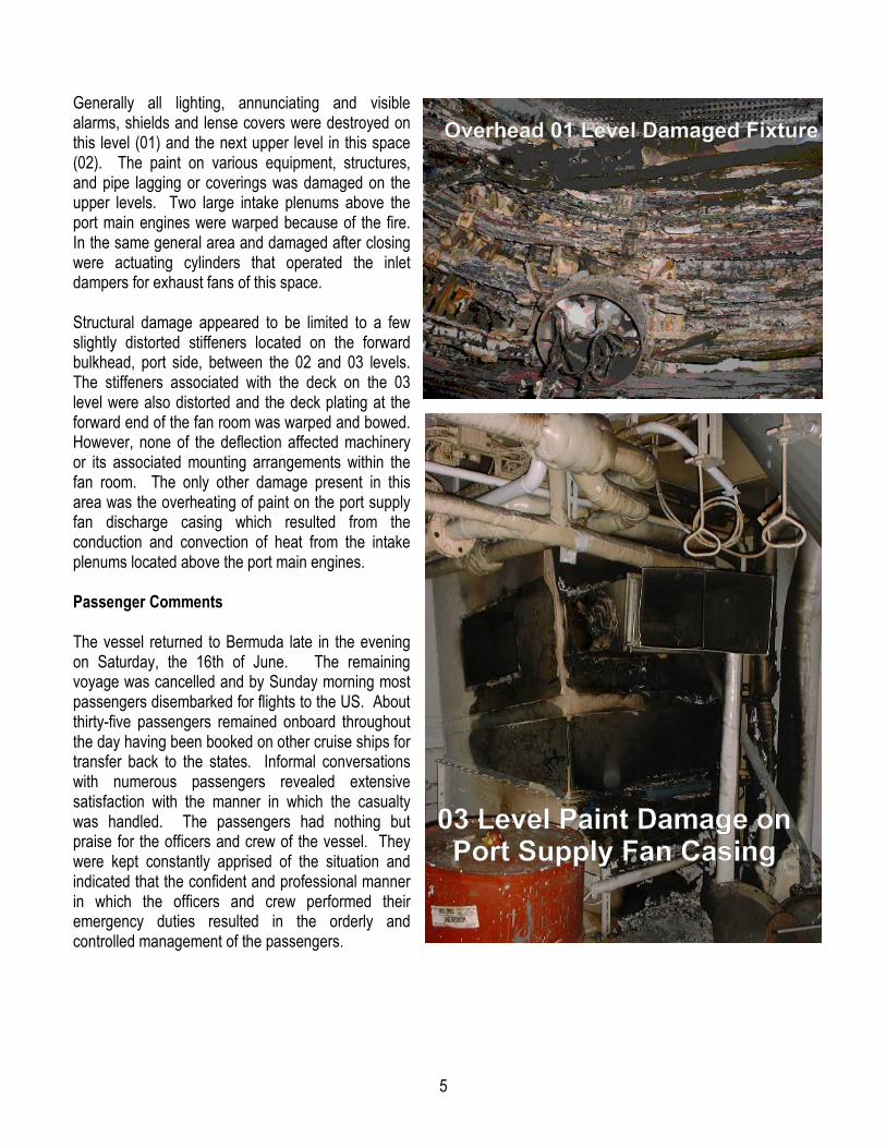
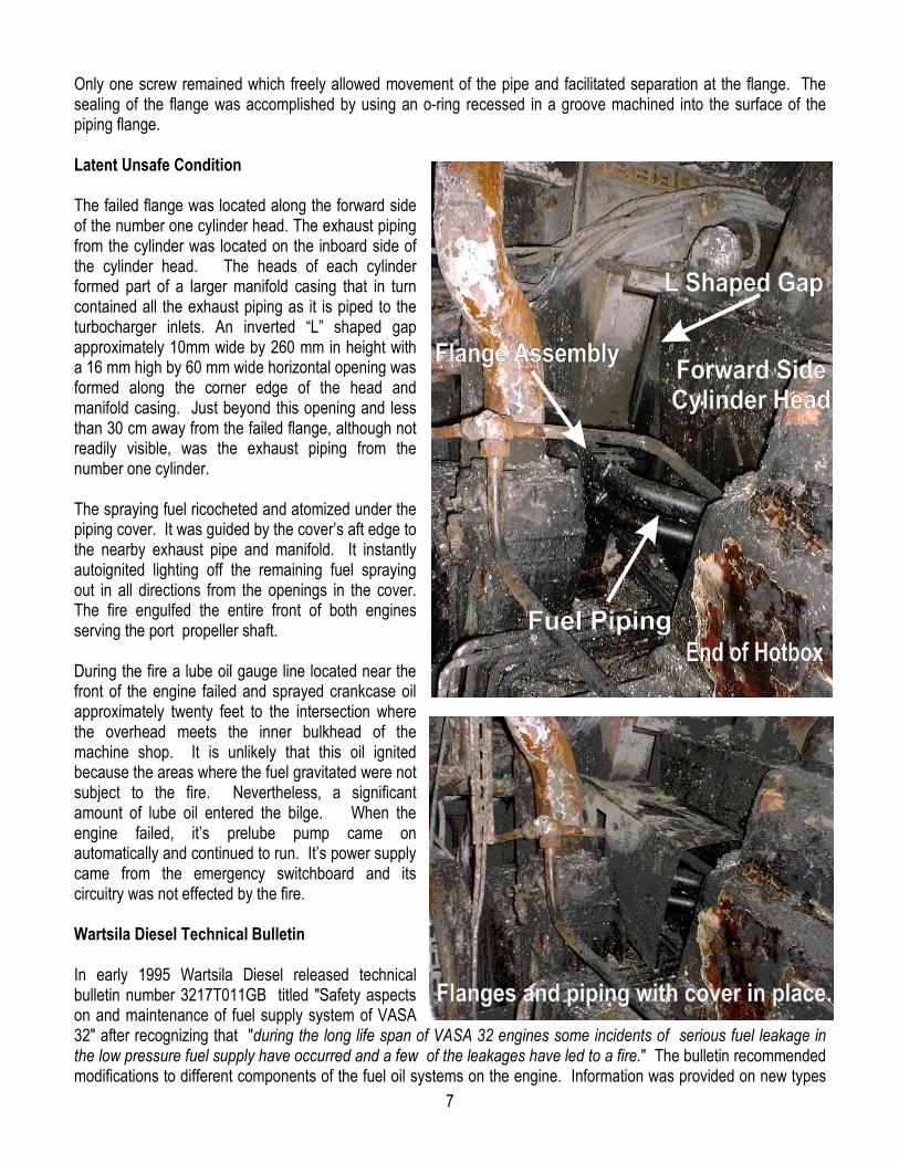
Only one screw remained which freely allowed movement of the pipe and facilitated separation at the flange. The sealing of the flange was accomplished by using an o-ring recessed in a groove machined into the surface of the piping flange. Latent Unsafe Condition The failed flange was located along the forward side of the number one cylinder head. The exhaust piping from the cylinder was located on the inboard side of the cylinder head. The heads of each cylinder formed part of a larger manifold casing that in turn contained all the exhaust piping as it is piped to the turbocharger inlets. An inverted “L” shaped gap approximately 10mm wide by 260 mm in height with a 16 mm high by 60 mm wide horizontal opening was formed along the corner edge of the head and manifold casing. Just beyond this opening and less than 30 cm away from the failed flange, although not readily visible, was the exhaust piping from the number one cylinder. The spraying fuel ricocheted and atomized under the piping cover. It was guided by the cover’s aft edge to the nearby exhaust pipe and manifold. It instantly autoignited lighting off the remaining fuel spraying out in all directions from the openings in the cover. The fire engulfed the entire front of both engines serving the port propeller shaft. During the fire a lube oil gauge line located near the front of the engine failed and sprayed crankcase oil approximately twenty feet to the intersection where the overhead meets the inner bulkhead of the machine shop. It is unlikely that this oil ignited because the areas where the fuel gravitated were not subject to the fire. Nevertheless, a significant amount of lube oil entered the bilge. When the engine failed, it’s prelube pump came on automatically and continued to run. It’s power supply came from the emergency switchboard and its circuitry was not effected by the fire. Wartsila Diesel Technical Bulletin In early 1995 Wartsila Diesel released technical bulletin number 3217T011GB titled "Safety aspects on and maintenance of fuel supply system of VASA 32" after recognizing that "during the long life span of VASA 32 engines some incidents of serious fuel leakage in the low pressure fuel supply have occurred and a few of the leakages have led to a fire." The bulletin recommended modifications to different components of the fuel oil systems on the engine. Information was provided on new types

8
of brackets, piping jumpers to and from injection pumps as well as modifications to the fuel-piping crossover from the side banks of the engines. One of the most significant changes to the system was the conversion of the fuel supply piping from a two screw system to a four screw system. Vessel engineers reported that the crossover piping on the NORDIC EMPRESS was converted in early 1999 by Wartsila representatives. The bulletin also recommended that after 2000 running hours an inspection of the fuel supply system should be made to systematically ensure that all screws are in place and to determine that they have not loosened. Hex Socket Screws The technical bulletin provides a parts list for the rebuilding of the fuel pipes between both banks of the engine. The screws recommended for the system are hex socket screws M8 by 30 mm, quality 8.8 with a material standard meeting ISO 898/1. Two of the fractured screws recovered were 23 mm and 36 mm in length. The screws were also of different quality. Different qualities necessitated different torque requirements. Tightening too close or beyond the screw's yield strength may result in failure or torque loss, while tightening to a lower range of the yield may result in insufficient preload for sealing and insufficient residual load to maintain the seal. The fuel line flange was designed for screws 30 mm long yet after the casualty a much longer screw requiring spacers was found. Additionally other improperly sized screws were observed on flanges of the number three main engine crossover piping. Vibration Wartsila Diesel indicates that fuel pipes to and from injection pumps are principally affected by pressure pulses developed by the fuel injection pumps, vibrations initiated by normal engine vibrations, and static stress caused by heat expansion. Information from Screw Science Limited, an internationally recognized leader in screwed joint technology states the following - "It is widely believed that vibration causes screw loosening. By far the most frequent cause of loosening is side sliding of the nut or screw head relative to the joint, resulting in relative motion occurring in the threads. If this does not occur, then the screws will not loosen, even if the joint is subjected to severe vibration. Pre-loaded screws (or nuts) rotate loose, as soon as relative motion between the male and female threads takes place. This motion cancels the friction grip and originates an off torque which is proportional to the thread pitch and to the preload. The off torque rotates the screw loose, if the friction under the nut or screw head bearing surface is overcome, by this torque. " The flange screws securing the fuel supply flange were subject to vibrational loosening. The general loosening of the flange and vibration within the assembly may have caused additional stresses resulting in fatigue and failure. The screws most likely failed at different times. The longest screw found showed evidence of frictional wear, located just before the break, indicating that it was loose long before it failed. One screw was missing, possibly having loosened and fallen off the engine at a much earlier time. When the last screw fractured, the hydraulic action of the fuel within the piping at the flange caused it to separate releasing fuel and ejecting a segment of the o-ring seal.

9
Conclusions
1. Without scientific metallurgical analysis it is impossible to identify the exact manner in which the fuel line flange screws failed. The post fire inspection revealed that the components of the failed flange assembly did not comply with arrangements outlined in the 1995 technical bulletin.
2. Different size screws with different qualities were used. The use of different screws would have demanded more specific and varying tightening procedures thus increasing the likelihood of improper installation.
3. The 1995 Wartsila Technical Bulletin does not indicate that a torque wrench be applied to each fastener during the 2000 hour inspection. A visual inspection is inadequate in determining the tightness of various connections or torque values associated with the screws.
4. There were no defenses minimizing the effect of the fuel release or preventing it from reaching an ignition source. The fuel ricocheted and atomized under the cover and instantly contacted the high temperature surface of the number one cylinder exhaust pipe. The fuel was heated to its autoignition temperature, combusted and the fire propagated in the immediate area near the front of both engines.
5. The initial actions of Deck and Engineering Officers and associated Ratings on the bridge and within the engineroom are critical during the first stages of an emergency or engineering casualty. Proper decisions and actions in accordance with good maritime practice were taken by these crewmembers.
6. During the emergency the Master, Officers and Crew of NORDIC EMPRESS managed the passengers exceptionally well. The mustering process took place without injury in an orderly and controlled manner.
7. Due to the weather, sea conditions and the professional management of the passengers by the crew at the time casualty, it is likely that lifeboats and liferafts could have been launched and boarded safely if needed.
8. The safety and emergency policies and procedures with respect to passenger and crew egress onboard the NORDIC EMPRESS appear to be implemented and practiced effectively.
9. The firefighting and boundary cooling procedures performed during the casualty were generally appropriate and effective in containing and extinguishing the fire within the main engineroom. Better inspection of the cabling on the 01 platform after the initial extinguishment may have enabled the firefighters to take earlier corrective action instead of having to release the Halon system and restart the Flexi-fog system.
10. The segment of the Flexi-fog extinguishing system installed over the main engines performed well. The system may have provided more comprehensive cooling of the machinery space and possibly minimized damages if additional nozzles were installed in other areas of the main engineroom.
10
11. The vessel's Halon system servicing the main engineroom operated as designed and contributed to extinguishing the cable fire. However, due to the absence of Halon available in the purifier room the ability to fight a fire in that space was significantly reduced.
Ken Olsen Office of Investigations and Analysis USCG Headquarters Washington, DC