nortel ethernet routing switch 5500 series configuration
TRANSCRIPT
Nortel Ethernet Routing Switch 5500 Series
Configuration-IP RoutingProtocols
NN47200-503 (217465-C).
Document status: StandardDocument version: 03.01Document date: 27 August 2007
Copyright © 2005-2007, Nortel NetworksAll Rights Reserved.
The information in this document is subject to change without notice. The statements, configurations, technicaldata, and recommendations in this document a re believed to be accurate and reliable, but are presented withoutexpress or implied warranty. Users must take full responsibility for their applications of any products specified in thisdocument. The information in this document is proprietary to Nortel Networks .
The software described in this document is furnished under a license agreement and may be used only in accordancewith the terms of that license. The software license agreement is included in this document.
Restricted rights legendUse, duplication, or disclosure by the United States Government is subject to restrictions as set forth in subparagraph(c)(1)(ii) of the Rights in Technical Data and Computer Software clause at DFARS 252.227-7013.
Notwithstanding any other license agreement that may pertain to, or accompany the delivery of, this computersoftware, the rights of the United States Government regarding its use, reproduction, and disclosure are as set forthin the Commercial Computer Software-Restricted Rights clause at FAR 52.227-19.
Statement of conditionsIn the interest of improving internal design, operational function, and/or reliability, Nortel Networks reserves the rightto make changes to the products described in this document without notice.
Nortel Networks does not assume any liability that may occur due to the use or application of the product(s) orcircuit layout(s) described herein.
Nortel Networks software license agreementThis Software License Agreement ("License Agreement") is between you, the end user ("Customer") and NortelNetworks Corporation and its subsidiaries and affiliates ("Nortel Networks"). PLEASE READ THE FOLLOWINGCAREFULLY. YOU MUST ACCEPT THESE LICENSE TERMS IN ORDER TO DOWNLOAD AND/OR USE THESOFTWARE. USE OF THE SOFTWARE CONSTITUTES YOUR ACCEPTANCE OF THIS LICENSE AGREEMENT.If you do not accept these terms and conditions, return the Software, unused and in the original shipping container,within 30 days of purchase to obtain a credit for the full purchase price.
"Software" is owned or licensed by Nortel Networks, its parent or one of its subsidiaries or affiliates, and iscopyrighted and licensed, not sold. Software consists of machine-readable instructions, its components, data,audio-visual content (such as images, text, recordings or pictures) and related licensed materials including all wholeor partial copies. Nortel Networks grants you a license to use the Software only in the country where you acquired theSoftware. You obtain no rights other than those granted to you under this License Agreement. You are responsible forthe selection of the Software and for the installation of, use of, and results obtained from the Software.
1. Licensed Use of Software. Nortel Networks grants Customer a nonexclusive license to use a copy of theSoftware on only one machine at any one time or to the extent of the activation or authorized usage level, whicheveris applicable. To the extent Software is furnished for use with designated hardware or Customer furnished equipment("CFE"), Customer is granted a nonexclusive license to use Software only on such hardware or CFE, as applicable.Software contains trade secrets and Customer agrees to treat Software as confidential information using the samecare and discretion Customer uses with its own similar information that it does not wish to disclose, publish ordisseminate. Customer will ensure that anyone who uses the Software does so only in compliance with the terms ofthis Agreement. Customer shall not a) use, copy, modify, transfer or distribute the Software except as expresslyauthorized; b) reverse assemble, reverse compile, reverse engineer or otherwise translate the Software; c) createderivative works or modifications unless expressly authorized; or d) sublicense, rent or lease the Software. Licensorsof intellectual property to Nortel Networks are beneficiaries of this provision. Upon termination or breach of thelicense by Customer or in the event designated hardware or CFE is no longer in use, Customer will promptly returnthe Software to Nortel Networks or certify its destruction. Nortel Networks may audit by remote polling or other
reasonable means to determine Customer’s Software activation or usage levels. If suppliers of third party softwareincluded in Software require Nortel Networks to include additional or different terms, Customer agrees to abide bysuch terms provided by Nortel Networks with respect to such third party software.
2. Warranty. Except as may be otherwise expressly agreed to in writing between Nortel Networks and Customer,Software is provided "AS IS" without any warranties (conditions) of any kind. NORTEL NETWORKS DISCLAIMSALL WARRANTIES (CONDITIONS) FOR THE SOFTWARE, EITHER EXPRESS OR IMPLIED, INCLUDING, BUTNOT LIMITED TO THE IMPLIED WARRANTIES OF MERCHANTABILITY AND FITNESS FOR A PARTICULARPURPOSE AND ANY WARRANTY OF NON-INFRINGEMENT. Nortel Networks is not obligated to provide support ofany kind for the Software. Some jurisdictions do not allow exclusion of implied warranties, and, in such event, theabove exclusions may not apply.
3. Limitation of Remedies. IN NO EVENT SHALL NORTEL NETWORKS OR ITS AGENTS OR SUPPLIERS BELIABLE FOR ANY OF THE FOLLOWING: a) DAMAGES BASED ON ANY THIRD PARTY CLAIM; b) LOSS OF, ORDAMAGE TO, CUSTOMER’S RECORDS, FILES OR DATA; OR c) DIRECT, INDIRECT, SPECIAL, INCIDENTAL,PUNITIVE, OR CONSEQUENTIAL DAMAGES (INCLUDING LOST PROFITS OR SAVINGS), WHETHER INCONTRACT, TORT OR OTHERWISE (INCLUDING NEGLIGENCE) ARISING OUT OF YOUR USE OF THESOFTWARE, EVEN IF NORTEL NETWORKS, ITS AGENTS OR SUPPLIERS HAVE BEEN ADVISED OF THEIRPOSSIBILITY. The forgoing limitations of remedies also apply to any developer and/or supplier of the Software. Suchdeveloper and/or supplier is an intended beneficiary of this Section. Some jurisdictions do not allow these limitationsor exclusions and, in such event, they may not apply.
4. General
a) If Customer is the United States Government, the following paragraph shall apply: All Nortel Networks Softwareavailable under this License Agreement is commercial computer software and commercial computer softwaredocumentation and, in the event Software is licensed for or on behalf of the United States Government, the respectiverights to the software and software documentation are governed by Nortel Networks standard commercial licensein accordance with U.S. Federal Regulations at 48 C.F.R. Sections 12.212 (for non-DoD entities) and 48 C.F.R.227.7202 (for DoD entities).
b) Customer may terminate the license at any time. Nortel Networks may terminate the license if Customer fails tocomply with the terms and conditions of this license. In either event, upon termination, Customer must either returnthe Software to Nortel Networks or certify its destruction.
c) Customer is responsible for payment of any taxes, including personal property taxes, resulting from Customer’suse of the Software. Customer agrees to comply with all applicable laws including all applicable export and importlaws and regulations.
d) Neither party may bring an action, regardless of form, more than two years after the cause of the action arose.
e) The terms and conditions of this License Agreement form the complete and exclusive agreement betweenCustomer and Nortel Networks.
f) This License Agreement is governed by the laws of the country in which Customer acquires the Software. Ifthe Software is acquired in the United States, then this License Agreement is governed by the laws of the stateof New York.

5
Revision History
Date Revised Version Reason for revision
July 2005 1.00 New document for Software Release 4.2.
July 2006 2.00 Document updated for Software Release 5.0.
August 2007 3.01 updated for Software Release 5.1
Nortel Ethernet Routing Switch 5500 SeriesConfiguration-IP Routing ProtocolsNN47200-503 03.01 Standard
5.1 27 August 2007Copyright © 2005-2007, Nortel Networks
.

6 Revision History
Nortel Ethernet Routing Switch 5500 SeriesConfiguration-IP Routing ProtocolsNN47200-503 03.01 Standard
5.1 27 August 2007Copyright © 2005-2007, Nortel Networks
.
7
Contents
Preface 9Nortel Ethernet Routing Switch 5500 Series 9Related publications 10Finding the latest updates on the Nortel web site 11How to get help 12
An Introduction to IP Routing Protocols 13IP routing 13
IP addressing 13IP routing using VLANs 16Brouter port 19Management VLAN 20Setting IP routing 20Address Resolution Protocol (ARP) 21Static routes 22Non-local static routes 23Routing Information Protocol (RIP) 23Open Shortest Path First (OSPF) protocol 27Route policies 35Virtual Router Redundancy Protocol (VRRP) 37Equal Cost MultiPath (ECMP) 38UDP broadcast forwarding 38Dynamic Host Configuration Protocol (DHCP) / Bootstrap Protocol (BootP) 39Avoiding duplicate IP addresses 44IP blocking 45
IGMP snooping 46IGMP snooping configuration rules 49
IP Routing Configuration and Management 51IP routing initial configuration 51
Global IP routing configuration 51Open Shortest Path First (OSPF) initial configuration 52
IP routing configuration using the CLI 55IP configuration commands 55Layer 3 routable VLANs 56
Nortel Ethernet Routing Switch 5500 SeriesConfiguration-IP Routing ProtocolsNN47200-503 03.01 Standard
5.1 27 August 2007Copyright © 2005-2007, Nortel Networks
.
8 Contents
Static route commands 59Address Resolution Protocol (ARP) commands 64Proxy ARP commands 66Routing Information Protocol (RIP) commands 67Open Shortest Path First (OSPF) commands 82Route policy commands 101Virtual Router Redundancy Protocol (VRRP) commands 104Equal Cost MultiPath (ECMP) commands 110Brouter port commands 112UDP broadcast forwarding commands 113DHCP relay commands 115
IP routing configuration examples 120Address Resolution Protocol (ARP) configuration 120Routing Information Protocol (RIP) configuration 122Open Shortest Path First (OSPF) configuration 134Virtual Router Redundancy Protocol (VRRP) configuration 190Equal Cost Multipath (ECMP) 204
IP routing configuration using the Java Device Manager 206Layer 3 routable VLANs 206IP routing 209Routing Information Protocol (RIP) configuration 222Open Shortest Path First (OSPF) configuration 228Route policies 264Virtual Router Redundancy Protocol (VRRP) 277Equal Cost MultiPath (ECMP) 284Brouter port 285UDP broadcast forwarding 288UDP broadcast interface deletion 295DHCP configuration 295
Configuring IGMP snooping using the Java Device Manager 305
Configuring IGMP using Web-based management 309Configuring IGMP using the Web-based Management Interface 309Displaying multicast membership using the Web-based Management Interface 312
Index 314
Nortel Ethernet Routing Switch 5500 SeriesConfiguration-IP Routing ProtocolsNN47200-503 03.01 Standard
5.1 27 August 2007Copyright © 2005-2007, Nortel Networks
.
9
Preface
This document provides information and instructions on the configurationof IP Routing on the 5500 Series Nortel Ethernet Routing Switch. Consultany documentation included with the switch and the product release notes(see "Related publications" (page 10)) for any errata before beginning theconfiguration process.
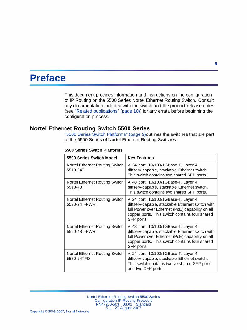
Nortel Ethernet Routing Switch 5500 Series"5500 Series Switch Platforms" (page 9)outlines the switches that are partof the 5500 Series of Nortel Ethernet Routing Switches
5500 Series Switch Platforms
5500 Series Switch Model Key Features
Nortel Ethernet Routing Switch5510-24T
A 24 port, 10/100/1GBase-T, Layer 4,diffserv-capable, stackable Ethernet switch.This switch contains two shared SFP ports.
Nortel Ethernet Routing Switch5510-48T
A 48 port, 10/100/1GBase-T, Layer 4,diffserv-capable, stackable Ethernet switch.This switch contains two shared SFP ports.
Nortel Ethernet Routing Switch5520-24T-PWR
A 24 port, 10/100/1GBase-T, Layer 4,diffserv-capable, stackable Ethernet switch withfull Power over Ethernet (PoE) capability on allcopper ports. This switch contains four sharedSFP ports.
Nortel Ethernet Routing Switch5520-48T-PWR
A 48 port, 10/100/1GBase-T, Layer 4,diffserv-capable, stackable Ethernet switch withfull Power over Ethernet (PoE) capability on allcopper ports. This switch contains four sharedSFP ports.
Nortel Ethernet Routing Switch5530-24TFD
A 24 port, 10/100/1GBase-T, Layer 4,diffserv-capable, stackable Ethernet switch.This switch contains twelve shared SFP portsand two XFP ports.
Nortel Ethernet Routing Switch 5500 SeriesConfiguration-IP Routing ProtocolsNN47200-503 03.01 Standard
5.1 27 August 2007Copyright © 2005-2007, Nortel Networks
.
10 Preface
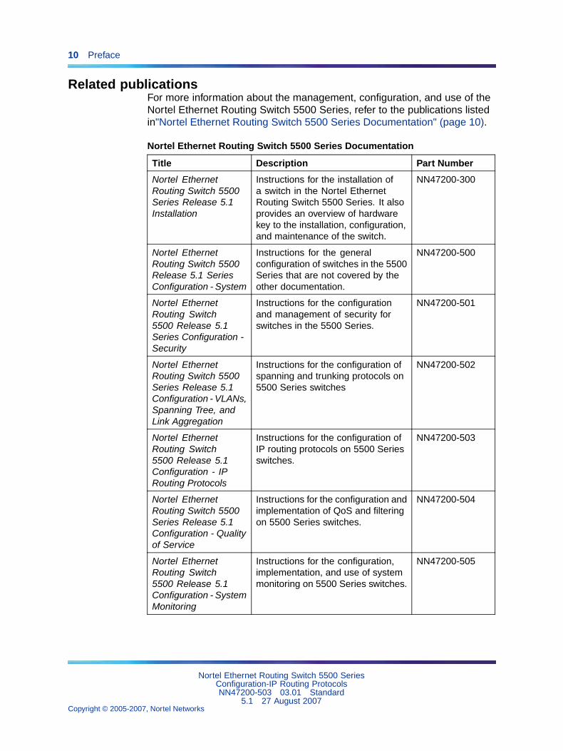
Related publicationsFor more information about the management, configuration, and use of theNortel Ethernet Routing Switch 5500 Series, refer to the publications listedin"Nortel Ethernet Routing Switch 5500 Series Documentation" (page 10).
Nortel Ethernet Routing Switch 5500 Series Documentation
Title Description Part Number
Nortel EthernetRouting Switch 5500Series Release 5.1Installation
Instructions for the installation ofa switch in the Nortel EthernetRouting Switch 5500 Series. It alsoprovides an overview of hardwarekey to the installation, configuration,and maintenance of the switch.
NN47200-300
Nortel EthernetRouting Switch 5500Release 5.1 SeriesConfiguration - System
Instructions for the generalconfiguration of switches in the 5500Series that are not covered by theother documentation.
NN47200-500
Nortel EthernetRouting Switch5500 Release 5.1Series Configuration -Security
Instructions for the configurationand management of security forswitches in the 5500 Series.
NN47200-501
Nortel EthernetRouting Switch 5500Series Release 5.1Configuration - VLANs,Spanning Tree, andLink Aggregation
Instructions for the configuration ofspanning and trunking protocols on5500 Series switches
NN47200-502
Nortel EthernetRouting Switch5500 Release 5.1Configuration - IPRouting Protocols
Instructions for the configuration ofIP routing protocols on 5500 Seriesswitches.
NN47200-503
Nortel EthernetRouting Switch 5500Series Release 5.1Configuration - Qualityof Service
Instructions for the configuration andimplementation of QoS and filteringon 5500 Series switches.
NN47200-504
Nortel EthernetRouting Switch5500 Release 5.1Configuration - SystemMonitoring
Instructions for the configuration,implementation, and use of systemmonitoring on 5500 Series switches.
NN47200-505
Nortel Ethernet Routing Switch 5500 SeriesConfiguration-IP Routing ProtocolsNN47200-503 03.01 Standard
5.1 27 August 2007Copyright © 2005-2007, Nortel Networks
.
Finding the latest updates on the Nortel web site 11
Title Description Part Number
Nortel EthernetRouting Switch 5500Series Release Notes- Release 5.1
Provides an overview of newfeatures, fixes, and limitations ofthe 5500 Series switches. Alsoincluded are any supplementarydocumentation and documenterrata.
NN47200-400
Installing the NortelEthernet RedundantPower Supply 15
Instructions for the installation anduse of the Nortel Ethernet RPS 15.
217070-A
DC-DC ConverterModule for theBaystack 5000 SeriesSwitch
Instructions for the installation anduse of the DC-DC power converter.
215081-A
Nortel EthernetRouting Switch 5500Series Release 5.1Installation - SFP
Instructions for the installation anduse of SFP transceivers.
NN47200-302
You can access technical documentation online at the Nortel TechnicalSupport web site, located at http://www.nortel.com/support. Use thefollowing procedure to access documents on the Technical Support web site:
• If it is not already selected, click the Browse product support tab.
• From the list provided in the product family box, select Nortel EthernetRouting Switch.
• From the product list, select the desired 5500 Series Switch.
• From the content list, select Documentation.
• Click Go.
You can view documents online, download them for future reference, orprinted them. All documents available on the Technical Support web site arein Adobe Portable Document Format (PDF) format.
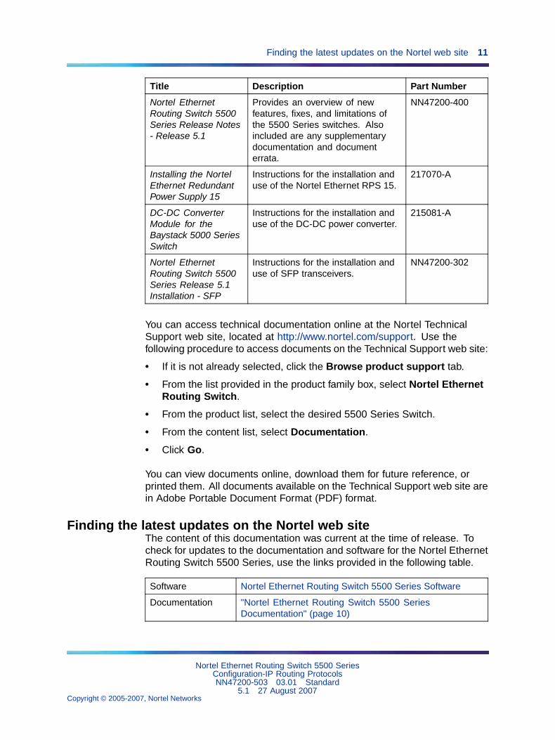
Finding the latest updates on the Nortel web siteThe content of this documentation was current at the time of release. Tocheck for updates to the documentation and software for the Nortel EthernetRouting Switch 5500 Series, use the links provided in the following table.
Software Nortel Ethernet Routing Switch 5500 Series Software
Documentation "Nortel Ethernet Routing Switch 5500 SeriesDocumentation" (page 10)
Nortel Ethernet Routing Switch 5500 SeriesConfiguration-IP Routing ProtocolsNN47200-503 03.01 Standard
5.1 27 August 2007Copyright © 2005-2007, Nortel Networks
.
12 Preface
How to get helpIf a service contract for the Nortel product has been purchased from adistributor or authorized reseller, contact the technical support staff for thatdistributor or reseller for assistance.
If a Nortel service program was purchased, contact Nortel TechnicalSupport.
The following information is available online:
• contact information for Nortel Technical Support
• information about the Nortel Technical Solutions Centers
• information about the Express Routing Code (ERC) for your product
An ERC is available for many Nortel products and services. When an ERCis used, the call is routed to technical support personnel who specializein supporting the service or product. The ERC for a particular product orservice is available online.
The main Nortel support portal is available at http://www.nortel.com/support.
Nortel Ethernet Routing Switch 5500 SeriesConfiguration-IP Routing ProtocolsNN47200-503 03.01 Standard
5.1 27 August 2007Copyright © 2005-2007, Nortel Networks
.
13
An Introduction to IP Routing Protocols
This chapter provides an introduction to IP routing and IP routing protocolsused in the Nortel Ethernet Routing Switch 5500 Series. Subsequentchapters will provide a more detailed description of switch capabilities andconfiguration procedures.
IP routingTo configure IP routing on the Nortel Ethernet Routing Switch 5500 Series,use virtual local area networks (VLAN) to create virtual router interfaces byassigning an IP address to the VLAN. This section discusses this conceptin depth.
For a more detailed description about VLANs and their use, consult NortelEthernet Routing Switch 5500 Series Release 5.1 Configuration - VLANs,Spanning Tree, and Link Aggregation.
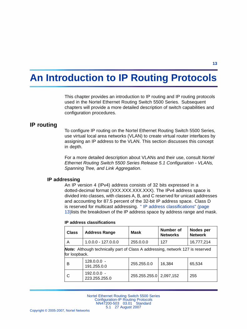
IP addressingAn IP version 4 (IPv4) address consists of 32 bits expressed in adotted-decimal format (XXX.XXX.XXX.XXX). The IPv4 address space isdivided into classes, with classes A, B, and C reserved for unicast addressesand accounting for 87.5 percent of the 32-bit IP address space. Class Dis reserved for multicast addressing. " IP address classifications" (page13)lists the breakdown of the IP address space by address range and mask.
IP address classifications
Class Address Range MaskNumber ofNetworks
Nodes perNetwork
A 1.0.0.0 - 127.0.0.0 255.0.0.0 127 16,777,214
Note: Although technically part of Class A addressing, network 127 is reservedfor loopback.
B128.0.0.0 -191.255.0.0
255.255.0.0 16,384 65,534
C192.0.0.0 -223.255.255.0
255.255.255.0 2,097,152 255
Nortel Ethernet Routing Switch 5500 SeriesConfiguration-IP Routing ProtocolsNN47200-503 03.01 Standard
5.1 27 August 2007Copyright © 2005-2007, Nortel Networks
.
14 An Introduction to IP Routing Protocols
Class Address Range Mask Number ofNetworks
Nodes perNetwork
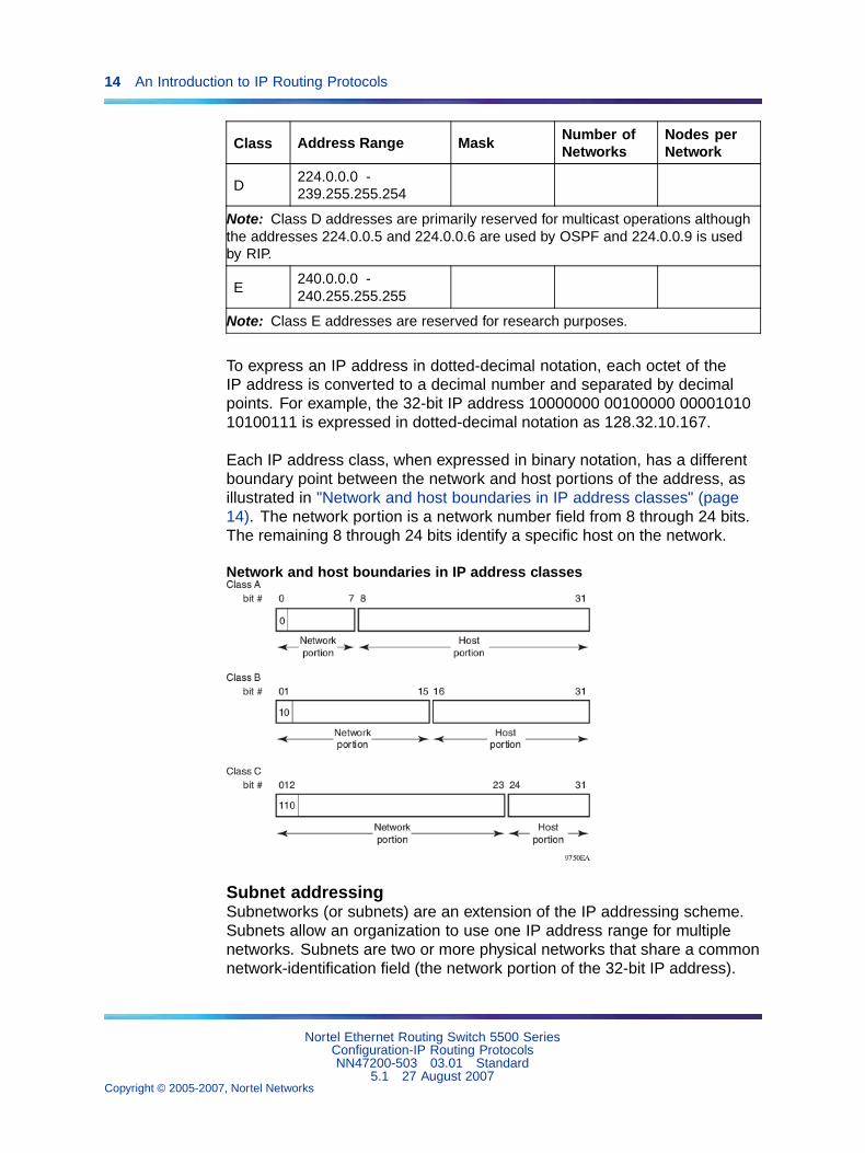
D224.0.0.0 -239.255.255.254
Note: Class D addresses are primarily reserved for multicast operations althoughthe addresses 224.0.0.5 and 224.0.0.6 are used by OSPF and 224.0.0.9 is usedby RIP.
E240.0.0.0 -240.255.255.255
Note: Class E addresses are reserved for research purposes.
To express an IP address in dotted-decimal notation, each octet of theIP address is converted to a decimal number and separated by decimalpoints. For example, the 32-bit IP address 10000000 00100000 0000101010100111 is expressed in dotted-decimal notation as 128.32.10.167.
Each IP address class, when expressed in binary notation, has a differentboundary point between the network and host portions of the address, asillustrated in "Network and host boundaries in IP address classes" (page14). The network portion is a network number field from 8 through 24 bits.The remaining 8 through 24 bits identify a specific host on the network.
Network and host boundaries in IP address classes
Subnet addressingSubnetworks (or subnets) are an extension of the IP addressing scheme.Subnets allow an organization to use one IP address range for multiplenetworks. Subnets are two or more physical networks that share a commonnetwork-identification field (the network portion of the 32-bit IP address).
Nortel Ethernet Routing Switch 5500 SeriesConfiguration-IP Routing ProtocolsNN47200-503 03.01 Standard
5.1 27 August 2007Copyright © 2005-2007, Nortel Networks
.
IP routing 15
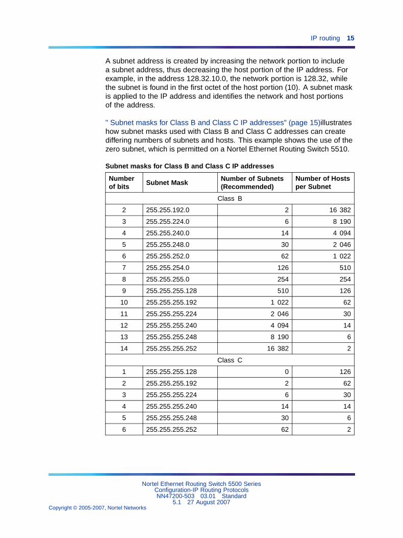
A subnet address is created by increasing the network portion to includea subnet address, thus decreasing the host portion of the IP address. Forexample, in the address 128.32.10.0, the network portion is 128.32, whilethe subnet is found in the first octet of the host portion (10). A subnet maskis applied to the IP address and identifies the network and host portionsof the address.
" Subnet masks for Class B and Class C IP addresses" (page 15)illustrateshow subnet masks used with Class B and Class C addresses can creatediffering numbers of subnets and hosts. This example shows the use of thezero subnet, which is permitted on a Nortel Ethernet Routing Switch 5510.
Subnet masks for Class B and Class C IP addresses
Numberof bits Subnet Mask
Number of Subnets(Recommended)
Number of Hostsper Subnet
Class B
2 255.255.192.0 2 16 382
3 255.255.224.0 6 8 190
4 255.255.240.0 14 4 094
5 255.255.248.0 30 2 046
6 255.255.252.0 62 1 022
7 255.255.254.0 126 510
8 255.255.255.0 254 254
9 255.255.255.128 510 126
10 255.255.255.192 1 022 62
11 255.255.255.224 2 046 30
12 255.255.255.240 4 094 14
13 255.255.255.248 8 190 6
14 255.255.255.252 16 382 2
Class C
1 255.255.255.128 0 126
2 255.255.255.192 2 62
3 255.255.255.224 6 30
4 255.255.255.240 14 14
5 255.255.255.248 30 6
6 255.255.255.252 62 2
Nortel Ethernet Routing Switch 5500 SeriesConfiguration-IP Routing ProtocolsNN47200-503 03.01 Standard
5.1 27 August 2007Copyright © 2005-2007, Nortel Networks
.
16 An Introduction to IP Routing Protocols
Variable-length subnet masking (VLSM) is the ability to divide an intranetinto pieces that match network requirements. Routing is based on thelongest subnet mask or network that matches.
IP routing using VLANsThe Nortel Ethernet Routing Switch 5500 Series supports wire-speed IProuting between virtual LANs (VLAN). This type of routing is also referred toas virtual routing. When a virtual router interface is created for a specifiedVLAN, a specific IP address is associated with the specific VLAN. In thisrelease, the Nortel Ethernet Routing Switch 5500 Series supports staticrouting, in which the identifiers of the devices being routed between areentered manually.
This virtual router interface does not have an association with any specifiedport or set of ports (it is called a virtual router interface because it is notassociated with any particular port). The VLAN IP address can be reachedthrough any of the ports in the VLAN specified as a virtual router interface,and the assigned IP address is the gateway through which packets arerouted out of that VLAN. Routed traffic can be forwarded to another VLANwithin the switch or stack of Nortel Ethernet Routing Switch 5500 Series.
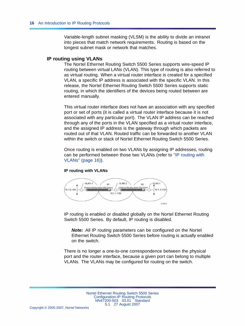
Once routing is enabled on two VLANs by assigning IP addresses, routingcan be performed between those two VLANs (refer to "IP routing withVLANs" (page 16)).
IP routing with VLANs
IP routing is enabled or disabled globally on the Nortel Ethernet RoutingSwitch 5500 Series. By default, IP routing is disabled.
Note: All IP routing parameters can be configured on the NortelEthernet Routing Switch 5500 Series before routing is actually enabledon the switch.
There is no longer a one-to-one correspondence between the physicalport and the router interface, because a given port can belong to multipleVLANs. The VLANs may be configured for routing on the switch.
Nortel Ethernet Routing Switch 5500 SeriesConfiguration-IP Routing ProtocolsNN47200-503 03.01 Standard
5.1 27 August 2007Copyright © 2005-2007, Nortel Networks
.
IP routing 17
As with any IP address, virtual router interface addresses are also used fordevice management. For management over IP, any virtual router interfaceIP address can be used to access the switch as long as routing is enabled.When the Nortel Ethernet Routing Switch 5500 Series switch or stack isused without routing enabled, the Management VLAN is reachable onlythrough the switch or stack IP address. With IP routing enabled on theswitch or stack, any of the virtual router IP interfaces can be used formanagement over IP.
Once routing is enabled on the Nortel Ethernet Routing Switch 5500 Seriesswitches, the Management VLAN behaves like all other routable VLANs.The IP address is reachable through any virtual router interface, as long asa route is available. Actually, all virtual router interfaces can be used as theManagement VLAN over IP.
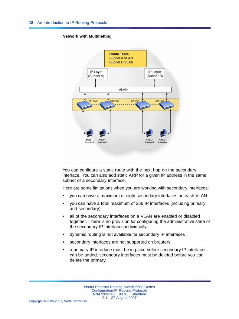
MultinettingThe Nortel Ethernet Routing Switch 5500 Series supports the definitionand configuration of up to eight secondary interfaces on each VLAN(multinetting). With IP multinetting, you can associate multiple IP subnetswith one VLAN. That is, connected hosts can belong to different IP subnetson the same VLAN.
Multinetting can be configured using the CLI or the Device Manager.
The following diagram illustrates a network with configured IP multinetting.
Nortel Ethernet Routing Switch 5500 SeriesConfiguration-IP Routing ProtocolsNN47200-503 03.01 Standard
5.1 27 August 2007Copyright © 2005-2007, Nortel Networks
.
18 An Introduction to IP Routing Protocols
Network with Multinetting
You can configure a static route with the next hop on the secondaryinterface. You can also add static ARP for a given IP address in the samesubnet of a secondary interface.
Here are some limitations when you are working with secondary interfaces:
• you can have a maximum of eight secondary interfaces on each VLAN
• you can have a total maximum of 256 IP interfaces (including primaryand secondary)
• all of the secondary interfaces on a VLAN are enabled or disabledtogether. There is no provision for configuring the administrative state ofthe secondary IP interfaces individually.
• dynamic routing is not available for secondary IP interfaces
• secondary interfaces are not supported on brouters
• a primary IP interface must be in place before secondary IP interfacescan be added; secondary interfaces must be deleted before you candelete the primary
Nortel Ethernet Routing Switch 5500 SeriesConfiguration-IP Routing ProtocolsNN47200-503 03.01 Standard
5.1 27 August 2007Copyright © 2005-2007, Nortel Networks
.
IP routing 19
If secondary interfaces are configured on the management VLAN, routingcannot be disabled globally or on the management VLAN. Secondary IPinterfaces on the management VLAN are purged from NVRAM when
• a unit leaves the stack and the switch does not have a manuallyconfigured IP
• the switch fails to get the IP address through the BootP mode
The following are not supported on secondary interfaces:
• DHCRP
• Proxy ARP
• UDP broadcast
• IPFIX
• VRRP, OSPF, RIP
For information about configuring secondary interfaces on VLANs, see "IProuting using VLANs" (page 16).
Brouter portThe Nortel Ethernet Routing Switch 5500 Series supports the conceptof brouter ports. A brouter port is a single-port VLAN that can route IPpackets as well as bridge all non-routable traffic. The difference betweena brouter port and a standard IP protocol-based VLAN configured to dorouting is that the routing interface of the brouter port is not subject tothe spanning tree state of the port. A brouter port can be in the blockingstate for non-routable traffic and still be able to route IP traffic. This featureremoves any interruptions caused by Spanning Tree Protocol recalculationsin routed traffic. A brouter port is actually a one-port VLAN; therefore, eachbrouter port decreases the number of available VLANs by one and usesone VLAN ID.
When a brouter port is created, the following actions are also taking placeon the switch:
• A port-based VLAN is created.
• The brouter port is added to the new port-based VLAN.
• The PVID of the brouter port is changed to the VLAN ID of the newVLAN.
• The STP participation of the brouter port is disabled.
• An IP address is assigned to the brouter VLAN.
Nortel Ethernet Routing Switch 5500 SeriesConfiguration-IP Routing ProtocolsNN47200-503 03.01 Standard
5.1 27 August 2007Copyright © 2005-2007, Nortel Networks
.
20 An Introduction to IP Routing Protocols
Management VLANPrior to Software Release 4.0, the Management VLAN was the only VLANthat was used to carry the management traffic, including Telnet, Web,SNMP, BootP and TFTP for the switch. The Management VLAN alwaysexists on the switch and cannot be removed. All IP settings, including switchIP address, stack IP address, subnet mask and default gateway, apply onlyto the Management VLAN.
In this release of Nortel Ethernet Routing Switch 5500 Series, a regularLayer 2 (L2) VLAN behaves like a routable L3 VLAN if a pair of IP addressesand a MAC address are attached to the VLAN. When routing is enabled inL3 mode, every L3 VLAN is capable of doing routing as well as carrying themanagement traffic. Any L3 VLAN can be used instead of the ManagementVLAN to manage the switch.
Layer 2 versus Layer 3 modeWhen the Nortel Ethernet Routing Switch 5500 Series is configured to routeIP traffic between different VLANs, the switch is considered to be running inL3 mode; otherwise, the switch runs in L2 mode.
The L3 manager determines in which mode a switch or a stack should berun. The mode is determined based on the user settings and events. Butthe general rule is to select:
• L3 mode: if routing is turned on globally for the switch or stack.
• L2 mode: if routing is turned off globally for the switch or stack.
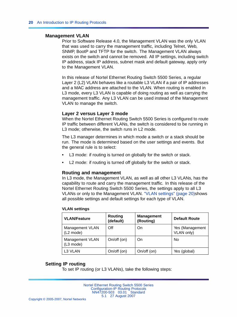
Routing and managementIn L3 mode, the Management VLAN, as well as all other L3 VLANs, has thecapability to route and carry the management traffic. In this release of theNortel Ethernet Routing Switch 5500 Series, the settings apply to all L3VLANs or only to the Management VLAN. "VLAN settings" (page 20)showsall possible settings and default settings for each type of VLAN.
VLAN settings
VLAN/FeatureRouting(default)
Management(Routing)
Default Route
Management VLAN(L2 mode)
Off On Yes (ManagementVLAN only)
Management VLAN(L3 mode)
On/off (on) On No
L3 VLAN On/off (on) On/off (on) Yes (global)
Setting IP routingTo set IP routing (or L3 VLANs), take the following steps:
Nortel Ethernet Routing Switch 5500 SeriesConfiguration-IP Routing ProtocolsNN47200-503 03.01 Standard
5.1 27 August 2007Copyright © 2005-2007, Nortel Networks
.
IP routing 21
Step Action
1 Enable IP routing globally.
2 Assign an IP address to the specific VLAN or brouter port.
3 Enable IP routing on the interface.
—End—
Refer to subsequent chapters in this document for detailed instructions onconfiguring IP routes.
Address Resolution Protocol (ARP)Address Resolution Protocol (ARP)Network stations using the IP protocol need both a physical address and anIP address to transmit a packet. If a network station knows only a networkhost’s IP address, the Address Resolution Protocol (ARP) enables thenetwork station to determine a network host’s physical address and bindthe 32-bit IP address to a 48-bit MAC address. A network station can useARP across a single network only, and the network hardware must supportphysical broadcasts.
If a network station wants to send a packet to a host but knows only thehost’s IP address, the network station uses ARP to determine the host’sphysical address as follows:
1. The network station broadcasts a special packet, called an ARP request,that asks the host at the specified IP address to respond with its physicaladdress.
2. All network hosts receive the broadcast message.
3. Only the specified host responds with its hardware address.
4. The network station then maps the host’s IP address to its physicaladdress and saves the results in an address resolution table for futureuse.
5. The network station’s ARP table displays the association of the knownMAC addresses to IP addresses.
Note: The default timeout value for ARP entries is 6 hours.
Static ARP entries can be created and individual ARP entries deleted.
Nortel Ethernet Routing Switch 5500 SeriesConfiguration-IP Routing ProtocolsNN47200-503 03.01 Standard
5.1 27 August 2007Copyright © 2005-2007, Nortel Networks
.
22 An Introduction to IP Routing Protocols
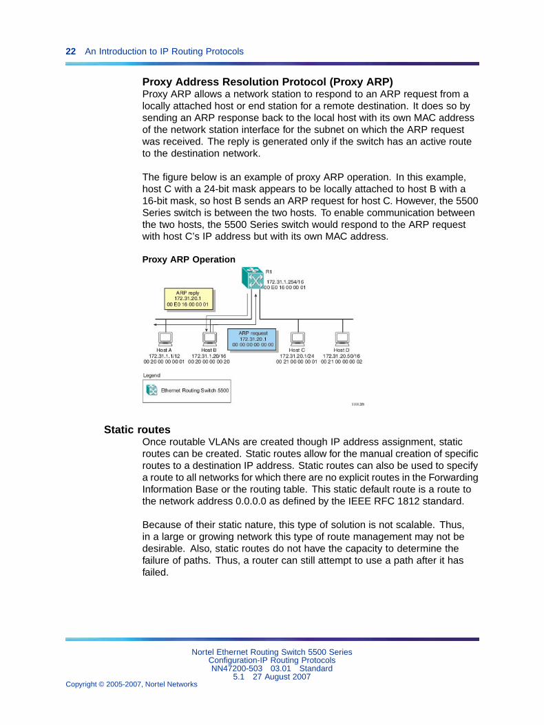
Proxy Address Resolution Protocol (Proxy ARP)Proxy ARP allows a network station to respond to an ARP request from alocally attached host or end station for a remote destination. It does so bysending an ARP response back to the local host with its own MAC addressof the network station interface for the subnet on which the ARP requestwas received. The reply is generated only if the switch has an active routeto the destination network.
The figure below is an example of proxy ARP operation. In this example,host C with a 24-bit mask appears to be locally attached to host B with a16-bit mask, so host B sends an ARP request for host C. However, the 5500Series switch is between the two hosts. To enable communication betweenthe two hosts, the 5500 Series switch would respond to the ARP requestwith host C’s IP address but with its own MAC address.
Proxy ARP Operation
Static routesOnce routable VLANs are created though IP address assignment, staticroutes can be created. Static routes allow for the manual creation of specificroutes to a destination IP address. Static routes can also be used to specifya route to all networks for which there are no explicit routes in the ForwardingInformation Base or the routing table. This static default route is a route tothe network address 0.0.0.0 as defined by the IEEE RFC 1812 standard.
Because of their static nature, this type of solution is not scalable. Thus,in a large or growing network this type of route management may not bedesirable. Also, static routes do not have the capacity to determine thefailure of paths. Thus, a router can still attempt to use a path after it hasfailed.
Nortel Ethernet Routing Switch 5500 SeriesConfiguration-IP Routing ProtocolsNN47200-503 03.01 Standard
5.1 27 August 2007Copyright © 2005-2007, Nortel Networks
.
IP routing 23
Non-local static routesThe Nortel Ethernet Routing Switch 5500 Series supports the usage ofnon-local static routes. A non-local static route is almost identical to astatic route with the exception that the next hop of the route is not directlyconnected to the network entity. Non-local static routes are useful insituations where there are multiple paths to a network and the numberof static routes could be reduced by using only one route with a remotegateway.
Because of their static nature, this type of solution is not scalable. Thus,in a large or growing network this type of route management may notbe desirable. Also, non-local static routes do not have the capacity todetermine the failure of paths. Thus, a router can still attempt to use a pathafter it has failed.
Routing Information Protocol (RIP)Routing Information Protocol (RIP) is a standard, dynamic routing protocolbased on the Bellman-Ford (or distance vector) algorithm. It is used as anInterior Gateway Protocol (IGP). RIP allows routers to exchange informationto compute routes through an IPv4-based network. The hop count, ordistance, is used as a metric to determine the best path to a remote networkor host. The hop count cannot exceed 15 hops (assuming a cost of onehop for each network).
RIP is defined in RFC 1058 for RIP version 1 and RFC 2453 for RIP version2. The most significant difference between the two versions is that RIPversion 2 supports subnet masks and next hop information in the RIPpacket.
RIP operationRIP uses User Datagram Protocol (UDP) data packets to exchangerouting information. Each router maintains a routing table, which lists theoptimal route to every destination in the system. Each router advertisesits routing information by sending a routing information update at regularintervals. Neighboring routers use this information to recalculate theirrouting tables and retransmit the routing information. For RIP version 1,no mask information is exchanged; the natural mask is always applied bythe router receiving the update. For RIP version 2, mask information isalways included.
The sequence of processes governed by the routing algorithm is as follows:
1. When a router starts, it initializes the RIP data structures and then waitsfor indications from lower-level protocols that its interfaces are functional.
2. RIP advertisements are send on all the interfaces that are configured tosend routing information.
Nortel Ethernet Routing Switch 5500 SeriesConfiguration-IP Routing ProtocolsNN47200-503 03.01 Standard
5.1 27 August 2007Copyright © 2005-2007, Nortel Networks
.
24 An Introduction to IP Routing Protocols
3. The neighbors will send their routing tables and the new router willupdate its routing table based on the advertisements received.
4. From now on periodic updates are send by each router in the network toensure a correct routing database.
If a router does not receive an update from another router within a timeoutperiod, it deletes the routes served by the nonupdating router from itsrouting table. However, it keeps these routes temporarily in a garbage listand continues to advertise them with a metric of 16 for a holddown period,so that neighbors know that the routes are unreachable. If a valid updatefor a garbage route is received within the holddown period, the router addsthe route back into its routing table. If no update is received, the routercompletely deletes all garbage list entries for the nonupdating router.
To prevent routing loops and to promote fast convergence, RIP usesthe mechanisms of split horizon, with or without poisoned reverse, andtriggered updates. Simple split horizon means that IP routes learned from aneighbor are not advertised back in updates to that neighbor. Split horizonwith poisoned reverse means that these routes are advertised back to theneighbor, but they are “poisoned” with a metric of 16, which representsinfinite hops in the network. The receiver neighbor therefore ignores thisroute. Triggered updates means that a router is required to send updatemessages whenever it changes the metric for a route, even if it is not yettime for a regular update message.
RIP sends routing information updates every 30 seconds. These updatescontain information about known networks and the distances (hop count)associated with each. For RIP version 1, no mask information is exchanged;the natural mask is always applied by the router receiving the update. Maskinformation is always included for RIP version 2.
If information about a network is not received for within the allotted timeoutperiod (180 seconds by default), it is removed from the routing table and theroute is moved to the garbage list . From the garbage list it will be advertisedfor the allotted holdown period (120 seconds by default) with metric set toinfinity (16). These timers can be changed by configuring the RIP InterfaceTimeout Timer and Holddown Timer parameters.
RIP supports the following standard behavior:
• periodic RIP updates about effective best routes
• garbage collection
• split horizon with or without poisoned reverse
• triggered update for changed RIP routes
• unicast to the specific query requestor
• broadcast/multicast of regular and triggered updates
Nortel Ethernet Routing Switch 5500 SeriesConfiguration-IP Routing ProtocolsNN47200-503 03.01 Standard
5.1 27 August 2007Copyright © 2005-2007, Nortel Networks
.
IP routing 25
• subnet mask (RIP version 2)
• routing table update based on the received RIP message
• global update timer
• holddown timer and timeout timer per device and per interface
• cost per device and per interface
The Nortel Ethernet Routing Switch 5500 Series implementation of RIPalso supports the following features:
• in and out routing policies
• auto-aggregation (also known as auto-summarization) of groups ofadjacent routes into single entries
Many RIP features are configurable. The actual behavior of the protocoldepends on the feature configurations.
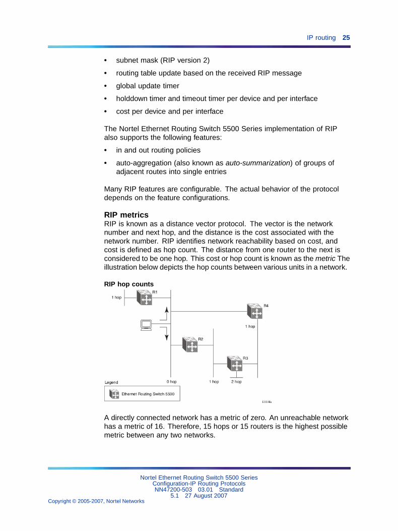
RIP metricsRIP is known as a distance vector protocol. The vector is the networknumber and next hop, and the distance is the cost associated with thenetwork number. RIP identifies network reachability based on cost, andcost is defined as hop count. The distance from one router to the next isconsidered to be one hop. This cost or hop count is known as the metric Theillustration below depicts the hop counts between various units in a network.
RIP hop counts
A directly connected network has a metric of zero. An unreachable networkhas a metric of 16. Therefore, 15 hops or 15 routers is the highest possiblemetric between any two networks.
Nortel Ethernet Routing Switch 5500 SeriesConfiguration-IP Routing ProtocolsNN47200-503 03.01 Standard
5.1 27 August 2007Copyright © 2005-2007, Nortel Networks
.
26 An Introduction to IP Routing Protocols
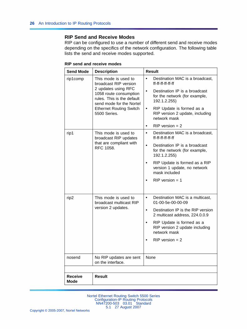
RIP Send and Receive ModesRIP can be configured to use a number of different send and receive modesdepending on the specifics of the network configuration. The following tablelists the send and receive modes supported.
RIP send and receive modes
Send Mode Description Result
rip1comp This mode is used tobroadcast RIP version2 updates using RFC1058 route consumptionrules. This is the defaultsend mode for the NortelEthernet Routing Switch5500 Series.
• Destination MAC is a broadcast,ff-ff-ff-ff-ff-ff
• Destination IP is a broadcastfor the network (for example,192.1.2.255)
• RIP Update is formed as aRIP version 2 update, includingnetwork mask
• RIP version = 2
rip1 This mode is used tobroadcast RIP updatesthat are compliant withRFC 1058.
• Destination MAC is a broadcast,ff-ff-ff-ff-ff-ff
• Destination IP is a broadcastfor the network (for example,192.1.2.255)
• RIP Update is formed as a RIPversion 1 update, no networkmask included
• RIP version = 1
rip2 This mode is used tobroadcast multicast RIPversion 2 updates.
• Destination MAC is a multicast,01-00-5e-00-00-09
• Destination IP is the RIP version2 multicast address, 224.0.0.9
• RIP Update is formed as aRIP version 2 update includingnetwork mask
• RIP version = 2
nosend No RIP updates are senton the interface.
None
ReceiveMode
Result
Nortel Ethernet Routing Switch 5500 SeriesConfiguration-IP Routing ProtocolsNN47200-503 03.01 Standard
5.1 27 August 2007Copyright © 2005-2007, Nortel Networks
.
IP routing 27
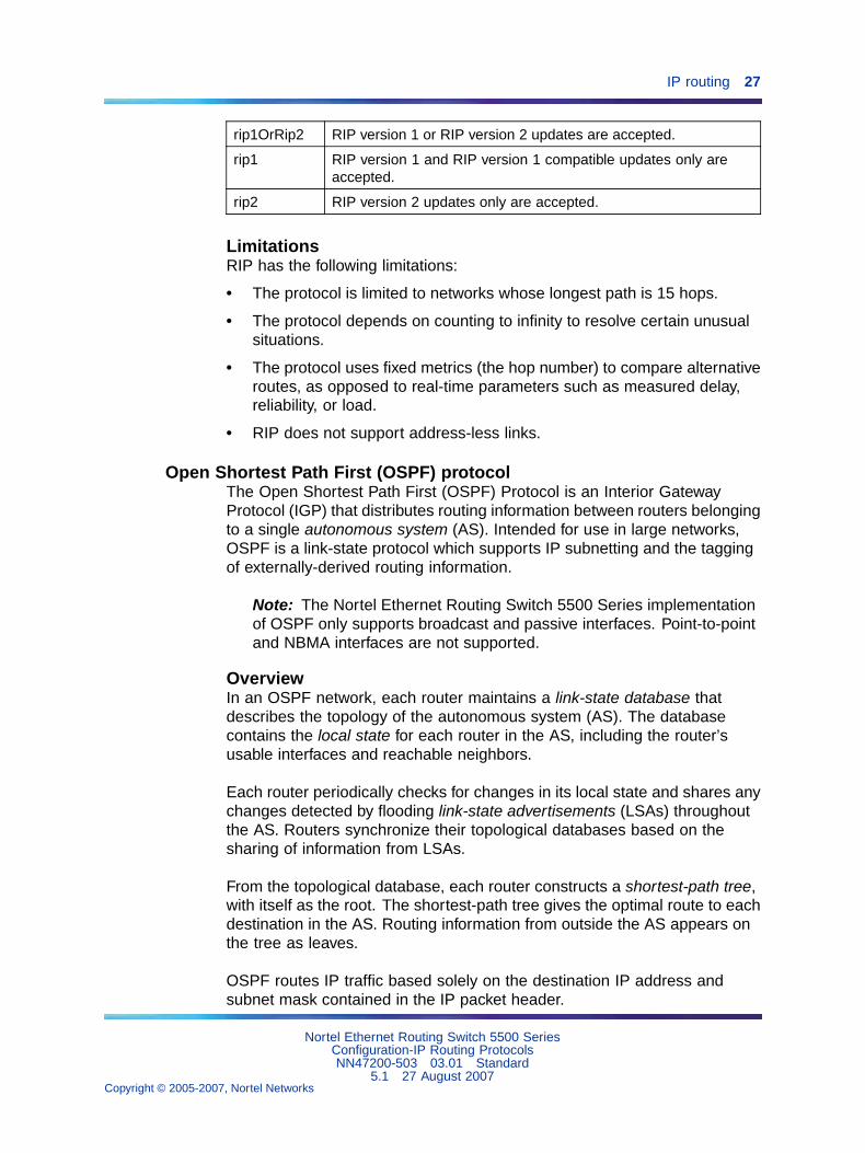
rip1OrRip2 RIP version 1 or RIP version 2 updates are accepted.
rip1 RIP version 1 and RIP version 1 compatible updates only areaccepted.
rip2 RIP version 2 updates only are accepted.
LimitationsRIP has the following limitations:
• The protocol is limited to networks whose longest path is 15 hops.
• The protocol depends on counting to infinity to resolve certain unusualsituations.
• The protocol uses fixed metrics (the hop number) to compare alternativeroutes, as opposed to real-time parameters such as measured delay,reliability, or load.
• RIP does not support address-less links.
Open Shortest Path First (OSPF) protocolThe Open Shortest Path First (OSPF) Protocol is an Interior GatewayProtocol (IGP) that distributes routing information between routers belongingto a single autonomous system (AS). Intended for use in large networks,OSPF is a link-state protocol which supports IP subnetting and the taggingof externally-derived routing information.
Note: The Nortel Ethernet Routing Switch 5500 Series implementationof OSPF only supports broadcast and passive interfaces. Point-to-pointand NBMA interfaces are not supported.
OverviewIn an OSPF network, each router maintains a link-state database thatdescribes the topology of the autonomous system (AS). The databasecontains the local state for each router in the AS, including the router’susable interfaces and reachable neighbors.
Each router periodically checks for changes in its local state and shares anychanges detected by flooding link-state advertisements (LSAs) throughoutthe AS. Routers synchronize their topological databases based on thesharing of information from LSAs.
From the topological database, each router constructs a shortest-path tree,with itself as the root. The shortest-path tree gives the optimal route to eachdestination in the AS. Routing information from outside the AS appears onthe tree as leaves.
OSPF routes IP traffic based solely on the destination IP address andsubnet mask contained in the IP packet header.
Nortel Ethernet Routing Switch 5500 SeriesConfiguration-IP Routing ProtocolsNN47200-503 03.01 Standard
5.1 27 August 2007Copyright © 2005-2007, Nortel Networks
.
28 An Introduction to IP Routing Protocols
BenefitsBenefits in large networks OSPF offers the following benefits:
• Fast convergence
In the event of topological changes, OSPF recalculates routes quickly.
• Minimal routing protocol traffic
Unlike distance vector routing protocols such as RIP, OSPF generates aminimum of routing protocol traffic.
• Load sharing
OSPF provides support for equal-cost multipath routing. If severalequal-cost routes to a destination exist, traffic is distributed equallyamong them.
• Because OSPF does not use hop count in its calculation, the routingdomain is scalable.
OSPF routing algorithmA separate copy of the OSPF routing algorithm runs in each area. Routerswhich are connected to multiple areas run multiple copies of the algorithm.The sequence of processes governed by the routing algorithm is as follows:
1. When a router starts, it initializes the OSPF data structures and thenwaits for indications from lower-level protocols that its interfaces arefunctional.
2. A router then uses the Hello Protocol to discover neighbors. Onpoint-to-point and broadcast networks the router dynamically detectsits neighbors by sending hello packets to the multicast addressAllSPFRouters. On non-broadcast multiaccess networks, someconfiguration information is required in order to discover neighbors.
3. On all multiaccess networks (broadcast or non-broadcast), the HelloProtocol also elects a DR for the network.
4. The router attempts to form adjacencies with some of its neighbors.On multiaccess networks, the DR determines which routers becomeadjacent. This behavior does not occur if a router is configured as apassive interface, because passive interfaces do not form adjacencies.
5. Adjacent neighbors synchronize their topological databases.
6. The router periodically advertises its link-state, and also does so whenits local state changes. LSAs include information about adjacenciesenabling quick detection of dead routers on the network.
7. LSAs are flooded throughout the area, ensuring that all routers in anarea have exactly the same topological database.
Nortel Ethernet Routing Switch 5500 SeriesConfiguration-IP Routing ProtocolsNN47200-503 03.01 Standard
5.1 27 August 2007Copyright © 2005-2007, Nortel Networks
.
IP routing 29
8. From this database each router calculates a shortest-path tree, withitself as root. This shortest-path tree in turn yields a routing table forthe protocol.
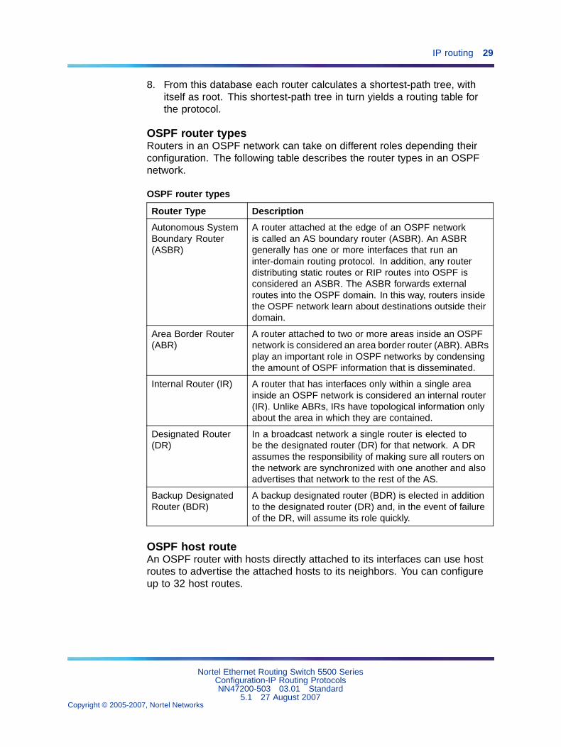
OSPF router typesRouters in an OSPF network can take on different roles depending theirconfiguration. The following table describes the router types in an OSPFnetwork.
OSPF router types
Router Type Description
Autonomous SystemBoundary Router(ASBR)
A router attached at the edge of an OSPF networkis called an AS boundary router (ASBR). An ASBRgenerally has one or more interfaces that run aninter-domain routing protocol. In addition, any routerdistributing static routes or RIP routes into OSPF isconsidered an ASBR. The ASBR forwards externalroutes into the OSPF domain. In this way, routers insidethe OSPF network learn about destinations outside theirdomain.
Area Border Router(ABR)
A router attached to two or more areas inside an OSPFnetwork is considered an area border router (ABR). ABRsplay an important role in OSPF networks by condensingthe amount of OSPF information that is disseminated.
Internal Router (IR) A router that has interfaces only within a single areainside an OSPF network is considered an internal router(IR). Unlike ABRs, IRs have topological information onlyabout the area in which they are contained.
Designated Router(DR)
In a broadcast network a single router is elected tobe the designated router (DR) for that network. A DRassumes the responsibility of making sure all routers onthe network are synchronized with one another and alsoadvertises that network to the rest of the AS.
Backup DesignatedRouter (BDR)
A backup designated router (BDR) is elected in additionto the designated router (DR) and, in the event of failureof the DR, will assume its role quickly.
OSPF host routeAn OSPF router with hosts directly attached to its interfaces can use hostroutes to advertise the attached hosts to its neighbors. You can configureup to 32 host routes.
Nortel Ethernet Routing Switch 5500 SeriesConfiguration-IP Routing ProtocolsNN47200-503 03.01 Standard
5.1 27 August 2007Copyright © 2005-2007, Nortel Networks
.
30 An Introduction to IP Routing Protocols
Host routes are managed with Nortel Networks Command Line Interface(NNCLI) commands and SNMP MIBs and are identified by the host IPaddress and the configured route type of service (TOS). For each hostdirectly connected to the router, configure the cost of the link to the hostduring host creation. You cannot modify this cost.
Note: Always set TOS to 0 because TOS-based routing is notsupported.
When a host is added to, or deleted from, a host route, the router updatesthe router LSAs and floods them to neighbors in each area where thatrouter has an interface.
Following is an example of parameters for a host route advertised in the LSA.
Host route in LSA
• Type: 3 (stub network)
• LinkID: IP address of host directly connected to router
• Link Data: 0xFFFFFFFF
• Metric: configured cost of host
OSPF Enhancements
• Host route - Allows a router to advertise to its neighbors all hosts thatare directly attached to that router’s interfaces. Up to 32 host routescan be configured.
• Virtual links - The OSPF network can be partitioned into multipleareas. However, a backbone area must exist and be contiguous, andevery non-backbone area must be connected to the backbone areausing either a physical or a logical link. In a network where a physicalconnection between the non-backbone area and backbone area isimpossible, use of a virtual link provides the logical connection throughanother non-backbone area, called the transit area. Virtual links can becreated manually or automatically. The 5500 Series switch supportsup to 16 virtual links.
When 5500 Series switches are stacked, and a unit leaves the stack andbecomes standalone, the router ID is automatically changed to its defaultvalue if IP blocking is turned off and OSPF is globally enabled. Thisprevents duplication of a router ID in the OSPF routing domain. The newrouter ID value is temporary, that is, it is not saved to NVRAM. Therefore,upon reset, the old router ID is restored. Configurable using NNCLI, ACG,and Device Manager.
Example configurations The following is an example for creating a hostroute:
Nortel Ethernet Routing Switch 5500 SeriesConfiguration-IP Routing ProtocolsNN47200-503 03.01 Standard
5.1 27 August 2007Copyright © 2005-2007, Nortel Networks
.

IP routing 31
Creating Host Route
Example : 1R3(config)#router ospfR3(config-router)#host-route 11.11.11.111 metric 10R3(config-router)#show ip ospf host-route
Host IP Metric
11.11.11.111 10
R3(config-router)#
The following is an example for deleting a host route:
Deleting Host Route
Example : 1R3(config-router)#no host-route 11.11.11.111R3(config-router)#show ip ospf host-route
Host IP Metric
R3(config-router)#
OSPF virtual linkOn an OSPF network, a router acting as an area boundary router (ABR)must be directly connected to the backbone. If no physical connection isavailable, you can create a virtual link.
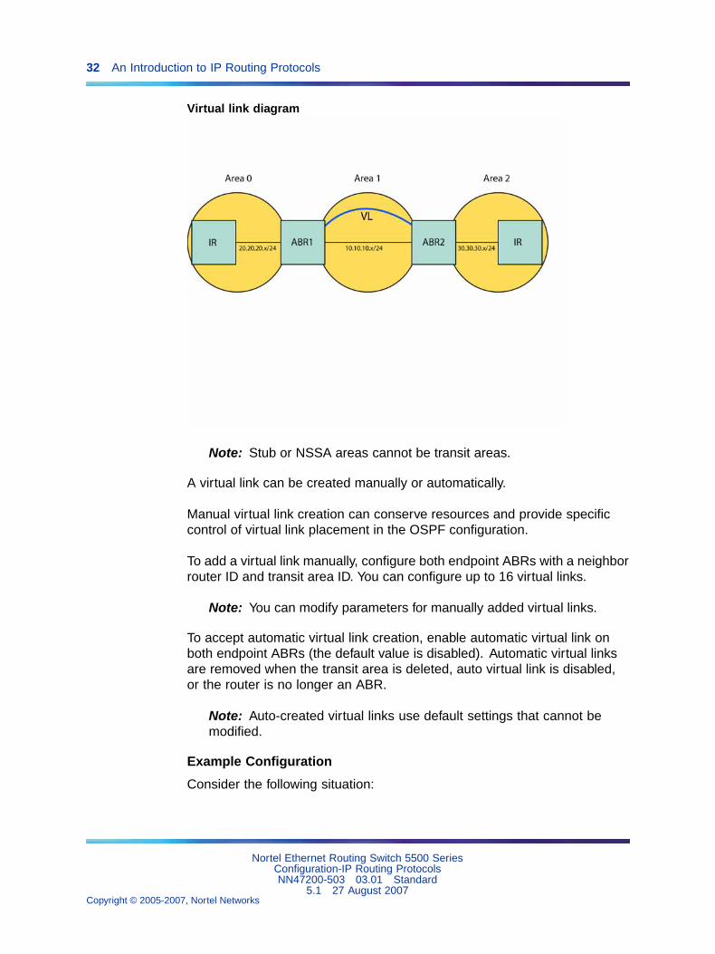
A virtual link is established between two endpoint ABRs and is a logicalconnection to the backbone area through a non-backbone area called atransit area. In the following diagram, non-backbone ABR 2 establishes avirtual link with backbone ABR1 across transition area, area 1. The virtuallink connects area 2 to area 0.
Nortel Ethernet Routing Switch 5500 SeriesConfiguration-IP Routing ProtocolsNN47200-503 03.01 Standard
5.1 27 August 2007Copyright © 2005-2007, Nortel Networks
.
32 An Introduction to IP Routing Protocols
Virtual link diagram
Note: Stub or NSSA areas cannot be transit areas.
A virtual link can be created manually or automatically.
Manual virtual link creation can conserve resources and provide specificcontrol of virtual link placement in the OSPF configuration.
To add a virtual link manually, configure both endpoint ABRs with a neighborrouter ID and transit area ID. You can configure up to 16 virtual links.
Note: You can modify parameters for manually added virtual links.
To accept automatic virtual link creation, enable automatic virtual link onboth endpoint ABRs (the default value is disabled). Automatic virtual linksare removed when the transit area is deleted, auto virtual link is disabled,or the router is no longer an ABR.
Note: Auto-created virtual links use default settings that cannot bemodified.
Example Configuration
Consider the following situation:
Nortel Ethernet Routing Switch 5500 SeriesConfiguration-IP Routing ProtocolsNN47200-503 03.01 Standard
5.1 27 August 2007Copyright © 2005-2007, Nortel Networks
.
IP routing 33
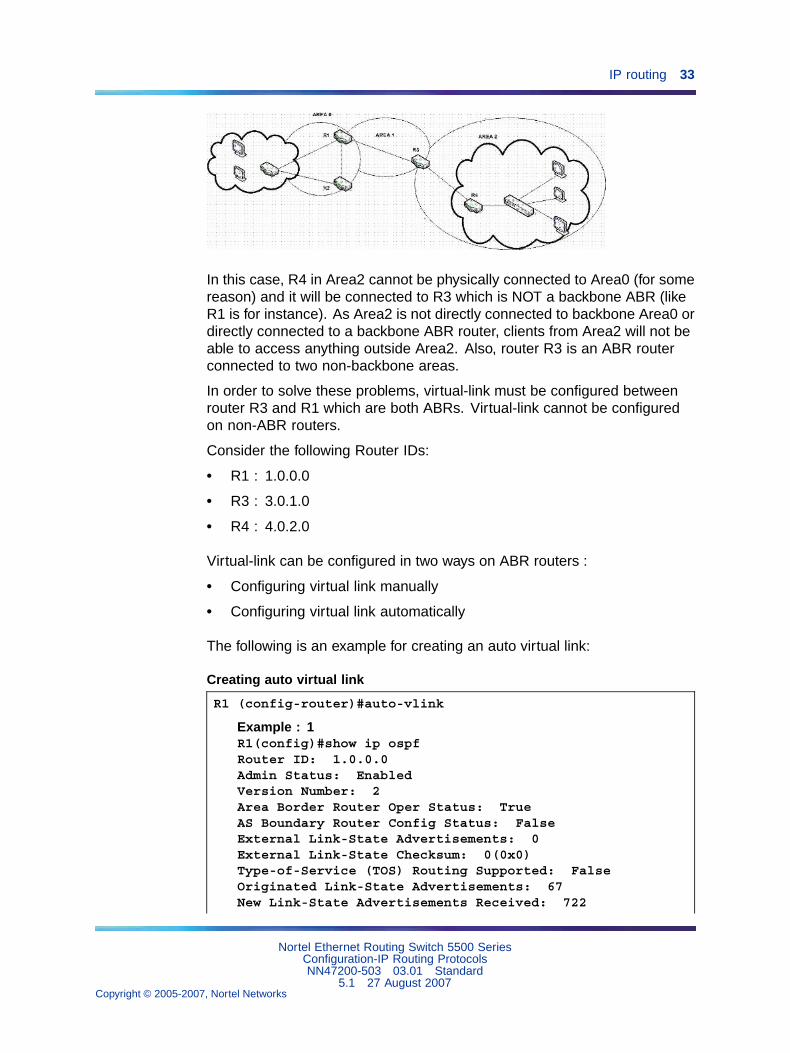
In this case, R4 in Area2 cannot be physically connected to Area0 (for somereason) and it will be connected to R3 which is NOT a backbone ABR (likeR1 is for instance). As Area2 is not directly connected to backbone Area0 ordirectly connected to a backbone ABR router, clients from Area2 will not beable to access anything outside Area2. Also, router R3 is an ABR routerconnected to two non-backbone areas.
In order to solve these problems, virtual-link must be configured betweenrouter R3 and R1 which are both ABRs. Virtual-link cannot be configuredon non-ABR routers.
Consider the following Router IDs:
• R1 : 1.0.0.0
• R3 : 3.0.1.0
• R4 : 4.0.2.0
Virtual-link can be configured in two ways on ABR routers :
• Configuring virtual link manually
• Configuring virtual link automatically
The following is an example for creating an auto virtual link:
Creating auto virtual link
R1 (config-router)#auto-vlink
Example : 1R1(config)#show ip ospfRouter ID: 1.0.0.0Admin Status: EnabledVersion Number: 2Area Border Router Oper Status: TrueAS Boundary Router Config Status: FalseExternal Link-State Advertisements: 0External Link-State Checksum: 0(0x0)Type-of-Service (TOS) Routing Supported: FalseOriginated Link-State Advertisements: 67New Link-State Advertisements Received: 722
Nortel Ethernet Routing Switch 5500 SeriesConfiguration-IP Routing ProtocolsNN47200-503 03.01 Standard
5.1 27 August 2007Copyright © 2005-2007, Nortel Networks
.
34 An Introduction to IP Routing Protocols
OSPF Traps: DisabledAuto Virtual Link Creation: EnabledSPF Hold-Down Time: 10RFC 1583 Compatibility: Enabled
R3 (config-router)#auto-vlink
Example : 2R3(config)#show ip ospfRouter ID: 3.0.1.0Admin Status: EnabledVersion Number: 2Area Border Router Oper Status: TrueAS Boundary Router Config Status: FalseExternal Link-State Advertisements: 0External Link-State Checksum: 0(0x0)Type-of-Service (TOS) Routing Supported: FalseOriginated Link-State Advertisements: 67New Link-State Advertisements Received: 722OSPF Traps: DisabledAuto Virtual Link Creation: EnabledSPF Hold-Down Time: 10RFC 1583 Compatibility: Enabled
The following is an example for deleting an auto virtual link:
Deleting auto virtual link
R1 (config-router)#no auto-vlink
Example : 1R1(config)#show ip ospfRouter ID: 1.0.0.0Admin Status: EnabledVersion Number: 2Area Border Router Oper Status: TrueAS Boundary Router Config Status: FalseExternal Link-State Advertisements: 0External Link-State Checksum: 0(0x0)Type-of-Service (TOS) Routing Supported: FalseOriginated Link-State Advertisements: 67New Link-State Advertisements Received: 722OSPF Traps: DisabledAuto Virtual Link Creation: DisabledSPF Hold-Down Time: 10RFC 1583 Compatibility: Enabled
R3 (config-router)#no auto-vlink
Example : 2R3(config)#show ip ospf
Nortel Ethernet Routing Switch 5500 SeriesConfiguration-IP Routing ProtocolsNN47200-503 03.01 Standard
5.1 27 August 2007Copyright © 2005-2007, Nortel Networks
.
IP routing 35
Router ID: 3.0.1.0Admin Status: EnabledVersion Number: 2Area Border Router Oper Status: TrueAS Boundary Router Config Status: FalseExternal Link-State Advertisements: 0External Link-State Checksum: 0(0x0)Type-of-Service (TOS) Routing Supported: FalseOriginated Link-State Advertisements: 67New Link-State Advertisements Received: 722OSPF Traps: DisabledAuto Virtual Link Creation: DisabledSPF Hold-Down Time: 10RFC 1583 Compatibility: Enabled
Virtual-Link can also be configured using the Java Device Manager (JDM).Just go under IP Routing > OSPF menu. There you can find : ‘General’ tabfor Auto-Vlink creation, ‘Virtual If’ tab, and ‘Virtual Neighbors’ tab.
Route policiesRoute policies are a Nortel proprietary improvement on existing routingschemes. Using existing routing schemes, packets are forwarded basedon routes that have been learned by the router through routing protocolssuch as RIP and OSPF or through the introduction of static routes. Routepolicies introduce the ability to forward packets based on rule sets createdby the network administrator. These rule sets, or policies, are then appliedto the learned or static routes.
Route policies on the Nortel Ethernet Routing Switch 5500 Series supportsthe Routing Information Protocol (RIP) and Open Shortest Path First(OSPF) protocol. When used in conjunction with these protocols, routepolicies can be used to perform the following tasks that are not possibleusing traditional routing methods:
• Listen for routing updates from specific gateways.
• Listen for routing updates from specific networks.
• Assign a specific subnet mask to be included with a network in therouting table.
• Advertise routing updates from specific gateways.
• Advertise routing updates to specific networks.
• Assign a specific subnet mask to be included in the route summarypackets.
• Advertise routes learned by one protocol to another.
Nortel Ethernet Routing Switch 5500 SeriesConfiguration-IP Routing ProtocolsNN47200-503 03.01 Standard
5.1 27 August 2007Copyright © 2005-2007, Nortel Networks
.
36 An Introduction to IP Routing Protocols
Route policies supports the following types of policies:
• Accept (In) Policies
Accept polices are applied to incoming routing updates before they areapplied to the routing table. In the case of RIP, accept policies can beapplied to all incoming packets and only one policy can be createdfor each RIP interface. In the case of OSPF, accept policies are onlyapplied to Type 5 External routes based on the advertising router ID.There can only be one OSPF accept policy per switch and the policyis applied before updates are added to the routing table from the linkstate database.
• Announce (Out) Policies
Announce policies are applied to outgoing routing updates beforethe routing update packets are actually transmitted from the switch.In the case of RIP, announce policies can be applied to all outgoingpackets and only one policy can be created for each RIP interface.Announce policies are not supported for OSPF as OSPF requiresrouting information to be consistent throughout the OSPF domain.
• Redistribution Policies
Redistribution policies are used to provide notification of addition ordeletion of a route in the routing table by one protocol to anotherprotocol. OSPF redistribution policies send redistributed routes as Type5 External routes. There can be only one OSPF redistribution route perswitch and it must be configured as a ASBR with redistribution enabled.
Route policies consist of the following items:
• Prefix Lists
— List of IP addresses with subnet masks.
— Identified by a prefix list name and unique identifier.
— Prefix lists support the comparison of ranges of incoming masks.
• Route Maps
— Contain a set of match and set parameters.
— Match and set parameters can contain several prefix lists.
— A set of match and set parameters are identified by a sequencenumber.
— Accept and deny actions are associated with each sequencedparameter set.
— Sequence numbers act as a preference setting. Sets with a lowersequence number are preferred over those with a higher sequencenumber.
Nortel Ethernet Routing Switch 5500 SeriesConfiguration-IP Routing ProtocolsNN47200-503 03.01 Standard
5.1 27 August 2007Copyright © 2005-2007, Nortel Networks
.
IP routing 37
To configure routing policies, create the appropriate prefix lists and thenassign those prefix lists to route maps. Once all route maps have beencreated, assign them to the appropriate type of policy.
In a stacked environment, the following rules are applied to routing policies:
• The policy database is stored in all stack units.
• Policy configuration is supported from only the base unit. The baseunit sends updates to non-base units to update the policy database ineach stack unit.
• During database updates, only the database in the base unit issynchronized with the non-base unit. The database in the non-baseunits are deleted during the exchange.
• Only the policies stored in the base unit are used by RIP and OSPFfor policy application.
Virtual Router Redundancy Protocol (VRRP)The Virtual Router Redundancy Protocol (VRRP) is designed to eliminatethe single point of failure that can occur when the single static defaultgateway router for an end station is lost. VRRP introduces the concept ofa virtual IP address (transparent to users) shared between two or morerouters connecting a common subnet to the enterprise network. With thevirtual IP address as the default gateway on end hosts, VRRP providesdynamic default gateway redundancy in the event of failure.
VRRP uses the following terms:
• VRRP router - a router running the VRRP protocol.
• Virtual router - the abstract object managed by VRRP that is assignedthe virtual IP address and that acts as the default router for a set of IPaddresses across a common network. Each virtual router is assigned avirtual router ID.
• Virtual router master - the VRRP router that assumes responsibilityfor forwarding packets sent to the IP address associated with the virtualrouter. The master router also responds to packets sent to the virtualrouter IP address and answers ARP requests for this IP address.
• Virtual router backup - the router or routers that can serve as thefailover router if the master router becomes unavailable. If the masterrouter fails, an election process provides a dynamic transition offorwarding responsibility to a new master router.
• Priority - an 8-bit value assigned to all VRRP routers. A higher valuerepresents a higher priority for election to the master router. The prioritycan be a value from 1 to 255. When a master router fails, an electionprocess takes place among the backup routers to dynamically reassignthe role of the master router.
Nortel Ethernet Routing Switch 5500 SeriesConfiguration-IP Routing ProtocolsNN47200-503 03.01 Standard
5.1 27 August 2007Copyright © 2005-2007, Nortel Networks
.

38 An Introduction to IP Routing Protocols
Equal Cost MultiPath (ECMP)The Equal Cost MultiPath (ECMP) feature allows routers to determine equalcost paths to the same destination prefix. The multiple paths can be usedfor load sharing of traffic and allows faster convergence to other active pathsin case of network failure. By maximizing load sharing among equal-costpaths, links between routers can be used more efficiently when sendingIP traffic. The ECMP feature supports and complements the followingprotocols types:
• Open Shortest Path First (OSPF)
• Routing Information Protocol (RIP)
• Static Routes
ECMP is only supported on the Nortel Ethernet Routing Switch 5520 and5530. ECMP will work in a mixed stack but will not run on any NortelEthernet Routing Switch 5510 units in the stack.
UDP broadcast forwardingSome network applications, such as the NetBIOS name service, relyon User Datagram Protocol (UDP) broadcasts to request a service orlocate a application. If a host is on a network, subnet segment, or VLANthat includes a server for the service, UDP broadcasts are by default notforwarded to the server located on a different network segment or VLAN.This is resolved by forwarding the broadcasts to the server through physicalor virtual interfaces.
UDP broadcast forwarding is a general mechanism for selectively forwardinglimited UDP broadcasts received on an IP interface to a configured IPaddress. The packet is sent as a unicast packet to the server.
The following are the basic steps for UDP broadcast forwardingconfiguration:
1. Enter the UDP protocols to be forwarded.
2. Create forwarding policies by defining UDP protocol and server pairs.
3. Assemble these policies into lists.
4. Apply these lists to the appropriate interfaces.
When a UDP broadcast is received on a router interface, it must meet thefollowing criteria if it is to be considered for forwarding:
• It must be a MAC-level broadcast.
• It must be an IP-limited broadcast.
• It must be for a configured UDP protocol.
• It must have a TTL value of at least 2.
Nortel Ethernet Routing Switch 5500 SeriesConfiguration-IP Routing ProtocolsNN47200-503 03.01 Standard
5.1 27 August 2007Copyright © 2005-2007, Nortel Networks
.
IP routing 39
For each ingress interface and protocol, the UDP broadcast packets areforwarded only to a unicast host address (the unicast IP address of theserver for example).
Dynamic Host Configuration Protocol (DHCP) / Bootstrap Protocol(BootP)
DHCP-BootP relayThe Dynamic Host Configuration Protocol (DHCP) is an extension of theBootstrap protocol (BootP) and provides host configuration information toworkstations on a dynamic basis. To lower administrative overhead, networkmanagers prefer to configure a small number of DHCP servers in a centrallocation. It is necessary for routers to support the BootP/DHCP relayfunction so that hosts can access configuration information from serversseveral router hops away.
Differences between DHCP and BootPThe following differences between DHCP and BootP are specified in RFC2131 and include functions that BootP does not address:
• The Nortel Ethernet Routing Switch 5500 Series supports the Bootstrapprotocol (BootP). BootP enables the retrieval of an ASCII configurationfile name and configuration server address.
• A properly configured BootP server enables the switch to automaticallylearn its assigned IP address, subnet mask and the IP address of thedefault router (default gateway).
• DHCP defines mechanisms through which clients can be assigned anetwork address for a finite lease (allowing for reuse of IP addresses).
• DHCP provides the mechanism for clients to acquire all of the IPconfiguration parameters needed to operate.
DHCP uses the BootP message format defined in RFC 951. The remainderof the options field consists of a list of tagged parameters that are called"options" (RFC 2131).
Summary of DHCP relay operationBootP/DHCP clients (workstations) generally use UDP/IP broadcasts todetermine their IP addresses and configuration information. If such a hostis on a network or a subnet segment (or VLAN) that does not include aDHCP server, the UDP broadcasts are by default not forwarded to theserver located on a different network segment or VLAN. The Nortel EthernetRouting Switch 5500 Series can be configured to resolve this issue byforwarding the broadcasts to the server. The router interfaces can beconfigured to forward DHCP broadcasts to other locally connected networksegments or directly to the server’s IP address. DHCP must be enabledon a per-VLAN basis.
Nortel Ethernet Routing Switch 5500 SeriesConfiguration-IP Routing ProtocolsNN47200-503 03.01 Standard
5.1 27 August 2007Copyright © 2005-2007, Nortel Networks
.
40 An Introduction to IP Routing Protocols
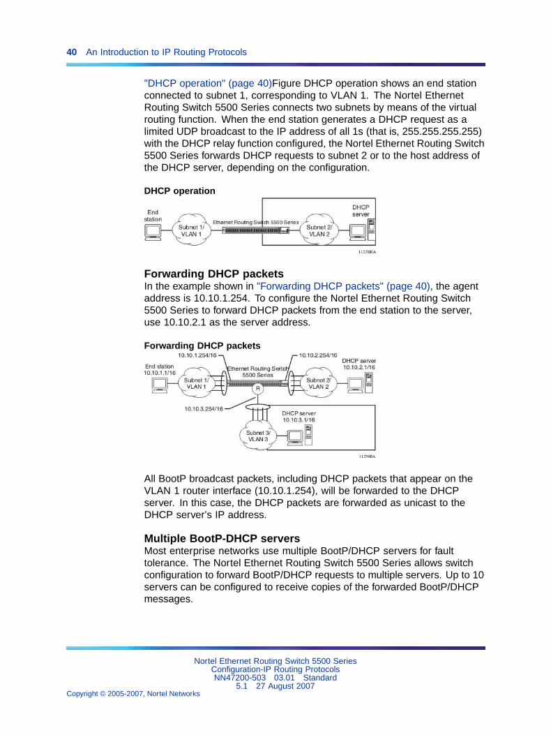
"DHCP operation" (page 40)Figure DHCP operation shows an end stationconnected to subnet 1, corresponding to VLAN 1. The Nortel EthernetRouting Switch 5500 Series connects two subnets by means of the virtualrouting function. When the end station generates a DHCP request as alimited UDP broadcast to the IP address of all 1s (that is, 255.255.255.255)with the DHCP relay function configured, the Nortel Ethernet Routing Switch5500 Series forwards DHCP requests to subnet 2 or to the host address ofthe DHCP server, depending on the configuration.
DHCP operation
Forwarding DHCP packetsIn the example shown in "Forwarding DHCP packets" (page 40), the agentaddress is 10.10.1.254. To configure the Nortel Ethernet Routing Switch5500 Series to forward DHCP packets from the end station to the server,use 10.10.2.1 as the server address.
Forwarding DHCP packets
All BootP broadcast packets, including DHCP packets that appear on theVLAN 1 router interface (10.10.1.254), will be forwarded to the DHCPserver. In this case, the DHCP packets are forwarded as unicast to theDHCP server’s IP address.
Multiple BootP-DHCP serversMost enterprise networks use multiple BootP/DHCP servers for faulttolerance. The Nortel Ethernet Routing Switch 5500 Series allows switchconfiguration to forward BootP/DHCP requests to multiple servers. Up to 10servers can be configured to receive copies of the forwarded BootP/DHCPmessages.
Nortel Ethernet Routing Switch 5500 SeriesConfiguration-IP Routing ProtocolsNN47200-503 03.01 Standard
5.1 27 August 2007Copyright © 2005-2007, Nortel Networks
.

IP routing 41
If a DHCP client is connected to a routable interface, to configure DHCPrequests to be sent to up to 512 different routable interfaces or 512 differentserver IP addresses, enable DHCP on the client (agent address) and thenenable DHCP from the client to each of the interfaces or IP addresses(server addresses).
In the example shown in "Multiple BootP/DHCP servers" (page 41), twoDHCP servers are located on two different subnets. To configure theNortel Ethernet Routing Switch 5500 Series to forward the copies of theBootP/DHCP packets from the end station to both servers, specify the switch(10.10.1.254) as the agent address. Then enable DHCP to each of theDHCP servers by entering 10.10.2.1 and 10.10.3.1 as the server addresses.
Multiple BootP/DHCP servers
Setting DHCPTo set DHCP, take the following steps:
Step Action
1 Enable IP routing on the Nortel Ethernet Routing Switch 5500 Seriesand on the target VLAN interface.
2 Enable DHCP globally.
Note: DHCP is enabled by default.
3 Set the DHCP forwarding paths, using the VLAN IP as the startingpoint, or agent IP.
4 Set the mode for each DHCP forwarding path.
5 Enable DHCP for the specific VLAN.
6 Enable the DHCP broadcast message for the specific VLAN.
—End—
Nortel Ethernet Routing Switch 5500 SeriesConfiguration-IP Routing ProtocolsNN47200-503 03.01 Standard
5.1 27 August 2007Copyright © 2005-2007, Nortel Networks
.
42 An Introduction to IP Routing Protocols
Any of the Nortel Ethernet Routing Switch 5500 Series switch managementsystems can be used to set DHCP.
DHCP relayDHCP (Dynamic Host Configuration Protocol) is a mechanism to assignnetwork IP addresses to clients who request an address. It is built on topof the existing BOOTP protocol and can be specified for DHCP, BOOTP,or both.
The DHCP relay feature relays client requests to DHCP servers on differentL3 VLANs. It also relays server replies back to the clients.
DHCP relay can be configured through Command Line Interface or JavaDevice Manager. DHCP can only be configured on the base unit fromCLI, like all L3 commands. There are three parts in the DHCP relayconfigurations. They are:
• global DHCP enable/disable
• interface configurations
• forward path configurations
To relay DHCP messages, two VLANs must be created and IP addressesassigned to them. The client and server must reside on different L3 VLANSto use DHCP relay. IP routing and global DHCP relay must be enabledon both the client as well as server.
Note: The DHCP Relay feature shares resources with QoS. If theDHCP Relay feature is enabled, a QoS policy with a precedence of 11cannot be installed.
For further information on QoS policies refer to Nortel Ethernet RoutingSwitch 5500 Series Configuration - Quality of Service (Part NumberNN47200-504).
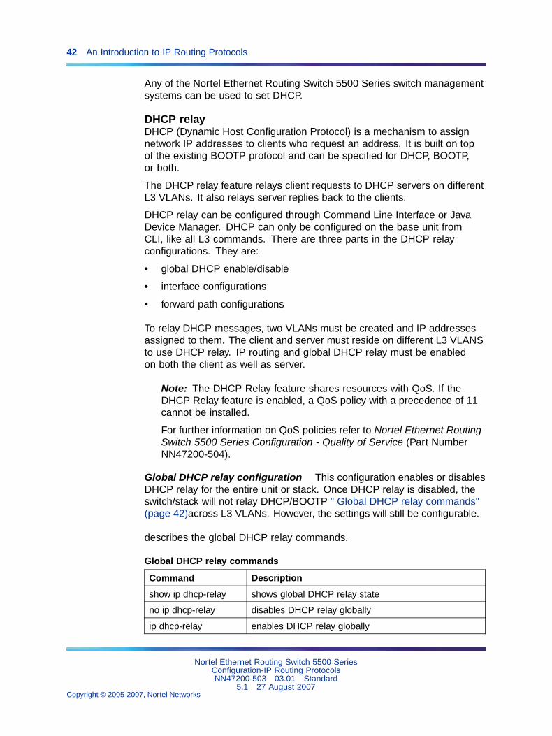
Global DHCP relay configuration This configuration enables or disablesDHCP relay for the entire unit or stack. Once DHCP relay is disabled, theswitch/stack will not relay DHCP/BOOTP " Global DHCP relay commands"(page 42)across L3 VLANs. However, the settings will still be configurable.
describes the global DHCP relay commands.
Global DHCP relay commands
Command Description
show ip dhcp-relay shows global DHCP relay state
no ip dhcp-relay disables DHCP relay globally
ip dhcp-relay enables DHCP relay globally
Nortel Ethernet Routing Switch 5500 SeriesConfiguration-IP Routing ProtocolsNN47200-503 03.01 Standard
5.1 27 August 2007Copyright © 2005-2007, Nortel Networks
.
IP routing 43
These commands must be executed in the Global Configuration commandmode.
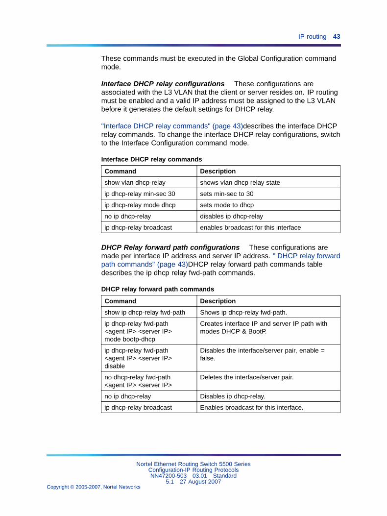
Interface DHCP relay configurations These configurations areassociated with the L3 VLAN that the client or server resides on. IP routingmust be enabled and a valid IP address must be assigned to the L3 VLANbefore it generates the default settings for DHCP relay.
"Interface DHCP relay commands" (page 43)describes the interface DHCPrelay commands. To change the interface DHCP relay configurations, switchto the Interface Configuration command mode.
Interface DHCP relay commands
Command Description
show vlan dhcp-relay shows vlan dhcp relay state
ip dhcp-relay min-sec 30 sets min-sec to 30
ip dhcp-relay mode dhcp sets mode to dhcp
no ip dhcp-relay disables ip dhcp-relay
ip dhcp-relay broadcast enables broadcast for this interface
DHCP Relay forward path configurations These configurations aremade per interface IP address and server IP address. " DHCP relay forwardpath commands" (page 43)DHCP relay forward path commands tabledescribes the ip dhcp relay fwd-path commands.
DHCP relay forward path commands
Command Description
show ip dhcp-relay fwd-path Shows ip dhcp-relay fwd-path.
ip dhcp-relay fwd-path<agent IP> <server IP>mode bootp-dhcp
Creates interface IP and server IP path withmodes DHCP & BootP.
ip dhcp-relay fwd-path<agent IP> <server IP>disable
Disables the interface/server pair, enable =false.
no dhcp-relay fwd-path<agent IP> <server IP>
Deletes the interface/server pair.
no ip dhcp-relay Disables ip dhcp-relay.
ip dhcp-relay broadcast Enables broadcast for this interface.
Nortel Ethernet Routing Switch 5500 SeriesConfiguration-IP Routing ProtocolsNN47200-503 03.01 Standard
5.1 27 August 2007Copyright © 2005-2007, Nortel Networks
.
44 An Introduction to IP Routing Protocols
DHCP relay uses a hardware resource that is shared by switch Quality ofService applications. When DHCP relay is enabled globally, the Qualityof Service filter manager will not be able to use precedence 11 forconfigurations. For the filter manager to be able to use this resource, DHCPrelay must be disabled for the entire unit or stack.
Avoiding duplicate IP addressesThe Nortel Ethernet Routing Switch 5500 Series has built-in safeguards toavoid issuing duplicate IP addresses, because the switch functions as astack as well as a stand-alone system. These safeguards apply to stackconfiguration changes (for example, when a stack is forming or after a unitis removed from a stack).
The system allows the use of an existing IP address under the followingconditions:
• When a unit leaves a stack:
— If the unit was the acting Base Unit (BU) of the stack and the stackconsisted of only two units.
— If the IP blocking mode in the stack was set to none.
• When a unit boots up:
— If the unit was never in a stack.
— If IP blocking was manually turned off prior to the current boot.
— If the unit was the designated Base Unit (BU); that is, selected byhardware switch on the unit, either on the back or on the UI buttonon the front; and the stack consisted of only two units.
— If the IP blocking mode was set to none.
If the desired switch IP address is blocked by the system, then the addressmust be configured manually in the command line interface.
Automatic router ID changeIf a unit leaves the stack and becomes standalone (when the stack disjoins),the router ID is automatically changed to its default value. This preventsrouter ID duplication in the OSPF routing domain.
Prerequisites: IP blocking must be turned off (set to none) and OSPFmust be globally enabled.
TIP: The change in router ID is temporary (not saved in non-volatile randomaccess memory) and, upon reset, the router ID is restored.
Nortel Ethernet Routing Switch 5500 SeriesConfiguration-IP Routing ProtocolsNN47200-503 03.01 Standard
5.1 27 August 2007Copyright © 2005-2007, Nortel Networks
.
IP routing 45
IP blockingIP Blocking is a Layer 3 feature of the Nortel Ethernet Routing Switch5500 Series that provides built-in safeguards for the usage of duplicate IPaddresses in a stacked environment. IP Blocking is used whenever a unitleaves a stack or is rebooting inside the context of a stack. Depending onthe setting in use, Layer 3 functionality is either continued or blocked bythis feature.
IP Blocking can exist in either a none or full condition. When IP Blockingis set to none, duplicate IP addresses are permitted in the stackunconditionally. When the full condition is set, duplicate IP addresses areblocked in the stack unconditionally.
In a stack environment, Nortel recommends that IP blocking mode none beused in a stack of 2 units. In such a stack environment and IP blockingmode combination, the following functional characteristics can be expected:
• If the stack base unit becomes non-operational the following will occur:
— Layer 3 functionality will continue to run on the non-base unit.
— Dynamic routing protocols still run on the non-base unit.
• If the stack non-base unit becomes non-operational the following willoccur:
— Layer 3 functionality will continue to run on the base unit.
— Dynamic routing protocols run on the base unit.
A disadvantage of this configuration is that if the non-operational unit doesnot rejoin the stack, address duplication will occur.
In stack environments of more than 2 units, Nortel recommends using IPblocking mode full. In such a stack environment and IP blocking modecombination, the following functional characteristics can be expected:
• If the stack base unit becomes non-operational the following will occur:
— The temporary base unit takes over base unit duties.
— The temporary base unit runs the Layer 3 and DRP functionality.
— The takeover of the temporary base unit will cause the MACaddresses of the Layer 3 interfaces to change and the MACaddresses from the temporary base unit MAC address pool areused. This may cause a minor disruption in routing traffic. Tofacilitate quick failover in this instance, gratuitous ARP messages aresent out for each interface for 5 minutes at 15 second intervals.
• If a stack non-base unit becomes non-operational the following willoccur:
Nortel Ethernet Routing Switch 5500 SeriesConfiguration-IP Routing ProtocolsNN47200-503 03.01 Standard
5.1 27 August 2007Copyright © 2005-2007, Nortel Networks
.
46 An Introduction to IP Routing Protocols
— The stack will continue to run normally with the base unit controllingLayer 3 and DRP functionality.
— If the non-operational non-base unit does not rejoin the stack, noLayer 3 or DRP functionality will run on it.
IGMP snoopingThe Nortel Ethernet Routing Switch 5500 Series can sense Internet GroupManagement Protocol (IGMP) host membership reports from attachedstations and use this information to set up a dedicated path between therequesting station and a local IP Multicast router. After the pathway isestablished, the Nortel Ethernet Routing Switch 5500 Series switch blocksthe IP Multicast stream from exiting any other port that does not connect toanother host member, thus conserving bandwidth. The following sectiondescribes how Nortel Ethernet Routing Switch 5500 Series switches providethe same benefit as IP Multicast routers, but in the local area.
IGMP is used by IP Multicast routers to learn about the existence of hostgroup members on their directly attached subnets (see RFC 2236). The IPMulticast routers get this information by broadcasting IGMP queries andlistening for IP hosts reporting their host group memberships. This processis used to set up a client/server relationship between an IP Multicast sourcethat provides the data streams and the clients that want to receive the data.
By default, unknown multicast traffic is flooded to all ports in a VLAN. Insituations in which there is a multicast transmitter that is not doing IGMPand there are no multicast receivers, the traffic transmitted by the transmitteris flooded.
The CLI commands for IGMP allow the sending of all unknown multicasttraffic to IGMP static router ports only. This traffic will not be forwarded todynamically discovered m-router ports. If it is desirable to forward unknownunicast traffic to certain ports only, those ports can be set as static m-routerports.
• When disabled, the Nortel Ethernet Routing Switch 5500 Series switchtreats unknown multicast traffic as it does broadcast traffic (flood). Thisis the default behavior.
• User settings for the Unknown Multicast No Flood feature is stored inNVRAM. In a stack, if settings on different units differ, the Base Unitsetting will take precedence. This feature can be enabled or disabledat any time.
• Nortel Networks recommends this feature be enabled when IGMPsnooping is enabled.
Nortel Ethernet Routing Switch 5500 SeriesConfiguration-IP Routing ProtocolsNN47200-503 03.01 Standard
5.1 27 August 2007Copyright © 2005-2007, Nortel Networks
.
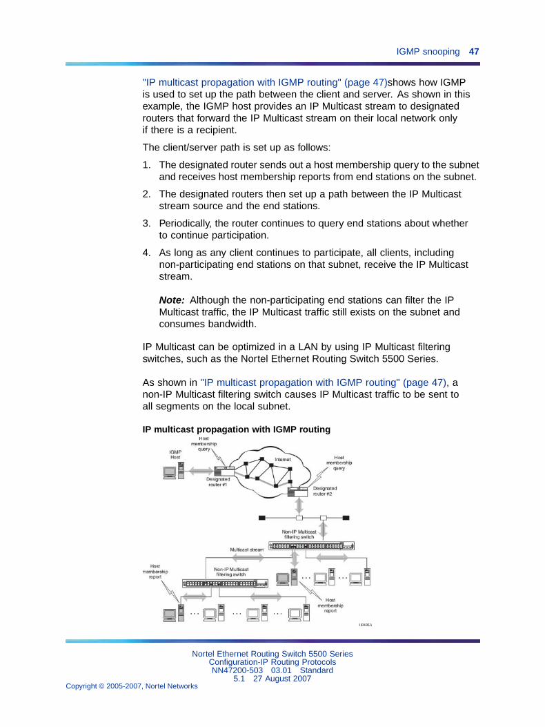
IGMP snooping 47
"IP multicast propagation with IGMP routing" (page 47)shows how IGMPis used to set up the path between the client and server. As shown in thisexample, the IGMP host provides an IP Multicast stream to designatedrouters that forward the IP Multicast stream on their local network onlyif there is a recipient.
The client/server path is set up as follows:
1. The designated router sends out a host membership query to the subnetand receives host membership reports from end stations on the subnet.
2. The designated routers then set up a path between the IP Multicaststream source and the end stations.
3. Periodically, the router continues to query end stations about whetherto continue participation.
4. As long as any client continues to participate, all clients, includingnon-participating end stations on that subnet, receive the IP Multicaststream.
Note: Although the non-participating end stations can filter the IPMulticast traffic, the IP Multicast traffic still exists on the subnet andconsumes bandwidth.
IP Multicast can be optimized in a LAN by using IP Multicast filteringswitches, such as the Nortel Ethernet Routing Switch 5500 Series.
As shown in "IP multicast propagation with IGMP routing" (page 47), anon-IP Multicast filtering switch causes IP Multicast traffic to be sent toall segments on the local subnet.
IP multicast propagation with IGMP routing
Nortel Ethernet Routing Switch 5500 SeriesConfiguration-IP Routing ProtocolsNN47200-503 03.01 Standard
5.1 27 August 2007Copyright © 2005-2007, Nortel Networks
.

48 An Introduction to IP Routing Protocols
The Nortel Ethernet Routing Switch 5500 Series can automatically set up IPMulticast filters so the IP Multicast traffic is only directed to the participatingend nodes (see ).
In , "5500 Series switch filtering IP multicast streams (1 of 2)" (page48)switches S1 to S4 represent a LAN connected to an IP Multicast router.The router periodically sends Host Membership Queries to the LAN andlistens for a response from end stations. All of the clients connected toswitches S1 to S4 are aware of the queries from the router.
One client, connected to S2, responds with a host membership report.Switch S2 intercepts the report from that port, and generates a proxy reportto its upstream neighbor, S1. Also, two clients connected to S4 respondwith host membership reports, causing S4 to intercept the reports and togenerate a consolidated proxy report to its upstream neighbor, S1.
5500 Series switch filtering IP multicast streams (1 of 2)
Switch S1 treats the consolidated proxy reports from S2 and S4 as ifthey were reports from any client connected to its ports, and generates aconsolidated proxy report to the designated router. In this way, the routerreceives a single consolidated report from that entire subnet.
After the switches learn which ports are requesting access to the IPMulticast stream, all other ports not responding to the queries are blockedfrom receiving the IP Multicast ("5500 Series switch filtering IP multicaststreams (2 of 2)" (page 49)).
Nortel Ethernet Routing Switch 5500 SeriesConfiguration-IP Routing ProtocolsNN47200-503 03.01 Standard
5.1 27 August 2007Copyright © 2005-2007, Nortel Networks
.

IGMP snooping 49
5500 Series switch filtering IP multicast streams (2 of 2)
The consolidated proxy report generated by the switch remains transparentto Layer 3 of the International Standardization Organization, Open SystemsInterconnection (ISO/OSI) model. (The switch IP address and MAC addressare not part of proxy report generation.) The last reporting IGMP groupmember in each VLAN represents all of the hosts in that VLAN and IGMPgroup.
IGMP snooping configuration rulesThe IGMP snooping feature operates according to specific configurationrules. When configuring the switch for IGMP snooping, consider thefollowing rules that determine how the configuration reacts in any networktopology:
• There is a maximum of 240 groups on the Nortel Ethernet RoutingSwitch 5500 Series.
• A port that is configured for port mirroring cannot be configured asa static router port.
• If a MultiLink Trunk member is configured as a static router port, all ofthe MultiLink trunk members are configured as static router ports. Also,if a static router port is removed, and it is a MultiLink Trunk member, allMultiLink trunk members are removed as static router port members,automatically.
• Static router ports must be port members of at least one VLAN.
• The IGMP snooping feature is not STP dependent.
• The IGMP snooping feature is not Rate Limiting dependent.
Nortel Ethernet Routing Switch 5500 SeriesConfiguration-IP Routing ProtocolsNN47200-503 03.01 Standard
5.1 27 August 2007Copyright © 2005-2007, Nortel Networks
.
50 An Introduction to IP Routing Protocols
• The snooping field must be enabled for the proxy field to have anyvalid meaning.
• Static router ports are configured per VLAN and per IGMP Version.
Note: Because IGMP snooping is set up per VLAN, all IGMP changesare implemented according to the VLAN configuration for the specifiedports.
Nortel Ethernet Routing Switch 5500 SeriesConfiguration-IP Routing ProtocolsNN47200-503 03.01 Standard
5.1 27 August 2007Copyright © 2005-2007, Nortel Networks
.
51
IP Routing Configuration andManagement
This chapter describes the configuration and management of IP routing inthe Nortel Ethernet Routing Switch 5500 Series. IP Routing configurationis accomplished through the Command Line Interface (CLI), Web-basedManagement Interface, or the Java Device Manager (JDM).
This chapter contains the following topics:
• "IP routing initial configuration" (page 51)
• "IP routing configuration examples" (page 120)
• "IP routing configuration using the Java Device Manager" (page 206)
IP routing initial configurationThis section provides step by step instructions for the initial configuration ofthe IP routing protocols supported by the Nortel Ethernet Routing Switch5500 Series. For conceptual information about IP routing topics coveredin this section, refer to "An Introduction to IP Routing Protocols" (page 13).This section contains the following topics:
• "Global IP routing configuration" (page 51)
• "Open Shortest Path First (OSPF) initial configuration" (page 52)
This chapter also contains in-depth configuration examples that can aid inthe advanced configuration of the switch. Refer to "IP routing configurationexamples" (page 120)for these advanced examples.
Global IP routing configurationBefore IP routing configuration can take place, IP routing must be globallyenabled on the switch. Use the set of commands outlined below to enter theGlobal Configuration mode of the switch and enable IP routing.
5530-24TFD# enable5530-24TFD# config terminal5530-24TFD(config)# ip routing
Nortel Ethernet Routing Switch 5500 SeriesConfiguration-IP Routing ProtocolsNN47200-503 03.01 Standard
5.1 27 August 2007Copyright © 2005-2007, Nortel Networks
.
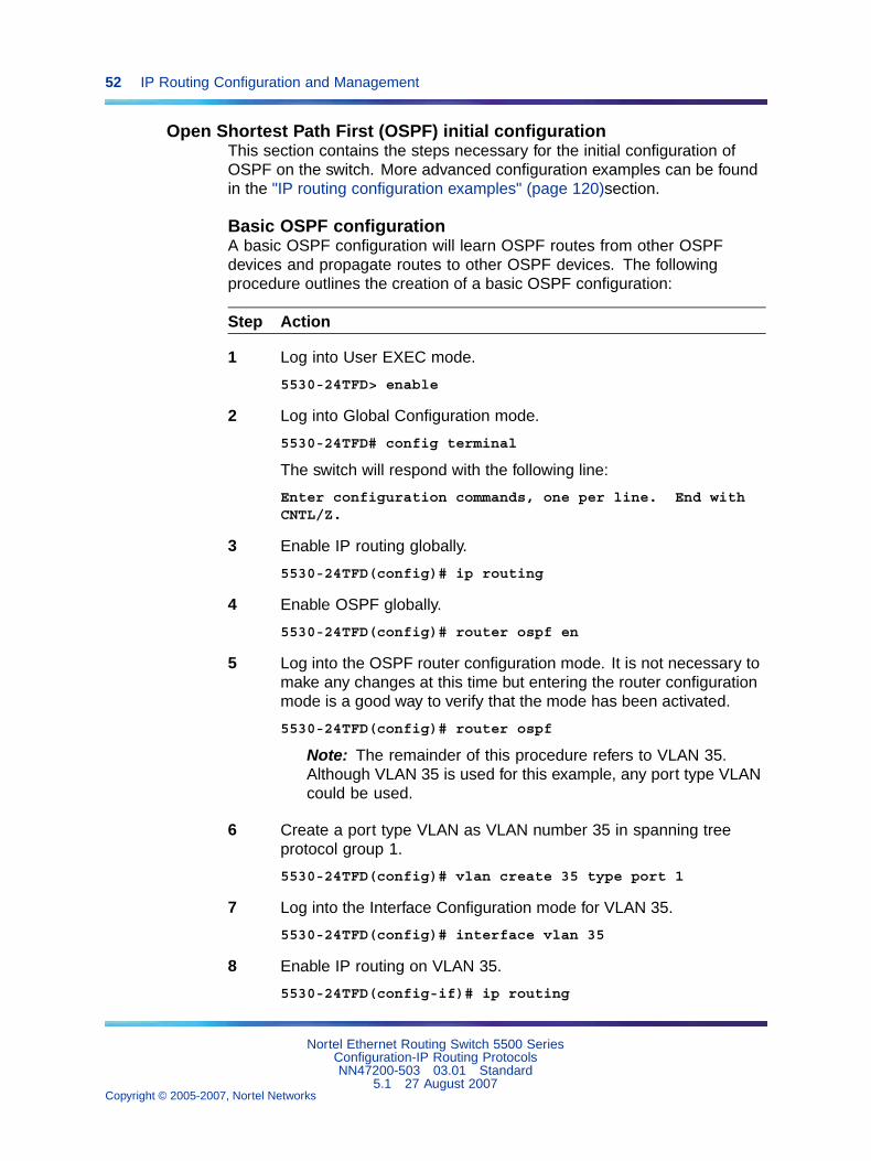
52 IP Routing Configuration and Management
Open Shortest Path First (OSPF) initial configurationThis section contains the steps necessary for the initial configuration ofOSPF on the switch. More advanced configuration examples can be foundin the "IP routing configuration examples" (page 120)section.
Basic OSPF configurationA basic OSPF configuration will learn OSPF routes from other OSPFdevices and propagate routes to other OSPF devices. The followingprocedure outlines the creation of a basic OSPF configuration:
Step Action
1 Log into User EXEC mode.
5530-24TFD> enable
2 Log into Global Configuration mode.
5530-24TFD# config terminal
The switch will respond with the following line:
Enter configuration commands, one per line. End withCNTL/Z.
3 Enable IP routing globally.
5530-24TFD(config)# ip routing
4 Enable OSPF globally.
5530-24TFD(config)# router ospf en
5 Log into the OSPF router configuration mode. It is not necessary tomake any changes at this time but entering the router configurationmode is a good way to verify that the mode has been activated.
5530-24TFD(config)# router ospf
Note: The remainder of this procedure refers to VLAN 35.Although VLAN 35 is used for this example, any port type VLANcould be used.
6 Create a port type VLAN as VLAN number 35 in spanning treeprotocol group 1.
5530-24TFD(config)# vlan create 35 type port 1
7 Log into the Interface Configuration mode for VLAN 35.
5530-24TFD(config)# interface vlan 35
8 Enable IP routing on VLAN 35.
5530-24TFD(config-if)# ip routing
Nortel Ethernet Routing Switch 5500 SeriesConfiguration-IP Routing ProtocolsNN47200-503 03.01 Standard
5.1 27 August 2007Copyright © 2005-2007, Nortel Networks
.
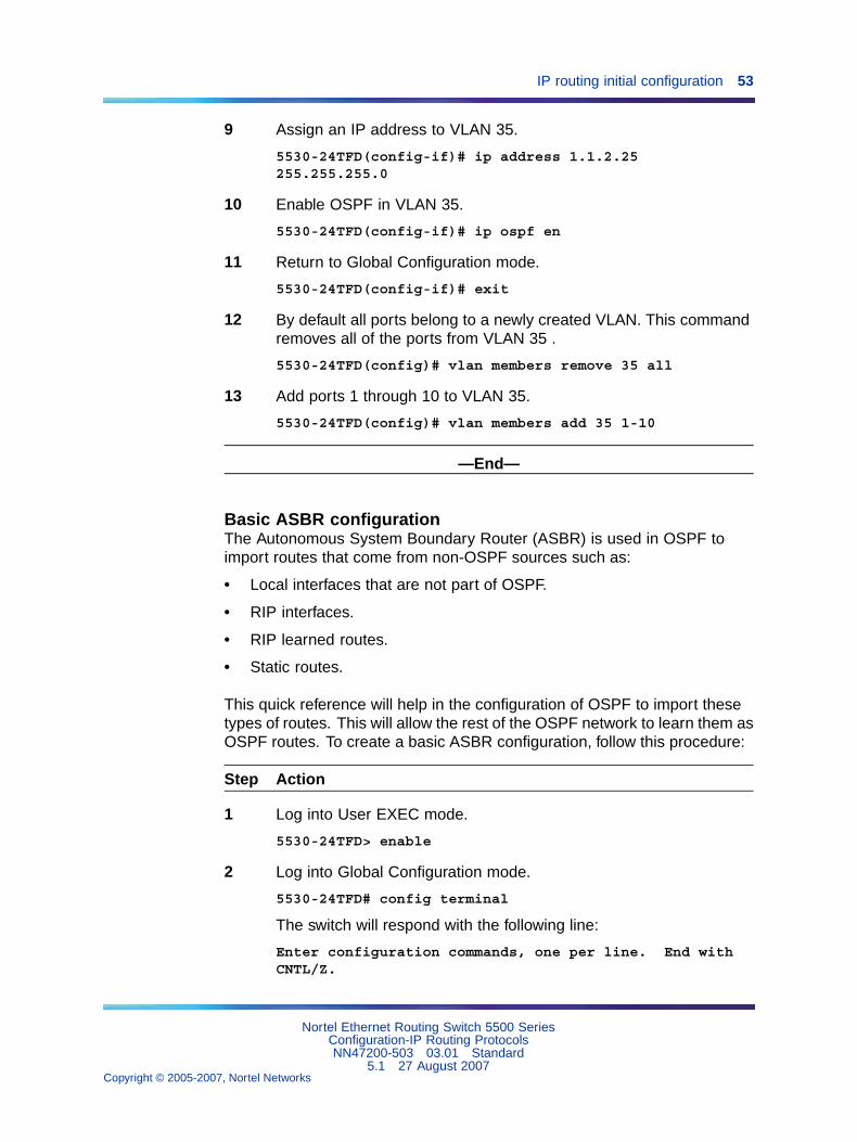
IP routing initial configuration 53
9 Assign an IP address to VLAN 35.
5530-24TFD(config-if)# ip address 1.1.2.25255.255.255.0
10 Enable OSPF in VLAN 35.
5530-24TFD(config-if)# ip ospf en
11 Return to Global Configuration mode.
5530-24TFD(config-if)# exit
12 By default all ports belong to a newly created VLAN. This commandremoves all of the ports from VLAN 35 .
5530-24TFD(config)# vlan members remove 35 all
13 Add ports 1 through 10 to VLAN 35.
5530-24TFD(config)# vlan members add 35 1-10
—End—
Basic ASBR configurationThe Autonomous System Boundary Router (ASBR) is used in OSPF toimport routes that come from non-OSPF sources such as:
• Local interfaces that are not part of OSPF.
• RIP interfaces.
• RIP learned routes.
• Static routes.
This quick reference will help in the configuration of OSPF to import thesetypes of routes. This will allow the rest of the OSPF network to learn them asOSPF routes. To create a basic ASBR configuration, follow this procedure:
Step Action
1 Log into User EXEC mode.
5530-24TFD> enable
2 Log into Global Configuration mode.
5530-24TFD# config terminal
The switch will respond with the following line:
Enter configuration commands, one per line. End withCNTL/Z.
Nortel Ethernet Routing Switch 5500 SeriesConfiguration-IP Routing ProtocolsNN47200-503 03.01 Standard
5.1 27 August 2007Copyright © 2005-2007, Nortel Networks
.
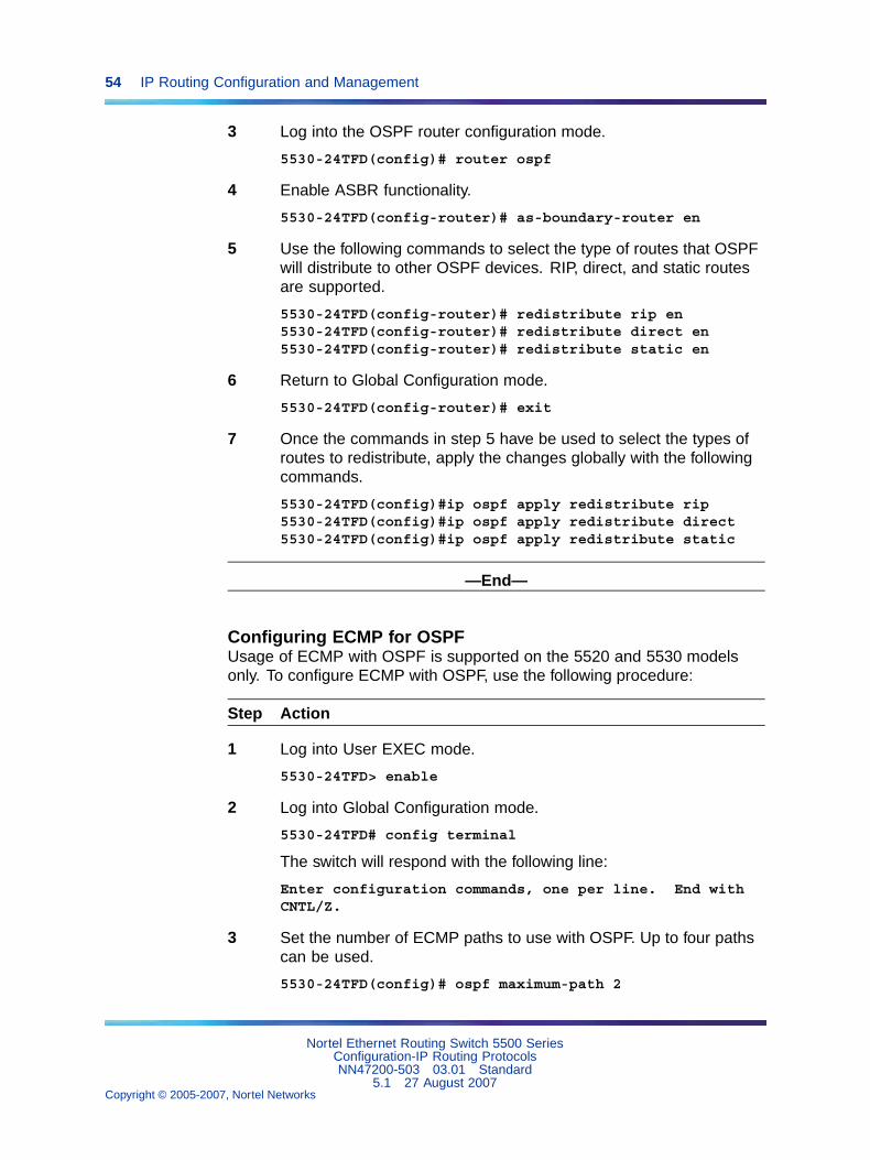
54 IP Routing Configuration and Management
3 Log into the OSPF router configuration mode.
5530-24TFD(config)# router ospf
4 Enable ASBR functionality.
5530-24TFD(config-router)# as-boundary-router en
5 Use the following commands to select the type of routes that OSPFwill distribute to other OSPF devices. RIP, direct, and static routesare supported.
5530-24TFD(config-router)# redistribute rip en5530-24TFD(config-router)# redistribute direct en5530-24TFD(config-router)# redistribute static en
6 Return to Global Configuration mode.
5530-24TFD(config-router)# exit
7 Once the commands in step 5 have be used to select the types ofroutes to redistribute, apply the changes globally with the followingcommands.
5530-24TFD(config)#ip ospf apply redistribute rip5530-24TFD(config)#ip ospf apply redistribute direct5530-24TFD(config)#ip ospf apply redistribute static
—End—
Configuring ECMP for OSPFUsage of ECMP with OSPF is supported on the 5520 and 5530 modelsonly. To configure ECMP with OSPF, use the following procedure:
Step Action
1 Log into User EXEC mode.
5530-24TFD> enable
2 Log into Global Configuration mode.
5530-24TFD# config terminal
The switch will respond with the following line:
Enter configuration commands, one per line. End withCNTL/Z.
3 Set the number of ECMP paths to use with OSPF. Up to four pathscan be used.
5530-24TFD(config)# ospf maximum-path 2
Nortel Ethernet Routing Switch 5500 SeriesConfiguration-IP Routing ProtocolsNN47200-503 03.01 Standard
5.1 27 August 2007Copyright © 2005-2007, Nortel Networks
.
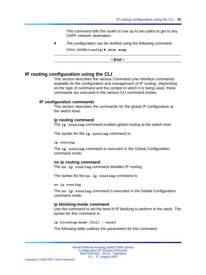
IP routing configuration using the CLI 55
This command tells the router to use up to two paths to get to anyOSPF network destination.
4 The configuration can be verified using the following command.
5530-24TFD(config)# show ecmp
—End—
IP routing configuration using the CLIThis section describes the various Command Line Interface commandsavailable for the configuration and management of IP routing. Dependingon the type of command and the context in which it is being used, thesecommands are executed in the various CLI command modes.
IP configuration commandsThis section describes the commands for the global IP configuration atthe switch level.
ip routing commandThe ip routing command enables global routing at the switch level.
The syntax for the ip routing command is:
ip routing
The ip routing command is executed in the Global Configurationcommand mode.
no ip routing commandThe no ip routing command disables IP routing.
The syntax for the no ip routing command is:
no ip routing
The no ip routing command is executed in the Global Configurationcommand mode.
ip blocking-mode commandUse this command to set the level of IP blocking to perform in the stack. Thesyntax for this command is:
ip blocking-mode {full | none}
The following table outlines the parameters for this command.
Nortel Ethernet Routing Switch 5500 SeriesConfiguration-IP Routing ProtocolsNN47200-503 03.01 Standard
5.1 27 August 2007Copyright © 2005-2007, Nortel Networks
.
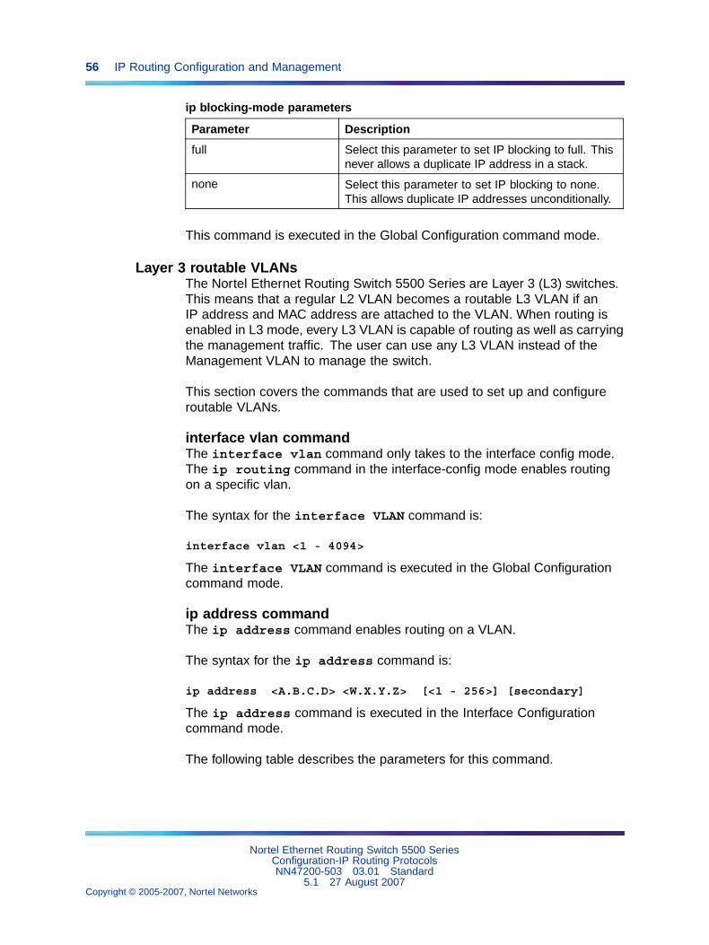
56 IP Routing Configuration and Management
ip blocking-mode parameters
Parameter Description
full Select this parameter to set IP blocking to full. Thisnever allows a duplicate IP address in a stack.
none Select this parameter to set IP blocking to none.This allows duplicate IP addresses unconditionally.
This command is executed in the Global Configuration command mode.
Layer 3 routable VLANsThe Nortel Ethernet Routing Switch 5500 Series are Layer 3 (L3) switches.This means that a regular L2 VLAN becomes a routable L3 VLAN if anIP address and MAC address are attached to the VLAN. When routing isenabled in L3 mode, every L3 VLAN is capable of routing as well as carryingthe management traffic. The user can use any L3 VLAN instead of theManagement VLAN to manage the switch.
This section covers the commands that are used to set up and configureroutable VLANs.
interface vlan commandThe interface vlan command only takes to the interface config mode.The ip routing command in the interface-config mode enables routingon a specific vlan.
The syntax for the interface VLAN command is:
interface vlan <1 - 4094>
The interface VLAN command is executed in the Global Configurationcommand mode.
ip address commandThe ip address command enables routing on a VLAN.
The syntax for the ip address command is:
ip address <A.B.C.D> <W.X.Y.Z> [<1 - 256>] [secondary]
The ip address command is executed in the Interface Configurationcommand mode.
The following table describes the parameters for this command.
Nortel Ethernet Routing Switch 5500 SeriesConfiguration-IP Routing ProtocolsNN47200-503 03.01 Standard
5.1 27 August 2007Copyright © 2005-2007, Nortel Networks
.
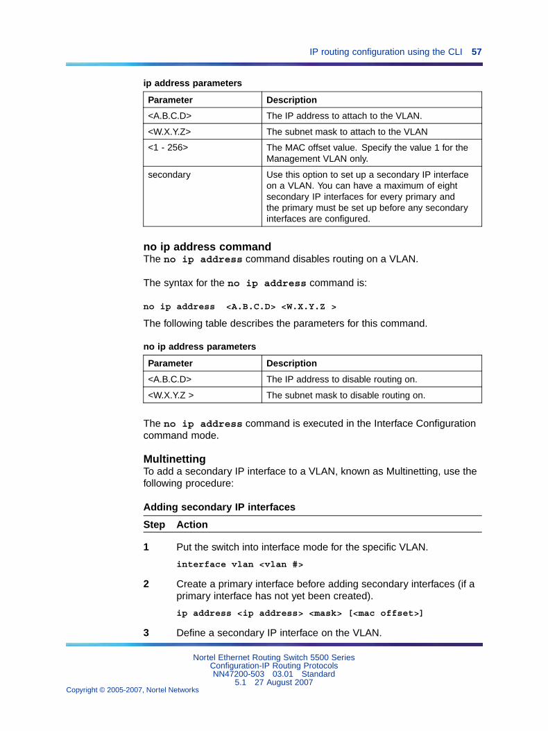
IP routing configuration using the CLI 57
ip address parameters
Parameter Description
<A.B.C.D> The IP address to attach to the VLAN.
<W.X.Y.Z> The subnet mask to attach to the VLAN
<1 - 256> The MAC offset value. Specify the value 1 for theManagement VLAN only.
secondary Use this option to set up a secondary IP interfaceon a VLAN. You can have a maximum of eightsecondary IP interfaces for every primary andthe primary must be set up before any secondaryinterfaces are configured.
no ip address commandThe no ip address command disables routing on a VLAN.
The syntax for the no ip address command is:
no ip address <A.B.C.D> <W.X.Y.Z >
The following table describes the parameters for this command.
no ip address parameters
Parameter Description
<A.B.C.D> The IP address to disable routing on.
<W.X.Y.Z > The subnet mask to disable routing on.
The no ip address command is executed in the Interface Configurationcommand mode.
MultinettingTo add a secondary IP interface to a VLAN, known as Multinetting, use thefollowing procedure:
Adding secondary IP interfaces
Step Action
1 Put the switch into interface mode for the specific VLAN.
interface vlan <vlan #>
2 Create a primary interface before adding secondary interfaces (if aprimary interface has not yet been created).
ip address <ip address> <mask> [<mac offset>]
3 Define a secondary IP interface on the VLAN.
Nortel Ethernet Routing Switch 5500 SeriesConfiguration-IP Routing ProtocolsNN47200-503 03.01 Standard
5.1 27 August 2007Copyright © 2005-2007, Nortel Networks
.
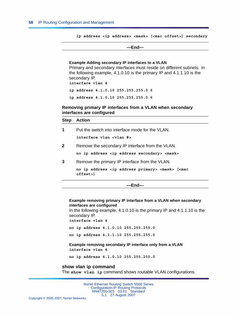
58 IP Routing Configuration and Management
ip address <ip address> <mask> [<mac offset>] secondary
—End—
Example Adding secondary IP interfaces to a VLANPrimary and secondary interfaces must reside on different subnets. Inthe following example, 4.1.0.10 is the primary IP and 4.1.1.10 is thesecondary IP.interface vlan 4
ip address 4.1.0.10 255.255.255.0 6
ip address 4.1.0.10 255.255.255.0 6
Removing primary IP interfaces from a VLAN when secondaryinterfaces are configured
Step Action
1 Put the switch into interface mode for the VLAN.
interface vlan <vlan #>
2 Remove the secondary IP interface from the VLAN.
no ip address <ip address secondary> <mask>
3 Remove the primary IP interface from the VLAN.
no ip address <ip address primary> <mask> [<macoffset>]
—End—
Example removing primary IP interface from a VLAN when secondaryinterfaces are configuredIn the following example, 4.1.0.10 is the primary IP and 4.1.1.10 is thesecondary IP.interface vlan 4
no ip address 4.1.0.10 255.255.255.0
no ip address 4.1.1.10 255.255.255.0
Example removing secondary IP interface only from a VLANinterface vlan 4
no ip address 4.1.0.10 255.255.255.0
show vlan ip commandThe show vlan ip command shows routable VLAN configurations.
Nortel Ethernet Routing Switch 5500 SeriesConfiguration-IP Routing ProtocolsNN47200-503 03.01 Standard
5.1 27 August 2007Copyright © 2005-2007, Nortel Networks
.
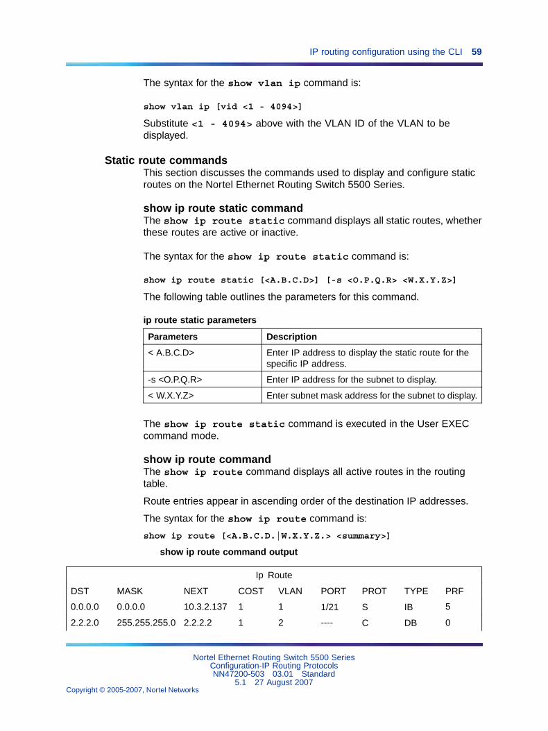
IP routing configuration using the CLI 59
The syntax for the show vlan ip command is:
show vlan ip [vid <1 - 4094>]
Substitute <1 - 4094> above with the VLAN ID of the VLAN to bedisplayed.
Static route commandsThis section discusses the commands used to display and configure staticroutes on the Nortel Ethernet Routing Switch 5500 Series.
show ip route static commandThe show ip route static command displays all static routes, whetherthese routes are active or inactive.
The syntax for the show ip route static command is:
show ip route static [<A.B.C.D>] [-s <O.P.Q.R> <W.X.Y.Z>]
The following table outlines the parameters for this command.
ip route static parameters
Parameters Description
< A.B.C.D> Enter IP address to display the static route for thespecific IP address.
-s <O.P.Q.R> Enter IP address for the subnet to display.
< W.X.Y.Z> Enter subnet mask address for the subnet to display.
The show ip route static command is executed in the User EXECcommand mode.
show ip route commandThe show ip route command displays all active routes in the routingtable.
Route entries appear in ascending order of the destination IP addresses.
The syntax for the show ip route command is:
show ip route [<A.B.C.D.|W.X.Y.Z.> <summary>]
show ip route command output
Ip Route
DST MASK NEXT COST VLAN PORT PROT TYPE PRF
0.0.0.0 0.0.0.0 10.3.2.137 1 1 1/21 S IB 5
2.2.2.0 255.255.255.0 2.2.2.2 1 2 ---- C DB 0
Nortel Ethernet Routing Switch 5500 SeriesConfiguration-IP Routing ProtocolsNN47200-503 03.01 Standard
5.1 27 August 2007Copyright © 2005-2007, Nortel Networks
.
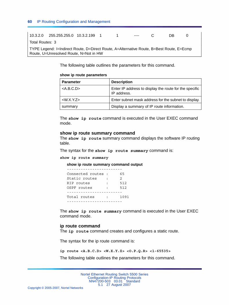
60 IP Routing Configuration and Management
10.3.2.0 255.255.255.0 10.3.2.199 1 1 ---- C DB 0
Total Routes: 3
TYPE Legend: I=Indirect Route, D=Direct Route, A=Alternative Route, B=Best Route, E=EcmpRoute, U=Unresolved Route, N=Not in HW
The following table outlines the parameters for this command.
show ip route parameters
Parameter Description
<A.B.C.D> Enter IP address to display the route for the specificIP address.
<W.X.Y.Z> Enter subnet mask address for the subnet to display.
summary Display a summary of IP route information.
The show ip route command is executed in the User EXEC commandmode.
show ip route summary commandThe show ip route summary command displays the software IP routingtable.
The syntax for the show ip route summary command is:
show ip route summary
show ip route summary command output------------------------Connected routes : 65Static routes : 2RIP routes : 512OSPF routes : 512------------------------Total routes : 1091------------------------
The show ip route summary command is executed in the User EXECcommand mode.
ip route commandThe ip route command creates and configures a static route.
The syntax for the ip route command is:
ip route <A.B.C.D> <W.X.Y.Z> <O.P.Q.R> <1-65535>
The following table outlines the parameters for this command.
Nortel Ethernet Routing Switch 5500 SeriesConfiguration-IP Routing ProtocolsNN47200-503 03.01 Standard
5.1 27 August 2007Copyright © 2005-2007, Nortel Networks
.
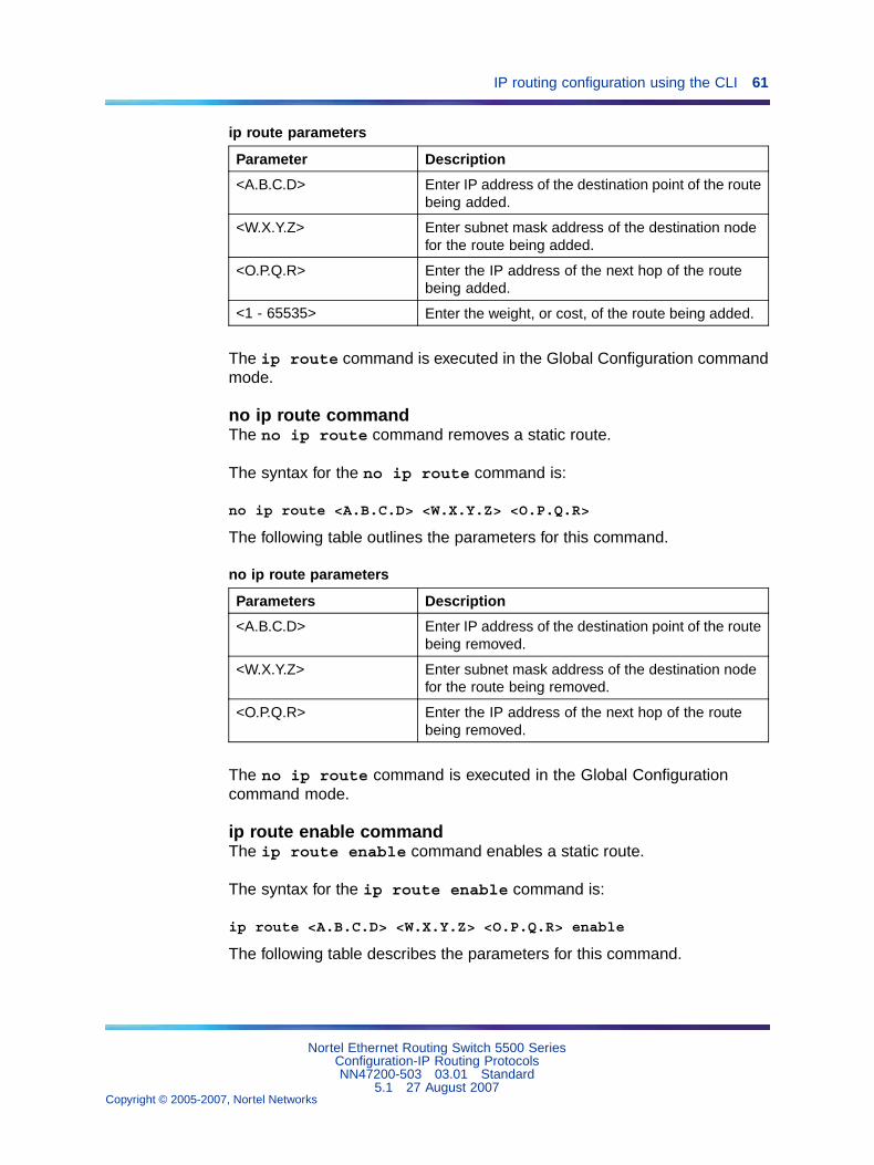
IP routing configuration using the CLI 61
ip route parameters
Parameter Description
<A.B.C.D> Enter IP address of the destination point of the routebeing added.
<W.X.Y.Z> Enter subnet mask address of the destination nodefor the route being added.
<O.P.Q.R> Enter the IP address of the next hop of the routebeing added.
<1 - 65535> Enter the weight, or cost, of the route being added.
The ip route command is executed in the Global Configuration commandmode.
no ip route commandThe no ip route command removes a static route.
The syntax for the no ip route command is:
no ip route <A.B.C.D> <W.X.Y.Z> <O.P.Q.R>
The following table outlines the parameters for this command.
no ip route parameters
Parameters Description
<A.B.C.D> Enter IP address of the destination point of the routebeing removed.
<W.X.Y.Z> Enter subnet mask address of the destination nodefor the route being removed.
<O.P.Q.R> Enter the IP address of the next hop of the routebeing removed.
The no ip route command is executed in the Global Configurationcommand mode.
ip route enable commandThe ip route enable command enables a static route.
The syntax for the ip route enable command is:
ip route <A.B.C.D> <W.X.Y.Z> <O.P.Q.R> enable
The following table describes the parameters for this command.
Nortel Ethernet Routing Switch 5500 SeriesConfiguration-IP Routing ProtocolsNN47200-503 03.01 Standard
5.1 27 August 2007Copyright © 2005-2007, Nortel Networks
.
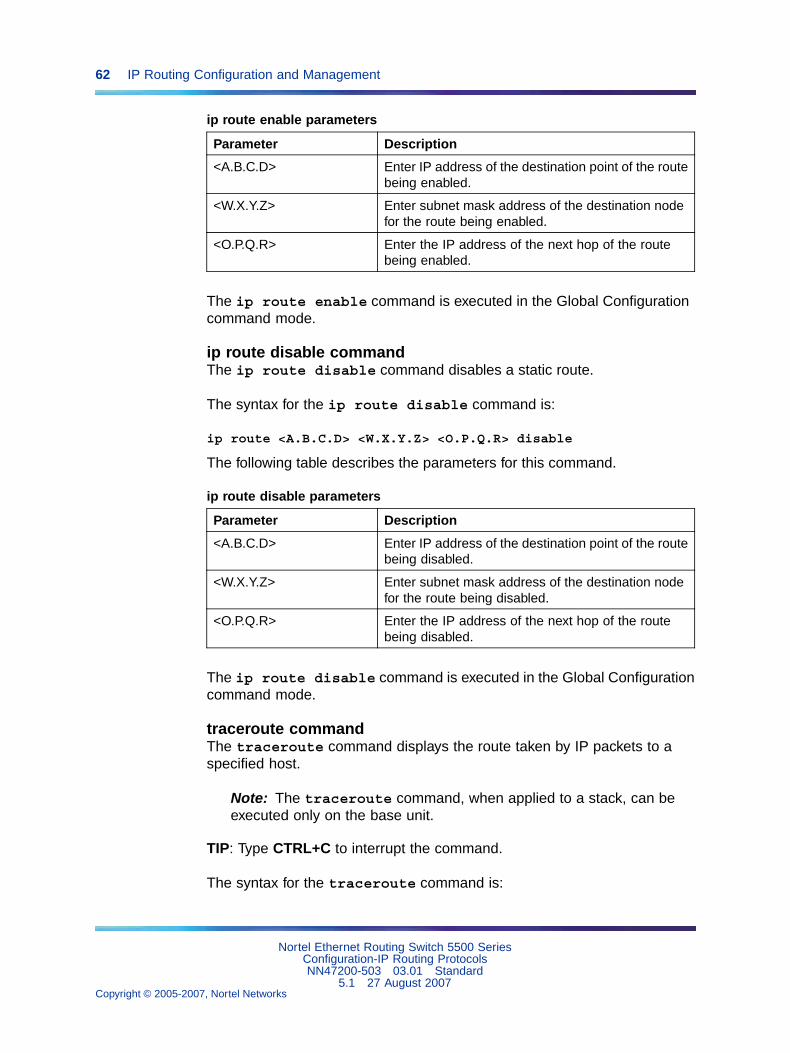
62 IP Routing Configuration and Management
ip route enable parameters
Parameter Description
<A.B.C.D> Enter IP address of the destination point of the routebeing enabled.
<W.X.Y.Z> Enter subnet mask address of the destination nodefor the route being enabled.
<O.P.Q.R> Enter the IP address of the next hop of the routebeing enabled.
The ip route enable command is executed in the Global Configurationcommand mode.
ip route disable commandThe ip route disable command disables a static route.
The syntax for the ip route disable command is:
ip route <A.B.C.D> <W.X.Y.Z> <O.P.Q.R> disable
The following table describes the parameters for this command.
ip route disable parameters
Parameter Description
<A.B.C.D> Enter IP address of the destination point of the routebeing disabled.
<W.X.Y.Z> Enter subnet mask address of the destination nodefor the route being disabled.
<O.P.Q.R> Enter the IP address of the next hop of the routebeing disabled.
The ip route disable command is executed in the Global Configurationcommand mode.
traceroute commandThe traceroute command displays the route taken by IP packets to aspecified host.
Note: The traceroute command, when applied to a stack, can beexecuted only on the base unit.
TIP: Type CTRL+C to interrupt the command.
The syntax for the traceroute command is:
Nortel Ethernet Routing Switch 5500 SeriesConfiguration-IP Routing ProtocolsNN47200-503 03.01 Standard
5.1 27 August 2007Copyright © 2005-2007, Nortel Networks
.
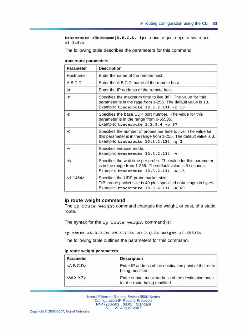
IP routing configuration using the CLI 63
traceroute <Hostname|A.B.C.D.|ip> <-m> <-p> <-q> <-v> <-w><1-1464>
The following table describes the parameters for this command.
traceroute parameters
Parameter Description
Hostname Enter the name of the remote host.
A.B.C.D. Enter the A.B.C.D. name of the remote host.
ip Enter the IP address of the remote host.
-m Specifies the maximum time to live (ttl). The value for thisparameter is in the rage from 1-255. The default value is 10.Example: traceroute 10.3.2.134 -m 10
-p Specifies the base UDP port number. The value for thisparameter is in the range from 0-65535.Example: traceroute 1.2.3.4 -p 87
-q Specifies the number of probes per time to live. The value forthis parameter is in the range from 1-255. The default value is 3.Example: traceroute 10.3.2.134 -q 3
-v Specifies verbose mode.Example: traceroute 10.3.2.134 -v
-w Specifies the wait time per probe. The value for this parameteris in the range from 1-255. The default value is 5 seconds.Example: traceroute 10.3.2.134 -w 15
<1-1464> Specifies the UDP probe packet size.TIP: probe packet size is 40 plus specified data length in bytes.Example: traceroute 10.3.2.134 -w 60
ip route weight commandThe ip route weight command changes the weight, or cost, of a staticroute.
The syntax for the ip route weight command is:
ip route <A.B.C.D> <W.X.Y.Z> <O.P.Q.R> weight <1-65535>
The following table outlines the parameters for this command.
ip route weight parameters
Parameter Description
<A.B.C.D> Enter IP address of the destination point of the routebeing modified.
<W.X.Y.Z> Enter subnet mask address of the destination nodefor the route being modified.
Nortel Ethernet Routing Switch 5500 SeriesConfiguration-IP Routing ProtocolsNN47200-503 03.01 Standard
5.1 27 August 2007Copyright © 2005-2007, Nortel Networks
.
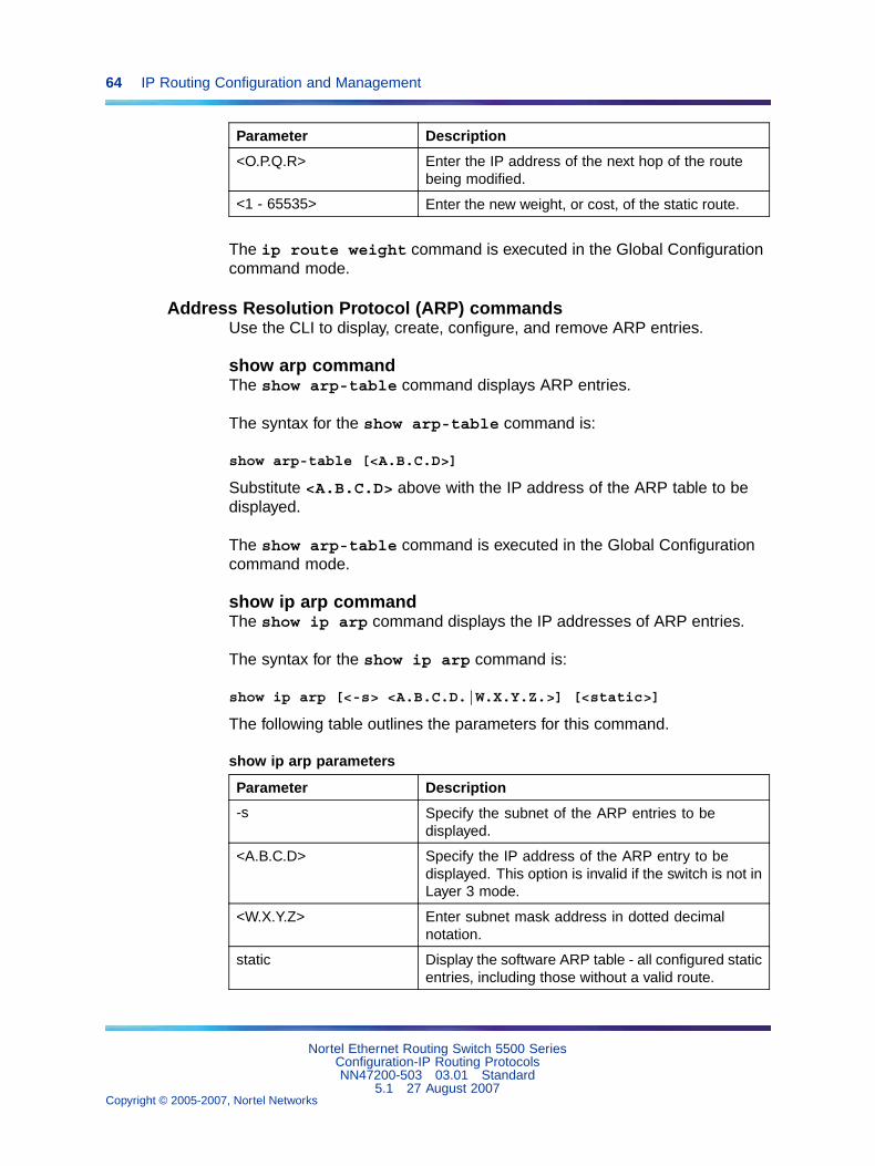
64 IP Routing Configuration and Management
Parameter Description
<O.P.Q.R> Enter the IP address of the next hop of the routebeing modified.
<1 - 65535> Enter the new weight, or cost, of the static route.
The ip route weight command is executed in the Global Configurationcommand mode.
Address Resolution Protocol (ARP) commandsUse the CLI to display, create, configure, and remove ARP entries.
show arp commandThe show arp-table command displays ARP entries.
The syntax for the show arp-table command is:
show arp-table [<A.B.C.D>]
Substitute <A.B.C.D> above with the IP address of the ARP table to bedisplayed.
The show arp-table command is executed in the Global Configurationcommand mode.
show ip arp commandThe show ip arp command displays the IP addresses of ARP entries.
The syntax for the show ip arp command is:
show ip arp [<-s> <A.B.C.D.|W.X.Y.Z.>] [<static>]
The following table outlines the parameters for this command.
show ip arp parameters
Parameter Description
-s Specify the subnet of the ARP entries to bedisplayed.
<A.B.C.D> Specify the IP address of the ARP entry to bedisplayed. This option is invalid if the switch is not inLayer 3 mode.
<W.X.Y.Z> Enter subnet mask address in dotted decimalnotation.
static Display the software ARP table - all configured staticentries, including those without a valid route.
Nortel Ethernet Routing Switch 5500 SeriesConfiguration-IP Routing ProtocolsNN47200-503 03.01 Standard
5.1 27 August 2007Copyright © 2005-2007, Nortel Networks
.
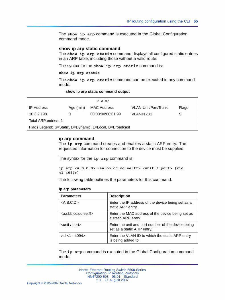
IP routing configuration using the CLI 65
The show ip arp command is executed in the Global Configurationcommand mode.
show ip arp static commandThe show ip arp static command displays all configured static entriesin an ARP table, including those without a valid route.
The syntax for the show ip arp static command is:
show ip arp static
The show ip arp static command can be executed in any commandmode.
show ip arp static command output
IP ARP
IP Address Age (min) MAC Address VLAN-Unit/Port/Trunk Flags
10.3.2.198 0 00:00:00:00:01:99 VLAN#1-1/1 S
Total ARP entries: 1
Flags Legend: S=Static, D=Dynamic, L=Local, B=Broadcast
ip arp commandThe ip arp command creates and enables a static ARP entry. Therequested information for connection to the device must be supplied.
The syntax for the ip arp command is:
ip arp <A.B.C.D> <aa:bb:cc:dd:ee:ff> <unit / port> [vid<1-4094>]
The following table outlines the parameters for this command.
ip arp parameters
Parameters Description
<A.B.C.D> Enter the IP address of the device being set as astatic ARP entry.
<aa:bb:cc:dd:ee:ff> Enter the MAC address of the device being set asa static ARP entry.
<unit / port> Enter the unit and port number of the device beingset as a static ARP entry.
vid <1 - 4094> Enter the VLAN ID to which the static ARP entryis being added to.
The ip arp command is executed in the Global Configuration commandmode.
Nortel Ethernet Routing Switch 5500 SeriesConfiguration-IP Routing ProtocolsNN47200-503 03.01 Standard
5.1 27 August 2007Copyright © 2005-2007, Nortel Networks
.
66 IP Routing Configuration and Management
no ip arp commandThe no ip arp command removes an ARP entry.
The syntax for the no ip arp command is:
no ip arp <A.B.C.D>
Substitute <A.B.C.D> above with the IP address of the static ARP entry toremove.
The no ip arp command is executed in the Global Configurationcommand mode.
ip arp timeout commandThe ip arp timeout command configures an aging time for the ARPentries.
The syntax for the ip arp timeout command is:
ip arp timeout <5-360>
Substitute <5-360> above with the amount of time in minutes before anARP entry ages out. The default value is 360 minutes.
The ip arp timeout command is executed in the Global Configurationcommand mode.
Proxy ARP commandsThis section outlines the commands used to configure and manage ProxyARP on the Nortel Ethernet Routing Switch 5500 Series.
ip arp-proxy commandThe ip arp-proxy command is used to enable proxy ARP functionalityon the switch
The syntax of the ip arp-proxy command is:
ip arp-proxy enable
The ip arp-proxy command is executed in the Layer 3 IP VLAN InterfaceConfiguration mode.
no ip arp-proxy commandThe no ip arp-proxy command is used to disable proxy ARPfunctionality on the switch.
The syntax of the no ip arp-proxy command is:
Nortel Ethernet Routing Switch 5500 SeriesConfiguration-IP Routing ProtocolsNN47200-503 03.01 Standard
5.1 27 August 2007Copyright © 2005-2007, Nortel Networks
.
IP routing configuration using the CLI 67
no ip arp-proxy [enable]
The no ip arp-proxy command is executed in the Layer 3 IP VLANInterface Configuration mode.
default ip arp-proxy commandThe default ip arp-proxy command is used to return the switch to thedefault proxy ARP settings.
The syntax of the default ip arp-proxy command is:
default ip arp-proxy [enable]
The default ip arp-proxy command is executed in the Layer 3 IPVLAN Interface Configuration mode.
show ip arp-proxy interface commandThe show ip arp-proxy interface command is used to display thestatus of proxy ARP on an interface.
The syntax of the show ip arp-proxy interface command is:
show ip arp-proxy interface [vlan <vlan_id>]
The show ip arp-proxy interface command is executed in the UserEXEC mode.
Routing Information Protocol (RIP) commandsThis section describes the CLI commands used to configure and managethe Routing Information Protocol (RIP) on the Nortel Ethernet RoutingSwitch 5500 Series. RIP is a distance vector protocol used to dynamicallydiscover network routes based on information passed between routers inthe network. RIP is useful in network environments where using static routeadministration would be difficult.
router rip enable commandThe router rip enable command is used to globally enable RIP onthe switch. RIP must be globally enabled on the switch before it becomesoperational.
The syntax of the router rip enable command is:
router rip enable
The router rip enable command is executed in the GlobalConfiguration command mode.
Nortel Ethernet Routing Switch 5500 SeriesConfiguration-IP Routing ProtocolsNN47200-503 03.01 Standard
5.1 27 August 2007Copyright © 2005-2007, Nortel Networks
.
68 IP Routing Configuration and Management
router rip commandThe router rip command is used to enter the Router Configurationmode for RIP. Router Configuration mode is used to configure variousaspects of RIP, OSPF (router ospf command), and VRRP (routervrrp command).
The syntax of the router rip command is:
router rip
The router rip command is executed in the Global Configurationcommand mode.
network commandThe network command is used to enable RIP on an IP interface.
The syntax of the network command is:
network <ip_address>
The <ip_address> parameter represents the IP address of the interfaceto be configured.
The network command is executed in the Router Configuration mode.
no network commandThe no network command is used to disable RIP on an IP interface.
The syntax of the no network command is:
no network <ip_address>
The <ip_address> parameter represents the IP address of the interfaceto be disabled.
The no network command is executed in the Router Configuration mode.
timers basic holddown commandThe timers basic holddown command is used to set the RIP holddowntimer.
The syntax of the timers basic holddown command is:
timers basic holddown <timer_value>
The <timer_value> parameter represents a value between 0 and 360seconds.
Nortel Ethernet Routing Switch 5500 SeriesConfiguration-IP Routing ProtocolsNN47200-503 03.01 Standard
5.1 27 August 2007Copyright © 2005-2007, Nortel Networks
.
IP routing configuration using the CLI 69
The timers basic holddown command is executed in the RouterConfiguration mode.
timers basic timeout commandThe timers basic timeout command is used to set the RIP timeouttimer.
The syntax of the timers basic timeout command is:
timers basic timeout <timer_value>
The <timer_value> parameter represents a value between 15 and259200 seconds.
The timers basic timeout command is executed in the RouterConfiguration mode.
timers basic update commandThe timers basic update command is used to set the RIP update timer.
The syntax of the timers basic update command is:
timers basic update <timer_value>
The <timer_value> parameter represents a value between 0 and 360seconds.
The default timers basic update command is executed in theRouter Configuration mode.
ip rip advertise-when-down commandThe ip rip advertise-when-down command is used to enable RIPadvertisements on the interface being configured even when that interfaceis not operational. The subnet on which the switch has a RIP enabledinterface is advertised even if that particular network is no longer connected(no link in the connected VLAN is in the Link-Up state). This setting willtake effect whenever the value is changed by the user or after the firstLink-Down transition.
The syntax of the ip rip advertise-when-down command is:
ip rip advertise-when-down {enable}
Advertise when down functionality is disabled by default.
The ip rip advertise-when-down command is executed in theInterface Configuration mode.
Nortel Ethernet Routing Switch 5500 SeriesConfiguration-IP Routing ProtocolsNN47200-503 03.01 Standard
5.1 27 August 2007Copyright © 2005-2007, Nortel Networks
.
70 IP Routing Configuration and Management
no ip rip advertise-when-down commandThe ip rip advertise-when-down command is used to disable RIPadvertisements on the interface being configured even when that interfaceis not operational.
The syntax of the no ip rip advertise-when-down command is:
no ip rip advertise-when-down {enable}
The no ip rip advertise-when-down command is executed in theInterface Configuration mode.
ip rip auto-aggregation commandThe ip rip auto-aggregation command is used to enable autoaggregation on the RIP interface. This allows for the automatic aggregationof routes to their natural net mask when they are advertised on an interfacein a different class network.
The syntax of the ip rip auto-aggregation command is:
ip rip auto-aggregation {enable}
Auto aggregation is disabled by default.
The ip rip auto-aggregation command is executed in the InterfaceConfiguration mode.
no ip rip auto-aggregation commandThe no ip rip auto-aggregation command is used to disableauto-aggregation on the RIP interface.
The syntax of the no ip rip auto-aggregation command is:
no ip rip auto-aggregation {enable}
The no ip rip auto-aggregation command is executed in theInterface Configuration mode.
ip rip cost commandThe ip rip cost command is used to set the administrative path costof the interface.
The syntax of the ip rip cost command is:
ip rip cost <path_cost>
The <path_cost> parameter represents a value between 1 and 15.
The default path cost is 1.
Nortel Ethernet Routing Switch 5500 SeriesConfiguration-IP Routing ProtocolsNN47200-503 03.01 Standard
5.1 27 August 2007Copyright © 2005-2007, Nortel Networks
.
IP routing configuration using the CLI 71
The ip rip cost command is executed in the Interface Configurationmode.
ip rip default-listen commandThe ip rip default-listen command is used to enable theacceptance of default route advertisements.
The syntax of the ip rip default-listen command is:
ip rip default-listen {enable}
The ip rip default-listen command is executed in the InterfaceConfiguration mode.
no ip rip default-listen commandThe no ip rip default-listen command is used to disable theacceptance of default route advertisements.
The syntax of the no ip rip default-listen command is:
no ip rip default-listen {enable}
The no ip rip default-listen command is executed in the InterfaceConfiguration mode.
ip rip default-supply commandThe ip rip default-supply command is used to enable theadvertisement of default routes on the interface.
The syntax of the ip rip default-supply command is:
ip rip default-supply {enable}
The ip rip default-supply command is executed in the InterfaceConfiguration mode.
no ip rip default-supply commandThe no ip rip default-supply command is used to disable theadvertisement of default routes on the interface.
The syntax of the no ip rip default-supply command is:
no ip rip default-supply {enable}
The no ip rip default-supply command is executed in the InterfaceConfiguration mode.
Nortel Ethernet Routing Switch 5500 SeriesConfiguration-IP Routing ProtocolsNN47200-503 03.01 Standard
5.1 27 August 2007Copyright © 2005-2007, Nortel Networks
.
72 IP Routing Configuration and Management
ip rip holddown commandThe ip rip holddown command is used to set the value of the holddowntimer on the RIP interface.
The syntax of the ip rip holddown command is:
ip rip holddown <timer_value>
The <timer_value> parameter is an integer value between 0 and 360seconds.
The ip rip holddown command is executed in the InterfaceConfiguration mode.
ip rip in-policy commandThe ip rip in-policy command is used to add an in policy to this RIPinterface.
The syntax of the ip rip in-policy command is:
ip rip in-policy <policy_name>
The <policy_name> parameter represents the name of a previouslyconfigured switch policy.
The ip rip in-policy command is executed in the InterfaceConfiguration mode.
no ip rip in-policy commandThe no ip rip in-policy command is used to remove a in policy forthe RIP interface.
The syntax of the no ip rip in-policy command is:
no ip rip in-policy <policy_name>
The <policy_name> parameter represents the name of a previouslyconfigured switch policy.
The no ip rip in-policy command is executed in the InterfaceConfiguration mode.
ip rip listen commandThe ip rip listen command is used to allow this interface to listen forRIP advertisements.
The syntax of the ip rip listen command is:
Nortel Ethernet Routing Switch 5500 SeriesConfiguration-IP Routing ProtocolsNN47200-503 03.01 Standard
5.1 27 August 2007Copyright © 2005-2007, Nortel Networks
.
IP routing configuration using the CLI 73
ip rip listen {enable}
The ip rip listen command is executed in the Interface Configurationmode.
no ip rip listen commandThe no ip rip listen command is used to prevent this interface fromlistening for RIP advertisements.
The syntax of the no ip rip listen command is:
ip rip listen {enable}
The no ip rip listen command is executed in the InterfaceConfiguration mode.
ip rip out-policy commandThe ip rip out-policy command is used to add an out policy to thisRIP interface.
The syntax of the ip rip out-policy command is:
ip rip out-policy <policy_name>
The <policy_name> parameter represents the name of a previouslyconfigured switch policy.
The ip rip out-policy command is executed in the InterfaceConfiguration mode.
no ip rip out-policy commandThe no ip rip out-policy command is used to remove an out policyfrom the RIP interface.
The syntax of the no ip rip out-policy command is:
no ip rip out-policy <policy_name>
The <policy_name> parameter represents the name of a previouslyconfigured switch policy.
The no ip rip out-policy command is executed in the InterfaceConfiguration mode.
ip rip poison commandThe ip rip poison command is used to enable poison reverse on thisRIP interface.
The syntax of the ip rip poison command is:
Nortel Ethernet Routing Switch 5500 SeriesConfiguration-IP Routing ProtocolsNN47200-503 03.01 Standard
5.1 27 August 2007Copyright © 2005-2007, Nortel Networks
.
74 IP Routing Configuration and Management
ip rip poison {enable}
The ip rip poison command is executed in the Interface Configurationmode.
no ip rip poison commandThe no ip rip poison command is used to disable poison reverse onthis RIP interface.
The syntax of the no ip rip poison command is:
no ip rip poison {enable}
The no ip rip poison command is executed in the InterfaceConfiguration mode.
ip rip proxy-announce commandThe ip rip proxy-announce command is used to enable proxyannouncements on this RIP interface. When proxy announcements areenabled, the source of a route and its next hop are treated as the samewhen processing received updates. So, instead of the advertising routerbeing used as the source, the next hop is.
The syntax of the ip rip proxy-announce command is:
ip rip proxy-announce {enable}
Proxy announcements are disabled by default.
The ip rip proxy-announce command is executed in the InterfaceConfiguration mode.
no ip rip proxy-announce commandThe no ip rip proxy-announce command is used to disable proxyannouncements on this RIP interface.
The syntax of the no ip rip proxy-announce command is:
no ip rip proxy-announce {enable}
The no ip rip proxy-announce command is executed in the InterfaceConfiguration mode.
ip rip receive commandThe ip rip receive command is used to set the RIP version receivedon this interface.
The syntax of the ip rip receive command is:
ip rip receive version <rip_version>
Nortel Ethernet Routing Switch 5500 SeriesConfiguration-IP Routing ProtocolsNN47200-503 03.01 Standard
5.1 27 August 2007Copyright © 2005-2007, Nortel Networks
.
IP routing configuration using the CLI 75
The <rip_version> parameter indicates the RIP version. The validvalues for this parameter are:
• rip1
• rip1orrip2
• rip2
The ip rip receive command is executed in the Interface Configurationmode.
ip rip send commandThe ip rip send command is used to set the RIP version sent on thisinterface.
The syntax of the ip rip send command is:
ip rip send version <rip_version>
The <rip_version> parameter indicates the RIP version. The validvalues for this parameter are:
• notsend
• rip1
• rip1comp
• rip2
The ip rip send command is executed in the Interface Configurationmode.
ip rip supply commandThe ip rip supply command is used to enable RIP route advertisementon this interface.
The syntax of the ip rip supply command is:
ip rip supply {enable}
The ip rip supply command is executed in the Interface Configurationmode.
no ip rip supply commandThe no ip rip supply command is used to disable RIP routeadvertisement on this interface.
The syntax of the no ip rip supply command is:
no ip rip supply {enable}
Nortel Ethernet Routing Switch 5500 SeriesConfiguration-IP Routing ProtocolsNN47200-503 03.01 Standard
5.1 27 August 2007Copyright © 2005-2007, Nortel Networks
.
76 IP Routing Configuration and Management
The no ip rip supply command is executed in the InterfaceConfiguration mode.
ip rip timeout commandThe ip rip timeout command is used to set the RIP timeout valueon this interface.
The syntax of the ip rip timeout command is:
ip rip timeout <timer_value>
The <timer_value> parameter is an integer value between 15 and259200 seconds.
The default timeout value is 180 seconds.
The command is executed in the Interface Configuration mode.
ip rip triggered commandThe ip rip triggered command is used to enable triggered updateson this RIP interface.
The syntax of the ip rip triggered command is:
ip rip triggered {enable}
The ip rip triggered command is executed in the InterfaceConfiguration mode.
no ip rip triggered commandThe no ip rip triggered command is used to disable triggeredupdates on this RIP interface.
The syntax of the no ip rip triggered command is:
no ip rip triggered {enable}
The no ip rip triggered command is executed in the InterfaceConfiguration mode.
show ip rip commandThe show ip rip command is used to display configuration and statisticalinformation about RIP.
The syntax of the show ip rip command is:
show ip rip [interface]
Nortel Ethernet Routing Switch 5500 SeriesConfiguration-IP Routing ProtocolsNN47200-503 03.01 Standard
5.1 27 August 2007Copyright © 2005-2007, Nortel Networks
.
IP routing configuration using the CLI 77
Use the interface key word to display RIP statistics by interface. Omission ofthis key word displays general RIP information
The show ip rip command is executed in the Global Configuration mode.
default router rip commandThe default router rip command is used to return the switch to thedefault global RIP state (disabled).
The syntax of the default router rip command is:
default router rip enable
The default router rip command is executed in the RouterConfiguration mode.
default default-metric commandThe default default-metric command is used to return the switchto the factory default RIP default import metric.
The syntax of the default default-metric command is:
default default-metric
The default default-metric command is executed in the RouterConfiguration mode.
default timers basic holddown commandThe default timers basic holddown command is used to return theswitch to the factory default RIP holddown timer.
The syntax of the default timers basic holddown command is:
default timers basic holddown
The default timers basic holddown command is executed in theRouter Configuration mode.
default timers basic timeout commandThe default timers basic timeout command is used to return theswitch to the factory default RIP timeout timer.
The syntax of the default timers basic timeout command is:
default timers basic timeout
The default timers basic timeout command is executed in theRouter Configuration mode.
Nortel Ethernet Routing Switch 5500 SeriesConfiguration-IP Routing ProtocolsNN47200-503 03.01 Standard
5.1 27 August 2007Copyright © 2005-2007, Nortel Networks
.
78 IP Routing Configuration and Management
default timers basic update commandThe default timers basic update command is used to return theswitch to the factory default RIP update timer.
The syntax of the default timers basic update command is:
default timers basic update
The default timers basic update command is executed in theRouter Configuration mode.
default-metric commandThe default-metric command is used to set the default RIP metricvalue.
The syntax of the default-metric command is:
default-metric <metric_value>
The <metric_value> parameter is an integer value between 0 and 15.
The default-metric command is executed in the Router Configurationmode.
default ip rip advertise-when-down commandThe default ip rip advertise-when-down command is used torestore the default RIP advertise when down setting for the interface(disabled).
The syntax of the default ip rip advertise-when-down commandis:
default ip rip advertise-when-down enable
The default ip rip advertise-when-down command is executed inthe Interface Configuration mode.
default ip rip auto-aggregation commandThe default ip rip auto-aggregation command is used to restorethe default RIP auto aggregation setting for the interface (disabled).
The syntax of the default ip rip auto-aggregation command is:
default ip rip auto-aggregation enable
The default ip rip auto-aggregation command is executed inthe Interface Configuration mode.
Nortel Ethernet Routing Switch 5500 SeriesConfiguration-IP Routing ProtocolsNN47200-503 03.01 Standard
5.1 27 August 2007Copyright © 2005-2007, Nortel Networks
.
IP routing configuration using the CLI 79
default ip rip cost commandThe default ip rip cost command is used to restore the default RIPcosting settings for the interface.
The syntax of the default ip rip cost command is:
default ip rip cost [[out-policy <policy_name>] | [poisonenable] | [proxy-announce enable] | [receive <rip_version>]| [send <rip_version>] | [supply enable] | [timeout] |[triggered enable]]
The default ip rip cost command is executed in the InterfaceConfiguration mode.
default ip rip default-listen commandThe default ip rip default-listen command is used to restorethe default RIP route listening setting for the interface (disabled).
The syntax of the default ip rip default-listen command is:
default ip rip default-listen enable
The default ip rip default-listen command is executed in theInterface Configuration mode.
default ip rip default-supply commandThe default ip rip default-supply command is used to restorethe default RIP route advertisement setting for the interface (disabled).
The syntax of the default ip rip default-supply command is:
default ip rip default-supply enable
The default ip rip default-supply command is executed in theInterface Configuration mode.
default ip rip enable commandThe default ip rip enable command is used to globally disable RIPon the interface.
The syntax of the default ip rip enable command is:
default ip rip enable
The default ip rip enable command is executed in the InterfaceConfiguration mode.
Nortel Ethernet Routing Switch 5500 SeriesConfiguration-IP Routing ProtocolsNN47200-503 03.01 Standard
5.1 27 August 2007Copyright © 2005-2007, Nortel Networks
.
80 IP Routing Configuration and Management
default ip rip holddown commandThe default ip rip holddown command is used to restore the defaultRIP holddown setting for the interface.
The syntax of the default ip rip holddown command is:
default ip rip holddown
The default ip rip holddown command is executed in the InterfaceConfiguration mode.
default ip rip in-policy commandThe default ip rip in-policy command is used to delete the inpolicy associated with this interface.
The syntax of the default ip rip in-policy command is:
default ip rip in-policy <policy_name>
The default ip rip in-policy command is executed in the InterfaceConfiguration mode.
default ip rip listen commandThe default ip rip listen command is used to set the ip rip listen tothe default value which is enabled.
The syntax of the default ip rip listen command is:
default ip rip listen enable
The default ip rip listen command is executed in the InterfaceConfiguration mode.
default ip rip out-policy commandThe default ip rip out-policy command is used to delete the outpolicy associated with this interface.
The syntax of the default ip rip out-policy command is:
default ip rip out-policy <policy_name>
The default ip rip out-policy command is executed in theInterface Configuration mode.
default ip rip poison commandThe default ip rip poison command is used to disable RIP poisonreverse on the interface.
The syntax of the default ip rip poison command is:
Nortel Ethernet Routing Switch 5500 SeriesConfiguration-IP Routing ProtocolsNN47200-503 03.01 Standard
5.1 27 August 2007Copyright © 2005-2007, Nortel Networks
.
IP routing configuration using the CLI 81
default ip rip poison enable
The default ip rip poison command is executed in the InterfaceConfiguration mode.
default ip rip proxy-announce commandThe default ip rip proxy-announce command is used to disableproxy announcement on the interface.
The syntax of the default ip rip proxy-announce command is:
default ip rip proxy-announce enable
The default ip rip proxy-announce command is executed in theInterface Configuration mode.
default ip rip receive commandThe default ip rip receive command is used to set the default RIPversion to listen to on this interface.
The syntax of the default ip rip receive command is:
default ip rip receive <rip_version>
The default ip rip receive command is executed in the InterfaceConfiguration mode.
default ip rip send commandThe default ip rip send command is used to set the default RIPversion to send on this interface.
The syntax of the default ip rip send command is:
default ip rip send <rip_version>
The default ip rip send command is executed in the InterfaceConfiguration mode.
default ip rip supply commandThe default ip rip supply command is used to set ip rip supply tothe default value which is enabled.
The syntax of the default ip rip supply command is:
default ip rip supply enable
The default ip rip supply command is executed in the InterfaceConfiguration mode.
Nortel Ethernet Routing Switch 5500 SeriesConfiguration-IP Routing ProtocolsNN47200-503 03.01 Standard
5.1 27 August 2007Copyright © 2005-2007, Nortel Networks
.
82 IP Routing Configuration and Management
default ip rip timeout commandThe default ip rip timeout command is used to restore the defaultRIP timeout setting for the interface.
The syntax of the default ip rip timeout command is:
default ip rip timeout
The default ip rip timeout command is executed in the InterfaceConfiguration mode.
default ip rip triggered commandThe default ip rip triggered command is used disabled triggeredupdates on this switch.
The syntax of the default ip rip triggered command is:
default ip rip triggered enable
The default ip rip triggered command is executed in the InterfaceConfiguration mode.
Open Shortest Path First (OSPF) commandsThis section describes the CLI commands used to configure and managethe Open Shortest Path First (OSPF) protocol on the Nortel EthernetRouting Switch 5500 Series. The Open Shortest Path First (OSPF) Protocolis an Interior Gateway Protocol (IGP) that distributes routing informationbetween routers belonging to a single autonomous system (AS). Intendedfor use in large networks, OSPF is a link-state protocol which supports IPsubnetting and the tagging of externally-derived routing information.
Note: OSPF commands used during the configuration and managementof VLANs in the Interface Configuration mode can be used to configureany VLAN regardless of the one used to log into the command mode.Insert the keyword vlan with the number of the VLAN to be configuredafter the command keywords ip ospf. The current VLAN will remain atthe one used to log into the Interface Configuration command modeafter the command execution.
ip ospf apply accept commandThe ip ospf apply accept command is used to apply OSPF acceptpolicies to the switch.
The syntax of the ip ospf apply accept command is:
ip ospf apply accept
Nortel Ethernet Routing Switch 5500 SeriesConfiguration-IP Routing ProtocolsNN47200-503 03.01 Standard
5.1 27 August 2007Copyright © 2005-2007, Nortel Networks
.
IP routing configuration using the CLI 83
The ip ospf apply accept command is executed in the GlobalConfiguration mode.
ip ospf apply redistribute direct commandThe ip ospf apply redistribute direct command is used toapply only direct OSPF redistribution configuration to the switch.
The syntax of the ip ospf apply redistribute direct command is:
ip ospf apply redistribute direct
The ip ospf apply redistribute direct command is executedin the Global Configuration mode.
ip ospf apply redistribute rip commandThe ip ospf apply redistribute rip command is used to applyonly RIP OSPF redistribution configuration on the switch.
The syntax of the ip ospf apply redistribute rip command is:
ip ospf apply redistribute rip
The ip ospf apply redistribute rip command is executed in theGlobal Configuration mode.
ip ospf apply redistribute static commandThe ip ospf apply redistribute static command is used toapply only static OSPF redistribution configuration on the switch.
The syntax of the ip ospf apply redistribute static command is:
ip ospf apply redistribute static
The ip ospf apply redistribute static command is executedin the Global Configuration mode.
ip ospf spf-run commandThe ip ospf spf-run command is used to immediately initiate an SPFrun upon holddown timer expiration to update the link state database.
The syntax of the ip ospf spf-run command is:
ip ospf spf-run
The ip ospf spf-run command is executed in the Global Configurationmode.
Nortel Ethernet Routing Switch 5500 SeriesConfiguration-IP Routing ProtocolsNN47200-503 03.01 Standard
5.1 27 August 2007Copyright © 2005-2007, Nortel Networks
.
84 IP Routing Configuration and Management
router ospf enable commandThe router ospf enable command is used to enable OSPF globallyon the switch.
The syntax of the router ospf enable command is:
router ospf enable
The router ospf enable command is executed in the GlobalConfiguration mode.
no router ospf enable commandThe no router ospf enable command is used to disable OSPFglobally on the switch.
The syntax of the no router ospf enable command is:
no router ospf enable
The no router ospf enable command is executed in the GlobalConfiguration mode.
router ospf commandThe router ospf command is used to place the switch into RouterConfiguration mode for the purposes of OSPF configuration.
The syntax of the router ospf command is:
router ospf
The router ospf command is executed in the Global Configuration mode.
default router ospf commandThe default router ospf command is used to return the switch to thedefault OSPF setting; which is disabled.
The syntax of the default router ospf command is:
default router ospf enable
The default router ospf command is executed in the GlobalConfiguration mode.
accept adv-rtr commandThe accept adv-rtr command is used to configure the router to acceptadvertisements from another router in the system.
The syntax of the accept adv-rtr command is:
Nortel Ethernet Routing Switch 5500 SeriesConfiguration-IP Routing ProtocolsNN47200-503 03.01 Standard
5.1 27 August 2007Copyright © 2005-2007, Nortel Networks
.
IP routing configuration using the CLI 85
accept adv-rtr <router_ip_address> [enable] [metric-type {any| type1 | type2}] [route-policy {policy_name}]
The following table outlines the parameters for this command.
accept adv-rtr parameters
Parameter Description
router_ip_address This parameter represents the IP address of the routeradvertisements will be accepted from. The value 0.0.0.0denotes that advertisements from all routers will beaccepted.
enable Enables the accept entry for the router specified in the<ip_address> parameter.
metric-type {any |type1 | type2}
Indicates the type of OSPF external routes that will beaccepted from this router.
route-policy{policy_name}
Specifies the name of the route policy to be used forfiltering external routes advertised by the specifiedadvertising router before accepting them into the routingtable.
The accept adv-rtr command is executed in the Router Configurationmode.
no accept adv-rtr commandThe no accept adv-rtr command is used to configure the router to notaccept advertisements from another router in the system.
The syntax of the no accept adv-rtr command is:
no accept adv-rtr <router_ip_address> enable
The <router_ip_address> parameter represents the address of the routerfrom which advertisements will no longer be accepted. The value 0.0.0.0denotes that advertisements from all routers will be blocked.
The no accept adv-rtr command is executed in the RouterConfiguration mode.
area commandThe area command is used to configure OSPF area parameters.
The syntax of the area command is:
area <ip_address> [default-cost {0-16777215}] [import{external | noexternal | nssa}] [import-summaries {enable}][range {subnet_mask} [{nssa-entlink | summary-link}]
Nortel Ethernet Routing Switch 5500 SeriesConfiguration-IP Routing ProtocolsNN47200-503 03.01 Standard
5.1 27 August 2007Copyright © 2005-2007, Nortel Networks
.
86 IP Routing Configuration and Management
[advertise-mode {no-summarize | summarize | suppress}][advertise-metric {0-65535}]]
The following table outlines the parameters for this command.
area parameters
Parameter Description
ip_address Specifies the Area ID expressed as IP address (A.B.C.D).
default-cost{0-16777215}
The default cost associated with an OSPF stub area.
import {external |noexternal | nssa}
The area’s support for importing Autonomous Systemexternal link state advertisements.
import-summaries{enable}
Controls the import of summary link state advertisementsinto stub areas. This setting has no effect on other areas.
range {subnet_mask}[{nssa-entlink |summary-link}][advertise-mode{ no-summarize| summarize| suppress}][advertise-metric{0-65535}]
Used to specify range parameters for the OSPF area.
The area command is executed in the Router Configuration mode.
Note: The configuration of a totally stubby area (no summaryadvertising) is a two step process. First, define an area with theimport flag set to noexternal. Second, disable import summariesin the same area with the command no area <ip_address>import-summaries enable.
no area commandThe no area command is used to disable configured OSPF areaparameters.
The syntax of the no area command is:
no area <ip_address> [import-summaries {enable} | range{subnet_mask} {nssa-entlink | summary-link}]
The following table outlines the parameters for this command.
Nortel Ethernet Routing Switch 5500 SeriesConfiguration-IP Routing ProtocolsNN47200-503 03.01 Standard
5.1 27 August 2007Copyright © 2005-2007, Nortel Networks
.
IP routing configuration using the CLI 87
no area parameters
Parameter Description
ip_address Specifies the Area ID expressed as IP address (A.B.C.D).
import-summaries{enable}
Controls the import of summary link state advertisementsinto stub areas. This setting has no effect on other areas.
range {subnet_mask}{nssa-entlink |summary-link}
Used to specify range parameters for the OSPF area.
The no area command is executed in the Router Configuration mode.
Note: The configuration of a totally stubby area (no summaryadvertising) is a two step process. First, define an area with theimport flag set to noexternal. Second, disable import summariesin the same area with the command no area <ip_address>import-summaries enable.
as-boundary-router commandThe as-boundary-router command is used to denote a router as anAutonomous System Boundary Router.
The syntax of the as-boundary-router command is:
as-boundary-router {enable}
The as-boundary-router command is executed in the RouterConfiguration mode.
no as-boundary-router commandThe no as-boundary-router command is used to withdraw a router asan Autonomous System Boundary Router.
The syntax of the no as-boundary-router command is:
no as-boundary-router {enable}
The no as-boundary-router command is executed in the RouterConfiguration mode.
default-cost ethernet commandThe default-cost ethernet command is used to define the defaultcost metric of an ethernet (10 Mbps) port.
The syntax of the default-cost ethernet command is:
default-cost ethernet <metric_value>
Nortel Ethernet Routing Switch 5500 SeriesConfiguration-IP Routing ProtocolsNN47200-503 03.01 Standard
5.1 27 August 2007Copyright © 2005-2007, Nortel Networks
.
88 IP Routing Configuration and Management
The <metric_value> parameter represents the cost value to assign tothe port. This value is an integer between 1 and 65535.
The default-cost ethernet command is executed in the RouterConfiguration mode.
default-cost fast-ethernet commandThe default-cost fast-ethernet command is used to define thedefault cost metric of a fast ethernet (100 Mbps) port.
The syntax of the default-cost fast-ethernet command is:
default-cost fast-ethernet <metric_value>
The <metric_value> parameter represents the cost value to assign tothe port. This value is an integer between 1 and 65535.
The default-cost fast-ethernet command is executed in the RouterConfiguration mode.
default-cost gig-ethernet commandThe default-cost gig-ethernet command is used to define thedefault cost metric of a gig ethernet (1000 Mbps) port.
The syntax of the default-cost gig-ethernet command is:
default-cost gig-ethernet <metric_value>
The <metric_value> parameter represents the cost value to assign tothe port. This value is an integer between 1 and 65535.
The default-cost gig-ethernet command is executed in the RouterConfiguration mode.
default-cost ten-gig-ethernet commandThe default-cost ten-gig-ethernet command is used to define thedefault cost metric of a ten gig ethernet (10000 Mbps) port.
The syntax of the default-cost ten-gig-ethernet command is:
default-cost ten-gig-ethernet <metric_value>
The <metric_value> parameter represents the cost value to assign tothe port. This value is an integer between 1 and 65535.
The default-cost ten-gig-ethernet command is executed in theRouter Configuration mode.
Nortel Ethernet Routing Switch 5500 SeriesConfiguration-IP Routing ProtocolsNN47200-503 03.01 Standard
5.1 27 August 2007Copyright © 2005-2007, Nortel Networks
.
IP routing configuration using the CLI 89
host-route commandUse the host-route command to add a host to a router. For moreinformation about host routes, see "OSPF host route" (page 29).
The syntax for the host-route command is:
host-route <A.B.C.D.> metric <0-65535>
where <A.B.C.D.> is the host IP address and metric is an integer between 0and 65535 representing the configured cost of the host
The host-route command is executed in the Router Configuration mode.
no host-route commandUse the no host-route command to delete a host from a router.
The syntax for the no host-route command is:
no host-route <A.B.C.D.>
where <A.B.C.D.> is the host IP address
The no host-route command is executed in the Router Configurationmode.
network commandThe network command is used to enable OSPF routing on an interfaceand assign an OSPF interface to an area.
The syntax of the network command is:
network <ip_address> [area <ip_address>]
The following table describes the parameters of this command.
network parameters
Field Description
<ip_address> The IP address of interface to be enabled for OSPF routing.
area <area_Id> The area assigned to the interface.
The network command is executed in the Router Configuration mode.
no network commandThe no network command is used to disable OSPF routing on aninterface.
The syntax of the no network command is:
Nortel Ethernet Routing Switch 5500 SeriesConfiguration-IP Routing ProtocolsNN47200-503 03.01 Standard
5.1 27 August 2007Copyright © 2005-2007, Nortel Networks
.
90 IP Routing Configuration and Management
no network <ip_address>
The <ip_address> parameter represents the IP address of the interface tobe disabled.
The no network command is executed in the Router Configuration mode.
redistribute commandThe redistribute command is used to configure OSPF routeredistribution. Direct, RIP, and static route redistribution is currentlysupported.
The syntax of the redistribute command is:
redistribute <route_type> [enable] [metric <metric_value>][metric-type <metric_type>] [route-policy <policy_name>][subnets <subnet_setting>]
The parameters for this command are listed below.
redistribute parameters
Parameters Description
<route_type> The type of route to be configured. Valid options aredirect, rip, and static.
<metric_value> The metric value to associate with the route redistribution.This is an integer value between 0 and 65535.
<metric_type> The metric type to associate with the route redistribution.Valid options are type1 and type2.
<policy_name> The route policy to associate with route redistribution.This is the name of an existing route policy.
<subnet_setting> The subnet advertisement setting of this routeredistribution. This determines whether individual subnetsare advertised. Valid options are allow and suppress.
The redistribute command is executed in the Router Configurationmode.
no redistribute commandThe no redistribute command is used to disable an OSPF route policyor OSPF route redistribution completely.
The syntax of the no redistribute command is:
redistribute <route_type> [enable] [route-policy<policy_name>]
The parameters for this command are listed below.
Nortel Ethernet Routing Switch 5500 SeriesConfiguration-IP Routing ProtocolsNN47200-503 03.01 Standard
5.1 27 August 2007Copyright © 2005-2007, Nortel Networks
.
IP routing configuration using the CLI 91
no redistribute parameters
Parameters Description
<route_type> The type of route to be configured. Valid options aredirect, rip, and static.
<policy_name> The route policy to remove from the route redistribution.This is the name of an existing route policy.
The no redistribute command is executed in the Router Configurationmode.
rfc1583-compatibility commandThe rfc1583-compatibility command is used to enable compatibilityfor RFC 1583 in the switch OSPF implementation.
The syntax of the rfc1583-compatibility command is:
rfc1583-compatibility enable
The rfc1583-compatibility command is executed in the RouterConfiguration mode.
no rfc1583-compatibility commandThe no rfc1583-compatibility command is used to disablecompatibility for RFC 1583 in the switch OSPF implementation.
The syntax of the no rfc1583-compatibility command is:
no rfc1583-compatibility enable
The no rfc1583-compatibility command is executed in the RouterConfiguration mode.
router-id commandThe router-id command is used to set the identifier to the user-configuredrouter ID, which is expressed in the form of an IP address.
The syntax of the router-id command is:
router-id <router_id>
The <router_id> parameter is used as the unique identifier for the router.
The router-id command is executed in the Router Configuration mode.
no router-id commandThe no router-id command is used to reset the router ID to 0.0.0.0.
Nortel Ethernet Routing Switch 5500 SeriesConfiguration-IP Routing ProtocolsNN47200-503 03.01 Standard
5.1 27 August 2007Copyright © 2005-2007, Nortel Networks
.
92 IP Routing Configuration and Management
The syntax of the no router-id command is:
no router-id
The no router-id command is executed in the Router Configurationmode.
timers basic holddown commandThe timers basic holddown command is used to configure the OSPFholddown timer.
The syntax of the timers basic holddown command is:
timers basic holddown <timer_value>
The <timer_value> parameter represents a second value between 3and 60 seconds.
The command is executed in the Router Configuration mode.
trap commandThe trap command is used to enable OSPF system traps.
The syntax of the trap command is:
trap enable
The trap command is executed in the Router Configuration mode.
no trap commandThe no trap command is used to disable OSPF system traps.
The syntax of the no trap command is:
no trap enable
The no trap command is executed in the Router Configuration mode.
area virtual-link commandUse the area virtual-link command to create a virtual interface.
The syntax for the area virtual-link command is:
area virtual-link <A.B.C.D.> <W.X.Y.Z> {[authentication-key<WORD>] [authentication-type {none|simple|message-digest}][primary-md5-key <1-255>] [dead-interval <0-2147483647>][hello-interval <1-65535>] [retransmit-interval <0-3600>][transit-delay <0-3600>]
Nortel Ethernet Routing Switch 5500 SeriesConfiguration-IP Routing ProtocolsNN47200-503 03.01 Standard
5.1 27 August 2007Copyright © 2005-2007, Nortel Networks
.
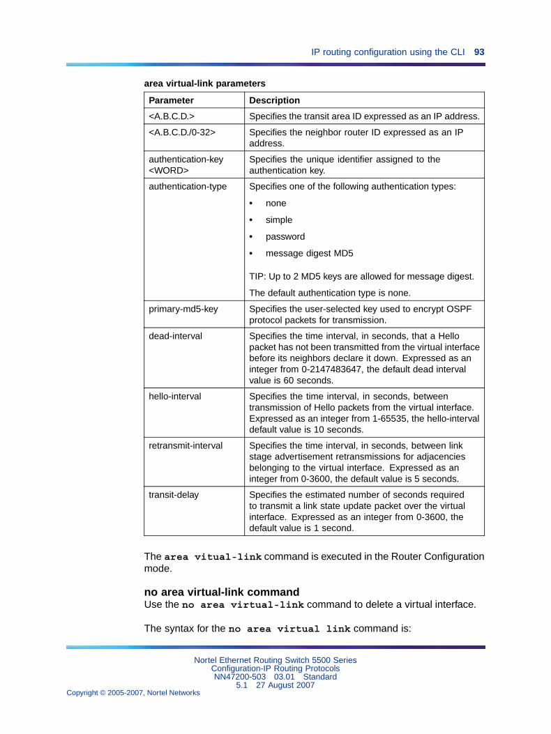
IP routing configuration using the CLI 93
area virtual-link parameters
Parameter Description
<A.B.C.D.> Specifies the transit area ID expressed as an IP address.
<A.B.C.D./0-32> Specifies the neighbor router ID expressed as an IPaddress.
authentication-key<WORD>
Specifies the unique identifier assigned to theauthentication key.
authentication-type Specifies one of the following authentication types:
• none
• simple
• password
• message digest MD5
TIP: Up to 2 MD5 keys are allowed for message digest.
The default authentication type is none.
primary-md5-key Specifies the user-selected key used to encrypt OSPFprotocol packets for transmission.
dead-interval Specifies the time interval, in seconds, that a Hellopacket has not been transmitted from the virtual interfacebefore its neighbors declare it down. Expressed as aninteger from 0-2147483647, the default dead intervalvalue is 60 seconds.
hello-interval Specifies the time interval, in seconds, betweentransmission of Hello packets from the virtual interface.Expressed as an integer from 1-65535, the hello-intervaldefault value is 10 seconds.
retransmit-interval Specifies the time interval, in seconds, between linkstage advertisement retransmissions for adjacenciesbelonging to the virtual interface. Expressed as aninteger from 0-3600, the default value is 5 seconds.
transit-delay Specifies the estimated number of seconds requiredto transmit a link state update packet over the virtualinterface. Expressed as an integer from 0-3600, thedefault value is 1 second.
The area vitual-link command is executed in the Router Configurationmode.
no area virtual-link commandUse the no area virtual-link command to delete a virtual interface.
The syntax for the no area virtual link command is:
Nortel Ethernet Routing Switch 5500 SeriesConfiguration-IP Routing ProtocolsNN47200-503 03.01 Standard
5.1 27 August 2007Copyright © 2005-2007, Nortel Networks
.
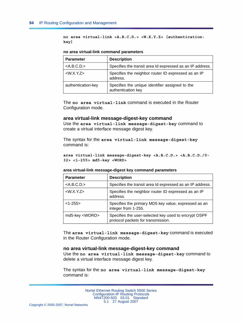
94 IP Routing Configuration and Management
no area virtual-link <A.B.C.D.> <W.X.Y.Z> [authentication-key]
no area virtual-link command parameters
Parameter Description
<A.B.C.D.> Specifies the transit area Id expressed as an IP address.
<W.X.Y.Z> Specifies the neighbor router ID expressed as an IPaddress.
authentication-key Specifies the unique identifier assigned to theauthentication key
The no area virtual-link command is executed in the RouterConfiguration mode.
area virtual-link message-digest-key commandUse the area virtual-link message-digest-key command tocreate a virtual interface message digest key.
The syntax for the area virtual-link message-digest-keycommand is:
area virtual-link message-digest-key <A.B.C.D.> <A.B.C.D./0-32> <1-255> md5-key <WORD>
area virtual-link message-digest key command parameters
Parameter Description
<A.B.C.D.> Specifies the transit area Id expressed as an IP address.
<W.X.Y.Z> Specifies the neighbor router ID expressed as an IPaddress.
<1-255> Specifies the primary MD5 key value, expressed as aninteger from 1-255.
md5-key <WORD> Specifies the user-selected key used to encrypt OSPFprotocol packets for transmission.
The area virtual-link message-digest-key command is executedin the Router Configuration mode.
no area virtual-link message-digest-key commandUse the no area virtual-link message-digest-key command todelete a virtual interface message digest key.
The syntax for the no area virtual-link message-digest-keycommand is:
Nortel Ethernet Routing Switch 5500 SeriesConfiguration-IP Routing ProtocolsNN47200-503 03.01 Standard
5.1 27 August 2007Copyright © 2005-2007, Nortel Networks
.
IP routing configuration using the CLI 95
no area virtual-link message-digest-key <A.B.C.D.> <W.X.Y.Z><1-255>
no area virtual-link message-digest-key command parameters
Parameter Description
<A.B.C.D.> Specifies the transit area ID expressed as an IP address.
<W.X.Y.Z> Specifies the neighbor router ID expressed as an IPaddress.
<1-255> Specifies the primary MD5 key value, expressed as aninteger from 1-255.
The no area virtual-link message-digest-key command isexecuted in the Router Configuration mode.
auto-vlink commandUse the auto-vlink command to enable global automatic Virtual Link creation.For more information about Virtual Link, see "OSPF virtual link" (page 31)
The syntax for the auto-vlink command is:
auto-vlink
The auto-vlink command is executed in the Router Configuration mode.
no auto-vlink commandUse the no auto-vlink command to disable global automatic VirtualLink creation.
The syntax for the no auto-vlink command is:
no auto-vlink
The no auto-vlink command is executed in the Router Configurationmode.
ip ospf advertise-when-down commandThe ip ospf advertise-when-down command is used to enableadvertisement of the OSPF interface even when the interface is operationallyunavailable.
The syntax of the ip ospf advertise-when-down command is:
ip ospf advertise-when-down enable
The ip ospf advertise-when-down command is executed in theInterface Configuration mode.
Nortel Ethernet Routing Switch 5500 SeriesConfiguration-IP Routing ProtocolsNN47200-503 03.01 Standard
5.1 27 August 2007Copyright © 2005-2007, Nortel Networks
.
96 IP Routing Configuration and Management
ip ospf area commandThe ip ospf area command is used to assign an interface to an OSPFarea.
The syntax of the ip ospf area command is:
ip ospf area <ip_address>
The <ip_address> parameter represents the unique ID of the area towhich the interface connects. An area ID of 0.0.0.0 indicates the OSPF areabackbone and is created automatically by the switch.
The ip ospf area command is executed in the Interface Configurationmode.
ip ospf authentication-key commandThe ip ospf authentication-key command is used to configure aninterface authentication password.
The syntax of the ip ospf authentication-key command is:
ip opsf authentication-key <password>
The <password> parameter is the password to be configured. Thispassword can be up to 8 characters in length.
The ip opsf authentication-key command is executed in theInterface Configuration mode.
ip ospf authentication-type commandThe ip ospf authentication-type command is used to configure theinterface authentication type.
The syntax of the ip ospf authentication-type command is:
ip ospf authentication-type {message-digest | simple | none}
The ip ospf authentication-type command is executed in theInterface Configuration mode.
ip ospf cost commandThe ip ospf cost command is used to assign a cost to an interface.
The syntax of the ip ospf cost command is:
ip ospf cost <interface_cost>
The <interface_cost> parameter is the cost assigned to the interface.This is an integer value between 1 and 65535.
Nortel Ethernet Routing Switch 5500 SeriesConfiguration-IP Routing ProtocolsNN47200-503 03.01 Standard
5.1 27 August 2007Copyright © 2005-2007, Nortel Networks
.
IP routing configuration using the CLI 97
The ip ospf cost command is executed in the Interface Configurationmode.
ip ospf dead-interval commandThe ip ospf dead-interval command is used to configure a deadinterval for the interface. This is the interval of time that a Hello packet hasnot been transmitted from this interface before its neighbors declare it down.
The syntax of the ip ospf dead-interval command is:
ip ospf dead-interval <interval>
The <interval> parameter represents the amount of time in seconds toset this interval at. This is an integer value between 0 and 2147483647.
The ip ospf dead-interval command is executed in the InterfaceConfiguration mode.
ip ospf hello-interval commandThe ip ospf hello-interval command is used to configure theamount of time between transmission of hello packets from this interface.
The syntax of the ip ospf hello-interval command is:
ip ospf hello-interval <interval>
The <interval> parameter is the amount of time in seconds betweenhello packets. This is an integer value between 1 and 65535.
The ip ospf hello-interval command is executed in the InterfaceConfiguration mode.
ip ospf mtu-ignore commandThe ip ospf mtu-ignore command is used to instruct the interface toignore the packet MTU size specified in Database Descriptors.
The syntax of the ip ospf mtu-ignore command is:
ip ospf mtu-ignore enable
The ip ospf mtu-ignore command is executed in the InterfaceConfiguration mode.
ip ospf network commandThe ip ospf network command is used to define the type of OSPFinterface this interface is.
The syntax of the ip ospf network command is:
Nortel Ethernet Routing Switch 5500 SeriesConfiguration-IP Routing ProtocolsNN47200-503 03.01 Standard
5.1 27 August 2007Copyright © 2005-2007, Nortel Networks
.
98 IP Routing Configuration and Management
ip ospf network {broadcast | passive}
The ip ospf network command is executed in the InterfaceConfiguration mode.
ip ospf primary-md5-key commandThe ip ospf primary-md5-key command is used to configure theprimary MD5 key to use for authentication in instances where interfaceauthentication uses an MD5 key.
The syntax of the ip ospf primary-md5-key command is:
ip ospf primary-md5-key <key_value>
The <key_value> parameter is an integer value between 1 and 255.
The ip ospf primary-md5-key command is executed in the InterfaceConfiguration mode.
ip ospf priority commandThe ip ospf priority command is used to assign a priority to theinterface for the purposes of Designated Router election.
The syntax of the ip ospf priority command is:
ip ospf priority <priority_value>
The <priority_value> parameter is the priority value assigned to theinterface. This is an integer value between 0 and 255.
The ip ospf priority command is executed in the InterfaceConfiguration mode.
ip ospf retransmit-interval commandThe ip ospf retransmit-interval command is used to define thenumber of seconds between link state advertisement retransmissions foradjacencies belonging to this interface.
The syntax of the ip ospf retransmit-interval command is:
ip ospf retransmit-interval <interval>
The <interval> parameter is the number of seconds betweenretransmissions. This is an integer value between 0 and 3600.
The ip ospf retransmit-interval command is executed in theInterface Configuration mode.
Nortel Ethernet Routing Switch 5500 SeriesConfiguration-IP Routing ProtocolsNN47200-503 03.01 Standard
5.1 27 August 2007Copyright © 2005-2007, Nortel Networks
.
IP routing configuration using the CLI 99
ip ospf transmit-delay commandThe ip ospf transmit-delay command is used to define the transmitdelay for this OSPF interface.
The syntax of the ip ospf transmit-delay command is:
ip ospf transmit-delay <interval>
The <interval> parameter is the transmit delay in seconds. This is aninteger value between 0 and 3600.
The ip ospf transmit-delay command is executed in the InterfaceConfiguration mode.
ip ospf message-digest-key commandThe ip ospf message-digest-key command is used to define theMD5 keys referenced in the ip ospf primary-md5-key command.
The syntax of the ip ospf message-digest-key command is:
ip ospf message-digest-key <key_number> md5 <key_value>
The <key_number> parameter represents the MD5 key to be configured.This is an integer value between 1 and 255. The <key_value> parameterrepresents the value of the key being configured. This is a string value of upto 16 characters in length.
The ip ospf message-digest-key command is executed in theInterface Configuration mode.
OSPF show commandsOSPF functionality provides a wide range of commands used to displaystatistics and configured parameters for the router. These commands areavailable for use in any command mode. OSPF Show commands areoutlined in the table below.
OSPF show commands
Command Description
show ip ospf Displays general information on OSPFconfiguration.
show ip ospf accept Displays information on OSPF advertisingrouters.
show ip ospf area<ip_address>
Displays configuration information about theOSPF area specified in the <ip_address>parameter. Omitting this parameter displaysinformation for all OSPF areas.
Nortel Ethernet Routing Switch 5500 SeriesConfiguration-IP Routing ProtocolsNN47200-503 03.01 Standard
5.1 27 August 2007Copyright © 2005-2007, Nortel Networks
.
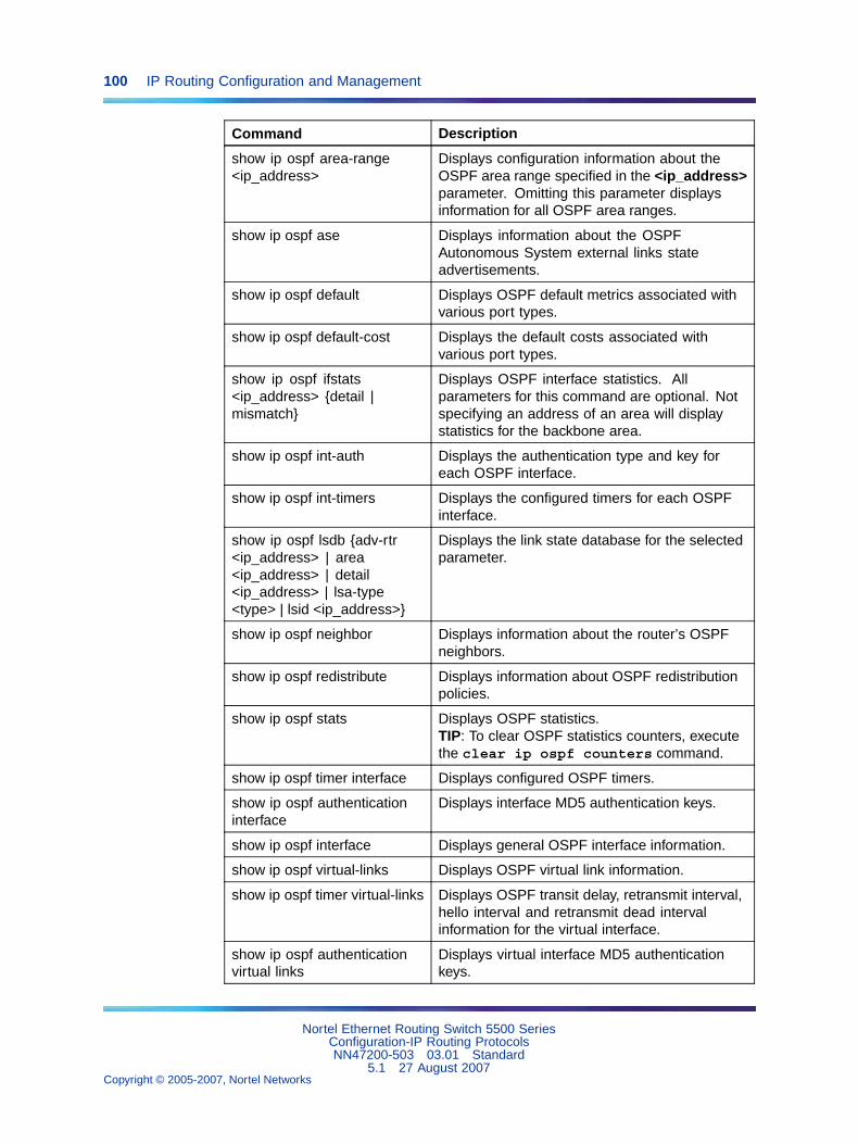
100 IP Routing Configuration and Management
Command Description
show ip ospf area-range<ip_address>
Displays configuration information about theOSPF area range specified in the <ip_address>parameter. Omitting this parameter displaysinformation for all OSPF area ranges.
show ip ospf ase Displays information about the OSPFAutonomous System external links stateadvertisements.
show ip ospf default Displays OSPF default metrics associated withvarious port types.
show ip ospf default-cost Displays the default costs associated withvarious port types.
show ip ospf ifstats<ip_address> {detail |mismatch}
Displays OSPF interface statistics. Allparameters for this command are optional. Notspecifying an address of an area will displaystatistics for the backbone area.
show ip ospf int-auth Displays the authentication type and key foreach OSPF interface.
show ip ospf int-timers Displays the configured timers for each OSPFinterface.
show ip ospf lsdb {adv-rtr<ip_address> | area<ip_address> | detail<ip_address> | lsa-type<type> | lsid <ip_address>}
Displays the link state database for the selectedparameter.
show ip ospf neighbor Displays information about the router’s OSPFneighbors.
show ip ospf redistribute Displays information about OSPF redistributionpolicies.
show ip ospf stats Displays OSPF statistics.TIP: To clear OSPF statistics counters, executethe clear ip ospf counters command.
show ip ospf timer interface Displays configured OSPF timers.
show ip ospf authenticationinterface
Displays interface MD5 authentication keys.
show ip ospf interface Displays general OSPF interface information.
show ip ospf virtual-links Displays OSPF virtual link information.
show ip ospf timer virtual-links Displays OSPF transit delay, retransmit interval,hello interval and retransmit dead intervalinformation for the virtual interface.
show ip ospf authenticationvirtual links
Displays virtual interface MD5 authenticationkeys.
Nortel Ethernet Routing Switch 5500 SeriesConfiguration-IP Routing ProtocolsNN47200-503 03.01 Standard
5.1 27 August 2007Copyright © 2005-2007, Nortel Networks
.
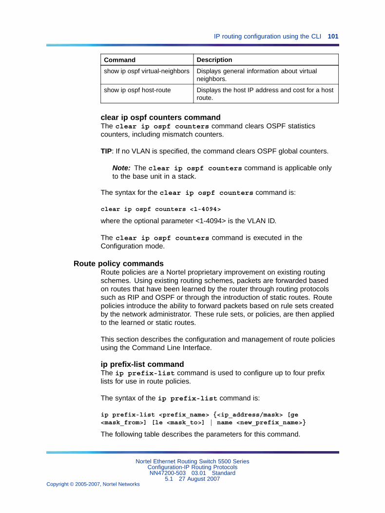
IP routing configuration using the CLI 101
Command Description
show ip ospf virtual-neighbors Displays general information about virtualneighbors.
show ip ospf host-route Displays the host IP address and cost for a hostroute.
clear ip ospf counters commandThe clear ip ospf counters command clears OSPF statisticscounters, including mismatch counters.
TIP: If no VLAN is specified, the command clears OSPF global counters.
Note: The clear ip ospf counters command is applicable onlyto the base unit in a stack.
The syntax for the clear ip ospf counters command is:
clear ip ospf counters <1-4094>
where the optional parameter <1-4094> is the VLAN ID.
The clear ip ospf counters command is executed in theConfiguration mode.
Route policy commandsRoute policies are a Nortel proprietary improvement on existing routingschemes. Using existing routing schemes, packets are forwarded basedon routes that have been learned by the router through routing protocolssuch as RIP and OSPF or through the introduction of static routes. Routepolicies introduce the ability to forward packets based on rule sets createdby the network administrator. These rule sets, or policies, are then appliedto the learned or static routes.
This section describes the configuration and management of route policiesusing the Command Line Interface.
ip prefix-list commandThe ip prefix-list command is used to configure up to four prefixlists for use in route policies.
The syntax of the ip prefix-list command is:
ip prefix-list <prefix_name> {<ip_address/mask> [ge<mask_from>] [le <mask_to>] | name <new_prefix_name>}
The following table describes the parameters for this command.
Nortel Ethernet Routing Switch 5500 SeriesConfiguration-IP Routing ProtocolsNN47200-503 03.01 Standard
5.1 27 August 2007Copyright © 2005-2007, Nortel Networks
.
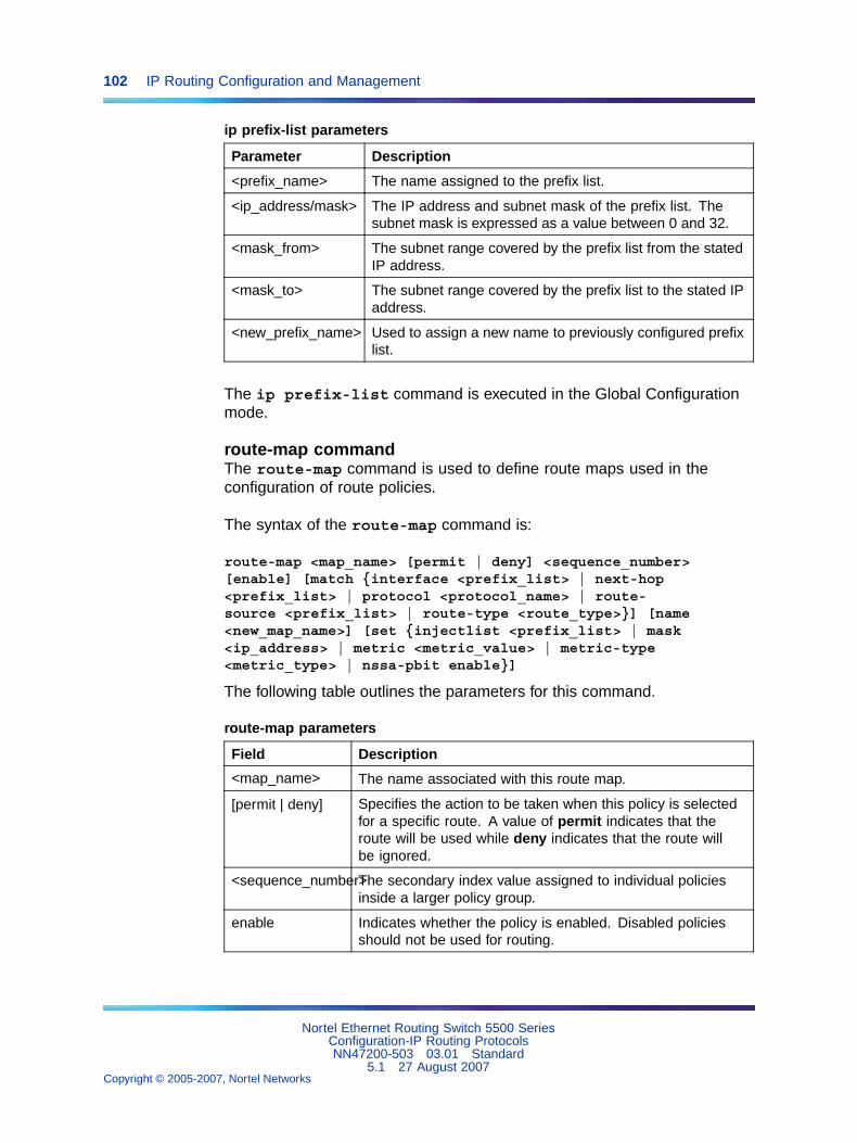
102 IP Routing Configuration and Management
ip prefix-list parameters
Parameter Description
<prefix_name> The name assigned to the prefix list.
<ip_address/mask> The IP address and subnet mask of the prefix list. Thesubnet mask is expressed as a value between 0 and 32.
<mask_from> The subnet range covered by the prefix list from the statedIP address.
<mask_to> The subnet range covered by the prefix list to the stated IPaddress.
<new_prefix_name> Used to assign a new name to previously configured prefixlist.
The ip prefix-list command is executed in the Global Configurationmode.
route-map commandThe route-map command is used to define route maps used in theconfiguration of route policies.
The syntax of the route-map command is:
route-map <map_name> [permit | deny] <sequence_number>[enable] [match {interface <prefix_list> | next-hop<prefix_list> | protocol <protocol_name> | route-source <prefix_list> | route-type <route_type>}] [name<new_map_name>] [set {injectlist <prefix_list> | mask<ip_address> | metric <metric_value> | metric-type<metric_type> | nssa-pbit enable}]
The following table outlines the parameters for this command.
route-map parameters
Field Description
<map_name> The name associated with this route map.
[permit | deny] Specifies the action to be taken when this policy is selectedfor a specific route. A value of permit indicates that theroute will be used while deny indicates that the route willbe ignored.
<sequence_number>The secondary index value assigned to individual policiesinside a larger policy group.
enable Indicates whether the policy is enabled. Disabled policiesshould not be used for routing.
Nortel Ethernet Routing Switch 5500 SeriesConfiguration-IP Routing ProtocolsNN47200-503 03.01 Standard
5.1 27 August 2007Copyright © 2005-2007, Nortel Networks
.
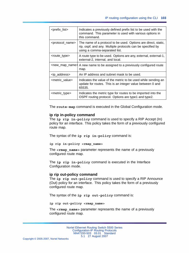
IP routing configuration using the CLI 103
<prefix_list> Indicates a previously defined prefix list to be used with thecommand. This parameter is used with various options inthis command.
<protocol_name> The name of a protocol to be used. Options are direct, static,rip, ospf, and any. Multiple protocols can be specified byusing a comma-separated list.
<route_type> A route type to be used. Options are any, external, external-1,external-2, internal, and local.
<new_map_name> A new name to be assigned to a previously configured routemap.
<ip_address> An IP address and subnet mask to be used.
<metric_value> Indicates the value of the metric to be used while sending anupdate for routes. This is an integer value between 0 and65535.
<metric_type> Indicates the metric type for routes to be imported into theOSPF routing protocol. Options are type1 and type2.
The route-map command is executed in the Global Configuration mode.
ip rip in-policy commandThe ip rip in-policy command is used to specify a RIP Accept (In)policy for an interface. This policy takes the form of a previously configuredroute map.
The syntax of the ip rip in-policy command is:
ip rip in-policy <rmap_name>
The <rmap_name> parameter represents the name of a previouslyconfigured route map.
The ip rip in-policy command is executed in the InterfaceConfiguration mode.
ip rip out-policy commandThe ip rip out-policy command is used to specify a RIP Announce(Out) policy for an interface. This policy takes the form of a previouslyconfigured route map.
The syntax of the ip rip out-policy command is:
ip rip out-policy <rmap_name>
The <rmap_name> parameter represents the name of a previouslyconfigured route map.
Nortel Ethernet Routing Switch 5500 SeriesConfiguration-IP Routing ProtocolsNN47200-503 03.01 Standard
5.1 27 August 2007Copyright © 2005-2007, Nortel Networks
.
104 IP Routing Configuration and Management
The ip rip out-policy command is executed in the InterfaceConfiguration mode.
Virtual Router Redundancy Protocol (VRRP) commandsThe Virtual Router Redundancy Protocol (VRRP) is designed to eliminatethe single point of failure that can occur when the single static defaultgateway router for an end station is lost.
This section describes the CLI commands used to configure VRRP.
router vrrp enable commandThe router vrrp enable command is used to globally enable VRRPon a switch.
The syntax of the router vrrp enable command is:
router vrrp enable
The router vrrp enable command is executed in the GlobalConfiguration mode.
no router vrrp enable commandThe no router vrrp enable command is used to globally disableVRRP on a switch.
The syntax of the no router vrrp enable command is:
no router vrrp enable
The no router vrrp enable command is executed in the GlobalConfiguration mode.
router vrrp commandThe router vrrp command is used to place the switch into RouterConfiguration mode for the purposes of VRRP configuration.
The syntax of the router vrrp command is:
router vrrp
The router vrrp command is executed in the Global Configuration mode.
ping-virtual-address enable commandThe ping-virtual-address enable command is used to enable ICMPecho replies from VRRP associated addresses.
The syntax of the ping-virtual-address enable command is:
Nortel Ethernet Routing Switch 5500 SeriesConfiguration-IP Routing ProtocolsNN47200-503 03.01 Standard
5.1 27 August 2007Copyright © 2005-2007, Nortel Networks
.
IP routing configuration using the CLI 105
ping-virtual-address enable
The ping-virtual-address enable command is executed in theRouter Configuration mode.
no ping-virtual-address enable commandThe no ping-virtual-address enable command is used to disableICMP echo replies from VRRP associated addresses.
The syntax of the no ping-virtual-address enable command is:
no ping-virtual-address enable
The no ping-virtual-address enable command is executed in theRouter Configuration mode.
send-trap enable commandThe send-trap enable command is used to enable the sending ofSNMP notifications after virtual router state changes.
The syntax of the send-trap enable command is:
send-trap enable
The send-trap enable command is executed in the Router Configurationmode.
no send-trap enable commandThe no send-trap enable command is used to disable the sending ofSNMP notifications after virtual router state changes.
The syntax of the no send-trap enable command is:
no send-trap enable
The no send-trap enable command is executed in the RouterConfiguration mode.
ip vrrp address commandThe ip vrrp address command is used to associated an IP addresswith a virtual router ID.
The syntax of the ip vrrp address command is:
ip vrrp address <vr_id> <ip_address>
The <vr_id> parameter represents the virtual router being configured.This is a value between 1 and 255. The <ip_address> parameterrepresents the address to be used in the association.
Nortel Ethernet Routing Switch 5500 SeriesConfiguration-IP Routing ProtocolsNN47200-503 03.01 Standard
5.1 27 August 2007Copyright © 2005-2007, Nortel Networks
.
106 IP Routing Configuration and Management
The ip vrrp address command is executed in the InterfaceConfiguration mode.
no ip vrrp address commandThe no ip vrrp address command is used to delete the association ofan IP address with a virtual router ID.
The syntax of the no ip vrrp address command is:
no ip vrrp address <vr_id> <ip_address>
The <vr_id> parameter represents the virtual router being configured.This is a value between 1 and 255. The <ip_address> parameterrepresents the address to be used in the association.
The no ip vrrp address command is executed in the InterfaceConfiguration mode.
ip vrrp action commandThe ip vrrp action command is used to define the action this interfacewill take when a holddown timer threshold has been reached.
The syntax of the ip vrrp action command is:
ip vrrp action <vr_id> {none | preempt}
The <vr_id> parameter represents the virtual router being configured. Ifnone is selected as the action, no action is taken when a holddown timerthreshold is reached. If preempt is selected as the action, the holddowntimer is cancelled.
The ip vrrp action command is executed in the Interface Configurationmode.
ip vrrp adver-int commandThe ip vrrp adver-int command is used to set the VRRPadvertisement interval.
The syntax of the ip vrrp adver-int command is:
ip vrrp <vr_id> adver-int <interval>
The <vr_id> parameter represents the virtual router being configured. The<interval> parameter represents the advertisement interval in seconds.This is an integer value between 1 and 255.
The ip vrrp adver-int command is executed in the InterfaceConfiguration mode.
Nortel Ethernet Routing Switch 5500 SeriesConfiguration-IP Routing ProtocolsNN47200-503 03.01 Standard
5.1 27 August 2007Copyright © 2005-2007, Nortel Networks
.
IP routing configuration using the CLI 107
ip vrrp backup-master commandThe ip vrrp backup-master command is used to enable the VRRPbackup / master functionality.
The syntax of the ip vrrp backup-master command is:
ip vrrp <vr_id> backup-master enable
The <vr_id> parameter represents the virtual router being configured.
The ip vrrp backup-master command is executed in the InterfaceConfiguration mode.
no ip vrrp backup-master commandThe no ip vrrp backup-master command is used to disable theVRRP backup / master functionality.
The syntax of the no ip vrrp backup-master command is:
no ip vrrp <vr_id> backup-master enable
The <vr_id> parameter represents the virtual router being configured.
The no ip vrrp backup-master command is executed in the InterfaceConfiguration mode.
ip vrrp critical-ip commandThe ip vrrp critical-ip command is used to enable the VRRPcritical IP functionality.
The syntax of the ip vrrp critical-ip command is:
ip vrrp <vr_id> critical-ip enable
The <vr_id> parameter represents the virtual router being configured.
The ip vrrp critical-ip command is executed in the InterfaceConfiguration mode.
no ip vrrp critical-ip commandThe no ip vrrp critical-ip command is used to disable the VRRPcritical IP functionality.
The syntax of the no ip vrrp critical-ip command is:
no ip vrrp <vr_id> critical-ip enable
The <vr_id> parameter represents the virtual router being configured.
Nortel Ethernet Routing Switch 5500 SeriesConfiguration-IP Routing ProtocolsNN47200-503 03.01 Standard
5.1 27 August 2007Copyright © 2005-2007, Nortel Networks
.
108 IP Routing Configuration and Management
The no ip vrrp critical-ip command is executed in the InterfaceConfiguration mode.
ip vrrp critical-ip-addr commandThe ip vrrp critical-ip-addr command is used to set the IPaddress used with the VRRP critical IP functionality.
The syntax of the ip vrrp critical-ip-addr command is:
ip vrrp <vr_id> critical-ip-addr <ip_address>
The <vr_id> parameter represents the virtual router being configured. The<ip_address> parameter represents the IP address to be used.
The ip vrrp critical-ip-addr command is executed in the InterfaceConfiguration mode.
ip vrrp enable commandThe ip vrrp enable command is used to enable the virtual router.
The syntax of the ip vrrp enable command is:
ip vrrp <vr_id> enable
The <vr_id> parameter represents the virtual router being configured.
The ip vrrp enable command is executed in the Interface Configurationmode.
no ip vrrp enable commandThe no ip vrrp enable command is used to disable the virtual router.
The syntax of the no ip vrrp enable command is:
no ip vrrp <vr_id> enable
The <vr_id> parameter represents the virtual router being configured.
The no ip vrrp enable command is executed in the InterfaceConfiguration mode.
ip vrrp fast-adv commandThe ip vrrp fast-adv command is used to enable the VRRP fastadvertisement functionality.
The syntax of the ip vrrp fast-adv command is:
ip vrrp <vr_id> fast-adv enable
Nortel Ethernet Routing Switch 5500 SeriesConfiguration-IP Routing ProtocolsNN47200-503 03.01 Standard
5.1 27 August 2007Copyright © 2005-2007, Nortel Networks
.
IP routing configuration using the CLI 109
The <vr_id> parameter represents the virtual router being configured.
The ip vrrp fast-adv command is executed in the InterfaceConfiguration mode.
no ip vrrp fast-adv commandThe no ip vrrp fast-adv command is used to disable the VRRP fastadvertisement functionality.
The syntax of the no ip vrrp fast-adv command is:
no ip vrrp <vr_id> fast-adv enable
The <vr_id> parameter represents the virtual router being configured.
The no ip vrrp fast-adv command is executed in the InterfaceConfiguration mode.
ip vrrp fast-adv-int commandThe ip vrrp fast-adv-int command is used to set the interval used inthe VRRP fast advertisement functionality.
The syntax of the ip vrrp fast-adv-int command is:
ip vrrp <vr_id> fast-adv-int <interval>
The <vr_id> parameter represents the virtual router being configured. The<interval> parameter represents the fast advertisement interval. This isa value in milliseconds between 200 and 1000.
The ip vrrp fast-adv-int command is executed in the InterfaceConfiguration mode.
ip vrrp holddown-timer commandThe ip vrrp holddown-timer command is used to set the VRRPholddown timer.
The syntax of the ip vrrp holddown timer command is:
ip vrrp <vr_id> holddown-timer <timer_value>
The <vr_id> parameter represents the virtual router being configured. The<timer_value> parameter represents the holddown timer value. This is avalue in seconds between 0 and 21600.
The ip vrrp holddown-timer command is executed in the InterfaceConfiguration mode.
Nortel Ethernet Routing Switch 5500 SeriesConfiguration-IP Routing ProtocolsNN47200-503 03.01 Standard
5.1 27 August 2007Copyright © 2005-2007, Nortel Networks
.
110 IP Routing Configuration and Management
ip vrrp priority commandThe ip vrrp priority command is used to assign a priority to a virtualrouter.
The syntax of the ip vrrp priority command is:
ip vrrp <vr_id> priority <priority_value>
The <vr_id> parameter represents the virtual router being configured.The <priority_value> parameter represents the priority assigned to thevirtual router. This is a value between 1 and 255.
The ip vrrp priority command is executed in the InterfaceConfiguration mode.
show ip vrrp commandThe show ip vrrp command is used to display VRRP configurationinformation and statistics.
The syntax of the show ip vrrp command is:
show ip vrrp [address] [interface]
Use either the address key word to display address-related VRRPinformation or interface to display interface-related VRRP information.Using neither displays basic global configuration information.
The command is executed in the Global Configuration mode.
Equal Cost MultiPath (ECMP) commandsThe Equal Cost MultiPath (ECMP) feature allows routers to determine equalcost paths to the same destination prefix. The multiple paths can be usedfor load sharing of traffic and allows faster convergence to other active pathsin case of network failure. This section describes the CLI commands usedto configure ECMP on the switch.
Note: ECMP is only supported on the Nortel Ethernet Routing Switch5520 and 5530. ECMP will work in a mixed stack but will not run on anyNortel Ethernet Routing Switch 5510 units in the stack.
rip maximum-path commandThe rip maximum-path command is used to configure the number ofECMP paths allotted for the Routing Information Protocol (RIP).
The syntax of the rip maximum-path command is:
rip maximum-path <path_count>
Nortel Ethernet Routing Switch 5500 SeriesConfiguration-IP Routing ProtocolsNN47200-503 03.01 Standard
5.1 27 August 2007Copyright © 2005-2007, Nortel Networks
.
IP routing configuration using the CLI 111
The <path_count> parameter represents the number of ECMP pathsallotted. This is a value between 1 and 4. The default is 1.
The rip maximum-path command is executed in the Global Configurationmode.
ospf maximum-path commandThe ospf maximum-path command is used to configure the number ofECMP paths allotted for the Open Shortest Path First (OSPF) protocol.
The syntax of the ospf maximum-path command is:
ospf maximum-path <path_count>
The <path_count> parameter represents the number of ECMP pathsallotted. This is a value between 1 and 4. The default is 1.
The ospf maximum-path command is executed in the GlobalConfiguration mode.
maximum-path commandThe maximum-path command is used to configure the number of ECMPpaths allotted to static routes.
The syntax of the maximum-path command is:
maximum-path <path_count>
The <path_count> parameter represents the number of ECMP pathsallotted. This is a value between 1 and 4. The default is 1.
The maximum-path command is executed in the Global Configurationmode.
show ecmp commandThe show ecmp command is used to display ECMP path information.
The syntax of the show ecmp command is:
show ecmp
The show ecmp command is executed in the User EXEC Configurationmode.
Nortel Ethernet Routing Switch 5500 SeriesConfiguration-IP Routing ProtocolsNN47200-503 03.01 Standard
5.1 27 August 2007Copyright © 2005-2007, Nortel Networks
.
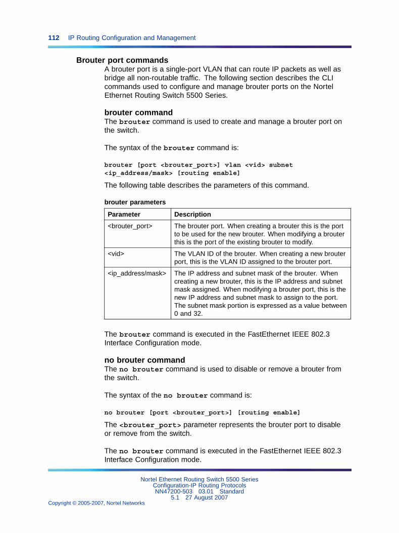
112 IP Routing Configuration and Management
Brouter port commandsA brouter port is a single-port VLAN that can route IP packets as well asbridge all non-routable traffic. The following section describes the CLIcommands used to configure and manage brouter ports on the NortelEthernet Routing Switch 5500 Series.
brouter commandThe brouter command is used to create and manage a brouter port onthe switch.
The syntax of the brouter command is:
brouter [port <brouter_port>] vlan <vid> subnet<ip_address/mask> [routing enable]
The following table describes the parameters of this command.
brouter parameters
Parameter Description
<brouter_port> The brouter port. When creating a brouter this is the portto be used for the new brouter. When modifying a brouterthis is the port of the existing brouter to modify.
<vid> The VLAN ID of the brouter. When creating a new brouterport, this is the VLAN ID assigned to the brouter port.
<ip_address/mask> The IP address and subnet mask of the brouter. Whencreating a new brouter, this is the IP address and subnetmask assigned. When modifying a brouter port, this is thenew IP address and subnet mask to assign to the port.The subnet mask portion is expressed as a value between0 and 32.
The brouter command is executed in the FastEthernet IEEE 802.3Interface Configuration mode.
no brouter commandThe no brouter command is used to disable or remove a brouter fromthe switch.
The syntax of the no brouter command is:
no brouter [port <brouter_port>] [routing enable]
The <brouter_port> parameter represents the brouter port to disableor remove from the switch.
The no brouter command is executed in the FastEthernet IEEE 802.3Interface Configuration mode.
Nortel Ethernet Routing Switch 5500 SeriesConfiguration-IP Routing ProtocolsNN47200-503 03.01 Standard
5.1 27 August 2007Copyright © 2005-2007, Nortel Networks
.
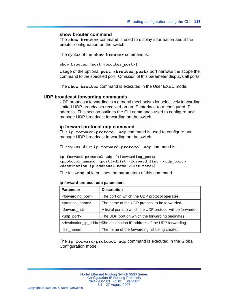
IP routing configuration using the CLI 113
show brouter commandThe show brouter command is used to display information about thebrouter configuration on the switch.
The syntax of the show brouter command is:
show brouter [port <brouter_port>]
Usage of the optional port <brouter_port> port narrows the scope thecommand to the specified port. Omission of this parameter displays all ports.
The show brouter command is executed in the User EXEC mode.
UDP broadcast forwarding commandsUDP broadcast forwarding is a general mechanism for selectively forwardinglimited UDP broadcasts received on an IP interface to a configured IPaddress. This section outlines the CLI commands used to configure andmanage UDP broadcast forwarding on the switch.
ip forward-protocol udp commandThe ip forward-protocol udp command is used to configure andmanage UDP broadcast forwarding on the switch.
The syntax of the ip forward-protocol udp command is:
ip forward-protocol udp [<forwarding_port><protocol_name>] [portfwdlist <forward_list> <udp_port><destination_ip_address> name <list_name>]
The following table outlines the parameters of this command.
ip forward-protocol udp parameters
Parameter Description
<forwarding_port> The port on which the UDP protocol operates.
<protocol_name> The name of the UDP protocol to be forwarded.
<forward_list> A list of ports to which the UDP protocol will be forwarded.
<udp_port> The UDP port on which the forwarding originates.
<destination_ip_address>The destination IP address of the UDP forwarding.
<list_name> The name of the forwarding list being created.
The ip forward-protocol udp command is executed in the GlobalConfiguration mode.
Nortel Ethernet Routing Switch 5500 SeriesConfiguration-IP Routing ProtocolsNN47200-503 03.01 Standard
5.1 27 August 2007Copyright © 2005-2007, Nortel Networks
.
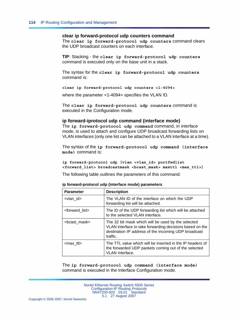
114 IP Routing Configuration and Management
clear ip forward-protocol udp counters commandThe clear ip forward-protocol udp counters command clearsthe UDP broadcast counters on each interface.
TIP: Stacking - the clear ip forward-protocol udp counterscommand is executed only on the base unit in a stack.
The syntax for the clear ip forward-protocol udp counterscommand is:
clear ip forward-protocol udp counters <1-4094>
where the parameter <1-4094> specifies the VLAN ID.
The clear ip forward-protocol udp counters command isexecuted in the Configuration mode.
ip forward-iprotocol udp command (interface mode)The ip forward-protocol udp command command, in interfacemode, is used to attach and configure UDP broadcast forwarding lists onVLAN interfaces (only one list can be attached to a VLAN interface at a time).
The syntax of the ip forward-protocol udp command (interfacemode) command is:
ip forward-protocol udp [vlan <vlan_id> portfwdlist<forward_list> broadcastmask <bcast_mask> maxttl <max_ttl>]
The following table outlines the parameters of this command:
ip forward-protocol udp (interface mode) parameters
Parameter Description
<vlan_id> The VLAN ID of the interface on which the UDPforwarding list will be attached.
<forward_list> The ID of the UDP forwarding list which will be attachedto the selected VLAN interface.
<bcast_mask> The 32 bit mask which will be used by the selectedVLAN interface to take forwarding decisions based on thedestination IP address of the incoming UDP broadcasttraffic.
<max_ttl> The TTL value which will be inserted in the IP headers ofthe forwarded UDP packets coming out of the selectedVLAN interface.
The ip forward-protocol udp command (interface mode)command is executed in the Interface Configuration mode.
Nortel Ethernet Routing Switch 5500 SeriesConfiguration-IP Routing ProtocolsNN47200-503 03.01 Standard
5.1 27 August 2007Copyright © 2005-2007, Nortel Networks
.
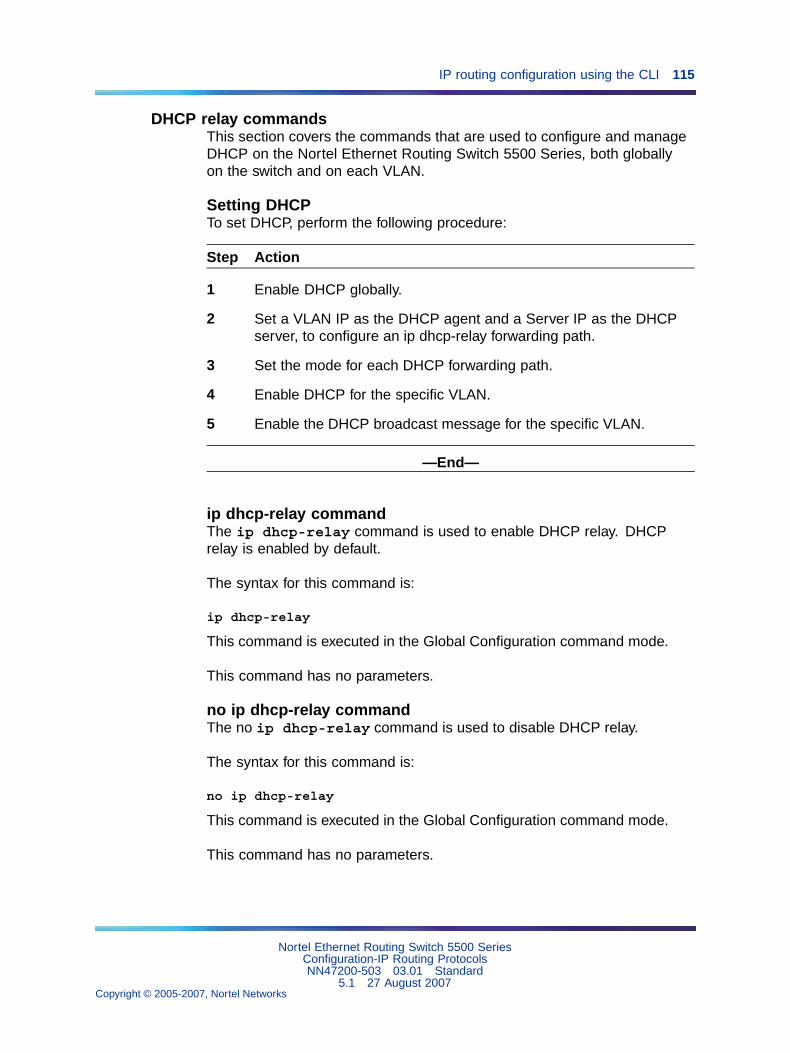
IP routing configuration using the CLI 115
DHCP relay commandsThis section covers the commands that are used to configure and manageDHCP on the Nortel Ethernet Routing Switch 5500 Series, both globallyon the switch and on each VLAN.
Setting DHCPTo set DHCP, perform the following procedure:
Step Action
1 Enable DHCP globally.
2 Set a VLAN IP as the DHCP agent and a Server IP as the DHCPserver, to configure an ip dhcp-relay forwarding path.
3 Set the mode for each DHCP forwarding path.
4 Enable DHCP for the specific VLAN.
5 Enable the DHCP broadcast message for the specific VLAN.
—End—
ip dhcp-relay commandThe ip dhcp-relay command is used to enable DHCP relay. DHCPrelay is enabled by default.
The syntax for this command is:
ip dhcp-relay
This command is executed in the Global Configuration command mode.
This command has no parameters.
no ip dhcp-relay commandThe no ip dhcp-relay command is used to disable DHCP relay.
The syntax for this command is:
no ip dhcp-relay
This command is executed in the Global Configuration command mode.
This command has no parameters.
Nortel Ethernet Routing Switch 5500 SeriesConfiguration-IP Routing ProtocolsNN47200-503 03.01 Standard
5.1 27 August 2007Copyright © 2005-2007, Nortel Networks
.
116 IP Routing Configuration and Management
show ip dhcp-relay counters commandThe show ip dhcp-relay counters command displays the currentDHCP relay counters configuration globally on the Nortel Ethernet RoutingSwitch 5500 Series. This includes the number of requests and the numberof replies.
The syntax for the show ip dhcp-relay counters command is:
show ip dhcp-relay counters
The show ip dhcp-relay counters command is executed in the UserEXEC command mode.
ip dhcp-relay clear-countersThe ip dhcp-relay clear-counters command clears the countersfor an interface.
The syntax for this command is:
ip dhcp-relay clear-counters
This command is executed in the Interface Configuration command modewhile editing a VLAN only.
This command has no parameters.
show ip dhcp-relay fwd-path commandThe show ip dhcp-relay fwd-path command displays the currentDHCP relay forward path configuration globally on the Nortel EthernetRouting Switch 5500 Series which includes the interface, the server, thestate (enabled or disabled), and the mode.
The syntax for the show ip dhcp-relay fwd-path command is:
show ip dhcp-relay fwd-path
The show ip dhcp-relay fwd-path command is executed in the UserEXEC command mode.
ip dhcp-relay fwd-path commandThe ip dhcp-relay fwd-path command sets the mode for the specificforwarding path DHCP relay settings globally on the Nortel Ethernet RoutingSwitch 5500 Series.
The syntax for the ip dhcp-relay fwd-path command is:
ip dhcp-relay fwd-path <A.B.C.D> <O.P.Q.R>
The following table outlines the parameters for this command.
Nortel Ethernet Routing Switch 5500 SeriesConfiguration-IP Routing ProtocolsNN47200-503 03.01 Standard
5.1 27 August 2007Copyright © 2005-2007, Nortel Networks
.
IP routing configuration using the CLI 117
ip dhcp-relay fwd-path parameters
Parameter Description
<A.B.C.D> Enter the IP address of the DHCP agent on theforwarding path to be configured.
<O.P.Q.R> Enter the IP address of the DHCP server on theforwarding path to be configured.
The ip dhcp-relay fwd-path command is executed in the GlobalConfiguration command mode.
The DHCP relay feature is enabled by default, and the default mode isBootP-DHCP.
ip dhcp-relay fwd-path enable commandThe ip dhcp-relay fwd-path enable command enables the specificDHCP forwarding path globally on the Nortel Ethernet Routing Switch 5500Series.
The syntax for the ip dhcp-relay fwd-path enable command is:
ip dhcp-relay fwd-path <A.B.C.D> <O.P.Q.R> enable
The following table describes the parameters for this command.
ip dhcp-relay fwd-path enable parameters
Parameter Description
<A.B.C.D> Enter the IP address of the DHCP agent on theforwarding path to be enabled.
<O.P.Q.R> Enter the IP address of the DHCP server on theforwarding path to be enabled.
The ip dhcp-relay fwd-path enable command is executed in theGlobal Configuration command mode.
The DHCP feature is enabled by default.
ip dhcp-relay fwd-path disable commandThe ip dhcp-relay fwd-path disable command disables thespecific DHCP forwarding path globally on the Nortel Ethernet RoutingSwitch 5500 Series.
The syntax for the ip dhcp-relay fwd-path disable command is:
ip dhcp-relay fwd-path <A.B.C.D> <O.P.Q.R> disable
Nortel Ethernet Routing Switch 5500 SeriesConfiguration-IP Routing ProtocolsNN47200-503 03.01 Standard
5.1 27 August 2007Copyright © 2005-2007, Nortel Networks
.
118 IP Routing Configuration and Management
The following table describes the parameters for this command.
ip dhcp-relay fwd-path disable parameters
Parameter Description
<A.B.C.D> Enter the IP address of the DHCP agent on theforwarding path to be disabled.
<O.P.Q.R> Enter the IP address of the DHCP server on theforwarding path to be disabled.
The ip dhcp-relay fwd-path disable command is executed in theGlobal Configuration command mode.
The DHCP relay feature is enabled by default.
no ip dhcp-relay fwd-path commandThe no ip dhcp-relay fwd-path command removes the specifiedDHCP forwarding path globally on the Nortel Ethernet Routing Switch 5500Series.
The syntax for the no ip dhcp-relay fwd-path command is:
no ip dhcp-relay fwd-path <A.B.C.D> <O.P.Q.R>
The following table outlines the parameters for this command.
no ip dhcp-relay fwd-path parameters
Parameter Description
<A.B.C.D> Enter the IP address of the DHCP agent on theforwarding path to be removed.
<O.P.Q.R> Enter the IP address of the DHCP server on theforwarding path to be removed.
The no ip dhcp-relay fwd-path command is executed in the GlobalConfiguration command mode.
show vlan dhcp-relay commandThe show vlan dhcp-relay command displays the current DHCP relayforward path configuration for each VLAN on the Nortel Ethernet RoutingSwitch 5500 Series.
The syntax for the show vlan dhcp-relay command is:
show vlan dhcp-relay [<1-4094>]
Substitute <1-4094> above with the VLAN ID of the VLAN to be displayed.
Nortel Ethernet Routing Switch 5500 SeriesConfiguration-IP Routing ProtocolsNN47200-503 03.01 Standard
5.1 27 August 2007Copyright © 2005-2007, Nortel Networks
.
IP routing configuration using the CLI 119
The show vlan dhcp-relay command is executed in the User EXECcommand mode.
ip dhcp-relay commandThe ip dhcp-relay command allows configures DHCP relay settingson a VLAN.
The syntax for the ip dhcp-relay command is:
ip dhcp-relay [min-sec <0-65535>] [mode {bootp | dhcp |bootp_dhcp}]
The following table outlines the parameters for this command.
ip dhcp-relay parameters
Parameter Description
min-sec <0-65535> Enter the minimum number of seconds to waitbetween receiving the DHCP packet and forwardingit to the destination device. The default is 0.
mode {bootp | dhcp |bootp_dhcp}
Enter the type of DHCP packets this VLAN supports:
• bootp - Supports BootP only
• dhcp - Supports DHCP only
• bootp_dhcp - Supports both BootP and DHCP
The ip dhcp-relay command is executed in the Interface Configurationcommand mode.
no ip dhcp-relay commandThe no ip dhcp-relay command disables DHCP relay on a VLAN.
The syntax for the no ip dhcp-relay command is:
no ip dhcp-relay
The no ip dhcp-relay command is executed in the InterfaceConfiguration command mode.
ip dhcp-relay broadcast commandThe ip dhcp-relay broadcast command enables DHCP relaybroadcast on a VLAN.
The syntax for the ip dhcp-relay broadcast command is:
Nortel Ethernet Routing Switch 5500 SeriesConfiguration-IP Routing ProtocolsNN47200-503 03.01 Standard
5.1 27 August 2007Copyright © 2005-2007, Nortel Networks
.
120 IP Routing Configuration and Management
ip dhcp-relay broadcast
The ip dhcp-relay broadcast command is executed in the InterfaceConfiguration command mode.
no ip dhcp-relay broadcast commandThe no ip dhcp-relay broadcast command disables DHCP relaybroadcast on a VLAN.
The syntax for the no ip dhcp-relay broadcast command is:
no ip dhcp-relay broadcast
The no ip dhcp-relay broadcast command is executed in theInterface Configuration command mode.
IP routing configuration examplesThis section provides configuration examples for common IP routing tasksusing the Command Line Interface (CLI). For conceptual information aboutthe IP routing topics covered in this section, refer to "An Introduction to IPRouting Protocols" (page 13).
Note: In many of the following configuration examples, a brouter portis used to create a connection to the network core. This practice doesnot imply that a brouter port is the only means through which a coreconnection can be established. The use of a brouter port is only one ofmany ways to create such a connection.
Address Resolution Protocol (ARP) configurationThe Nortel Ethernet Routing Switch 5500 Series provides the followingAddress Resolution Protocol (ARP) features:
• Default ARP aging
• Static ARP entries
• Proxy ARP
Static ARP entries can be used to solve the following instances encounteredon many networks:
• To communicate with a device that does not respond to an ARP request.
• To prevent an existing ARP entry from aging out.
When a static ARP entry is configured, both the IP address and MACaddress of a device is assigned to a physical port. This includes the VLANnumber if the physical port is associated with a VLAN.
Nortel Ethernet Routing Switch 5500 SeriesConfiguration-IP Routing ProtocolsNN47200-503 03.01 Standard
5.1 27 August 2007Copyright © 2005-2007, Nortel Networks
.
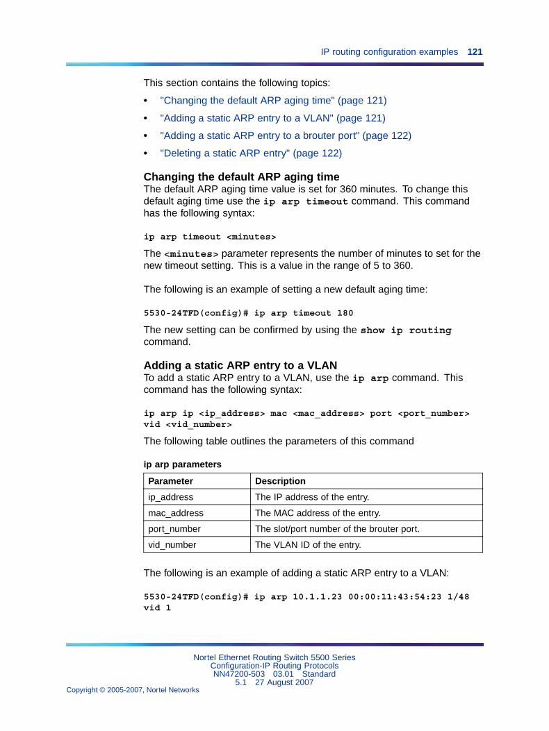
IP routing configuration examples 121
This section contains the following topics:
• "Changing the default ARP aging time" (page 121)
• "Adding a static ARP entry to a VLAN" (page 121)
• "Adding a static ARP entry to a brouter port" (page 122)
• "Deleting a static ARP entry" (page 122)
Changing the default ARP aging timeThe default ARP aging time value is set for 360 minutes. To change thisdefault aging time use the ip arp timeout command. This commandhas the following syntax:
ip arp timeout <minutes>
The <minutes> parameter represents the number of minutes to set for thenew timeout setting. This is a value in the range of 5 to 360.
The following is an example of setting a new default aging time:
5530-24TFD(config)# ip arp timeout 180
The new setting can be confirmed by using the show ip routingcommand.
Adding a static ARP entry to a VLANTo add a static ARP entry to a VLAN, use the ip arp command. Thiscommand has the following syntax:
ip arp ip <ip_address> mac <mac_address> port <port_number>vid <vid_number>
The following table outlines the parameters of this command
ip arp parameters
Parameter Description
ip_address The IP address of the entry.
mac_address The MAC address of the entry.
port_number The slot/port number of the brouter port.
vid_number The VLAN ID of the entry.
The following is an example of adding a static ARP entry to a VLAN:
5530-24TFD(config)# ip arp 10.1.1.23 00:00:11:43:54:23 1/48vid 1
Nortel Ethernet Routing Switch 5500 SeriesConfiguration-IP Routing ProtocolsNN47200-503 03.01 Standard
5.1 27 August 2007Copyright © 2005-2007, Nortel Networks
.
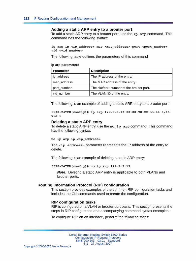
122 IP Routing Configuration and Management
Adding a static ARP entry to a brouter portTo add a static ARP entry to a brouter port, use the ip arp command. Thiscommand has the following syntax:
ip arp ip <ip_address> mac <mac_address> port <port_number>vid <vid_number>
The following table outlines the parameters of this command
ip arp parameters
Parameter Description
ip_address The IP address of the entry.
mac_address The MAC address of the entry.
port_number The slot/port number of the brouter port.
vid_number The VLAN ID of the entry.
The following is an example of adding a static ARP entry to a brouter port:
5530-24TFD(config)# ip arp 172.2.2.13 00:00:98:22:33:44 1/46vid 1
Deleting a static ARP entryTo delete a static ARP entry, use the no ip arp command. This commandhas the following syntax:
no ip arp ip <ip_address>
The <ip_address> parameter represents the IP address of the entry todelete.
The following is an example of deleting a static ARP entry:
5530-24TFD(config)# no ip arp 172.2.2.13
Note: Deleting a static ARP entry is applicable to both VLANs andbrouter ports.
Routing Information Protocol (RIP) configurationThis section provides examples of the common RIP configuration tasks andincludes the CLI commands used to create the configuration.
RIP configuration tasksRIP is configured on a VLAN or brouter port basis. This section presents thesteps in RIP configuration and accompanying command syntax examples.
To configure RIP on an interface, perform the following steps:
Nortel Ethernet Routing Switch 5500 SeriesConfiguration-IP Routing ProtocolsNN47200-503 03.01 Standard
5.1 27 August 2007Copyright © 2005-2007, Nortel Networks
.
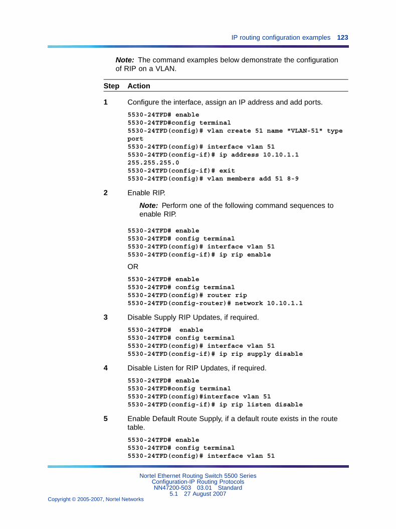
IP routing configuration examples 123
Note: The command examples below demonstrate the configurationof RIP on a VLAN.
Step Action
1 Configure the interface, assign an IP address and add ports.
5530-24TFD# enable5530-24TFD#config terminal5530-24TFD(config)# vlan create 51 name "VLAN-51" typeport5530-24TFD(config)# interface vlan 515530-24TFD(config-if)# ip address 10.10.1.1255.255.255.05530-24TFD(config-if)# exit5530-24TFD(config)# vlan members add 51 8-9
2 Enable RIP.
Note: Perform one of the following command sequences toenable RIP.
5530-24TFD# enable5530-24TFD# config terminal5530-24TFD(config)# interface vlan 515530-24TFD(config-if)# ip rip enable
OR
5530-24TFD# enable5530-24TFD# config terminal5530-24TFD(config)# router rip5530-24TFD(config-router)# network 10.10.1.1
3 Disable Supply RIP Updates, if required.
5530-24TFD# enable5530-24TFD# config terminal5530-24TFD(config)# interface vlan 515530-24TFD(config-if)# ip rip supply disable
4 Disable Listen for RIP Updates, if required.
5530-24TFD# enable5530-24TFD#config terminal5530-24TFD(config)#interface vlan 515530-24TFD(config-if)# ip rip listen disable
5 Enable Default Route Supply, if a default route exists in the routetable.
5530-24TFD# enable5530-24TFD# config terminal5530-24TFD(config)# interface vlan 51
Nortel Ethernet Routing Switch 5500 SeriesConfiguration-IP Routing ProtocolsNN47200-503 03.01 Standard
5.1 27 August 2007Copyright © 2005-2007, Nortel Networks
.
124 IP Routing Configuration and Management
5530-24TFD(config-if)# ip rip default-supply enable
6 Enable Default Route Listen to add a default route to the route table,if advertised from another router.
5530-24TFD# enable5530-24TFD# config terminal5530-24TFD(config)# interface vlan 515530-24TFD(config-if)# ip rip default-listen enable
7 Add the In or Out Route Policy.
5530-24TFD# enable5530-24TFD# config terminal5530-24TFD(config)# interface vlan 515530-24TFD(config-if)# ip rip out-policy map1
8 Enable Triggered Updates, if required.
5530-24TFD# enable5530-24TFD# config terminal5530-24TFD(config)# interface vlan 515530-24TFD(config-if)# ip rip triggered enable
9 Configure the cost of the link by entering a value of 1 to 15; where 1is the default.
5530-24TFD# enable5530-24TFD# config terminal5530-24TFD(config)# interface vlan 515530-24TFD(config-if)# ip rip cost 2
10 Configure send mode parameters.
5530-24TFD# enable5530-24TFD# config terminal5530-24TFD(config)# router rip enable5530-24TFD(config)# interface vlan 515530-24TFD(config-if)# ip rip send version rip2
11 Configure receive mode parameters.
5530-24TFD# enable5530-24TFD# config terminal5530-24TFD(config)# router rip enable5530-24TFD(config)# interface vlan 515530-24TFD(config-if)# ip rip receive version rip2
12 Enable poison reverse.
Note: RIP Split Horizon is enabled by default. By setting thePoison parameter to true, Poison Reverse is enabled. If PoisonReverse is enabled, the RIP updates sent to a neighbor fromwhich a route is learned are poisoned with a metric of 16.
Nortel Ethernet Routing Switch 5500 SeriesConfiguration-IP Routing ProtocolsNN47200-503 03.01 Standard
5.1 27 August 2007Copyright © 2005-2007, Nortel Networks
.
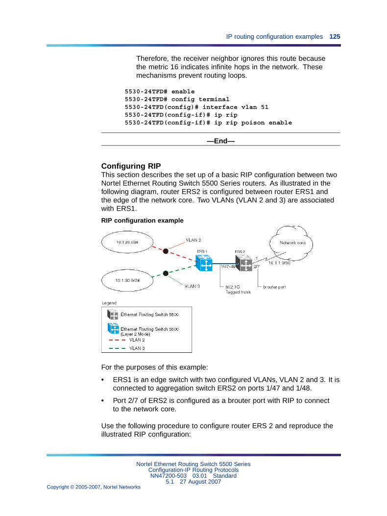
IP routing configuration examples 125
Therefore, the receiver neighbor ignores this route becausethe metric 16 indicates infinite hops in the network. Thesemechanisms prevent routing loops.
5530-24TFD# enable5530-24TFD# config terminal5530-24TFD(config)# interface vlan 515530-24TFD(config-if)# ip rip5530-24TFD(config-if)# ip rip poison enable
—End—
Configuring RIPThis section describes the set up of a basic RIP configuration between twoNortel Ethernet Routing Switch 5500 Series routers. As illustrated in thefollowing diagram, router ERS2 is configured between router ERS1 andthe edge of the network core. Two VLANs (VLAN 2 and 3) are associatedwith ERS1.
RIP configuration example
For the purposes of this example:
• ERS1 is an edge switch with two configured VLANs, VLAN 2 and 3. It isconnected to aggregation switch ERS2 on ports 1/47 and 1/48.
• Port 2/7 of ERS2 is configured as a brouter port with RIP to connectto the network core.
Use the following procedure to configure router ERS 2 and reproduce theillustrated RIP configuration:
Nortel Ethernet Routing Switch 5500 SeriesConfiguration-IP Routing ProtocolsNN47200-503 03.01 Standard
5.1 27 August 2007Copyright © 2005-2007, Nortel Networks
.
126 IP Routing Configuration and Management
Step Action
1 Configure tagging on ports 1/47 and 1/48. Tagging is required tosupport multiple VLANs on the same interface.
5530-24TFD# enable5530-24TFD# config terminal5530-24TFD(config)# vlan ports 1/47-48 tagging tagAll
2 Configure ERS2 for VLAN 2 access.
a. Create a port-based VLAN (VLAN 2) using spanning tree group1 and include ports 1/47 and 1/48 in VLAN 2.
5530-24TFD(config)# vlan create 2 name "VLAN-2" typeport5530-24TFD(config)# vlan member add 2 port 1/47-48
b. Assign the IP address 10.1.20.2/24 to VLAN 2.
5530-24TFD(config)# interface vlan 25530-24TFD(config-if)# ip address 10.1.20.2255.255.255.0
c. Enable RIP for VLAN 2 and disable RIP supply and listen. RIPsupply and listen are not required because no router is attachedto VLAN 2.
5530-24TFD(config)# interface vlan 25530-24TFD(config-if)# ip rip enable5530-24TFD(config-if)# ip rip supply disable5530-24TFD(config-if)# ip rip listen disable
3 Configure ERS2 for VLAN 3 access.
a. Create a port-based VLAN (VLAN 3) using spanning tree group1 and include ports 1/47 and 1/48 in VLAN3.
5530-24TFD(config)# vlan create 3 name "VLAN-3" typeport5530-24TFD(config)# vlan member add 3 port 1/47-48
b. Assign the IP address 10.1.30.2/24 to VLAN 3.
5530-24TFD(config)# interface vlan 35530-24TFD(config-if)# ip address 10.1.30.2255.255.255.0
c. Enable RIP for VLAN 3 and disable RIP supply and listen. RIPsupply and listen are not required because no router is attachedto VLAN 3.
5530-24TFD(config)# interface vlan 35530-24TFD(config-if)# ip rip enable5530-24TFD(config-if)# ip rip supply disable
Nortel Ethernet Routing Switch 5500 SeriesConfiguration-IP Routing ProtocolsNN47200-503 03.01 Standard
5.1 27 August 2007Copyright © 2005-2007, Nortel Networks
.
IP routing configuration examples 127
5530-24TFD(config-if)#ip rip listen disable
4 Configure brouter port 2/7 on ERS2.
a. Assign the IP address 10.1.1.1/30 to port 2/7 using brouterVLAN 2090.
5530-24TFD(config)# interface FastEthernet 2/75530-24TFD(config-if)# brouter vlan 2090 subnet10.1.1.1/30
Note: Usage of the brouter command above requires theusage of Variable Length Subnetting. Usage of a dotteddecimal subnet mask is not allowed.
b. Enable RIP on the interface.
5530-24TFD(config)# interface FastEthernet 2/75530-24TFD(config-if)# ip rip enable
5 Enable IP routing and RIP globally.
5530-24TFD(config)# ip routing5530-24TFD(config)# router rip enable
—End—
A list of the commands used to create this configuration can be displayedusing the show running-config command. Using this command onERS2 would list the following commands:
! *** VLAN *** !vlan igmp unknown-mcast-no-flood disablevlan configcontrol strictauto-pvidvlan name 1 "VLAN #1"vlan create 2 name "VLAN-2" type portvlan create 3 name "VLAN-3" type portvlan members 2 1/47-48vlan members 3 1/47-48! *** RIP *** !router riprouter rip enabletimers basic holddown 120timers basic timeout 180 update 30 default-metric 8network 10.1.20.2network 10.1.30.2network 10.1.1.1interface vlan 2no ip rip listen enableno ip rip supply enable
Nortel Ethernet Routing Switch 5500 SeriesConfiguration-IP Routing ProtocolsNN47200-503 03.01 Standard
5.1 27 August 2007Copyright © 2005-2007, Nortel Networks
.
128 IP Routing Configuration and Management
interface vlan 3no ip rip listen enableno ip rip supply enable! *** Brouter Port *** !interface fastEthernet ALLbrouter port 2/7 vlan 3 subnet 10.1.1.1/30
The following commands can be used to confirm the configuration of RIPparameters:
Command Description
show vlan This command is used to display information about thecurrently configured switch VLANs.
show vlan ip This command is used to display IP address informationabout VLANs that have been assigned addresses on theswitch.
show ip rip This command displays information on the global switch RIPconfiguration.
show ip route This command displays the switch routing table.
show ip ripinterface
This command displays information about the RIP interfacespresent on the switch.
Configuring RIP version 2When RIP is enabled on an interface, it operates by default inrip1compatible send mode and rip1orRip2 receive mode. Depending onconfiguration requirements, the Nortel Ethernet Routing Switch 5500 Seriescan be configured to operate using RIP version 1 or 2. The configurationillustrated below demonstrates a Nortel Ethernet Routing Switch 5500Series switch that has been configured to operate use RIP version 2 only.
Note: This example builds on the previous RIP configuration.
Nortel Ethernet Routing Switch 5500 SeriesConfiguration-IP Routing ProtocolsNN47200-503 03.01 Standard
5.1 27 August 2007Copyright © 2005-2007, Nortel Networks
.
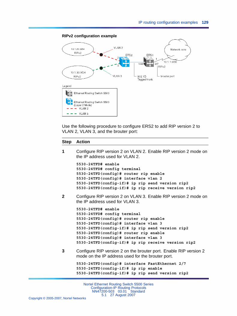
IP routing configuration examples 129
RIPv2 configuration example
Use the following procedure to configure ERS2 to add RIP version 2 toVLAN 2, VLAN 3, and the brouter port:
Step Action
1 Configure RIP version 2 on VLAN 2. Enable RIP version 2 mode onthe IP address used for VLAN 2.
5530-24TFD# enable5530-24TFD# config terminal5530-24TFD(config)# router rip enable5530-24TFD(config)# interface vlan 25530-24TFD(config-if)# ip rip send version rip25530-24TFD(config-if)# ip rip receive version rip2
2 Configure RIP version 2 on VLAN 3. Enable RIP version 2 mode onthe IP address used for VLAN 3.
5530-24TFD# enable5530-24TFD# config terminal5530-24TFD(config)# router rip enable5530-24TFD(config)# interface vlan 35530-24TFD(config-if)# ip rip send version rip25530-24TFD(config)# router rip enable5530-24TFD(config)# interface vlan 35530-24TFD(config-if)# ip rip receive version rip2
3 Configure RIP version 2 on the brouter port. Enable RIP version 2mode on the IP address used for the brouter port.
5530-24TFD(config)# interface FastEthernet 2/75530-24TFD(config-if)# ip rip enable5530-24TFD(config-if)# ip rip send version rip2
Nortel Ethernet Routing Switch 5500 SeriesConfiguration-IP Routing ProtocolsNN47200-503 03.01 Standard
5.1 27 August 2007Copyright © 2005-2007, Nortel Networks
.

130 IP Routing Configuration and Management
5530-24TFD(config-if)# ip rip receive version rip2
—End—
Using RIP accept policiesRIP accept policies are used on the Nortel Ethernet Routing Switch 5500Series to selectively accept routes from RIP updates. If no policies aredefined, the default behavior is applied. This default behavior is to add alllearned routes to the route table. RIP accept policies are used to:
• Listen to RIP updates only from certain gateways.
• Listen only for specific networks.
• Assign a specific mask to be included with a network in the routing table(such as a network summary).
In the configuration illustrated below, the Nortel Ethernet Routing Switch5500 Series (ERS1) is configured with a RIP accept policy. This creates asingle route directed to ERS3 for all networks configured on it. The acceptpolicy accepts any network from 10.1.240.0 to 10.1.255.0, and creates asingle entry in the routing table on ERS1.
A summary route is calculated by comparing the common bits in theaddress range to derive the summary address. For example, if the range ofIP addresses is from 10.1.240.0 to 10.1.255.0:
1. Determine the third octet of the first address: 10.1.240.0 = 1111 0000.
2. Determine the third octet of the ending address: 10.1.255.0 = 11111111.
3. Extract the common bits: 240 = 1111 0000 255 = 1111 1111 1111= 20 bit mask.
Therefore, the network address to use for this example is 10.1.240.0/20
Nortel Ethernet Routing Switch 5500 SeriesConfiguration-IP Routing ProtocolsNN47200-503 03.01 Standard
5.1 27 August 2007Copyright © 2005-2007, Nortel Networks
.
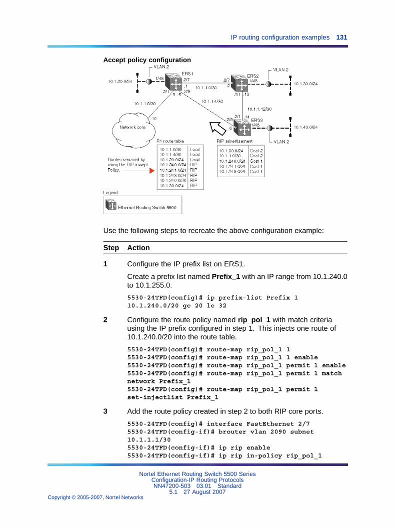
IP routing configuration examples 131
Accept policy configuration
Use the following steps to recreate the above configuration example:
Step Action
1 Configure the IP prefix list on ERS1.
Create a prefix list named Prefix_1 with an IP range from 10.1.240.0to 10.1.255.0.
5530-24TFD(config)# ip prefix-list Prefix_110.1.240.0/20 ge 20 le 32
2 Configure the route policy named rip_pol_1 with match criteriausing the IP prefix configured in step 1. This injects one route of10.1.240.0/20 into the route table.
5530-24TFD(config)# route-map rip_pol_1 15530-24TFD(config)# route-map rip_pol_1 1 enable5530-24TFD(config)# route-map rip_pol_1 permit 1 enable5530-24TFD(config)# route-map rip_pol_1 permit 1 matchnetwork Prefix_15530-24TFD(config)# route-map rip_pol_1 permit 1set-injectlist Prefix_1
3 Add the route policy created in step 2 to both RIP core ports.
5530-24TFD(config)# interface FastEthernet 2/75530-24TFD(config-if)# brouter vlan 2090 subnet10.1.1.1/305530-24TFD(config-if)# ip rip enable5530-24TFD(config-if)# ip rip in-policy rip_pol_1
Nortel Ethernet Routing Switch 5500 SeriesConfiguration-IP Routing ProtocolsNN47200-503 03.01 Standard
5.1 27 August 2007Copyright © 2005-2007, Nortel Networks
.
132 IP Routing Configuration and Management
5530-24TFD(config)# interface FastEthernet 2/85530-24TFD(config-if)# brouter vlan 2091 subnet10.1.1.5/305530-24TFD(config-if)# ip rip enable5530-24TFD(config-if)# ip rip in-policy rip_pol_1
—End—
The show running-config command is used to display the currentconfiguration of a switch. Using this command on the above configurationwould yield the following results:
rip_pol_1! *** Route Policies *** !ip prefix-list Prefix_1 10.1.240.0/20 ge 20 le 32route-map rip_pol_1route-map rip_pol_1 1 enableno route-map rip_pol_1 1 match interfaceroute-map rip_pol_1 1 match metric 0route-map rip_pol_1 1 match network Prefix_1no route-map rip_pol_1 1 match next-hoproute-map rip_pol_1 1 match route-type anyno route-map rip_pol_1 match route-sourceroute-map rip_pol_1 1 set injectlist Prefix_1route-map rip_pol_1 set mask 0.0.0.0route-map rip_pol_1 set metric 0route-map rip_pol_1 set nssa-pbit enableroute-map rip_pol_1 set ip-preference 0! *** Brouter Port *** !interface fastEthernet ALLbrouter port 2/7vlan 2090 subnet 10.1.1.1/30ip rip in-policy rip_pol_1brouter port 2/8 vlan 2091 subnet 10.1.1.5/30ip rip in-policy rip_pol_1
Using RIP announce policiesIn the previous configuration example, a RIP accept policy is used on ERS1to insert a single route into its route table for all networks from ERS3.Instead of using an accept policy on ERS1, a RIP announce policy on ERS3could be used to announce a single route to both ERS1 and ERS2 for thelocal network range.
To configure the RIP announce policy on ERS3, use the followingconfiguration steps:
Nortel Ethernet Routing Switch 5500 SeriesConfiguration-IP Routing ProtocolsNN47200-503 03.01 Standard
5.1 27 August 2007Copyright © 2005-2007, Nortel Networks
.
IP routing configuration examples 133
Step Action
1 Configure the IP prefix list on ERS3 named Prefix_1 with the IPaddress 10.1.240.0.
5530-24TFD(config)# ip prefix-list Prefix_110.1.240.0/20 ge 20 le 32
2 Configure the route policy named Policy_Rip with match criteriausing the IP prefix configured in step 1.
5530-24TFD(config)# route-map rip_pol_1 15530-24TFD(config)# route-map rip_pol_1 1 enable5530-24TFD(config)# route-map rip_pol_1 permit 1 enable5530-24TFD(config)# route-map rip_pol_1 permit 1set-injectlist Prefix_1
3 Add the route policy created in step 2 to both RIP core ports.
5530-24TFD(config)# interface FastEthernet 2/15530-24TFD(config-if)# brouter vlan 2091 subnet10.1.1.14/305530-24TFD(config-if)# ip rip enable5530-24TFD(config-if)# ip rip out-policy rip_pol_15530-24TFD(config)# interface FastEthernet 2/85530-24TFD(config-if)# brouter vlan 2090 subnet10.1.1.6/305530-24TFD(config-if)# ip rip enable5530-24TFD(config-if)# ip rip out-policy rip_pol_1
—End—
To limit the advertising of routes using the announce policy from the routingtable, a route policy should be created to deny the route. To configure theRIP announce policy with a limited announce policy on ERS3, use thefollowing configuration steps:
Step Action
1 Configure the IP prefix list named Prefix_2 with the IP address10.1.240.0.
5530-24TFD(config)# ip prefix-list Prefix_210.1.240.0/20 ge 20 le 20
2 Configure the IP route policy named rip_pol_2 with match criteriausing the IP prefix configured in Step 1.
5530-24TFD(config)# route-map rip_pol_2 deny 1enable match network Prefix_2
Nortel Ethernet Routing Switch 5500 SeriesConfiguration-IP Routing ProtocolsNN47200-503 03.01 Standard
5.1 27 August 2007Copyright © 2005-2007, Nortel Networks
.
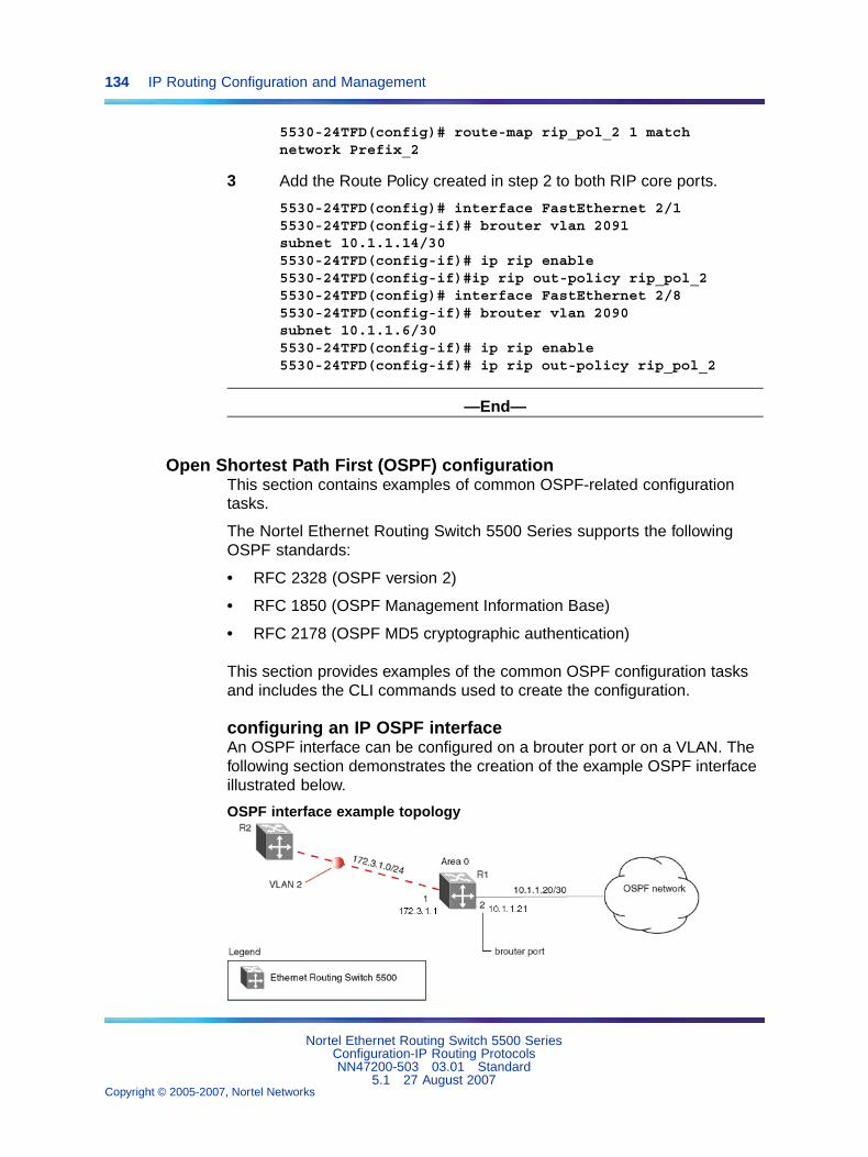
134 IP Routing Configuration and Management
5530-24TFD(config)# route-map rip_pol_2 1 matchnetwork Prefix_2
3 Add the Route Policy created in step 2 to both RIP core ports.
5530-24TFD(config)# interface FastEthernet 2/15530-24TFD(config-if)# brouter vlan 2091subnet 10.1.1.14/305530-24TFD(config-if)# ip rip enable5530-24TFD(config-if)#ip rip out-policy rip_pol_25530-24TFD(config)# interface FastEthernet 2/85530-24TFD(config-if)# brouter vlan 2090subnet 10.1.1.6/305530-24TFD(config-if)# ip rip enable5530-24TFD(config-if)# ip rip out-policy rip_pol_2
—End—
Open Shortest Path First (OSPF) configurationThis section contains examples of common OSPF-related configurationtasks.
The Nortel Ethernet Routing Switch 5500 Series supports the followingOSPF standards:
• RFC 2328 (OSPF version 2)
• RFC 1850 (OSPF Management Information Base)
• RFC 2178 (OSPF MD5 cryptographic authentication)
This section provides examples of the common OSPF configuration tasksand includes the CLI commands used to create the configuration.
configuring an IP OSPF interfaceAn OSPF interface can be configured on a brouter port or on a VLAN. Thefollowing section demonstrates the creation of the example OSPF interfaceillustrated below.
OSPF interface example topology
Nortel Ethernet Routing Switch 5500 SeriesConfiguration-IP Routing ProtocolsNN47200-503 03.01 Standard
5.1 27 August 2007Copyright © 2005-2007, Nortel Networks
.
IP routing configuration examples 135
To create the OSPF interface illustrated above for router R1, follow thisprocedure:
Step Action
1 Configure brouter port OSPF interface.
Configure port 2 as a brouter port with VLAN ID of 2134 and enableOSPF on this interface.
5530-24TFD# config terminal5530-24TFD(config)# interface fast 25530-24TFD(config-if)# brouter port 2 vlan 2134 subnet10.1.1.21/305530-24TFD(config-if)# router ospf5530-24TFD(config-router)# network 10.1.1.21
2 Configure the VLAN OSPF interface.
Create a port-based VLAN (VLAN 2) using spanning tree group1, assign IP address 172.3.1.1 to VLAN 2 and enable OSPF onthis interface.
5530-24TFD(config)# vlan create 2 type port5530-24TFD(config)# spanning-tree stp 1 add-vlan 25530-24TFD(config)# vlan member add 2 15530-24TFD(config)# interface vlan 25530-24TFD(config-if)# ip address 172.3.1.1255.255.255.05530-24TFD(config-if)# router ospf5530-24TFD(config-router)# network 172.3.1.1
3 Assign a router ID to the new interface and enable OSPF globally.
5530-24TFD(config)# router ospf5530-24TFD(config-router)# router-id 1.1.1.15530-24TFD(config-router)# exit5530-24TFD(config)# router ospf enable
—End—
OSPF securityThe Nortel Ethernet Routing Switch 5500 Series implementation of OSPFincludes security mechanisms to prevent the OSPF routing domain frombeing attacked by unauthorized routers. These security mechanismsprevent a malicious person from joining an OSPF domain and advertisingfalse information in its OSPF link state advertisements. Likewise, thesecurity prevents a misconfigured router from joining an OSPF domain.Currently there are two security mechanisms supported: simple passwordsecurity and Message Digest 5 (MD5) security.
Nortel Ethernet Routing Switch 5500 SeriesConfiguration-IP Routing ProtocolsNN47200-503 03.01 Standard
5.1 27 August 2007Copyright © 2005-2007, Nortel Networks
.
136 IP Routing Configuration and Management
Simple password mechanism The simple password security mechanismtransmits a text password in the OSPF headers. Only routers that containthe same authentication ID in their OSPF headers can communicate witheach other.
Note: Nortel recommends not using this security mechanismbecause the password is stored in plain text and can be read from theconfiguration file or from the OSPF packet.
To configure this authentication type on an OSPF interface of VLAN 2 usingthe password test1234, use the following commands:
5530-24TFD(config)# interface vlan 25530-24TFD(config-if)# ip ospf authentication-type simple5530-24TFD(config-if)# ip ospf authentication-key test1234
Message Digest 5 The Message Digest 5 (MD5) mechanism provides128-bit encrypted authentication based on the RFC 1321 standard. MD5authentication for OSPF security, makes it very hard for a malicious userto compute or extrapolate the decrypting codes from the OSPF packets.Basically, each OSPF packet has a message digest appended to it, whichneeds to be matched between sending and receiving routers. The messagedigest is calculated on either side, based on the MD5 Key and any padding,then compared for a match. If the message digest does not meet the matchcriteria, the packet is rejected.
Each OSPF interface supports up to 2 keys, identifiable by key ID, tofacilitate a smooth key transition during the rollover process. Only theselected primary key is used to encrypt the OSPF transmit packets.
The process of key change is as follows:
Note: Assume that all routers already use the same key forauthentication and a new key is required.
1. Add the second key to all routers. The routers will continue to sendOSPF packets encrypted with the old key.
2. Activate the second key on all routers by setting it as the primary key.Routers will send OSPF packets encrypted with the new key while stillaccepting packets using the old key. This is necessary as some routerswill not have activated the new key.
3. Remove the old key when all routers activate the new key.
MD5 configuration example In the configuration example illustratedbelow, MD5 is configured between router R1 and R2.
Nortel Ethernet Routing Switch 5500 SeriesConfiguration-IP Routing ProtocolsNN47200-503 03.01 Standard
5.1 27 August 2007Copyright © 2005-2007, Nortel Networks
.
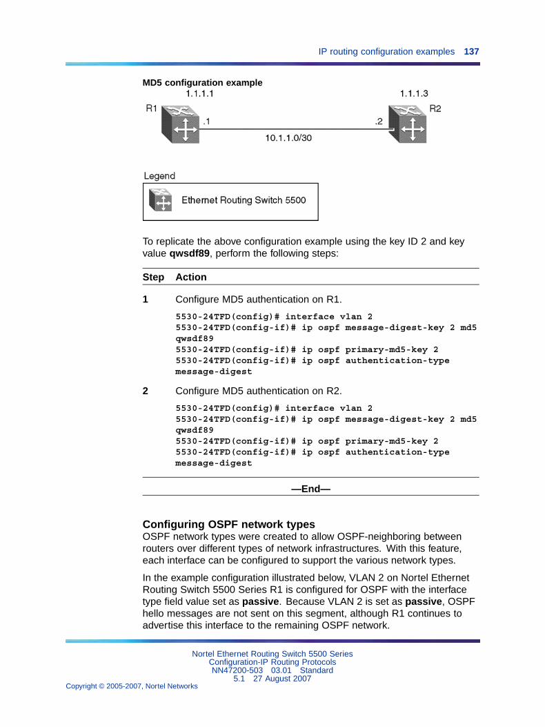
IP routing configuration examples 137
MD5 configuration example
To replicate the above configuration example using the key ID 2 and keyvalue qwsdf89, perform the following steps:
Step Action
1 Configure MD5 authentication on R1.
5530-24TFD(config)# interface vlan 25530-24TFD(config-if)# ip ospf message-digest-key 2 md5qwsdf895530-24TFD(config-if)# ip ospf primary-md5-key 25530-24TFD(config-if)# ip ospf authentication-typemessage-digest
2 Configure MD5 authentication on R2.
5530-24TFD(config)# interface vlan 25530-24TFD(config-if)# ip ospf message-digest-key 2 md5qwsdf895530-24TFD(config-if)# ip ospf primary-md5-key 25530-24TFD(config-if)# ip ospf authentication-typemessage-digest
—End—
Configuring OSPF network typesOSPF network types were created to allow OSPF-neighboring betweenrouters over different types of network infrastructures. With this feature,each interface can be configured to support the various network types.
In the example configuration illustrated below, VLAN 2 on Nortel EthernetRouting Switch 5500 Series R1 is configured for OSPF with the interfacetype field value set as passive. Because VLAN 2 is set as passive, OSPFhello messages are not sent on this segment, although R1 continues toadvertise this interface to the remaining OSPF network.
Nortel Ethernet Routing Switch 5500 SeriesConfiguration-IP Routing ProtocolsNN47200-503 03.01 Standard
5.1 27 August 2007Copyright © 2005-2007, Nortel Networks
.
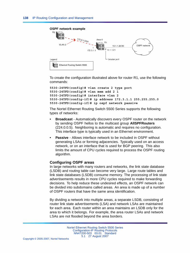
138 IP Routing Configuration and Management
OSPF network example
To create the configuration illustrated above for router R1, use the followingcommands:
5530-24TFD(config)# vlan create 2 type port5530-24TFD(config)# vlan mem add 2 15530-24TFD(config)# interface vlan 25530-24TFD(config-if)# ip address 172.3.1.1 255.255.255.05530-24TFD(config-if)# ip ospf network passive
The Nortel Ethernet Routing Switch 5500 Series supports the followingtypes of networks:
• Broadcast - Automatically discovers every OSPF router on the networkby sending OSPF hellos to the multicast group AllSPFRouters(224.0.0.5). Neighboring is automatic and requires no configuration.This interface type is typically used in an Ethernet environment.
• Passive - Allows interface network to be included in OSPF withoutgenerating LSAs or forming adjacencies. Typically used on an accessnetwork, or on an interface that is used for BGP peering. This alsolimits the amount of CPU cycles required to process the OSPF routingalgorithm.
Configuring OSPF areasIn large networks with many routers and networks, the link state database(LSDB) and routing table can become very large. Large route tables andlink state databases (LSDB) consume memory. The processing of link stateadvertisements results in more CPU cycles required to make forwardingdecisions. To help reduce these undesired effects, an OSPF network canbe divided into subdomains called areas. An area is made up of a numberof OSPF routers that have the same area identification.
By dividing a network into multiple areas, a separate LSDB, consisting ofrouter link state advertisements (LSA) and network LSAs are maintainedfor each area. Each router within an area maintains an LSDB only for thearea to which it belongs. For example, the area router LSAs and networkLSAs are not flooded beyond the area borders.
Nortel Ethernet Routing Switch 5500 SeriesConfiguration-IP Routing ProtocolsNN47200-503 03.01 Standard
5.1 27 August 2007Copyright © 2005-2007, Nortel Networks
.
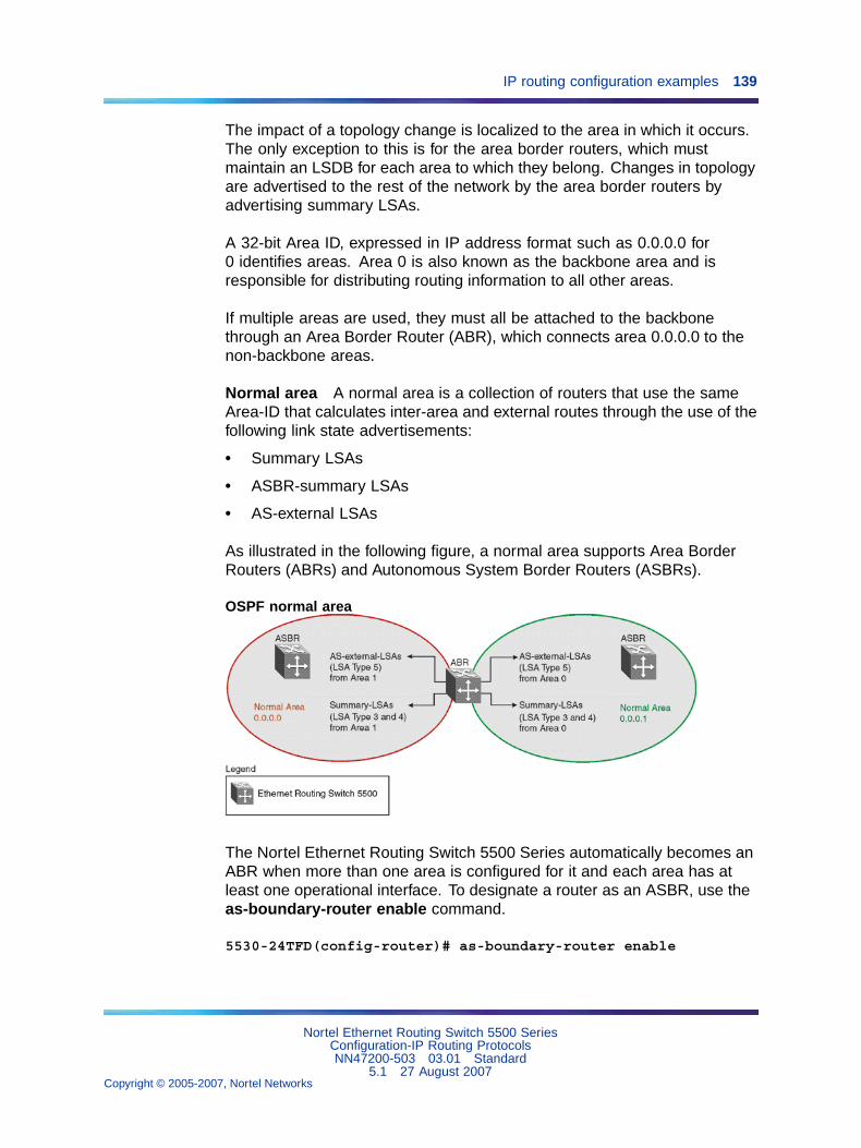
IP routing configuration examples 139
The impact of a topology change is localized to the area in which it occurs.The only exception to this is for the area border routers, which mustmaintain an LSDB for each area to which they belong. Changes in topologyare advertised to the rest of the network by the area border routers byadvertising summary LSAs.
A 32-bit Area ID, expressed in IP address format such as 0.0.0.0 for0 identifies areas. Area 0 is also known as the backbone area and isresponsible for distributing routing information to all other areas.
If multiple areas are used, they must all be attached to the backbonethrough an Area Border Router (ABR), which connects area 0.0.0.0 to thenon-backbone areas.
Normal area A normal area is a collection of routers that use the sameArea-ID that calculates inter-area and external routes through the use of thefollowing link state advertisements:
• Summary LSAs
• ASBR-summary LSAs
• AS-external LSAs
As illustrated in the following figure, a normal area supports Area BorderRouters (ABRs) and Autonomous System Border Routers (ASBRs).
OSPF normal area
The Nortel Ethernet Routing Switch 5500 Series automatically becomes anABR when more than one area is configured for it and each area has atleast one operational interface. To designate a router as an ASBR, use theas-boundary-router enable command.
5530-24TFD(config-router)# as-boundary-router enable
Nortel Ethernet Routing Switch 5500 SeriesConfiguration-IP Routing ProtocolsNN47200-503 03.01 Standard
5.1 27 August 2007Copyright © 2005-2007, Nortel Networks
.
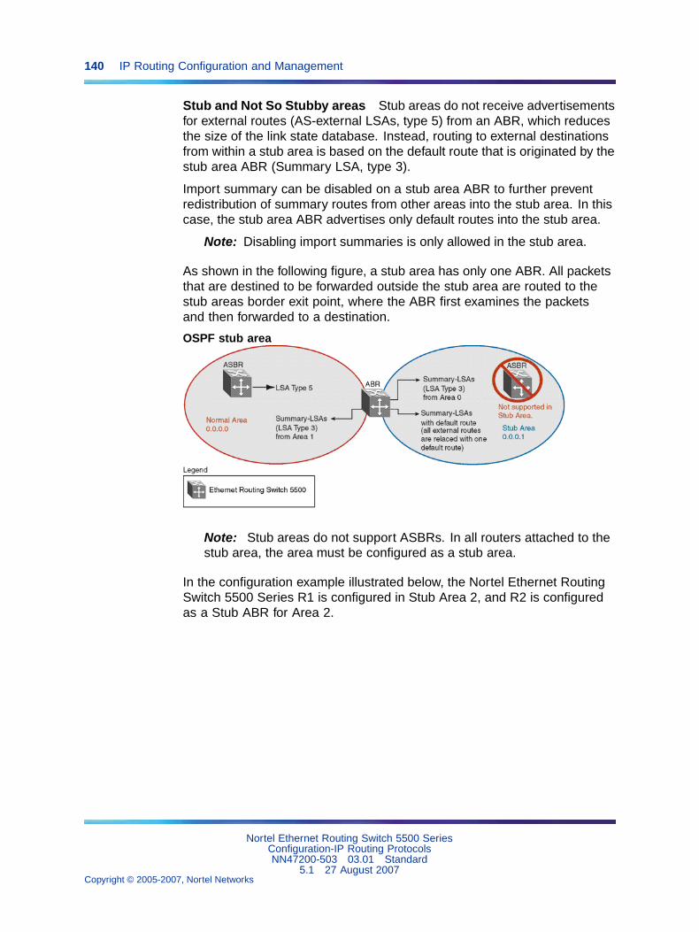
140 IP Routing Configuration and Management
Stub and Not So Stubby areas Stub areas do not receive advertisementsfor external routes (AS-external LSAs, type 5) from an ABR, which reducesthe size of the link state database. Instead, routing to external destinationsfrom within a stub area is based on the default route that is originated by thestub area ABR (Summary LSA, type 3).
Import summary can be disabled on a stub area ABR to further preventredistribution of summary routes from other areas into the stub area. In thiscase, the stub area ABR advertises only default routes into the stub area.
Note: Disabling import summaries is only allowed in the stub area.
As shown in the following figure, a stub area has only one ABR. All packetsthat are destined to be forwarded outside the stub area are routed to thestub areas border exit point, where the ABR first examines the packetsand then forwarded to a destination.
OSPF stub area
Note: Stub areas do not support ASBRs. In all routers attached to thestub area, the area must be configured as a stub area.
In the configuration example illustrated below, the Nortel Ethernet RoutingSwitch 5500 Series R1 is configured in Stub Area 2, and R2 is configuredas a Stub ABR for Area 2.
Nortel Ethernet Routing Switch 5500 SeriesConfiguration-IP Routing ProtocolsNN47200-503 03.01 Standard
5.1 27 August 2007Copyright © 2005-2007, Nortel Networks
.
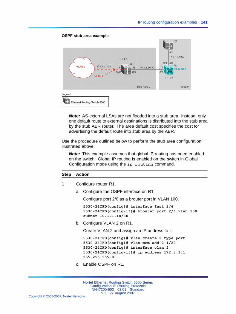
IP routing configuration examples 141
OSPF stub area example
Note: AS-external LSAs are not flooded into a stub area. Instead, onlyone default route to external destinations is distributed into the stub areaby the stub ABR router. The area default cost specifies the cost foradvertising the default route into stub area by the ABR.
Use the procedure outlined below to perform the stub area configurationillustrated above:
Note: This example assumes that global IP routing has been enabledon the switch. Global IP routing is enabled on the switch in GlobalConfiguration mode using the ip routing command.
Step Action
1 Configure router R1.
a. Configure the OSPF interface on R1.
Configure port 2/6 as a brouter port in VLAN 100.
5530-24TFD(config)# interface fast 2/65530-24TFD(config-if)# brouter port 2/6 vlan 100subnet 10.1.1.18/30
b. Configure VLAN 2 on R1.
Create VLAN 2 and assign an IP address to it.
5530-24TFD(config)# vlan create 2 type port5530-24TFD(config)# vlan mem add 2 1/205530-24TFD(config)# interface vlan 25530-24TFD(config-if)# ip address 172.3.3.1255.255.255.0
c. Enable OSPF on R1.
Nortel Ethernet Routing Switch 5500 SeriesConfiguration-IP Routing ProtocolsNN47200-503 03.01 Standard
5.1 27 August 2007Copyright © 2005-2007, Nortel Networks
.
142 IP Routing Configuration and Management
Configure R1 in stub area 2 with the Router-ID 1.1.1.5. Add theOSPF interfaces to area 2 and enable OSPF on these interfaces.
5530-24TFD(config-router)# router-id 1.1.1.55530-24TFD(config-router)# area 0.0.0.2 importnoexternal5530-24TFD(config-router)# network 10.1.1.18 area0.0.0.25530-24TFD(config-router)# network 172.3.3.1 area0.0.0.25530-24TFD(config)# router ospf enable
2 Configure router R2.
a. Configure the OSPF interface on R2.
Configure port 2/6 as a brouter port in VLAN 100.
5530-24TFD(config)# interface fast 2/65530-24TFD(config-if)# brouter port 2/6 vlan 100subnet 10.1.1.17/30
b. Configure the second OSPF interface on R2.
Configure port 2/1 as a brouter port in VLAN 300. Enable OSPFon this interface.
5530-24TFD(config)# interface fast 2/15530-24TFD(config-if)# brouter port 2/1 vlan 300subnet 10.1.1.22/305530-24TFD(config-if)# ip ospf enable
c. Enable OSPF on R2.
Configure R2 in stub area 2 with an area default cost of 10.Disable import summary to prevent R2 from sending summaryLSAs of area 0 into area 2. R2 will originate only summary LSAfor default route into area 2. Note that, by default, OSPF interface10.1.1.22 is placed into OSPF area 0.0.0.0. Because oneadditional area of 0.0.0.2 is added and OSPF interface 10.1.1.17is added to area 0.0.0.2, R2 automatically becomes a stub ABR.
5530-24TFD(config-router)# router-id 1.1.1.25530-24TFD(config-router)# area 0.0.0.2 importnoexternal5530-24TFD(config-router)# no area 0.0.0.2import-summary enable5530-24TFD(config-router)# area 0.0.0.2 default-cost105530-24TFD(config-router)# network 10.1.1.17 area0.0.0.25530-24TFD(config)# router ospf enable
—End—
Nortel Ethernet Routing Switch 5500 SeriesConfiguration-IP Routing ProtocolsNN47200-503 03.01 Standard
5.1 27 August 2007Copyright © 2005-2007, Nortel Networks
.
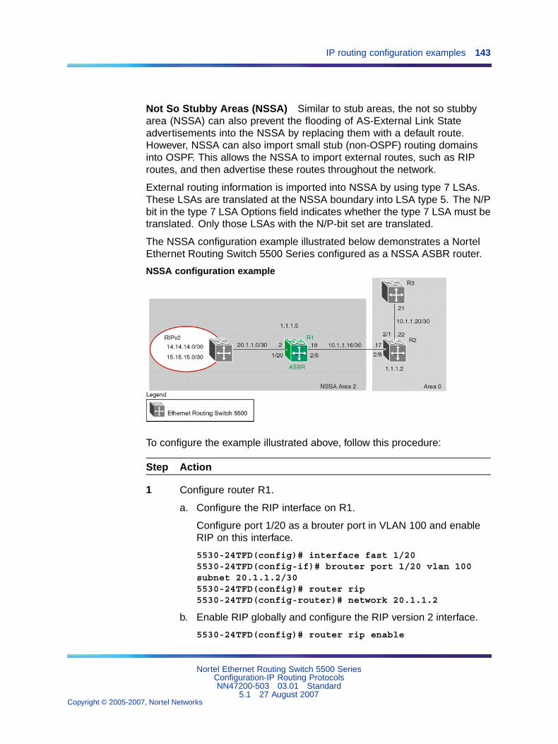
IP routing configuration examples 143
Not So Stubby Areas (NSSA) Similar to stub areas, the not so stubbyarea (NSSA) can also prevent the flooding of AS-External Link Stateadvertisements into the NSSA by replacing them with a default route.However, NSSA can also import small stub (non-OSPF) routing domainsinto OSPF. This allows the NSSA to import external routes, such as RIProutes, and then advertise these routes throughout the network.
External routing information is imported into NSSA by using type 7 LSAs.These LSAs are translated at the NSSA boundary into LSA type 5. The N/Pbit in the type 7 LSA Options field indicates whether the type 7 LSA must betranslated. Only those LSAs with the N/P-bit set are translated.
The NSSA configuration example illustrated below demonstrates a NortelEthernet Routing Switch 5500 Series configured as a NSSA ASBR router.
NSSA configuration example
To configure the example illustrated above, follow this procedure:
Step Action
1 Configure router R1.
a. Configure the RIP interface on R1.
Configure port 1/20 as a brouter port in VLAN 100 and enableRIP on this interface.
5530-24TFD(config)# interface fast 1/205530-24TFD(config-if)# brouter port 1/20 vlan 100subnet 20.1.1.2/305530-24TFD(config)# router rip5530-24TFD(config-router)# network 20.1.1.2
b. Enable RIP globally and configure the RIP version 2 interface.
5530-24TFD(config)# router rip enable
Nortel Ethernet Routing Switch 5500 SeriesConfiguration-IP Routing ProtocolsNN47200-503 03.01 Standard
5.1 27 August 2007Copyright © 2005-2007, Nortel Networks
.
144 IP Routing Configuration and Management
5530-24TFD(config)# interface vlan 1005530-24TFD(config-if)# ip rip receive version rip2send version rip2
c. Configure the OSPF interface on R1.
Configure port 2/6 as a brouter port in VLAN 200.
5530-24TFD(config)# interface fast 2/65530-24TFD(config-if)# brouter port 2/6 vlan 200subnet 10.1.1.18/30
d. Enable OSPF on R1.
Configure R1 as an ASBR, assign OSPF Router-ID 1.1.1.5,create OSPF NSSA area 2, add the OSPF interface 10.1.1.18 toarea 2, and enable OSPF on the interface.
5530-24TFD(config)# router ospf5530-24TFD(config-router)# as-boundary-router enable5530-24TFD(config-router)# router-id 1.1.1.55530-24TFD(config-router)# area 0.0.0.2 import nssa5530-24TFD(config-router)# network 10.1.1.18 area0.0.0.25530-24TFD(config)# router ospf enable
e. Configure a route policy to distribute Direct and OSPF to RIP.
Create a route policy named Rip_Dist that distributes directlyconnected and OSPF routes into RIP.
5530-24TFD(config)# route-map Rip_Dist permit 1enable match protocol direct,ospf set metric-typetype1
f. Apply the Rip_Dist route policy to RIP Out Policy.
5530-24TFD(config)# interface vlan 1005530-24TFD(config-if)# ip rip out-policy Rip_Dist
g. Configure OSPF route distribution to distribute RIP routes asAS-external LSA type 1.
5530-24TFD(config)# router ospf5530-24TFD(config-router)# redistribute rip enablemetric-type type15530-24TFD(config)# ip ospf apply redistribute rip
—End—
Nortel Ethernet Routing Switch 5500 SeriesConfiguration-IP Routing ProtocolsNN47200-503 03.01 Standard
5.1 27 August 2007Copyright © 2005-2007, Nortel Networks
.
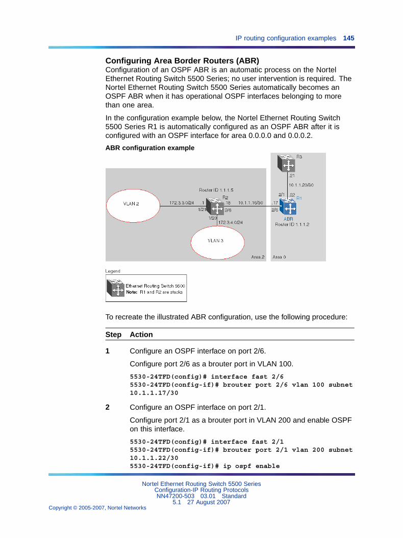
IP routing configuration examples 145
Configuring Area Border Routers (ABR)Configuration of an OSPF ABR is an automatic process on the NortelEthernet Routing Switch 5500 Series; no user intervention is required. TheNortel Ethernet Routing Switch 5500 Series automatically becomes anOSPF ABR when it has operational OSPF interfaces belonging to morethan one area.
In the configuration example below, the Nortel Ethernet Routing Switch5500 Series R1 is automatically configured as an OSPF ABR after it isconfigured with an OSPF interface for area 0.0.0.0 and 0.0.0.2.
ABR configuration example
To recreate the illustrated ABR configuration, use the following procedure:
Step Action
1 Configure an OSPF interface on port 2/6.
Configure port 2/6 as a brouter port in VLAN 100.
5530-24TFD(config)# interface fast 2/65530-24TFD(config-if)# brouter port 2/6 vlan 100 subnet10.1.1.17/30
2 Configure an OSPF interface on port 2/1.
Configure port 2/1 as a brouter port in VLAN 200 and enable OSPFon this interface.
5530-24TFD(config)# interface fast 2/15530-24TFD(config-if)# brouter port 2/1 vlan 200 subnet10.1.1.22/305530-24TFD(config-if)# ip ospf enable
Nortel Ethernet Routing Switch 5500 SeriesConfiguration-IP Routing ProtocolsNN47200-503 03.01 Standard
5.1 27 August 2007Copyright © 2005-2007, Nortel Networks
.
146 IP Routing Configuration and Management
3 Enable OSPF.
Configure R1 as an ABR. Note that, by default, OSPF interface10.1.1.22 is placed into OSPF area 0.0.0.0. Because one additionalarea of 0.0.0.2 is created and OSPF interface 10.1.1.17 is added toarea 0.0.0.2, R1 automatically becomes an ABR.
5530-24TFD(config-router)# router-id 1.1.1.25530-24TFD(config-router)# area 0.0.0.25530-24TFD(config-router)# network 10.1.1.17area 0.0.0.25530-24TFD(config)# router ospf enable
4 Configure area range.
Configure R1 to enclose the two networks (172.3.3.0 and 172.3.4.0)into an address range entry 172.3.0.0 in area 0.0.0.2. R1 willgenerate a single summary advertisement into the backbone for172.3.0.0 with metric 100.
5530-24TFD(config-router)# area 0.0.0.2 range172.3.0.0/16 summary-link advertise-mode summarizeadvertise-metric 100
—End—
To display the created areas, use the show ip ospf area command.Usage of this command on the example configuration would yield thefollowing output:
Area ID: 0.0.0.0Import Summaries: YesImport Type: ExternalIntra-Area SPF Runs: 2Reachable Area Border Routers: 0Reachable Autonomous System Border Routers: 0Link-State Advertisements: 0Link-State Advertisements Checksum: 0(0x0)Area ID: 0.0.0.2Import Summaries: YesImport Type: ExternalIntra-Area SPF Runs: 2Reachable Area Border Routers: 1Reachable Autonomous System Border Routers: 0Link-State Advertisements: 0Link-State Advertisements Checksum: 0(0x0)
To display area ranges, use the show ip ospf area-range command.Usage of this command on the example configuration would yield thefollowing output:
Nortel Ethernet Routing Switch 5500 SeriesConfiguration-IP Routing ProtocolsNN47200-503 03.01 Standard
5.1 27 August 2007Copyright © 2005-2007, Nortel Networks
.
IP routing configuration examples 147
Area ID Range Subnet/Mask Range Type Advertise Mode Metric----------- ------------------ ------------- -------------- ------0.0.0.2 172.3.0.0/16 Summary Link Summarize 100
To display ABR status, use the show ip ospf command. Usage of thiscommand on the example configuration would yield the following output:
Router ID: 1.1.1.2Admin Status: EnabledVersion Number: 2Area Border Router Oper Status: TrueAS Boundary Router Config Status: FalseExternal Link-State Advertisements: 2External Link-State Checksum: 45698(0xb282)Type-of-Service (TOS) Routing Supported: FalseOriginated Link-State Advertisements: 5New Link-State Advertisements Received: 34OSPF Traps: DisabledAuto Virtual Link Creation: DisabledSPF Hold-Down Time: 10RFC 1583 Compatibility: Enabled
Configuring Autonomous System Border Routers (ASBR)An ASBR is a router that has a connection to another Autonomous Systemto distribute any external routes that originated from a protocol into OSPF. ANortel Ethernet Routing Switch 5500 Series configured as an ASBR can:
• Distribute all OSPF routes to RIP.
• Distribute RIP, direct, or static routes to OSPF.
Distributing OSPF routes to RIP and RIP to OSPF using AS-externalLSA Type 1 metrics The configuration example illustrated below, displaysa Nortel Ethernet Routing Switch 5500 Series configured as an ASBRbetween an OSPF and RIP version 2 network. In this example, the routerdistributes all OSPF routes to the RIP network and all RIP routes to theOSPF network.
Nortel Ethernet Routing Switch 5500 SeriesConfiguration-IP Routing ProtocolsNN47200-503 03.01 Standard
5.1 27 August 2007Copyright © 2005-2007, Nortel Networks
.
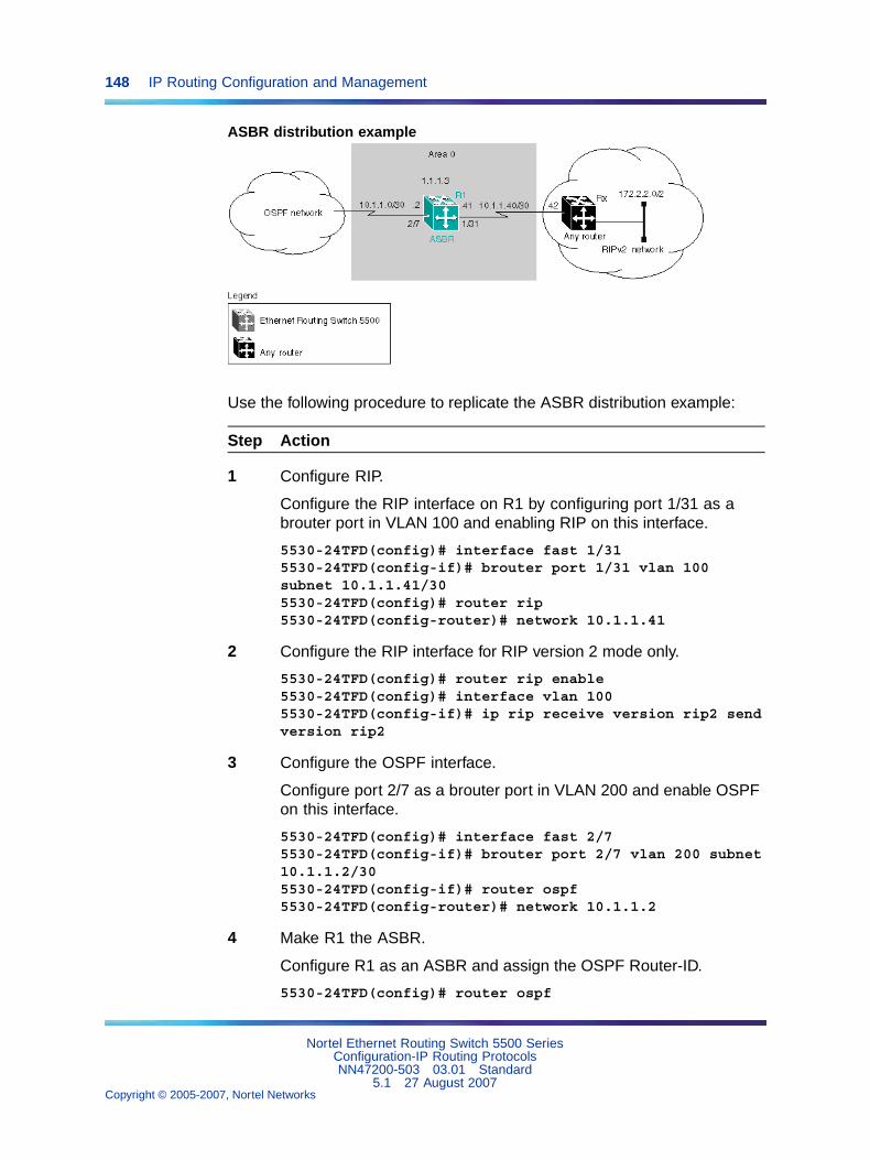
148 IP Routing Configuration and Management
ASBR distribution example
Use the following procedure to replicate the ASBR distribution example:
Step Action
1 Configure RIP.
Configure the RIP interface on R1 by configuring port 1/31 as abrouter port in VLAN 100 and enabling RIP on this interface.
5530-24TFD(config)# interface fast 1/315530-24TFD(config-if)# brouter port 1/31 vlan 100subnet 10.1.1.41/305530-24TFD(config)# router rip5530-24TFD(config-router)# network 10.1.1.41
2 Configure the RIP interface for RIP version 2 mode only.
5530-24TFD(config)# router rip enable5530-24TFD(config)# interface vlan 1005530-24TFD(config-if)# ip rip receive version rip2 sendversion rip2
3 Configure the OSPF interface.
Configure port 2/7 as a brouter port in VLAN 200 and enable OSPFon this interface.
5530-24TFD(config)# interface fast 2/75530-24TFD(config-if)# brouter port 2/7 vlan 200 subnet10.1.1.2/305530-24TFD(config-if)# router ospf5530-24TFD(config-router)# network 10.1.1.2
4 Make R1 the ASBR.
Configure R1 as an ASBR and assign the OSPF Router-ID.
5530-24TFD(config)# router ospf
Nortel Ethernet Routing Switch 5500 SeriesConfiguration-IP Routing ProtocolsNN47200-503 03.01 Standard
5.1 27 August 2007Copyright © 2005-2007, Nortel Networks
.
IP routing configuration examples 149
5530-24TFD(config-router)# as-boundary-router enable5530-24TFD(config-router)# router-id 1.1.1.35530-24TFD(config)# router ospf enable
5 Configure OSPF route distribution.
Configure OSPF route distribution to import RIP into OSPF. TheNortel Ethernet Routing Switch 5500 Series distributes the RIProutes as AS-external LSA (LSA type 5), using external metric type 1.
5530-24TFD(config)# router ospf5530-24TFD(config-router)# redistribute rip enablemetric 10 metric-type type15530-24TFD(config)# ip ospf apply redistribute rip
6 Configure a route policy.
A route policy is required for OSPF to RIP route redistribution. Afterthe route policy is created, apply it to the RIP interface. The followingcommand creates a route policy named allow which distributes bothdirect and OSPF interfaces.
5530-24TFD(config)# route-map allow permit 1 enablematch protocol direct,ospf
7 Apply the route policy to the RIP Out Policy.
The following commands apply the route policy created in step 6 toRIP interface 10.1.1.41.
5530-24TFD(config)# interface vlan 1005530-24TFD(config-if)# ip rip out-policy allow
—End—
The configuration steps described in the above example distributes all OSPFroutes to RIP. However, there are times when it can be more advantageousto distribute only a default route to RIP. The following configuration stepsdescribe how to distribute only a default route to RIP instead of all OSPFroutes to RIP.
To configure R1 to distribute a default route only to RIP, complete thefollowing steps:
Step Action
1 Configure an IP prefix list with a default route.
The following command creates an IP prefix list named default withan IP address of 0.0.0.0.
5530-24TFD(config)# ip prefix-list default 0.0.0.0/0
Nortel Ethernet Routing Switch 5500 SeriesConfiguration-IP Routing ProtocolsNN47200-503 03.01 Standard
5.1 27 August 2007Copyright © 2005-2007, Nortel Networks
.
150 IP Routing Configuration and Management
2 Configure a route policy.
Create a route policy named Policy_Default which distributesthe IP prefix list created in step 1. Note that ospf is selected asthe match-protocol value. This causes the default route to beadvertised through RIP only if OSPF is operational.
5530-24TFD(config)# route-map Policy_Default permit 1enable match protocol ospf set injectlist default5530-24TFD(config)# route-map Policy_Default1 set metric-type type1
3 Apply the route policy to the RIP Out Policy.
Apply the route policy created in step 2 to RIP interface 10.1.1.41.
5530-24TFD(config)# interface vlan 1005530-24TFD(config-if)# ip rip out-policy Policy_Default
—End—
Controlling NSSA external route advertisementsIn an OSPF NSSA, the NSSA N/p-bit (in the OSPF hello packets Optionsfield) is used to tell the ABR which external routes can be advertised to otherareas. When the NSSA N/p-bit is set true, the ABR exports the externalroute. This is the default setting for the Nortel Ethernet Routing Switch 5500Series. When the NSSA N/p-bit is not set true, the ABR drops the externalroute. A route policy can be created on the Nortel Ethernet Routing Switch5500 Series to manipulate the N/ p-bit value.
For example, the illustration below shows a RIP network located in NSSA2. If advertising the 15.15.15.0/24 network to area 0 is the only desiredaction, perform the following tasks:
• Enable R1 as an OSPF ASBR.
• Create NSSA area 0.0.0.2.
• Create a route policy to advertise OSPF and direct interfaces to RIP.
• Create a route policy to only advertise RIP network 15.15.15.0/24 toarea 0 by using the NSSA N/p-bit.
Nortel Ethernet Routing Switch 5500 SeriesConfiguration-IP Routing ProtocolsNN47200-503 03.01 Standard
5.1 27 August 2007Copyright © 2005-2007, Nortel Networks
.
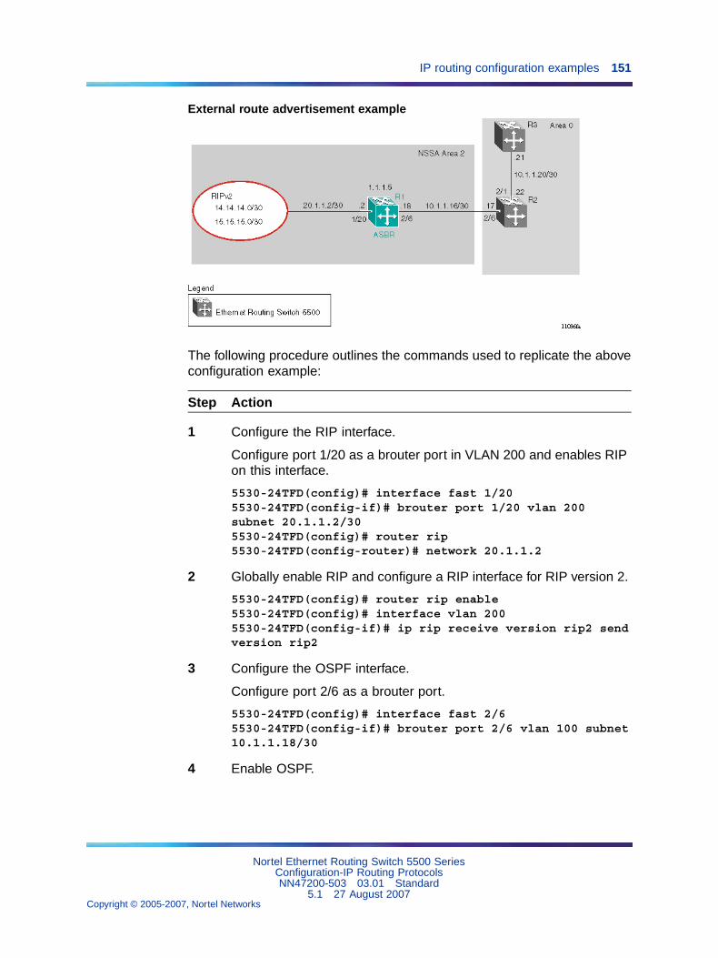
IP routing configuration examples 151
External route advertisement example
The following procedure outlines the commands used to replicate the aboveconfiguration example:
Step Action
1 Configure the RIP interface.
Configure port 1/20 as a brouter port in VLAN 200 and enables RIPon this interface.
5530-24TFD(config)# interface fast 1/205530-24TFD(config-if)# brouter port 1/20 vlan 200subnet 20.1.1.2/305530-24TFD(config)# router rip5530-24TFD(config-router)# network 20.1.1.2
2 Globally enable RIP and configure a RIP interface for RIP version 2.
5530-24TFD(config)# router rip enable5530-24TFD(config)# interface vlan 2005530-24TFD(config-if)# ip rip receive version rip2 sendversion rip2
3 Configure the OSPF interface.
Configure port 2/6 as a brouter port.
5530-24TFD(config)# interface fast 2/65530-24TFD(config-if)# brouter port 2/6 vlan 100 subnet10.1.1.18/30
4 Enable OSPF.
Nortel Ethernet Routing Switch 5500 SeriesConfiguration-IP Routing ProtocolsNN47200-503 03.01 Standard
5.1 27 August 2007Copyright © 2005-2007, Nortel Networks
.
152 IP Routing Configuration and Management
Configure R1 as an ASBR, assign the OSPF Router-ID 1.1.1.5,create OSPF NSSA area 2, add the OSPF interface 10.1.1.18 toarea 2, and enable OSPF on the interface. Enable ASBR and OSPFglobally.
5530-24TFD(config)# router ospf5530-24TFD(config-router)# router-id 1.1.1.55530-24TFD(config-router)# as-boundary-router enable5530-24TFD(config-router)# area 0.0.0.2 import nssa5530-24TFD(config-router)# network 10.1.1.18 area0.0.0.25530-24TFD(config)# router ospf enable
5 Create a route policy named Rip_Dist that distributes directlyconnected and OSPF routes into RIP.
5530-24TFD(config)# route-map Rip_Dist permit 1 enablematch protocol direct,ospf set metric-type type1
6 Apply route policy to RIP Out Policy.
5530-24TFD(config)# interface vlan 2005530-24TFD(config-if)# ip rip out-policy Rip_Dist
7 Add two prefix lists (15net and 14net) that are associated with thenetwork addresses from the RIP version 2 network.
5530-24TFD(config)# ip prefix-list 15net 15.15.15.0/245530-24TFD(config)# ip prefix-list 14net 14.14.14.0/24
8 Create a route policy named P_bit that sets the NSSA N/P-bit onlyfor the prefix list named 15net.
5530-24TFD(config)# route-map P_bit permit 1 enablematch network 15net set nssa-pbit enable5530-24TFD(config)# route-map P_bit permit 2 enablematch network 14net5530-24TFD(config)# no route-map P_bit 2 set nssa-pbitenable
9 Configure OSPF route distribution to distribute RIP routes asAS-external LSA Type 1.
5530-24TFD(config)# router ospf5530-24TFD(config-router)# redistribute rip enablemetric-type type1 route-policy P_bit5530-24TFD(config)# ip ospf apply redistribute rip
—End—
Nortel Ethernet Routing Switch 5500 SeriesConfiguration-IP Routing ProtocolsNN47200-503 03.01 Standard
5.1 27 August 2007Copyright © 2005-2007, Nortel Networks
.
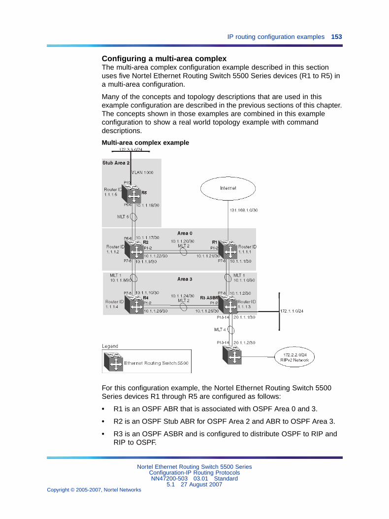
IP routing configuration examples 153
Configuring a multi-area complexThe multi-area complex configuration example described in this sectionuses five Nortel Ethernet Routing Switch 5500 Series devices (R1 to R5) ina multi-area configuration.
Many of the concepts and topology descriptions that are used in thisexample configuration are described in the previous sections of this chapter.The concepts shown in those examples are combined in this exampleconfiguration to show a real world topology example with commanddescriptions.
Multi-area complex example
For this configuration example, the Nortel Ethernet Routing Switch 5500Series devices R1 through R5 are configured as follows:
• R1 is an OSPF ABR that is associated with OSPF Area 0 and 3.
• R2 is an OSPF Stub ABR for OSPF Area 2 and ABR to OSPF Area 3.
• R3 is an OSPF ASBR and is configured to distribute OSPF to RIP andRIP to OSPF.
Nortel Ethernet Routing Switch 5500 SeriesConfiguration-IP Routing ProtocolsNN47200-503 03.01 Standard
5.1 27 August 2007Copyright © 2005-2007, Nortel Networks
.
154 IP Routing Configuration and Management
• R4 is an OSPF internal router in Area 3.
• R5 is an internal OSPF stub router in Area 2.
• All interfaces used for this configuration are ethernet, therefore theOSPF interfaces are broadcast.
• The interface priority value on R5 is set to 0, therefore R5 cannotbecome a designated router (DR).
• Configure the OSPF Router Priority so that R1 becomes the DR (priorityof 100) and R2 becomes backup designated router (BDR) with a priorityvalue of 50.
Stub and NSSA areas are used to reduce the LSDB size by excludingexternal LSAs. The stub ABR advertises a default route into the stub areafor all external routes.
The following list outlines the commands used to create the illustratedconfiguration. A similar listing could be provided by using the showrunning-config command.
1. R1 configuration commands
! *** STP (Phase 1) *** !spanning-tree stp 2 createspanning-tree stp 3 createspanning-tree cost-calc-mode dot1dspanning-tree port-mode normalspanning-tree stp 1 priority 8000spanning-tree stp 1 hello-time 2spanning-tree stp 1 max-age 20spanning-tree stp 1 forward-time 15spanning-tree stp 1 tagged-bpdu disabletagged-bpdu-vid 4001spanning-tree stp 1 multicast-address 01:80:c2:00:00:00spanning-tree stp 2 priority 8000spanning-tree stp 2 hello-time 2spanning-tree stp 2 max-age 20spanning-tree stp 2 forward-time 15spanning-tree stp 2 tagged-bpdu enabletagged-bpdu-vid 4002spanning-tree stp 2 multicast-address 01:80:c2:00:00:00spanning-tree stp 3 priority 8000spanning-tree stp 3 hello-time 2spanning-tree stp 3 max-age 20spanning-tree stp 3 forward-time 15spanning-tree stp 3 tagged-bpdu enabletagged-bpdu-vid 4003spanning-tree stp 3 multicast-address 01:80:c2:00:00:00! *** VLAN *** !vlan configcontrol autopvidauto-pvid
Nortel Ethernet Routing Switch 5500 SeriesConfiguration-IP Routing ProtocolsNN47200-503 03.01 Standard
5.1 27 August 2007Copyright © 2005-2007, Nortel Networks
.
IP routing configuration examples 155
vlan name 1 "VLAN #1"vlan create 102 name "VLAN #102" type portvlan create 103 name "VLAN #103" type portvlan ports 1-24 tagging unTagAll filter-untagged-framedisable filter-unregistered-frames enable priority 0vlan ports 25-26 tagging tagAll filter-untagged-framedisable filter-unregistered-frames enable priority 0vlan members 1 24-26vlan members 102 1-2vlan members 103 7-8vlan ports 1-2 pvid 102vlan ports 3-6 pvid 1vlan ports 7-8 pvid 103vlan ports 9-26 pvid 1vlan igmp unknown-mcast-no-flood disablevlan igmp 1 snooping disablevlan igmp 1 proxy disable robust-value 2query-interval 125vlan igmp 102 snooping disablevlan igmp 102 proxy disable robust-value 2query-interval 125vlan igmp 103 snooping disablevlan igmp 103 proxy disable robust-value 2query-interval 125vlan mgmt 1! *** MLT (Phase 1) *** !no mltmlt 1 name "Trunk #1" enable member 7-8 learning normalmlt 1 learning normalmlt 1 bpdu all-portsmlt 1 loadbalance basicmlt 2 name "Trunk #2" enable member 1-2 learning normalmlt 2 learning normalmlt 2 bpdu all-portsmlt 2 loadbalance basic! *** STP (Phase 2) *** !spanning-tree stp 1 add-vlan 1spanning-tree stp 2 add-vlan 102spanning-tree stp 3 add-vlan 103spanning-tree stp 2 enablespanning-tree stp 3 enableinterface FastEthernet ALLspanning-tree port 24-26 learning normalspanning-tree port 1-2 stp 2 learning normalspanning-tree port 7-8 stp 3 learning normalspanning-tree port 24-26 cost 1 priority 80spanning-tree port 1-2 stp 2 cost 1 priority 80spanning-tree port 7-8 stp 3 cost 1 priority 80spanning-tree bpdu-filtering port 1-26 timeout 120no spanning-tree bpdu-filtering port 1-26
Nortel Ethernet Routing Switch 5500 SeriesConfiguration-IP Routing ProtocolsNN47200-503 03.01 Standard
5.1 27 August 2007Copyright © 2005-2007, Nortel Networks
.
156 IP Routing Configuration and Management
enableexit! *** MLT (Phase 2) *** !mlt spanning-tree 1 stp 3 learning normalmlt spanning-tree 2 stp 2 learning normal! *** L3 *** !no ip directed-broadcast enableip routinginterface vlan 102ip address 10.1.1.21 255.255.255.252 2ip dhcp-relay min-sec 0 mode bootp_dhcpno ip dhcp-relay broadcastip dhcp-relayexitinterface vlan 103ip address 10.1.1.1 255.255.255.252 3ip dhcp-relay min-sec 0 mode bootp_dhcpno ip dhcp-relay broadcastip dhcp-relayexitip arp timeout 360ip dhcp-relayip blocking-mode none! *** OSPF *** !router ospf enablerouter ospfrouter-id 1.1.1.1no as-boundary-router enableno trap enabletimers basic holddown 10rfc1583-compatibility enabledefault-cost ethernet 100default-cost fast-ethernet 10default-cost gig-ethernet 1default-cost ten-gig-ethernet 1area 0.0.0.3 import externalarea 0.0.0.3 import-summaries enableexitenableconfigure terminalinterface vlan 103ip ospf area 0.0.0.3ip ospf network broadcastip ospf priority 100ip ospf authentication-type noneip ospf mtu-ignore enableno ip ospf advertise-when-down enableip ospf transmit-delay 1ip ospf retransmit-interval 5ip ospf hello-interval 10
Nortel Ethernet Routing Switch 5500 SeriesConfiguration-IP Routing ProtocolsNN47200-503 03.01 Standard
5.1 27 August 2007Copyright © 2005-2007, Nortel Networks
.
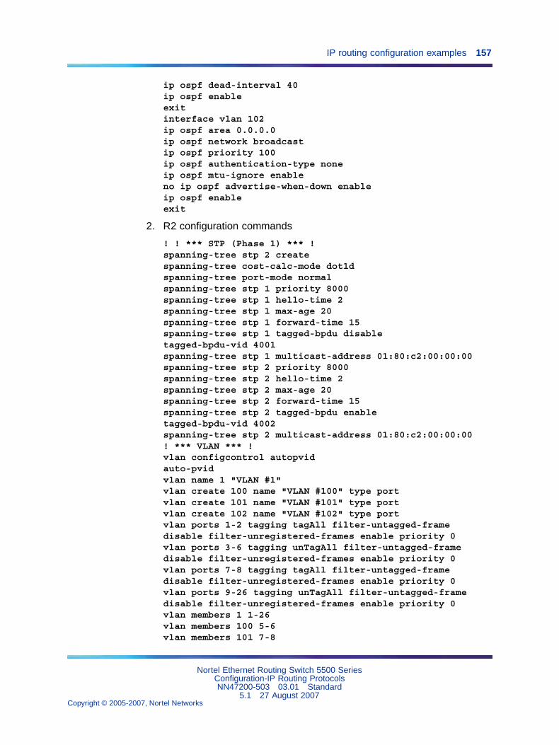
IP routing configuration examples 157
ip ospf dead-interval 40ip ospf enableexitinterface vlan 102ip ospf area 0.0.0.0ip ospf network broadcastip ospf priority 100ip ospf authentication-type noneip ospf mtu-ignore enableno ip ospf advertise-when-down enableip ospf enableexit
2. R2 configuration commands
! ! *** STP (Phase 1) *** !spanning-tree stp 2 createspanning-tree cost-calc-mode dot1dspanning-tree port-mode normalspanning-tree stp 1 priority 8000spanning-tree stp 1 hello-time 2spanning-tree stp 1 max-age 20spanning-tree stp 1 forward-time 15spanning-tree stp 1 tagged-bpdu disabletagged-bpdu-vid 4001spanning-tree stp 1 multicast-address 01:80:c2:00:00:00spanning-tree stp 2 priority 8000spanning-tree stp 2 hello-time 2spanning-tree stp 2 max-age 20spanning-tree stp 2 forward-time 15spanning-tree stp 2 tagged-bpdu enabletagged-bpdu-vid 4002spanning-tree stp 2 multicast-address 01:80:c2:00:00:00! *** VLAN *** !vlan configcontrol autopvidauto-pvidvlan name 1 "VLAN #1"vlan create 100 name "VLAN #100" type portvlan create 101 name "VLAN #101" type portvlan create 102 name "VLAN #102" type portvlan ports 1-2 tagging tagAll filter-untagged-framedisable filter-unregistered-frames enable priority 0vlan ports 3-6 tagging unTagAll filter-untagged-framedisable filter-unregistered-frames enable priority 0vlan ports 7-8 tagging tagAll filter-untagged-framedisable filter-unregistered-frames enable priority 0vlan ports 9-26 tagging unTagAll filter-untagged-framedisable filter-unregistered-frames enable priority 0vlan members 1 1-26vlan members 100 5-6vlan members 101 7-8
Nortel Ethernet Routing Switch 5500 SeriesConfiguration-IP Routing ProtocolsNN47200-503 03.01 Standard
5.1 27 August 2007Copyright © 2005-2007, Nortel Networks
.
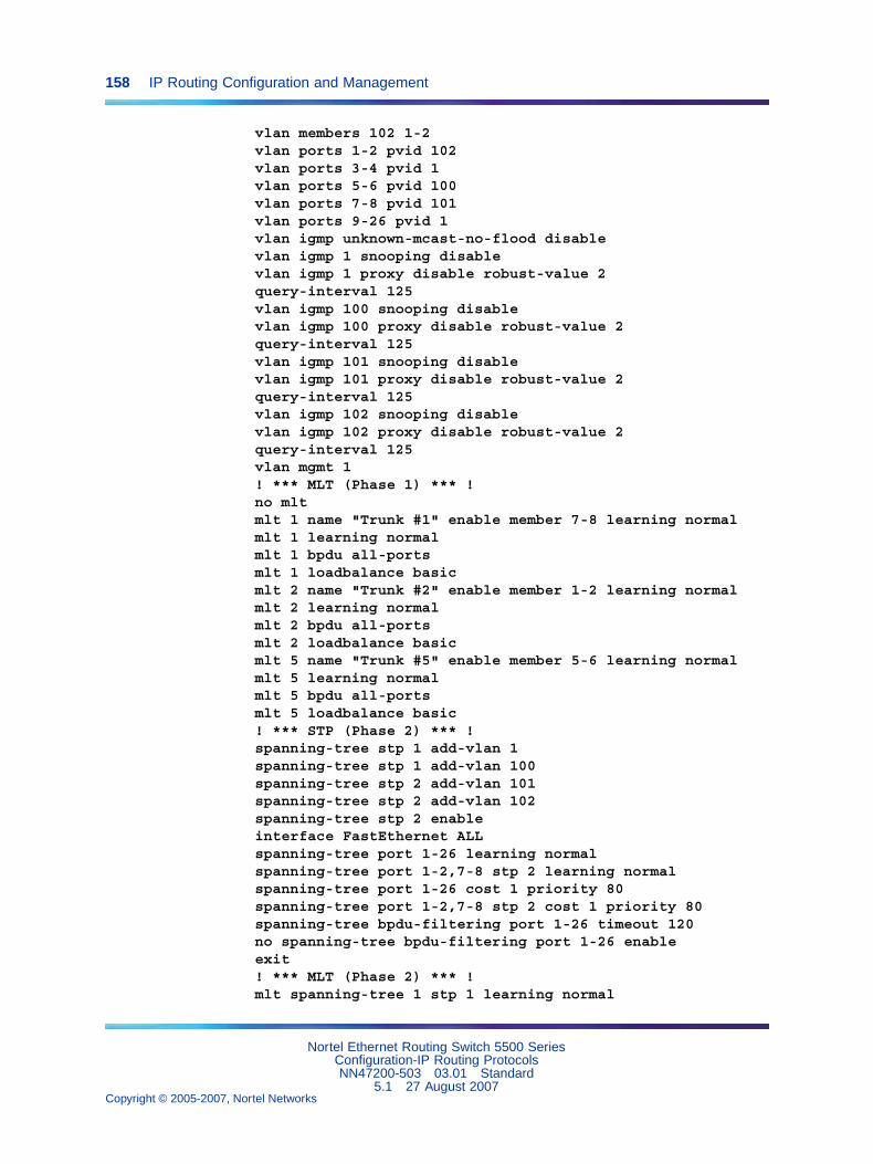
158 IP Routing Configuration and Management
vlan members 102 1-2vlan ports 1-2 pvid 102vlan ports 3-4 pvid 1vlan ports 5-6 pvid 100vlan ports 7-8 pvid 101vlan ports 9-26 pvid 1vlan igmp unknown-mcast-no-flood disablevlan igmp 1 snooping disablevlan igmp 1 proxy disable robust-value 2query-interval 125vlan igmp 100 snooping disablevlan igmp 100 proxy disable robust-value 2query-interval 125vlan igmp 101 snooping disablevlan igmp 101 proxy disable robust-value 2query-interval 125vlan igmp 102 snooping disablevlan igmp 102 proxy disable robust-value 2query-interval 125vlan mgmt 1! *** MLT (Phase 1) *** !no mltmlt 1 name "Trunk #1" enable member 7-8 learning normalmlt 1 learning normalmlt 1 bpdu all-portsmlt 1 loadbalance basicmlt 2 name "Trunk #2" enable member 1-2 learning normalmlt 2 learning normalmlt 2 bpdu all-portsmlt 2 loadbalance basicmlt 5 name "Trunk #5" enable member 5-6 learning normalmlt 5 learning normalmlt 5 bpdu all-portsmlt 5 loadbalance basic! *** STP (Phase 2) *** !spanning-tree stp 1 add-vlan 1spanning-tree stp 1 add-vlan 100spanning-tree stp 2 add-vlan 101spanning-tree stp 2 add-vlan 102spanning-tree stp 2 enableinterface FastEthernet ALLspanning-tree port 1-26 learning normalspanning-tree port 1-2,7-8 stp 2 learning normalspanning-tree port 1-26 cost 1 priority 80spanning-tree port 1-2,7-8 stp 2 cost 1 priority 80spanning-tree bpdu-filtering port 1-26 timeout 120no spanning-tree bpdu-filtering port 1-26 enableexit! *** MLT (Phase 2) *** !mlt spanning-tree 1 stp 1 learning normal
Nortel Ethernet Routing Switch 5500 SeriesConfiguration-IP Routing ProtocolsNN47200-503 03.01 Standard
5.1 27 August 2007Copyright © 2005-2007, Nortel Networks
.
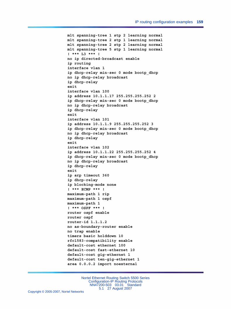
IP routing configuration examples 159
mlt spanning-tree 1 stp 2 learning normalmlt spanning-tree 2 stp 1 learning normalmlt spanning-tree 2 stp 2 learning normalmlt spanning-tree 5 stp 1 learning normal! *** L3 *** !no ip directed-broadcast enableip routinginterface vlan 1ip dhcp-relay min-sec 0 mode bootp_dhcpno ip dhcp-relay broadcastip dhcp-relayexitinterface vlan 100ip address 10.1.1.17 255.255.255.252 2ip dhcp-relay min-sec 0 mode bootp_dhcpno ip dhcp-relay broadcastip dhcp-relayexitinterface vlan 101ip address 10.1.1.9 255.255.255.252 3ip dhcp-relay min-sec 0 mode bootp_dhcpno ip dhcp-relay broadcastip dhcp-relayexitinterface vlan 102ip address 10.1.1.22 255.255.255.252 4ip dhcp-relay min-sec 0 mode bootp_dhcpno ip dhcp-relay broadcastip dhcp-relayexitip arp timeout 360ip dhcp-relayip blocking-mode none! *** ECMP *** !maximum-path 1 ripmaximum-path 1 ospfmaximum-path 1! *** OSPF *** !router ospf enablerouter ospfrouter-id 1.1.1.2no as-boundary-router enableno trap enabletimers basic holddown 10rfc1583-compatibility enabledefault-cost ethernet 100default-cost fast-ethernet 10default-cost gig-ethernet 1default-cost ten-gig-ethernet 1area 0.0.0.2 import noexternal
Nortel Ethernet Routing Switch 5500 SeriesConfiguration-IP Routing ProtocolsNN47200-503 03.01 Standard
5.1 27 August 2007Copyright © 2005-2007, Nortel Networks
.
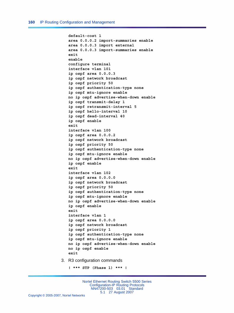
160 IP Routing Configuration and Management
default-cost 1area 0.0.0.2 import-summaries enablearea 0.0.0.3 import externalarea 0.0.0.3 import-summaries enableexitenableconfigure terminalinterface vlan 101ip ospf area 0.0.0.3ip ospf network broadcastip ospf priority 50ip ospf authentication-type noneip ospf mtu-ignore enableno ip ospf advertise-when-down enableip ospf transmit-delay 1ip ospf retransmit-interval 5ip ospf hello-interval 10ip ospf dead-interval 40ip ospf enableexitinterface vlan 100ip ospf area 0.0.0.2ip ospf network broadcastip ospf priority 50ip ospf authentication-type noneip ospf mtu-ignore enableno ip ospf advertise-when-down enableip ospf enableexitinterface vlan 102ip ospf area 0.0.0.0ip ospf network broadcastip ospf priority 50ip ospf authentication-type noneip ospf mtu-ignore enableno ip ospf advertise-when-down enableip ospf enableexitinterface vlan 1ip ospf area 0.0.0.0ip ospf network broadcastip ospf priority 1ip ospf authentication-type noneip ospf mtu-ignore enableno ip ospf advertise-when-down enableno ip ospf enableexit
3. R3 configuration commands
! *** STP (Phase 1) *** !
Nortel Ethernet Routing Switch 5500 SeriesConfiguration-IP Routing ProtocolsNN47200-503 03.01 Standard
5.1 27 August 2007Copyright © 2005-2007, Nortel Networks
.
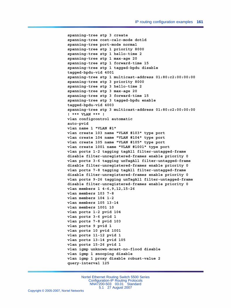
IP routing configuration examples 161
spanning-tree stp 3 createspanning-tree cost-calc-mode dot1dspanning-tree port-mode normalspanning-tree stp 1 priority 8000spanning-tree stp 1 hello-time 2spanning-tree stp 1 max-age 20spanning-tree stp 1 forward-time 15spanning-tree stp 1 tagged-bpdu disabletagged-bpdu-vid 4001spanning-tree stp 1 multicast-address 01:80:c2:00:00:00spanning-tree stp 3 priority 8000spanning-tree stp 3 hello-time 2spanning-tree stp 3 max-age 20spanning-tree stp 3 forward-time 15spanning-tree stp 3 tagged-bpdu enabletagged-bpdu-vid 4003spanning-tree stp 3 multicast-address 01:80:c2:00:00:00! *** VLAN *** !vlan configcontrol automaticauto-pvidvlan name 1 "VLAN #1"vlan create 103 name "VLAN #103" type portvlan create 104 name "VLAN #104" type portvlan create 105 name "VLAN #105" type portvlan create 1001 name "VLAN #1001" type portvlan ports 1-2 tagging tagAll filter-untagged-framedisable filter-unregistered-frames enable priority 0vlan ports 3-6 tagging unTagAll filter-untagged-framedisable filter-unregistered-frames enable priority 0vlan ports 7-8 tagging tagAll filter-untagged-framedisable filter-unregistered-frames enable priority 0vlan ports 9-26 tagging unTagAll filter-untagged-framedisable filter-unregistered-frames enable priority 0vlan members 1 4-6,9,12,15-26vlan members 103 7-8vlan members 104 1-2vlan members 105 13-14vlan members 1001 10vlan ports 1-2 pvid 104vlan ports 3-6 pvid 1vlan ports 7-8 pvid 103vlan ports 9 pvid 1vlan ports 10 pvid 1001vlan ports 11-12 pvid 1vlan ports 13-14 pvid 105vlan ports 15-26 pvid 1vlan igmp unknown-mcast-no-flood disablevlan igmp 1 snooping disablevlan igmp 1 proxy disable robust-value 2query-interval 125
Nortel Ethernet Routing Switch 5500 SeriesConfiguration-IP Routing ProtocolsNN47200-503 03.01 Standard
5.1 27 August 2007Copyright © 2005-2007, Nortel Networks
.
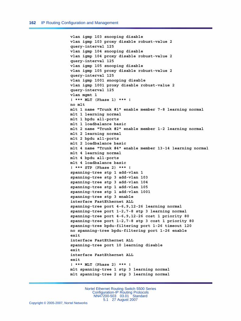
162 IP Routing Configuration and Management
vlan igmp 103 snooping disablevlan igmp 103 proxy disable robust-value 2query-interval 125vlan igmp 104 snooping disablevlan igmp 104 proxy disable robust-value 2query-interval 125vlan igmp 105 snooping disablevlan igmp 105 proxy disable robust-value 2query-interval 125vlan igmp 1001 snooping disablevlan igmp 1001 proxy disable robust-value 2query-interval 125vlan mgmt 1! *** MLT (Phase 1) *** !no mltmlt 1 name "Trunk #1" enable member 7-8 learning normalmlt 1 learning normalmlt 1 bpdu all-portsmlt 1 loadbalance basicmlt 2 name "Trunk #2" enable member 1-2 learning normalmlt 2 learning normalmlt 2 bpdu all-portsmlt 2 loadbalance basicmlt 4 name "Trunk #4" enable member 13-14 learning normalmlt 4 learning normalmlt 4 bpdu all-portsmlt 4 loadbalance basic! *** STP (Phase 2) *** !spanning-tree stp 1 add-vlan 1spanning-tree stp 3 add-vlan 103spanning-tree stp 3 add-vlan 104spanning-tree stp 1 add-vlan 105spanning-tree stp 1 add-vlan 1001spanning-tree stp 3 enableinterface FastEthernet ALLspanning-tree port 4-6,9,12-26 learning normalspanning-tree port 1-2,7-8 stp 3 learning normalspanning-tree port 4-6,9,12-26 cost 1 priority 80spanning-tree port 1-2,7-8 stp 3 cost 1 priority 80spanning-tree bpdu-filtering port 1-26 timeout 120no spanning-tree bpdu-filtering port 1-26 enableexitinterface FastEthernet ALLspanning-tree port 10 learning disableexitinterface FastEthernet ALLexit! *** MLT (Phase 2) *** !mlt spanning-tree 1 stp 3 learning normalmlt spanning-tree 2 stp 3 learning normal
Nortel Ethernet Routing Switch 5500 SeriesConfiguration-IP Routing ProtocolsNN47200-503 03.01 Standard
5.1 27 August 2007Copyright © 2005-2007, Nortel Networks
.
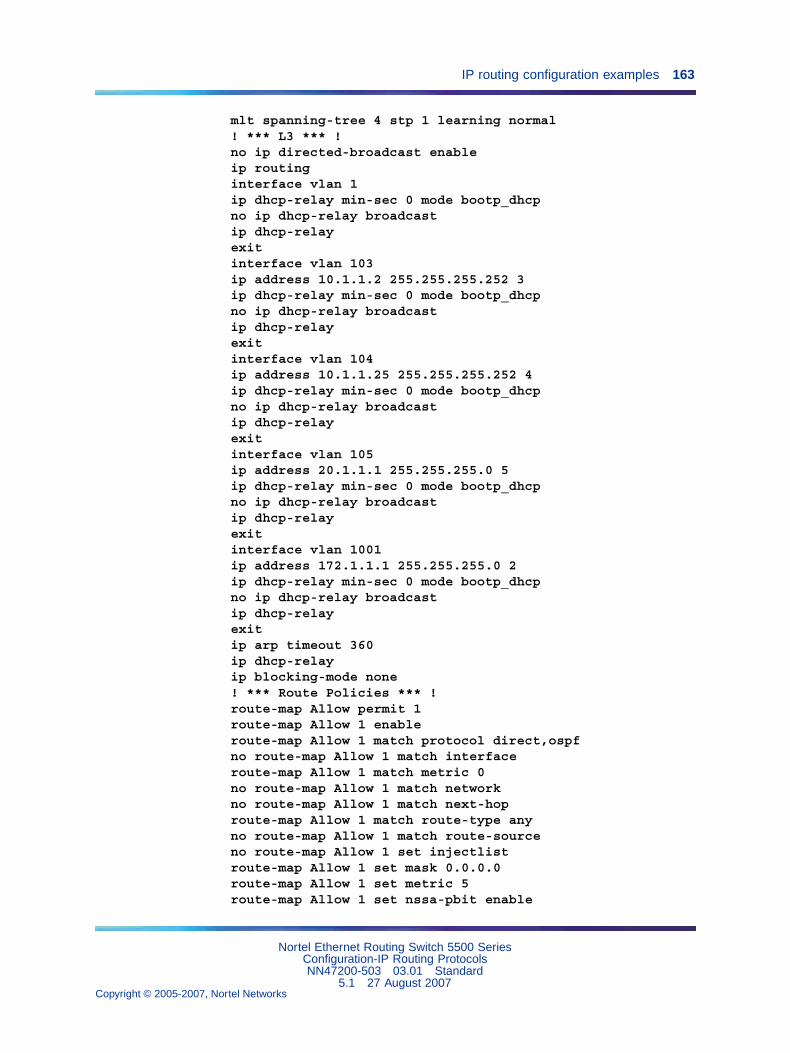
IP routing configuration examples 163
mlt spanning-tree 4 stp 1 learning normal! *** L3 *** !no ip directed-broadcast enableip routinginterface vlan 1ip dhcp-relay min-sec 0 mode bootp_dhcpno ip dhcp-relay broadcastip dhcp-relayexitinterface vlan 103ip address 10.1.1.2 255.255.255.252 3ip dhcp-relay min-sec 0 mode bootp_dhcpno ip dhcp-relay broadcastip dhcp-relayexitinterface vlan 104ip address 10.1.1.25 255.255.255.252 4ip dhcp-relay min-sec 0 mode bootp_dhcpno ip dhcp-relay broadcastip dhcp-relayexitinterface vlan 105ip address 20.1.1.1 255.255.255.0 5ip dhcp-relay min-sec 0 mode bootp_dhcpno ip dhcp-relay broadcastip dhcp-relayexitinterface vlan 1001ip address 172.1.1.1 255.255.255.0 2ip dhcp-relay min-sec 0 mode bootp_dhcpno ip dhcp-relay broadcastip dhcp-relayexitip arp timeout 360ip dhcp-relayip blocking-mode none! *** Route Policies *** !route-map Allow permit 1route-map Allow 1 enableroute-map Allow 1 match protocol direct,ospfno route-map Allow 1 match interfaceroute-map Allow 1 match metric 0no route-map Allow 1 match networkno route-map Allow 1 match next-hoproute-map Allow 1 match route-type anyno route-map Allow 1 match route-sourceno route-map Allow 1 set injectlistroute-map Allow 1 set mask 0.0.0.0route-map Allow 1 set metric 5route-map Allow 1 set nssa-pbit enable
Nortel Ethernet Routing Switch 5500 SeriesConfiguration-IP Routing ProtocolsNN47200-503 03.01 Standard
5.1 27 August 2007Copyright © 2005-2007, Nortel Networks
.
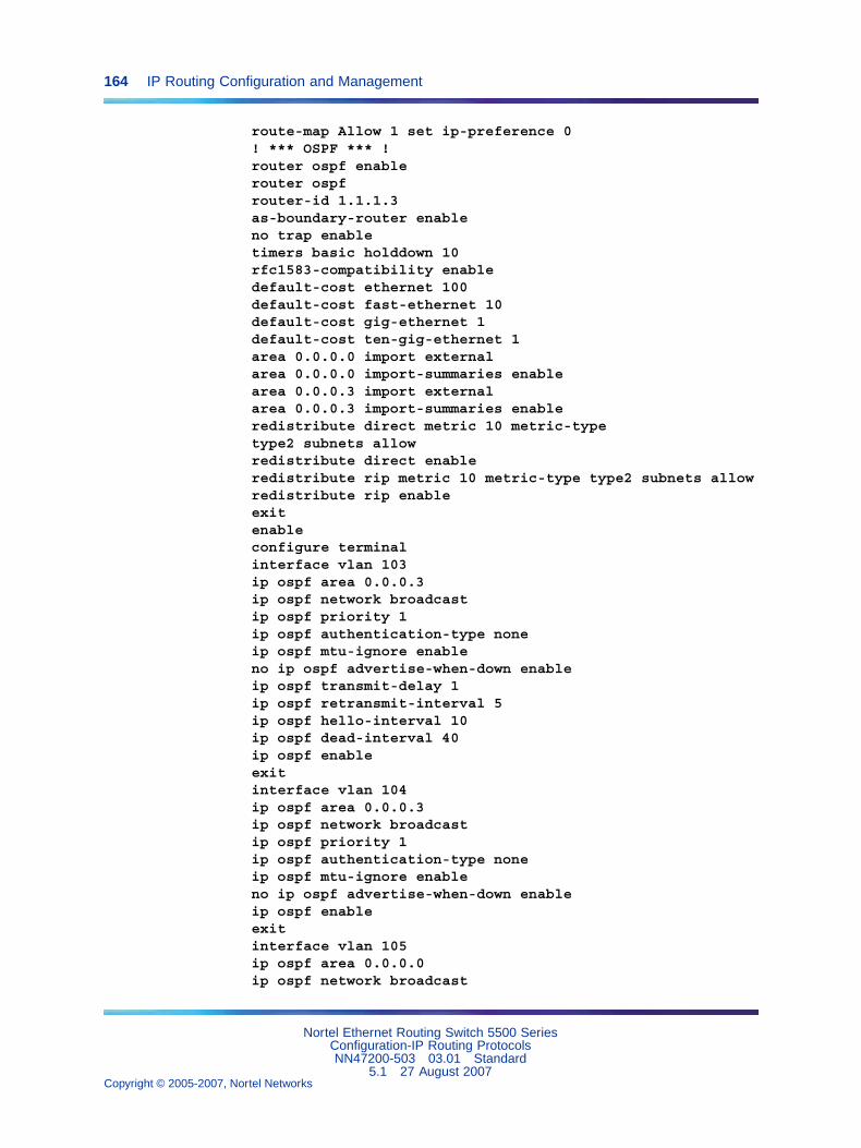
164 IP Routing Configuration and Management
route-map Allow 1 set ip-preference 0! *** OSPF *** !router ospf enablerouter ospfrouter-id 1.1.1.3as-boundary-router enableno trap enabletimers basic holddown 10rfc1583-compatibility enabledefault-cost ethernet 100default-cost fast-ethernet 10default-cost gig-ethernet 1default-cost ten-gig-ethernet 1area 0.0.0.0 import externalarea 0.0.0.0 import-summaries enablearea 0.0.0.3 import externalarea 0.0.0.3 import-summaries enableredistribute direct metric 10 metric-typetype2 subnets allowredistribute direct enableredistribute rip metric 10 metric-type type2 subnets allowredistribute rip enableexitenableconfigure terminalinterface vlan 103ip ospf area 0.0.0.3ip ospf network broadcastip ospf priority 1ip ospf authentication-type noneip ospf mtu-ignore enableno ip ospf advertise-when-down enableip ospf transmit-delay 1ip ospf retransmit-interval 5ip ospf hello-interval 10ip ospf dead-interval 40ip ospf enableexitinterface vlan 104ip ospf area 0.0.0.3ip ospf network broadcastip ospf priority 1ip ospf authentication-type noneip ospf mtu-ignore enableno ip ospf advertise-when-down enableip ospf enableexitinterface vlan 105ip ospf area 0.0.0.0ip ospf network broadcast
Nortel Ethernet Routing Switch 5500 SeriesConfiguration-IP Routing ProtocolsNN47200-503 03.01 Standard
5.1 27 August 2007Copyright © 2005-2007, Nortel Networks
.
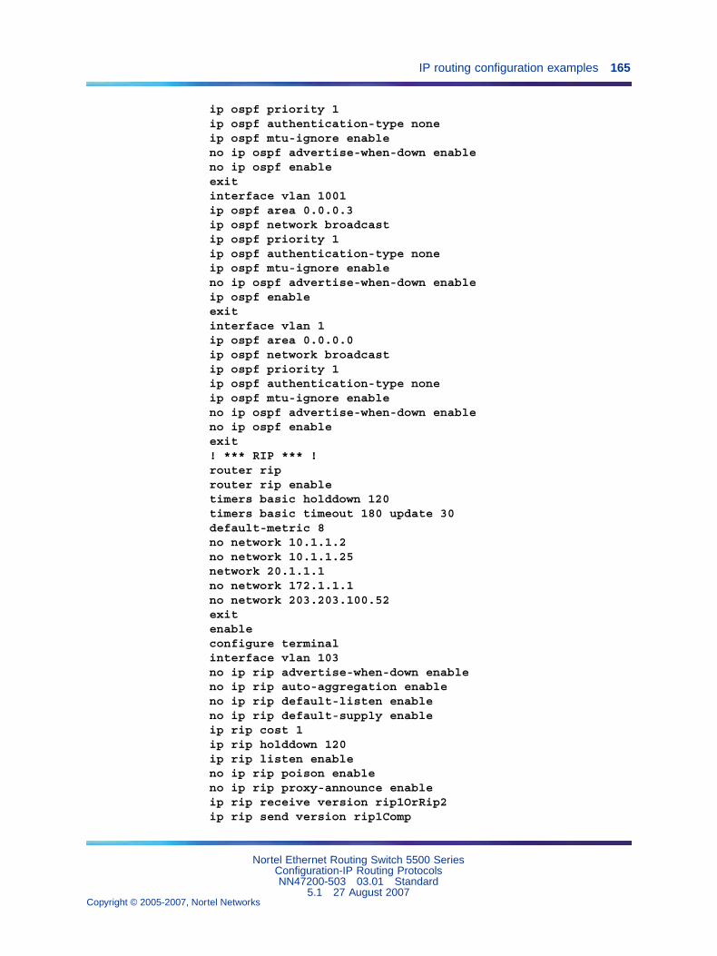
IP routing configuration examples 165
ip ospf priority 1ip ospf authentication-type noneip ospf mtu-ignore enableno ip ospf advertise-when-down enableno ip ospf enableexitinterface vlan 1001ip ospf area 0.0.0.3ip ospf network broadcastip ospf priority 1ip ospf authentication-type noneip ospf mtu-ignore enableno ip ospf advertise-when-down enableip ospf enableexitinterface vlan 1ip ospf area 0.0.0.0ip ospf network broadcastip ospf priority 1ip ospf authentication-type noneip ospf mtu-ignore enableno ip ospf advertise-when-down enableno ip ospf enableexit! *** RIP *** !router riprouter rip enabletimers basic holddown 120timers basic timeout 180 update 30default-metric 8no network 10.1.1.2no network 10.1.1.25network 20.1.1.1no network 172.1.1.1no network 203.203.100.52exitenableconfigure terminalinterface vlan 103no ip rip advertise-when-down enableno ip rip auto-aggregation enableno ip rip default-listen enableno ip rip default-supply enableip rip cost 1ip rip holddown 120ip rip listen enableno ip rip poison enableno ip rip proxy-announce enableip rip receive version rip1OrRip2ip rip send version rip1Comp
Nortel Ethernet Routing Switch 5500 SeriesConfiguration-IP Routing ProtocolsNN47200-503 03.01 Standard
5.1 27 August 2007Copyright © 2005-2007, Nortel Networks
.
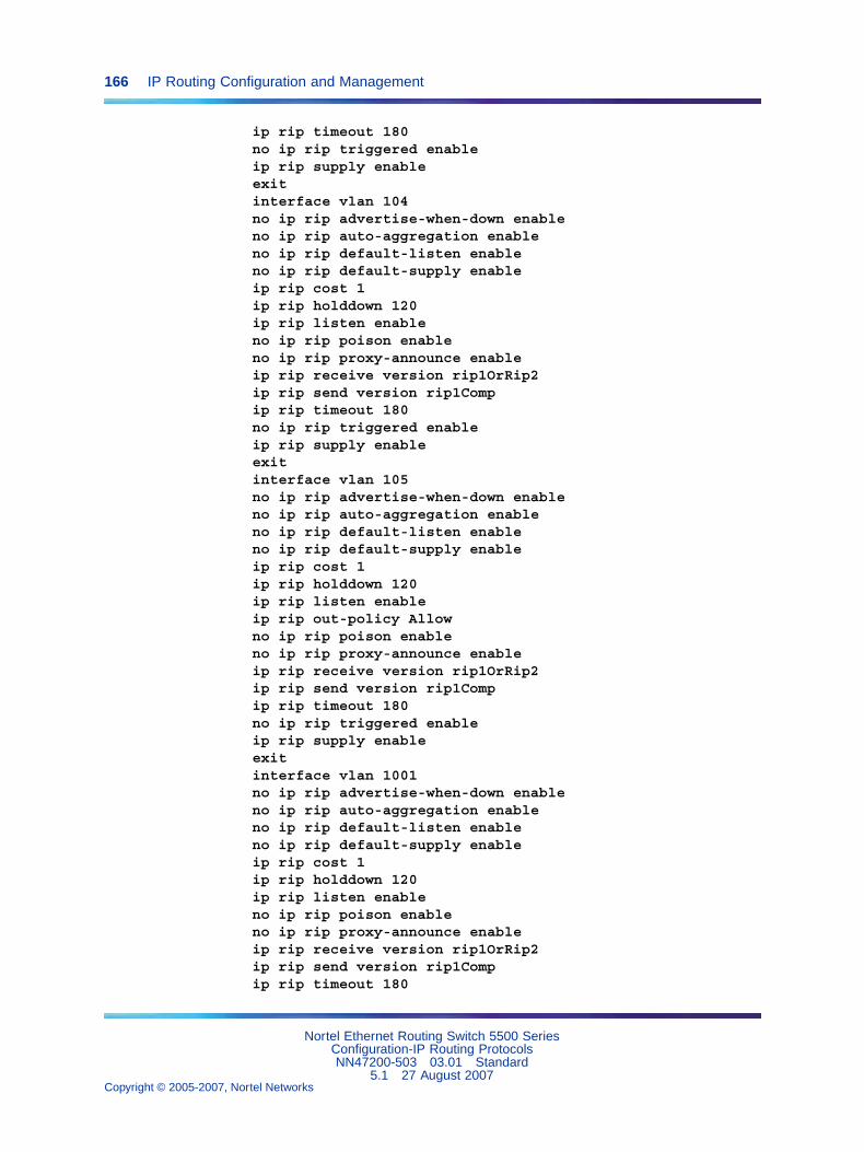
166 IP Routing Configuration and Management
ip rip timeout 180no ip rip triggered enableip rip supply enableexitinterface vlan 104no ip rip advertise-when-down enableno ip rip auto-aggregation enableno ip rip default-listen enableno ip rip default-supply enableip rip cost 1ip rip holddown 120ip rip listen enableno ip rip poison enableno ip rip proxy-announce enableip rip receive version rip1OrRip2ip rip send version rip1Compip rip timeout 180no ip rip triggered enableip rip supply enableexitinterface vlan 105no ip rip advertise-when-down enableno ip rip auto-aggregation enableno ip rip default-listen enableno ip rip default-supply enableip rip cost 1ip rip holddown 120ip rip listen enableip rip out-policy Allowno ip rip poison enableno ip rip proxy-announce enableip rip receive version rip1OrRip2ip rip send version rip1Compip rip timeout 180no ip rip triggered enableip rip supply enableexitinterface vlan 1001no ip rip advertise-when-down enableno ip rip auto-aggregation enableno ip rip default-listen enableno ip rip default-supply enableip rip cost 1ip rip holddown 120ip rip listen enableno ip rip poison enableno ip rip proxy-announce enableip rip receive version rip1OrRip2ip rip send version rip1Compip rip timeout 180
Nortel Ethernet Routing Switch 5500 SeriesConfiguration-IP Routing ProtocolsNN47200-503 03.01 Standard
5.1 27 August 2007Copyright © 2005-2007, Nortel Networks
.
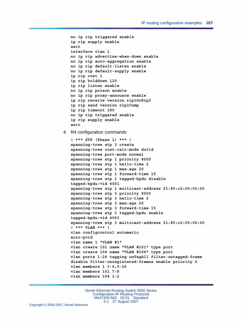
IP routing configuration examples 167
no ip rip triggered enableip rip supply enableexitinterface vlan 1no ip rip advertise-when-down enableno ip rip auto-aggregation enableno ip rip default-listen enableno ip rip default-supply enableip rip cost 1ip rip holddown 120ip rip listen enableno ip rip poison enableno ip rip proxy-announce enableip rip receive version rip1OrRip2ip rip send version rip1Compip rip timeout 180no ip rip triggered enableip rip supply enableexit
4. R4 configuration commands
! *** STP (Phase 1) *** !spanning-tree stp 3 createspanning-tree cost-calc-mode dot1dspanning-tree port-mode normalspanning-tree stp 1 priority 8000spanning-tree stp 1 hello-time 2spanning-tree stp 1 max-age 20spanning-tree stp 1 forward-time 15spanning-tree stp 1 tagged-bpdu disabletagged-bpdu-vid 4001spanning-tree stp 1 multicast-address 01:80:c2:00:00:00spanning-tree stp 3 priority 8000spanning-tree stp 3 hello-time 2spanning-tree stp 3 max-age 20spanning-tree stp 3 forward-time 15spanning-tree stp 3 tagged-bpdu enabletagged-bpdu-vid 4003spanning-tree stp 3 multicast-address 01:80:c2:00:00:00! *** VLAN *** !vlan configcontrol automaticauto-pvidvlan name 1 "VLAN #1"vlan create 101 name "VLAN #101" type portvlan create 104 name "VLAN #104" type portvlan ports 1-26 tagging unTagAll filter-untagged-framedisable filter-unregistered-frames enable priority 0vlan members 1 3-6,9-26vlan members 101 7-8vlan members 104 1-2
Nortel Ethernet Routing Switch 5500 SeriesConfiguration-IP Routing ProtocolsNN47200-503 03.01 Standard
5.1 27 August 2007Copyright © 2005-2007, Nortel Networks
.
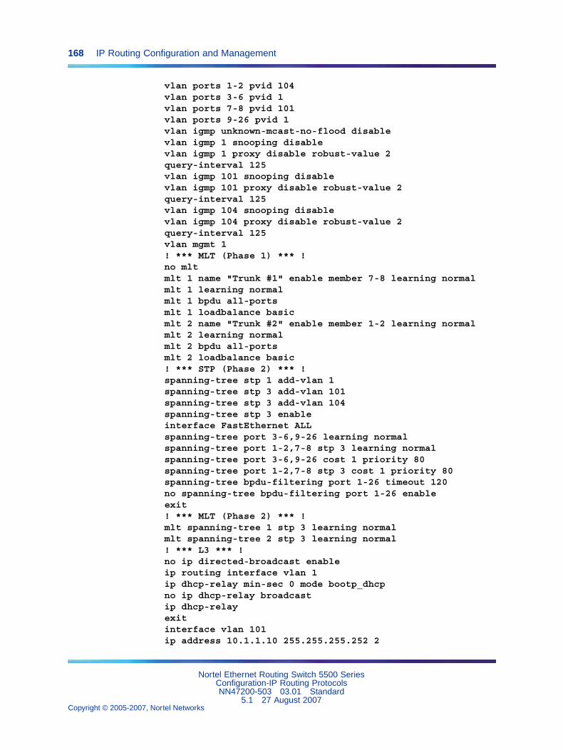
168 IP Routing Configuration and Management
vlan ports 1-2 pvid 104vlan ports 3-6 pvid 1vlan ports 7-8 pvid 101vlan ports 9-26 pvid 1vlan igmp unknown-mcast-no-flood disablevlan igmp 1 snooping disablevlan igmp 1 proxy disable robust-value 2query-interval 125vlan igmp 101 snooping disablevlan igmp 101 proxy disable robust-value 2query-interval 125vlan igmp 104 snooping disablevlan igmp 104 proxy disable robust-value 2query-interval 125vlan mgmt 1! *** MLT (Phase 1) *** !no mltmlt 1 name "Trunk #1" enable member 7-8 learning normalmlt 1 learning normalmlt 1 bpdu all-portsmlt 1 loadbalance basicmlt 2 name "Trunk #2" enable member 1-2 learning normalmlt 2 learning normalmlt 2 bpdu all-portsmlt 2 loadbalance basic! *** STP (Phase 2) *** !spanning-tree stp 1 add-vlan 1spanning-tree stp 3 add-vlan 101spanning-tree stp 3 add-vlan 104spanning-tree stp 3 enableinterface FastEthernet ALLspanning-tree port 3-6,9-26 learning normalspanning-tree port 1-2,7-8 stp 3 learning normalspanning-tree port 3-6,9-26 cost 1 priority 80spanning-tree port 1-2,7-8 stp 3 cost 1 priority 80spanning-tree bpdu-filtering port 1-26 timeout 120no spanning-tree bpdu-filtering port 1-26 enableexit! *** MLT (Phase 2) *** !mlt spanning-tree 1 stp 3 learning normalmlt spanning-tree 2 stp 3 learning normal! *** L3 *** !no ip directed-broadcast enableip routing interface vlan 1ip dhcp-relay min-sec 0 mode bootp_dhcpno ip dhcp-relay broadcastip dhcp-relayexitinterface vlan 101ip address 10.1.1.10 255.255.255.252 2
Nortel Ethernet Routing Switch 5500 SeriesConfiguration-IP Routing ProtocolsNN47200-503 03.01 Standard
5.1 27 August 2007Copyright © 2005-2007, Nortel Networks
.
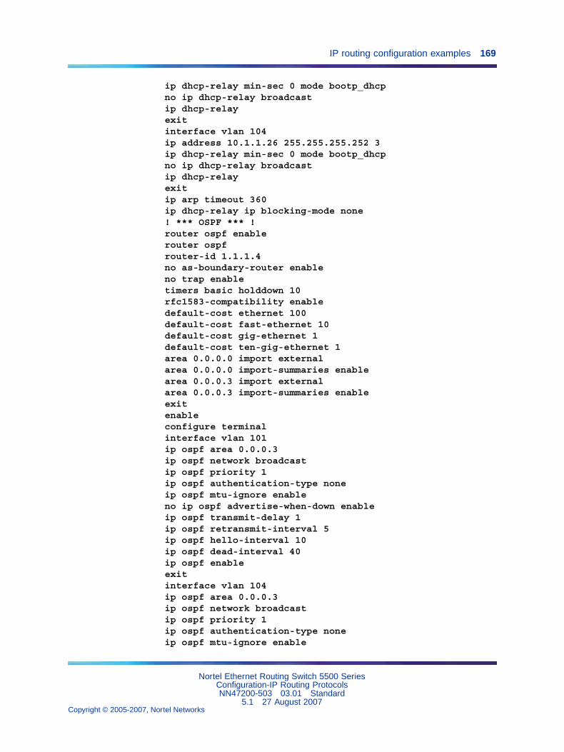
IP routing configuration examples 169
ip dhcp-relay min-sec 0 mode bootp_dhcpno ip dhcp-relay broadcastip dhcp-relayexitinterface vlan 104ip address 10.1.1.26 255.255.255.252 3ip dhcp-relay min-sec 0 mode bootp_dhcpno ip dhcp-relay broadcastip dhcp-relayexitip arp timeout 360ip dhcp-relay ip blocking-mode none! *** OSPF *** !router ospf enablerouter ospfrouter-id 1.1.1.4no as-boundary-router enableno trap enabletimers basic holddown 10rfc1583-compatibility enabledefault-cost ethernet 100default-cost fast-ethernet 10default-cost gig-ethernet 1default-cost ten-gig-ethernet 1area 0.0.0.0 import externalarea 0.0.0.0 import-summaries enablearea 0.0.0.3 import externalarea 0.0.0.3 import-summaries enableexitenableconfigure terminalinterface vlan 101ip ospf area 0.0.0.3ip ospf network broadcastip ospf priority 1ip ospf authentication-type noneip ospf mtu-ignore enableno ip ospf advertise-when-down enableip ospf transmit-delay 1ip ospf retransmit-interval 5ip ospf hello-interval 10ip ospf dead-interval 40ip ospf enableexitinterface vlan 104ip ospf area 0.0.0.3ip ospf network broadcastip ospf priority 1ip ospf authentication-type noneip ospf mtu-ignore enable
Nortel Ethernet Routing Switch 5500 SeriesConfiguration-IP Routing ProtocolsNN47200-503 03.01 Standard
5.1 27 August 2007Copyright © 2005-2007, Nortel Networks
.
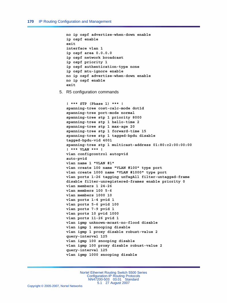
170 IP Routing Configuration and Management
no ip ospf advertise-when-down enableip ospf enableexitinterface vlan 1ip ospf area 0.0.0.0ip ospf network broadcastip ospf priority 1ip ospf authentication-type noneip ospf mtu-ignore enableno ip ospf advertise-when-down enableno ip ospf enableexit
5. R5 configuration commands
! *** STP (Phase 1) *** !spanning-tree cost-calc-mode dot1dspanning-tree port-mode normalspanning-tree stp 1 priority 8000spanning-tree stp 1 hello-time 2spanning-tree stp 1 max-age 20spanning-tree stp 1 forward-time 15spanning-tree stp 1 tagged-bpdu disabletagged-bpdu-vid 4001spanning-tree stp 1 multicast-address 01:80:c2:00:00:00! *** VLAN *** !vlan configcontrol autopvidauto-pvidvlan name 1 "VLAN #1"vlan create 100 name "VLAN #100" type portvlan create 1000 name "VLAN #1000" type portvlan ports 1-26 tagging unTagAll filter-untagged-framedisable filter-unregistered-frames enable priority 0vlan members 1 24-26vlan members 100 5-6vlan members 1000 10vlan ports 1-4 pvid 1vlan ports 5-6 pvid 100vlan ports 7-9 pvid 1vlan ports 10 pvid 1000vlan ports 11-26 pvid 1vlan igmp unknown-mcast-no-flood disablevlan igmp 1 snooping disablevlan igmp 1 proxy disable robust-value 2query-interval 125vlan igmp 100 snooping disablevlan igmp 100 proxy disable robust-value 2query-interval 125vlan igmp 1000 snooping disable
Nortel Ethernet Routing Switch 5500 SeriesConfiguration-IP Routing ProtocolsNN47200-503 03.01 Standard
5.1 27 August 2007Copyright © 2005-2007, Nortel Networks
.
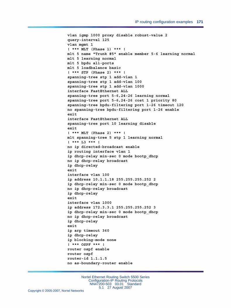
IP routing configuration examples 171
vlan igmp 1000 proxy disable robust-value 2query-interval 125vlan mgmt 1! *** MLT (Phase 1) *** !mlt 5 name "Trunk #5" enable member 5-6 learning normalmlt 5 learning normalmlt 5 bpdu all-portsmlt 5 loadbalance basic! *** STP (Phase 2) *** !spanning-tree stp 1 add-vlan 1spanning-tree stp 1 add-vlan 100spanning-tree stp 1 add-vlan 1000interface FastEthernet ALLspanning-tree port 5-6,24-26 learning normalspanning-tree port 5-6,24-26 cost 1 priority 80spanning-tree bpdu-filtering port 1-26 timeout 120no spanning-tree bpdu-filtering port 1-26 enableexitinterface FastEthernet ALLspanning-tree port 10 learning disableexit! *** MLT (Phase 2) *** !mlt spanning-tree 5 stp 1 learning normal! *** L3 *** !no ip directed-broadcast enableip routing interface vlan 1ip dhcp-relay min-sec 0 mode bootp_dhcpno ip dhcp-relay broadcastip dhcp-relayexitinterface vlan 100ip address 10.1.1.18 255.255.255.252 2ip dhcp-relay min-sec 0 mode bootp_dhcpno ip dhcp-relay broadcastip dhcp-relayexitinterface vlan 1000ip address 172.3.3.1 255.255.255.252 3ip dhcp-relay min-sec 0 mode bootp_dhcpno ip dhcp-relay broadcastip dhcp-relayexitip arp timeout 360ip dhcp-relayip blocking-mode none! *** OSPF *** !router ospf enablerouter ospfrouter-id 1.1.1.5no as-boundary-router enable
Nortel Ethernet Routing Switch 5500 SeriesConfiguration-IP Routing ProtocolsNN47200-503 03.01 Standard
5.1 27 August 2007Copyright © 2005-2007, Nortel Networks
.
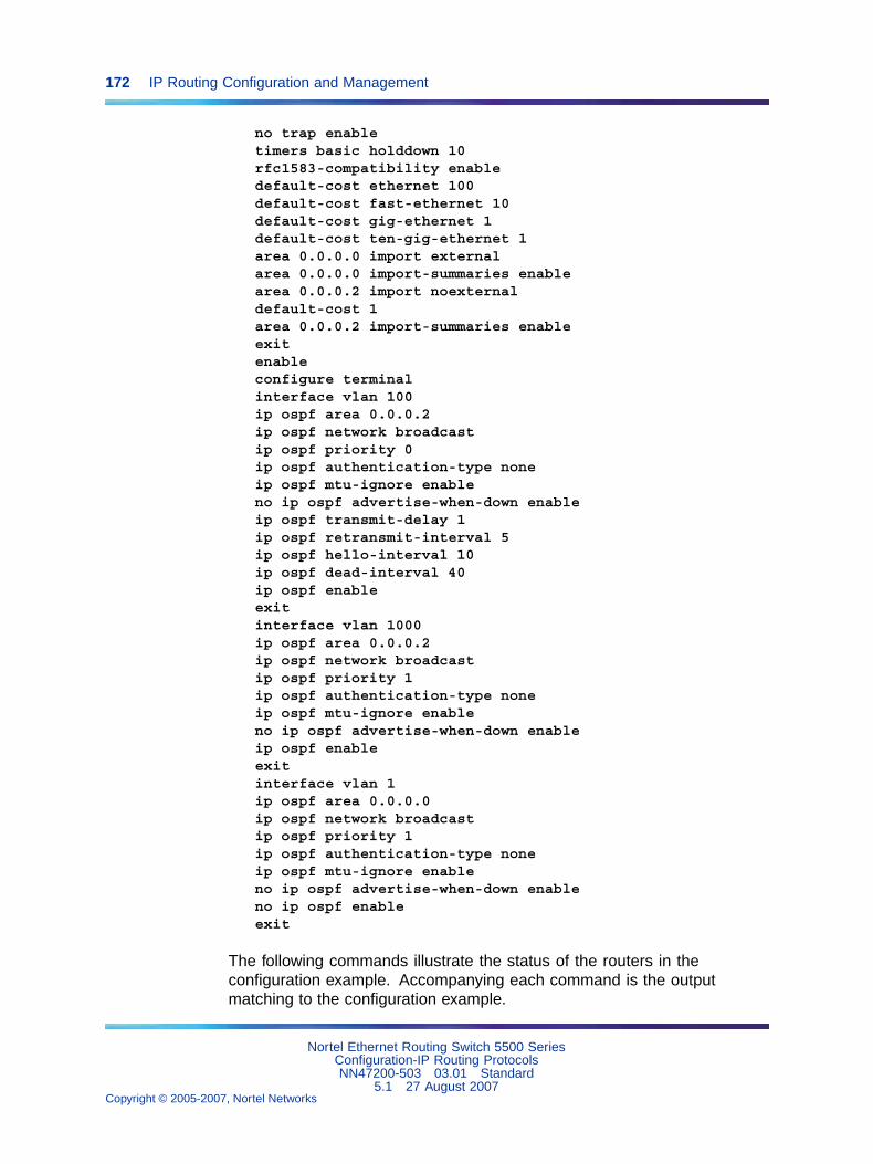
172 IP Routing Configuration and Management
no trap enabletimers basic holddown 10rfc1583-compatibility enabledefault-cost ethernet 100default-cost fast-ethernet 10default-cost gig-ethernet 1default-cost ten-gig-ethernet 1area 0.0.0.0 import externalarea 0.0.0.0 import-summaries enablearea 0.0.0.2 import noexternaldefault-cost 1area 0.0.0.2 import-summaries enableexitenableconfigure terminalinterface vlan 100ip ospf area 0.0.0.2ip ospf network broadcastip ospf priority 0ip ospf authentication-type noneip ospf mtu-ignore enableno ip ospf advertise-when-down enableip ospf transmit-delay 1ip ospf retransmit-interval 5ip ospf hello-interval 10ip ospf dead-interval 40ip ospf enableexitinterface vlan 1000ip ospf area 0.0.0.2ip ospf network broadcastip ospf priority 1ip ospf authentication-type noneip ospf mtu-ignore enableno ip ospf advertise-when-down enableip ospf enableexitinterface vlan 1ip ospf area 0.0.0.0ip ospf network broadcastip ospf priority 1ip ospf authentication-type noneip ospf mtu-ignore enableno ip ospf advertise-when-down enableno ip ospf enableexit
The following commands illustrate the status of the routers in theconfiguration example. Accompanying each command is the outputmatching to the configuration example.
Nortel Ethernet Routing Switch 5500 SeriesConfiguration-IP Routing ProtocolsNN47200-503 03.01 Standard
5.1 27 August 2007Copyright © 2005-2007, Nortel Networks
.
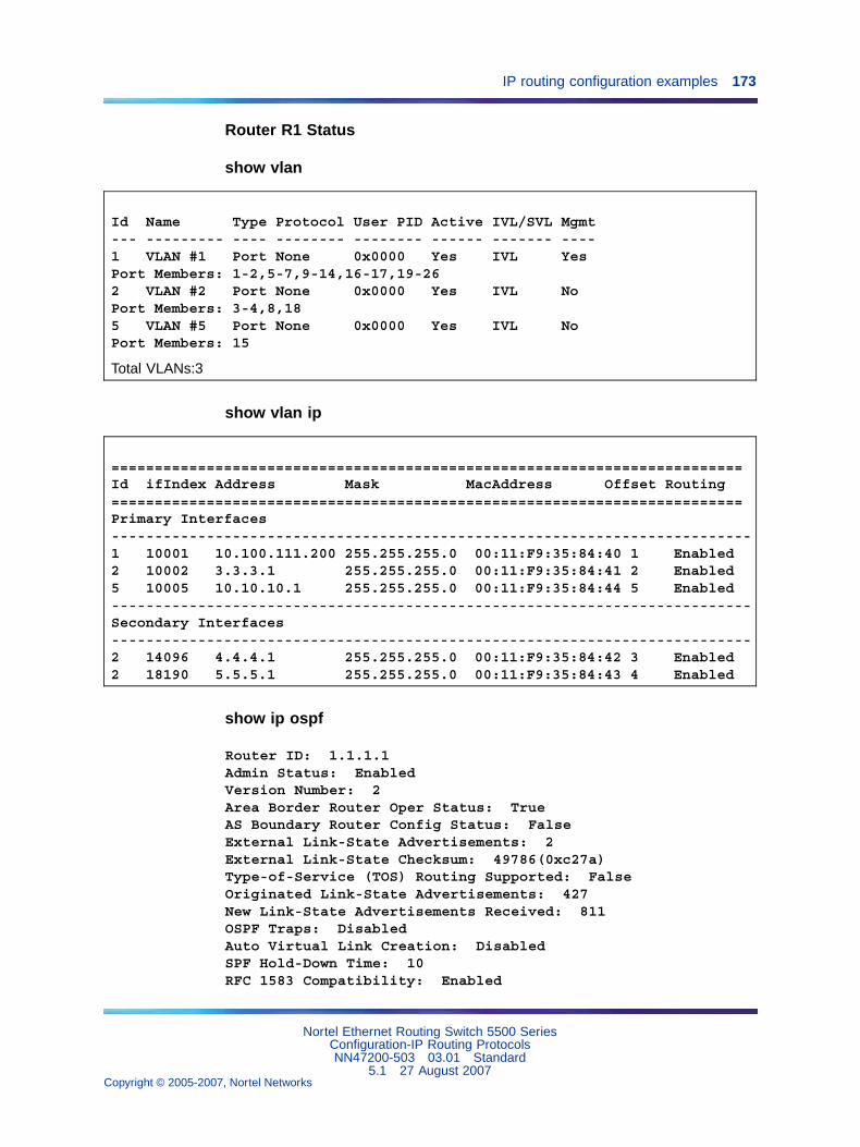
IP routing configuration examples 173
Router R1 Status
show vlan
Id Name Type Protocol User PID Active IVL/SVL Mgmt--- --------- ---- -------- -------- ------ ------- ----1 VLAN #1 Port None 0x0000 Yes IVL YesPort Members: 1-2,5-7,9-14,16-17,19-262 VLAN #2 Port None 0x0000 Yes IVL NoPort Members: 3-4,8,185 VLAN #5 Port None 0x0000 Yes IVL NoPort Members: 15
Total VLANs:3
show vlan ip
=========================================================================Id ifIndex Address Mask MacAddress Offset Routing=========================================================================Primary Interfaces--------------------------------------------------------------------------1 10001 10.100.111.200 255.255.255.0 00:11:F9:35:84:40 1 Enabled2 10002 3.3.3.1 255.255.255.0 00:11:F9:35:84:41 2 Enabled5 10005 10.10.10.1 255.255.255.0 00:11:F9:35:84:44 5 Enabled--------------------------------------------------------------------------Secondary Interfaces--------------------------------------------------------------------------2 14096 4.4.4.1 255.255.255.0 00:11:F9:35:84:42 3 Enabled2 18190 5.5.5.1 255.255.255.0 00:11:F9:35:84:43 4 Enabled
show ip ospf
Router ID: 1.1.1.1Admin Status: EnabledVersion Number: 2Area Border Router Oper Status: TrueAS Boundary Router Config Status: FalseExternal Link-State Advertisements: 2External Link-State Checksum: 49786(0xc27a)Type-of-Service (TOS) Routing Supported: FalseOriginated Link-State Advertisements: 427New Link-State Advertisements Received: 811OSPF Traps: DisabledAuto Virtual Link Creation: DisabledSPF Hold-Down Time: 10RFC 1583 Compatibility: Enabled
Nortel Ethernet Routing Switch 5500 SeriesConfiguration-IP Routing ProtocolsNN47200-503 03.01 Standard
5.1 27 August 2007Copyright © 2005-2007, Nortel Networks
.
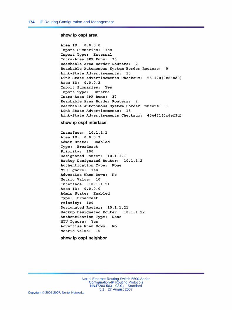
174 IP Routing Configuration and Management
show ip ospf area
Area ID: 0.0.0.0Import Summaries: YesImport Type: ExternalIntra-Area SPF Runs: 35Reachable Area Border Routers: 2Reachable Autonomous System Border Routers: 0Link-State Advertisements: 15Link-State Advertisements Checksum: 551120(0x868d0)Area ID: 0.0.0.3Import Summaries: YesImport Type: ExternalIntra-Area SPF Runs: 37Reachable Area Border Routers: 2Reachable Autonomous System Border Routers: 1Link-State Advertisements: 13Link-State Advertisements Checksum: 454461(0x6ef3d)
show ip ospf interface
Interface: 10.1.1.1Area ID: 0.0.0.3Admin State: EnabledType: BroadcastPriority: 100Designated Router: 10.1.1.1Backup Designated Router: 10.1.1.2Authentication Type: NoneMTU Ignore: YesAdvertise When Down: NoMetric Value: 10Interface: 10.1.1.21Area ID: 0.0.0.0Admin State: EnabledType: BroadcastPriority: 100Designated Router: 10.1.1.21Backup Designated Router: 10.1.1.22Authentication Type: NoneMTU Ignore: YesAdvertise When Down: NoMetric Value: 10
show ip ospf neighbor
Nortel Ethernet Routing Switch 5500 SeriesConfiguration-IP Routing ProtocolsNN47200-503 03.01 Standard
5.1 27 August 2007Copyright © 2005-2007, Nortel Networks
.
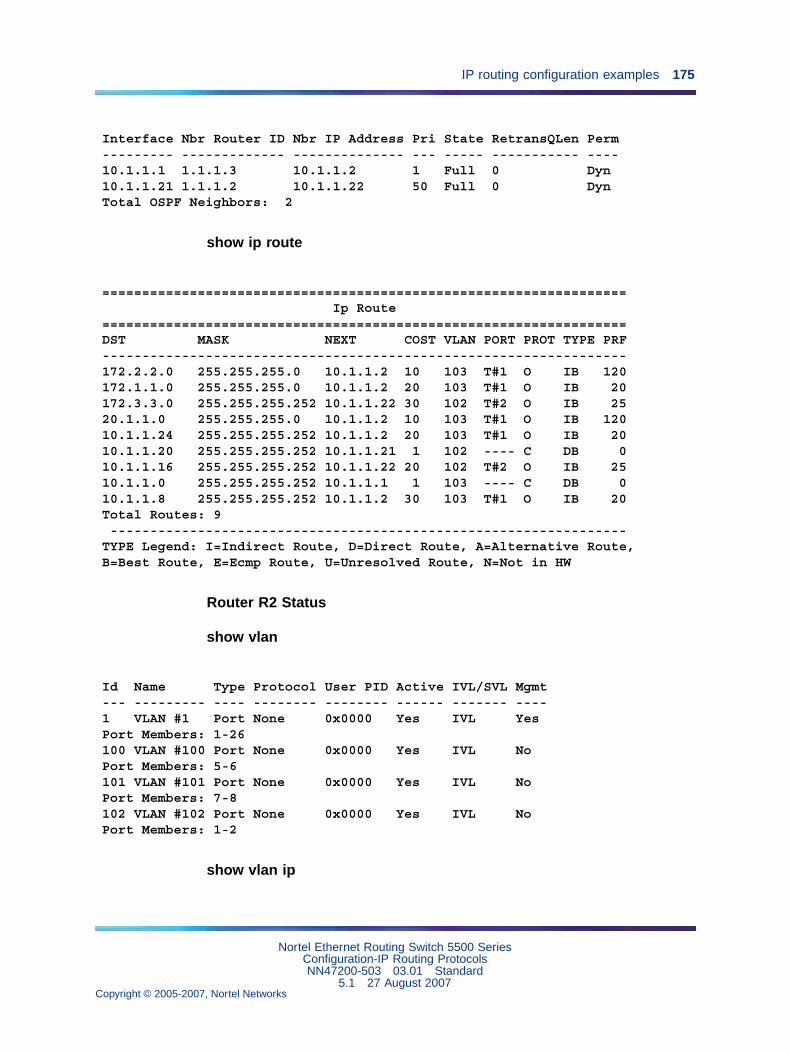
IP routing configuration examples 175
Interface Nbr Router ID Nbr IP Address Pri State RetransQLen Perm--------- ------------- -------------- --- ----- ----------- ----10.1.1.1 1.1.1.3 10.1.1.2 1 Full 0 Dyn10.1.1.21 1.1.1.2 10.1.1.22 50 Full 0 DynTotal OSPF Neighbors: 2
show ip route
==================================================================Ip Route
==================================================================DST MASK NEXT COST VLAN PORT PROT TYPE PRF------------------------------------------------------------------172.2.2.0 255.255.255.0 10.1.1.2 10 103 T#1 O IB 120172.1.1.0 255.255.255.0 10.1.1.2 20 103 T#1 O IB 20172.3.3.0 255.255.255.252 10.1.1.22 30 102 T#2 O IB 2520.1.1.0 255.255.255.0 10.1.1.2 10 103 T#1 O IB 12010.1.1.24 255.255.255.252 10.1.1.2 20 103 T#1 O IB 2010.1.1.20 255.255.255.252 10.1.1.21 1 102 ---- C DB 010.1.1.16 255.255.255.252 10.1.1.22 20 102 T#2 O IB 2510.1.1.0 255.255.255.252 10.1.1.1 1 103 ---- C DB 010.1.1.8 255.255.255.252 10.1.1.2 30 103 T#1 O IB 20Total Routes: 9-----------------------------------------------------------------
TYPE Legend: I=Indirect Route, D=Direct Route, A=Alternative Route,B=Best Route, E=Ecmp Route, U=Unresolved Route, N=Not in HW
Router R2 Status
show vlan
Id Name Type Protocol User PID Active IVL/SVL Mgmt--- --------- ---- -------- -------- ------ ------- ----1 VLAN #1 Port None 0x0000 Yes IVL YesPort Members: 1-26100 VLAN #100 Port None 0x0000 Yes IVL NoPort Members: 5-6101 VLAN #101 Port None 0x0000 Yes IVL NoPort Members: 7-8102 VLAN #102 Port None 0x0000 Yes IVL NoPort Members: 1-2
show vlan ip
Nortel Ethernet Routing Switch 5500 SeriesConfiguration-IP Routing ProtocolsNN47200-503 03.01 Standard
5.1 27 August 2007Copyright © 2005-2007, Nortel Networks
.
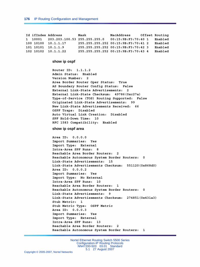
176 IP Routing Configuration and Management
Id ifIndex Address Mask MacAddress Offset Routing1 10001 203.203.100.53 255.255.255.0 00:15:9B:F3:70:40 1 Enabled100 10100 10.1.1.17 255.255.255.252 00:15:9B:F3:70:41 2 Enabled101 10101 10.1.1.9 255.255.255.252 00:15:9B:F3:70:42 3 Enabled102 10102 10.1.1.22 255.255.255.252 00:15:9B:F3:70:43 4 Enabled
show ip ospf
Router ID: 1.1.1.2Admin Status: EnabledVersion Number: 2Area Border Router Oper Status: TrueAS Boundary Router Config Status: FalseExternal Link-State Advertisements: 2External Link-State Checksum: 49786(0xc27a)Type-of-Service (TOS) Routing Supported: FalseOriginated Link-State Advertisements: 99New Link-State Advertisements Received: 66OSPF Traps: DisabledAuto Virtual Link Creation: DisabledSPF Hold-Down Time: 10RFC 1583 Compatibility: Enabled
show ip ospf area
Area ID: 0.0.0.0Import Summaries: YesImport Type: ExternalIntra-Area SPF Runs: 8Reachable Area Border Routers: 2Reachable Autonomous System Border Routers: 0Link-State Advertisements: 15Link-State Advertisements Checksum: 551120(0x868d0)Area ID: 0.0.0.2Import Summaries: YesImport Type: No ExternalIntra-Area SPF Runs: 10Reachable Area Border Routers: 1Reachable Autonomous System Border Routers: 0Link-State Advertisements: 9Link-State Advertisements Checksum: 274851(0x431a3)Stub Metric: 1Stub Metric Type: OSPF MetricArea ID: 0.0.0.3Import Summaries: YesImport Type: ExternalIntra-Area SPF Runs: 13Reachable Area Border Routers: 2Reachable Autonomous System Border Routers: 1
Nortel Ethernet Routing Switch 5500 SeriesConfiguration-IP Routing ProtocolsNN47200-503 03.01 Standard
5.1 27 August 2007Copyright © 2005-2007, Nortel Networks
.
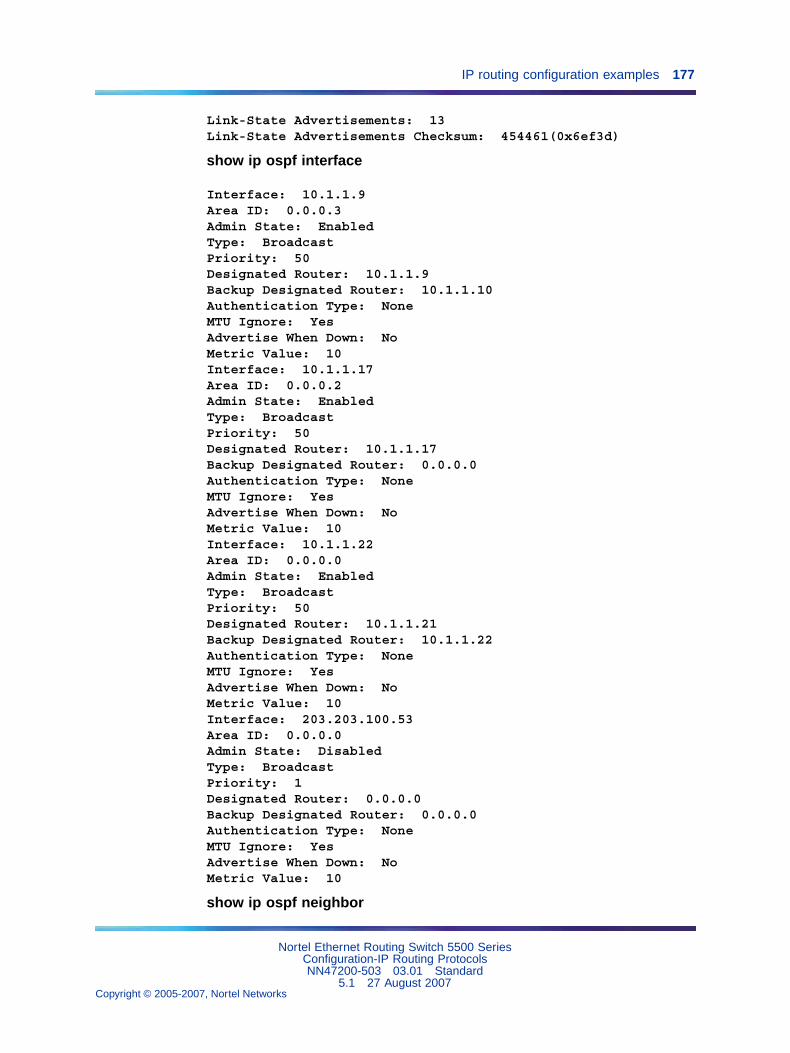
IP routing configuration examples 177
Link-State Advertisements: 13Link-State Advertisements Checksum: 454461(0x6ef3d)
show ip ospf interface
Interface: 10.1.1.9Area ID: 0.0.0.3Admin State: EnabledType: BroadcastPriority: 50Designated Router: 10.1.1.9Backup Designated Router: 10.1.1.10Authentication Type: NoneMTU Ignore: YesAdvertise When Down: NoMetric Value: 10Interface: 10.1.1.17Area ID: 0.0.0.2Admin State: EnabledType: BroadcastPriority: 50Designated Router: 10.1.1.17Backup Designated Router: 0.0.0.0Authentication Type: NoneMTU Ignore: YesAdvertise When Down: NoMetric Value: 10Interface: 10.1.1.22Area ID: 0.0.0.0Admin State: EnabledType: BroadcastPriority: 50Designated Router: 10.1.1.21Backup Designated Router: 10.1.1.22Authentication Type: NoneMTU Ignore: YesAdvertise When Down: NoMetric Value: 10Interface: 203.203.100.53Area ID: 0.0.0.0Admin State: DisabledType: BroadcastPriority: 1Designated Router: 0.0.0.0Backup Designated Router: 0.0.0.0Authentication Type: NoneMTU Ignore: YesAdvertise When Down: NoMetric Value: 10
show ip ospf neighbor
Nortel Ethernet Routing Switch 5500 SeriesConfiguration-IP Routing ProtocolsNN47200-503 03.01 Standard
5.1 27 August 2007Copyright © 2005-2007, Nortel Networks
.
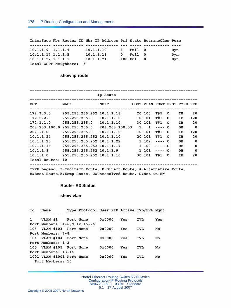
178 IP Routing Configuration and Management
Interface Nbr Router ID Nbr IP Address Pri State RetransQLen Perm--------- ------------- -------------- --- ----- ----------- ----10.1.1.9 1.1.1.4 10.1.1.10 1 Full 0 Dyn10.1.1.17 1.1.1.5 10.1.1.18 0 Full 0 Dyn10.1.1.22 1.1.1.1 10.1.1.21 100 Full 0 DynTotal OSPF Neighbors: 3
show ip route
========================================================================Ip Route
========================================================================DST MASK NEXT COST VLAN PORT PROT TYPE PRF------------------------------------------------------------------------172.3.3.0 255.255.255.252 10.1.1.18 20 100 T#5 O IB 20172.2.2.0 255.255.255.0 10.1.1.10 10 101 T#1 O IB 120172.1.1.0 255.255.255.0 10.1.1.10 30 101 T#1 O IB 20203.203.100.0 255.255.255.0 203.203.100.53 1 1 ---- C DB 020.1.1.0 255.255.255.0 10.1.1.10 10 101 T#1 O IB 12010.1.1.24 255.255.255.252 10.1.1.10 20 101 T#1 O IB 2010.1.1.20 255.255.255.252 10.1.1.22 1 102 ---- C DB 010.1.1.16 255.255.255.252 10.1.1.17 1 100 ---- C DB 010.1.1.8 255.255.255.252 10.1.1.9 1 101 ---- C DB 010.1.1.0 255.255.255.252 10.1.1.10 30 101 T#1 O IB 20Total Routes: 10------------------------------------------------------------------------TYPE Legend: I=Indirect Route, D=Direct Route, A=Alternative Route,B=Best Route,E=Ecmp Route, U=Unresolved Route, N=Not in HW
Router R3 Status
show vlan
Id Name Type Protocol User PID Active IVL/SVL Mgmt--- --------- ---- -------- -------- ------ ------- ----1 VLAN #1 Port None 0x0000 Yes IVL YesPort Members: 4-6,9,12,15-26103 VLAN #103 Port None 0x0000 Yes IVL NoPort Members: 7-8104 VLAN #104 Port None 0x0000 Yes IVL NoPort Members: 1-2105 VLAN #105 Port None 0x0000 Yes IVL NoPort Members: 13-141001 VLAN #1001 Port None 0x0000 Yes IVL No
Port Members: 10
Nortel Ethernet Routing Switch 5500 SeriesConfiguration-IP Routing ProtocolsNN47200-503 03.01 Standard
5.1 27 August 2007Copyright © 2005-2007, Nortel Networks
.
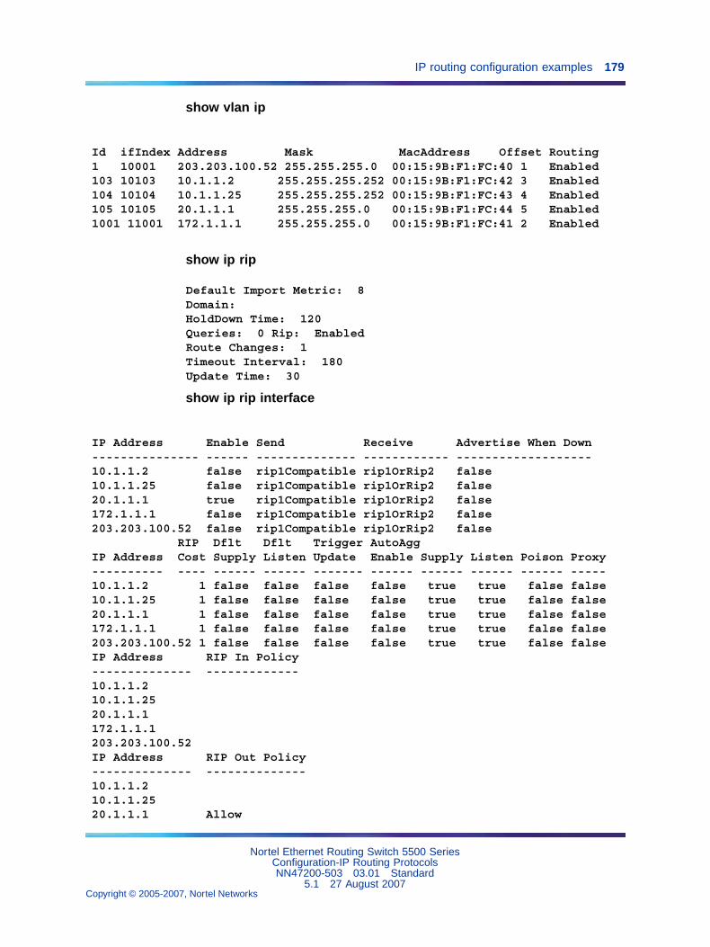
IP routing configuration examples 179
show vlan ip
Id ifIndex Address Mask MacAddress Offset Routing1 10001 203.203.100.52 255.255.255.0 00:15:9B:F1:FC:40 1 Enabled103 10103 10.1.1.2 255.255.255.252 00:15:9B:F1:FC:42 3 Enabled104 10104 10.1.1.25 255.255.255.252 00:15:9B:F1:FC:43 4 Enabled105 10105 20.1.1.1 255.255.255.0 00:15:9B:F1:FC:44 5 Enabled1001 11001 172.1.1.1 255.255.255.0 00:15:9B:F1:FC:41 2 Enabled
show ip rip
Default Import Metric: 8Domain:HoldDown Time: 120Queries: 0 Rip: EnabledRoute Changes: 1Timeout Interval: 180Update Time: 30
show ip rip interface
IP Address Enable Send Receive Advertise When Down--------------- ------ -------------- ------------ -------------------10.1.1.2 false rip1Compatible rip1OrRip2 false10.1.1.25 false rip1Compatible rip1OrRip2 false20.1.1.1 true rip1Compatible rip1OrRip2 false172.1.1.1 false rip1Compatible rip1OrRip2 false203.203.100.52 false rip1Compatible rip1OrRip2 false
RIP Dflt Dflt Trigger AutoAggIP Address Cost Supply Listen Update Enable Supply Listen Poison Proxy---------- ---- ------ ------ ------- ------ ------ ------ ------ -----10.1.1.2 1 false false false false true true false false10.1.1.25 1 false false false false true true false false20.1.1.1 1 false false false false true true false false172.1.1.1 1 false false false false true true false false203.203.100.52 1 false false false false true true false falseIP Address RIP In Policy-------------- -------------10.1.1.210.1.1.2520.1.1.1172.1.1.1203.203.100.52IP Address RIP Out Policy-------------- --------------10.1.1.210.1.1.2520.1.1.1 Allow
Nortel Ethernet Routing Switch 5500 SeriesConfiguration-IP Routing ProtocolsNN47200-503 03.01 Standard
5.1 27 August 2007Copyright © 2005-2007, Nortel Networks
.
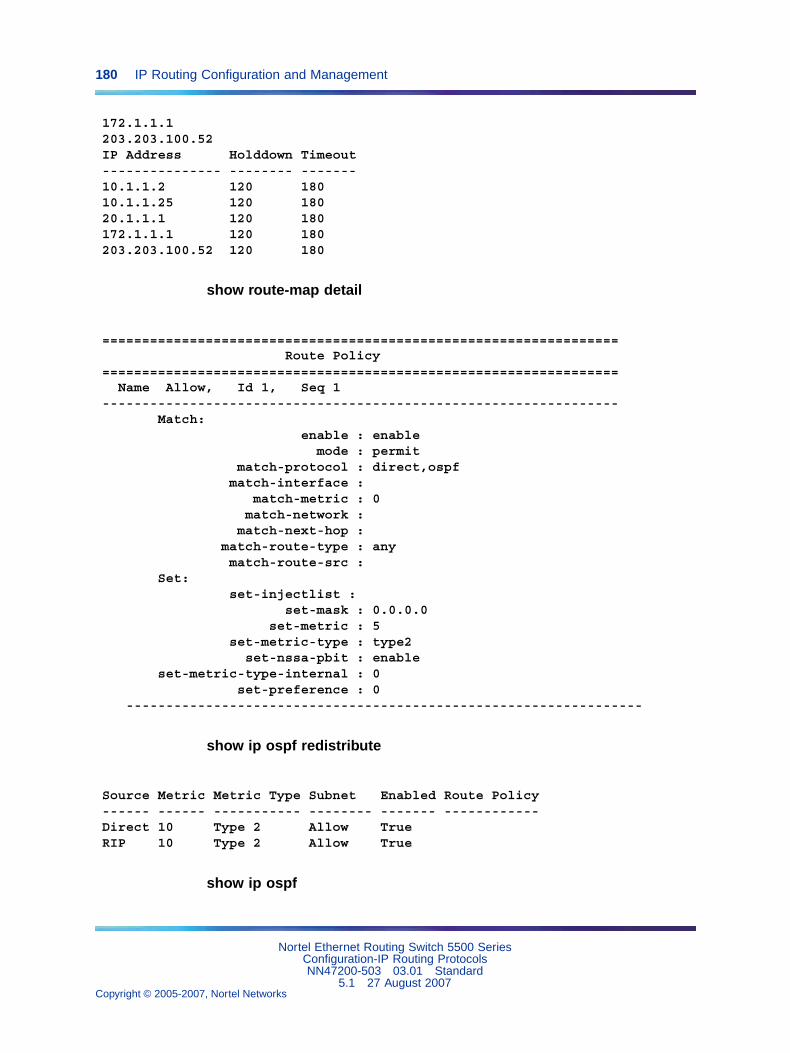
180 IP Routing Configuration and Management
172.1.1.1203.203.100.52IP Address Holddown Timeout--------------- -------- -------10.1.1.2 120 18010.1.1.25 120 18020.1.1.1 120 180172.1.1.1 120 180203.203.100.52 120 180
show route-map detail
=================================================================Route Policy
=================================================================Name Allow, Id 1, Seq 1
-----------------------------------------------------------------Match:
enable : enablemode : permit
match-protocol : direct,ospfmatch-interface :
match-metric : 0match-network :
match-next-hop :match-route-type : anymatch-route-src :
Set:set-injectlist :
set-mask : 0.0.0.0set-metric : 5
set-metric-type : type2set-nssa-pbit : enable
set-metric-type-internal : 0set-preference : 0
-----------------------------------------------------------------
show ip ospf redistribute
Source Metric Metric Type Subnet Enabled Route Policy------ ------ ----------- -------- ------- ------------Direct 10 Type 2 Allow TrueRIP 10 Type 2 Allow True
show ip ospf
Nortel Ethernet Routing Switch 5500 SeriesConfiguration-IP Routing ProtocolsNN47200-503 03.01 Standard
5.1 27 August 2007Copyright © 2005-2007, Nortel Networks
.
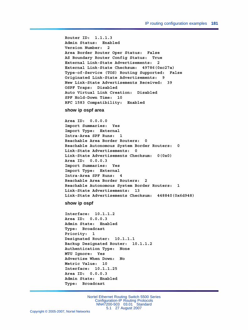
IP routing configuration examples 181
Router ID: 1.1.1.3Admin Status: EnabledVersion Number: 2Area Border Router Oper Status: FalseAS Boundary Router Config Status: TrueExternal Link-State Advertisements: 2External Link-State Checksum: 49786(0xc27a)Type-of-Service (TOS) Routing Supported: FalseOriginated Link-State Advertisements: 9New Link-State Advertisements Received: 39OSPF Traps: DisabledAuto Virtual Link Creation: DisabledSPF Hold-Down Time: 10RFC 1583 Compatibility: Enabled
show ip ospf area
Area ID: 0.0.0.0Import Summaries: YesImport Type: ExternalIntra-Area SPF Runs: 1Reachable Area Border Routers: 0Reachable Autonomous System Border Routers: 0Link-State Advertisements: 0Link-State Advertisements Checksum: 0(0x0)Area ID: 0.0.0.3Import Summaries: YesImport Type: ExternalIntra-Area SPF Runs: 4Reachable Area Border Routers: 2Reachable Autonomous System Border Routers: 1Link-State Advertisements: 13Link-State Advertisements Checksum: 448840(0x6d948)
show ip ospf
Interface: 10.1.1.2Area ID: 0.0.0.3Admin State: EnabledType: BroadcastPriority: 1Designated Router: 10.1.1.1Backup Designated Router: 10.1.1.2Authentication Type: NoneMTU Ignore: YesAdvertise When Down: NoMetric Value: 10Interface: 10.1.1.25Area ID: 0.0.0.3Admin State: EnabledType: Broadcast
Nortel Ethernet Routing Switch 5500 SeriesConfiguration-IP Routing ProtocolsNN47200-503 03.01 Standard
5.1 27 August 2007Copyright © 2005-2007, Nortel Networks
.
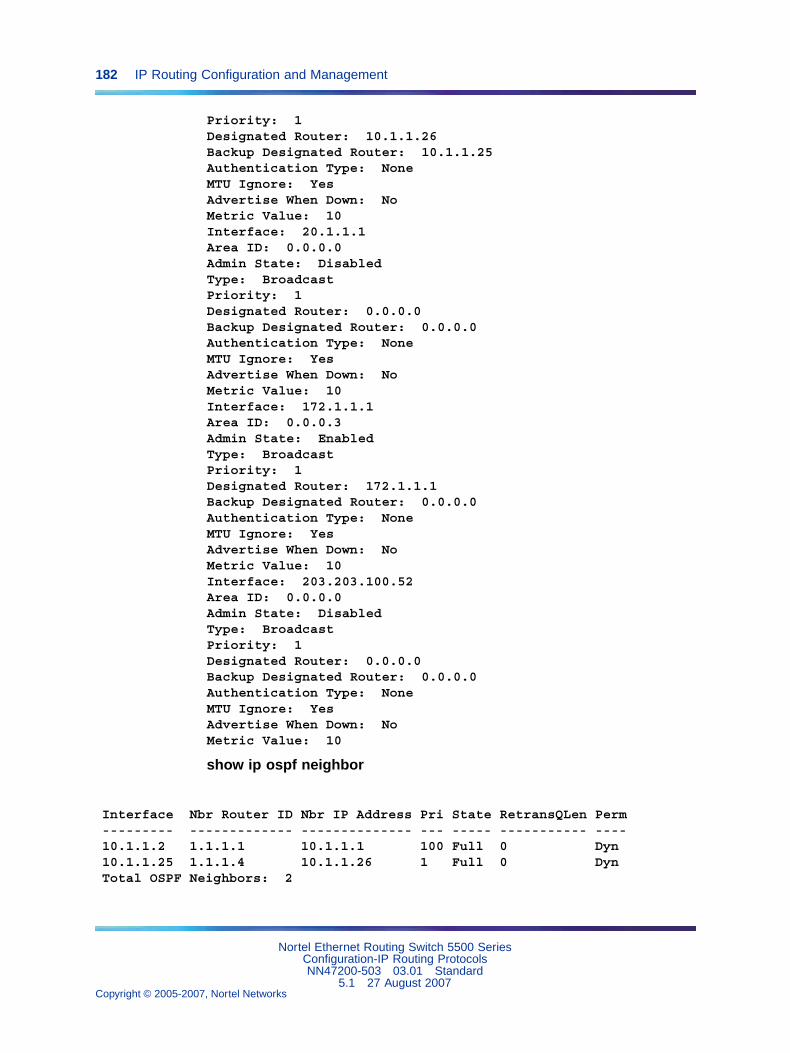
182 IP Routing Configuration and Management
Priority: 1Designated Router: 10.1.1.26Backup Designated Router: 10.1.1.25Authentication Type: NoneMTU Ignore: YesAdvertise When Down: NoMetric Value: 10Interface: 20.1.1.1Area ID: 0.0.0.0Admin State: DisabledType: BroadcastPriority: 1Designated Router: 0.0.0.0Backup Designated Router: 0.0.0.0Authentication Type: NoneMTU Ignore: YesAdvertise When Down: NoMetric Value: 10Interface: 172.1.1.1Area ID: 0.0.0.3Admin State: EnabledType: BroadcastPriority: 1Designated Router: 172.1.1.1Backup Designated Router: 0.0.0.0Authentication Type: NoneMTU Ignore: YesAdvertise When Down: NoMetric Value: 10Interface: 203.203.100.52Area ID: 0.0.0.0Admin State: DisabledType: BroadcastPriority: 1Designated Router: 0.0.0.0Backup Designated Router: 0.0.0.0Authentication Type: NoneMTU Ignore: YesAdvertise When Down: NoMetric Value: 10
show ip ospf neighbor
Interface Nbr Router ID Nbr IP Address Pri State RetransQLen Perm--------- ------------- -------------- --- ----- ----------- ----10.1.1.2 1.1.1.1 10.1.1.1 100 Full 0 Dyn10.1.1.25 1.1.1.4 10.1.1.26 1 Full 0 DynTotal OSPF Neighbors: 2
Nortel Ethernet Routing Switch 5500 SeriesConfiguration-IP Routing ProtocolsNN47200-503 03.01 Standard
5.1 27 August 2007Copyright © 2005-2007, Nortel Networks
.
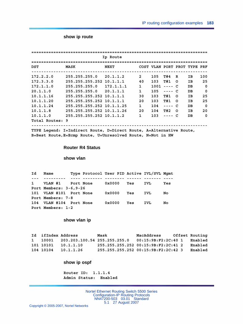
IP routing configuration examples 183
show ip route
========================================================================Ip Route
========================================================================DST MASK NEXT COST VLAN PORT PROT TYPE PRF------------------------------------------------------------------------172.2.2.0 255.255.255.0 20.1.1.2 2 105 T#4 R IB 100172.3.3.0 255.255.255.252 10.1.1.1 40 103 T#1 O IB 25172.1.1.0 255.255.255.0 172.1.1.1 1 1001 ---- C DB 020.1.1.0 255.255.255.0 20.1.1.1 1 105 ---- C DB 010.1.1.16 255.255.255.252 10.1.1.1 30 103 T#1 O IB 2510.1.1.20 255.255.255.252 10.1.1.1 20 103 T#1 O IB 2510.1.1.24 255.255.255.252 10.1.1.25 1 104 ---- C DB 010.1.1.8 255.255.255.252 10.1.1.26 20 104 T#2 O IB 2010.1.1.0 255.255.255.252 10.1.1.2 1 103 ---- C DB 0Total Routes: 9------------------------------------------------------------------------TYPE Legend: I=Indirect Route, D=Direct Route, A=Alternative Route,B=Best Route,E=Ecmp Route, U=Unresolved Route, N=Not in HW
Router R4 Status
show vlan
Id Name Type Protocol User PID Active IVL/SVL Mgmt--- --------- ---- -------- -------- ------ ------- ----1 VLAN #1 Port None 0x0000 Yes IVL YesPort Members: 3-6,9-26101 VLAN #101 Port None 0x0000 Yes IVL NoPort Members: 7-8104 VLAN #104 Port None 0x0000 Yes IVL NoPort Members: 1-2
show vlan ip
Id ifIndex Address Mask MacAddress Offset Routing1 10001 203.203.100.54 255.255.255.0 00:15:9B:F2:2C:40 1 Enabled101 10101 10.1.1.10 255.255.255.252 00:15:9B:F2:2C:41 2 Enabled104 10104 10.1.1.26 255.255.255.252 00:15:9B:F2:2C:42 3 Enabled
show ip ospf
Router ID: 1.1.1.4Admin Status: Enabled
Nortel Ethernet Routing Switch 5500 SeriesConfiguration-IP Routing ProtocolsNN47200-503 03.01 Standard
5.1 27 August 2007Copyright © 2005-2007, Nortel Networks
.
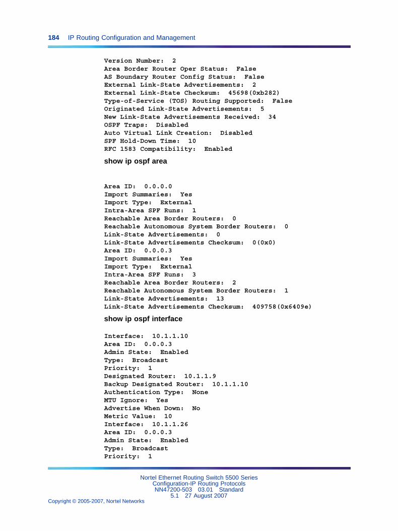
184 IP Routing Configuration and Management
Version Number: 2Area Border Router Oper Status: FalseAS Boundary Router Config Status: FalseExternal Link-State Advertisements: 2External Link-State Checksum: 45698(0xb282)Type-of-Service (TOS) Routing Supported: FalseOriginated Link-State Advertisements: 5New Link-State Advertisements Received: 34OSPF Traps: DisabledAuto Virtual Link Creation: DisabledSPF Hold-Down Time: 10RFC 1583 Compatibility: Enabled
show ip ospf area
Area ID: 0.0.0.0Import Summaries: YesImport Type: ExternalIntra-Area SPF Runs: 1Reachable Area Border Routers: 0Reachable Autonomous System Border Routers: 0Link-State Advertisements: 0Link-State Advertisements Checksum: 0(0x0)Area ID: 0.0.0.3Import Summaries: YesImport Type: ExternalIntra-Area SPF Runs: 3Reachable Area Border Routers: 2Reachable Autonomous System Border Routers: 1Link-State Advertisements: 13Link-State Advertisements Checksum: 409758(0x6409e)
show ip ospf interface
Interface: 10.1.1.10Area ID: 0.0.0.3Admin State: EnabledType: BroadcastPriority: 1Designated Router: 10.1.1.9Backup Designated Router: 10.1.1.10Authentication Type: NoneMTU Ignore: YesAdvertise When Down: NoMetric Value: 10Interface: 10.1.1.26Area ID: 0.0.0.3Admin State: EnabledType: BroadcastPriority: 1
Nortel Ethernet Routing Switch 5500 SeriesConfiguration-IP Routing ProtocolsNN47200-503 03.01 Standard
5.1 27 August 2007Copyright © 2005-2007, Nortel Networks
.
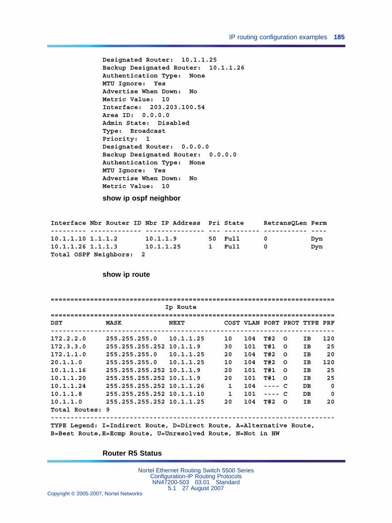
IP routing configuration examples 185
Designated Router: 10.1.1.25Backup Designated Router: 10.1.1.26Authentication Type: NoneMTU Ignore: YesAdvertise When Down: NoMetric Value: 10Interface: 203.203.100.54Area ID: 0.0.0.0Admin State: DisabledType: BroadcastPriority: 1Designated Router: 0.0.0.0Backup Designated Router: 0.0.0.0Authentication Type: NoneMTU Ignore: YesAdvertise When Down: NoMetric Value: 10
show ip ospf neighbor
Interface Nbr Router ID Nbr IP Address Pri State RetransQLen Perm--------- ------------- --------------- --- --------- ----------- ----10.1.1.10 1.1.1.2 10.1.1.9 50 Full 0 Dyn10.1.1.26 1.1.1.3 10.1.1.25 1 Full 0 DynTotal OSPF Neighbors: 2
show ip route
========================================================================Ip Route
========================================================================DST MASK NEXT COST VLAN PORT PROT TYPE PRF------------------------------------------------------------------------172.2.2.0 255.255.255.0 10.1.1.25 10 104 T#2 O IB 120172.3.3.0 255.255.255.252 10.1.1.9 30 101 T#1 O IB 25172.1.1.0 255.255.255.0 10.1.1.25 20 104 T#2 O IB 2020.1.1.0 255.255.255.0 10.1.1.25 10 104 T#2 O IB 12010.1.1.16 255.255.255.252 10.1.1.9 20 101 T#1 O IB 2510.1.1.20 255.255.255.252 10.1.1.9 20 101 T#1 O IB 2510.1.1.24 255.255.255.252 10.1.1.26 1 104 ---- C DB 010.1.1.8 255.255.255.252 10.1.1.10 1 101 ---- C DB 010.1.1.0 255.255.255.252 10.1.1.25 20 104 T#2 O IB 20Total Routes: 9------------------------------------------------------------------------TYPE Legend: I=Indirect Route, D=Direct Route, A=Alternative Route,B=Best Route,E=Ecmp Route, U=Unresolved Route, N=Not in HW
Router R5 Status
Nortel Ethernet Routing Switch 5500 SeriesConfiguration-IP Routing ProtocolsNN47200-503 03.01 Standard
5.1 27 August 2007Copyright © 2005-2007, Nortel Networks
.
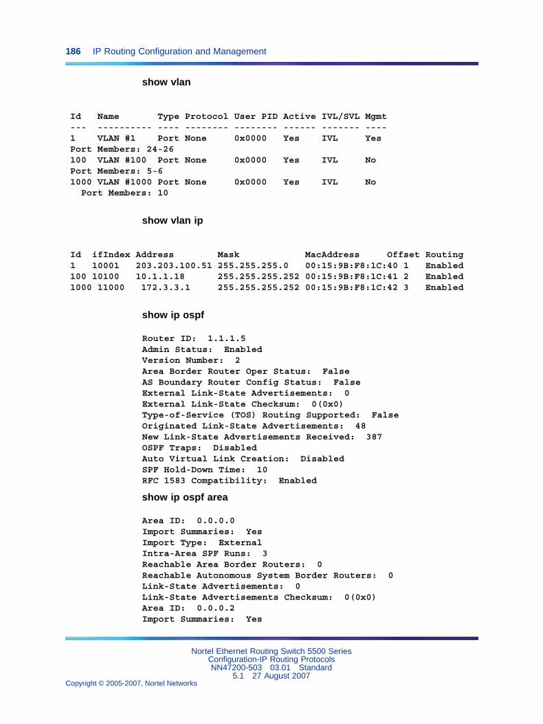
186 IP Routing Configuration and Management
show vlan
Id Name Type Protocol User PID Active IVL/SVL Mgmt--- ---------- ---- -------- -------- ------ ------- ----1 VLAN #1 Port None 0x0000 Yes IVL YesPort Members: 24-26100 VLAN #100 Port None 0x0000 Yes IVL NoPort Members: 5-61000 VLAN #1000 Port None 0x0000 Yes IVL No
Port Members: 10
show vlan ip
Id ifIndex Address Mask MacAddress Offset Routing1 10001 203.203.100.51 255.255.255.0 00:15:9B:F8:1C:40 1 Enabled100 10100 10.1.1.18 255.255.255.252 00:15:9B:F8:1C:41 2 Enabled1000 11000 172.3.3.1 255.255.255.252 00:15:9B:F8:1C:42 3 Enabled
show ip ospf
Router ID: 1.1.1.5Admin Status: EnabledVersion Number: 2Area Border Router Oper Status: FalseAS Boundary Router Config Status: FalseExternal Link-State Advertisements: 0External Link-State Checksum: 0(0x0)Type-of-Service (TOS) Routing Supported: FalseOriginated Link-State Advertisements: 48New Link-State Advertisements Received: 387OSPF Traps: DisabledAuto Virtual Link Creation: DisabledSPF Hold-Down Time: 10RFC 1583 Compatibility: Enabled
show ip ospf area
Area ID: 0.0.0.0Import Summaries: YesImport Type: ExternalIntra-Area SPF Runs: 3Reachable Area Border Routers: 0Reachable Autonomous System Border Routers: 0Link-State Advertisements: 0Link-State Advertisements Checksum: 0(0x0)Area ID: 0.0.0.2Import Summaries: Yes
Nortel Ethernet Routing Switch 5500 SeriesConfiguration-IP Routing ProtocolsNN47200-503 03.01 Standard
5.1 27 August 2007Copyright © 2005-2007, Nortel Networks
.
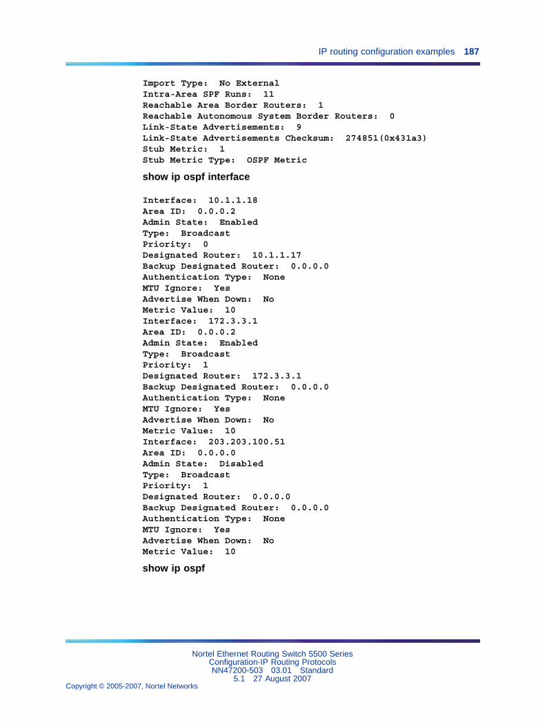
IP routing configuration examples 187
Import Type: No ExternalIntra-Area SPF Runs: 11Reachable Area Border Routers: 1Reachable Autonomous System Border Routers: 0Link-State Advertisements: 9Link-State Advertisements Checksum: 274851(0x431a3)Stub Metric: 1Stub Metric Type: OSPF Metric
show ip ospf interface
Interface: 10.1.1.18Area ID: 0.0.0.2Admin State: EnabledType: BroadcastPriority: 0Designated Router: 10.1.1.17Backup Designated Router: 0.0.0.0Authentication Type: NoneMTU Ignore: YesAdvertise When Down: NoMetric Value: 10Interface: 172.3.3.1Area ID: 0.0.0.2Admin State: EnabledType: BroadcastPriority: 1Designated Router: 172.3.3.1Backup Designated Router: 0.0.0.0Authentication Type: NoneMTU Ignore: YesAdvertise When Down: NoMetric Value: 10Interface: 203.203.100.51Area ID: 0.0.0.0Admin State: DisabledType: BroadcastPriority: 1Designated Router: 0.0.0.0Backup Designated Router: 0.0.0.0Authentication Type: NoneMTU Ignore: YesAdvertise When Down: NoMetric Value: 10
show ip ospf
Nortel Ethernet Routing Switch 5500 SeriesConfiguration-IP Routing ProtocolsNN47200-503 03.01 Standard
5.1 27 August 2007Copyright © 2005-2007, Nortel Networks
.
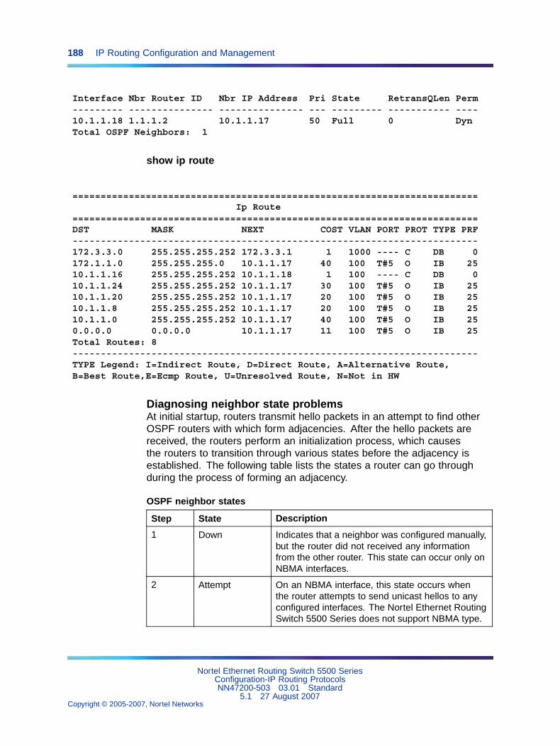
188 IP Routing Configuration and Management
Interface Nbr Router ID Nbr IP Address Pri State RetransQLen Perm--------- --------------- --------------- --- --------- ----------- ----10.1.1.18 1.1.1.2 10.1.1.17 50 Full 0 DynTotal OSPF Neighbors: 1
show ip route
========================================================================Ip Route
========================================================================DST MASK NEXT COST VLAN PORT PROT TYPE PRF------------------------------------------------------------------------172.3.3.0 255.255.255.252 172.3.3.1 1 1000 ---- C DB 0172.1.1.0 255.255.255.0 10.1.1.17 40 100 T#5 O IB 2510.1.1.16 255.255.255.252 10.1.1.18 1 100 ---- C DB 010.1.1.24 255.255.255.252 10.1.1.17 30 100 T#5 O IB 2510.1.1.20 255.255.255.252 10.1.1.17 20 100 T#5 O IB 2510.1.1.8 255.255.255.252 10.1.1.17 20 100 T#5 O IB 2510.1.1.0 255.255.255.252 10.1.1.17 40 100 T#5 O IB 250.0.0.0 0.0.0.0 10.1.1.17 11 100 T#5 O IB 25Total Routes: 8------------------------------------------------------------------------TYPE Legend: I=Indirect Route, D=Direct Route, A=Alternative Route,B=Best Route,E=Ecmp Route, U=Unresolved Route, N=Not in HW
Diagnosing neighbor state problemsAt initial startup, routers transmit hello packets in an attempt to find otherOSPF routers with which form adjacencies. After the hello packets arereceived, the routers perform an initialization process, which causesthe routers to transition through various states before the adjacency isestablished. The following table lists the states a router can go throughduring the process of forming an adjacency.
OSPF neighbor states
Step State Description
1 Down Indicates that a neighbor was configured manually,but the router did not received any informationfrom the other router. This state can occur only onNBMA interfaces.
2 Attempt On an NBMA interface, this state occurs whenthe router attempts to send unicast hellos to anyconfigured interfaces. The Nortel Ethernet RoutingSwitch 5500 Series does not support NBMA type.
Nortel Ethernet Routing Switch 5500 SeriesConfiguration-IP Routing ProtocolsNN47200-503 03.01 Standard
5.1 27 August 2007Copyright © 2005-2007, Nortel Networks
.
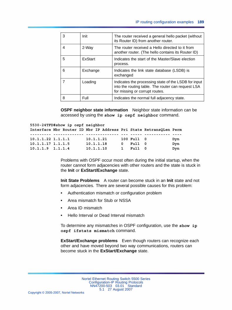
IP routing configuration examples 189
3 Init The router received a general hello packet (withoutits Router ID) from another router.
4 2-Way The router received a Hello directed to it fromanother router. (The hello contains its Router ID)
5 ExStart Indicates the start of the Master/Slave electionprocess.
6 Exchange Indicates the link state database (LSDB) isexchanged
7 Loading Indicates the processing state of the LSDB for inputinto the routing table. The router can request LSAfor missing or corrupt routes.
8 Full Indicates the normal full adjacency state.
OSPF neighbor state information Neighbor state information can beaccessed by using the show ip ospf neighbor command.
5530-24TFD#show ip ospf neighborInterface Nbr Router ID Nbr IP Address Pri State RetransQLen Perm--------- ------------- -------------- --- ----- ----------- ----10.1.1.22 1.1.1.1 10.1.1.21 100 Full 0 Dyn10.1.1.17 1.1.1.5 10.1.1.18 0 Full 0 Dyn10.1.1.9 1.1.1.4 10.1.1.10 1 Full 0 Dyn
Problems with OSPF occur most often during the initial startup, when therouter cannot form adjacencies with other routers and the state is stuck inthe Init or ExStart/Exchange state.
Init State Problems A router can become stuck in an Init state and notform adjacencies. There are several possible causes for this problem:
• Authentication mismatch or configuration problem
• Area mismatch for Stub or NSSA
• Area ID mismatch
• Hello Interval or Dead Interval mismatch
To determine any mismatches in OSPF configuration, use the show ipospf ifstats mismatch command.
ExStart/Exchange problems Even though routers can recognize eachother and have moved beyond two way communications, routers canbecome stuck in the ExStart/Exchange state.
Nortel Ethernet Routing Switch 5500 SeriesConfiguration-IP Routing ProtocolsNN47200-503 03.01 Standard
5.1 27 August 2007Copyright © 2005-2007, Nortel Networks
.
190 IP Routing Configuration and Management
A mismatch in maximum transmission unit (MTU) sizes between the routersusually causes this type of problem. For example, one router could be setfor a high MTU size and the other router a smaller value. Depending on thesize of the link state database, the router with the smaller value may not beable to process the larger packets and thus be stuck in this state. To avoidthis problem, ensure that the MTU size value for both routers match. Thisproblem is usually encountered during interoperations in networks withother vendor devices.
Note: The Nortel Ethernet Routing Switch 5500 Series automaticallychecks for OSPF MTU mismatches.
In the Nortel Ethernet Routing Switch 5500 Series, the supported MTU sizefor OSPF is 1500 bytes by default. Incoming OSPF database description(DBD) packets are dropped if their MTU size is greater than this value.
Virtual Router Redundancy Protocol (VRRP) configurationThis section describes how to create a basic VRRP configuration on aNortel Ethernet Routing Switch 5500 Series.
VRRP uses an election process to select a master router that hosts use asthe default gateway. If the master router (the default gateway) fails, theVRRP backup router automatically replaces the master router and becomesthe new default gateway. In either case, the default gateway IP address andMAC address does not change, thereby providing transparent operation.
The Nortel Ethernet Routing Switch 5500 Series can be configured ina master-master configuration for load-balancing applications that useSplit MultiLink Trunking (SMLT). This configuration allows both switches torespond to ARPs and forward traffic.
VRRP Priority settings can be configured to select the VRRP master routerfor a specified VLAN. The VRRP Priority setting is an integer value, in therange 1 and 255, where the highest value is used to elect the VRRP masterrouter. If two or more switches have the same priority value, the switch withthe highest numerical IP address value is selected and becomes the VRRPmaster. The host is unaware of the entire process.
When a host sends traffic to a different subnet, it sends an ARP request forthe MAC address of the default gateway. In this case, the Nortel EthernetRouting Switch 5500 Series VRRP master router replies with its virtualMAC address. The benefit of using a virtual MAC address is that, if themaster router fails, the VRRP backup router uses the same virtual MACaddress. The virtual MAC address on the Nortel Ethernet Routing Switch5500 Series does not need to be configured. The virtual MAC address isautomatically set as:
Nortel Ethernet Routing Switch 5500 SeriesConfiguration-IP Routing ProtocolsNN47200-503 03.01 Standard
5.1 27 August 2007Copyright © 2005-2007, Nortel Networks
.
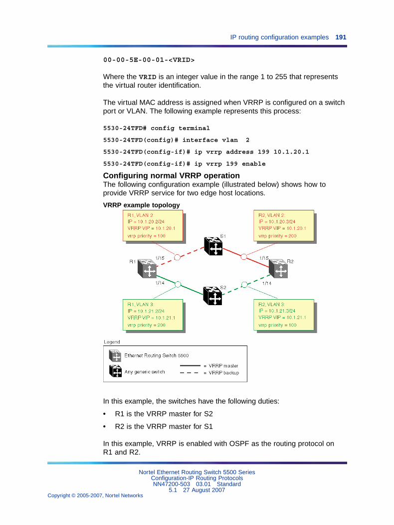
IP routing configuration examples 191
00-00-5E-00-01-<VRID>
Where the VRID is an integer value in the range 1 to 255 that representsthe virtual router identification.
The virtual MAC address is assigned when VRRP is configured on a switchport or VLAN. The following example represents this process:
5530-24TFD# config terminal
5530-24TFD(config)# interface vlan 2
5530-24TFD(config-if)# ip vrrp address 199 10.1.20.1
5530-24TFD(config-if)# ip vrrp 199 enable
Configuring normal VRRP operationThe following configuration example (illustrated below) shows how toprovide VRRP service for two edge host locations.
VRRP example topology
In this example, the switches have the following duties:
• R1 is the VRRP master for S2
• R2 is the VRRP master for S1
In this example, VRRP is enabled with OSPF as the routing protocol onR1 and R2.
Nortel Ethernet Routing Switch 5500 SeriesConfiguration-IP Routing ProtocolsNN47200-503 03.01 Standard
5.1 27 August 2007Copyright © 2005-2007, Nortel Networks
.
192 IP Routing Configuration and Management
The VRRP priority setting is used to determine which router will becomethe VRRP master and which will become the VRRP backup. In instanceswhere the priority setting is the same for two routers, the higher IP addressbecomes the tie breaker. Therefore, it is very important to set the correctVRRP priority. VRRP fast advertisement will also be enabled in this exampleto allow for fast failover detection.
The following procedure outlines the steps necessary to reproduce theexample described above:
Step Action
1 Configure VLAN 2 on router R1.
a. Create VLAN 2 on router R1.
5530-24TFD# config terminal5530-24TFD(config)# vlan create 2 type port
b. Configure the ports for VLAN 2 on R1.
5530-24TFD# config terminal5530-24TFD(config)# vlan members add 2 1/15
c. Configure an IP address for VLAN 2.
Add IP address 10.1.20.2 / 255.255.255.0 to VLAN 2.
5530-24TFD# config terminal5530-24TFD(config)# interface vlan 25530-24TFD(config-if)# ip address 10.1.20.2255.255.255.0
d. Configure an OSPF interface for VLAN 2.
5530-24TFD# config terminal5530-24TFD(config)# router ospf enable5530-24TFD(config)# router ospf5530-24TFD(config-router)# network 10.1.20.2
e. Configure VRRP on VLAN 2.
The VRRP VIP address of 10.1.20.1 is added to VLAN 2 usinga VRID of 1.
Note 1: The VRRP priority is not configured here; it is left atfactory default of 100. Instead, the priority setting on routerR2 will be set to a higher value when R2 is configured.
Note 2: Fast advertisement is disabled by default. Fastadvertisement is proprietary to Nortel to support anadvertisement interval from 200 to 1000 milliseconds (ms)with a default of 200. If fast VRRP advertisement is desired,enable fast advertisement.
Nortel Ethernet Routing Switch 5500 SeriesConfiguration-IP Routing ProtocolsNN47200-503 03.01 Standard
5.1 27 August 2007Copyright © 2005-2007, Nortel Networks
.
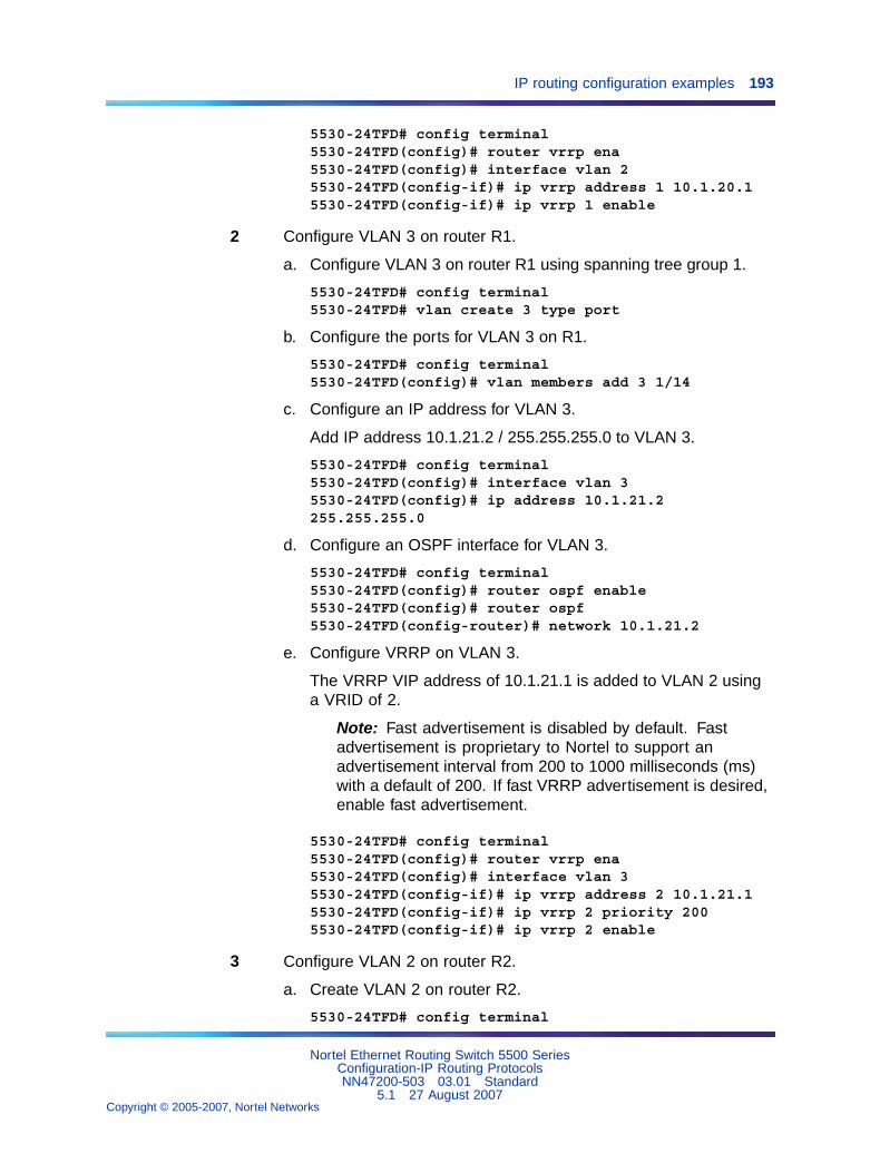
IP routing configuration examples 193
5530-24TFD# config terminal5530-24TFD(config)# router vrrp ena5530-24TFD(config)# interface vlan 25530-24TFD(config-if)# ip vrrp address 1 10.1.20.15530-24TFD(config-if)# ip vrrp 1 enable
2 Configure VLAN 3 on router R1.
a. Configure VLAN 3 on router R1 using spanning tree group 1.
5530-24TFD# config terminal5530-24TFD# vlan create 3 type port
b. Configure the ports for VLAN 3 on R1.
5530-24TFD# config terminal5530-24TFD(config)# vlan members add 3 1/14
c. Configure an IP address for VLAN 3.
Add IP address 10.1.21.2 / 255.255.255.0 to VLAN 3.
5530-24TFD# config terminal5530-24TFD(config)# interface vlan 35530-24TFD(config)# ip address 10.1.21.2255.255.255.0
d. Configure an OSPF interface for VLAN 3.
5530-24TFD# config terminal5530-24TFD(config)# router ospf enable5530-24TFD(config)# router ospf5530-24TFD(config-router)# network 10.1.21.2
e. Configure VRRP on VLAN 3.
The VRRP VIP address of 10.1.21.1 is added to VLAN 2 usinga VRID of 2.
Note: Fast advertisement is disabled by default. Fastadvertisement is proprietary to Nortel to support anadvertisement interval from 200 to 1000 milliseconds (ms)with a default of 200. If fast VRRP advertisement is desired,enable fast advertisement.
5530-24TFD# config terminal5530-24TFD(config)# router vrrp ena5530-24TFD(config)# interface vlan 35530-24TFD(config-if)# ip vrrp address 2 10.1.21.15530-24TFD(config-if)# ip vrrp 2 priority 2005530-24TFD(config-if)# ip vrrp 2 enable
3 Configure VLAN 2 on router R2.
a. Create VLAN 2 on router R2.
5530-24TFD# config terminal
Nortel Ethernet Routing Switch 5500 SeriesConfiguration-IP Routing ProtocolsNN47200-503 03.01 Standard
5.1 27 August 2007Copyright © 2005-2007, Nortel Networks
.
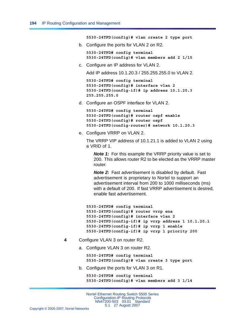
194 IP Routing Configuration and Management
5530-24TFD(config)# vlan create 2 type port
b. Configure the ports for VLAN 2 on R2.
5530-24TFD# config terminal5530-24TFD(config)# vlan members add 2 1/15
c. Configure an IP address for VLAN 2.
Add IP address 10.1.20.3 / 255.255.255.0 to VLAN 2.
5530-24TFD# config terminal5530-24TFD(config)# interface vlan 25530-24TFD(config-if)# ip address 10.1.20.3255.255.255.0
d. Configure an OSPF interface for VLAN 2.
5530-24TFD# config terminal5530-24TFD(config)# router ospf enable5530-24TFD(config)# router ospf5530-24TFD(config-router)# network 10.1.20.3
e. Configure VRRP on VLAN 2.
The VRRP VIP address of 10.1.21.1 is added to VLAN 2 usinga VRID of 1.
Note 1: For this example the VRRP priority value is set to200. This allows router R2 to be elected as the VRRP masterrouter.
Note 2: Fast advertisement is disabled by default. Fastadvertisement is proprietary to Nortel to support anadvertisement interval from 200 to 1000 milliseconds (ms)with a default of 200. If fast VRRP advertisement is desired,enable fast advertisement.
5530-24TFD# config terminal5530-24TFD(config)# router vrrp ena5530-24TFD(config)# interface vlan 25530-24TFD(config-if)# ip vrrp address 1 10.1.20.15530-24TFD(config-if)# ip vrrp 1 enable5530-24TFD(config-if)# ip vrrp 1 priority 200
4 Configure VLAN 3 on router R2.
a. Configure VLAN 3 on router R2.
5530-24TFD# config terminal5530-24TFD(config)# vlan create 3 type port
b. Configure the ports for VLAN 3 on R1.
5530-24TFD# config terminal5530-24TFD(config)# vlan members add 3 1/14
Nortel Ethernet Routing Switch 5500 SeriesConfiguration-IP Routing ProtocolsNN47200-503 03.01 Standard
5.1 27 August 2007Copyright © 2005-2007, Nortel Networks
.
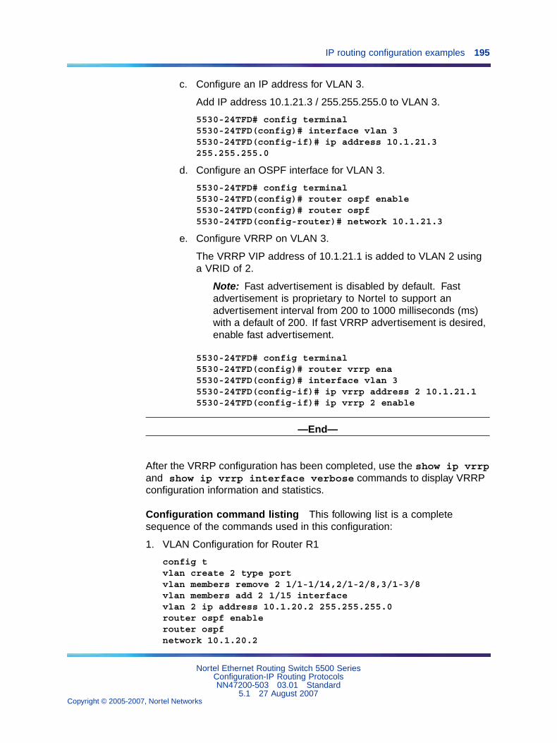
IP routing configuration examples 195
c. Configure an IP address for VLAN 3.
Add IP address 10.1.21.3 / 255.255.255.0 to VLAN 3.
5530-24TFD# config terminal5530-24TFD(config)# interface vlan 35530-24TFD(config-if)# ip address 10.1.21.3255.255.255.0
d. Configure an OSPF interface for VLAN 3.
5530-24TFD# config terminal5530-24TFD(config)# router ospf enable5530-24TFD(config)# router ospf5530-24TFD(config-router)# network 10.1.21.3
e. Configure VRRP on VLAN 3.
The VRRP VIP address of 10.1.21.1 is added to VLAN 2 usinga VRID of 2.
Note: Fast advertisement is disabled by default. Fastadvertisement is proprietary to Nortel to support anadvertisement interval from 200 to 1000 milliseconds (ms)with a default of 200. If fast VRRP advertisement is desired,enable fast advertisement.
5530-24TFD# config terminal5530-24TFD(config)# router vrrp ena5530-24TFD(config)# interface vlan 35530-24TFD(config-if)# ip vrrp address 2 10.1.21.15530-24TFD(config-if)# ip vrrp 2 enable
—End—
After the VRRP configuration has been completed, use the show ip vrrpand show ip vrrp interface verbose commands to display VRRPconfiguration information and statistics.
Configuration command listing This following list is a completesequence of the commands used in this configuration:
1. VLAN Configuration for Router R1
config tvlan create 2 type portvlan members remove 2 1/1-1/14,2/1-2/8,3/1-3/8vlan members add 2 1/15 interfacevlan 2 ip address 10.1.20.2 255.255.255.0router ospf enablerouter ospfnetwork 10.1.20.2
Nortel Ethernet Routing Switch 5500 SeriesConfiguration-IP Routing ProtocolsNN47200-503 03.01 Standard
5.1 27 August 2007Copyright © 2005-2007, Nortel Networks
.

196 IP Routing Configuration and Management
router vrrp enainterface vlan 2ip vrrp address 1 10.1.20.1ip vrrp 1 enablevlan create 3 type portinterface vlan 3ip address 10.1.21.2 255.255.255.0router ospf enablerouter ospfnetwork 10.1.21.2router vrrp enainterface vlan 3ip vrrp address 2 10.1.21.1ip vrrp 2 priority 200ip vrrp 2 enable
2. VLAN Configuration for Router R2
config tvlan create 2 type portvlan members remove 2 1/1-1/14,2/1-2/8,3/1-3/8vlan members add 2 1/15 interface vlan 2ip address 10.1.20.3 255.255.255.0router ospf enablerouter ospfnetwork 10.1.20.3router vrrp enainterface vlan 2ip vrrp address 1 10.1.20.1ip vrrp 1 priority 200ip vrrp 1 enablevlan create 3 type portvlan members remove 3 1/1-1/14,1/15,2/1-2/8,3/1-3/8vlan members add 3 1/14interface vlan 3ip address 10.1.21.3 255.255.255.0router ospf enablerouter ospfnetwork 10.1.21.3router vrrp enainterface vlan 3ip vrrp address 2 10.1.21.1ip vrrp 2 enable
Configuring VRRP with SMLTThis configuration example shows how you can provide high availability fora Layer 2 edge switch feeding into a Layer 3 core. As demonstrated below,both R1 and R2 switches are configured with a port-based VLAN (VLAN2) with SMLT and VRRP set to enabled. This topology provides failoverprotection and load-balancing.
Nortel Ethernet Routing Switch 5500 SeriesConfiguration-IP Routing ProtocolsNN47200-503 03.01 Standard
5.1 27 August 2007Copyright © 2005-2007, Nortel Networks
.
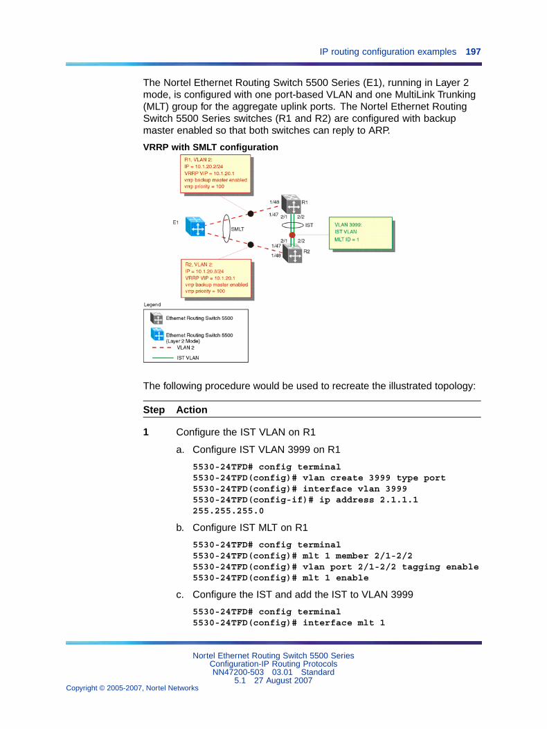
IP routing configuration examples 197
The Nortel Ethernet Routing Switch 5500 Series (E1), running in Layer 2mode, is configured with one port-based VLAN and one MultiLink Trunking(MLT) group for the aggregate uplink ports. The Nortel Ethernet RoutingSwitch 5500 Series switches (R1 and R2) are configured with backupmaster enabled so that both switches can reply to ARP.
VRRP with SMLT configuration
The following procedure would be used to recreate the illustrated topology:
Step Action
1 Configure the IST VLAN on R1
a. Configure IST VLAN 3999 on R1
5530-24TFD# config terminal5530-24TFD(config)# vlan create 3999 type port5530-24TFD(config)# interface vlan 39995530-24TFD(config-if)# ip address 2.1.1.1255.255.255.0
b. Configure IST MLT on R1
5530-24TFD# config terminal5530-24TFD(config)# mlt 1 member 2/1-2/25530-24TFD(config)# vlan port 2/1-2/2 tagging enable5530-24TFD(config)# mlt 1 enable
c. Configure the IST and add the IST to VLAN 3999
5530-24TFD# config terminal5530-24TFD(config)# interface mlt 1
Nortel Ethernet Routing Switch 5500 SeriesConfiguration-IP Routing ProtocolsNN47200-503 03.01 Standard
5.1 27 August 2007Copyright © 2005-2007, Nortel Networks
.
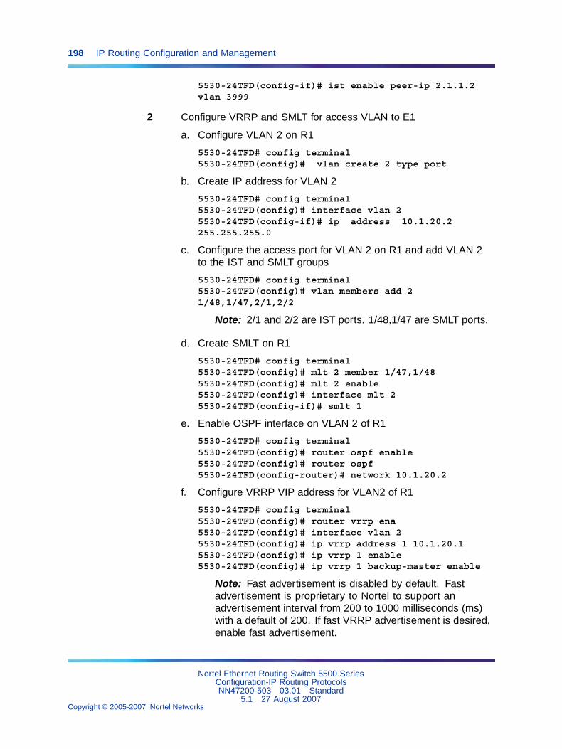
198 IP Routing Configuration and Management
5530-24TFD(config-if)# ist enable peer-ip 2.1.1.2vlan 3999
2 Configure VRRP and SMLT for access VLAN to E1
a. Configure VLAN 2 on R1
5530-24TFD# config terminal5530-24TFD(config)# vlan create 2 type port
b. Create IP address for VLAN 2
5530-24TFD# config terminal5530-24TFD(config)# interface vlan 25530-24TFD(config-if)# ip address 10.1.20.2255.255.255.0
c. Configure the access port for VLAN 2 on R1 and add VLAN 2to the IST and SMLT groups
5530-24TFD# config terminal5530-24TFD(config)# vlan members add 21/48,1/47,2/1,2/2
Note: 2/1 and 2/2 are IST ports. 1/48,1/47 are SMLT ports.
d. Create SMLT on R1
5530-24TFD# config terminal5530-24TFD(config)# mlt 2 member 1/47,1/485530-24TFD(config)# mlt 2 enable5530-24TFD(config)# interface mlt 25530-24TFD(config-if)# smlt 1
e. Enable OSPF interface on VLAN 2 of R1
5530-24TFD# config terminal5530-24TFD(config)# router ospf enable5530-24TFD(config)# router ospf5530-24TFD(config-router)# network 10.1.20.2
f. Configure VRRP VIP address for VLAN2 of R1
5530-24TFD# config terminal5530-24TFD(config)# router vrrp ena5530-24TFD(config)# interface vlan 25530-24TFD(config)# ip vrrp address 1 10.1.20.15530-24TFD(config)# ip vrrp 1 enable5530-24TFD(config)# ip vrrp 1 backup-master enable
Note: Fast advertisement is disabled by default. Fastadvertisement is proprietary to Nortel to support anadvertisement interval from 200 to 1000 milliseconds (ms)with a default of 200. If fast VRRP advertisement is desired,enable fast advertisement.
Nortel Ethernet Routing Switch 5500 SeriesConfiguration-IP Routing ProtocolsNN47200-503 03.01 Standard
5.1 27 August 2007Copyright © 2005-2007, Nortel Networks
.
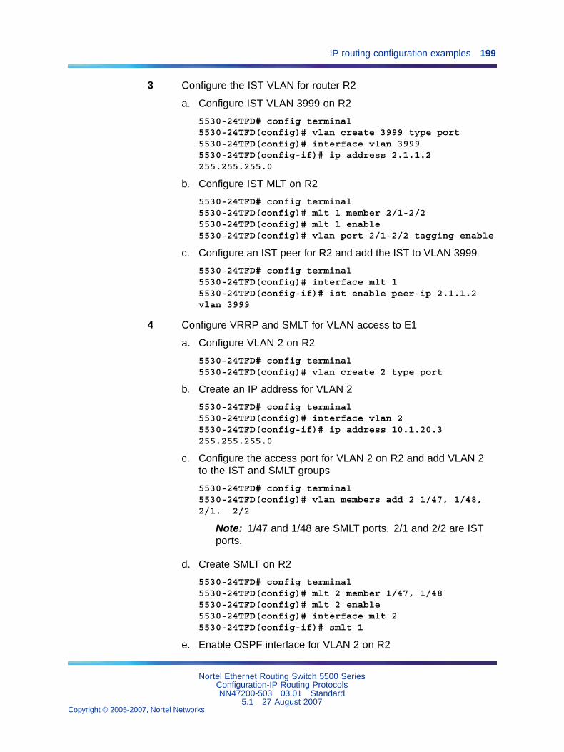
IP routing configuration examples 199
3 Configure the IST VLAN for router R2
a. Configure IST VLAN 3999 on R2
5530-24TFD# config terminal5530-24TFD(config)# vlan create 3999 type port5530-24TFD(config)# interface vlan 39995530-24TFD(config-if)# ip address 2.1.1.2255.255.255.0
b. Configure IST MLT on R2
5530-24TFD# config terminal5530-24TFD(config)# mlt 1 member 2/1-2/25530-24TFD(config)# mlt 1 enable5530-24TFD(config)# vlan port 2/1-2/2 tagging enable
c. Configure an IST peer for R2 and add the IST to VLAN 3999
5530-24TFD# config terminal5530-24TFD(config)# interface mlt 15530-24TFD(config-if)# ist enable peer-ip 2.1.1.2vlan 3999
4 Configure VRRP and SMLT for VLAN access to E1
a. Configure VLAN 2 on R2
5530-24TFD# config terminal5530-24TFD(config)# vlan create 2 type port
b. Create an IP address for VLAN 2
5530-24TFD# config terminal5530-24TFD(config)# interface vlan 25530-24TFD(config-if)# ip address 10.1.20.3255.255.255.0
c. Configure the access port for VLAN 2 on R2 and add VLAN 2to the IST and SMLT groups
5530-24TFD# config terminal5530-24TFD(config)# vlan members add 2 1/47, 1/48,2/1. 2/2
Note: 1/47 and 1/48 are SMLT ports. 2/1 and 2/2 are ISTports.
d. Create SMLT on R2
5530-24TFD# config terminal5530-24TFD(config)# mlt 2 member 1/47, 1/485530-24TFD(config)# mlt 2 enable5530-24TFD(config)# interface mlt 25530-24TFD(config-if)# smlt 1
e. Enable OSPF interface for VLAN 2 on R2
Nortel Ethernet Routing Switch 5500 SeriesConfiguration-IP Routing ProtocolsNN47200-503 03.01 Standard
5.1 27 August 2007Copyright © 2005-2007, Nortel Networks
.
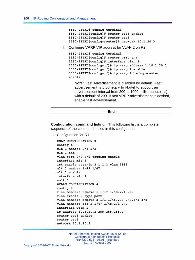
200 IP Routing Configuration and Management
5530-24TFD# config terminal5530-24TFD(config)# router ospf enable5530-24TFD(config)# router ospf5530-24TFD(config-router)# network 10.1.20.3
f. Configure VRRP VIP address for VLAN 2 on R2
5530-24TFD# config terminal5530-24TFD(config)# router vrrp ena5530-24TFD(config)# interface vlan 25530-24TFD(config-if)# ip vrrp address 1 10.1.20.15530-24TFD(config-if)# ip vrrp 1 enable5530-24TFD(config-if)# ip vrrp 1 backup-masterenable
Note: Fast Advertisement is disabled by default. Fastadvertisement is proprietary to Nortel to support anadvertisement interval from 200 to 1000 milliseconds (ms)with a default of 200. If fast VRRP advertisement is desired,enable fast advertisement.
—End—
Configuration command listing This following list is a completesequence of the commands used in this configuration:
1. Configuration for R1
#MLT CONFIGURATION #config tmlt 1 member 2/1-2/2mlt 1 enavlan port 2/2-2/2 tagging enableinterface mlt 1ist enable peer-ip 2.1.1.2 vlan 3999mlt 2 member 1/48,1/47mlt 2 enableinterface mlt 2smlt 1#VLAN CONFIGURATION #config tvlan members remove 1 1/47-1/48,2/1-2/2vlan create 2 type portvlan members remove 2 1/1-1/46,2/3-2/8,3/1-3/8vlan members add 2 1/47-1/48,2/1-2/2interface vlan 2ip address 10.1.20.2 255.255.255.0router ospf enablerouter ospfnetwork 10.1.20.2
Nortel Ethernet Routing Switch 5500 SeriesConfiguration-IP Routing ProtocolsNN47200-503 03.01 Standard
5.1 27 August 2007Copyright © 2005-2007, Nortel Networks
.
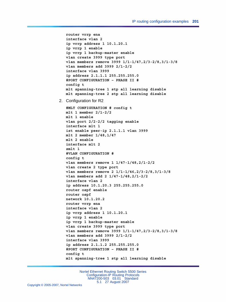
IP routing configuration examples 201
router vrrp enainterface vlan 2ip vrrp address 1 10.1.20.1ip vrrp 1 enableip vrrp 1 backup-master enablevlan create 3999 type portvlan members remove 3999 1/1-1/47,2/3-2/8,3/1-3/8vlan members add 3999 2/1-2/2interface vlan 3999ip address 2.1.1.1 255.255.255.0#PORT CONFIGURATION – PHASE II #config tmlt spanning-tree 1 stp all learning disablemlt spanning-tree 2 stp all learning disable
2. Configuration for R2
#MLT CONFIGURATION # config tmlt 1 member 2/1-2/2mlt 1 enablevlan port 2/2-2/2 tagging enableinterface mlt 1ist enable peer-ip 2.1.1.1 vlan 3999mlt 2 member 1/48,1/47mlt 2 enableinterface mlt 2smlt 1#VLAN CONFIGURATION #config tvlan members remove 1 1/47-1/48,2/1-2/2vlan create 2 type portvlan members remove 2 1/1-1/46,2/3-2/8,3/1-3/8vlan members add 2 1/47-1/48,2/1-2/2interface vlan 2ip address 10.1.20.3 255.255.255.0router ospf enablerouter ospfnetwork 10.1.20.2router vrrp enainterface vlan 2ip vrrp address 1 10.1.20.1ip vrrp 1 enableip vrrp 1 backup-master enablevlan create 3999 type portvlan members remove 3999 1/1-1/47,2/3-2/8,3/1-3/8vlan members add 3999 2/1-2/2interface vlan 3999ip address 2.1.1.2 255.255.255.0#PORT CONFIGURATION – PHASE II #config tmlt spanning-tree 1 stp all learning disable
Nortel Ethernet Routing Switch 5500 SeriesConfiguration-IP Routing ProtocolsNN47200-503 03.01 Standard
5.1 27 August 2007Copyright © 2005-2007, Nortel Networks
.
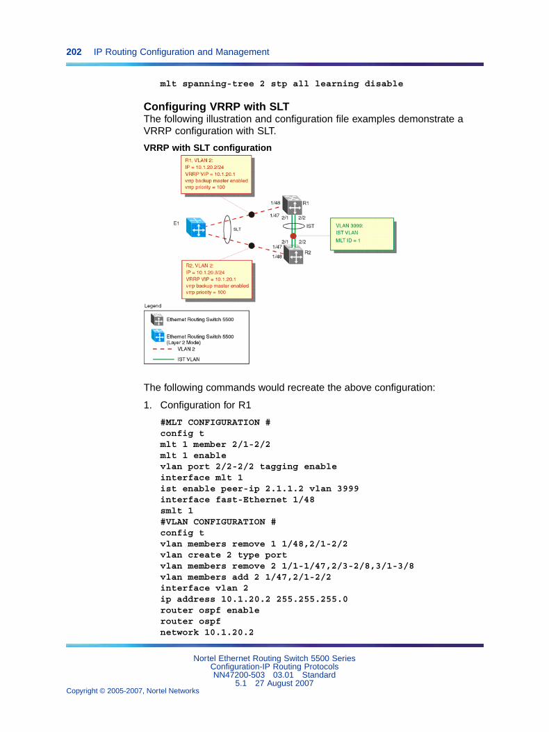
202 IP Routing Configuration and Management
mlt spanning-tree 2 stp all learning disable
Configuring VRRP with SLTThe following illustration and configuration file examples demonstrate aVRRP configuration with SLT.
VRRP with SLT configuration
The following commands would recreate the above configuration:
1. Configuration for R1
#MLT CONFIGURATION #config tmlt 1 member 2/1-2/2mlt 1 enablevlan port 2/2-2/2 tagging enableinterface mlt 1ist enable peer-ip 2.1.1.2 vlan 3999interface fast-Ethernet 1/48smlt 1#VLAN CONFIGURATION #config tvlan members remove 1 1/48,2/1-2/2vlan create 2 type portvlan members remove 2 1/1-1/47,2/3-2/8,3/1-3/8vlan members add 2 1/47,2/1-2/2interface vlan 2ip address 10.1.20.2 255.255.255.0router ospf enablerouter ospfnetwork 10.1.20.2
Nortel Ethernet Routing Switch 5500 SeriesConfiguration-IP Routing ProtocolsNN47200-503 03.01 Standard
5.1 27 August 2007Copyright © 2005-2007, Nortel Networks
.
IP routing configuration examples 203
router vrrp enainterface vlan 2ip vrrp address 1 10.1.20.1ip vrrp 1 enableip vrrp 1 backup-master enablevlan create 3999 type portvlan members remove 3999 1/1-1/47,2/3-2/8,3/1-3/8vlan members add 3999 2/1-2/2interface vlan 3999ip address 2.1.1.1 255.255.255.0#PORT CONFIGURATION – PHASE II #config tmlt spanning-tree 1 stp all learning disableinterface fast-Ethernet 1/48spanning-tree stp 1 learning disable
2. Configuration for R2
#MLT CONFIGURATION #config tmlt 1 member 2/1-2/2mlt 1 enablevlan port 2/2-2/2 tagging enableinterface mlt 1ist enable peer-ip 2.1.1.1 vlan 3999interface fast-Ethernet 1/48smlt 1#VLAN CONFIGURATION #config tvlan members remove 1 1/48,2/1-2/2vlan create 2 type portvlan members remove 2 1/1-1/47,2/3-2/8,3/1-3/8vlan members add 2 1/48,2/1-2/2interface vlan 2ip address 10.1.20.3 255.255.255.0router ospf enablerouter ospfnetwork 10.1.20.2router vrrp enainterface vlan 2ip vrrp address 1 10.1.20.1ip vrrp 1 enableip vrrp 1 backup-master enablevlan create 3999 type portvlan members remove 3999 1/1-1/47,2/3-2/8,3/1-3/8vlan members add 3999 2/1-2/2interface vlan 3999ip address 2.1.1.2 255.255.255.0#PORT CONFIGURATION – PHASE II #config tmlt spanning-tree 1 stp all learning disable
Nortel Ethernet Routing Switch 5500 SeriesConfiguration-IP Routing ProtocolsNN47200-503 03.01 Standard
5.1 27 August 2007Copyright © 2005-2007, Nortel Networks
.
204 IP Routing Configuration and Management
interface fast-Ethernet 1/48spanning-tree stp 1 learning disable
Equal Cost Multipath (ECMP)Equal Cost Multipath (ECMP) is an IP feature for load-balancing routed IPtraffic across up to four equal-cost paths for each supported protocol. ECMPsupports OSPF, RIP, and static routes. Some benefits of using ECMP:
• Supported protocols will rerun when an ECMP path fails, and the otherconfigured paths will automatically take the load.
• Load sharing implies better use of network facilities.
ECMP is selected based on the source and destination IP address in thepacket. The hash_control register has a HASH_SELECT field which is setto 5 (lower CRC-32).
R1 = CRC32 (SIP, DIP)
R2 = R1 & 0x1F(The Least Significant 5 bits are selected)
ecmp_index = R2 % (ecmp_count + 1)
Note: The value ecmp_count above is zero-based in the hardware soif four paths are present then the value is three. This is why the valueis ecmp_count + 1.
The ECMP traffic distribution algorithm is demonstrated in the followingexample:
Consider two network devices, Device 1 at the IP address 192.1.1.3 andDevice 2 at 192.1.1.4. Device 1 send to Device 2 so that 192.1.1.3 is thesource IP address (SIP) and 192.1.1.4 is the destination IP address (Device2).
To calculate the CRC32 for the example source and destination IP addressnoted above, the following calculations would be made:
• CRC32 polynomial : x ^ 32 + x ^ 28 + x ^ 23 + x ^ 22 + x ^ 16 + x ^ 12 +x ^ 11 + x ^ 10 + x ^ 8 + x ^ 7 + x ^ 5 + x ^ 4 + x ^ 2 + x ^ 1 + 1
• R1 = CRC32 ( 0xc0010103, 0xc0010104 ) = 0xf474b549
• R2 = ( 0xf474b549 & 0x1f ) = 9
If, for the purposes of this example, it is assumed that the ECMP count is 4(hardware entries 0 though 3), the following calculation is then made:
• ecmp_index = 9 % ( 4+1 ) = 1
This means that in this example, the second path at hardware index 1 inthe ECMP table will be used.
Nortel Ethernet Routing Switch 5500 SeriesConfiguration-IP Routing ProtocolsNN47200-503 03.01 Standard
5.1 27 August 2007Copyright © 2005-2007, Nortel Networks
.
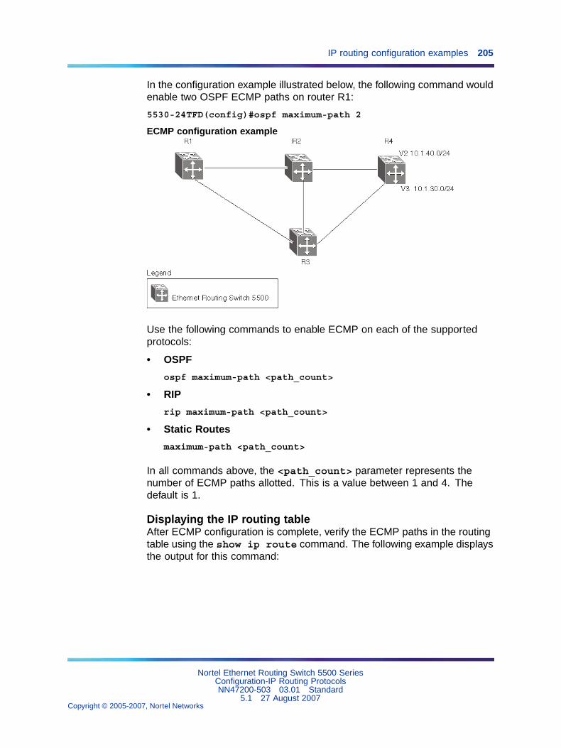
IP routing configuration examples 205
In the configuration example illustrated below, the following command wouldenable two OSPF ECMP paths on router R1:
5530-24TFD(config)#ospf maximum-path 2
ECMP configuration example
Use the following commands to enable ECMP on each of the supportedprotocols:
• OSPF
ospf maximum-path <path_count>
• RIP
rip maximum-path <path_count>
• Static Routes
maximum-path <path_count>
In all commands above, the <path_count> parameter represents thenumber of ECMP paths allotted. This is a value between 1 and 4. Thedefault is 1.
Displaying the IP routing tableAfter ECMP configuration is complete, verify the ECMP paths in the routingtable using the show ip route command. The following example displaysthe output for this command:
Nortel Ethernet Routing Switch 5500 SeriesConfiguration-IP Routing ProtocolsNN47200-503 03.01 Standard
5.1 27 August 2007Copyright © 2005-2007, Nortel Networks
.
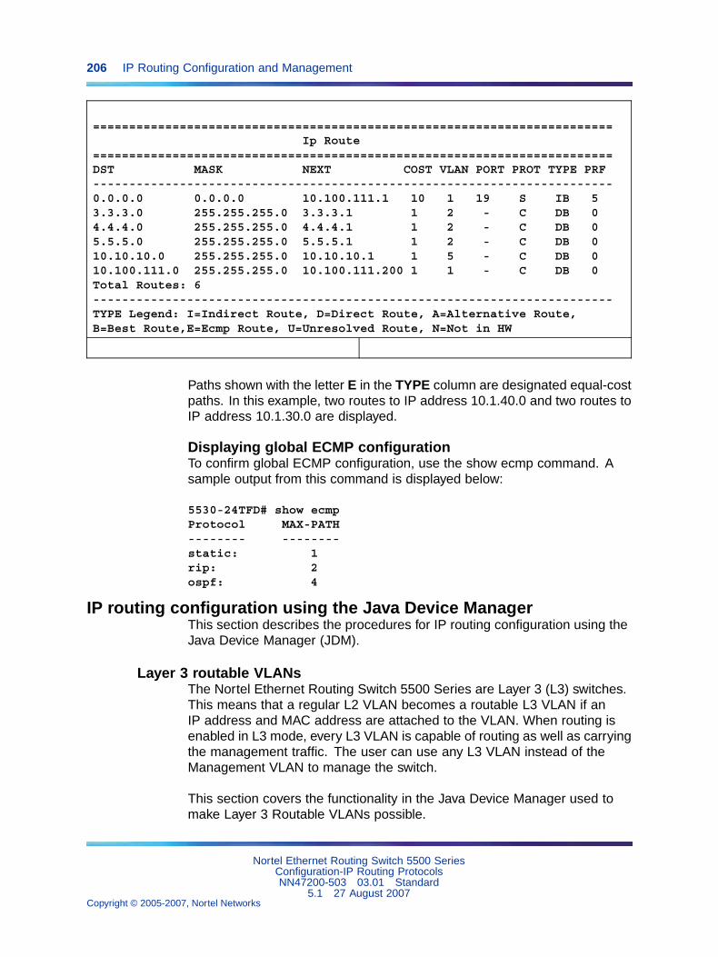
206 IP Routing Configuration and Management
========================================================================Ip Route
========================================================================DST MASK NEXT COST VLAN PORT PROT TYPE PRF------------------------------------------------------------------------0.0.0.0 0.0.0.0 10.100.111.1 10 1 19 S IB 53.3.3.0 255.255.255.0 3.3.3.1 1 2 - C DB 04.4.4.0 255.255.255.0 4.4.4.1 1 2 - C DB 05.5.5.0 255.255.255.0 5.5.5.1 1 2 - C DB 010.10.10.0 255.255.255.0 10.10.10.1 1 5 - C DB 010.100.111.0 255.255.255.0 10.100.111.200 1 1 - C DB 0Total Routes: 6------------------------------------------------------------------------TYPE Legend: I=Indirect Route, D=Direct Route, A=Alternative Route,B=Best Route,E=Ecmp Route, U=Unresolved Route, N=Not in HW
Paths shown with the letter E in the TYPE column are designated equal-costpaths. In this example, two routes to IP address 10.1.40.0 and two routes toIP address 10.1.30.0 are displayed.
Displaying global ECMP configurationTo confirm global ECMP configuration, use the show ecmp command. Asample output from this command is displayed below:
5530-24TFD# show ecmpProtocol MAX-PATH-------- --------static: 1rip: 2ospf: 4
IP routing configuration using the Java Device ManagerThis section describes the procedures for IP routing configuration using theJava Device Manager (JDM).
Layer 3 routable VLANsThe Nortel Ethernet Routing Switch 5500 Series are Layer 3 (L3) switches.This means that a regular L2 VLAN becomes a routable L3 VLAN if anIP address and MAC address are attached to the VLAN. When routing isenabled in L3 mode, every L3 VLAN is capable of routing as well as carryingthe management traffic. The user can use any L3 VLAN instead of theManagement VLAN to manage the switch.
This section covers the functionality in the Java Device Manager used tomake Layer 3 Routable VLANs possible.
Nortel Ethernet Routing Switch 5500 SeriesConfiguration-IP Routing ProtocolsNN47200-503 03.01 Standard
5.1 27 August 2007Copyright © 2005-2007, Nortel Networks
.
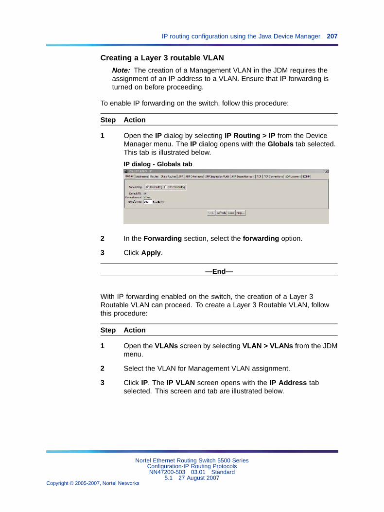
IP routing configuration using the Java Device Manager 207
Creating a Layer 3 routable VLAN
Note: The creation of a Management VLAN in the JDM requires theassignment of an IP address to a VLAN. Ensure that IP forwarding isturned on before proceeding.
To enable IP forwarding on the switch, follow this procedure:
Step Action
1 Open the IP dialog by selecting IP Routing > IP from the DeviceManager menu. The IP dialog opens with the Globals tab selected.This tab is illustrated below.
IP dialog - Globals tab
2 In the Forwarding section, select the forwarding option.
3 Click Apply.
—End—
With IP forwarding enabled on the switch, the creation of a Layer 3Routable VLAN can proceed. To create a Layer 3 Routable VLAN, followthis procedure:
Step Action
1 Open the VLANs screen by selecting VLAN > VLANs from the JDMmenu.
2 Select the VLAN for Management VLAN assignment.
3 Click IP. The IP VLAN screen opens with the IP Address tabselected. This screen and tab are illustrated below.
Nortel Ethernet Routing Switch 5500 SeriesConfiguration-IP Routing ProtocolsNN47200-503 03.01 Standard
5.1 27 August 2007Copyright © 2005-2007, Nortel Networks
.
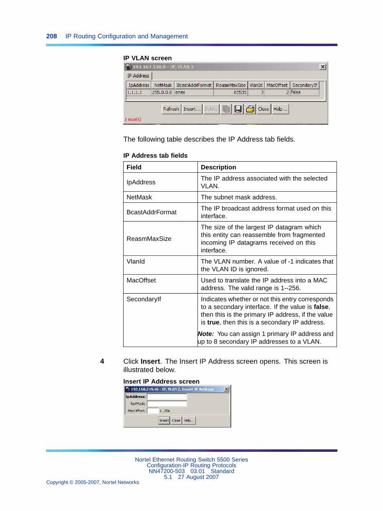
208 IP Routing Configuration and Management
IP VLAN screen
The following table describes the IP Address tab fields.
IP Address tab fields
Field Description
IpAddressThe IP address associated with the selectedVLAN.
NetMask The subnet mask address.
BcastAddrFormatThe IP broadcast address format used on thisinterface.
ReasmMaxSize
The size of the largest IP datagram whichthis entity can reassemble from fragmentedincoming IP datagrams received on thisinterface.
VlanId The VLAN number. A value of -1 indicates thatthe VLAN ID is ignored.
MacOffset Used to translate the IP address into a MACaddress. The valid range is 1--256.
SecondaryIf Indicates whether or not this entry correspondsto a secondary interface. If the value is false,then this is the primary IP address, if the valueis true, then this is a secondary IP address.
Note: You can assign 1 primary IP address andup to 8 secondary IP addresses to a VLAN.
4 Click Insert. The Insert IP Address screen opens. This screen isillustrated below.
Insert IP Address screen
Nortel Ethernet Routing Switch 5500 SeriesConfiguration-IP Routing ProtocolsNN47200-503 03.01 Standard
5.1 27 August 2007Copyright © 2005-2007, Nortel Networks
.
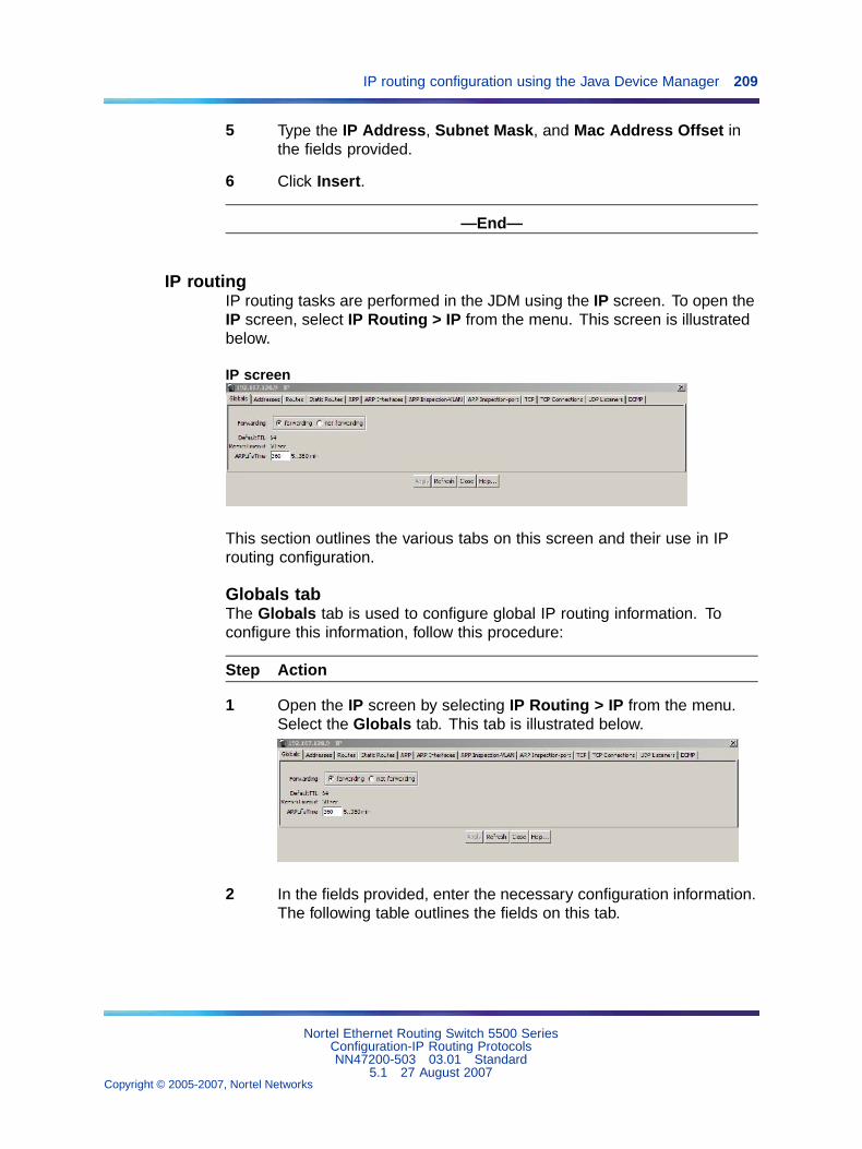
IP routing configuration using the Java Device Manager 209
5 Type the IP Address, Subnet Mask, and Mac Address Offset inthe fields provided.
6 Click Insert.
—End—
IP routingIP routing tasks are performed in the JDM using the IP screen. To open theIP screen, select IP Routing > IP from the menu. This screen is illustratedbelow.
IP screen
This section outlines the various tabs on this screen and their use in IProuting configuration.
Globals tabThe Globals tab is used to configure global IP routing information. Toconfigure this information, follow this procedure:
Step Action
1 Open the IP screen by selecting IP Routing > IP from the menu.Select the Globals tab. This tab is illustrated below.
2 In the fields provided, enter the necessary configuration information.The following table outlines the fields on this tab.
Nortel Ethernet Routing Switch 5500 SeriesConfiguration-IP Routing ProtocolsNN47200-503 03.01 Standard
5.1 27 August 2007Copyright © 2005-2007, Nortel Networks
.
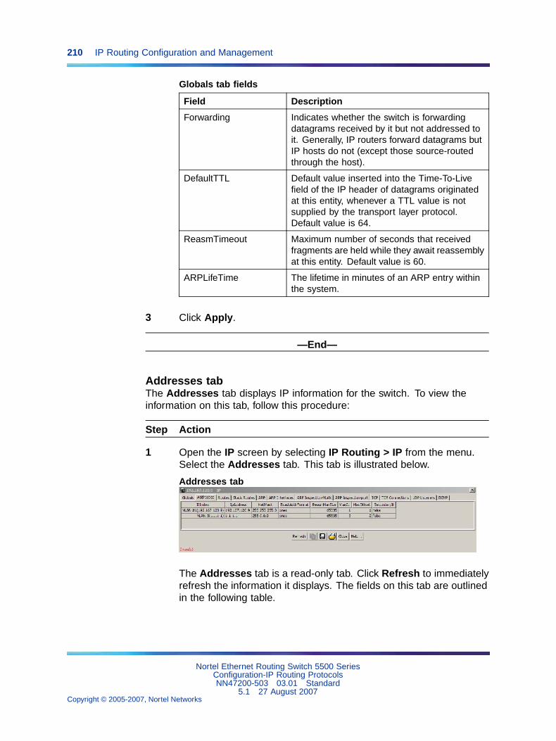
210 IP Routing Configuration and Management
Globals tab fields
Field Description
Forwarding Indicates whether the switch is forwardingdatagrams received by it but not addressed toit. Generally, IP routers forward datagrams butIP hosts do not (except those source-routedthrough the host).
DefaultTTL Default value inserted into the Time-To-Livefield of the IP header of datagrams originatedat this entity, whenever a TTL value is notsupplied by the transport layer protocol.Default value is 64.
ReasmTimeout Maximum number of seconds that receivedfragments are held while they await reassemblyat this entity. Default value is 60.
ARPLifeTime The lifetime in minutes of an ARP entry withinthe system.
3 Click Apply.
—End—
Addresses tabThe Addresses tab displays IP information for the switch. To view theinformation on this tab, follow this procedure:
Step Action
1 Open the IP screen by selecting IP Routing > IP from the menu.Select the Addresses tab. This tab is illustrated below.
Addresses tab
The Addresses tab is a read-only tab. Click Refresh to immediatelyrefresh the information it displays. The fields on this tab are outlinedin the following table.
Nortel Ethernet Routing Switch 5500 SeriesConfiguration-IP Routing ProtocolsNN47200-503 03.01 Standard
5.1 27 August 2007Copyright © 2005-2007, Nortel Networks
.
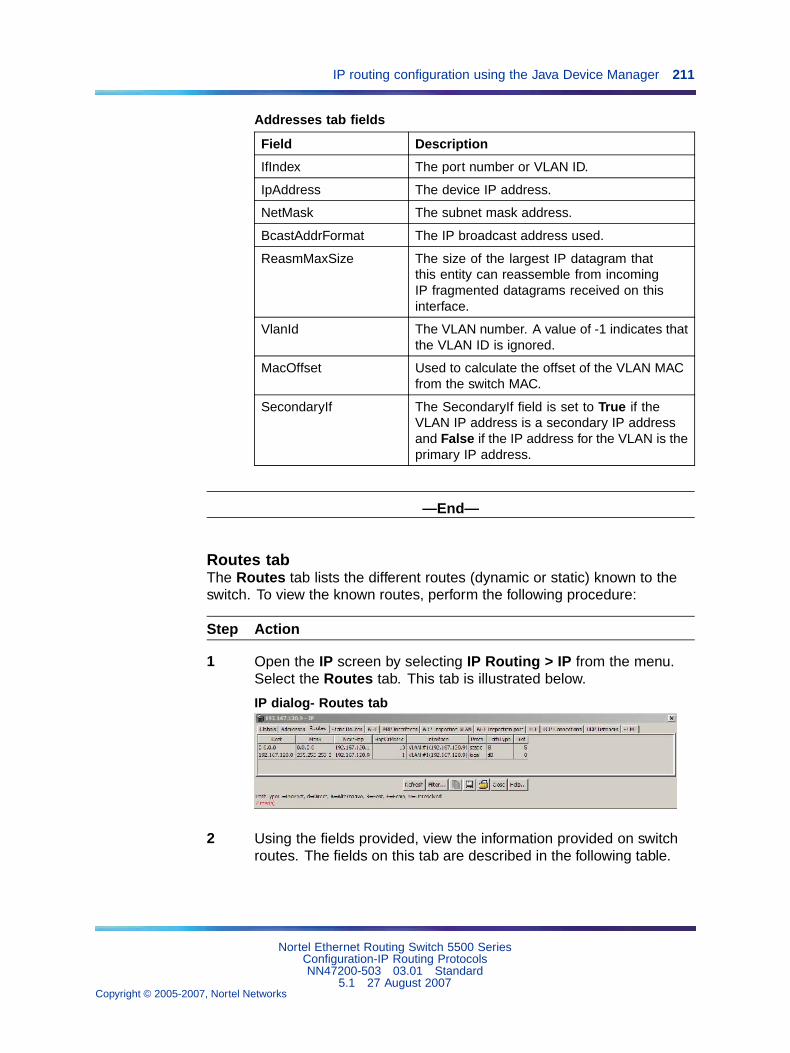
IP routing configuration using the Java Device Manager 211
Addresses tab fields
Field Description
IfIndex The port number or VLAN ID.
IpAddress The device IP address.
NetMask The subnet mask address.
BcastAddrFormat The IP broadcast address used.
ReasmMaxSize The size of the largest IP datagram thatthis entity can reassemble from incomingIP fragmented datagrams received on thisinterface.
VlanId The VLAN number. A value of -1 indicates thatthe VLAN ID is ignored.
MacOffset Used to calculate the offset of the VLAN MACfrom the switch MAC.
SecondaryIf The SecondaryIf field is set to True if theVLAN IP address is a secondary IP addressand False if the IP address for the VLAN is theprimary IP address.
—End—
Routes tabThe Routes tab lists the different routes (dynamic or static) known to theswitch. To view the known routes, perform the following procedure:
Step Action
1 Open the IP screen by selecting IP Routing > IP from the menu.Select the Routes tab. This tab is illustrated below.
IP dialog- Routes tab
2 Using the fields provided, view the information provided on switchroutes. The fields on this tab are described in the following table.
Nortel Ethernet Routing Switch 5500 SeriesConfiguration-IP Routing ProtocolsNN47200-503 03.01 Standard
5.1 27 August 2007Copyright © 2005-2007, Nortel Networks
.
212 IP Routing Configuration and Management
Routes tab fields
Field Description
Dest The destination address of the route.
Mask The subnet mask used by the route destination.
NextHop The next hop in the listed route.
HopOrMetric The OSPF hop count or metric associated withthe route.
Interface The interface associated with the route.
Proto The protocol associated with the route.
PathType The route path type.
Pref The preference value associated with the route.
—End—
Note: Routes will not be displayed until at least one port in the VLANhas link.
The route list can be updated by clicking the Refresh button. The route listcan also be filtered. This is described below.
Filtering route informationThe Routes tab can be filtered to display only the desired switch routes.Use the following procedure to filter the Routes tab:
Step Action
1 With the Routes tab open, click the Filter button. The Filter dialogis displayed. This dialog is illustrated below.
Nortel Ethernet Routing Switch 5500 SeriesConfiguration-IP Routing ProtocolsNN47200-503 03.01 Standard
5.1 27 August 2007Copyright © 2005-2007, Nortel Networks
.
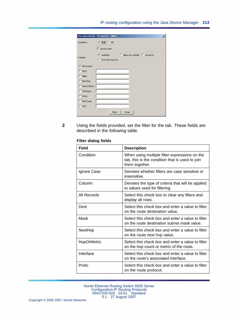
IP routing configuration using the Java Device Manager 213
2 Using the fields provided, set the filter for the tab. These fields aredescribed in the following table.
Filter dialog fields
Field Description
Condition When using multiple filter expressions on thetab, this is the condition that is used to jointhem together.
Ignore Case Denotes whether filters are case sensitive orinsensitive.
Column Denotes the type of criteria that will be appliedto values used for filtering.
All Records Select this check box to clear any filters anddisplay all rows.
Dest Select this check box and enter a value to filteron the route destination value.
Mask Select this check box and enter a value to filteron the route destination subnet mask value.
NextHop Select this check box and enter a value to filteron the route next hop value.
HopOrMetric Select this check box and enter a value to filteron the hop count or metric of the route.
Interface Select this check box and enter a value to filteron the route’s associated interface.
Proto Select this check box and enter a value to filteron the route protocol.
Nortel Ethernet Routing Switch 5500 SeriesConfiguration-IP Routing ProtocolsNN47200-503 03.01 Standard
5.1 27 August 2007Copyright © 2005-2007, Nortel Networks
.
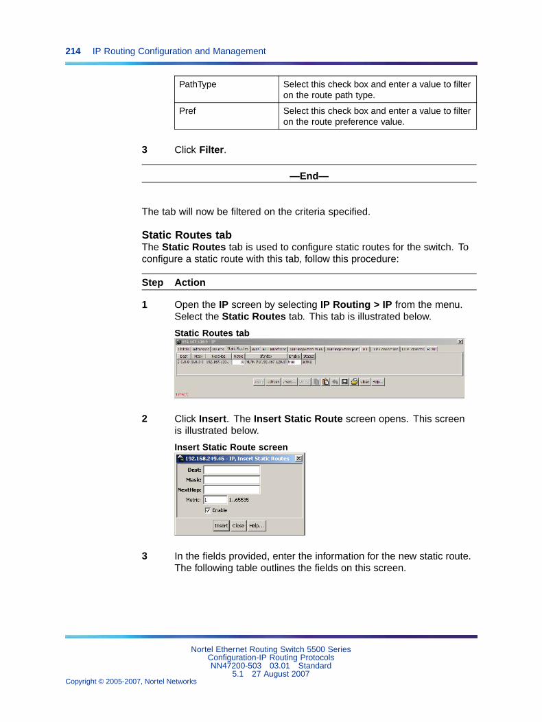
214 IP Routing Configuration and Management
PathType Select this check box and enter a value to filteron the route path type.
Pref Select this check box and enter a value to filteron the route preference value.
3 Click Filter.
—End—
The tab will now be filtered on the criteria specified.
Static Routes tabThe Static Routes tab is used to configure static routes for the switch. Toconfigure a static route with this tab, follow this procedure:
Step Action
1 Open the IP screen by selecting IP Routing > IP from the menu.Select the Static Routes tab. This tab is illustrated below.
Static Routes tab
2 Click Insert. The Insert Static Route screen opens. This screenis illustrated below.
Insert Static Route screen
3 In the fields provided, enter the information for the new static route.The following table outlines the fields on this screen.
Nortel Ethernet Routing Switch 5500 SeriesConfiguration-IP Routing ProtocolsNN47200-503 03.01 Standard
5.1 27 August 2007Copyright © 2005-2007, Nortel Networks
.
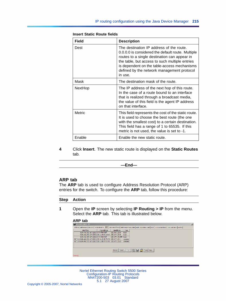
IP routing configuration using the Java Device Manager 215
Insert Static Route fields
Field Description
Dest The destination IP address of the route.0.0.0.0 is considered the default route. Multipleroutes to a single destination can appear inthe table, but access to such multiple entriesis dependent on the table-access mechanismsdefined by the network management protocolin use.
Mask The destination mask of the route.
NextHop The IP address of the next hop of this route.In the case of a route bound to an interfacethat is realized through a broadcast media,the value of this field is the agent IP addresson that interface.
Metric This field represents the cost of the static route.It is used to choose the best route (the onewith the smallest cost) to a certain destination.This field has a range of 1 to 65535. If thismetric is not used, the value is set to -1.
Enable Enable the new static route.
4 Click Insert. The new static route is displayed on the Static Routestab.
—End—
ARP tabThe ARP tab is used to configure Address Resolution Protocol (ARP)entries for the switch. To configure the ARP tab, follow this procedure:
Step Action
1 Open the IP screen by selecting IP Routing > IP from the menu.Select the ARP tab. This tab is illustrated below.
ARP tab
Nortel Ethernet Routing Switch 5500 SeriesConfiguration-IP Routing ProtocolsNN47200-503 03.01 Standard
5.1 27 August 2007Copyright © 2005-2007, Nortel Networks
.
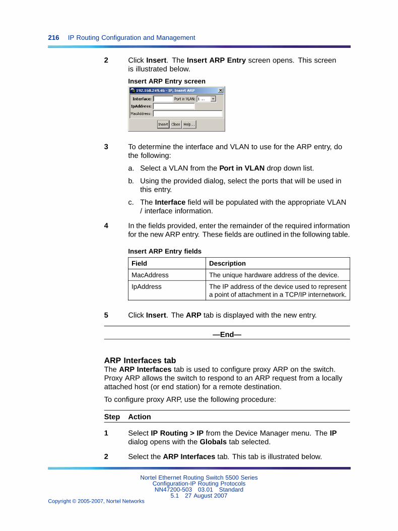
216 IP Routing Configuration and Management
2 Click Insert. The Insert ARP Entry screen opens. This screenis illustrated below.
Insert ARP Entry screen
3 To determine the interface and VLAN to use for the ARP entry, dothe following:
a. Select a VLAN from the Port in VLAN drop down list.
b. Using the provided dialog, select the ports that will be used inthis entry.
c. The Interface field will be populated with the appropriate VLAN/ interface information.
4 In the fields provided, enter the remainder of the required informationfor the new ARP entry. These fields are outlined in the following table.
Insert ARP Entry fields
Field Description
MacAddress The unique hardware address of the device.
IpAddress The IP address of the device used to representa point of attachment in a TCP/IP internetwork.
5 Click Insert. The ARP tab is displayed with the new entry.
—End—
ARP Interfaces tabThe ARP Interfaces tab is used to configure proxy ARP on the switch.Proxy ARP allows the switch to respond to an ARP request from a locallyattached host (or end station) for a remote destination.
To configure proxy ARP, use the following procedure:
Step Action
1 Select IP Routing > IP from the Device Manager menu. The IPdialog opens with the Globals tab selected.
2 Select the ARP Interfaces tab. This tab is illustrated below.
Nortel Ethernet Routing Switch 5500 SeriesConfiguration-IP Routing ProtocolsNN47200-503 03.01 Standard
5.1 27 August 2007Copyright © 2005-2007, Nortel Networks
.
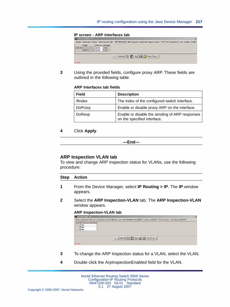
IP routing configuration using the Java Device Manager 217
IP screen - ARP Interfaces tab
3 Using the provided fields, configure proxy ARP. These fields areoutlined in the following table.
ARP Interfaces tab fields
Field Description
IfIndex The index of the configured switch interface.
DoProxy Enable or disable proxy ARP on the interface.
DoResp Enable or disable the sending of ARP responseson the specified interface.
4 Click Apply.
—End—
ARP Inspection VLAN tabTo view and change ARP inspection status for VLANs, use the followingprocedure:
Step Action
1 From the Device Manager, select IP Routing > IP. The IP windowappears.
2 Select the ARP Inspection-VLAN tab. The ARP Inspection-VLANwindow appears.
ARP Inspection-VLAN tab
3 To change the ARP Inspection status for a VLAN, select the VLAN.
4 Double click the ArpInspectionEnabled field for the VLAN.
Nortel Ethernet Routing Switch 5500 SeriesConfiguration-IP Routing ProtocolsNN47200-503 03.01 Standard
5.1 27 August 2007Copyright © 2005-2007, Nortel Networks
.
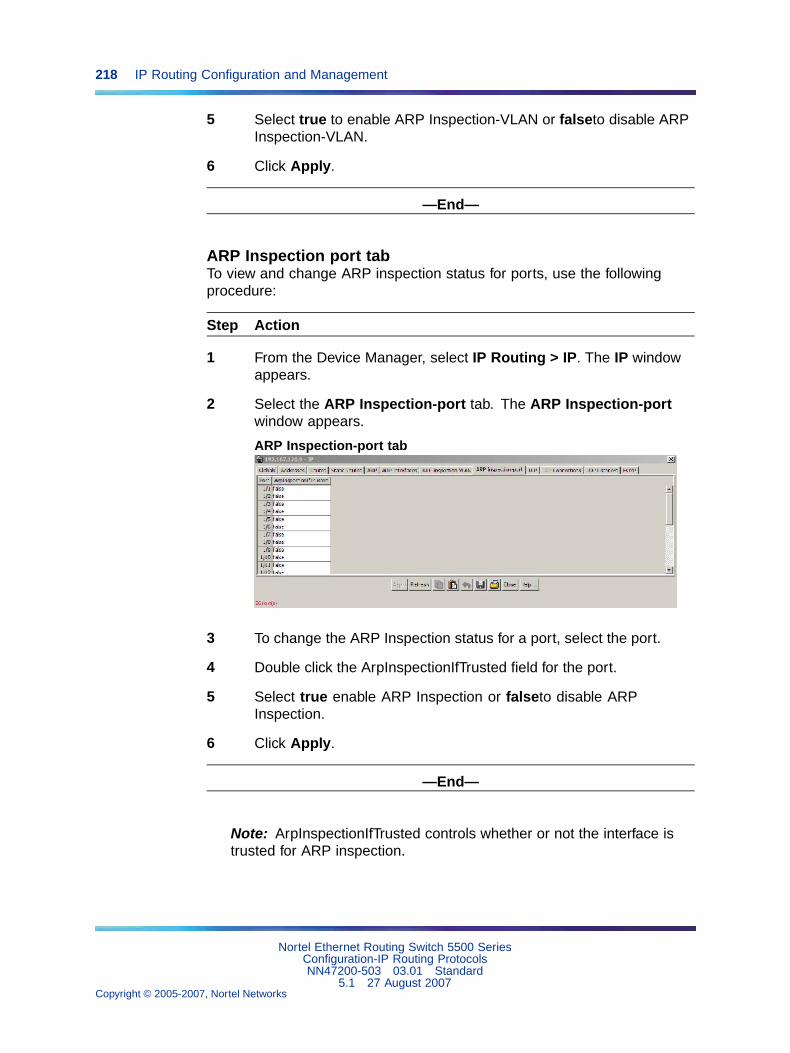
218 IP Routing Configuration and Management
5 Select true to enable ARP Inspection-VLAN or falseto disable ARPInspection-VLAN.
6 Click Apply.
—End—
ARP Inspection port tabTo view and change ARP inspection status for ports, use the followingprocedure:
Step Action
1 From the Device Manager, select IP Routing > IP. The IP windowappears.
2 Select the ARP Inspection-port tab. The ARP Inspection-portwindow appears.
ARP Inspection-port tab
3 To change the ARP Inspection status for a port, select the port.
4 Double click the ArpInspectionIfTrusted field for the port.
5 Select true enable ARP Inspection or falseto disable ARPInspection.
6 Click Apply.
—End—
Note: ArpInspectionIfTrusted controls whether or not the interface istrusted for ARP inspection.
Nortel Ethernet Routing Switch 5500 SeriesConfiguration-IP Routing ProtocolsNN47200-503 03.01 Standard
5.1 27 August 2007Copyright © 2005-2007, Nortel Networks
.
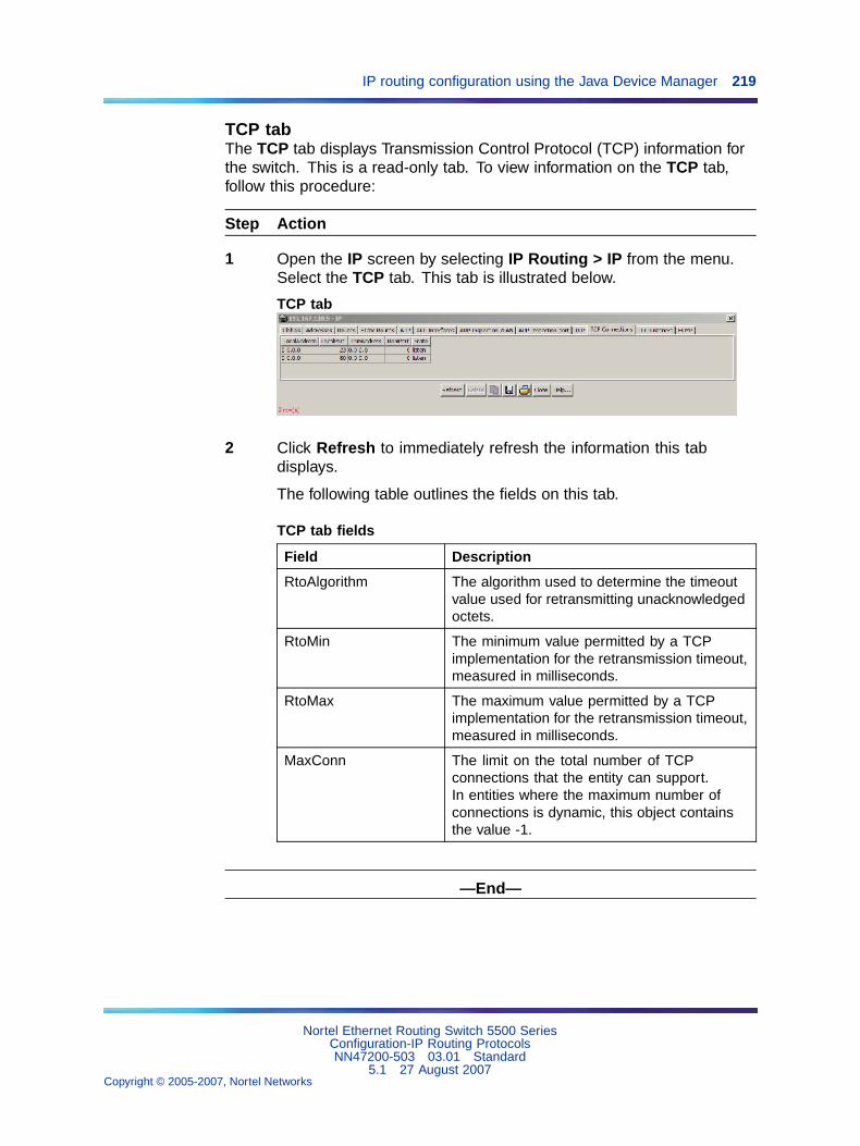
IP routing configuration using the Java Device Manager 219
TCP tabThe TCP tab displays Transmission Control Protocol (TCP) information forthe switch. This is a read-only tab. To view information on the TCP tab,follow this procedure:
Step Action
1 Open the IP screen by selecting IP Routing > IP from the menu.Select the TCP tab. This tab is illustrated below.
TCP tab
2 Click Refresh to immediately refresh the information this tabdisplays.
The following table outlines the fields on this tab.
TCP tab fields
Field Description
RtoAlgorithm The algorithm used to determine the timeoutvalue used for retransmitting unacknowledgedoctets.
RtoMin The minimum value permitted by a TCPimplementation for the retransmission timeout,measured in milliseconds.
RtoMax The maximum value permitted by a TCPimplementation for the retransmission timeout,measured in milliseconds.
MaxConn The limit on the total number of TCPconnections that the entity can support.In entities where the maximum number ofconnections is dynamic, this object containsthe value -1.
—End—
Nortel Ethernet Routing Switch 5500 SeriesConfiguration-IP Routing ProtocolsNN47200-503 03.01 Standard
5.1 27 August 2007Copyright © 2005-2007, Nortel Networks
.

220 IP Routing Configuration and Management
TCP Connections tabThis tab displays information on the current TCP connections the switchmaintains. This tab is read-only. To view information on this tab, followthis procedure:
Step Action
1 Open the IP screen by selecting IP Routing > IP from the menu.Select the TCP Connections tab. This tab is illustrated below.
TCP Connections tab
2 Click Refresh to immediately refresh the information this tabdisplays.
The following table describes the fields on this tab.
TCP Connections tab fields
Field Description
LocalAddress The local IP address for this TCP connection.In the case of a connection in the listen state,which is willing to accept connections for anyIP interface associated with the node, thevalue 0.0.0.0 is used.
LocalPort The local port number for this TCP connection.
RemAddress The remote IP address for this TCP connection.
RemPort The remote port number for this TCPconnection.
State The state of this TCP connection.
—End—
UDP Listeners tabThis tab displays information on the UDP listeners currently maintained bythe switch. This tab is read-only. To view the information on this tab, followthis procedure:
Nortel Ethernet Routing Switch 5500 SeriesConfiguration-IP Routing ProtocolsNN47200-503 03.01 Standard
5.1 27 August 2007Copyright © 2005-2007, Nortel Networks
.
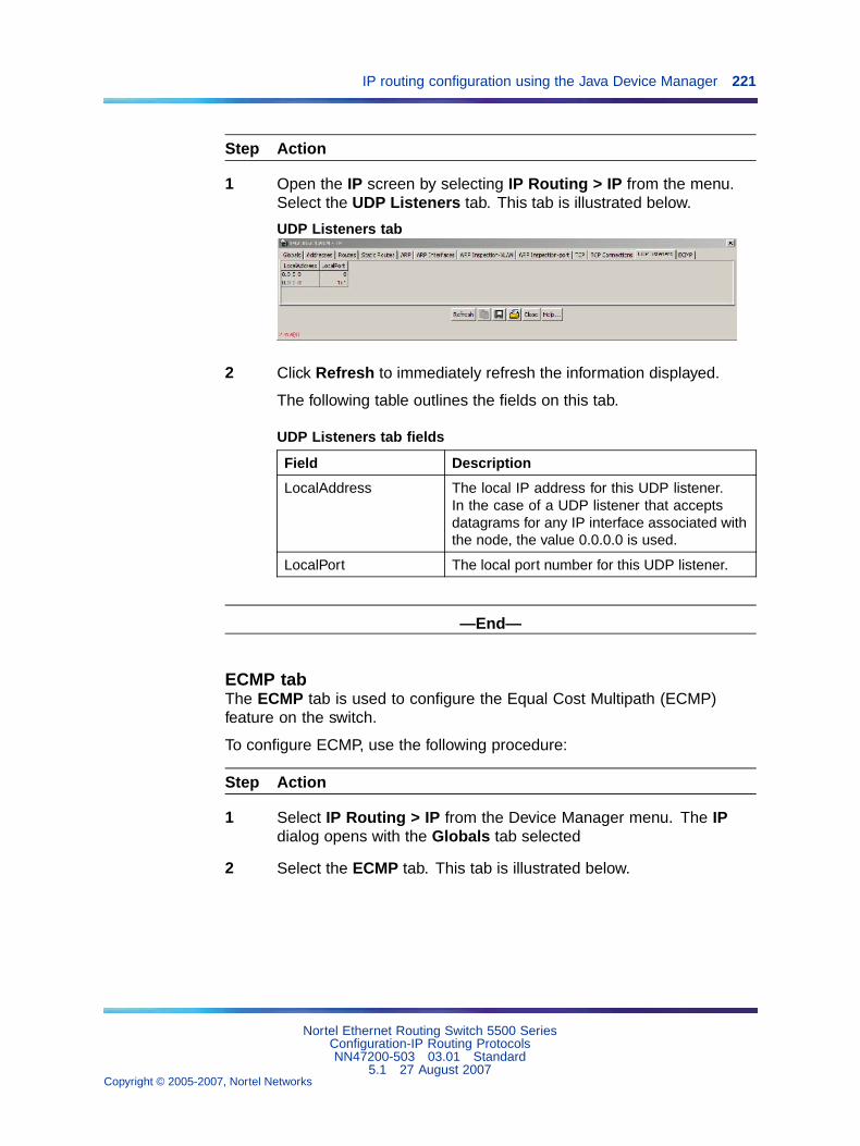
IP routing configuration using the Java Device Manager 221
Step Action
1 Open the IP screen by selecting IP Routing > IP from the menu.Select the UDP Listeners tab. This tab is illustrated below.
UDP Listeners tab
2 Click Refresh to immediately refresh the information displayed.
The following table outlines the fields on this tab.
UDP Listeners tab fields
Field Description
LocalAddress The local IP address for this UDP listener.In the case of a UDP listener that acceptsdatagrams for any IP interface associated withthe node, the value 0.0.0.0 is used.
LocalPort The local port number for this UDP listener.
—End—
ECMP tabThe ECMP tab is used to configure the Equal Cost Multipath (ECMP)feature on the switch.
To configure ECMP, use the following procedure:
Step Action
1 Select IP Routing > IP from the Device Manager menu. The IPdialog opens with the Globals tab selected
2 Select the ECMP tab. This tab is illustrated below.
Nortel Ethernet Routing Switch 5500 SeriesConfiguration-IP Routing ProtocolsNN47200-503 03.01 Standard
5.1 27 August 2007Copyright © 2005-2007, Nortel Networks
.
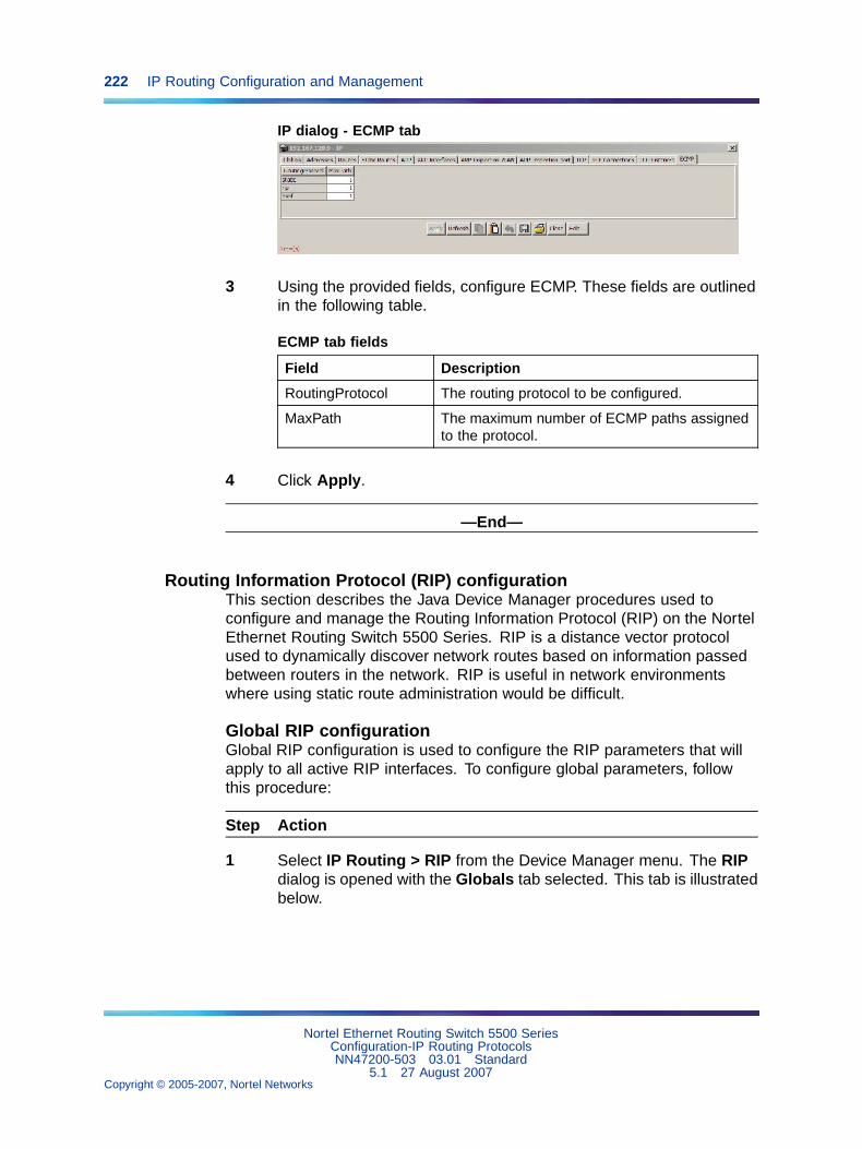
222 IP Routing Configuration and Management
IP dialog - ECMP tab
3 Using the provided fields, configure ECMP. These fields are outlinedin the following table.
ECMP tab fields
Field Description
RoutingProtocol The routing protocol to be configured.
MaxPath The maximum number of ECMP paths assignedto the protocol.
4 Click Apply.
—End—
Routing Information Protocol (RIP) configurationThis section describes the Java Device Manager procedures used toconfigure and manage the Routing Information Protocol (RIP) on the NortelEthernet Routing Switch 5500 Series. RIP is a distance vector protocolused to dynamically discover network routes based on information passedbetween routers in the network. RIP is useful in network environmentswhere using static route administration would be difficult.
Global RIP configurationGlobal RIP configuration is used to configure the RIP parameters that willapply to all active RIP interfaces. To configure global parameters, followthis procedure:
Step Action
1 Select IP Routing > RIP from the Device Manager menu. The RIPdialog is opened with the Globals tab selected. This tab is illustratedbelow.
Nortel Ethernet Routing Switch 5500 SeriesConfiguration-IP Routing ProtocolsNN47200-503 03.01 Standard
5.1 27 August 2007Copyright © 2005-2007, Nortel Networks
.
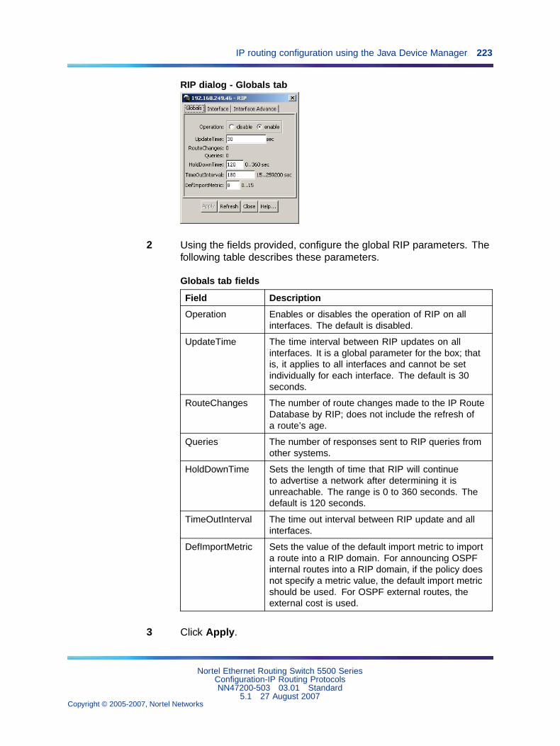
IP routing configuration using the Java Device Manager 223
RIP dialog - Globals tab
2 Using the fields provided, configure the global RIP parameters. Thefollowing table describes these parameters.
Globals tab fields
Field Description
Operation Enables or disables the operation of RIP on allinterfaces. The default is disabled.
UpdateTime The time interval between RIP updates on allinterfaces. It is a global parameter for the box; thatis, it applies to all interfaces and cannot be setindividually for each interface. The default is 30seconds.
RouteChanges The number of route changes made to the IP RouteDatabase by RIP; does not include the refresh ofa route’s age.
Queries The number of responses sent to RIP queries fromother systems.
HoldDownTime Sets the length of time that RIP will continueto advertise a network after determining it isunreachable. The range is 0 to 360 seconds. Thedefault is 120 seconds.
TimeOutInterval The time out interval between RIP update and allinterfaces.
DefImportMetric Sets the value of the default import metric to importa route into a RIP domain. For announcing OSPFinternal routes into a RIP domain, if the policy doesnot specify a metric value, the default import metricshould be used. For OSPF external routes, theexternal cost is used.
3 Click Apply.
Nortel Ethernet Routing Switch 5500 SeriesConfiguration-IP Routing ProtocolsNN47200-503 03.01 Standard
5.1 27 August 2007Copyright © 2005-2007, Nortel Networks
.
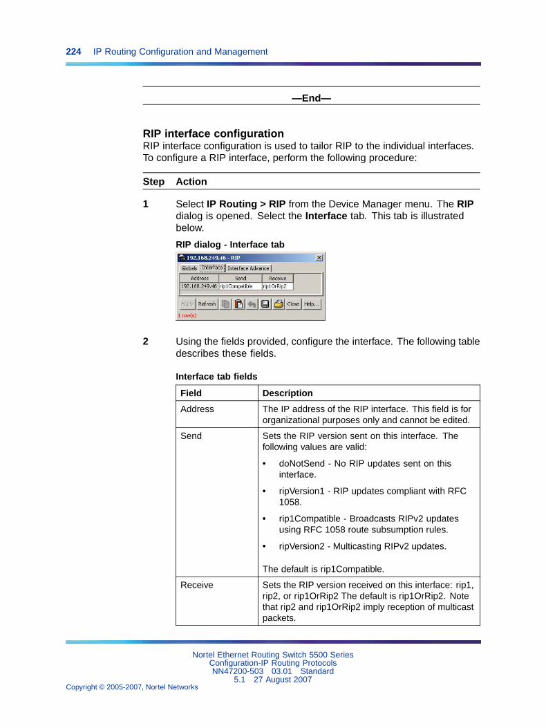
224 IP Routing Configuration and Management
—End—
RIP interface configurationRIP interface configuration is used to tailor RIP to the individual interfaces.To configure a RIP interface, perform the following procedure:
Step Action
1 Select IP Routing > RIP from the Device Manager menu. The RIPdialog is opened. Select the Interface tab. This tab is illustratedbelow.
RIP dialog - Interface tab
2 Using the fields provided, configure the interface. The following tabledescribes these fields.
Interface tab fields
Field Description
Address The IP address of the RIP interface. This field is fororganizational purposes only and cannot be edited.
Send Sets the RIP version sent on this interface. Thefollowing values are valid:
• doNotSend - No RIP updates sent on thisinterface.
• ripVersion1 - RIP updates compliant with RFC1058.
• rip1Compatible - Broadcasts RIPv2 updatesusing RFC 1058 route subsumption rules.
• ripVersion2 - Multicasting RIPv2 updates.
The default is rip1Compatible.
Receive Sets the RIP version received on this interface: rip1,rip2, or rip1OrRip2 The default is rip1OrRip2. Notethat rip2 and rip1OrRip2 imply reception of multicastpackets.
Nortel Ethernet Routing Switch 5500 SeriesConfiguration-IP Routing ProtocolsNN47200-503 03.01 Standard
5.1 27 August 2007Copyright © 2005-2007, Nortel Networks
.
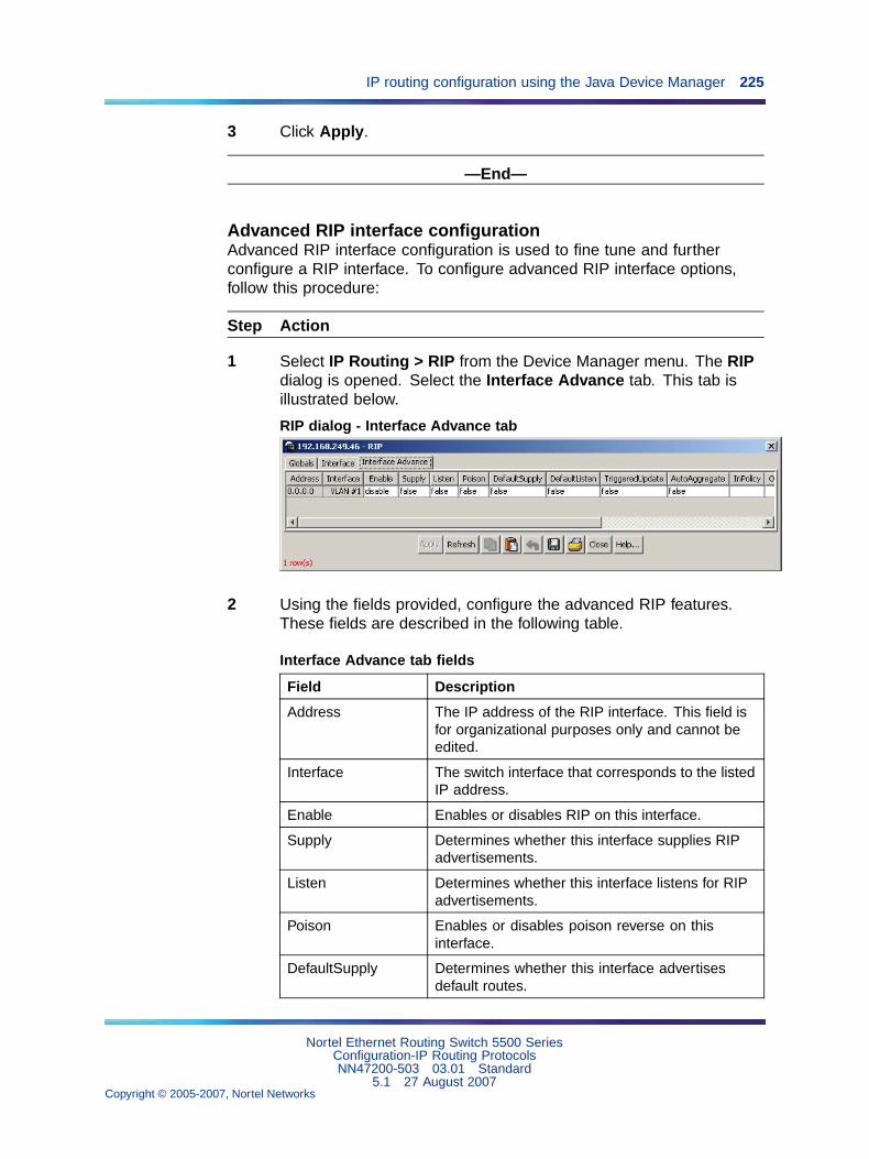
IP routing configuration using the Java Device Manager 225
3 Click Apply.
—End—
Advanced RIP interface configurationAdvanced RIP interface configuration is used to fine tune and furtherconfigure a RIP interface. To configure advanced RIP interface options,follow this procedure:
Step Action
1 Select IP Routing > RIP from the Device Manager menu. The RIPdialog is opened. Select the Interface Advance tab. This tab isillustrated below.
RIP dialog - Interface Advance tab
2 Using the fields provided, configure the advanced RIP features.These fields are described in the following table.
Interface Advance tab fields
Field Description
Address The IP address of the RIP interface. This field isfor organizational purposes only and cannot beedited.
Interface The switch interface that corresponds to the listedIP address.
Enable Enables or disables RIP on this interface.
Supply Determines whether this interface supplies RIPadvertisements.
Listen Determines whether this interface listens for RIPadvertisements.
Poison Enables or disables poison reverse on thisinterface.
DefaultSupply Determines whether this interface advertisesdefault routes.
Nortel Ethernet Routing Switch 5500 SeriesConfiguration-IP Routing ProtocolsNN47200-503 03.01 Standard
5.1 27 August 2007Copyright © 2005-2007, Nortel Networks
.
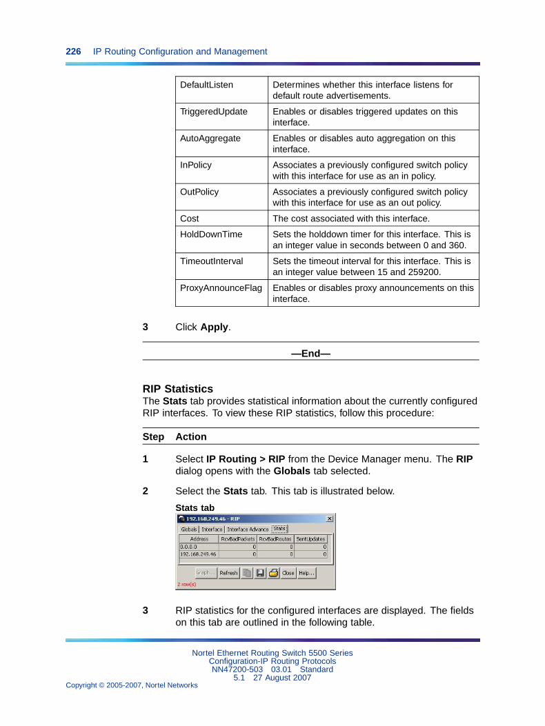
226 IP Routing Configuration and Management
DefaultListen Determines whether this interface listens fordefault route advertisements.
TriggeredUpdate Enables or disables triggered updates on thisinterface.
AutoAggregate Enables or disables auto aggregation on thisinterface.
InPolicy Associates a previously configured switch policywith this interface for use as an in policy.
OutPolicy Associates a previously configured switch policywith this interface for use as an out policy.
Cost The cost associated with this interface.
HoldDownTime Sets the holddown timer for this interface. This isan integer value in seconds between 0 and 360.
TimeoutInterval Sets the timeout interval for this interface. This isan integer value between 15 and 259200.
ProxyAnnounceFlag Enables or disables proxy announcements on thisinterface.
3 Click Apply.
—End—
RIP StatisticsThe Stats tab provides statistical information about the currently configuredRIP interfaces. To view these RIP statistics, follow this procedure:
Step Action
1 Select IP Routing > RIP from the Device Manager menu. The RIPdialog opens with the Globals tab selected.
2 Select the Stats tab. This tab is illustrated below.
Stats tab
3 RIP statistics for the configured interfaces are displayed. The fieldson this tab are outlined in the following table.
Nortel Ethernet Routing Switch 5500 SeriesConfiguration-IP Routing ProtocolsNN47200-503 03.01 Standard
5.1 27 August 2007Copyright © 2005-2007, Nortel Networks
.
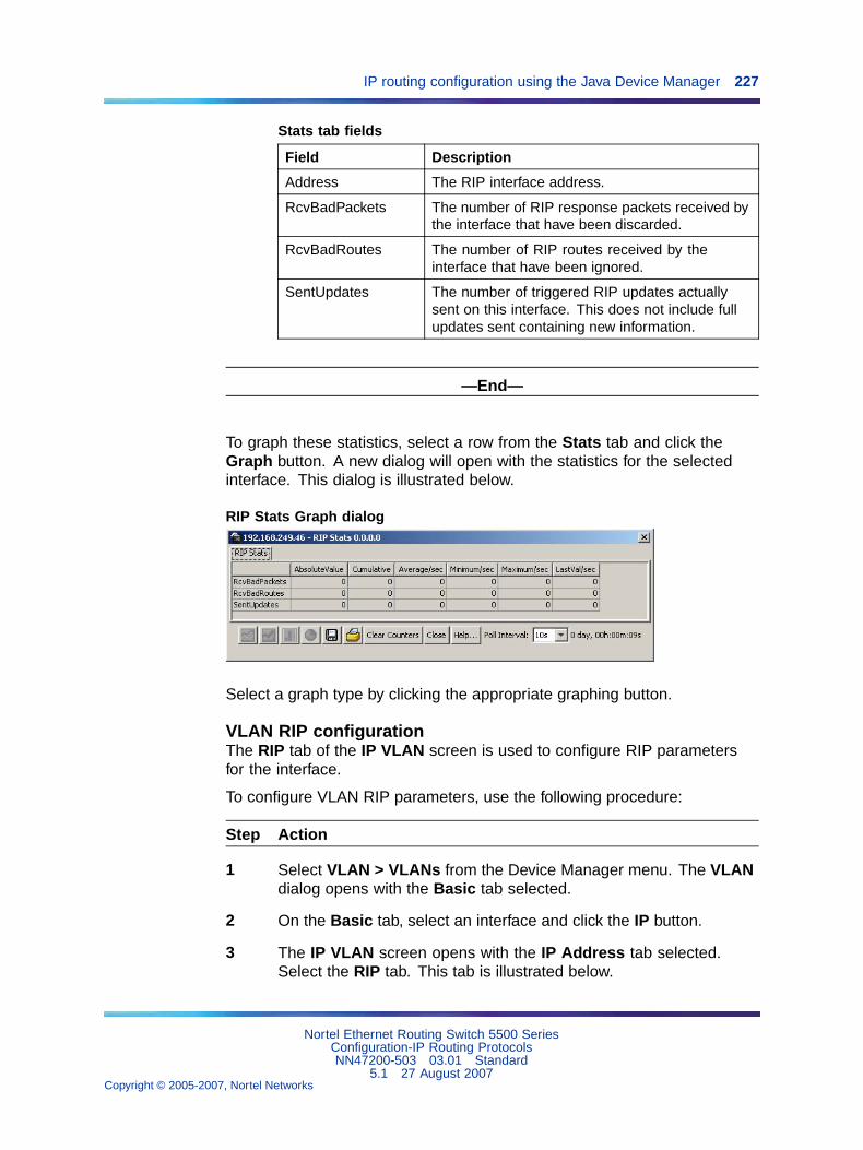
IP routing configuration using the Java Device Manager 227
Stats tab fields
Field Description
Address The RIP interface address.
RcvBadPackets The number of RIP response packets received bythe interface that have been discarded.
RcvBadRoutes The number of RIP routes received by theinterface that have been ignored.
SentUpdates The number of triggered RIP updates actuallysent on this interface. This does not include fullupdates sent containing new information.
—End—
To graph these statistics, select a row from the Stats tab and click theGraph button. A new dialog will open with the statistics for the selectedinterface. This dialog is illustrated below.
RIP Stats Graph dialog
Select a graph type by clicking the appropriate graphing button.
VLAN RIP configurationThe RIP tab of the IP VLAN screen is used to configure RIP parametersfor the interface.
To configure VLAN RIP parameters, use the following procedure:
Step Action
1 Select VLAN > VLANs from the Device Manager menu. The VLANdialog opens with the Basic tab selected.
2 On the Basic tab, select an interface and click the IP button.
3 The IP VLAN screen opens with the IP Address tab selected.Select the RIP tab. This tab is illustrated below.
Nortel Ethernet Routing Switch 5500 SeriesConfiguration-IP Routing ProtocolsNN47200-503 03.01 Standard
5.1 27 August 2007Copyright © 2005-2007, Nortel Networks
.
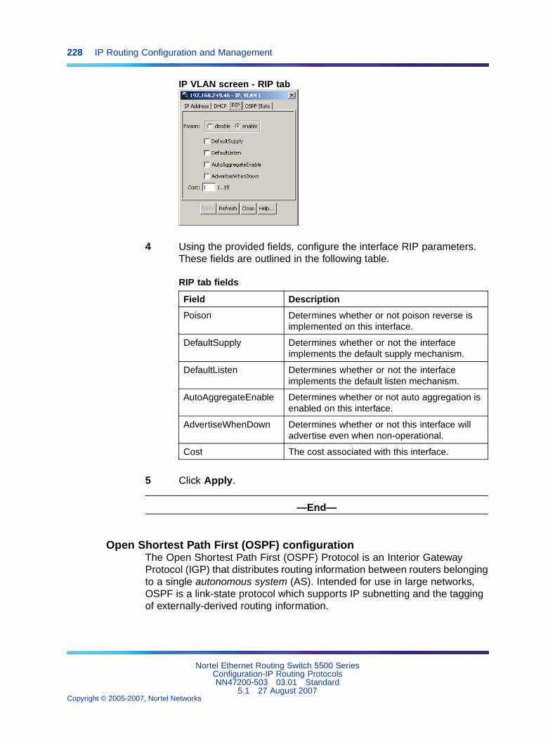
228 IP Routing Configuration and Management
IP VLAN screen - RIP tab
4 Using the provided fields, configure the interface RIP parameters.These fields are outlined in the following table.
RIP tab fields
Field Description
Poison Determines whether or not poison reverse isimplemented on this interface.
DefaultSupply Determines whether or not the interfaceimplements the default supply mechanism.
DefaultListen Determines whether or not the interfaceimplements the default listen mechanism.
AutoAggregateEnable Determines whether or not auto aggregation isenabled on this interface.
AdvertiseWhenDown Determines whether or not this interface willadvertise even when non-operational.
Cost The cost associated with this interface.
5 Click Apply.
—End—
Open Shortest Path First (OSPF) configurationThe Open Shortest Path First (OSPF) Protocol is an Interior GatewayProtocol (IGP) that distributes routing information between routers belongingto a single autonomous system (AS). Intended for use in large networks,OSPF is a link-state protocol which supports IP subnetting and the taggingof externally-derived routing information.
Nortel Ethernet Routing Switch 5500 SeriesConfiguration-IP Routing ProtocolsNN47200-503 03.01 Standard
5.1 27 August 2007Copyright © 2005-2007, Nortel Networks
.
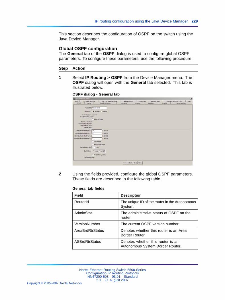
IP routing configuration using the Java Device Manager 229
This section describes the configuration of OSPF on the switch using theJava Device Manager.
Global OSPF configurationThe General tab of the OSPF dialog is used to configure global OSPFparameters. To configure these parameters, use the following procedure:
Step Action
1 Select IP Routing > OSPF from the Device Manager menu. TheOSPF dialog will open with the General tab selected. This tab isillustrated below.
OSPF dialog - General tab
2 Using the fields provided, configure the global OSPF parameters.These fields are described in the following table.
General tab fields
Field Description
RouterId The unique ID of the router in the AutonomousSystem.
AdminStat The administrative status of OSPF on therouter.
VersionNumber The current OSPF version number.
AreaBrdRtrStatus Denotes whether this router is an AreaBorder Router.
ASBrdRtrStatus Denotes whether this router is anAutonomous System Border Router.
Nortel Ethernet Routing Switch 5500 SeriesConfiguration-IP Routing ProtocolsNN47200-503 03.01 Standard
5.1 27 August 2007Copyright © 2005-2007, Nortel Networks
.
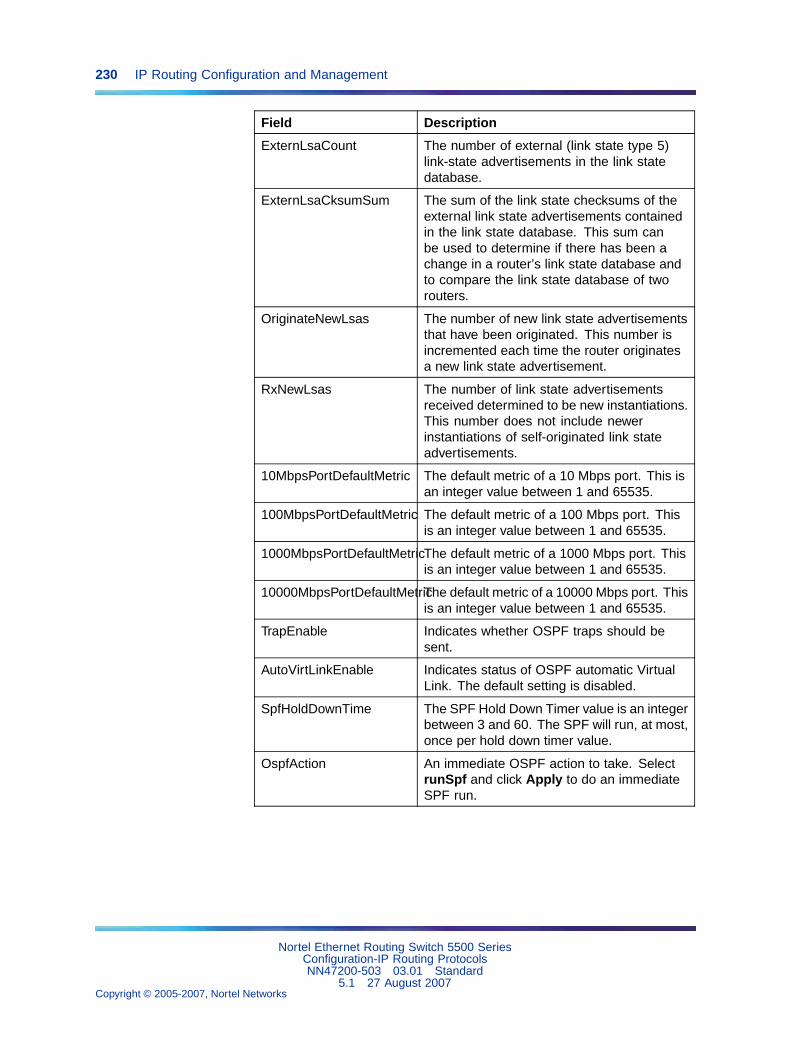
230 IP Routing Configuration and Management
Field Description
ExternLsaCount The number of external (link state type 5)link-state advertisements in the link statedatabase.
ExternLsaCksumSum The sum of the link state checksums of theexternal link state advertisements containedin the link state database. This sum canbe used to determine if there has been achange in a router’s link state database andto compare the link state database of tworouters.
OriginateNewLsas The number of new link state advertisementsthat have been originated. This number isincremented each time the router originatesa new link state advertisement.
RxNewLsas The number of link state advertisementsreceived determined to be new instantiations.This number does not include newerinstantiations of self-originated link stateadvertisements.
10MbpsPortDefaultMetric The default metric of a 10 Mbps port. This isan integer value between 1 and 65535.
100MbpsPortDefaultMetric The default metric of a 100 Mbps port. Thisis an integer value between 1 and 65535.
1000MbpsPortDefaultMetricThe default metric of a 1000 Mbps port. Thisis an integer value between 1 and 65535.
10000MbpsPortDefaultMetricThe default metric of a 10000 Mbps port. Thisis an integer value between 1 and 65535.
TrapEnable Indicates whether OSPF traps should besent.
AutoVirtLinkEnable Indicates status of OSPF automatic VirtualLink. The default setting is disabled.
SpfHoldDownTime The SPF Hold Down Timer value is an integerbetween 3 and 60. The SPF will run, at most,once per hold down timer value.
OspfAction An immediate OSPF action to take. SelectrunSpf and click Apply to do an immediateSPF run.
Nortel Ethernet Routing Switch 5500 SeriesConfiguration-IP Routing ProtocolsNN47200-503 03.01 Standard
5.1 27 August 2007Copyright © 2005-2007, Nortel Networks
.
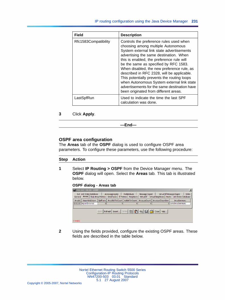
IP routing configuration using the Java Device Manager 231
Field Description
Rfc1583Compatibility Controls the preference rules used whenchoosing among multiple AutonomousSystem external link state advertisementsadvertising the same destination. Whenthis is enabled, the preference rule willbe the same as specified by RFC 1583.When disabled, the new preference rule, asdescribed in RFC 2328, will be applicable.This potentially prevents the routing loopswhen Autonomous System external link stateadvertisements for the same destination havebeen originated from different areas.
LastSpfRun Used to indicate the time the last SPFcalculation was done.
3 Click Apply.
—End—
OSPF area configurationThe Areas tab of the OSPF dialog is used to configure OSPF areaparameters. To configure these parameters, use the following procedure:
Step Action
1 Select IP Routing > OSPF from the Device Manager menu. TheOSPF dialog will open. Select the Areas tab. This tab is illustratedbelow.
OSPF dialog - Areas tab
2 Using the fields provided, configure the existing OSPF areas. Thesefields are described in the table below.
Nortel Ethernet Routing Switch 5500 SeriesConfiguration-IP Routing ProtocolsNN47200-503 03.01 Standard
5.1 27 August 2007Copyright © 2005-2007, Nortel Networks
.
232 IP Routing Configuration and Management
Areas tab fields
Field Description
AreaId The area’s unique identifier. Area ID 0.0.0.0 isused for the OSPF backbone.
ImportAsExtern The area’s support for importing AutonomousSystem external link state advertisements.The options available are: importExternal,importNoExternal, and importNssa.
SpfRuns The number of times that the intra-area routetable has been calculated using this area linkstate database.
AreaBdrRtrCount The total number of Area Border Routersreachable within this area. This is initially zeroand is calculated in each SPF pass.
AsBdrRtrCount The total number of Autonomous SystemBorder Routers reachable within this area. Thisis initially zero, and is calculated in each SPFpass.
AreaLsaCount The total number of link state advertisementsin this area’s link state database, excludingAutonomous System external link stateadvertisements.
AreaLsaCksumSum The sum of the link state advertisements’checksums contained in this area’s link statedatabase. This sum excludes external (linkstate type 5) link state advertisements. The sumcan be used to determine if there has been achange in a router’s link state database, and tocompare the link state database of two routers.
AreaSummary Controls the import of summary link stateadvertisements into stub areas. It has no effecton other areas. If the value is noAreaSummary,the router will neither originate nor propagatesummary link state advertisements into thestub area. If the value is sendAreaSummary,the router will both summarize and propagatesummary link state advertisements.
3 Click Apply.
—End—
Nortel Ethernet Routing Switch 5500 SeriesConfiguration-IP Routing ProtocolsNN47200-503 03.01 Standard
5.1 27 August 2007Copyright © 2005-2007, Nortel Networks
.
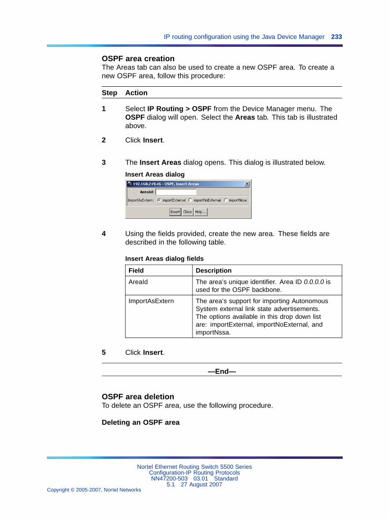
IP routing configuration using the Java Device Manager 233
OSPF area creationThe Areas tab can also be used to create a new OSPF area. To create anew OSPF area, follow this procedure:
Step Action
1 Select IP Routing > OSPF from the Device Manager menu. TheOSPF dialog will open. Select the Areas tab. This tab is illustratedabove.
2 Click Insert.
3 The Insert Areas dialog opens. This dialog is illustrated below.
Insert Areas dialog
4 Using the fields provided, create the new area. These fields aredescribed in the following table.
Insert Areas dialog fields
Field Description
AreaId The area’s unique identifier. Area ID 0.0.0.0 isused for the OSPF backbone.
ImportAsExtern The area’s support for importing AutonomousSystem external link state advertisements.The options available in this drop down listare: importExternal, importNoExternal, andimportNssa.
5 Click Insert.
—End—
OSPF area deletionTo delete an OSPF area, use the following procedure.
Deleting an OSPF area
Nortel Ethernet Routing Switch 5500 SeriesConfiguration-IP Routing ProtocolsNN47200-503 03.01 Standard
5.1 27 August 2007Copyright © 2005-2007, Nortel Networks
.
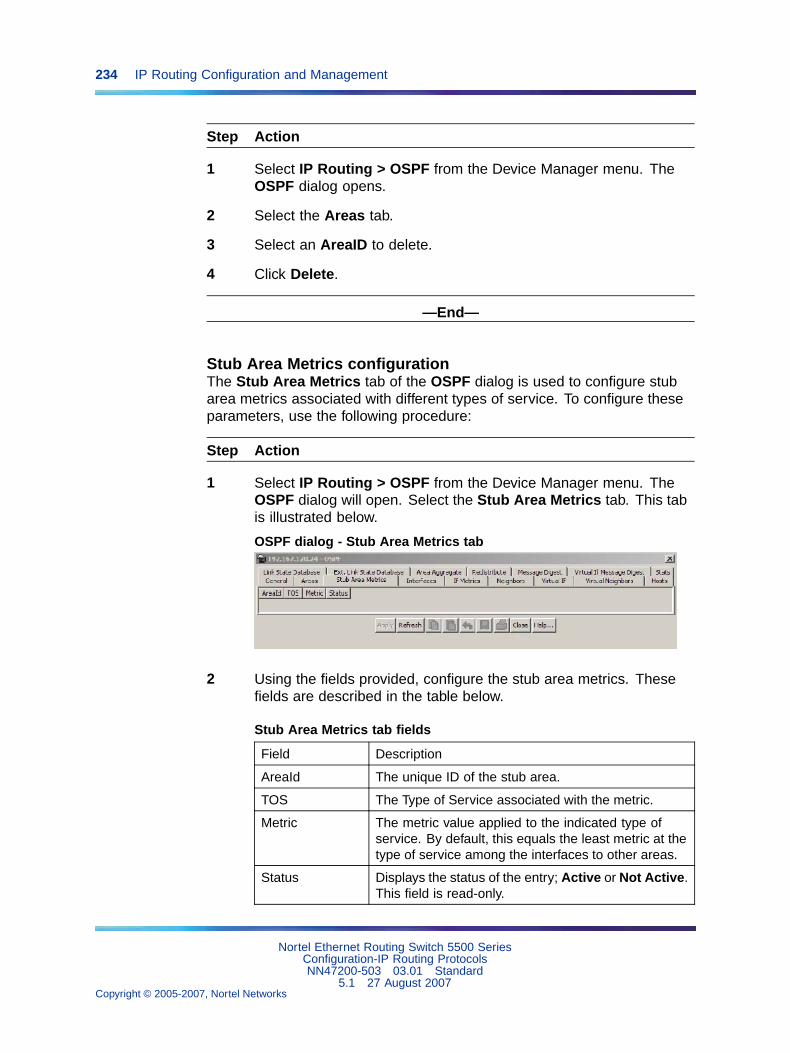
234 IP Routing Configuration and Management
Step Action
1 Select IP Routing > OSPF from the Device Manager menu. TheOSPF dialog opens.
2 Select the Areas tab.
3 Select an AreaID to delete.
4 Click Delete.
—End—
Stub Area Metrics configurationThe Stub Area Metrics tab of the OSPF dialog is used to configure stubarea metrics associated with different types of service. To configure theseparameters, use the following procedure:
Step Action
1 Select IP Routing > OSPF from the Device Manager menu. TheOSPF dialog will open. Select the Stub Area Metrics tab. This tabis illustrated below.
OSPF dialog - Stub Area Metrics tab
2 Using the fields provided, configure the stub area metrics. Thesefields are described in the table below.
Stub Area Metrics tab fields
Field Description
AreaId The unique ID of the stub area.
TOS The Type of Service associated with the metric.
Metric The metric value applied to the indicated type ofservice. By default, this equals the least metric at thetype of service among the interfaces to other areas.
Status Displays the status of the entry; Active or Not Active.This field is read-only.
Nortel Ethernet Routing Switch 5500 SeriesConfiguration-IP Routing ProtocolsNN47200-503 03.01 Standard
5.1 27 August 2007Copyright © 2005-2007, Nortel Networks
.
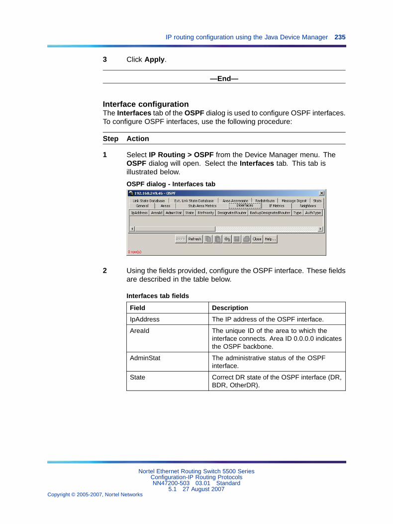
IP routing configuration using the Java Device Manager 235
3 Click Apply.
—End—
Interface configurationThe Interfaces tab of the OSPF dialog is used to configure OSPF interfaces.To configure OSPF interfaces, use the following procedure:
Step Action
1 Select IP Routing > OSPF from the Device Manager menu. TheOSPF dialog will open. Select the Interfaces tab. This tab isillustrated below.
OSPF dialog - Interfaces tab
2 Using the fields provided, configure the OSPF interface. These fieldsare described in the table below.
Interfaces tab fields
Field Description
IpAddress The IP address of the OSPF interface.
AreaId The unique ID of the area to which theinterface connects. Area ID 0.0.0.0 indicatesthe OSPF backbone.
AdminStat The administrative status of the OSPFinterface.
State Correct DR state of the OSPF interface (DR,BDR, OtherDR).
Nortel Ethernet Routing Switch 5500 SeriesConfiguration-IP Routing ProtocolsNN47200-503 03.01 Standard
5.1 27 August 2007Copyright © 2005-2007, Nortel Networks
.
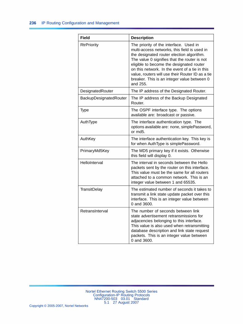
236 IP Routing Configuration and Management
Field Description
RtrPriority The priority of the interface. Used inmulti-access networks, this field is used inthe designated router election algorithm.The value 0 signifies that the router is noteligible to become the designated routeron this network. In the event of a tie in thisvalue, routers will use their Router ID as a tiebreaker. This is an integer value between 0and 255.
DesignatedRouter The IP address of the Designated Router.
BackupDesignatedRouter The IP address of the Backup DesignatedRouter.
Type The OSPF interface type. The optionsavailable are: broadcast or passive.
AuthType The interface authentication type. Theoptions available are: none, simplePassword,or md5.
AuthKey The interface authentication key. This key isfor when AuthType is simplePassword.
PrimaryMd5Key The MD5 primary key if it exists. Otherwisethis field will display 0.
HelloInterval The interval in seconds between the Hellopackets sent by the router on this interface.This value must be the same for all routersattached to a common network. This is aninteger value between 1 and 65535.
TransitDelay The estimated number of seconds it takes totransmit a link state update packet over thisinterface. This is an integer value between0 and 3600.
RetransInterval The number of seconds between linkstate advertisement retransmissions foradjacencies belonging to this interface.This value is also used when retransmittingdatabase description and link state requestpackets. This is an integer value between0 and 3600.
Nortel Ethernet Routing Switch 5500 SeriesConfiguration-IP Routing ProtocolsNN47200-503 03.01 Standard
5.1 27 August 2007Copyright © 2005-2007, Nortel Networks
.
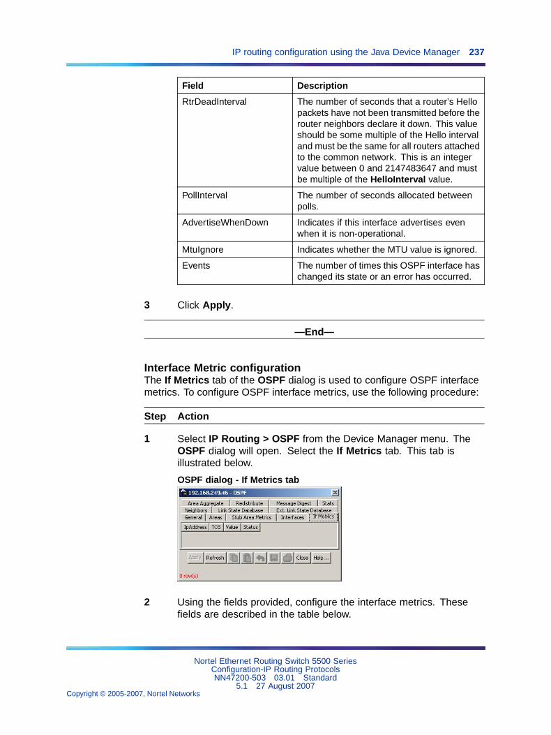
IP routing configuration using the Java Device Manager 237
Field Description
RtrDeadInterval The number of seconds that a router’s Hellopackets have not been transmitted before therouter neighbors declare it down. This valueshould be some multiple of the Hello intervaland must be the same for all routers attachedto the common network. This is an integervalue between 0 and 2147483647 and mustbe multiple of the HelloInterval value.
PollInterval The number of seconds allocated betweenpolls.
AdvertiseWhenDown Indicates if this interface advertises evenwhen it is non-operational.
MtuIgnore Indicates whether the MTU value is ignored.
Events The number of times this OSPF interface haschanged its state or an error has occurred.
3 Click Apply.
—End—
Interface Metric configurationThe If Metrics tab of the OSPF dialog is used to configure OSPF interfacemetrics. To configure OSPF interface metrics, use the following procedure:
Step Action
1 Select IP Routing > OSPF from the Device Manager menu. TheOSPF dialog will open. Select the If Metrics tab. This tab isillustrated below.
OSPF dialog - If Metrics tab
2 Using the fields provided, configure the interface metrics. Thesefields are described in the table below.
Nortel Ethernet Routing Switch 5500 SeriesConfiguration-IP Routing ProtocolsNN47200-503 03.01 Standard
5.1 27 August 2007Copyright © 2005-2007, Nortel Networks
.
238 IP Routing Configuration and Management
If Metrics tab fields
Field Description
IpAddress The IP address of the interface.
TOS The Type of Service associated with the metric.
Value The value advertized to other areas indicating thedistance from the OSPF router to any network in therange. This is an integer value between 0 and 65535.
Status Displays the status of the entry; Active or Not Active.This field is read-only.
3 Click Apply.
—End—
Neighbor informationThe Neighbors tab of the OSPF dialog is used to view OSPF neighborinformation. To view OSPF neighbors, use the following procedure:
Step Action
1 Select IP Routing > OSPF from the Device Manager menu. TheOSPF dialog will open. Select the Neighbors tab. This tab isillustrated below.
OSPF dialog - Neighbors tab
2 Using the fields provided, view the OSPF neighbor information.These fields are explained in the table below.
Nortel Ethernet Routing Switch 5500 SeriesConfiguration-IP Routing ProtocolsNN47200-503 03.01 Standard
5.1 27 August 2007Copyright © 2005-2007, Nortel Networks
.
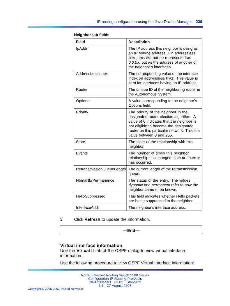
IP routing configuration using the Java Device Manager 239
Neighbor tab fields
Field Description
IpAddr The IP address this neighbor is using asan IP source address. On addresslesslinks, this will not be represented as0.0.0.0 but as the address of another ofthe neighbor’s interfaces.
AddressLessIndex The corresponding value of the interfaceindex on addressless links. This value iszero for interfaces having an IP address.
Router The unique ID of the neighboring router inthe Autonomous System.
Options A value corresponding to the neighbor’sOptions field.
Priority The priority of the neighbor in thedesignated router election algorithm. Avalue of 0 indicates that the neighbor isnot eligible to become the designatedrouter on this particular network. This is avalue between 0 and 255.
State The state of the relationship with thisneighbor.
Events The number of times this neighborrelationship has changed state or an errorhas occurred.
RetransmissionQueueLength The current length of the retransmissionqueue.
NbmaNbrPermanence The status of the entry. The valuesdynamic and permanent refer to how theneighbor came to be known.
HelloSuppressed This field indicates whether Hello packetsare being suppressed to the neighbor.
InterfaceAddr The neighbor’s interface address.
3 Click Refresh to update the information.
—End—
Virtual interface informationUse the Virtual If tab of the OSPF dialog to view virtual interfaceinformation.
Use the following procedure to view OSPF Virtual Interface information:
Nortel Ethernet Routing Switch 5500 SeriesConfiguration-IP Routing ProtocolsNN47200-503 03.01 Standard
5.1 27 August 2007Copyright © 2005-2007, Nortel Networks
.
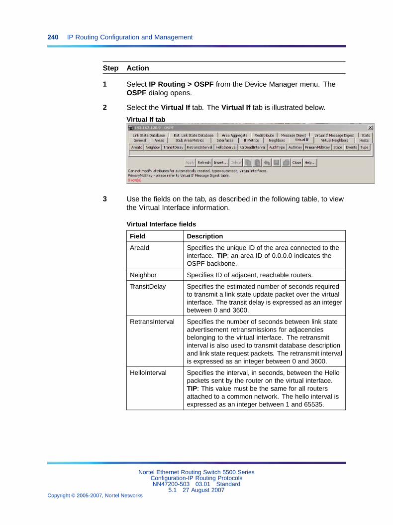
240 IP Routing Configuration and Management
Step Action
1 Select IP Routing > OSPF from the Device Manager menu. TheOSPF dialog opens.
2 Select the Virtual If tab. The Virtual If tab is illustrated below.
Virtual If tab
3 Use the fields on the tab, as described in the following table, to viewthe Virtual Interface information.
Virtual Interface fields
Field Description
AreaId Specifies the unique ID of the area connected to theinterface. TIP: an area ID of 0.0.0.0 indicates theOSPF backbone.
Neighbor Specifies ID of adjacent, reachable routers.
TransitDelay Specifies the estimated number of seconds requiredto transmit a link state update packet over the virtualinterface. The transit delay is expressed as an integerbetween 0 and 3600.
RetransInterval Specifies the number of seconds between link stateadvertisement retransmissions for adjacenciesbelonging to the virtual interface. The retransmitinterval is also used to transmit database descriptionand link state request packets. The retransmit intervalis expressed as an integer between 0 and 3600.
HelloInterval Specifies the interval, in seconds, between the Hellopackets sent by the router on the virtual interface.TIP: This value must be the same for all routersattached to a common network. The hello interval isexpressed as an integer between 1 and 65535.
Nortel Ethernet Routing Switch 5500 SeriesConfiguration-IP Routing ProtocolsNN47200-503 03.01 Standard
5.1 27 August 2007Copyright © 2005-2007, Nortel Networks
.
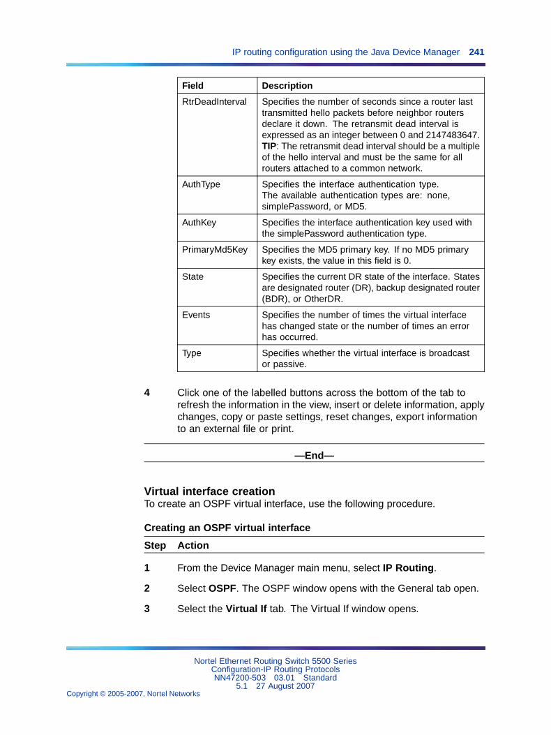
IP routing configuration using the Java Device Manager 241
Field Description
RtrDeadInterval Specifies the number of seconds since a router lasttransmitted hello packets before neighbor routersdeclare it down. The retransmit dead interval isexpressed as an integer between 0 and 2147483647.TIP: The retransmit dead interval should be a multipleof the hello interval and must be the same for allrouters attached to a common network.
AuthType Specifies the interface authentication type.The available authentication types are: none,simplePassword, or MD5.
AuthKey Specifies the interface authentication key used withthe simplePassword authentication type.
PrimaryMd5Key Specifies the MD5 primary key. If no MD5 primarykey exists, the value in this field is 0.
State Specifies the current DR state of the interface. Statesare designated router (DR), backup designated router(BDR), or OtherDR.
Events Specifies the number of times the virtual interfacehas changed state or the number of times an errorhas occurred.
Type Specifies whether the virtual interface is broadcastor passive.
4 Click one of the labelled buttons across the bottom of the tab torefresh the information in the view, insert or delete information, applychanges, copy or paste settings, reset changes, export informationto an external file or print.
—End—
Virtual interface creationTo create an OSPF virtual interface, use the following procedure.
Creating an OSPF virtual interface
Step Action
1 From the Device Manager main menu, select IP Routing.
2 Select OSPF. The OSPF window opens with the General tab open.
3 Select the Virtual If tab. The Virtual If window opens.
Nortel Ethernet Routing Switch 5500 SeriesConfiguration-IP Routing ProtocolsNN47200-503 03.01 Standard
5.1 27 August 2007Copyright © 2005-2007, Nortel Networks
.
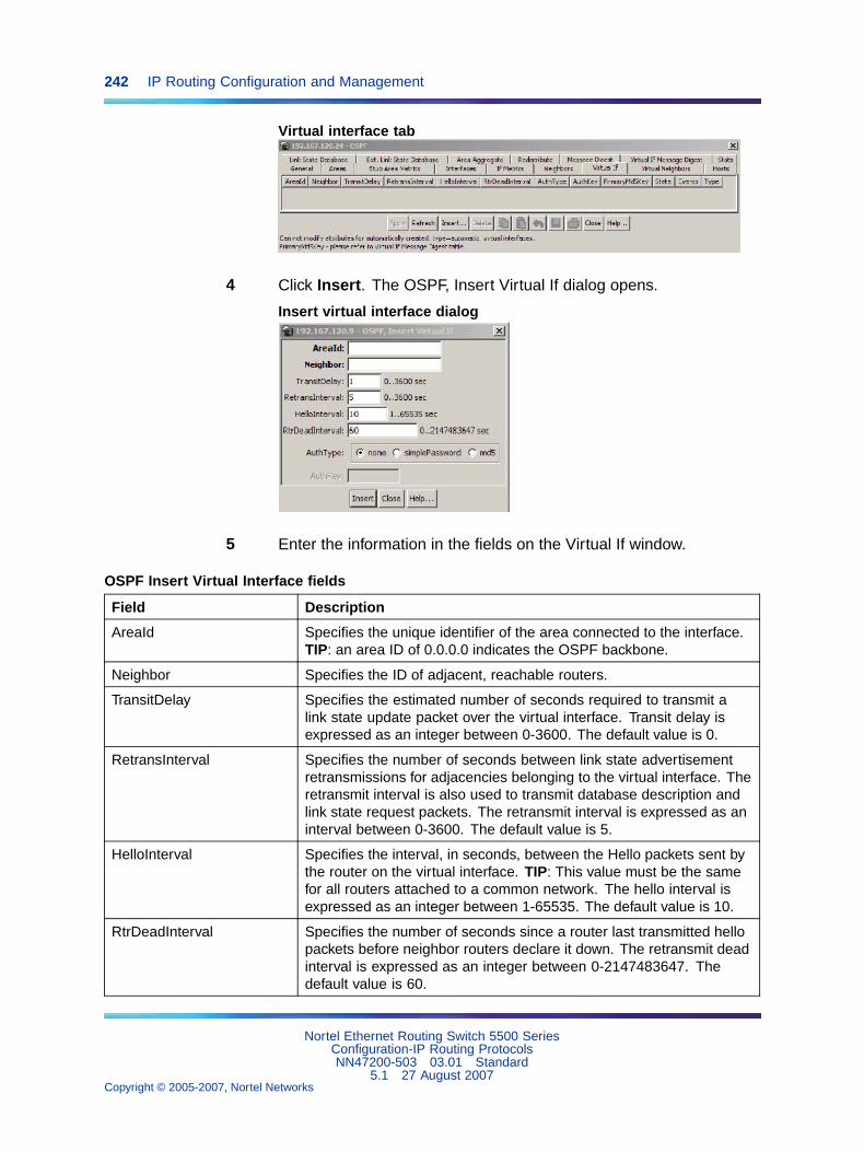
242 IP Routing Configuration and Management
Virtual interface tab
4 Click Insert. The OSPF, Insert Virtual If dialog opens.
Insert virtual interface dialog
5 Enter the information in the fields on the Virtual If window.
OSPF Insert Virtual Interface fields
Field Description
AreaId Specifies the unique identifier of the area connected to the interface.TIP: an area ID of 0.0.0.0 indicates the OSPF backbone.
Neighbor Specifies the ID of adjacent, reachable routers.
TransitDelay Specifies the estimated number of seconds required to transmit alink state update packet over the virtual interface. Transit delay isexpressed as an integer between 0-3600. The default value is 0.
RetransInterval Specifies the number of seconds between link state advertisementretransmissions for adjacencies belonging to the virtual interface. Theretransmit interval is also used to transmit database description andlink state request packets. The retransmit interval is expressed as aninterval between 0-3600. The default value is 5.
HelloInterval Specifies the interval, in seconds, between the Hello packets sent bythe router on the virtual interface. TIP: This value must be the samefor all routers attached to a common network. The hello interval isexpressed as an integer between 1-65535. The default value is 10.
RtrDeadInterval Specifies the number of seconds since a router last transmitted hellopackets before neighbor routers declare it down. The retransmit deadinterval is expressed as an integer between 0-2147483647. Thedefault value is 60.
Nortel Ethernet Routing Switch 5500 SeriesConfiguration-IP Routing ProtocolsNN47200-503 03.01 Standard
5.1 27 August 2007Copyright © 2005-2007, Nortel Networks
.
IP routing configuration using the Java Device Manager 243
Field Description
AuthType Specifies the interface authentication type. The availableauthentication types are: none, simple password, or MD5. If youselect simplePassword, you must supply an authorization key.
AuthKey Specifies the interface authentication key used with thesimplePassword authentication type.
6 Click Insert.
—End—
Virtual interface deletionTo delete an OSPF virtual interface, use the following procedure.
Deleting an OSPF virtual interface
Step Action
1 From the Device Manager main menu, select IP Routing.
2 Select OSPF. The OSPF window opens.
3 Select the Virtual If tab.
4 Select an AreaId to delete.
5 Click Delete.
—End—
Automatic Virtual Link creationUse the AutoVirtLinkEnable box on the OSPF General tab to create anautomatic virtual link. For more information about Virtual Link, see "OSPFvirtual link" (page 31).
Use the following procedure to create an automatic Virtual Link.
Creating an automatic Virtual Link
Step Action
1 From the Device Manager main menu, select IP Routing > OSPF.The OSPF dialog opens.
2 On the General tab, enter the router ID in the RouterId box for oneof the end point ABRs.
Nortel Ethernet Routing Switch 5500 SeriesConfiguration-IP Routing ProtocolsNN47200-503 03.01 Standard
5.1 27 August 2007Copyright © 2005-2007, Nortel Networks
.
244 IP Routing Configuration and Management
3 Check the AutoVirtLinkEnable box.
4 Click Apply.
5 Enter the router ID in the RouterId box for the other end point ABR.
6 Check the AutoVirtLinkEnable box.
7 Click Apply.
—End—
Automatic Virtual Link DeletionTo delete an automatic Virtual Link use the following procedure.
Deleting an automatic Virtual Link
Step Action
1 From the Device Manager main menu, select IP Routing > OSPF.The OSPF dialog opens.
2 On the General tab, enter the router ID in the RouterId box for oneof the end point ABRs.
3 Deselect the AutoVirtLinkEnable box.
4 Click Apply.
5 Enter the router ID in the RouterId box for the other end point ABR.
6 Deselect the AutoVirtLinkEnable box.
7 Click Apply.
—End—
Automatic Virtual Links are also removed when the transit area is deleted orwhen the router is no longer an ABR.
Virtual neighbors informationUse the Virtual Neighbors tab of the OSPF dialog to view virtual neighborinformation.
Use the following procedure to view OSPF Virtual Neighbors information:
Nortel Ethernet Routing Switch 5500 SeriesConfiguration-IP Routing ProtocolsNN47200-503 03.01 Standard
5.1 27 August 2007Copyright © 2005-2007, Nortel Networks
.
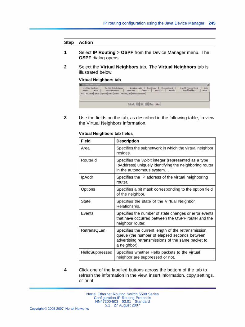
IP routing configuration using the Java Device Manager 245
Step Action
1 Select IP Routing > OSPF from the Device Manager menu. TheOSPF dialog opens.
2 Select the Virtual Neighbors tab. The Virtual Neighbors tab isillustrated below.
Virtual Neighbors tab
3 Use the fields on the tab, as described in the following table, to viewthe Virtual Neighbors information.
Virtual Neighbors tab fields
Field Description
Area Specifies the subnetwork in which the virtual neighborresides.
RouterId Specifies the 32-bit integer (represented as a typeIpAddress) uniquely identifying the neighboring routerin the autonomous system. .
IpAddr Specifies the IP address of the virtual neighboringrouter.
Options Specifies a bit mask corresponding to the option fieldof the neighbor.
State Specifies the state of the Virtual NeighborRelationship.
Events Specifies the number of state changes or error eventsthat have occurred between the OSPF router and theneighbor router.
RetransQLen Specifies the current length of the retransmissionqueue (the number of elapsed seconds betweenadvertising retransmissions of the same packet toa neighbor).
HelloSuppressed Specifies whether Hello packets to the virtualneighbor are suppressed or not.
4 Click one of the labelled buttons across the bottom of the tab torefresh the information in the view, insert information, copy settings,or print.
Nortel Ethernet Routing Switch 5500 SeriesConfiguration-IP Routing ProtocolsNN47200-503 03.01 Standard
5.1 27 August 2007Copyright © 2005-2007, Nortel Networks
.
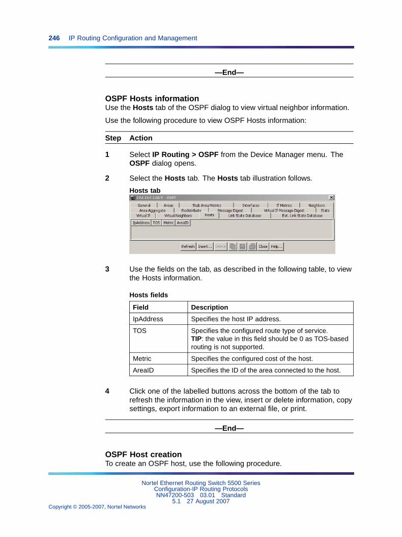
246 IP Routing Configuration and Management
—End—
OSPF Hosts informationUse the Hosts tab of the OSPF dialog to view virtual neighbor information.
Use the following procedure to view OSPF Hosts information:
Step Action
1 Select IP Routing > OSPF from the Device Manager menu. TheOSPF dialog opens.
2 Select the Hosts tab. The Hosts tab illustration follows.
Hosts tab
3 Use the fields on the tab, as described in the following table, to viewthe Hosts information.
Hosts fields
Field Description
IpAddress Specifies the host IP address.
TOS Specifies the configured route type of service.TIP: the value in this field should be 0 as TOS-basedrouting is not supported.
Metric Specifies the configured cost of the host.
AreaID Specifies the ID of the area connected to the host.
4 Click one of the labelled buttons across the bottom of the tab torefresh the information in the view, insert or delete information, copysettings, export information to an external file, or print.
—End—
OSPF Host creationTo create an OSPF host, use the following procedure.
Nortel Ethernet Routing Switch 5500 SeriesConfiguration-IP Routing ProtocolsNN47200-503 03.01 Standard
5.1 27 August 2007Copyright © 2005-2007, Nortel Networks
.
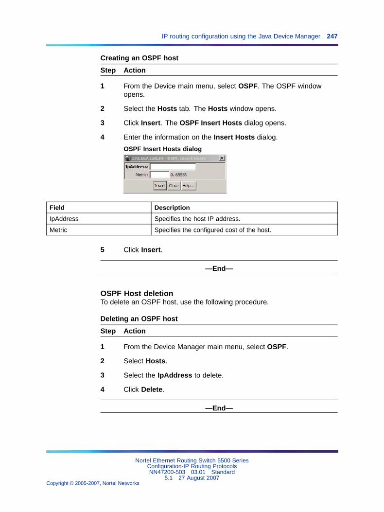
IP routing configuration using the Java Device Manager 247
Creating an OSPF host
Step Action
1 From the Device main menu, select OSPF. The OSPF windowopens.
2 Select the Hosts tab. The Hosts window opens.
3 Click Insert. The OSPF Insert Hosts dialog opens.
4 Enter the information on the Insert Hosts dialog.
OSPF Insert Hosts dialog
Field Description
IpAddress Specifies the host IP address.
Metric Specifies the configured cost of the host.
5 Click Insert.
—End—
OSPF Host deletionTo delete an OSPF host, use the following procedure.
Deleting an OSPF host
Step Action
1 From the Device Manager main menu, select OSPF.
2 Select Hosts.
3 Select the IpAddress to delete.
4 Click Delete.
—End—
Nortel Ethernet Routing Switch 5500 SeriesConfiguration-IP Routing ProtocolsNN47200-503 03.01 Standard
5.1 27 August 2007Copyright © 2005-2007, Nortel Networks
.
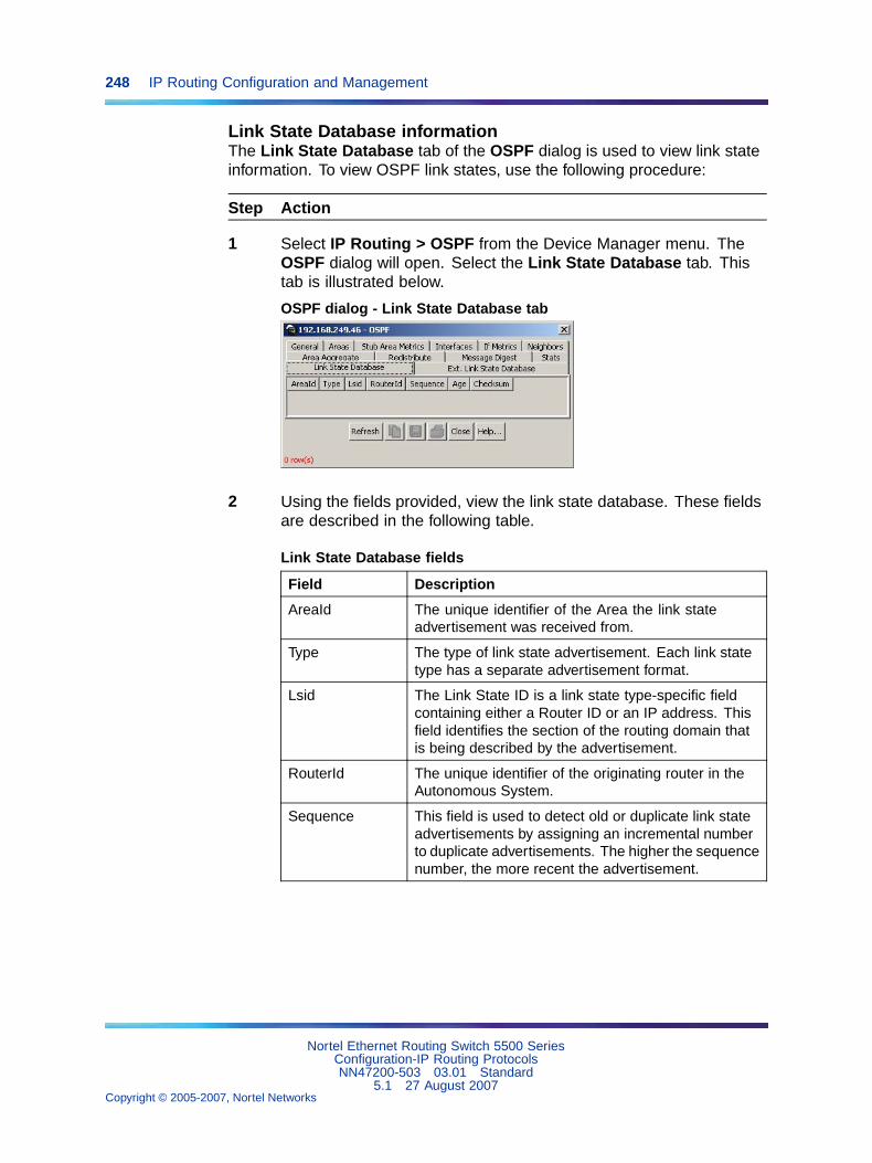
248 IP Routing Configuration and Management
Link State Database informationThe Link State Database tab of the OSPF dialog is used to view link stateinformation. To view OSPF link states, use the following procedure:
Step Action
1 Select IP Routing > OSPF from the Device Manager menu. TheOSPF dialog will open. Select the Link State Database tab. Thistab is illustrated below.
OSPF dialog - Link State Database tab
2 Using the fields provided, view the link state database. These fieldsare described in the following table.
Link State Database fields
Field Description
AreaId The unique identifier of the Area the link stateadvertisement was received from.
Type The type of link state advertisement. Each link statetype has a separate advertisement format.
Lsid The Link State ID is a link state type-specific fieldcontaining either a Router ID or an IP address. Thisfield identifies the section of the routing domain thatis being described by the advertisement.
RouterId The unique identifier of the originating router in theAutonomous System.
Sequence This field is used to detect old or duplicate link stateadvertisements by assigning an incremental numberto duplicate advertisements. The higher the sequencenumber, the more recent the advertisement.
Nortel Ethernet Routing Switch 5500 SeriesConfiguration-IP Routing ProtocolsNN47200-503 03.01 Standard
5.1 27 August 2007Copyright © 2005-2007, Nortel Networks
.
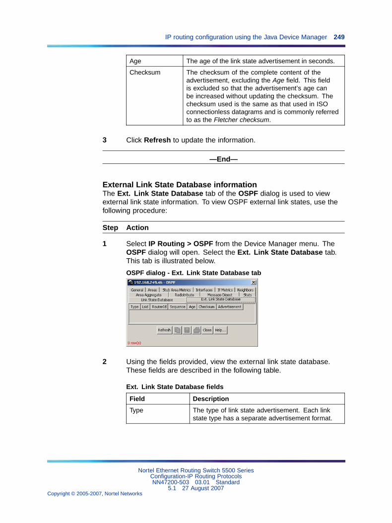
IP routing configuration using the Java Device Manager 249
Age The age of the link state advertisement in seconds.
Checksum The checksum of the complete content of theadvertisement, excluding the Age field. This fieldis excluded so that the advertisement’s age canbe increased without updating the checksum. Thechecksum used is the same as that used in ISOconnectionless datagrams and is commonly referredto as the Fletcher checksum.
3 Click Refresh to update the information.
—End—
External Link State Database informationThe Ext. Link State Database tab of the OSPF dialog is used to viewexternal link state information. To view OSPF external link states, use thefollowing procedure:
Step Action
1 Select IP Routing > OSPF from the Device Manager menu. TheOSPF dialog will open. Select the Ext. Link State Database tab.This tab is illustrated below.
OSPF dialog - Ext. Link State Database tab
2 Using the fields provided, view the external link state database.These fields are described in the following table.
Ext. Link State Database fields
Field Description
Type The type of link state advertisement. Each linkstate type has a separate advertisement format.
Nortel Ethernet Routing Switch 5500 SeriesConfiguration-IP Routing ProtocolsNN47200-503 03.01 Standard
5.1 27 August 2007Copyright © 2005-2007, Nortel Networks
.
250 IP Routing Configuration and Management
Lsid The Link State ID is a link state type-specific fieldcontaining either a Router ID or an IP address. Thisfield identifies the section of the routing domain thatis being described by the advertisement.
RouterId The unique identifier of the originating router in theAutonomous System.
Sequence This field is used to detect old or duplicate linkstate advertisements by assigning an incrementalnumber to duplicate advertisements. The higherthe sequence number, the more recent theadvertisement.
Age The age of the link state advertisement in seconds.
Checksum The checksum of the complete content of theadvertisement, excluding the Age field. This fieldis excluded so that the advertisement’s age canbe increased without updating the checksum.The checksum used is the same as that used inISO connectionless datagrams and is commonlyreferred to as the Fletcher checksum.
Advertisement The entire link state advertisement including theheader."
3 Click Refresh to update the information.
—End—
Area Aggregate configurationThe Area Aggregate tab of the OSPF dialog is used to configure areaaggregate information. To configure OSPF area aggregates, use thefollowing procedure:
Step Action
1 Select IP Routing > OSPF from the Device Manager menu. TheOSPF dialog will open. Select the Area Aggregate tab. This tabis illustrated below.
Nortel Ethernet Routing Switch 5500 SeriesConfiguration-IP Routing ProtocolsNN47200-503 03.01 Standard
5.1 27 August 2007Copyright © 2005-2007, Nortel Networks
.
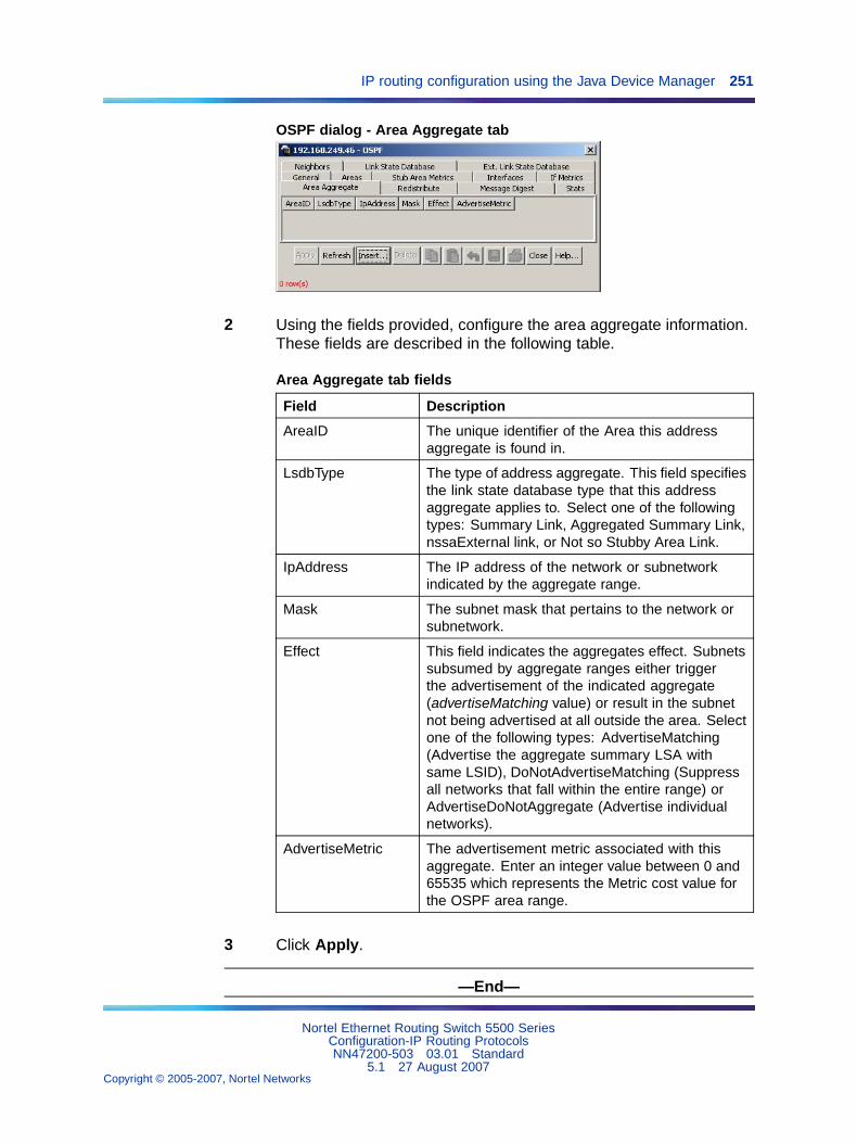
IP routing configuration using the Java Device Manager 251
OSPF dialog - Area Aggregate tab
2 Using the fields provided, configure the area aggregate information.These fields are described in the following table.
Area Aggregate tab fields
Field Description
AreaID The unique identifier of the Area this addressaggregate is found in.
LsdbType The type of address aggregate. This field specifiesthe link state database type that this addressaggregate applies to. Select one of the followingtypes: Summary Link, Aggregated Summary Link,nssaExternal link, or Not so Stubby Area Link.
IpAddress The IP address of the network or subnetworkindicated by the aggregate range.
Mask The subnet mask that pertains to the network orsubnetwork.
Effect This field indicates the aggregates effect. Subnetssubsumed by aggregate ranges either triggerthe advertisement of the indicated aggregate(advertiseMatching value) or result in the subnetnot being advertised at all outside the area. Selectone of the following types: AdvertiseMatching(Advertise the aggregate summary LSA withsame LSID), DoNotAdvertiseMatching (Suppressall networks that fall within the entire range) orAdvertiseDoNotAggregate (Advertise individualnetworks).
AdvertiseMetric The advertisement metric associated with thisaggregate. Enter an integer value between 0 and65535 which represents the Metric cost value forthe OSPF area range.
3 Click Apply.
—End—
Nortel Ethernet Routing Switch 5500 SeriesConfiguration-IP Routing ProtocolsNN47200-503 03.01 Standard
5.1 27 August 2007Copyright © 2005-2007, Nortel Networks
.
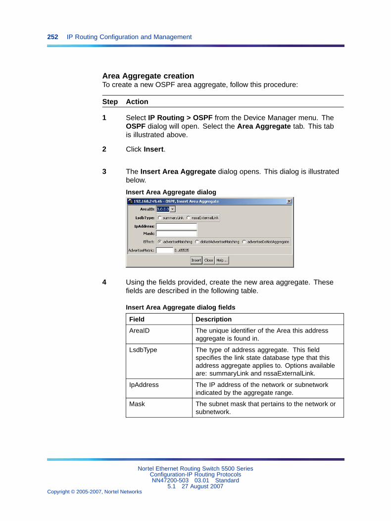
252 IP Routing Configuration and Management
Area Aggregate creationTo create a new OSPF area aggregate, follow this procedure:
Step Action
1 Select IP Routing > OSPF from the Device Manager menu. TheOSPF dialog will open. Select the Area Aggregate tab. This tabis illustrated above.
2 Click Insert.
3 The Insert Area Aggregate dialog opens. This dialog is illustratedbelow.
Insert Area Aggregate dialog
4 Using the fields provided, create the new area aggregate. Thesefields are described in the following table.
Insert Area Aggregate dialog fields
Field Description
AreaID The unique identifier of the Area this addressaggregate is found in.
LsdbType The type of address aggregate. This fieldspecifies the link state database type that thisaddress aggregate applies to. Options availableare: summaryLink and nssaExternalLink.
IpAddress The IP address of the network or subnetworkindicated by the aggregate range.
Mask The subnet mask that pertains to the network orsubnetwork.
Nortel Ethernet Routing Switch 5500 SeriesConfiguration-IP Routing ProtocolsNN47200-503 03.01 Standard
5.1 27 August 2007Copyright © 2005-2007, Nortel Networks
.
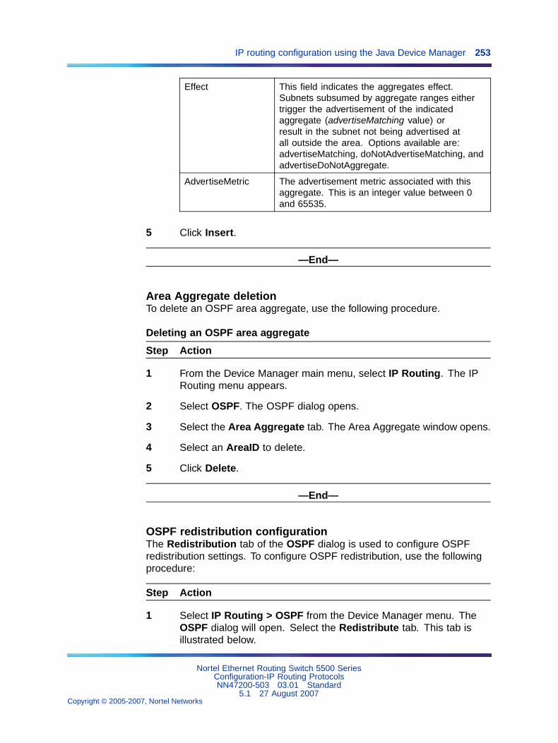
IP routing configuration using the Java Device Manager 253
Effect This field indicates the aggregates effect.Subnets subsumed by aggregate ranges eithertrigger the advertisement of the indicatedaggregate (advertiseMatching value) orresult in the subnet not being advertised atall outside the area. Options available are:advertiseMatching, doNotAdvertiseMatching, andadvertiseDoNotAggregate.
AdvertiseMetric The advertisement metric associated with thisaggregate. This is an integer value between 0and 65535.
5 Click Insert.
—End—
Area Aggregate deletionTo delete an OSPF area aggregate, use the following procedure.
Deleting an OSPF area aggregate
Step Action
1 From the Device Manager main menu, select IP Routing. The IPRouting menu appears.
2 Select OSPF. The OSPF dialog opens.
3 Select the Area Aggregate tab. The Area Aggregate window opens.
4 Select an AreaID to delete.
5 Click Delete.
—End—
OSPF redistribution configurationThe Redistribution tab of the OSPF dialog is used to configure OSPFredistribution settings. To configure OSPF redistribution, use the followingprocedure:
Step Action
1 Select IP Routing > OSPF from the Device Manager menu. TheOSPF dialog will open. Select the Redistribute tab. This tab isillustrated below.
Nortel Ethernet Routing Switch 5500 SeriesConfiguration-IP Routing ProtocolsNN47200-503 03.01 Standard
5.1 27 August 2007Copyright © 2005-2007, Nortel Networks
.
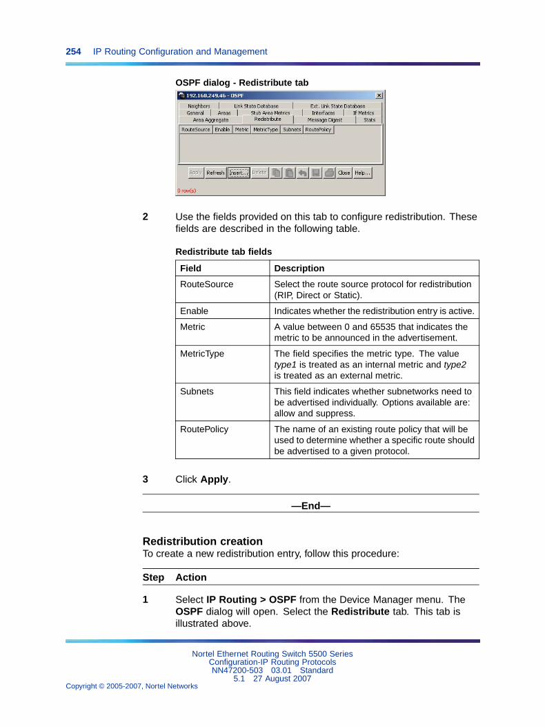
254 IP Routing Configuration and Management
OSPF dialog - Redistribute tab
2 Use the fields provided on this tab to configure redistribution. Thesefields are described in the following table.
Redistribute tab fields
Field Description
RouteSource Select the route source protocol for redistribution(RIP, Direct or Static).
Enable Indicates whether the redistribution entry is active.
Metric A value between 0 and 65535 that indicates themetric to be announced in the advertisement.
MetricType The field specifies the metric type. The valuetype1 is treated as an internal metric and type2is treated as an external metric.
Subnets This field indicates whether subnetworks need tobe advertised individually. Options available are:allow and suppress.
RoutePolicy The name of an existing route policy that will beused to determine whether a specific route shouldbe advertised to a given protocol.
3 Click Apply.
—End—
Redistribution creationTo create a new redistribution entry, follow this procedure:
Step Action
1 Select IP Routing > OSPF from the Device Manager menu. TheOSPF dialog will open. Select the Redistribute tab. This tab isillustrated above.
Nortel Ethernet Routing Switch 5500 SeriesConfiguration-IP Routing ProtocolsNN47200-503 03.01 Standard
5.1 27 August 2007Copyright © 2005-2007, Nortel Networks
.
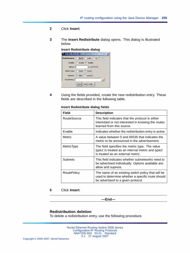
IP routing configuration using the Java Device Manager 255
2 Click Insert.
3 The Insert Redistribute dialog opens. This dialog is illustratedbelow.
Insert Redistribute dialog
4 Using the fields provided, create the new redistribution entry. Thesefields are described in the following table.
Insert Redistribute dialog fields
Field Description
RouteSource This field indicates that the protocol is eitherinterested or not interested in knowing the routeslearned from this source.
Enable Indicates whether the redistribution entry is active.
Metric A value between 0 and 65535 that indicates themetric to be announced in the advertisement.
MetricType The field specifies the metric type. The valuetype1 is treated as an internal metric and type2is treated as an external metric.
Subnets This field indicates whether subnetworks need tobe advertised individually. Options available are:allow and supress.
RoutePolicy The name of an existing switch policy that will beused to determine whether a specific route shouldbe advertised to a given protocol.
5 Click Insert.
—End—
Redistribution deletionTo delete a redistribution entry, use the following procedure.
Nortel Ethernet Routing Switch 5500 SeriesConfiguration-IP Routing ProtocolsNN47200-503 03.01 Standard
5.1 27 August 2007Copyright © 2005-2007, Nortel Networks
.
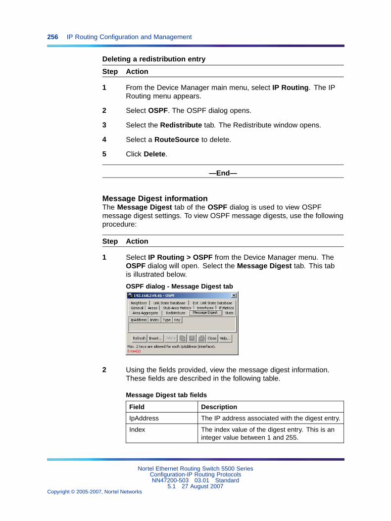
256 IP Routing Configuration and Management
Deleting a redistribution entry
Step Action
1 From the Device Manager main menu, select IP Routing. The IPRouting menu appears.
2 Select OSPF. The OSPF dialog opens.
3 Select the Redistribute tab. The Redistribute window opens.
4 Select a RouteSource to delete.
5 Click Delete.
—End—
Message Digest informationThe Message Digest tab of the OSPF dialog is used to view OSPFmessage digest settings. To view OSPF message digests, use the followingprocedure:
Step Action
1 Select IP Routing > OSPF from the Device Manager menu. TheOSPF dialog will open. Select the Message Digest tab. This tabis illustrated below.
OSPF dialog - Message Digest tab
2 Using the fields provided, view the message digest information.These fields are described in the following table.
Message Digest tab fields
Field Description
IpAddress The IP address associated with the digest entry.
Index The index value of the digest entry. This is aninteger value between 1 and 255.
Nortel Ethernet Routing Switch 5500 SeriesConfiguration-IP Routing ProtocolsNN47200-503 03.01 Standard
5.1 27 August 2007Copyright © 2005-2007, Nortel Networks
.
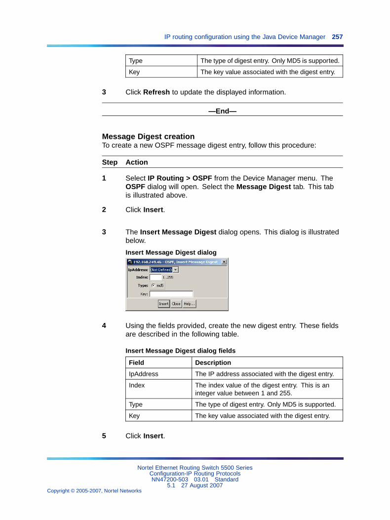
IP routing configuration using the Java Device Manager 257
Type The type of digest entry. Only MD5 is supported.
Key The key value associated with the digest entry.
3 Click Refresh to update the displayed information.
—End—
Message Digest creationTo create a new OSPF message digest entry, follow this procedure:
Step Action
1 Select IP Routing > OSPF from the Device Manager menu. TheOSPF dialog will open. Select the Message Digest tab. This tabis illustrated above.
2 Click Insert.
3 The Insert Message Digest dialog opens. This dialog is illustratedbelow.
Insert Message Digest dialog
4 Using the fields provided, create the new digest entry. These fieldsare described in the following table.
Insert Message Digest dialog fields
Field Description
IpAddress The IP address associated with the digest entry.
Index The index value of the digest entry. This is aninteger value between 1 and 255.
Type The type of digest entry. Only MD5 is supported.
Key The key value associated with the digest entry.
5 Click Insert.
Nortel Ethernet Routing Switch 5500 SeriesConfiguration-IP Routing ProtocolsNN47200-503 03.01 Standard
5.1 27 August 2007Copyright © 2005-2007, Nortel Networks
.
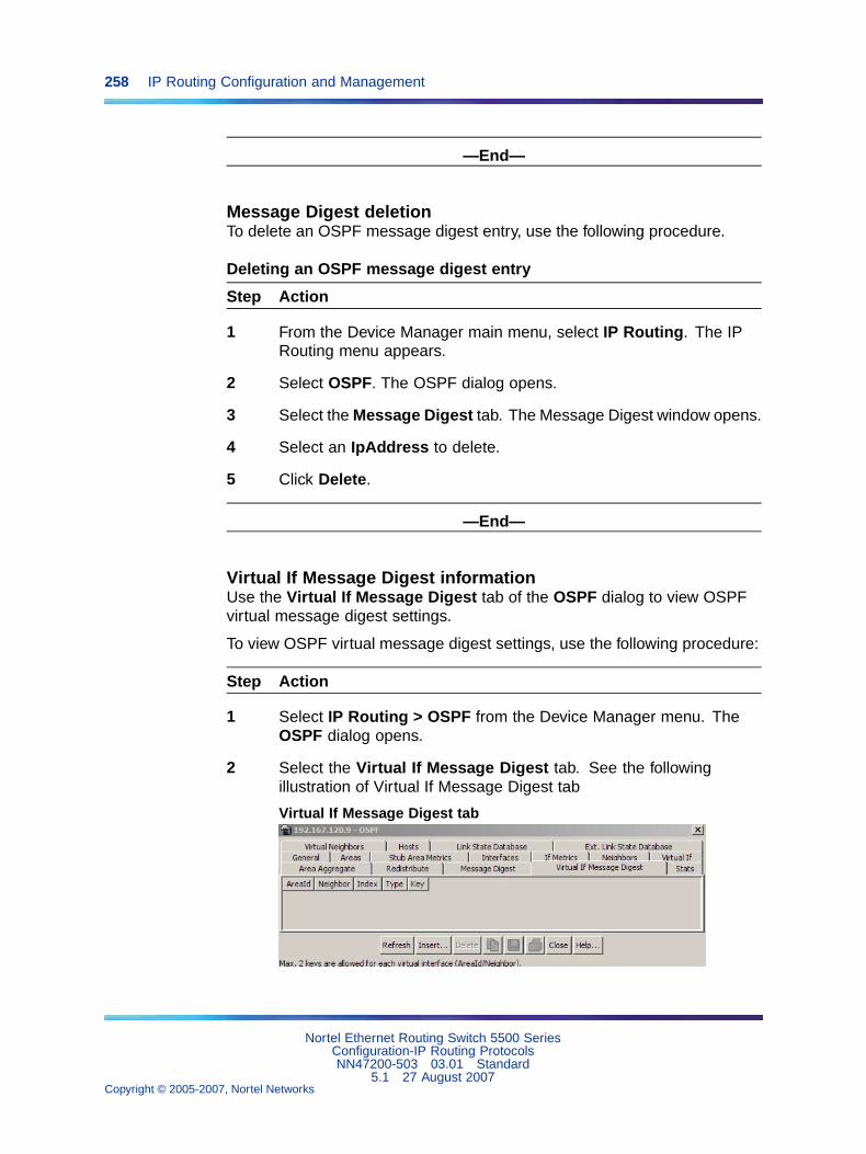
258 IP Routing Configuration and Management
—End—
Message Digest deletionTo delete an OSPF message digest entry, use the following procedure.
Deleting an OSPF message digest entry
Step Action
1 From the Device Manager main menu, select IP Routing. The IPRouting menu appears.
2 Select OSPF. The OSPF dialog opens.
3 Select the Message Digest tab. The Message Digest window opens.
4 Select an IpAddress to delete.
5 Click Delete.
—End—
Virtual If Message Digest informationUse the Virtual If Message Digest tab of the OSPF dialog to view OSPFvirtual message digest settings.
To view OSPF virtual message digest settings, use the following procedure:
Step Action
1 Select IP Routing > OSPF from the Device Manager menu. TheOSPF dialog opens.
2 Select the Virtual If Message Digest tab. See the followingillustration of Virtual If Message Digest tab
Virtual If Message Digest tab
Nortel Ethernet Routing Switch 5500 SeriesConfiguration-IP Routing ProtocolsNN47200-503 03.01 Standard
5.1 27 August 2007Copyright © 2005-2007, Nortel Networks
.
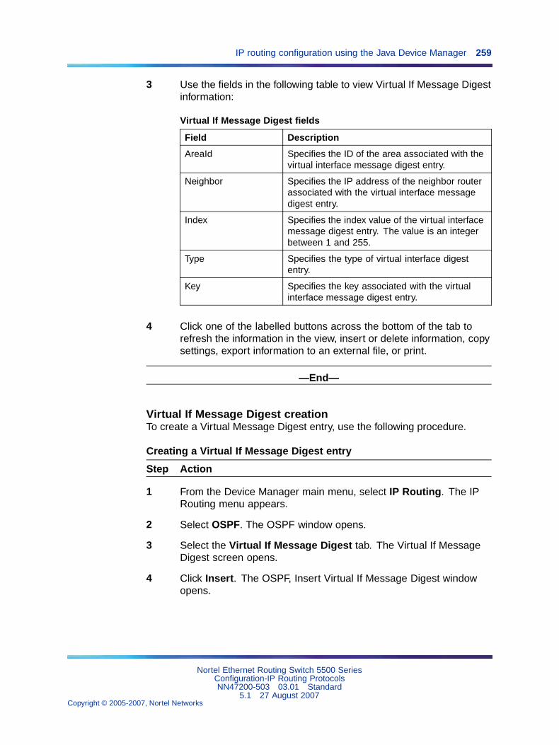
IP routing configuration using the Java Device Manager 259
3 Use the fields in the following table to view Virtual If Message Digestinformation:
Virtual If Message Digest fields
Field Description
AreaId Specifies the ID of the area associated with thevirtual interface message digest entry.
Neighbor Specifies the IP address of the neighbor routerassociated with the virtual interface messagedigest entry.
Index Specifies the index value of the virtual interfacemessage digest entry. The value is an integerbetween 1 and 255.
Type Specifies the type of virtual interface digestentry.
Key Specifies the key associated with the virtualinterface message digest entry.
4 Click one of the labelled buttons across the bottom of the tab torefresh the information in the view, insert or delete information, copysettings, export information to an external file, or print.
—End—
Virtual If Message Digest creationTo create a Virtual Message Digest entry, use the following procedure.
Creating a Virtual If Message Digest entry
Step Action
1 From the Device Manager main menu, select IP Routing. The IPRouting menu appears.
2 Select OSPF. The OSPF window opens.
3 Select the Virtual If Message Digest tab. The Virtual If MessageDigest screen opens.
4 Click Insert. The OSPF, Insert Virtual If Message Digest windowopens.
Nortel Ethernet Routing Switch 5500 SeriesConfiguration-IP Routing ProtocolsNN47200-503 03.01 Standard
5.1 27 August 2007Copyright © 2005-2007, Nortel Networks
.
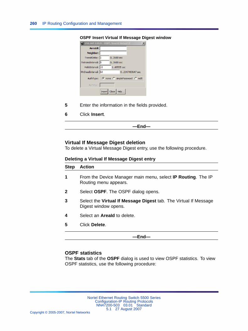
260 IP Routing Configuration and Management
OSPF Insert Virtual If Message Digest window
5 Enter the information in the fields provided.
6 Click Insert.
—End—
Virtual If Message Digest deletionTo delete a Virtual Message Digest entry, use the following procedure.
Deleting a Virtual If Message Digest entry
Step Action
1 From the Device Manager main menu, select IP Routing. The IPRouting menu appears.
2 Select OSPF. The OSPF dialog opens.
3 Select the Virtual If Message Digest tab. The Virtual If MessageDigest window opens.
4 Select an AreaId to delete.
5 Click Delete.
—End—
OSPF statisticsThe Stats tab of the OSPF dialog is used to view OSPF statistics. To viewOSPF statistics, use the following procedure:
Nortel Ethernet Routing Switch 5500 SeriesConfiguration-IP Routing ProtocolsNN47200-503 03.01 Standard
5.1 27 August 2007Copyright © 2005-2007, Nortel Networks
.
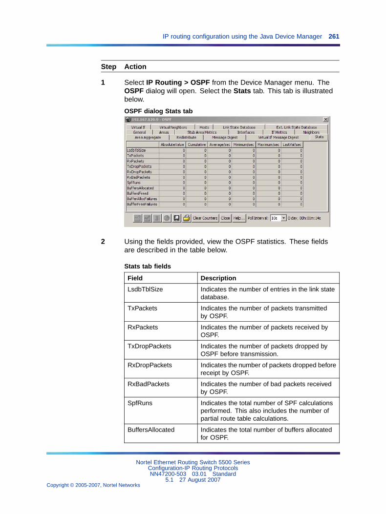
IP routing configuration using the Java Device Manager 261
Step Action
1 Select IP Routing > OSPF from the Device Manager menu. TheOSPF dialog will open. Select the Stats tab. This tab is illustratedbelow.
OSPF dialog Stats tab
2 Using the fields provided, view the OSPF statistics. These fieldsare described in the table below.
Stats tab fields
Field Description
LsdbTblSize Indicates the number of entries in the link statedatabase.
TxPackets Indicates the number of packets transmittedby OSPF.
RxPackets Indicates the number of packets received byOSPF.
TxDropPackets Indicates the number of packets dropped byOSPF before transmission.
RxDropPackets Indicates the number of packets dropped beforereceipt by OSPF.
RxBadPackets Indicates the number of bad packets receivedby OSPF.
SpfRuns Indicates the total number of SPF calculationsperformed. This also includes the number ofpartial route table calculations.
BuffersAllocated Indicates the total number of buffers allocatedfor OSPF.
Nortel Ethernet Routing Switch 5500 SeriesConfiguration-IP Routing ProtocolsNN47200-503 03.01 Standard
5.1 27 August 2007Copyright © 2005-2007, Nortel Networks
.
262 IP Routing Configuration and Management
BuffersFreed Indicates the total number of buffers that arefreed by OSPF.
BufferAllocFailures Indicates the number of times that OSPF hasfailed to allocate buffers.
BufferFreeFailures Indicates the number of times that OSPF hasfailed to allocate buffers.
3 Values on the Stats tab will refresh automatically based on the valueselected in the Poll Interval field. To clear the counters and startover at zero, click Clear Counters.
—End—
VLAN OSPF statisticsOSPF statistical information can also be viewed on a per-interface basis. Toview VLAN OSPF statistics, perform the following procedure:
Step Action
1 Select VLAN > VLANs from the Device Manager menu. The VLANdialog opens.
2 Select an interface from those listed on the Basic tab.
3 Click the IP button.
4 On the IP VLAN dialog, select the OSPF Stats tab. This tab isillustrated below.
Nortel Ethernet Routing Switch 5500 SeriesConfiguration-IP Routing ProtocolsNN47200-503 03.01 Standard
5.1 27 August 2007Copyright © 2005-2007, Nortel Networks
.
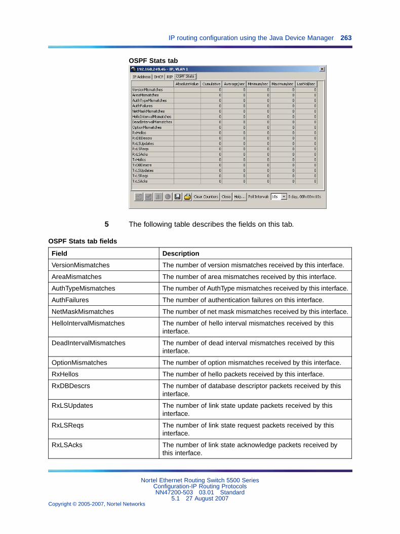
IP routing configuration using the Java Device Manager 263
OSPF Stats tab
5 The following table describes the fields on this tab.
OSPF Stats tab fields
Field Description
VersionMismatches The number of version mismatches received by this interface.
AreaMismatches The number of area mismatches received by this interface.
AuthTypeMismatches The number of AuthType mismatches received by this interface.
AuthFailures The number of authentication failures on this interface.
NetMaskMismatches The number of net mask mismatches received by this interface.
HelloIntervalMismatches The number of hello interval mismatches received by thisinterface.
DeadIntervalMismatches The number of dead interval mismatches received by thisinterface.
OptionMismatches The number of option mismatches received by this interface.
RxHellos The number of hello packets received by this interface.
RxDBDescrs The number of database descriptor packets received by thisinterface.
RxLSUpdates The number of link state update packets received by thisinterface.
RxLSReqs The number of link state request packets received by thisinterface.
RxLSAcks The number of link state acknowledge packets received bythis interface.
Nortel Ethernet Routing Switch 5500 SeriesConfiguration-IP Routing ProtocolsNN47200-503 03.01 Standard
5.1 27 August 2007Copyright © 2005-2007, Nortel Networks
.
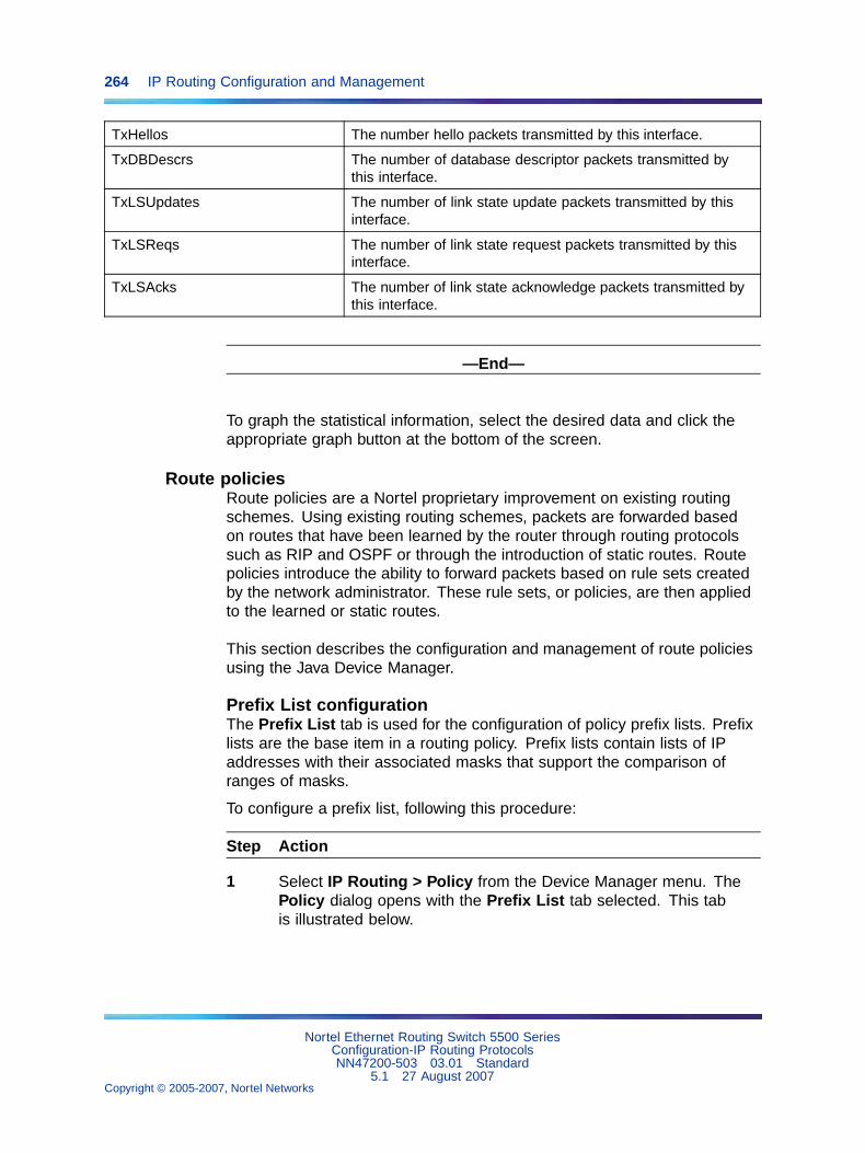
264 IP Routing Configuration and Management
TxHellos The number hello packets transmitted by this interface.
TxDBDescrs The number of database descriptor packets transmitted bythis interface.
TxLSUpdates The number of link state update packets transmitted by thisinterface.
TxLSReqs The number of link state request packets transmitted by thisinterface.
TxLSAcks The number of link state acknowledge packets transmitted bythis interface.
—End—
To graph the statistical information, select the desired data and click theappropriate graph button at the bottom of the screen.
Route policiesRoute policies are a Nortel proprietary improvement on existing routingschemes. Using existing routing schemes, packets are forwarded basedon routes that have been learned by the router through routing protocolssuch as RIP and OSPF or through the introduction of static routes. Routepolicies introduce the ability to forward packets based on rule sets createdby the network administrator. These rule sets, or policies, are then appliedto the learned or static routes.
This section describes the configuration and management of route policiesusing the Java Device Manager.
Prefix List configurationThe Prefix List tab is used for the configuration of policy prefix lists. Prefixlists are the base item in a routing policy. Prefix lists contain lists of IPaddresses with their associated masks that support the comparison ofranges of masks.
To configure a prefix list, following this procedure:
Step Action
1 Select IP Routing > Policy from the Device Manager menu. ThePolicy dialog opens with the Prefix List tab selected. This tabis illustrated below.
Nortel Ethernet Routing Switch 5500 SeriesConfiguration-IP Routing ProtocolsNN47200-503 03.01 Standard
5.1 27 August 2007Copyright © 2005-2007, Nortel Networks
.
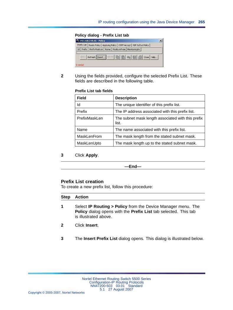
IP routing configuration using the Java Device Manager 265
Policy dialog - Prefix List tab
2 Using the fields provided, configure the selected Prefix List. Thesefields are described in the following table.
Prefix List tab fields
Field Description
Id The unique identifier of this prefix list.
Prefix The IP address associated with this prefix list.
PrefixMaskLen The subnet mask length associated with this prefixlist.
Name The name associated with this prefix list.
MaskLenFrom The mask length from the stated subnet mask.
MaskLenUpto The mask length up to the stated subnet mask.
3 Click Apply.
—End—
Prefix List creationTo create a new prefix list, follow this procedure:
Step Action
1 Select IP Routing > Policy from the Device Manager menu. ThePolicy dialog opens with the Prefix List tab selected. This tabis illustrated above.
2 Click Insert.
3 The Insert Prefix List dialog opens. This dialog is illustrated below.
Nortel Ethernet Routing Switch 5500 SeriesConfiguration-IP Routing ProtocolsNN47200-503 03.01 Standard
5.1 27 August 2007Copyright © 2005-2007, Nortel Networks
.
266 IP Routing Configuration and Management
Insert Prefix List dialog
4 Using the fields provided, create a new prefix list. These fields aredescribed in the following table.
Insert Prefix List dialog fields
Field Description
Id The unique identifier of this prefix list.
Prefix The IP address associated with this prefix list.
PrefixMaskLen The subnet mask length associated with this prefixlist.
Name The name associated with this prefix list.
MaskLenFrom The mask length from the stated subnet mask.
MaskLenUpto The mask length up to the stated subnet mask.
5 Click Insert.
—End—
Prefix List deletionTo delete a prefix list, use the following procedure.
Deleting a Prefix List
Step Action
1 Select IP Routing > Policy from the Device Manager menu. ThePolicy dialog opens with the Prefix List tab selected.
2 Select an Id to delete.
3 Click Delete.
—End—
Nortel Ethernet Routing Switch 5500 SeriesConfiguration-IP Routing ProtocolsNN47200-503 03.01 Standard
5.1 27 August 2007Copyright © 2005-2007, Nortel Networks
.
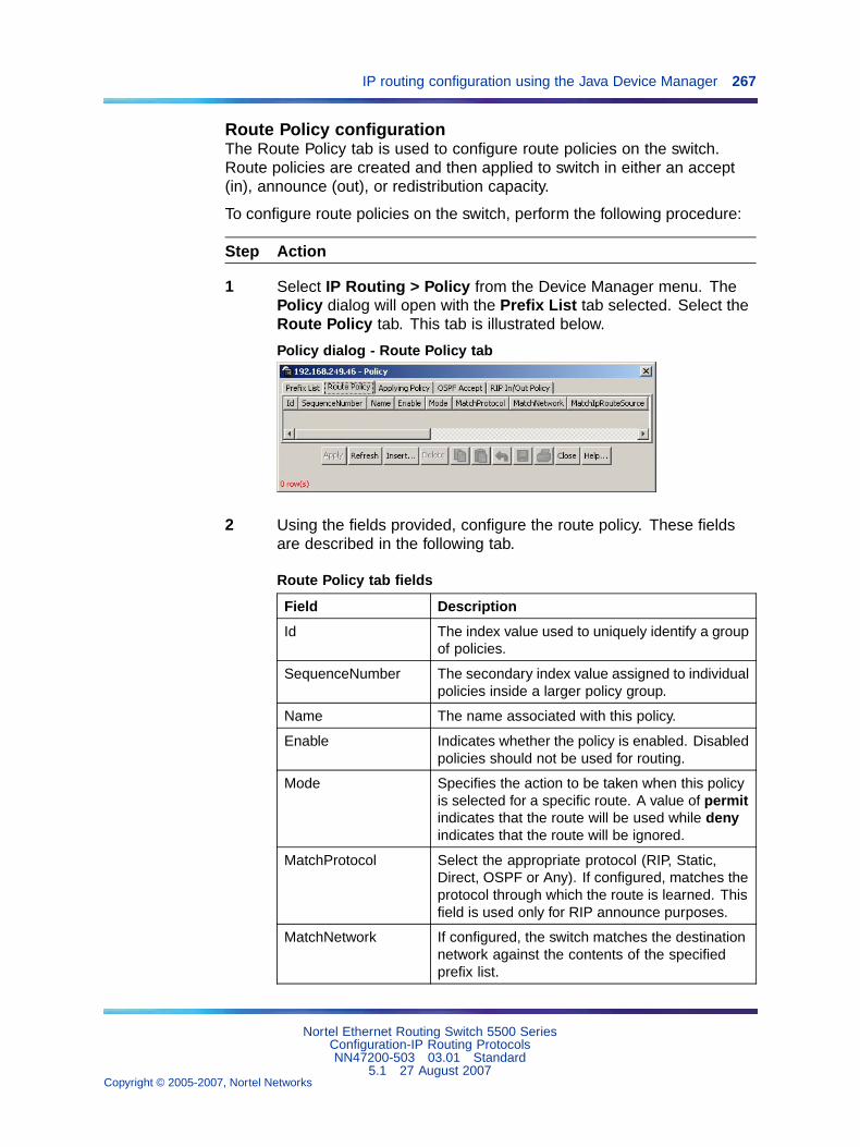
IP routing configuration using the Java Device Manager 267
Route Policy configurationThe Route Policy tab is used to configure route policies on the switch.Route policies are created and then applied to switch in either an accept(in), announce (out), or redistribution capacity.
To configure route policies on the switch, perform the following procedure:
Step Action
1 Select IP Routing > Policy from the Device Manager menu. ThePolicy dialog will open with the Prefix List tab selected. Select theRoute Policy tab. This tab is illustrated below.
Policy dialog - Route Policy tab
2 Using the fields provided, configure the route policy. These fieldsare described in the following tab.
Route Policy tab fields
Field Description
Id The index value used to uniquely identify a groupof policies.
SequenceNumber The secondary index value assigned to individualpolicies inside a larger policy group.
Name The name associated with this policy.
Enable Indicates whether the policy is enabled. Disabledpolicies should not be used for routing.
Mode Specifies the action to be taken when this policyis selected for a specific route. A value of permitindicates that the route will be used while denyindicates that the route will be ignored.
MatchProtocol Select the appropriate protocol (RIP, Static,Direct, OSPF or Any). If configured, matches theprotocol through which the route is learned. Thisfield is used only for RIP announce purposes.
MatchNetwork If configured, the switch matches the destinationnetwork against the contents of the specifiedprefix list.
Nortel Ethernet Routing Switch 5500 SeriesConfiguration-IP Routing ProtocolsNN47200-503 03.01 Standard
5.1 27 August 2007Copyright © 2005-2007, Nortel Networks
.
268 IP Routing Configuration and Management
MatchIpRouteSource If configured, matches the next hop IP addressfor RIP routes and advertising router IDsfor OSPF routes against the contents of thespecified prefix list. This option is ignored for allother route types.
MatchNextHop If configured, matches the next hop IP addressof the route against the contents of the specifiedprefix list. This field applies only to non-localroutes.
MatchInterface If configured, the switch matches the IP addressof the interface by which the RIP route waslearned against the contents of the specifiedprefix list. This field is used only for RIP routesand ignored for all other type of route.
MatchRouteType Sets a specific route-type to be matched (appliesonly to OSPF routes). Externaltype1, andExternaltype2 specify the OSPF routes of thespecified type only. OSPF internal refers to intra-and inter-area routes.
MatchMetric If configured, the switch matches the metric ofthe incoming advertisement or existing routeagainst the specified value (1 to 655535). If 0,then this field is ignored. The default is 0.
NssaPbit Set or reset the P bit in specified type 7 LSA. Bydefault the P bit is always set in case the user setit to a disable state for a particular route policythan all type 7. LSAs associated with that routepolicy will have the P bit cleared with this intactNSSA ABR will not perform translation of theseLSAs to type 5. Default is enabled.
SetRoutePreference Setting the preference greater than zero,specifies the route preference value to beassigned to the routes which matches this policy.This applies to Accept policies only. You can seta value from 0 to 255. The default value is 0. Ifthe default is configured, the global preferencevalue is used.
SetMetric If configured, the switch sets the metric valuefor the route while announcing or redistributing.The default-import-metric is 0. If the defaultis configured, the original cost of the route isadvertised into OSPF; for RIP, the original cost ofthe route or the default value is used.
Nortel Ethernet Routing Switch 5500 SeriesConfiguration-IP Routing ProtocolsNN47200-503 03.01 Standard
5.1 27 August 2007Copyright © 2005-2007, Nortel Networks
.
IP routing configuration using the Java Device Manager 269
SetMetricType Applicable to OSPF protocol only. If configured,sets the metric type for the routes to beannounced into the OSPF routing protocol thatmatches this policy. The default is type 2. Thisfield is applicable only for OSPF announcepolicies.
SetInjectNetList If configured, the switch replaces the destinationnetwork of the route that matches this policy withthe contents of the specified prefix list.
SetMask Indicates the mask to used for routes that passthe policy matching criteria.
3 Click Apply.
—End—
Route Policy creationTo create a new route policy, follow this procedure:
Step Action
1 Select IP Routing > Policy from the Device Manager menu. ThePolicy dialog will open with the Prefix List tab selected. Select theRoute Policy tab. This tab is illustrated above.
2 Click Insert.
3 The Insert Route Policy dialog opens. This dialog is illustratedbelow.
Nortel Ethernet Routing Switch 5500 SeriesConfiguration-IP Routing ProtocolsNN47200-503 03.01 Standard
5.1 27 August 2007Copyright © 2005-2007, Nortel Networks
.
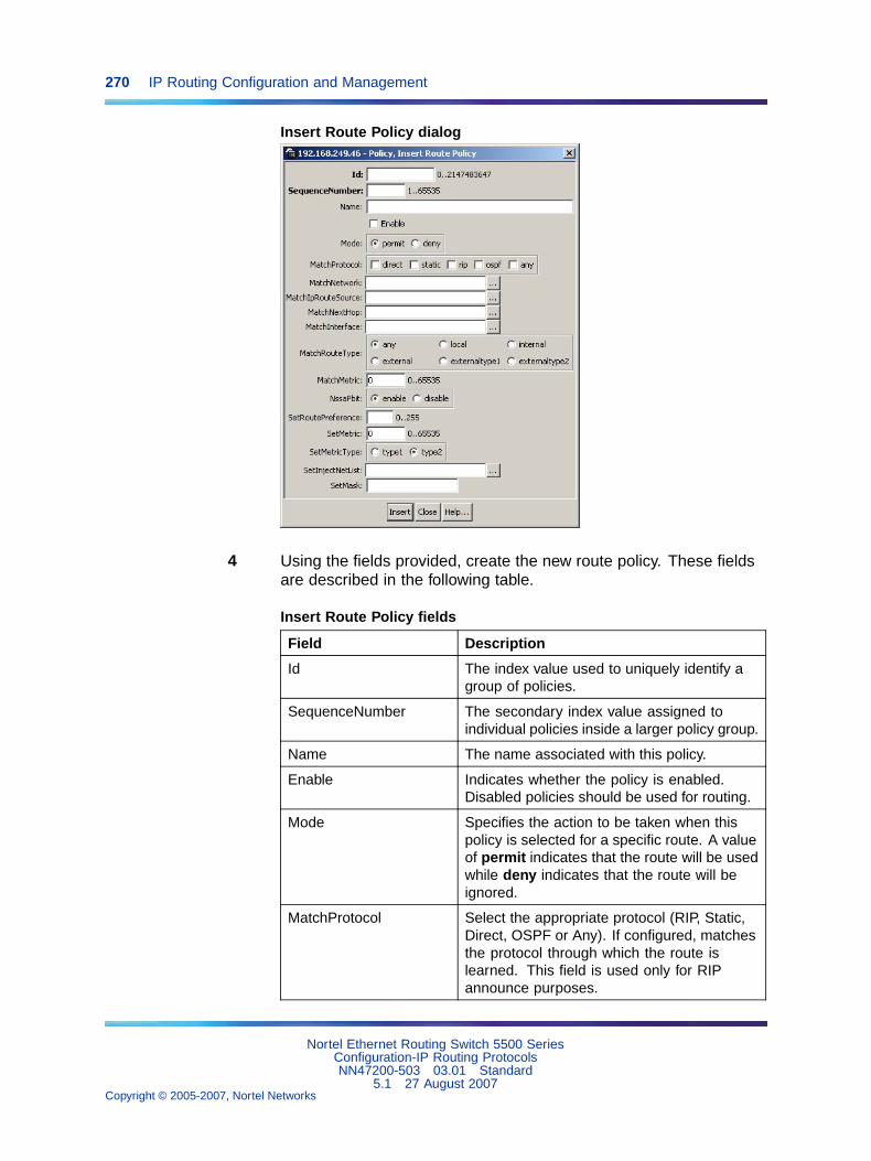
270 IP Routing Configuration and Management
Insert Route Policy dialog
4 Using the fields provided, create the new route policy. These fieldsare described in the following table.
Insert Route Policy fields
Field Description
Id The index value used to uniquely identify agroup of policies.
SequenceNumber The secondary index value assigned toindividual policies inside a larger policy group.
Name The name associated with this policy.
Enable Indicates whether the policy is enabled.Disabled policies should be used for routing.
Mode Specifies the action to be taken when thispolicy is selected for a specific route. A valueof permit indicates that the route will be usedwhile deny indicates that the route will beignored.
MatchProtocol Select the appropriate protocol (RIP, Static,Direct, OSPF or Any). If configured, matchesthe protocol through which the route islearned. This field is used only for RIPannounce purposes.
Nortel Ethernet Routing Switch 5500 SeriesConfiguration-IP Routing ProtocolsNN47200-503 03.01 Standard
5.1 27 August 2007Copyright © 2005-2007, Nortel Networks
.
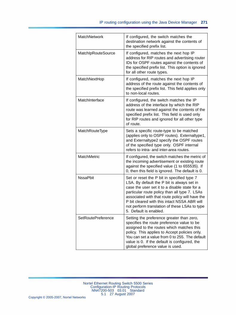
IP routing configuration using the Java Device Manager 271
MatchNetwork If configured, the switch matches thedestination network against the contents ofthe specified prefix list.
MatchIpRouteSource If configured, matches the next hop IPaddress for RIP routes and advertising routerIDs for OSPF routes against the contents ofthe specified prefix list. This option is ignoredfor all other route types.
MatchNextHop If configured, matches the next hop IPaddress of the route against the contents ofthe specified prefix list. This field applies onlyto non-local routes.
MatchInterface If configured, the switch matches the IPaddress of the interface by which the RIProute was learned against the contents of thespecified prefix list. This field is used onlyfor RIP routes and ignored for all other typeof route.
MatchRouteType Sets a specific route-type to be matched(applies only to OSPF routes). Externaltype1,and Externaltype2 specify the OSPF routesof the specified type only. OSPF internalrefers to intra- and inter-area routes.
MatchMetric If configured, the switch matches the metric ofthe incoming advertisement or existing routeagainst the specified value (1 to 655535). If0, then this field is ignored. The default is 0.
NssaPbit Set or reset the P bit in specified type 7LSA. By default the P bit is always set incase the user set it to a disable state for aparticular route policy than all type 7. LSAsassociated with that route policy will have theP bit cleared with this intact NSSA ABR willnot perform translation of these LSAs to type5. Default is enabled.
SetRoutePreference Setting the preference greater than zero,specifies the route preference value to beassigned to the routes which matches thispolicy. This applies to Accept policies only.You can set a value from 0 to 255. The defaultvalue is 0. If the default is configured, theglobal preference value is used.
Nortel Ethernet Routing Switch 5500 SeriesConfiguration-IP Routing ProtocolsNN47200-503 03.01 Standard
5.1 27 August 2007Copyright © 2005-2007, Nortel Networks
.
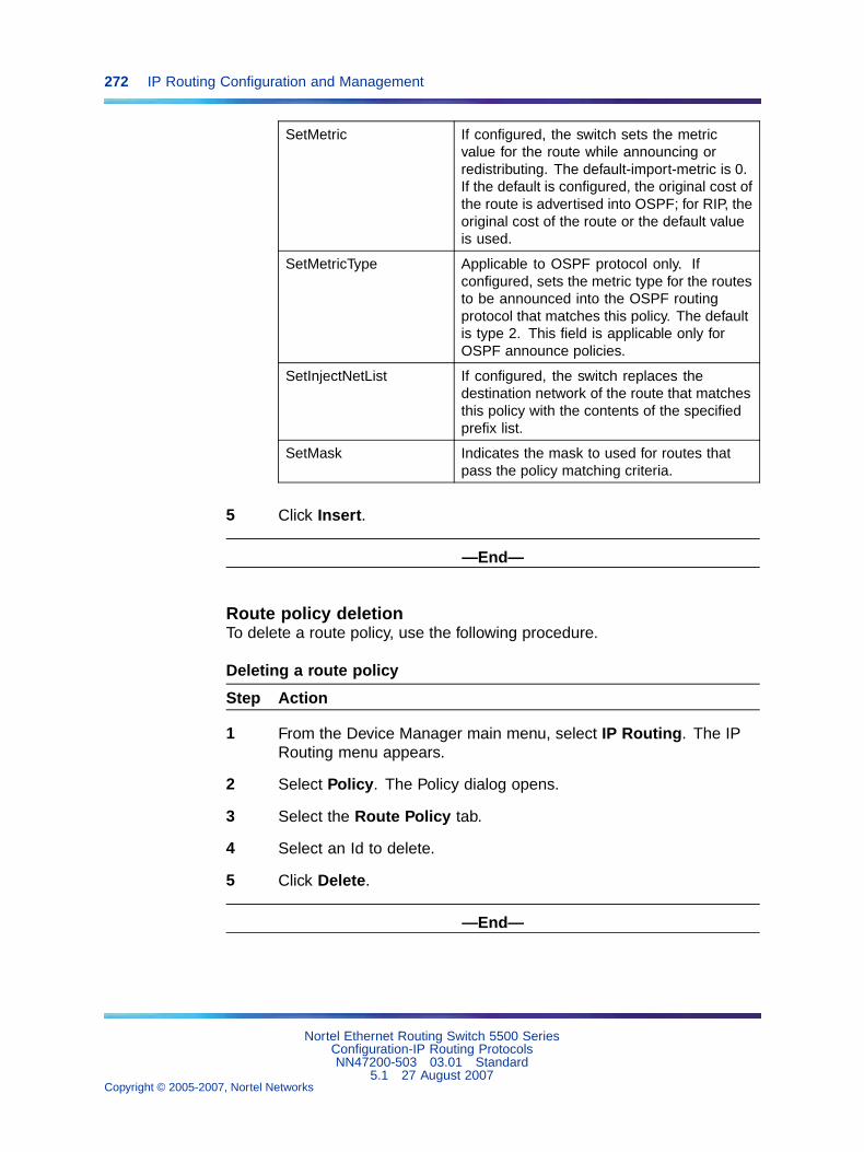
272 IP Routing Configuration and Management
SetMetric If configured, the switch sets the metricvalue for the route while announcing orredistributing. The default-import-metric is 0.If the default is configured, the original cost ofthe route is advertised into OSPF; for RIP, theoriginal cost of the route or the default valueis used.
SetMetricType Applicable to OSPF protocol only. Ifconfigured, sets the metric type for the routesto be announced into the OSPF routingprotocol that matches this policy. The defaultis type 2. This field is applicable only forOSPF announce policies.
SetInjectNetList If configured, the switch replaces thedestination network of the route that matchesthis policy with the contents of the specifiedprefix list.
SetMask Indicates the mask to used for routes thatpass the policy matching criteria.
5 Click Insert.
—End—
Route policy deletionTo delete a route policy, use the following procedure.
Deleting a route policy
Step Action
1 From the Device Manager main menu, select IP Routing. The IPRouting menu appears.
2 Select Policy. The Policy dialog opens.
3 Select the Route Policy tab.
4 Select an Id to delete.
5 Click Delete.
—End—
Nortel Ethernet Routing Switch 5500 SeriesConfiguration-IP Routing ProtocolsNN47200-503 03.01 Standard
5.1 27 August 2007Copyright © 2005-2007, Nortel Networks
.
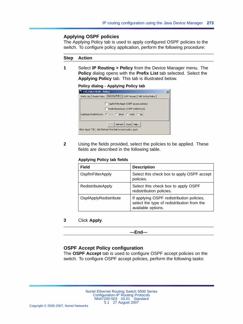
IP routing configuration using the Java Device Manager 273
Applying OSPF policiesThe Applying Policy tab is used to apply configured OSPF policies to theswitch. To configure policy application, perform the following procedure:
Step Action
1 Select IP Routing > Policy from the Device Manager menu. ThePolicy dialog opens with the Prefix List tab selected. Select theApplying Policy tab. This tab is illustrated below.
Policy dialog - Applying Policy tab
2 Using the fields provided, select the policies to be applied. Thesefields are described in the following table.
Applying Policy tab fields
Field Description
OspfInFilterApply Select this check box to apply OSPF acceptpolicies.
RedistributeApply Select this check box to apply OSPFredistribution policies.
OspfApplyRedistribute If applying OSPF redistribution policies,select the type of redistribution from theavailable options.
3 Click Apply.
—End—
OSPF Accept Policy configurationThe OSPF Accept tab is used to configure OSPF accept policies on theswitch. To configure OSPF accept policies, perform the following tasks:
Nortel Ethernet Routing Switch 5500 SeriesConfiguration-IP Routing ProtocolsNN47200-503 03.01 Standard
5.1 27 August 2007Copyright © 2005-2007, Nortel Networks
.
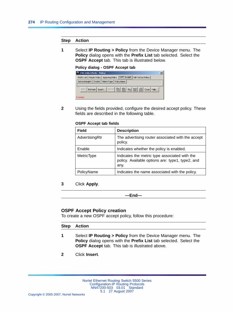
274 IP Routing Configuration and Management
Step Action
1 Select IP Routing > Policy from the Device Manager menu. ThePolicy dialog opens with the Prefix List tab selected. Select theOSPF Accept tab. This tab is illustrated below.
Policy dialog - OSPF Accept tab
2 Using the fields provided, configure the desired accept policy. Thesefields are described in the following table.
OSPF Accept tab fields
Field Description
AdvertisingRtr The advertising router associated with the acceptpolicy.
Enable Indicates whether the policy is enabled.
MetricType Indicates the metric type associated with thepolicy. Available options are: type1, type2, andany.
PolicyName Indicates the name associated with the policy.
3 Click Apply.
—End—
OSPF Accept Policy creationTo create a new OSPF accept policy, follow this procedure:
Step Action
1 Select IP Routing > Policy from the Device Manager menu. ThePolicy dialog opens with the Prefix List tab selected. Select theOSPF Accept tab. This tab is illustrated above.
2 Click Insert.
Nortel Ethernet Routing Switch 5500 SeriesConfiguration-IP Routing ProtocolsNN47200-503 03.01 Standard
5.1 27 August 2007Copyright © 2005-2007, Nortel Networks
.
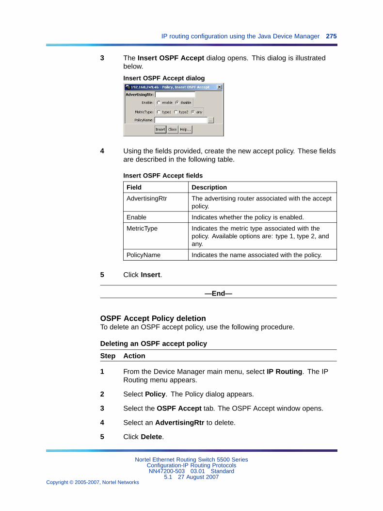
IP routing configuration using the Java Device Manager 275
3 The Insert OSPF Accept dialog opens. This dialog is illustratedbelow.
Insert OSPF Accept dialog
4 Using the fields provided, create the new accept policy. These fieldsare described in the following table.
Insert OSPF Accept fields
Field Description
AdvertisingRtr The advertising router associated with the acceptpolicy.
Enable Indicates whether the policy is enabled.
MetricType Indicates the metric type associated with thepolicy. Available options are: type 1, type 2, andany.
PolicyName Indicates the name associated with the policy.
5 Click Insert.
—End—
OSPF Accept Policy deletionTo delete an OSPF accept policy, use the following procedure.
Deleting an OSPF accept policy
Step Action
1 From the Device Manager main menu, select IP Routing. The IPRouting menu appears.
2 Select Policy. The Policy dialog appears.
3 Select the OSPF Accept tab. The OSPF Accept window opens.
4 Select an AdvertisingRtr to delete.
5 Click Delete.
Nortel Ethernet Routing Switch 5500 SeriesConfiguration-IP Routing ProtocolsNN47200-503 03.01 Standard
5.1 27 August 2007Copyright © 2005-2007, Nortel Networks
.
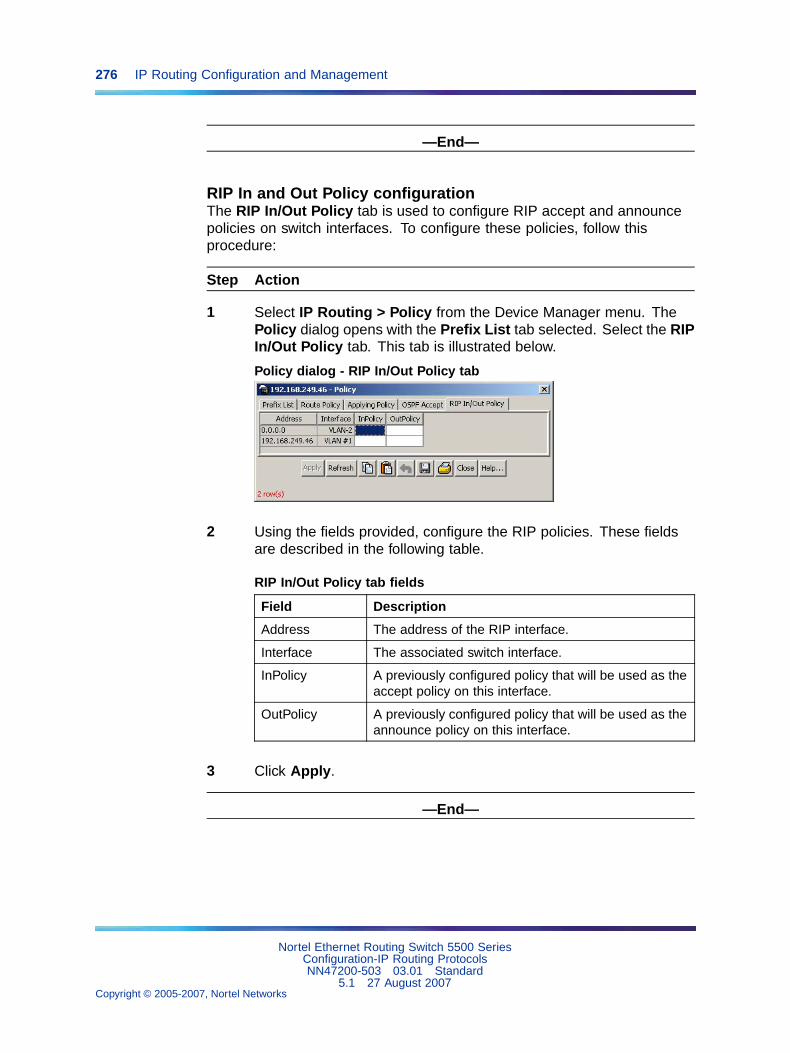
276 IP Routing Configuration and Management
—End—
RIP In and Out Policy configurationThe RIP In/Out Policy tab is used to configure RIP accept and announcepolicies on switch interfaces. To configure these policies, follow thisprocedure:
Step Action
1 Select IP Routing > Policy from the Device Manager menu. ThePolicy dialog opens with the Prefix List tab selected. Select the RIPIn/Out Policy tab. This tab is illustrated below.
Policy dialog - RIP In/Out Policy tab
2 Using the fields provided, configure the RIP policies. These fieldsare described in the following table.
RIP In/Out Policy tab fields
Field Description
Address The address of the RIP interface.
Interface The associated switch interface.
InPolicy A previously configured policy that will be used as theaccept policy on this interface.
OutPolicy A previously configured policy that will be used as theannounce policy on this interface.
3 Click Apply.
—End—
Nortel Ethernet Routing Switch 5500 SeriesConfiguration-IP Routing ProtocolsNN47200-503 03.01 Standard
5.1 27 August 2007Copyright © 2005-2007, Nortel Networks
.
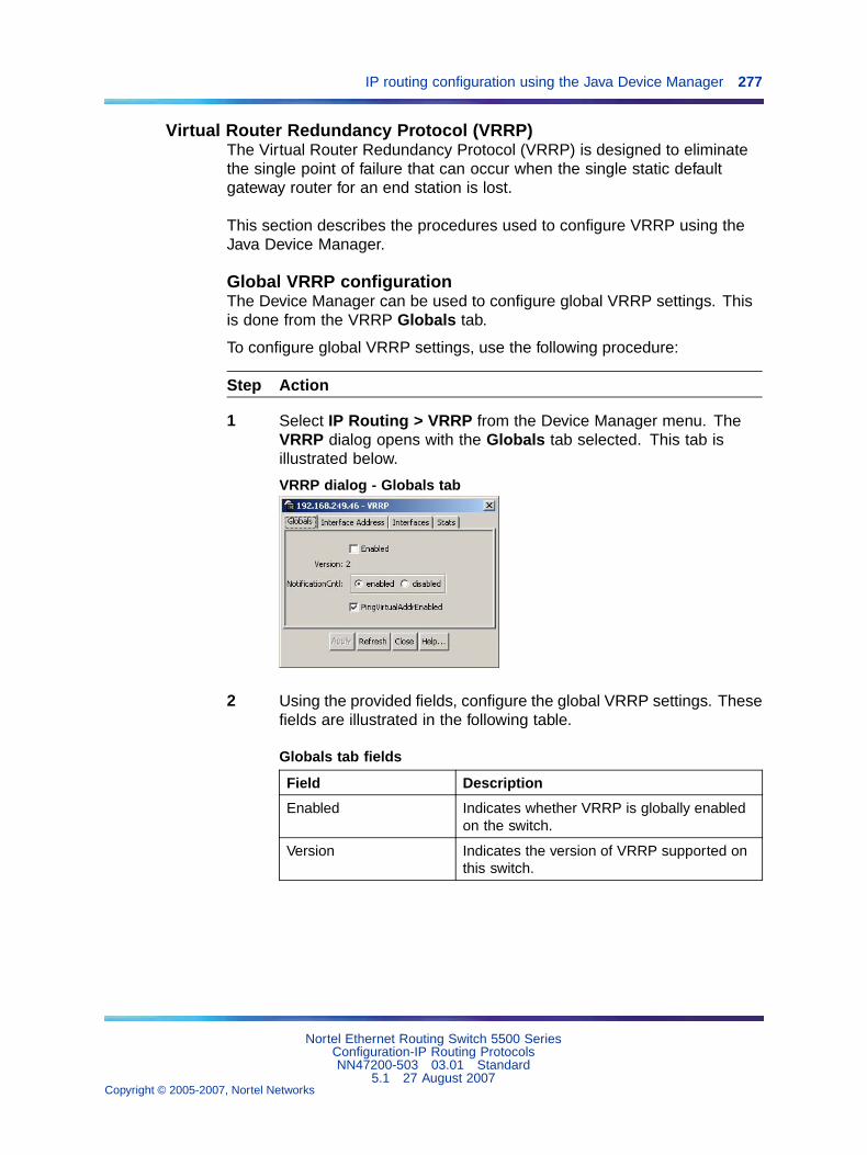
IP routing configuration using the Java Device Manager 277
Virtual Router Redundancy Protocol (VRRP)The Virtual Router Redundancy Protocol (VRRP) is designed to eliminatethe single point of failure that can occur when the single static defaultgateway router for an end station is lost.
This section describes the procedures used to configure VRRP using theJava Device Manager.
Global VRRP configurationThe Device Manager can be used to configure global VRRP settings. Thisis done from the VRRP Globals tab.
To configure global VRRP settings, use the following procedure:
Step Action
1 Select IP Routing > VRRP from the Device Manager menu. TheVRRP dialog opens with the Globals tab selected. This tab isillustrated below.
VRRP dialog - Globals tab
2 Using the provided fields, configure the global VRRP settings. Thesefields are illustrated in the following table.
Globals tab fields
Field Description
Enabled Indicates whether VRRP is globally enabledon the switch.
Version Indicates the version of VRRP supported onthis switch.
Nortel Ethernet Routing Switch 5500 SeriesConfiguration-IP Routing ProtocolsNN47200-503 03.01 Standard
5.1 27 August 2007Copyright © 2005-2007, Nortel Networks
.
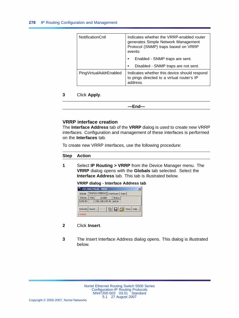
278 IP Routing Configuration and Management
NotificationCntl Indicates whether the VRRP-enabled routergenerates Simple Network ManagementProtocol (SNMP) traps based on VRRPevents:
• Enabled - SNMP traps are sent.
• Disabled - SNMP traps are not sent.
PingVirtualAddrEnabled Indicates whether this device should respondto pings directed to a virtual router’s IPaddress.
3 Click Apply.
—End—
VRRP interface creationThe Interface Address tab of the VRRP dialog is used to create new VRRPinterfaces. Configuration and management of these interfaces is performedon the Interfaces tab.
To create new VRRP interfaces, use the following procedure:
Step Action
1 Select IP Routing > VRRP from the Device Manager menu. TheVRRP dialog opens with the Globals tab selected. Select theInterface Address tab. This tab is illustrated below.
VRRP dialog - Interface Address tab
2 Click Insert.
3 The Insert Interface Address dialog opens. This dialog is illustratedbelow.
Nortel Ethernet Routing Switch 5500 SeriesConfiguration-IP Routing ProtocolsNN47200-503 03.01 Standard
5.1 27 August 2007Copyright © 2005-2007, Nortel Networks
.
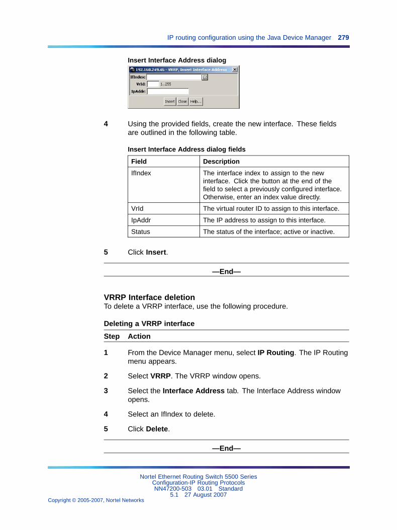
IP routing configuration using the Java Device Manager 279
Insert Interface Address dialog
4 Using the provided fields, create the new interface. These fieldsare outlined in the following table.
Insert Interface Address dialog fields
Field Description
IfIndex The interface index to assign to the newinterface. Click the button at the end of thefield to select a previously configured interface.Otherwise, enter an index value directly.
VrId The virtual router ID to assign to this interface.
IpAddr The IP address to assign to this interface.
Status The status of the interface; active or inactive.
5 Click Insert.
—End—
VRRP Interface deletionTo delete a VRRP interface, use the following procedure.
Deleting a VRRP interface
Step Action
1 From the Device Manager menu, select IP Routing. The IP Routingmenu appears.
2 Select VRRP. The VRRP window opens.
3 Select the Interface Address tab. The Interface Address windowopens.
4 Select an IfIndex to delete.
5 Click Delete.
—End—
Nortel Ethernet Routing Switch 5500 SeriesConfiguration-IP Routing ProtocolsNN47200-503 03.01 Standard
5.1 27 August 2007Copyright © 2005-2007, Nortel Networks
.
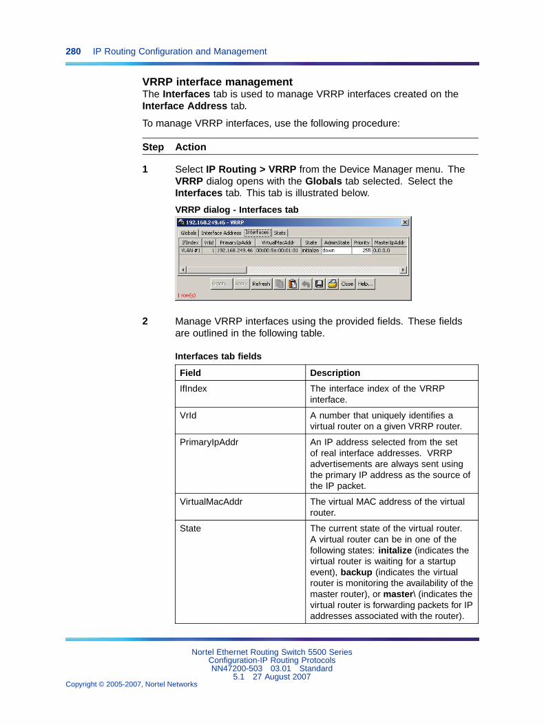
280 IP Routing Configuration and Management
VRRP interface managementThe Interfaces tab is used to manage VRRP interfaces created on theInterface Address tab.
To manage VRRP interfaces, use the following procedure:
Step Action
1 Select IP Routing > VRRP from the Device Manager menu. TheVRRP dialog opens with the Globals tab selected. Select theInterfaces tab. This tab is illustrated below.
VRRP dialog - Interfaces tab
2 Manage VRRP interfaces using the provided fields. These fieldsare outlined in the following table.
Interfaces tab fields
Field Description
IfIndex The interface index of the VRRPinterface.
VrId A number that uniquely identifies avirtual router on a given VRRP router.
PrimaryIpAddr An IP address selected from the setof real interface addresses. VRRPadvertisements are always sent usingthe primary IP address as the source ofthe IP packet.
VirtualMacAddr The virtual MAC address of the virtualrouter.
State The current state of the virtual router.A virtual router can be in one of thefollowing states: initalize (indicates thevirtual router is waiting for a startupevent), backup (indicates the virtualrouter is monitoring the availability of themaster router), or master\ (indicates thevirtual router is forwarding packets for IPaddresses associated with the router).
Nortel Ethernet Routing Switch 5500 SeriesConfiguration-IP Routing ProtocolsNN47200-503 03.01 Standard
5.1 27 August 2007Copyright © 2005-2007, Nortel Networks
.
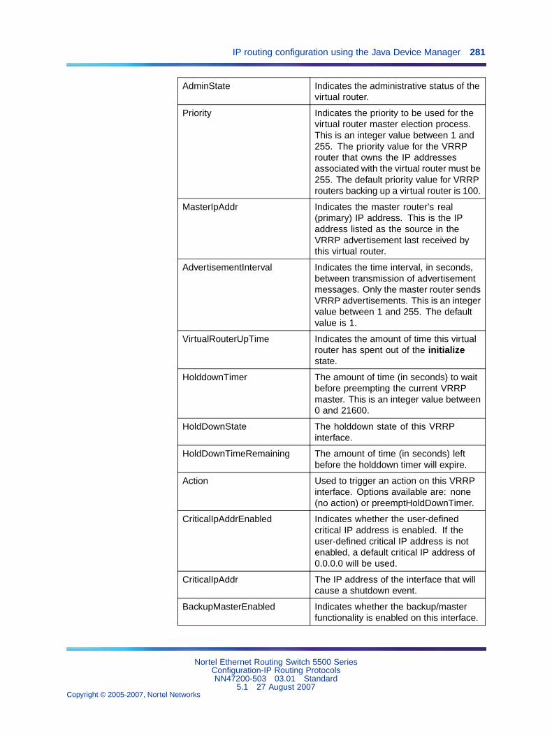
IP routing configuration using the Java Device Manager 281
AdminState Indicates the administrative status of thevirtual router.
Priority Indicates the priority to be used for thevirtual router master election process.This is an integer value between 1 and255. The priority value for the VRRProuter that owns the IP addressesassociated with the virtual router must be255. The default priority value for VRRProuters backing up a virtual router is 100.
MasterIpAddr Indicates the master router’s real(primary) IP address. This is the IPaddress listed as the source in theVRRP advertisement last received bythis virtual router.
AdvertisementInterval Indicates the time interval, in seconds,between transmission of advertisementmessages. Only the master router sendsVRRP advertisements. This is an integervalue between 1 and 255. The defaultvalue is 1.
VirtualRouterUpTime Indicates the amount of time this virtualrouter has spent out of the initializestate.
HolddownTimer The amount of time (in seconds) to waitbefore preempting the current VRRPmaster. This is an integer value between0 and 21600.
HoldDownState The holddown state of this VRRPinterface.
HoldDownTimeRemaining The amount of time (in seconds) leftbefore the holddown timer will expire.
Action Used to trigger an action on this VRRPinterface. Options available are: none(no action) or preemptHoldDownTimer.
CriticalIpAddrEnabled Indicates whether the user-definedcritical IP address is enabled. If theuser-defined critical IP address is notenabled, a default critical IP address of0.0.0.0 will be used.
CriticalIpAddr The IP address of the interface that willcause a shutdown event.
BackupMasterEnabled Indicates whether the backup/masterfunctionality is enabled on this interface.
Nortel Ethernet Routing Switch 5500 SeriesConfiguration-IP Routing ProtocolsNN47200-503 03.01 Standard
5.1 27 August 2007Copyright © 2005-2007, Nortel Networks
.
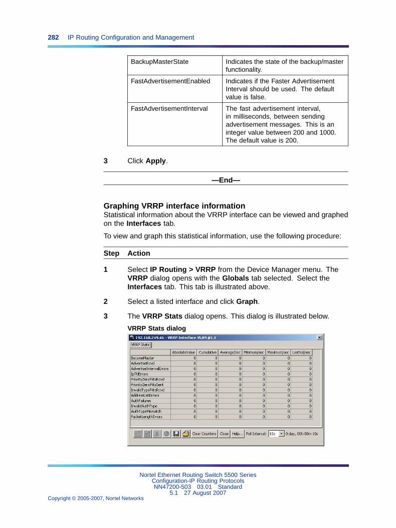
282 IP Routing Configuration and Management
BackupMasterState Indicates the state of the backup/masterfunctionality.
FastAdvertisementEnabled Indicates if the Faster AdvertisementInterval should be used. The defaultvalue is false.
FastAdvertisementInterval The fast advertisement interval,in milliseconds, between sendingadvertisement messages. This is aninteger value between 200 and 1000.The default value is 200.
3 Click Apply.
—End—
Graphing VRRP interface informationStatistical information about the VRRP interface can be viewed and graphedon the Interfaces tab.
To view and graph this statistical information, use the following procedure:
Step Action
1 Select IP Routing > VRRP from the Device Manager menu. TheVRRP dialog opens with the Globals tab selected. Select theInterfaces tab. This tab is illustrated above.
2 Select a listed interface and click Graph.
3 The VRRP Stats dialog opens. This dialog is illustrated below.
VRRP Stats dialog
Nortel Ethernet Routing Switch 5500 SeriesConfiguration-IP Routing ProtocolsNN47200-503 03.01 Standard
5.1 27 August 2007Copyright © 2005-2007, Nortel Networks
.
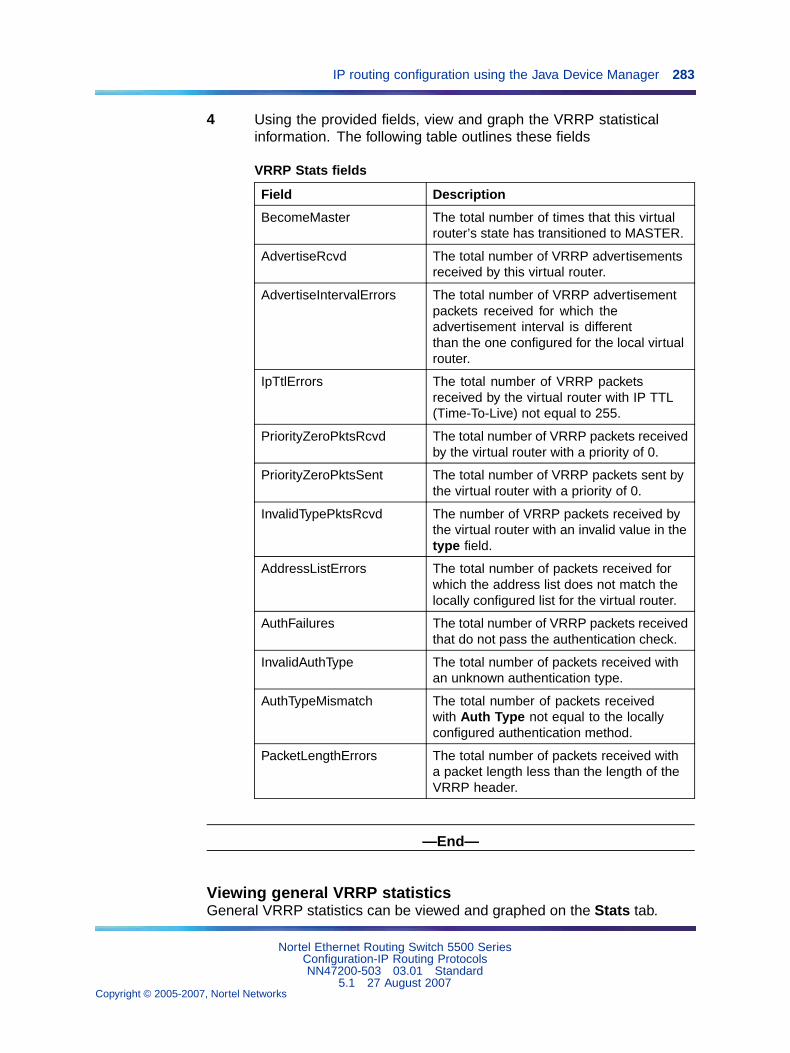
IP routing configuration using the Java Device Manager 283
4 Using the provided fields, view and graph the VRRP statisticalinformation. The following table outlines these fields
VRRP Stats fields
Field Description
BecomeMaster The total number of times that this virtualrouter’s state has transitioned to MASTER.
AdvertiseRcvd The total number of VRRP advertisementsreceived by this virtual router.
AdvertiseIntervalErrors The total number of VRRP advertisementpackets received for which theadvertisement interval is differentthan the one configured for the local virtualrouter.
IpTtlErrors The total number of VRRP packetsreceived by the virtual router with IP TTL(Time-To-Live) not equal to 255.
PriorityZeroPktsRcvd The total number of VRRP packets receivedby the virtual router with a priority of 0.
PriorityZeroPktsSent The total number of VRRP packets sent bythe virtual router with a priority of 0.
InvalidTypePktsRcvd The number of VRRP packets received bythe virtual router with an invalid value in thetype field.
AddressListErrors The total number of packets received forwhich the address list does not match thelocally configured list for the virtual router.
AuthFailures The total number of VRRP packets receivedthat do not pass the authentication check.
InvalidAuthType The total number of packets received withan unknown authentication type.
AuthTypeMismatch The total number of packets receivedwith Auth Type not equal to the locallyconfigured authentication method.
PacketLengthErrors The total number of packets received witha packet length less than the length of theVRRP header.
—End—
Viewing general VRRP statisticsGeneral VRRP statistics can be viewed and graphed on the Stats tab.
Nortel Ethernet Routing Switch 5500 SeriesConfiguration-IP Routing ProtocolsNN47200-503 03.01 Standard
5.1 27 August 2007Copyright © 2005-2007, Nortel Networks
.
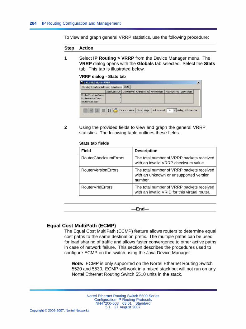
284 IP Routing Configuration and Management
To view and graph general VRRP statistics, use the following procedure:
Step Action
1 Select IP Routing > VRRP from the Device Manager menu. TheVRRP dialog opens with the Globals tab selected. Select the Statstab. This tab is illustrated below.
VRRP dialog - Stats tab
2 Using the provided fields to view and graph the general VRRPstatistics. The following table outlines these fields.
Stats tab fields
Field Description
RouterChecksumErrors The total number of VRRP packets receivedwith an invalid VRRP checksum value.
RouterVersionErrors The total number of VRRP packets receivedwith an unknown or unsupported versionnumber.
RouterVrIdErrors The total number of VRRP packets receivedwith an invalid VRID for this virtual router.
—End—
Equal Cost MultiPath (ECMP)The Equal Cost MultiPath (ECMP) feature allows routers to determine equalcost paths to the same destination prefix. The multiple paths can be usedfor load sharing of traffic and allows faster convergence to other active pathsin case of network failure. This section describes the procedures used toconfigure ECMP on the switch using the Java Device Manager.
Note: ECMP is only supported on the Nortel Ethernet Routing Switch5520 and 5530. ECMP will work in a mixed stack but will not run on anyNortel Ethernet Routing Switch 5510 units in the stack.
Nortel Ethernet Routing Switch 5500 SeriesConfiguration-IP Routing ProtocolsNN47200-503 03.01 Standard
5.1 27 August 2007Copyright © 2005-2007, Nortel Networks
.
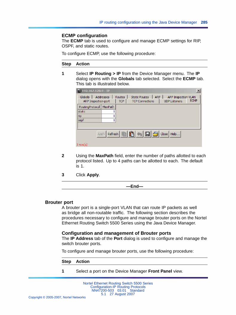
IP routing configuration using the Java Device Manager 285
ECMP configurationThe ECMP tab is used to configure and manage ECMP settings for RIP,OSPF, and static routes.
To configure ECMP, use the following procedure:
Step Action
1 Select IP Routing > IP from the Device Manager menu. The IPdialog opens with the Globals tab selected. Select the ECMP tab.This tab is illustrated below.
2 Using the MaxPath field, enter the number of paths allotted to eachprotocol listed. Up to 4 paths can be allotted to each. The defaultis 1.
3 Click Apply.
—End—
Brouter portA brouter port is a single-port VLAN that can route IP packets as wellas bridge all non-routable traffic. The following section describes theprocedures necessary to configure and manage brouter ports on the NortelEthernet Routing Switch 5500 Series using the Java Device Manager.
Configuration and management of Brouter portsThe IP Address tab of the Port dialog is used to configure and manage theswitch brouter ports.
To configure and manage brouter ports, use the following procedure:
Step Action
1 Select a port on the Device Manager Front Panel view.
Nortel Ethernet Routing Switch 5500 SeriesConfiguration-IP Routing ProtocolsNN47200-503 03.01 Standard
5.1 27 August 2007Copyright © 2005-2007, Nortel Networks
.
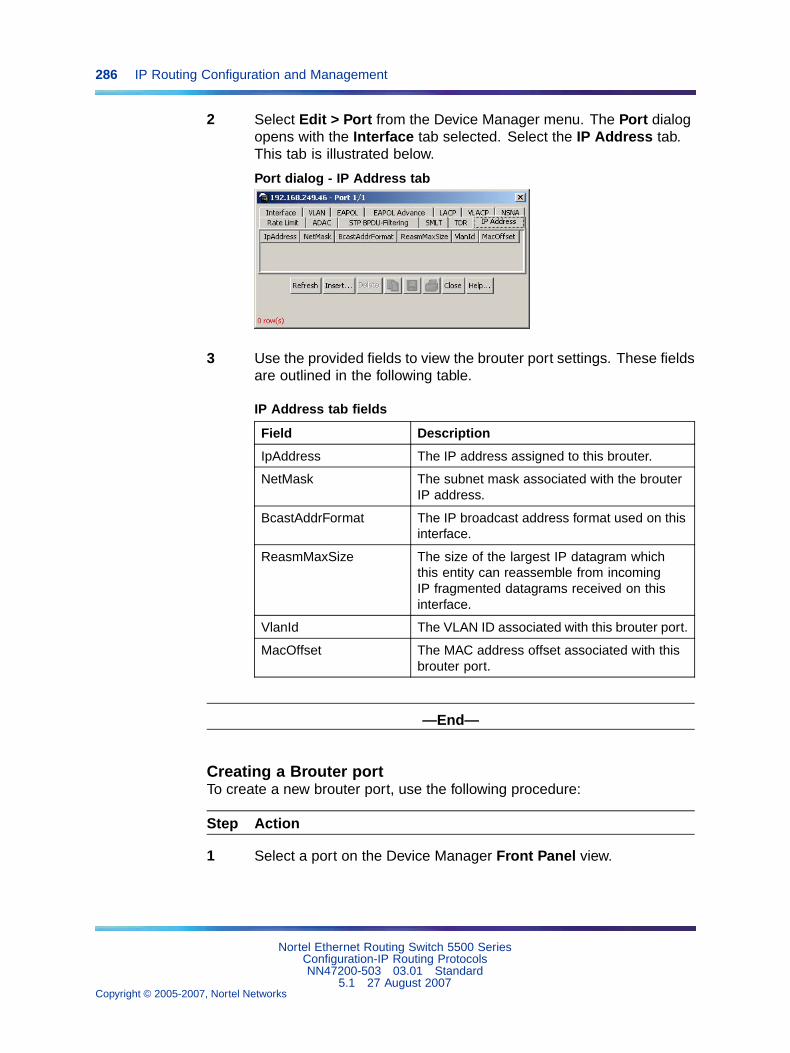
286 IP Routing Configuration and Management
2 Select Edit > Port from the Device Manager menu. The Port dialogopens with the Interface tab selected. Select the IP Address tab.This tab is illustrated below.
Port dialog - IP Address tab
3 Use the provided fields to view the brouter port settings. These fieldsare outlined in the following table.
IP Address tab fields
Field Description
IpAddress The IP address assigned to this brouter.
NetMask The subnet mask associated with the brouterIP address.
BcastAddrFormat The IP broadcast address format used on thisinterface.
ReasmMaxSize The size of the largest IP datagram whichthis entity can reassemble from incomingIP fragmented datagrams received on thisinterface.
VlanId The VLAN ID associated with this brouter port.
MacOffset The MAC address offset associated with thisbrouter port.
—End—
Creating a Brouter portTo create a new brouter port, use the following procedure:
Step Action
1 Select a port on the Device Manager Front Panel view.
Nortel Ethernet Routing Switch 5500 SeriesConfiguration-IP Routing ProtocolsNN47200-503 03.01 Standard
5.1 27 August 2007Copyright © 2005-2007, Nortel Networks
.
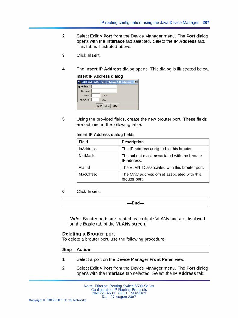
IP routing configuration using the Java Device Manager 287
2 Select Edit > Port from the Device Manager menu. The Port dialogopens with the Interface tab selected. Select the IP Address tab.This tab is illustrated above.
3 Click Insert.
4 The Insert IP Address dialog opens. This dialog is illustrated below.
Insert IP Address dialog
5 Using the provided fields, create the new brouter port. These fieldsare outlined in the following table.
Insert IP Address dialog fields
Field Description
IpAddress The IP address assigned to this brouter.
NetMask The subnet mask associated with the brouterIP address.
VlanId The VLAN ID associated with this brouter port.
MacOffset The MAC address offset associated with thisbrouter port.
6 Click Insert.
—End—
Note: Brouter ports are treated as routable VLANs and are displayedon the Basic tab of the VLANs screen.
Deleting a Brouter portTo delete a brouter port, use the following procedure:
Step Action
1 Select a port on the Device Manager Front Panel view.
2 Select Edit > Port from the Device Manager menu. The Port dialogopens with the Interface tab selected. Select the IP Address tab.
Nortel Ethernet Routing Switch 5500 SeriesConfiguration-IP Routing ProtocolsNN47200-503 03.01 Standard
5.1 27 August 2007Copyright © 2005-2007, Nortel Networks
.
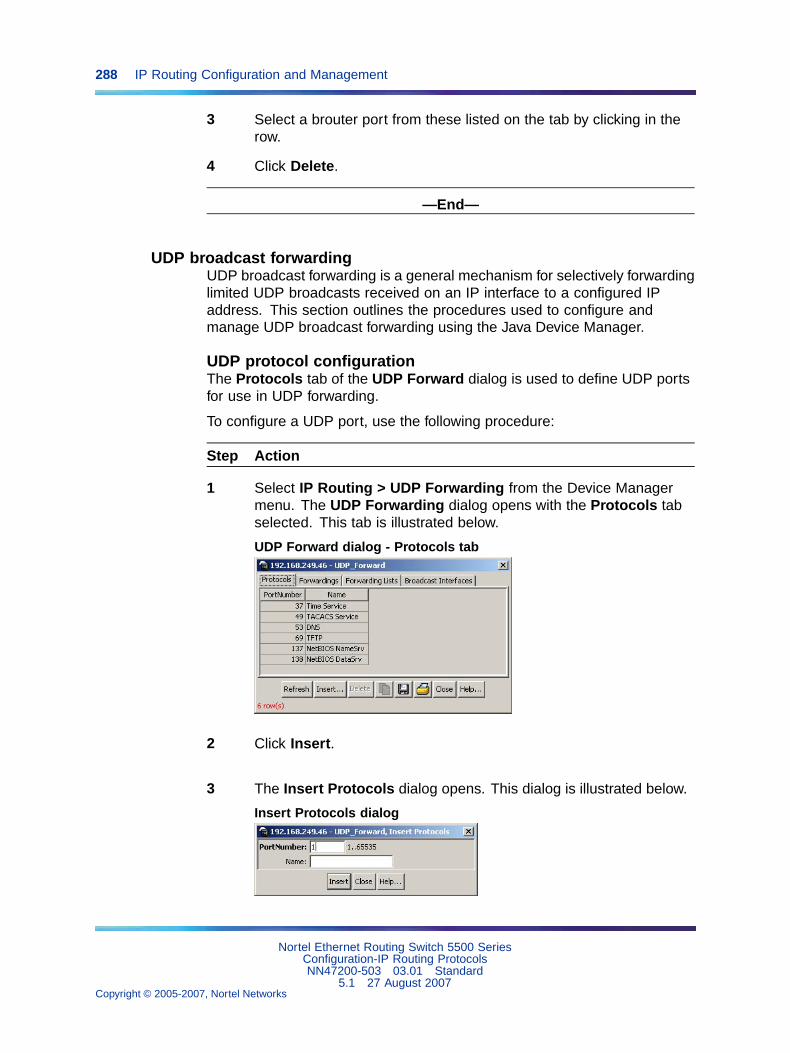
288 IP Routing Configuration and Management
3 Select a brouter port from these listed on the tab by clicking in therow.
4 Click Delete.
—End—
UDP broadcast forwardingUDP broadcast forwarding is a general mechanism for selectively forwardinglimited UDP broadcasts received on an IP interface to a configured IPaddress. This section outlines the procedures used to configure andmanage UDP broadcast forwarding using the Java Device Manager.
UDP protocol configurationThe Protocols tab of the UDP Forward dialog is used to define UDP portsfor use in UDP forwarding.
To configure a UDP port, use the following procedure:
Step Action
1 Select IP Routing > UDP Forwarding from the Device Managermenu. The UDP Forwarding dialog opens with the Protocols tabselected. This tab is illustrated below.
UDP Forward dialog - Protocols tab
2 Click Insert.
3 The Insert Protocols dialog opens. This dialog is illustrated below.
Insert Protocols dialog
Nortel Ethernet Routing Switch 5500 SeriesConfiguration-IP Routing ProtocolsNN47200-503 03.01 Standard
5.1 27 August 2007Copyright © 2005-2007, Nortel Networks
.
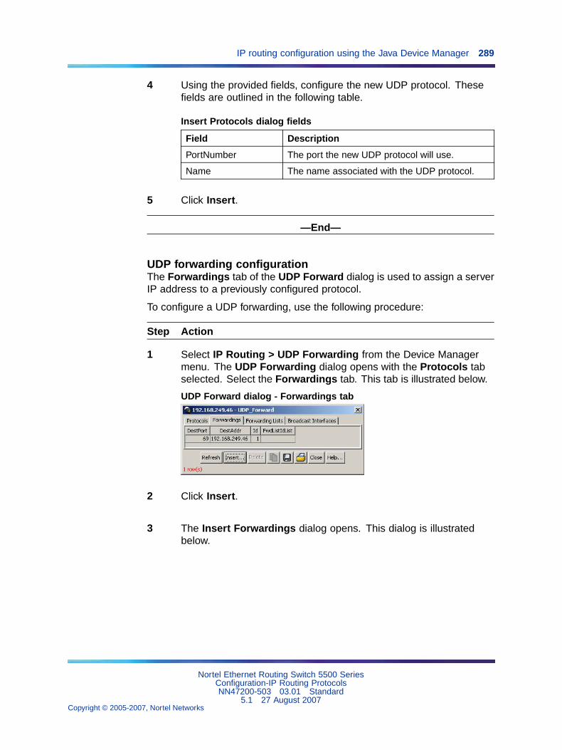
IP routing configuration using the Java Device Manager 289
4 Using the provided fields, configure the new UDP protocol. Thesefields are outlined in the following table.
Insert Protocols dialog fields
Field Description
PortNumber The port the new UDP protocol will use.
Name The name associated with the UDP protocol.
5 Click Insert.
—End—
UDP forwarding configurationThe Forwardings tab of the UDP Forward dialog is used to assign a serverIP address to a previously configured protocol.
To configure a UDP forwarding, use the following procedure:
Step Action
1 Select IP Routing > UDP Forwarding from the Device Managermenu. The UDP Forwarding dialog opens with the Protocols tabselected. Select the Forwardings tab. This tab is illustrated below.
UDP Forward dialog - Forwardings tab
2 Click Insert.
3 The Insert Forwardings dialog opens. This dialog is illustratedbelow.
Nortel Ethernet Routing Switch 5500 SeriesConfiguration-IP Routing ProtocolsNN47200-503 03.01 Standard
5.1 27 August 2007Copyright © 2005-2007, Nortel Networks
.
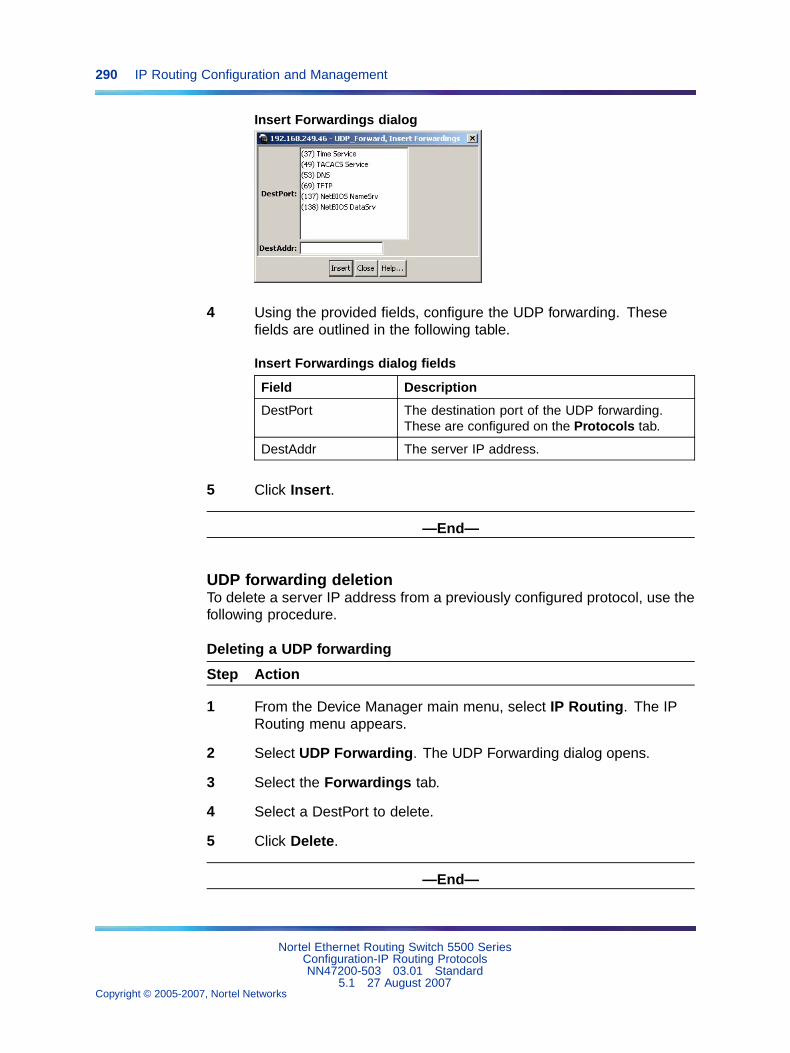
290 IP Routing Configuration and Management
Insert Forwardings dialog
4 Using the provided fields, configure the UDP forwarding. Thesefields are outlined in the following table.
Insert Forwardings dialog fields
Field Description
DestPort The destination port of the UDP forwarding.These are configured on the Protocols tab.
DestAddr The server IP address.
5 Click Insert.
—End—
UDP forwarding deletionTo delete a server IP address from a previously configured protocol, use thefollowing procedure.
Deleting a UDP forwarding
Step Action
1 From the Device Manager main menu, select IP Routing. The IPRouting menu appears.
2 Select UDP Forwarding. The UDP Forwarding dialog opens.
3 Select the Forwardings tab.
4 Select a DestPort to delete.
5 Click Delete.
—End—
Nortel Ethernet Routing Switch 5500 SeriesConfiguration-IP Routing ProtocolsNN47200-503 03.01 Standard
5.1 27 August 2007Copyright © 2005-2007, Nortel Networks
.
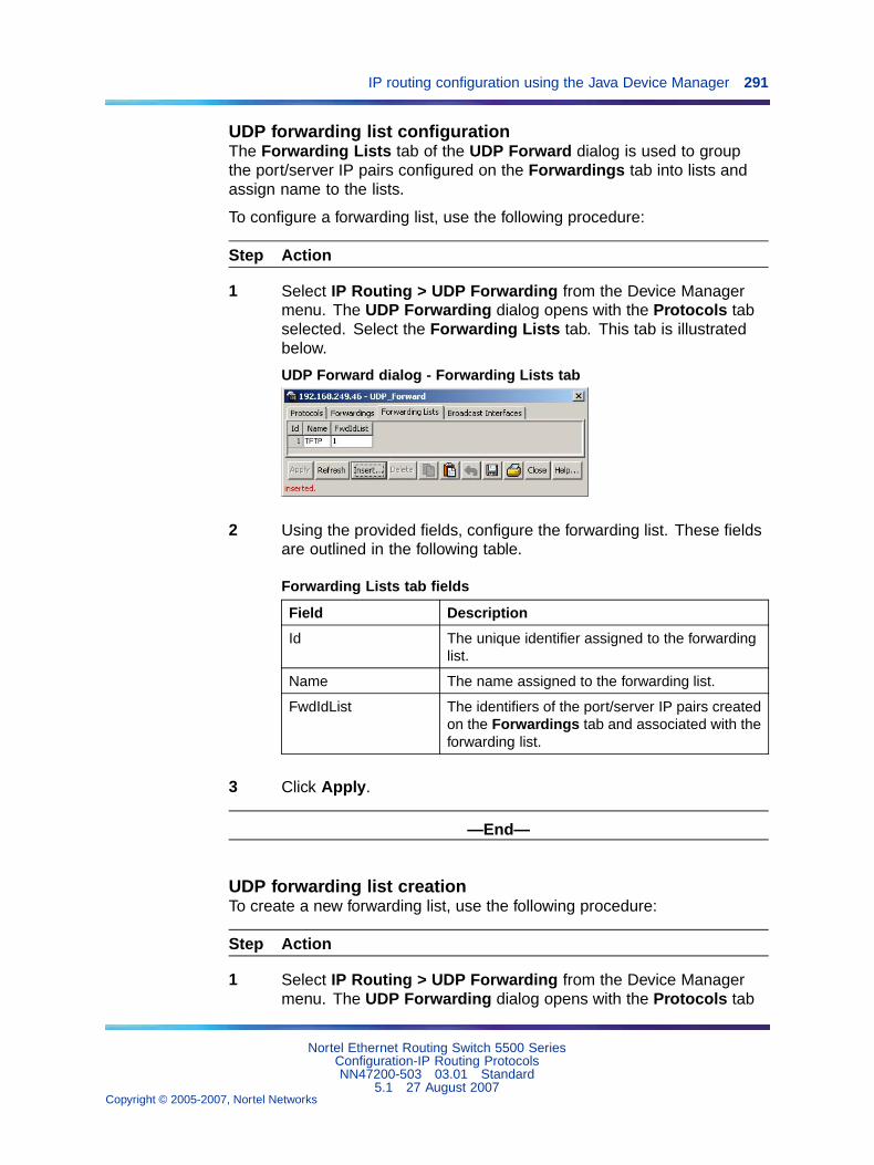
IP routing configuration using the Java Device Manager 291
UDP forwarding list configurationThe Forwarding Lists tab of the UDP Forward dialog is used to groupthe port/server IP pairs configured on the Forwardings tab into lists andassign name to the lists.
To configure a forwarding list, use the following procedure:
Step Action
1 Select IP Routing > UDP Forwarding from the Device Managermenu. The UDP Forwarding dialog opens with the Protocols tabselected. Select the Forwarding Lists tab. This tab is illustratedbelow.
UDP Forward dialog - Forwarding Lists tab
2 Using the provided fields, configure the forwarding list. These fieldsare outlined in the following table.
Forwarding Lists tab fields
Field Description
Id The unique identifier assigned to the forwardinglist.
Name The name assigned to the forwarding list.
FwdIdList The identifiers of the port/server IP pairs createdon the Forwardings tab and associated with theforwarding list.
3 Click Apply.
—End—
UDP forwarding list creationTo create a new forwarding list, use the following procedure:
Step Action
1 Select IP Routing > UDP Forwarding from the Device Managermenu. The UDP Forwarding dialog opens with the Protocols tab
Nortel Ethernet Routing Switch 5500 SeriesConfiguration-IP Routing ProtocolsNN47200-503 03.01 Standard
5.1 27 August 2007Copyright © 2005-2007, Nortel Networks
.
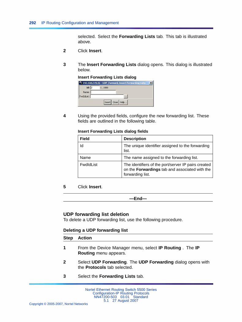
292 IP Routing Configuration and Management
selected. Select the Forwarding Lists tab. This tab is illustratedabove.
2 Click Insert.
3 The Insert Forwarding Lists dialog opens. This dialog is illustratedbelow.
Insert Forwarding Lists dialog
4 Using the provided fields, configure the new forwarding list. Thesefields are outlined in the following table.
Insert Forwarding Lists dialog fields
Field Description
Id The unique identifier assigned to the forwardinglist.
Name The name assigned to the forwarding list.
FwdIdList The identifiers of the port/server IP pairs createdon the Forwardings tab and associated with theforwarding list.
5 Click Insert.
—End—
UDP forwarding list deletionTo delete a UDP forwarding list, use the following procedure.
Deleting a UDP forwarding list
Step Action
1 From the Device Manager menu, select IP Routing . The IPRouting menu appears.
2 Select UDP Forwarding. The UDP Forwarding dialog opens withthe Protocols tab selected.
3 Select the Forwarding Lists tab.
Nortel Ethernet Routing Switch 5500 SeriesConfiguration-IP Routing ProtocolsNN47200-503 03.01 Standard
5.1 27 August 2007Copyright © 2005-2007, Nortel Networks
.
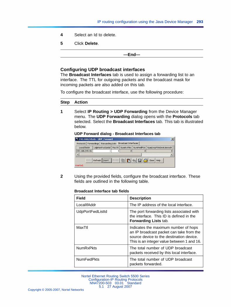
IP routing configuration using the Java Device Manager 293
4 Select an Id to delete.
5 Click Delete.
—End—
Configuring UDP broadcast interfacesThe Broadcast Interfaces tab is used to assign a forwarding list to aninterface. The TTL for outgoing packets and the broadcast mask forincoming packets are also added on this tab.
To configure the broadcast interface, use the following procedure:
Step Action
1 Select IP Routing > UDP Forwarding from the Device Managermenu. The UDP Forwarding dialog opens with the Protocols tabselected. Select the Broadcast Interfaces tab. This tab is illustratedbelow.
UDP Forward dialog - Broadcast Interfaces tab
2 Using the provided fields, configure the broadcast interface. Thesefields are outlined in the following table.
Broadcast Interface tab fields
Field Description
LocalIfAddr The IP address of the local interface.
UdpPortFwdListId The port forwarding lists associated withthe interface. This ID is defined in theForwarding Lists tab.
MaxTtl Indicates the maximum number of hopsan IP broadcast packet can take from thesource device to the destination device.This is an integer value between 1 and 16.
NumRxPkts The total number of UDP broadcastpackets received by this local interface.
NumFwdPkts The total number of UDP broadcastpackets forwarded.
Nortel Ethernet Routing Switch 5500 SeriesConfiguration-IP Routing ProtocolsNN47200-503 03.01 Standard
5.1 27 August 2007Copyright © 2005-2007, Nortel Networks
.
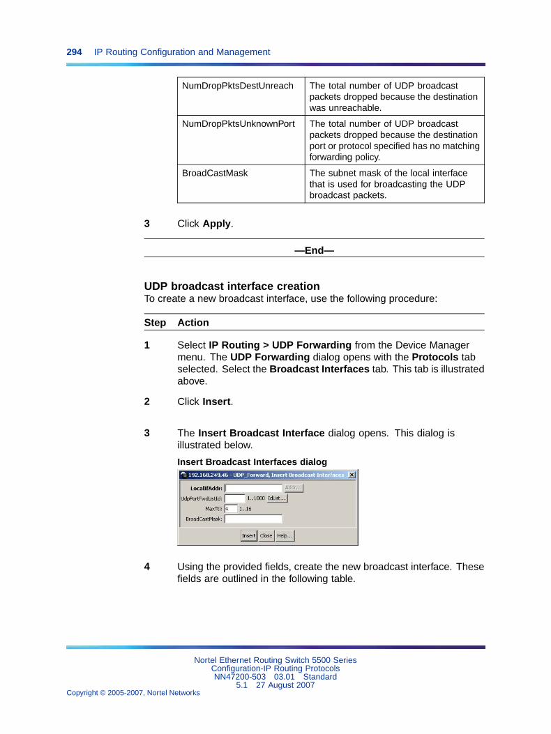
294 IP Routing Configuration and Management
NumDropPktsDestUnreach The total number of UDP broadcastpackets dropped because the destinationwas unreachable.
NumDropPktsUnknownPort The total number of UDP broadcastpackets dropped because the destinationport or protocol specified has no matchingforwarding policy.
BroadCastMask The subnet mask of the local interfacethat is used for broadcasting the UDPbroadcast packets.
3 Click Apply.
—End—
UDP broadcast interface creationTo create a new broadcast interface, use the following procedure:
Step Action
1 Select IP Routing > UDP Forwarding from the Device Managermenu. The UDP Forwarding dialog opens with the Protocols tabselected. Select the Broadcast Interfaces tab. This tab is illustratedabove.
2 Click Insert.
3 The Insert Broadcast Interface dialog opens. This dialog isillustrated below.
Insert Broadcast Interfaces dialog
4 Using the provided fields, create the new broadcast interface. Thesefields are outlined in the following table.
Nortel Ethernet Routing Switch 5500 SeriesConfiguration-IP Routing ProtocolsNN47200-503 03.01 Standard
5.1 27 August 2007Copyright © 2005-2007, Nortel Networks
.
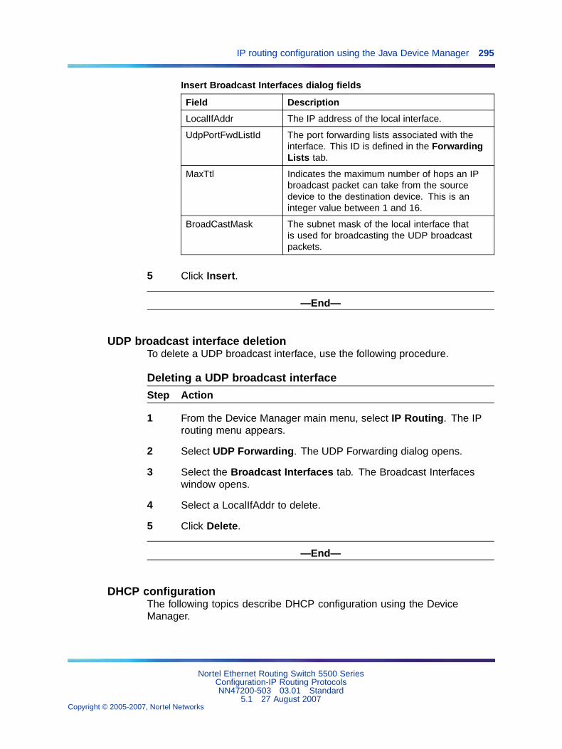
IP routing configuration using the Java Device Manager 295
Insert Broadcast Interfaces dialog fields
Field Description
LocalIfAddr The IP address of the local interface.
UdpPortFwdListId The port forwarding lists associated with theinterface. This ID is defined in the ForwardingLists tab.
MaxTtl Indicates the maximum number of hops an IPbroadcast packet can take from the sourcedevice to the destination device. This is aninteger value between 1 and 16.
BroadCastMask The subnet mask of the local interface thatis used for broadcasting the UDP broadcastpackets.
5 Click Insert.
—End—
UDP broadcast interface deletionTo delete a UDP broadcast interface, use the following procedure.
Deleting a UDP broadcast interface
Step Action
1 From the Device Manager main menu, select IP Routing. The IProuting menu appears.
2 Select UDP Forwarding. The UDP Forwarding dialog opens.
3 Select the Broadcast Interfaces tab. The Broadcast Interfaceswindow opens.
4 Select a LocalIfAddr to delete.
5 Click Delete.
—End—
DHCP configurationThe following topics describe DHCP configuration using the DeviceManager.
Nortel Ethernet Routing Switch 5500 SeriesConfiguration-IP Routing ProtocolsNN47200-503 03.01 Standard
5.1 27 August 2007Copyright © 2005-2007, Nortel Networks
.
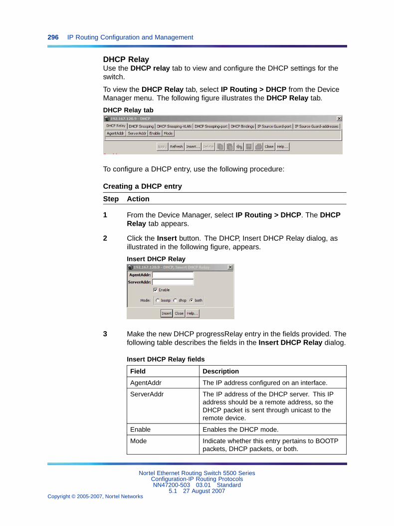
296 IP Routing Configuration and Management
DHCP RelayUse the DHCP relay tab to view and configure the DHCP settings for theswitch.
To view the DHCP Relay tab, select IP Routing > DHCP from the DeviceManager menu. The following figure illustrates the DHCP Relay tab.
DHCP Relay tab
To configure a DHCP entry, use the following procedure:
Creating a DHCP entry
Step Action
1 From the Device Manager, select IP Routing > DHCP. The DHCPRelay tab appears.
2 Click the Insert button. The DHCP, Insert DHCP Relay dialog, asillustrated in the following figure, appears.
Insert DHCP Relay
3 Make the new DHCP progressRelay entry in the fields provided. Thefollowing table describes the fields in the Insert DHCP Relay dialog.
Insert DHCP Relay fields
Field Description
AgentAddr The IP address configured on an interface.
ServerAddr The IP address of the DHCP server. This IPaddress should be a remote address, so theDHCP packet is sent through unicast to theremote device.
Enable Enables the DHCP mode.
Mode Indicate whether this entry pertains to BOOTPpackets, DHCP packets, or both.
Nortel Ethernet Routing Switch 5500 SeriesConfiguration-IP Routing ProtocolsNN47200-503 03.01 Standard
5.1 27 August 2007Copyright © 2005-2007, Nortel Networks
.
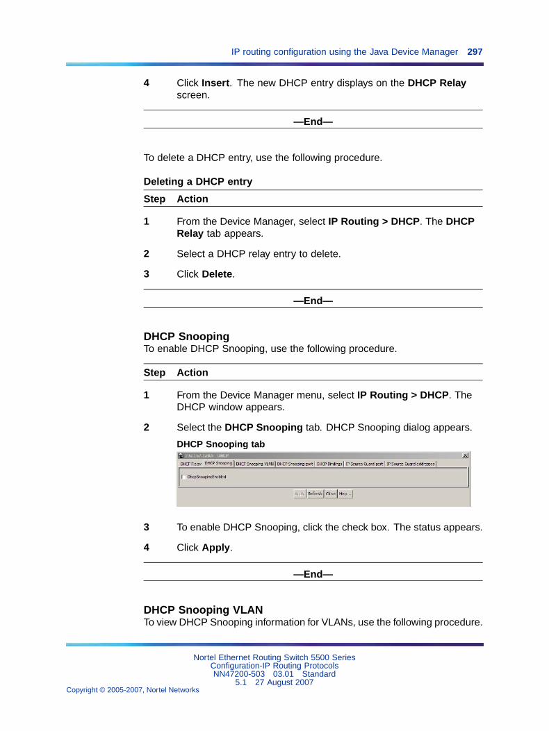
IP routing configuration using the Java Device Manager 297
4 Click Insert. The new DHCP entry displays on the DHCP Relayscreen.
—End—
To delete a DHCP entry, use the following procedure.
Deleting a DHCP entry
Step Action
1 From the Device Manager, select IP Routing > DHCP. The DHCPRelay tab appears.
2 Select a DHCP relay entry to delete.
3 Click Delete.
—End—
DHCP SnoopingTo enable DHCP Snooping, use the following procedure.
Step Action
1 From the Device Manager menu, select IP Routing > DHCP. TheDHCP window appears.
2 Select the DHCP Snooping tab. DHCP Snooping dialog appears.
DHCP Snooping tab
3 To enable DHCP Snooping, click the check box. The status appears.
4 Click Apply.
—End—
DHCP Snooping VLANTo view DHCP Snooping information for VLANs, use the following procedure.
Nortel Ethernet Routing Switch 5500 SeriesConfiguration-IP Routing ProtocolsNN47200-503 03.01 Standard
5.1 27 August 2007Copyright © 2005-2007, Nortel Networks
.
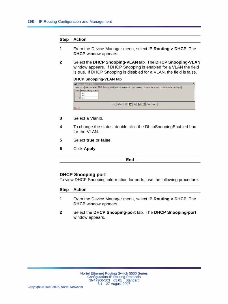
298 IP Routing Configuration and Management
Step Action
1 From the Device Manager menu, select IP Routing > DHCP. TheDHCP window appears.
2 Select the DHCP Snooping-VLAN tab. The DHCP Snooping-VLANwindow appears. If DHCP Snooping is enabled for a VLAN the fieldis true. If DHCP Snooping is disabled for a VLAN, the field is false.
DHCP Snooping-VLAN tab
3 Select a VlanId.
4 To change the status, double click the DhcpSnoopingEnabled boxfor the VLAN.
5 Select true or false.
6 Click Apply.
—End—
DHCP Snooping portTo view DHCP Snooping information for ports, use the following procedure.
Step Action
1 From the Device Manager menu, select IP Routing > DHCP. TheDHCP window appears.
2 Select the DHCP Snooping-port tab. The DHCP Snooping-portwindow appears.
Nortel Ethernet Routing Switch 5500 SeriesConfiguration-IP Routing ProtocolsNN47200-503 03.01 Standard
5.1 27 August 2007Copyright © 2005-2007, Nortel Networks
.
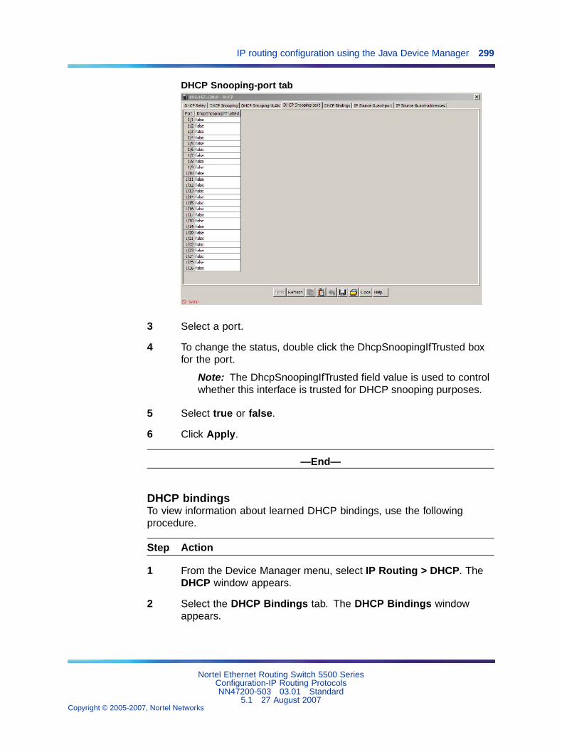
IP routing configuration using the Java Device Manager 299
DHCP Snooping-port tab
3 Select a port.
4 To change the status, double click the DhcpSnoopingIfTrusted boxfor the port.
Note: The DhcpSnoopingIfTrusted field value is used to controlwhether this interface is trusted for DHCP snooping purposes.
5 Select true or false.
6 Click Apply.
—End—
DHCP bindingsTo view information about learned DHCP bindings, use the followingprocedure.
Step Action
1 From the Device Manager menu, select IP Routing > DHCP. TheDHCP window appears.
2 Select the DHCP Bindings tab. The DHCP Bindings windowappears.
Nortel Ethernet Routing Switch 5500 SeriesConfiguration-IP Routing ProtocolsNN47200-503 03.01 Standard
5.1 27 August 2007Copyright © 2005-2007, Nortel Networks
.
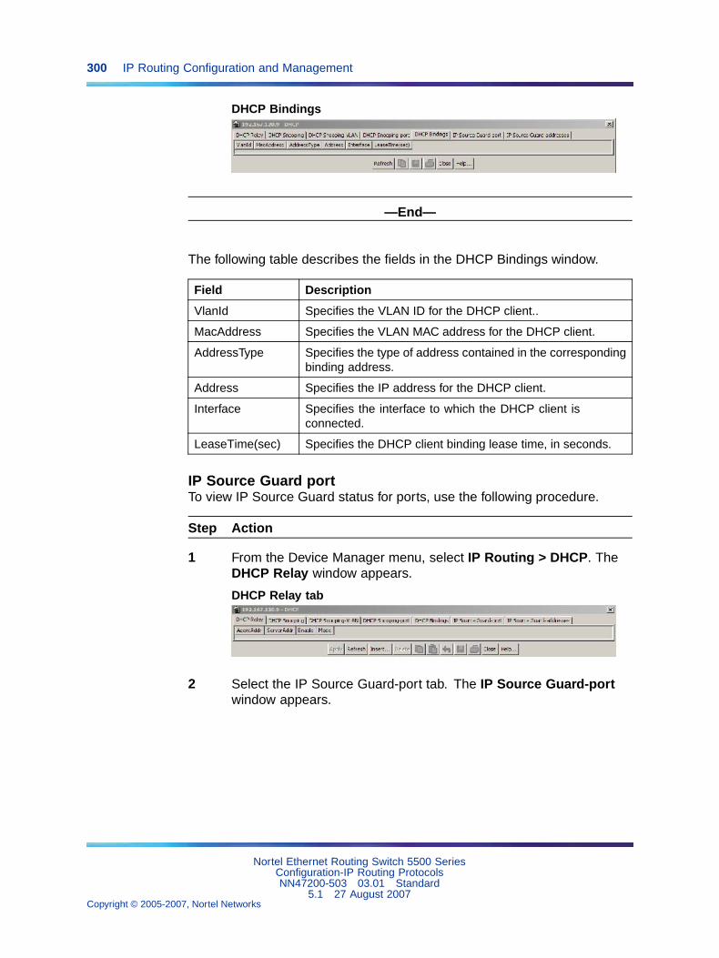
300 IP Routing Configuration and Management
DHCP Bindings
—End—
The following table describes the fields in the DHCP Bindings window.
Field Description
VlanId Specifies the VLAN ID for the DHCP client..
MacAddress Specifies the VLAN MAC address for the DHCP client.
AddressType Specifies the type of address contained in the correspondingbinding address.
Address Specifies the IP address for the DHCP client.
Interface Specifies the interface to which the DHCP client isconnected.
LeaseTime(sec) Specifies the DHCP client binding lease time, in seconds.
IP Source Guard portTo view IP Source Guard status for ports, use the following procedure.
Step Action
1 From the Device Manager menu, select IP Routing > DHCP. TheDHCP Relay window appears.
DHCP Relay tab
2 Select the IP Source Guard-port tab. The IP Source Guard-portwindow appears.
Nortel Ethernet Routing Switch 5500 SeriesConfiguration-IP Routing ProtocolsNN47200-503 03.01 Standard
5.1 27 August 2007Copyright © 2005-2007, Nortel Networks
.
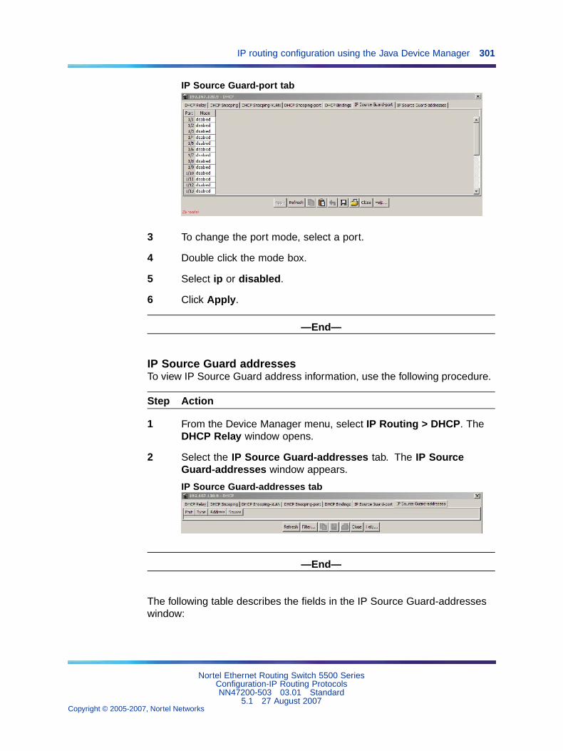
IP routing configuration using the Java Device Manager 301
IP Source Guard-port tab
3 To change the port mode, select a port.
4 Double click the mode box.
5 Select ip or disabled.
6 Click Apply.
—End—
IP Source Guard addressesTo view IP Source Guard address information, use the following procedure.
Step Action
1 From the Device Manager menu, select IP Routing > DHCP. TheDHCP Relay window opens.
2 Select the IP Source Guard-addresses tab. The IP SourceGuard-addresses window appears.
IP Source Guard-addresses tab
—End—
The following table describes the fields in the IP Source Guard-addresseswindow:
Nortel Ethernet Routing Switch 5500 SeriesConfiguration-IP Routing ProtocolsNN47200-503 03.01 Standard
5.1 27 August 2007Copyright © 2005-2007, Nortel Networks
.
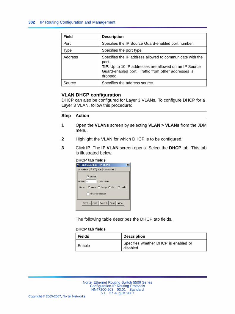
302 IP Routing Configuration and Management
Field Description
Port Specifies the IP Source Guard-enabled port number.
Type Specifies the port type.
Address Specifies the IP address allowed to communicate with theport.TIP: Up to 10 IP addresses are allowed on an IP SourceGuard-enabled port. Traffic from other addresses isdropped.
Source Specifies the address source.
VLAN DHCP configurationDHCP can also be configured for Layer 3 VLANs. To configure DHCP for aLayer 3 VLAN, follow this procedure:
Step Action
1 Open the VLANs screen by selecting VLAN > VLANs from the JDMmenu.
2 Highlight the VLAN for which DHCP is to be configured.
3 Click IP. The IP VLAN screen opens. Select the DHCP tab. This tabis illustrated below.
DHCP tab fields
The following table describes the DHCP tab fields.
DHCP tab fields
Fields Description
EnableSpecifies whether DHCP is enabled ordisabled.
Nortel Ethernet Routing Switch 5500 SeriesConfiguration-IP Routing ProtocolsNN47200-503 03.01 Standard
5.1 27 August 2007Copyright © 2005-2007, Nortel Networks
.
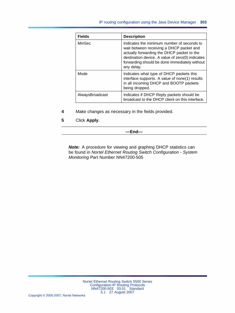
IP routing configuration using the Java Device Manager 303
Fields Description
MinSec Indicates the minimum number of seconds towait between receiving a DHCP packet andactually forwarding the DHCP packet to thedestination device. A value of zero(0) indicatesforwarding should be done immediately withoutany delay.
Mode Indicates what type of DHCP packets thisinterface supports. A value of none(1) resultsin all incoming DHCP and BOOTP packetsbeing dropped.
AlwaysBroadcast Indicates if DHCP Reply packets should bebroadcast to the DHCP client on this interface.
4 Make changes as necessary in the fields provided.
5 Click Apply.
—End—
Note: A procedure for viewing and graphing DHCP statistics canbe found in Nortel Ethernet Routing Switch Configuration - SystemMonitoring Part Number NN47200-505
Nortel Ethernet Routing Switch 5500 SeriesConfiguration-IP Routing ProtocolsNN47200-503 03.01 Standard
5.1 27 August 2007Copyright © 2005-2007, Nortel Networks
.

304 IP Routing Configuration and Management
Nortel Ethernet Routing Switch 5500 SeriesConfiguration-IP Routing ProtocolsNN47200-503 03.01 Standard
5.1 27 August 2007Copyright © 2005-2007, Nortel Networks
.
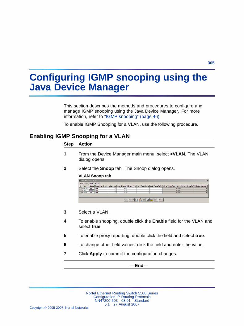
305
Configuring IGMP snooping using theJava Device Manager
This section describes the methods and procedures to configure andmanage IGMP snooping using the Java Device Manager. For moreinformation, refer to "IGMP snooping" (page 46)
To enable IGMP Snooping for a VLAN, use the following procedure.
Enabling IGMP Snooping for a VLANStep Action
1 From the Device Manager main menu, select >VLAN. The VLANdialog opens.
2 Select the Snoop tab. The Snoop dialog opens.
VLAN Snoop tab
3 Select a VLAN.
4 To enable snooping, double click the Enable field for the VLAN andselect true.
5 To enable proxy reporting, double click the field and select true.
6 To change other field values, click the field and enter the value.
7 Click Apply to commit the configuration changes.
—End—
Nortel Ethernet Routing Switch 5500 SeriesConfiguration-IP Routing ProtocolsNN47200-503 03.01 Standard
5.1 27 August 2007Copyright © 2005-2007, Nortel Networks
.
306 Configuring IGMP snooping using the Java Device Manager
TIP: You can change the presentation order of the VLANs in the Snooptable. Click the column name of any column. An up or down arrow, indicatingascending or descending order, appears next to the column name.
VLAN Snoop tab fields
Field Description
Id The number assigned to the VLAN during creation.
Name The VLAN name.
Enable Specifies snooping status:
• if false, snooping is disabled
• if true, snooping is enabled
ReportProxyEnable Specifies the IGMP report proxy status.
• if false, no proxy report generates
• if true, a proxy report (IGMP host membership report)generates
The default ReportProxyEnable setting is false (disabled).
Robustness Specifies the robust value. Use a Robustness value totune the system for the expected packet loss on a subnet.
Note: If a subnet experiences unacceptably high packetlosses, increase the Robustness value.
The default Robustness value is 2.
QueryInterval Specifies the query time, in seconds, between IGMP hostand query packets transmitted on an interface.QueryInterval, the time between general queries sentby the multicast router, controls the number of IGMPmessages allowed on the subnet
The default setting is 125 seconds.
MRouterPorts Displays the set of ports in the VLAN providingconnectivity to an IP multicast router.
Ver1MRouterPorts Displays the set of ports in the VLAN providingconnectivity to an IP Multicast router using IGMP version1.
Ver2MRouterPorts Displays the set of ports in the VLAN providingconnectivity to an IP Multicast router using IGMP version2.
ActiveMRouterPorts Displays the set of active ports in the VLAN providingconnectivity to an IP Multicast router.
ActiveQuerier Displays the IP address of a multicast querier router.
Nortel Ethernet Routing Switch 5500 SeriesConfiguration-IP Routing ProtocolsNN47200-503 03.01 Standard
5.1 27 August 2007Copyright © 2005-2007, Nortel Networks
.

Enabling IGMP Snooping for a VLAN 307
Field Description
QuerierPort Displays the port on which the multicast querier routerwas heard.
MRouterExpiration Displays the multicast querier router aging timeout value.
Nortel Ethernet Routing Switch 5500 SeriesConfiguration-IP Routing ProtocolsNN47200-503 03.01 Standard
5.1 27 August 2007Copyright © 2005-2007, Nortel Networks
.

308 Configuring IGMP snooping using the Java Device Manager
Nortel Ethernet Routing Switch 5500 SeriesConfiguration-IP Routing ProtocolsNN47200-503 03.01 Standard
5.1 27 August 2007Copyright © 2005-2007, Nortel Networks
.
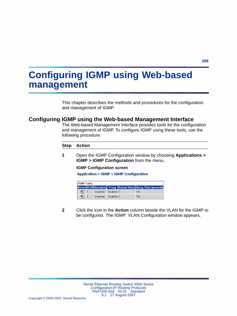
309
Configuring IGMP using Web-basedmanagement
This chapter describes the methods and procedures for the configurationand management of IGMP.
Configuring IGMP using the Web-based Management InterfaceThe Web-based Management Interface provides tools for the configurationand management of IGMP. To configure IGMP using these tools, use thefollowing procedure:
Step Action
1 Open the IGMP Configuration window by choosing Applications >IGMP > IGMP Configuration from the menu.
IGMP Configuration screen
2 Click the icon in the Action column beside the VLAN for the IGMP tobe configured. The IGMP: VLAN Configuration window appears.
Nortel Ethernet Routing Switch 5500 SeriesConfiguration-IP Routing ProtocolsNN47200-503 03.01 Standard
5.1 27 August 2007Copyright © 2005-2007, Nortel Networks
.
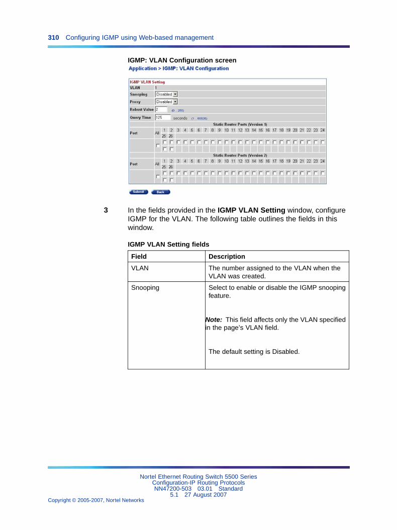
310 Configuring IGMP using Web-based management
IGMP: VLAN Configuration screen
3 In the fields provided in the IGMP VLAN Setting window, configureIGMP for the VLAN. The following table outlines the fields in thiswindow.
IGMP VLAN Setting fields
Field Description
VLAN The number assigned to the VLAN when theVLAN was created.
Snooping Select to enable or disable the IGMP snoopingfeature.
Note: This field affects only the VLAN specifiedin the page’s VLAN field.
The default setting is Disabled.
Nortel Ethernet Routing Switch 5500 SeriesConfiguration-IP Routing ProtocolsNN47200-503 03.01 Standard
5.1 27 August 2007Copyright © 2005-2007, Nortel Networks
.
Configuring IGMP using the Web-based Management Interface 311
Field Description
Proxy Select to enable or disable the Proxy feature.This feature lets the switch to consolidateIGMP Host Membership Reports receivedon its downstream ports and to generate aconsolidated proxy report for forwarding to itsupstream neighbor.
Note: This field affects only the VLAN specifiedin the page’s VLAN field.
The default setting is Disabled.
Robust Value Type the robust value in the appropriateformat. This feature lets you set the switchto offset expected packet loss on a subnet. Ifpacket losses on a subnet are unacceptablyhigh, the Robust Value field can be increasedto a higher value.
Note: This field affects only the VLAN specifiedin the page’s VLAN field.
The default setting is 2.
Query Time Type the query time (in seconds) in theappropriate format. This feature lets youcontrol the number of IGMP messages allowedon the subnet by varying the query interval(the interval between general queries sent bythe multicast router).
Note: This field affects only the VLAN specifiedin the page’s VLAN field.
The default setting is 125 seconds.
Static Router Ports(Version 1 and Version2)
Select the check boxes of the router ports toassociate with the VLAN (alternatively, selectthe check box to uncheck a selected routerport).
Nortel Ethernet Routing Switch 5500 SeriesConfiguration-IP Routing ProtocolsNN47200-503 03.01 Standard
5.1 27 August 2007Copyright © 2005-2007, Nortel Networks
.
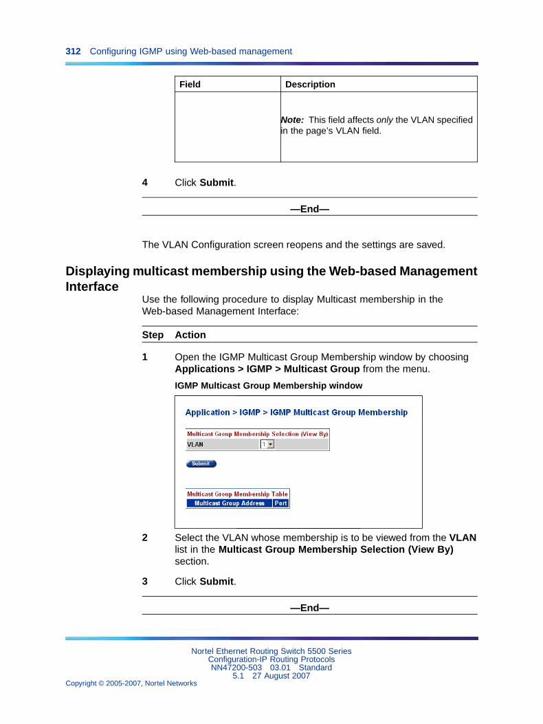
312 Configuring IGMP using Web-based management
Field Description
Note: This field affects only the VLAN specifiedin the page’s VLAN field.
4 Click Submit.
—End—
The VLAN Configuration screen reopens and the settings are saved.
Displaying multicast membership using the Web-based ManagementInterface
Use the following procedure to display Multicast membership in theWeb-based Management Interface:
Step Action
1 Open the IGMP Multicast Group Membership window by choosingApplications > IGMP > Multicast Group from the menu.
IGMP Multicast Group Membership window
2 Select the VLAN whose membership is to be viewed from the VLANlist in the Multicast Group Membership Selection (View By)section.
3 Click Submit.
—End—
Nortel Ethernet Routing Switch 5500 SeriesConfiguration-IP Routing ProtocolsNN47200-503 03.01 Standard
5.1 27 August 2007Copyright © 2005-2007, Nortel Networks
.
Displaying multicast membership using the Web-based Management Interface 313
The membership information appears in the Multicast Group MembershipTable section.
The following table describes the IGMP Multicast Group Membership pagefields.
IGMP Multicast Group Membership page fields
Section Field Description
Multicast GroupMembershipSelection (ViewBy)
VLAN Select the VLAN on which to viewconfigured IP addresses.
Multicast GroupAddress
The IP Multicast group addresses thatare currently active on the associatedport.
Multicast GroupMembership Table
Port The port numbers associated with the IPMulticast group addresses displayed inthe IP Multicast Group Address field.
Nortel Ethernet Routing Switch 5500 SeriesConfiguration-IP Routing ProtocolsNN47200-503 03.01 Standard
5.1 27 August 2007Copyright © 2005-2007, Nortel Networks
.
314
Index
AAccessing technical assistance 12An Introduction to IP Routing Protocols 13ARP 21ARP commands 64ARP configuration examples 120auto router ID 44automatic router ID assignment, if router
leaves stack 44automatic virtual link delete 244Avoiding duplicate IP addresses 44
BBrouter port 19Brouter port commands 112Brouter port screens 285
CConfiguring IGMP using Web-based
management 309Configuring IGMP with JDM 305create an automatic virtual link 243
Ddefault router ID auto assigned if router
leaves stack 44Default TTL field 210delete automatic virtual link 244DHCP commands 115DHCP forward path commandsDHCP screens 295DHCP setup 41
DHCP-BootP relay 39Documentation updates 11
EECMP 38ECMP commands 110ECMP configuration examples 204ECMP screens 284
GGlobal DHCP commands
Hhost routes 29
IIGMP configuration pages 309IGMP snooping 46, 305IGMP with the JDM 305Interface DHCP commandsIP addressing 13IP blocking 45IP routing commands 55IP Routing Configuration and
Management 51IP routing screens 209IP routing using VLANs 16
MManagement VLAN 20Multicast membership pages 312
Nortel Ethernet Routing Switch 5500 SeriesConfiguration-IP Routing ProtocolsNN47200-503 03.01 Standard
5.1 27 August 2007Copyright © 2005-2007, Nortel Networks
.
Index 315
NNon-local static routes 23
OOSPF 27OSPF commands 82OSPF configuration examples 134OSPF host route 29OSPF screens 228
PPreface 9Proxy ARP 22Proxy ARP commands 66
RReasmTimeout field 210Related publications 10RIP 23RIP commands 67RIP configuration examples 122RIP screens 222Routable VLAN commands 56Routable VLAN screens 206
Route policies 35Route policy commands 101Route policy screens 264
SSoftware updates 11stacking support 44Static route commands 59Static routes 22Subnet addressing 14Switch platforms
UUDP broadcast forwarding 38UDP broadcast forwarding commands 113UDP broadcast forwarding screens 288
Vvirtual link 31virtual link creation automatic 243VRRP 37VRRP commands 104VRRP configuration examples 190VRRP screens 277
Nortel Ethernet Routing Switch 5500 SeriesConfiguration-IP Routing ProtocolsNN47200-503 03.01 Standard
5.1 27 August 2007Copyright © 2005-2007, Nortel Networks
.

316 Index
Nortel Ethernet Routing Switch 5500 SeriesConfiguration-IP Routing ProtocolsNN47200-503 03.01 Standard
5.1 27 August 2007Copyright © 2005-2007, Nortel Networks
.

Nortel Ethernet Routing Switch 5500 Series
Configuration-IP Routing ProtocolsCopyright © 2005-2007 , Nortel NetworksAll Rights Reserved.
Publication: NN47200-503Document status: StandardDocument version: 03.01Document date: 27 August 2007
To provide feedback, or report a problem in this document, go to http://www.nortel.com/documentfeedback.
Sourced in Canada and the United States of America.
The information in this document is subject to change without notice. Nortel Networks reserves the right to make changes in designor components as progress in engineering and manufacturing may warrant.
*Nortel, Nortel Networks, the Nortel logo, and the Globemark are trademarks of Nortel Networks.