northeast usa - pennsylvania state · pdf filenortheast usa cadell g. calkins ......
TRANSCRIPT
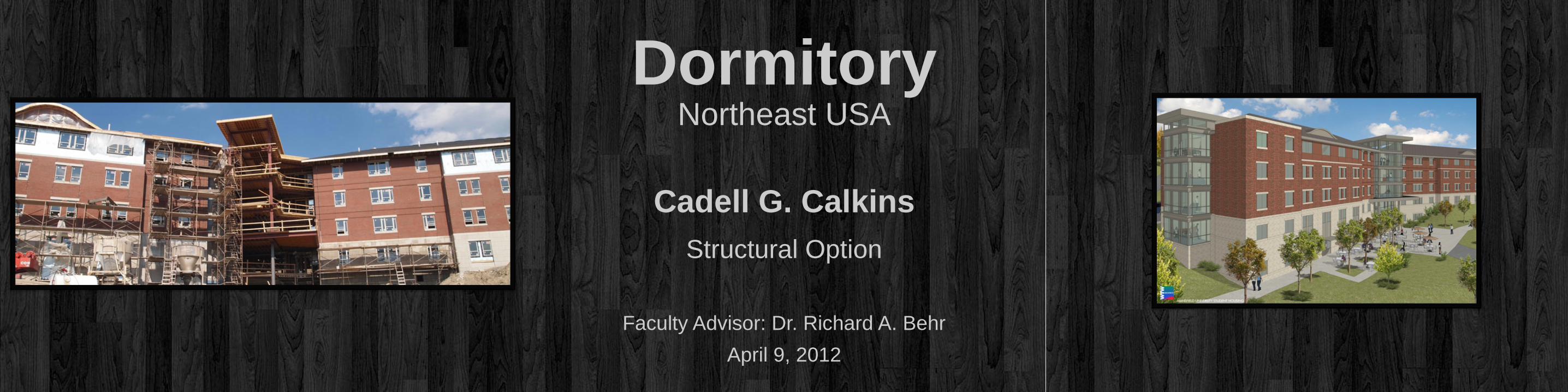
Dormitory Northeast USA
Cadell G. Calkins
Structural Option
Faculty Advisor: Dr. Richard A. Behr
April 9, 2012
Building Introduction
• Introduction • Existing Structural System • Problem Statement • Proposed Solution • Oriented Strand Board Shear Walls • Steel Braced Frame Shear Walls • Comparison of Lateral Systems • Electrical Breadth • Façade Breadth • Conclusion
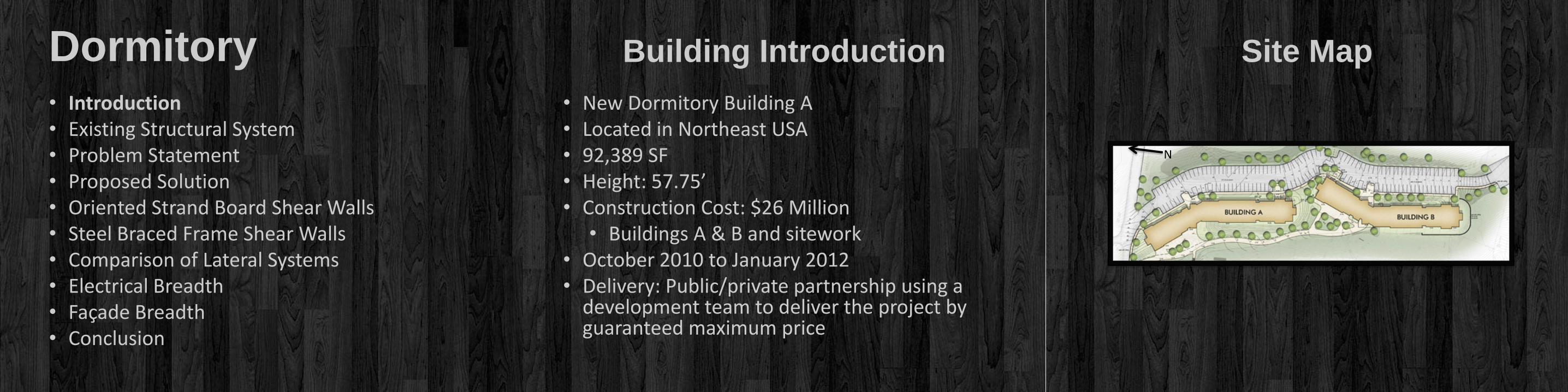
Dormitory • New Dormitory Building A • Located in Northeast USA • 92,389 SF • Height: 57.75’ • Construction Cost: $26 Million
• Buildings A & B and sitework • October 2010 to January 2012 • Delivery: Public/private partnership using a
development team to deliver the project by guaranteed maximum price
Site Map
N

Project Team
• Introduction • Existing Structural System • Problem Statement • Proposed Solution • Oriented Strand Board Shear Walls • Steel Braced Frame Shear Walls • Comparison of Lateral Systems • Electrical Breadth • Façade Breadth • Conclusion
Dormitory • Owner: Nonprofit Corporation
• Architect: WTW Architects
• Construction Manager: Massaro Corporation
• MEP, Telecom, and Security Engineer: H. F. Lenz Company
• Structural Engineer: Taylor Structural Engineers, Inc.
• Landscape Architect: LaQuatra Bonci Associates
• Developer: Allen & O’Hara Development Co. LLC
South Wing

Architecture
• Introduction • Existing Structural System • Problem Statement • Proposed Solution • Oriented Strand Board Shear Walls • Steel Braced Frame Shear Walls • Comparison of Lateral Systems • Electrical Breadth • Façade Breadth • Conclusion
Dormitory • Wings
• Suite Style Rooms • Brick and Ground Face CMU • Hip Roof with Asphalt Shingles • Sweeping Dormer Accents
• Core
• Student Gathering Spaces • Large, Storefront Windows • Flat Roof • Sun Shades
Central Core
Existing Structural System
• Introduction • Existing Structural System • Problem Statement • Proposed Solution • Oriented Strand Board Shear Walls • Steel Braced Frame Shear Walls • Comparison of Lateral Systems • Electrical Breadth • Façade Breadth • Conclusion
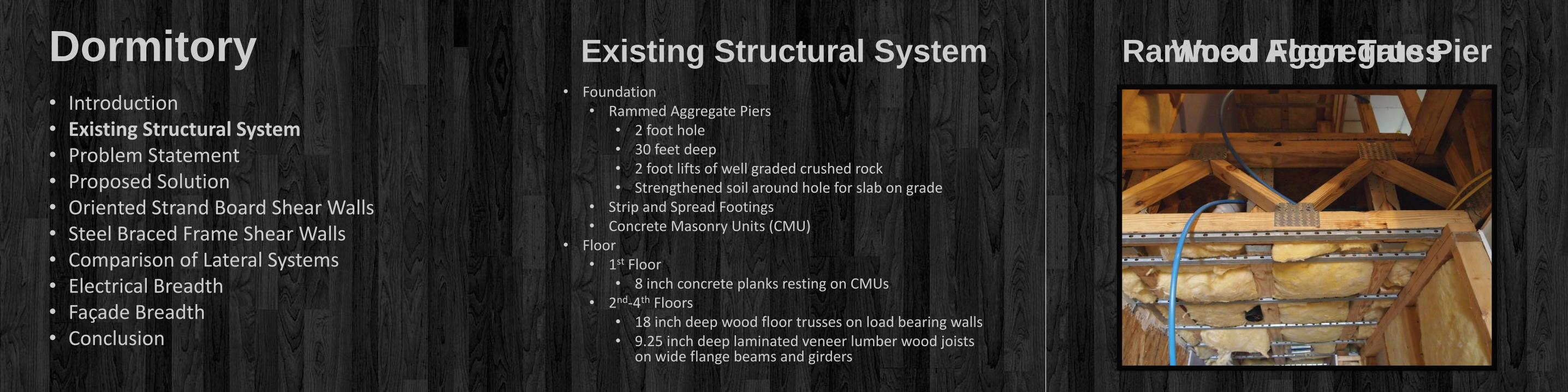
Dormitory • Foundation
• Rammed Aggregate Piers • 2 foot hole • 30 feet deep • 2 foot lifts of well graded crushed rock • Strengthened soil around hole for slab on grade
• Strip and Spread Footings • Concrete Masonry Units (CMU)
• Floor • 1st Floor
• 8 inch concrete planks resting on CMUs • 2nd-4th Floors
• 18 inch deep wood floor trusses on load bearing walls • 9.25 inch deep laminated veneer lumber wood joists
on wide flange beams and girders
Wood Floor Truss Rammed Aggregate Pier
http://sentezinsaat.com.tr/en/geopier-system.html
Existing Structural System
• Introduction • Existing Structural System • Problem Statement • Proposed Solution • Oriented Strand Board Shear Walls • Steel Braced Frame Shear Walls • Comparison of Lateral Systems • Electrical Breadth • Façade Breadth • Conclusion
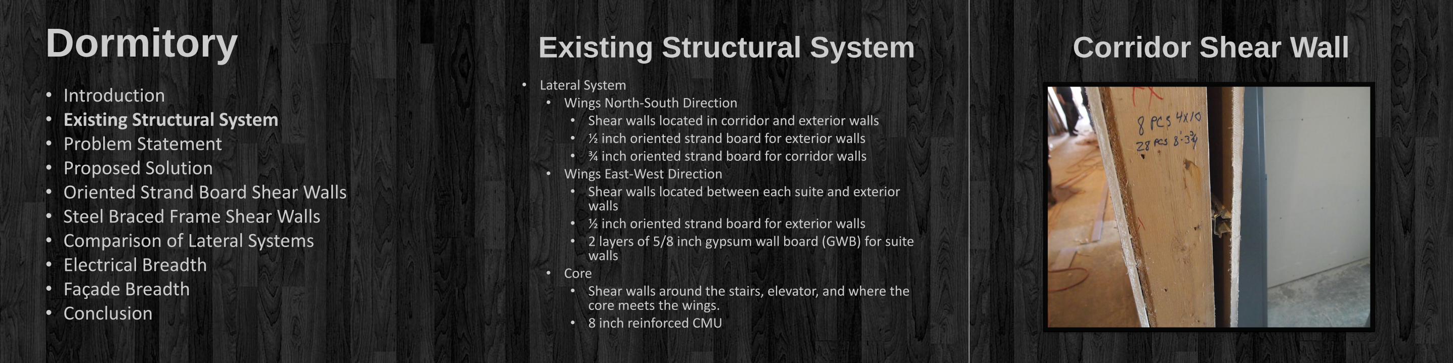
Dormitory • Lateral System
• Wings North-South Direction • Shear walls located in corridor and exterior walls • ½ inch oriented strand board for exterior walls • ¾ inch oriented strand board for corridor walls
• Wings East-West Direction • Shear walls located between each suite and exterior
walls • ½ inch oriented strand board for exterior walls • 2 layers of 5/8 inch gypsum wall board (GWB) for suite
walls • Core
• Shear walls around the stairs, elevator, and where the core meets the wings.
• 8 inch reinforced CMU
Corridor Shear Wall

Problem Statement
• Introduction • Existing Structural System • Problem Statement • Proposed Solution • Oriented Strand Board Shear Walls • Steel Braced Frame Shear Walls • Comparison of Lateral Systems • Electrical Breadth • Façade Breadth • Conclusion
Dormitory • Global Warming might soon be a design
consideration for a structural engineer.
• According to the National Wildlife Federation, the maximum hurricane wind speeds are expected to increase 2 to 13 percent within this century.
• In regards to the Dormitory,
• Original Design 90 mph (ASCE 7-05) or 115 mph (ASCE 7-10)
• Increase to 102 mph or 130 mph, respectively
• To understand this new loading, the following situation has been created.
• State College of Florida, Manatee-Sarasota (SCF) would like to build the Dormitory. In this area, the design wind speed is 150 mph.
• SCF has required that the Dormitory be capable of withstanding:
• wind pressures due to hurricanes and tornadoes
• debris impacts on the façade
• foundation for the sandy soil
Proposed Solution
• Introduction • Existing Structural System • Problem Statement • Proposed Solution • Oriented Strand Board Shear Walls • Steel Braced Frame Shear Walls • Comparison of Lateral Systems • Electrical Breadth • Façade Breadth • Conclusion
Dormitory Problem Statement
• Lateral System in Wings: • Oriented strand board (OSB) shear walls • Steel braced frame shear walls
• Lateral System in Core • Steel braced frame shear walls
• Gravity System • Steel deck and joist floors • Steel wide flange beams and columns
• Foundation • Strip and spread footings
• To understand this new loading, the following situation has been created.
• State College of Florida, Manatee-Sarasota (SCF) would like to build the Dormitory. In this area, the design wind speed is 150 mph.
• SCF has required that the Dormitory be capable of withstanding:
• wind pressures due to hurricanes and tornadoes
• debris impacts on the façade
• foundation for the sandy soil

Shear Wall Design
• Introduction • Existing Structural System • Problem Statement • Proposed Solution • Oriented Strand Board Shear Walls • Steel Braced Frame Shear Walls • Comparison of Lateral Systems • Electrical Breadth • Façade Breadth • Conclusion
Dormitory • 1st Floor Shear Wall Design • North – South Winds
• Original Design Satisfactory • ¾ inch OSB corridor walls • ½ inch OSB exterior walls
• Maximum Deflection = 0.17 in < L/360 = 0.3 in • East – West Winds
• GWB Insufficient • Use 5/16 in OSB with 3 in edge fastener
spacing • Maximum Deflection = 0.26 in < L/360 = 0.3 in
Oriented Strand Board
N

Shear Wall Design Dormitory
• North – South Winds
• Maximum Deflection
• 0.19 in < L/360 = 0.30 in
• Columns – W8x31
• Braces – L2x2x1/8 – L2x2x5/16
• Beams – W12x35
Steel Braced Frames
N
N

Shear Wall Design Dormitory
• East – West Winds
• Maximum Deflection
• 0.08 in < L/360 = 0.30 in
• Columns – W8x31
• Braces – L2x2x1/8 – L2x2x1/4
• Beams – W12x30 – W12x35
Steel Braced Frames
N
N
Shear Wall Design
• Introduction • Existing Structural System • Problem Statement • Proposed Solution • Oriented Strand Board Shear Walls • Steel Braced Frame Shear Walls • Comparison of Lateral Systems • Electrical Breadth • Façade Breadth • Conclusion
Dormitory
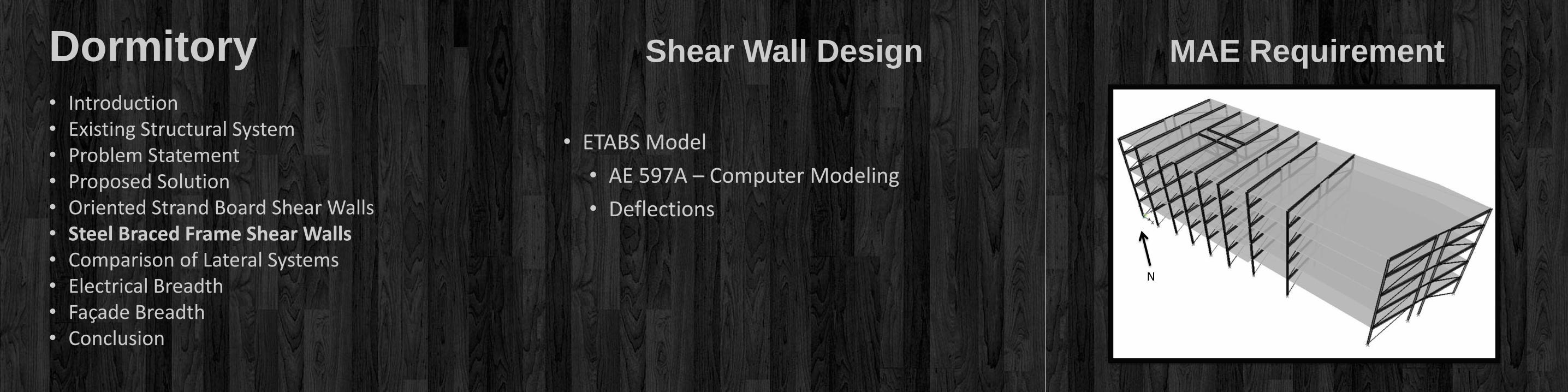
• ETABS Model
• AE 597A – Computer Modeling
• Deflections
MAE Requirement
N

Shear Wall Design
• Introduction • Existing Structural System • Problem Statement • Proposed Solution • Oriented Strand Board Shear Walls • Steel Braced Frame Shear Walls • Comparison of Lateral Systems • Electrical Breadth • Façade Breadth • Conclusion
Dormitory
• Braced Frame Connection
• AE 534 – Steel Connections
• 4 inch wide, ¼ inch A36 plate
• (2) 1/8 inch welds, 5 inches long
• (2) 1/16 inch welds, 9 inches long
MAE Requirement

Lateral System Comparison
• Introduction • Existing Structural System • Problem Statement • Proposed Solution • Oriented Strand Board Shear Walls • Steel Braced Frame Shear Walls • Comparison of Lateral Systems • Electrical Breadth • Façade Breadth • Conclusion
Dormitory Steel Braced Frames
System Gravity Walls Total
OSB Shear Wall $1,228,000 $288,000 $1.516 million
Steel Braced Frame $1,072,000 $261,000 $1.333 million
System Drift at Roof
(inches)
h/400
(inches)
OSB Shear Wall E-W 1.30 1.47
Steel Braced Frame E-W 0.32 1.47
OSB Shear Wall N-S 0.86 1.47
Steel Braced Frame N-S 0.75 1.47
Electrical Breadth
• Introduction • Existing Structural System • Problem Statement • Proposed Solution • Oriented Strand Board Shear Walls • Steel Braced Frame Shear Walls • Comparison of Lateral Systems • Electrical Breadth • Façade Breadth • Conclusion
Dormitory
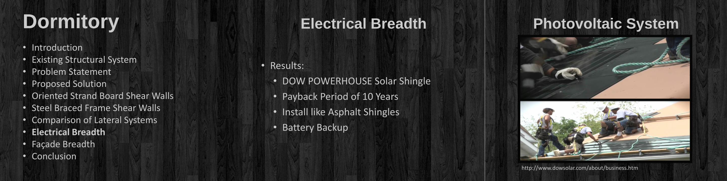
• Results:
• DOW POWERHOUSE Solar Shingle
• Payback Period of 10 Years
• Install like Asphalt Shingles
• Battery Backup
Photovoltaic System
http://www.dowsolar.com/about/business.htm

Façade Breadth
• Introduction • Existing Structural System • Problem Statement • Proposed Solution • Oriented Strand Board Shear Walls • Steel Braced Frame Shear Walls • Comparison of Lateral Systems • Electrical Breadth • Façade Breadth • Conclusion
Dormitory • Rain Screen Wall Cladding System
• American Fiber Cement Corporation’s Textura
• R-value and condensation analysis using H.A.M.
• Impact Resistant
• “This product has been designed and tested to comply with the Requirements of the Florida Building Code 2010 edition including High Velocity Hurricane Zone (HVHZ), TAS 202 and TAS 203”
Rain Screen
http://www.americanfibercement.com/textura

Conclusion
• Introduction • Existing Structural System • Problem Statement • Proposed Solution • Oriented Strand Board Shear Walls • Steel Braced Frame Shear Walls • Comparison of Lateral Systems • Electrical Breadth • Façade Breadth • Conclusion
Dormitory
• Lateral System Comparison
• Oriented strand board
• Steel braced frame
• Solar Shingles
• Rain Screen Cladding
Recommendation
• Steel braced frame system
• Steel floor and gravity system
Acknowledgements
• Introduction • Existing Structural System • Problem Statement • Proposed Solution • Oriented Strand Board Shear Walls • Steel Braced Frame Shear Walls • Comparison of Lateral Systems • Electrical Breadth • Façade Breadth • Conclusion
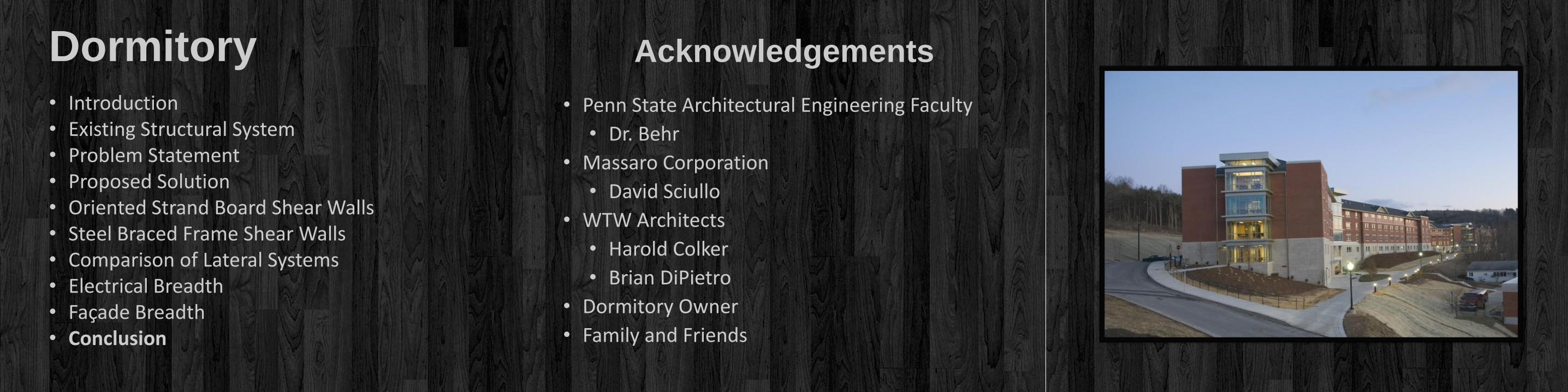
Dormitory • Penn State Architectural Engineering Faculty
• Dr. Behr
• Massaro Corporation
• David Sciullo
• WTW Architects
• Harold Colker
• Brian DiPietro
• Dormitory Owner
• Family and Friends

Questions and Comments
• Introduction • Existing Structural System • Problem Statement • Proposed Solution • Oriented Strand Board Shear Walls • Steel Braced Frame Shear Walls • Comparison of Lateral Systems • Electrical Breadth • Façade Breadth • Conclusion
Dormitory