northern sea route reconnaissance study
TRANSCRIPT

SPEC
IAL
REP
OR
T9
5-1
7
Northern Sea RouteReconnaissance StudyA Summary of Icebreaking TechnologyDevinder S. Sodhi June 1995

AbstractSince the advent of steam power, icebreakers have been built to navigate inice-covered waters. The hull forms of early icebreakers were merely anadaptation of open water hull shapes, by sloping bow angles more tocreate vertical forces for breaking ice in bending. However, these bow formswere found to be unsuitable for sea-going vessels because they push bro-ken ice ahead of them. This experience led to construction of all sea-goingvessels with wedge-shaped bows from 1901 to 1979. With the introduc-tion of low-friction coatings and the water-deluge system, it is now possibleto operate ships with blunt bows efficiently in broken ice. New develop-ments in marine propulsion technology have also been incorporated toobtain better icebreaking efficiency and performance. Both fixed-pitch andcontrollable-pitch propellers are in use. Nozzles surrounding the propellersare also used to increase the thrust and to reduce ice–propeller interaction.Electrical and mechanical transmission systems have been used in ice-breakers to improve the characteristics of the propulsion system. Thoughmany types of prime movers are used in icebreakers, medium-speed dieselengines are the most popular because of their overall economy and reli-ability. Appendix A is a description of the Russian icebreaker Yamal, whichis one of the largest and most powerful icebreakers of the world today.Appendix B contains an inventory of existing ships that are capable ofnavigating in at least 0.3-m-thick ice. Some of the present icebreakers arecapable of navigating almost anywhere in the ice-covered waters of theArctic and the Antarctic, and multi-purpose icebreakers have been built tooperate not only in ice during the winter but also in open water doing othertasks during the summer. With sufficient displacement, power, navigationequipment, and auxiliary systems, future icebreakers that can operate in-dependently year-round in the Arctic and the Antarctic are well within theknown technology and operational experience.
For conversion of SI units to non-SI units of measurement consult ASTMStandard E380-93, Standard Practice for Use of the International Systemof Units, published by the American Society for Testing and Materials,1916 Race St., Philadelphia, Pa. 19103.
This report is printed on paper that contains a minimum of 50% recycledmaterial.

Special Report 95-17
Northern Sea RouteReconnaissance StudyA Summary of Icebreaking TechnologyDevinder S. Sodhi June 1995
Prepared for
U.S. ARMY ENGINEER DISTRICT, ALASKA
Approved for public release; distribution is unlimited.
US Army Corpsof EngineersCold Regions Research &Engineering Laboratory

PREFACE
This report was written by Dr. Devinder S. Sodhi, Research Engineer, Ice EngineeringResearch Division, Research and Engineering Directorate, U.S. Army Cold Regions Re-search and Engineering Laboratory. It represents a part of the investigations supporting aReconnaissance Study of the Northern Sea Route. The project was funded by the U.S. ArmyEngineer District, Alaska. Dr. Orson Smith was the Project Manager.
The author is indebted to Leonid Tunik and Alfred Tunik for compiling the informationon icebreakers (presented in Appendix B); Captain Lawson Brigham, Commanding Of-ficer of the USCG Polar Sea, for providing information, photographs, suggestions, andvaluable background material; Dr. Jean-Claude Tatinclaux, Chief, Ice Engineering ResearchDivision, for providing many references and for reviewing this report; Kevin Carey, Re-search Hydraulic Engineer, Ice Engineering Research Division, for technically reviewingthe manuscript; and Walter B. Tucker, III, Chief of the Snow and Ice Division, for providinginformation on, and photographs of, the icebreakers at the North Pole. The author thanksthe members of the Reconnaissance Study team for their guidance and suggestions.
The author also gratefully acknowledges the dedicated work of the following CRRELpersonnel in the preparation of this report: Nancy Liston and Elizabeth Smallidge forprocurement of publications and reports, Matthew Pacillo and Edward Perkins for prepara-tion of the figures, and Lourie Herrin for typing assistance.
The contents of this report are not to be used for advertising or promotional purposes.Citation of brand names does not constitute an official endorsement or approval of the useof such commercial products.
ii

CONTENTSPage
Preface ................................................................................................................................ iiIntroduction ........................................................................................................................ 1
Early history ................................................................................................................ 1Recent history ............................................................................................................. 5
Inventory of icebreaking ships ........................................................................................ 6Sizes and dimensions ........................................................................................................ 7
Beam ........................................................................................................................... 7Depth ........................................................................................................................... 7Draft ........................................................................................................................... 7Maximum deadweight .............................................................................................. 7
Hull forms........................................................................................................................... 8Bow shape ................................................................................................................... 8Midbody shape ........................................................................................................... 10Stern shape .................................................................................................................. 10Icebreaker performance with different hull forms ............................................... 11
Structural design of polar ships ...................................................................................... 12Classification of polar ships ..................................................................................... 12Ice loads and pressures ............................................................................................. 12Materials ...................................................................................................................... 13Welding ........................................................................................................................ 14Plating .......................................................................................................................... 14Framing ........................................................................................................................ 14
Propulsion system ............................................................................................................. 15Propellers ..................................................................................................................... 16Shafting ........................................................................................................................ 17Mechanical transmission components .................................................................... 17Electrical transmission systems ............................................................................... 17Azimuth propulsion drive ........................................................................................ 18Prime movers .............................................................................................................. 19
Auxiliary systems .............................................................................................................. 21Low-friction hull coating .......................................................................................... 21Heeling system ........................................................................................................... 22Air-bubbler system .................................................................................................... 22Air-bubbler–water injection system ........................................................................ 23Water-deluge system ................................................................................................. 23
Power and performance ................................................................................................... 23Fuel consumption rates ............................................................................................. 23Performance prediction ............................................................................................. 24
Future icebreakers ............................................................................................................. 28Summary ............................................................................................................................. 30Literature cited ................................................................................................................... 30Appendix A: Information about the nuclear icebreaker Yamal .................................. 33Appendix B: An inventory of existing ships that are capable of navigating in
at least 0.3-m-thick ice cover ............................................................................. 35
iii

ILLUSTRATIONS
Figure Page
1. The Russian icebreaker Yamal, the Canadian icebreaker Louis S. St. Laurent,and the U.S. icebreaker Polar Sea during the expedition to theNorth Pole in August of 1994 ......................................................................... 3
2. Significant events in the development of polar ship technololgysince 1955 ........................................................................................................... 4
3. Design evolution of Russian polar icebreakers ................................................ 54. Taymyr-class shallow-draft nuclear icebreaker ................................................. 65. Dimensions of vessels ........................................................................................... 76. Maximum deadweight vs. overall length of all vessels listed in
Appendix B ........................................................................................................ 87. Main features of bow forms ................................................................................. 98. Different shapes of icebreaking bows ................................................................ 99. Hull form of the Finnish multipurpose icebreakers Finnica and
Nordica ................................................................................................................ 1010. Icebreaking capabilities of three sister ships with different bow
shapes in terms of speeds in level ice of different thicknessesat a power level of 16.2 MW ........................................................................... 11
11. Ship speed vs. equivalent ice thickness during tests in broken icewith three sister ships having different bow shapes .................................. 11
12. Measured effective pressure vs. contact area .................................................... 1313. Plane strain fracture toughness vs. temperature for two grades of steel ..... 1314. Pressure vs. deflection, showing domains of different behaviors from
small to large deflection .................................................................................. 1415. Shaft power vs. year of construction for icebreaking ships ........................... 1516. Shaft power vs. propeller diameter for icebreaking ships .............................. 1617. Differences between diesel-mechanical and azimuth installations .............. 1918. Prime movers installed on icebreaking ships ................................................... 1919. Outboard profile and topside deck plan of the Swedish icebreaker
Oden .................................................................................................................... 2220. Power vs. beam for icebreakers .......................................................................... 2321. Icebreaking performance: bollard pull/beam vs. ice thickness .................... 2322. Speeds and power levels of U.S. icebreaker Polar Sea during her
transit from 23 March to 4 April 1983 ........................................................... 2523. Number of ramming operations during the transit of U.S. icebreaker
Polar Sea from 23 March to 4 April 1983 ........................................................ 2624. Specific net thrust vs. speed at maximum shaft power, indicating
propulsive performance .................................................................................. 2725. New “iceraking” concept, as proposed by Johansson et al. ........................... 29
TABLES
Table1. Selected important icebreaking voyages in recent years ................................ 22. Estimates of daily fuel consumption for a Polar-class icebreaker .................. 243. Fuel consumption rates of a few Russian ships according to the
information given in the brochures of the Murmansk ShippingCompany ............................................................................................................ 24
4. Performance criteria for a Northwest Passage icebreaker .............................. 285. Comparison of design parameters of proposed Northwest Passage
icebreaker with those of the Yamal ................................................................. 28
vi

INTRODUCTION
In the last four to five decades, many develop-ments in icebreaking technology have taken placethrough the application of modern marine tech-nology to the design and the operation of polarships. Innovative ideas have been implemented toimprove the propulsion systems and to reduce theresistance encountered during icebreaking. Presentnavigation and information systems (e.g., ice maps,satellite images, etc.) aboard polar ships enablenavigators to identify ice features along the tran-sit route in near real time and to chart a tacticalcourse. As a result of this, it is possible to travel byships to remote polar regions that were thought tobe unreachable only a few years ago. Many na-tions have contributed to this development by de-signing and building polar ships and by launch-ing voyages to various regions of the Arctic andthe Antarctic. Some of the landmark voyages dur-ing the last four decades are listed in Table 1(Brigham 1992). Recently, Russian nuclear-pow-ered icebreakers have regularly traveled to theNorth Pole. In August of 1994, the U.S. icebreakerPolar Sea, the Canadian icebreaker Louis S. St.Laurent and the Russian nuclear icebreaker Yamal(App. A) met at the North Pole (Fig. 1).
The impetus behind these technological ad-vances has come from:
1. The exploration for natural resources aroundthe Arctic Basin.
2. The development of the Northern Sea Routeby the former Soviet Union, as an integralpart of development of the entire RussianArctic.
3. The need for multi-mission ships for thetransportation of personnel, logistics andmarine research in the Antarctic.
Although exploration for hydrocarbon re-sources in the southern Beaufort Sea has almost
stopped, plans are being discussed for develop-ments in the offshore areas of the Russian Arcticto produce hydrocarbon resources and to trans-port them to world markets. Future shipments ofthese resources will have significant effects on thedevelopment of the Northern Sea Route.
From the perspectives of a master mariner, theperformance of icebreakers depends on the con-struction limitations of the vessels and the skillsin ice navigation of their captains (Toomey 1994).Although the technological improvements incor-porated in the design and construction of an ice-breaker help to increase its performance in ice, itis essential to have a skilled captain and crew op-erating the ship to exploit these advantages to themaximum extent. Therefore, the training and theexperience of the crew operating an icebreaker areimportant elements in its performance. A knowl-edgeable, skilled captain, supported by extensiveinformation, can prevent or quickly overcomemany difficulties along a route.
Early historyJohansson et al. (1994) have given an account of
the early history of icebreaking ships. Breaking icewith ships was not possible before the advent ofsteam power. One of the earliest icebreakers,named Norwich, was introduced in 1836 on theHudson River. She had paddle wheels for propul-sion and was very effective in breaking ice, remain-ing in service for 87 years.
By the end of the nineteenth century, only fixed-pitch, screw-type propellers driven with steampower were installed on new icebreakers. Earlyicebreakers were not powerful, and the hull formwas basically adapted from open water hull shapesby sloping the bow angles more to create a verti-cal force to break the ice in bending. Many inno-vative designs were proposed and built to increaseicebreaking efficiency. For instance, the highly suc-
Northern Sea Route Reconnaissance StudyA Summary of Icebreaking Technology
DEVINDER S. SODHI

Table 1. Selected important icebreaking voyages in recent years (after Brigham 1992).
Polar ship/flag Time of year Route/location Significance
Lenin Summer 1960 Northern Sea Route World’s first nuclear surface ship com-USSR mences icebreaking escort duties
Manhattan Autumn 1969 Northwest Passage Experimental voyages to test the feasi-USA bility of commercial tankers in the Arctic
Louis S. St.Laurent and Aug 1976 Northwest Passage Successful escort of a drill ship from theCanmar Explorer II Atlantic to the Canadian Beaufort Sea
Canada
Arktika Aug 1977 Murmansk to the North First surface ship to reach the geographicUSSR Pole and return North Pole (17 Aug)
Sibir’ and Kapitan Myshevskiy May–Jun 1978 Northern Sea Route (north First high-latitude “trans-Arctic” ice escortUSSR of Novosibirskiy Islands)
Polar icebreakers and Navigation season Barents and Kara seas First successful year-round navigation fromicebreaking carriers 1978–79 Murmansk to Dudinka on the Yenisey River
USSR
Polar Star and Polar Sea 1979–86 Bering, Chukchi, and Arctic marine transportation (“traffic-USA Beaufort seas ability”) studies around Alaska
Polar Sea Jan–Mar 1981 Bering Sea to Beaufort Sea First winter transit to Pt. Barrow, AlaskaUSA
Polar Star Dec 1982–Mar 1983 Antarctica First high-latitude (above 60°S) circum-USA navigation of Antarctica in modern times
Leonid Brezhnev and Oct–Nov 1983 North coast of Chukotka, Rescue of 50 cargo ships trapped in ice12 other icebreakers Siberia
USSR
Arctic Aug 1985 Bent Horn, Cameron First cargo of crude oil from theCanada Island Canadian Arctic
Vladivostok and Somov Jun–Sep 1985? Near Russkaya Station, Rescue of Soviet Antarctic ExpeditionUSSR Hobbs Coast, Antarctica flagship drifting in heavy ice
Three SA-15 icebreaking Nov–Dec 1985 Northern Sea Route Experimental navigation season ex-carriers tension with sailings from Vancouver
USSR to Arkangel’sk
Icebird Fall 1985– Australian Antarctic Bipolar resupply operations toFRG Summer 1986 stations and Japan to Antarctica and Prudhoe Bay
Prudhoe Bay, Alaska
Polarstern Jul–Aug 1986 Weddell Sea, Antarctica Winter oceanographic operationsFRG
Sibir’ May–Jun 1987 Central Arctic Basin Evacuate drift station 27 and establishUSSR drift station 29; second surface ship to
reach the geographic North Pole (25 May)
SA-15 icebreaking Summer 1989 Europe to Japan via the Soviet arctic carriers under charter tocarriers Northern Sea Route Western shippers for commmercial voy-
USSR ages across the top of the Soviet Union
Rossiya Aug 1990 Central Arctic Basin Transit to the North Pole (8 Aug) withUSSR Western tourists aboard
Arctic Jun 1991 Northwest Passage to the Earliest seasonal surface ship transitCanada Polaris Mine, Little in eastern reaches of the Northwest
Cornwallis Island Passages; mine reached 23 Jun
Sovetskiy Soyuz Jul–Sep 1991 Central Arctic Basin and Transit to the North Pole and along theUSSR Northern Sea Route Northern Sea Route with Western tourists
Oden and Polarstern Aug 1991 Central Arctic Basin International Arctic Ocean Expedition;Sweden and FRG reached the North Pole on 7 Sep
Sovetskiy Soyuz Jul and Aug 1992 Central Arctic Basin Reached the North Pole on 13 Jul andRussia 23 Aug
Yamal Jul and Aug 1993 Central Arctic Basin Reached the North Pole three timesRussia on 13 Jul, 8 and 30 Aug
Yamal and Kapitan Branitsyn Jul 1994 Central Arctic Basin Reached the North Pole on 21 JulRussia
Yamal Aug 1994 Central Arctic Basin Reached the North Pole on 5 and 20 AugRussia
Louis S. St. Laurent and Polar Sea Aug 1994 Trans-Arctic Ocean Reached the North Pole on 22 Aug;Canada and USA Bering Strait to Svalbard encountered Yamal at the North Pole
2

a. Near the North Pole.
b. View from Yamal (Polar Sea is last in line).
Figure 1. The Russian icebreaker Yamal, the Canadian icebreaker Louis S. St. Laurent, and the U.S.icebreaker Polar Sea during the expedition to the North Pole in August of 1994 (photos courtesy W.B.Tucker, III).
3

4
Figu
re 2
. Sig
nific
ant e
vent
s in
the
deve
lopm
ent o
f pol
ar s
hip
tech
nolo
gy s
ince
195
5 (a
fter
Bri
gham
198
7).
Bo
w

Recent historyFigure 2 shows a summary of significant ad-
vances in the polar ship technology during the pastfour decades, as outlined by Brigham (1987), madeby Finland and the former Soviet Union, and bythe U.S., Canada, Germany and Japan. Together, Fin-land and the Soviet Union have made enormouscontributions to the development of polar ships.
The Soviet Union first used nuclear technologyto power the icebreaker Lenin, which was built in1959 with a propulsive power of 29 MW (39,000hp). The Finnish shipbuilder, Wärtsilä Shipyard(now Kværner Masa-Yards), built many icebreak-ers for the Soviet Union and created extensive de-sign evolution during the years of the developmentof conventionally powered icebreakers. Recently,these two technologies have merged, as shown inFigure 3, to develop the Taymyr-class (Fig. 4), shal-low-draft polar icebreakers built in Helsinki withSoviet nuclear propulsion systems installed in St.Petersburg.
Similarly, developments in the U.S. and Canadahave contributed to changes in key areas of ice-breaking technology (e.g., hull and bow form, gasturbines, and controllable-pitch propellers). In1969, the U.S. modified tanker Manhattan had ten-fold the displacement of earlier icebreakers, giv-ing her great ramming capability. In the early1980’s, modern hull and propulsion technologieswere also applied to Antarctic ships (e.g., Japan’sShirase, and Germany’s Polarstern). The bows ofthree icebreakers were converted to the newly de-veloped Thyssen-Waas bow: Max Waldeck in 1980,Mudyug in 1986 and Kapitan Sorokin in 1991. Theresults of full-scale trials in open water and in iceindicate that this change in the bow of Mudyughas increased her icebreaking capability in levelice at reduced power requirements (Milano 1987).However, there were problems with wave slam-
cessful “spoon-shaped” bow was first proposedand built by Ferdinand Steinhaus of Hamburg in1871. In 1892, Weedermann invented and patenteda device to be placed in front of a ship having abow not suitable for icebreaking on its own. Thesedevices are still used on Dutch rivers and canals.
By 1900, it was well understood that, while shipswith blunt bows are efficient in breaking level icein sheltered areas, such as rivers, lakes and otherprotected areas, their performance in rubble ice ispoor because they have a tendency to push bro-ken ice ahead of themselves. On the other hand,ships with wedge-shaped bows and sharp stemsdid not have any tendency to push rubble ice. Thisexperience led to all sea-going ships built between1901 and 1979 having a wedged-shaped bow anda sharp stem (Johansson et al. 1994). Over the years,the wedge-shaped bows became known as “con-ventional” bows, and the other shapes as “uncon-ventional” bows.
The development of the bow form remainedstagnant in the early and middle part of the 20thcentury (Johansson et al. 1994). This can be attrib-uted partly to other priorities caused by the twoWorld Wars and by the slowdown of economicacivity during the large-scale recession of the 1930s.Despite this stagnancy in bow design, other inno-vations were introduced during this time. The Rus-sian icebreaker Yermak, built in 1899 and fittedwith propulsive machinery of 7.46 MW (10,000hp), had considerable effect on the icebreakingtechnology at the turn of this century by becom-ing a pioneer in many untested offshore areas. In1933, diesel-electric propulsion was introduced onthe Swedish icebreaker Ymer. In 1947, twin bowpropellers were introduced on the Canadian ice-breaking ferry Abgeweit. (However, the use ofbow propellers has now been discontinued be-cause of their interference with ice.)
Figure 3. Design evolution of Russian polar icebreakers (after Brigham 1991).
5

icebreaking ships and multi-purpose ships will bedictated by the needs of future developments andtrade.
INVENTORY OFICEBREAKING SHIPS
Icebreaking ships that will be built in the futuremay have their designs based on the present stateof icebreaking technology and may also incorpo-rate innovative developments in many areas ofmarine technology. Past experience can help de-signers avoid mistakes, but accepting the presentstatus too rigidly can also discourage them frominnovation. Improvements in the design of ice-breakers should result from a full understandingof the current status of icebreaking technology.
Information on most of the icebreaking ships inthe world is given in the appendix of the reviewpaper by Dick and Laframboise (1989), and anupdated and a modified version of this list is alsoincluded in the appendix of a report by Mulherinet al. (1994). The latter database contains informa-tion on icebreakers and icebreaking cargo shipsfrom the following countries: Argentina, Canada,Denmark, Finland, Japan, Sweden, United King-dom, Russia (or former Soviet Union), U.S. andGermany.
An inventory of all ships that are capable ofnavigation in at least 0.3-m- (1-ft-) thick ice hasbeen prepared for this study. This information hasbeen assembled in an electronic database and isalso presented in Appendix B. The database con-
ming in open water operations during high seas,and with the front of the ship pushing rubble ice(Ierusalimsky and Tsoy 1994).
In 1979, the Canadian icebreaker Kigoriak wasbuilt with a spoon-shaped bow for operations inthe Beaufort Sea. Extensive full-scale experienceindicated that even this modern version of thespoon-shaped bow was not immune to the ice-pushing problem. However, these problems weresolved by using epoxy paint and a water-delugesystem to reduce friction between the broken icepieces and the hull. The water-deluge system liftsseveral tons of water every second and pours it ontop of the ice in front of the bow. This helps to movethe ice pieces past the ship by submerging them.In the early 1980s, several ships in Canada werebuilt with spoon-shaped bows. Some of the recenticebreakers built in Europe have also been builtwith these bows, e.g., the Swedish icebreaker Oden,built in 1989, the Russian icebreaker KapitanNikolayev, converted in 1990, and the Finnish ice-breakers Finnica and Nordica, built in 1993 and 1994.
With the introduction of low-friction coatingsand auxiliary systems, the capabilities of presenticebreakers are greatly enhanced so that they canmake steady progress in all types of ice conditions.With sufficient displacement, power and auxiliarysystems, future icebreakers that can operateindependently year-round in the Arctic are wellwithin the known technology and operational ex-perience (Keinonen 1994). As in the past, the con-struction of future icebreakers and icebreakingcargo ships will be closely linked to economic con-ditions and pressures. Choices between dedicated
Figure 4. Taymyr-class shallow-draft nuclear icebreaker (after Brigham 1991).
Single Pressurized Water Reactor(USSR)
2 Main Steam Turbines(USSR)
Power Unit Automationand Control System
(Finland)2 Main Generators(West Germany)
3 AC Propeller Motors(Finland)
Shallow-draftDesign (~8 meters)
(Finland)
Low FrictionHull Coating
(Finland)
Hull Air LubricationSystem
(Finland)
Ship Systems Operate atAir Temperatures to –50°C
(USSR & Finland)
Icebreaking Bow and Hull Form
(Finland)
Cold-resistantHull Steel Plates
(USSR)
6

tains technical and other forms of information oneach series of ships. Technical information consistsof length, beam, depth, draft, deadweight, dis-placement, propulsion machinery, nominal speed,bow shape, propulsion power, fuel capacity, fuelrate, etc. Non-technical information consists of thename (or former name), names of sister ships, own-ership, shipyard and year of construction, homeport, ice classification, etc.
SIZES AND DIMENSIONS
The main dimensions of a polar ship are itslength, beam width and depth. The draft is thedepth of the ship’s keel below the waterline,whereas the depth is the distance between the keeland the deck. The depth of water in which a shipcan operate without touching bottom depends onthe draft. Figure 5a shows plots of the dimensionsof icebreakers (cargo ships not included) as com-piled by Dick and Laframboise (1989), whereas Fig-ure 5b shows the dimensions of all ships as com-piled in the database given in Appendix B. Thescatter in the plot of data in Figure 5b is greaterthan that in Figure 5a, because ships listed in Ap-pendix B are not only icebreakers but also otherships having some icebreaking capability. Thetrends of the lines shown in Figure 5a pertain onlyto icebreakers, whereas the lines of best fit shownin Figure 5b pertain to the data on vessels listed inAppendix B.
BeamIn Figure 5a, the mean length-to-beam ratio of
icebreakers varies from 3.6 to 4.6 for lengths from40 to 140 m respectively. North American vesselsare narrower than those from Finland, Sweden andRussia. This may be attributed to the practice ofconvoy escort used in the Baltic Sea and RussianArctic. The line of best fit in Figure 5b has an inter-cept of 6.7 m and a slope of 0.102 m/m.
DepthIn Figure 5a, the mean length-to-depth ratio of
icebreakers varies from 8.9 to 8.2 for lengths from40 to 140 m respectively. This ratio is high for sup-ply vessels and low for conventional icebreakers.The line of best fit in Figure 5b has an intercept of0.6 m and a slope of 0.08 m/m.
DraftIn Figure 5a, the mean length-to-draft ratio of
icebreakers varies from 11.4 to 12.2 for lengths from
Figure 5. Dimensions of vessels.
b. All vessels included in the inventory of shipslisted in Appendix B.
40 to 140 m respectively. Draft, like other dimen-sions, is usually defined by the operating require-ments of the ship. The line of best fit in Figure 5bhas an intercept of 2.2 m and a slope of 0.042 m/m.
Maximum deadweightFigure 6 shows a plot of deadweight at maxi-
mum draft vs. the overall length of the vesselslisted in Appendix B. The curve shown in Figure 6is a best fit quadratic curve having the followingequation
40
30
20
10
0 40 80 120 160 200
Bea
m, D
epth
, Dra
ft (m
) Beam
Depth
Draft
Length (m)
a. Icebreakers (cargo ships not included) (after Dickand Laframboise 1989).
250
40
30
20
10
0
Bea
m, D
epth
, Dra
ft (m
)
50 100 150 200
Length (m)
Beam
Depth
Draft
0
7
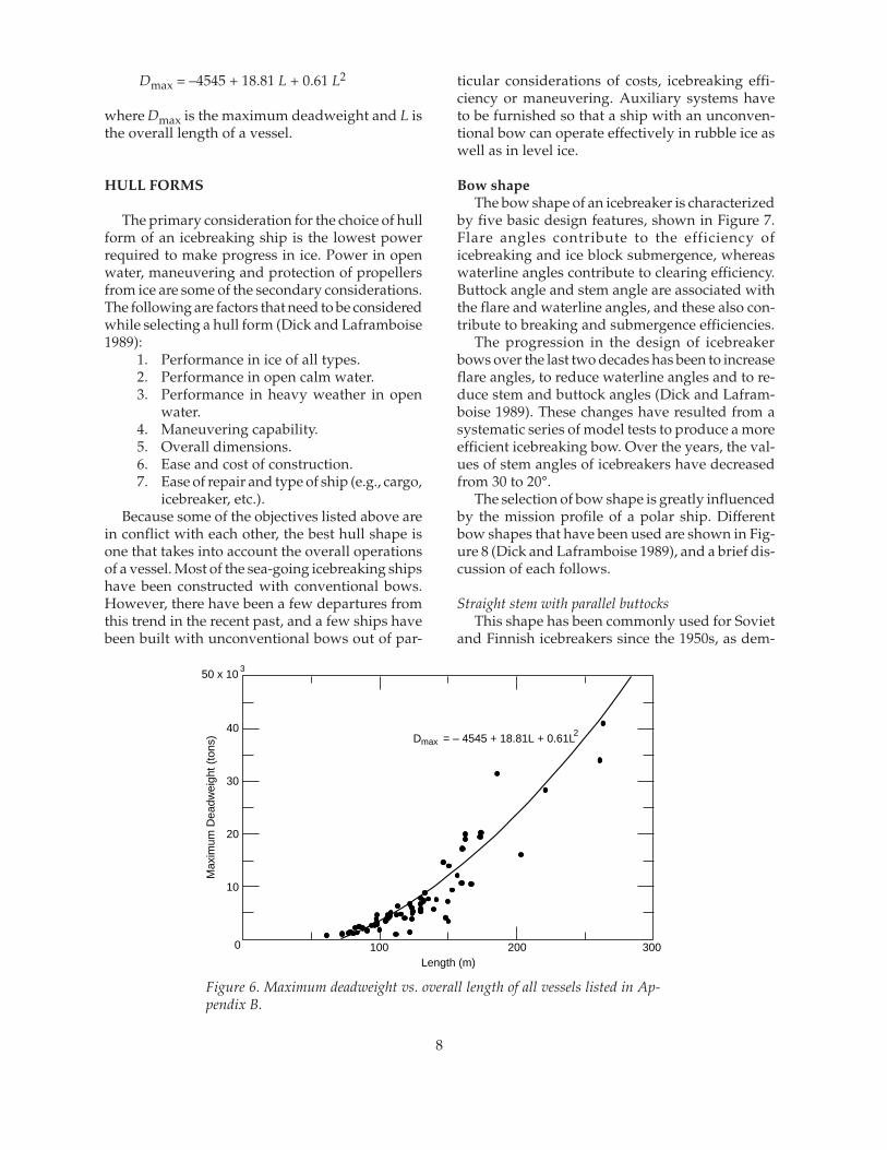
Dmax = –4545 + 18.81 L + 0.61 L2
where Dmax is the maximum deadweight and L isthe overall length of a vessel.
HULL FORMS
The primary consideration for the choice of hullform of an icebreaking ship is the lowest powerrequired to make progress in ice. Power in openwater, maneuvering and protection of propellersfrom ice are some of the secondary considerations.The following are factors that need to be consideredwhile selecting a hull form (Dick and Laframboise1989):
1. Performance in ice of all types.2. Performance in open calm water.3. Performance in heavy weather in open
water.4. Maneuvering capability.5. Overall dimensions.6. Ease and cost of construction.7. Ease of repair and type of ship (e.g., cargo,
icebreaker, etc.).Because some of the objectives listed above are
in conflict with each other, the best hull shape isone that takes into account the overall operationsof a vessel. Most of the sea-going icebreaking shipshave been constructed with conventional bows.However, there have been a few departures fromthis trend in the recent past, and a few ships havebeen built with unconventional bows out of par-
ticular considerations of costs, icebreaking effi-ciency or maneuvering. Auxiliary systems haveto be furnished so that a ship with an unconven-tional bow can operate effectively in rubble ice aswell as in level ice.
Bow shapeThe bow shape of an icebreaker is characterized
by five basic design features, shown in Figure 7.Flare angles contribute to the efficiency oficebreaking and ice block submergence, whereaswaterline angles contribute to clearing efficiency.Buttock angle and stem angle are associated withthe flare and waterline angles, and these also con-tribute to breaking and submergence efficiencies.
The progression in the design of icebreakerbows over the last two decades has been to increaseflare angles, to reduce waterline angles and to re-duce stem and buttock angles (Dick and Lafram-boise 1989). These changes have resulted from asystematic series of model tests to produce a moreefficient icebreaking bow. Over the years, the val-ues of stem angles of icebreakers have decreasedfrom 30 to 20°.
The selection of bow shape is greatly influencedby the mission profile of a polar ship. Differentbow shapes that have been used are shown in Fig-ure 8 (Dick and Laframboise 1989), and a brief dis-cussion of each follows.
Straight stem with parallel buttocksThis shape has been commonly used for Soviet
and Finnish icebreakers since the 1950s, as dem-
Figure 6. Maximum deadweight vs. overall length of all vessels listed in Ap-pendix B.
40
30
20
10
0 100 200 300Length (m)
Max
imum
Dea
dwei
ght (
tons
) D = – 4545 + 18.81L + 0.61L2max
50 x 10 3
8

Spoon bow with reamersThe spoon-shaped bow has been more efficient
because this shape allows a constant frame flareangle throughout the bow length. As mentionedearlier, this shape was used in the past, but its usewas discontinued because of its high resistance inheavily snow-covered ice, and its tendency to pushbroken ice in front of the ship. With the introduc-tion of bubbler systems or water wash systems,these problems have been overcome.
A modification of this shape was reintroducedon the Canadian icebreakers Canmar Kigoriak, builtin 1979, and Robert Lemeur, built in 1981. The ex-tended beam at the shoulder (reamers) with theabrupt change in shape eliminates midbody resis-tance by cutting a wider channel in ice, but it causesextra resistance in open water. Recently, this shapewas also used in the European icebreakers Oden,Kapitan Nikolayev, Finnica and Nordica. The hullform of the Finnish multipurpose icebreakersFinnica and Nordica is shown in Figure 9, whichalso shows the icebreaking stern and the bi-direc-tional reamers on the sides.
Flatof Side
ButtockAngle
StemAngle
H
Lf
FlareAngle B
WaterlineAngle
Figure 7. Main features of bow forms (after Dick and Laframboise 1989).
Straight Stemwith Parallel Buttocks
ConcaveStem(White Bow)
Semi-spoon Bowwith Chines
Flat Family
High Frame Flare Angles(Melville Bow)
Spoon Bowwith Reamers Thyssen-Waas Bow
Figure 8. Different shapes of icebreaking bows (after Dick and Laframboise 1989).
onstrated by the Moskva-class icebreakers in the1960s, and the Urho-class Baltic icebreakers in the1970s.
Concave stem (White bow)Although the concave stem had been used in
earlier icebreakers, R. White developed this par-ticular shape in 1969 for efficient icebreaking andice clearing. This bow shape was used in the U.S.icebreakers Polar Star and Polar Sea, built in themid-1970s, in the Canadian icebreaking cargo shipArctic, built in the late 1970s, and in the CanadianR-class icebreakers, built between 1978 and 1984.Because of the concave stem, this bow shape hashigher frame flare angles close to the stem.
High flare angles (Melville bow)This shape was developed to reduce the
icebreaking component of ice resistance. Recently,the Canadian icebreaking cargo ship Arctic wasmodified to this type of bow, and its performanceincreased from 1 to 4 m/s (2 to 8 knots) in 1-m-thick ice.
9

Semi-spoon bow with chinesThis shape is similar to the spoon bow shape,
except that the extended beam (reamers) are re-placed by shoulder chines. This shape has beenused on vessels working in the Beaufort Sea, andit has improved icebreaking performance. But ithas had some detrimental effect on the open-wa-ter resistance.
Flat familyThese shapes are similar to the spoon bow and
semi-spoon bow shapes, except that flat plateshave been used to reduce the construction costs.This shape was developed as a compromise be-tween icebreaking capabilities and constructioncosts. This type of bow has been used on the Ca-nadian vessels Arctic Nanabush, built in 1984, andArctic Ivik, built in 1985, both being used for icemanagement in the Beaufort Sea.
Thyssen-Waas bowThis type of bow shape is a significant depar-
ture from a conventional icebreaking bow. The bowfirst breaks the ice by shearing at the maximumbeam of the ship, and then breaks the ice in bend-ing across the front of the bow. This shape is char-acterized by flat waterlines at the extreme forwardend, extended beam, a low stem angle with an iceclearing forefoot, and high flare angles below thewaterline. The ice clearing capability is so goodthat the channel behind the ship is about 85% freeof ice. As mentioned earlier, the vessels that havebeen fitted with this type of bow are the MaxWaldeck (1980), the Mudyug (1986) and the KapitanSorokin (1991).
Of the seven bow shapes listed above, the firstthree can be called “conventional” or “traditional,”because these shapes retain the smooth hull, whichoffers the least resistance in open water. The otherfour shapes are “unconventional” or “nontradi-tional,” in that these shapes are a distinct depar-
ture from the smooth hull shapes. Each shape hassome benefits and some drawbacks. Therefore, theselection of a bow shape should be based on a fullunderstanding of the operational requirements ofa ship.
Midbody shapeThe midbody shape of a polar ship is character-
ized by three parameters: flare angle, parallel sidesand longitudinal taper (Dick and Laframboise1989). The objective of midbody flare is to decreasethe resistance caused by it while passing throughthe channel broken by the bow. Some of the ice-breaking cargo ships have a long, parallel midbody.Some of the icebreakers have forward shouldersto break a wider channel to eliminate any ice resis-tance from a parallel midbody. Similarly, a mid-body with longitudinal taper eliminates ice resis-tance aft of the forward shoulders. This shape hasbeen used on barges pushed by small tugs thatoperate in sheltered water. The drawbacks of lon-gitudinal taper in the midbody are higher con-struction costs and an increased probability of get-ting stuck in pressured ice. A longitudinally ta-pered midbody is not used on icebreakers oricebreaking cargo ships.
Stern shapeAll icebreakers must move astern in ice. Some
icebreakers may move back only in the previouslybroken channel or in broken ice. But there are thoseicebreakers providing a support role that mustbreak ice while moving astern. Depending uponthe mission profile, these ships may have an icebreaking–deflecting stern shape, as shown in Fig-ure 9. The main concern while moving astern isthe ingestion of ice blocks into the propellers. De-spite many innovative stern designs and shroudedpropellers, there is still considerable interaction be-tween ice and propellers (Dick and Laframboise1989).
Figure 9. Hull form of the Finnish multipurpose icebreakers Finnica and Nordica (afterLohi et al. 1994).
10

Figure 11, giving the results of the tests con-ducted in freshly broken ice in their own channel,shows that the performance of Kapitan Nikolayevis better than that of the other two ships. For testsconducted in broken ice in old channels, KapitanNikolayev performs better than Kapitan Dranitsyn.In old channels full of broken ice, Kapitan Sorokinhad a tendency to push broken ice ahead of itselfwhen it was not able to reach a speed of 3–4 knots(1.5–2 m/s). Three rounded knives in the bow ofKapitan Sorokin work efficiently to break level ice,but they also obstruct the flow of broken ice un-derneath the bow. At times, the buildup of an icepile can bring the ship to a standstill, and force iteither to ram through the pile or to seek a newpath. While operating in drifting broken ice atspeeds up to 3–4 knots, Kapitan Sorokin showedtendencies to push ice. The performance of KapitanNokilayev improved in drifting ice fields.
Both ships with the Thyssen-Waas and conicalbows must reduce speeds in severe seas becauseof considerable wave slamming in a head sea, re-sulting in longer travel times.
Ierusalimsky and Tsoy (1994) have comparedthe cost savings as a result of conversion of bowshapes from conventional to the two types of un-conventional shapes. According to them, KapitanNikolayev, with the conical bow, had reduced op-erational costs and increased profitability, whereassimilar measures for Kapitan Sorokin, with theThyssen-Waas bow, were less favorable than thosefor the ship with the original bow. It should, how-
Figure 10. Icebreaking capabilities of three sister shipswith different bow shapes in terms of speeds in level ice ofdifferent thicknesses at a power level of 16.2 MW (afterIerusalimsky and Tsoy 1994).
Icebreaker performance withdifferent hull forms
Ierusalimsky and Tsoy (1994) presented the re-sults of full-scale tests conducted on three Russiansister ships of the Kapitan Sorokin series with differ-ent hull forms: Kapitan Sorokin, converted to aThyssen-Waas bow in 1991, Kapitan Nikolayev, con-verted to a conical bow (similar to the spoon-shaped bow) in 1990, and Kapitan Dranitsyn, stillwith the original, wedge-shaped bow. The data onthe performance of these ships were obtained over3 years, enabling a determination of any cost sav-ing resulting from the conversion to bows of dif-ferent shapes.
For breaking a level ice sheet in forward mo-tion, Figure 10 plots ship performance in terms ofthe continuous speed of these three ships in equiv-alent ice thicknesses. The plots in Figure 10 showthat Kapitan Sorokin with the Thyssen-Waas bowhas the best icebreaking capability among the threein level ice, closely followed by the KapitanNikolayev with the conical bow. The performanceof these two ships is much better than that ofKapitan Dranitsyn with its original bow. Whilebreaking a channel in fast ice, Kapitan Sorokin leftup to 40% of the ice in the channel behind it,whereas the other ships left 80–90% of the channelfilled with ice. A similar test for backward motionin level ice revealed their performance in reverseorder as that for forward motion.
Figure 11. Ship speed vs. equivalent ice thickness duringtests in broken ice with three sister ships having differentbow shapes. The ships were tested in their own channels (af-ter Ierusalimsky and Tsoy 1994).
8
6
4
2
00.8 1.2 1.6 2.0 2.4
Equivalent Ice Thickness (m)
Spe
ed (
knot
s)
2
1 3
1. With Original Bow (1978)2. With Thyssen-Waas Bow (1991)3. With Conical Bow (1990)
4
3
2
1
0
Spe
ed (
m/s
)
20
16
12
8
4
0 0.4 0.8 1.2 1.6 2.0 2.4Equivalent Ice Thickness (m)
Spe
ed (
knot
s)
1
2
3
1. With Conical Bow (1990)2.With Thyssen-Waas Bow (1991)3. With Original Bow (1978)
10
8
6
4
2
0
Spe
ed (
m/s
)
11

ever, be noted that Kapitan Nikolayev is fitted withstainless steel compound plate in the ice belt area,which may be effective in reducing the chances ofgetting stuck in ice.
STRUCTURAL DESIGN OFPOLAR SHIPS
Structural design involves the selection of ma-terial and sizes of plates and frames for maintain-ing the structural integrity of a polar ship underloads from waves and ice during its normal op-eration (Dick et al. 1987). As a result of researchand experience, much has been learned about thenature of ice loads and the mechanics of ice fail-ure. Full-scale measurements of ice loads on manyships have yielded an empirical description of iceforces and pressures that is used in design. Themagnitude of ice loads, the existence of significantdamage and the emergence of affordable nonlin-ear finite element analysis packages have togetherled to the wide use and acceptance of plastic de-sign (plastic design allows some deformation ofthe structure under extreme ice loads).
Classification ofpolar ships
All commercial vessels, including most ice-breakers, but excluding government-owned ves-sels, are classified according to the rules developedby six classification societies: Lloyds Register (LR),Det norske Veritas (DnV), American Bureau ofShipping (ABS), Bureau Veritas (BV), Germanis-cher Lloyd (GL), and Russian Register of Shipping(RS). Besides the rules of the classification societ-ies, there are three national sets of rules to controlnavigation in ice-covered waters: Finnish–Swed-ish, Russian and Canadian. The classification of avessel is used for insurance and to comply withthe international regulations, such as the Safety ofLife at Sea (SOLAS) and prevention of pollution.Government-owned vessels are also surveyed forcompliance with recognized national and interna-tional standards.
The classification societies are responsible forapproving the design and supervising the con-struction of individual vessels to ensure confor-mity with the standards set by international con-ventions and by the classification of that vessel.The vessels are subjected to annual and specialsurveys throughout their lives (Toomey 1994).
The ice classification of a vessel depends on itscapability to resist damage while navigating in ice
under normal handling conditions. Unfortunately,there are so many classifications by the differentsocieties that it is difficult to establish equivalencyamong them (Santos-Pedro 1994, Toomey 1994). Alimited equivalency among the ice classificationsof the various societies is given in the Appendix Aof a companion report by Mulherin (1994). At pre-sent, an effort is underway to standardize iceclasses as international navigation through Arcticroutes, such as the Northern Sea Route and theNorthwest Passage, becomes more attractive forshipping products between the North Atlantic andthe North Pacific (Santos-Pedro 1994). While com-paring the ice-strengthening requirements accord-ing to the Russian Register Rules and CanadianArctic Shipping Pollution Prevention Regulations(CASPPR), Karavanov and Glebko (1994) havepresented an extensive comparison of the ice loads,section modulus and shear area of frames, andthickness of shell plating. The new CASPPR (1989)regulations call for smaller scantlings and thinnershell plates than those required by Russian Rulesbecause CASPPR allows a certain amount of plas-tic deformation of the structure under extreme iceloads.
Ice loads and pressuresCompression of ice at low strain rates results in
creep deformation with or without micro-crack-ing. The constitutive relations between stress andstrain for creep deformation at low strain rates arewell known. At higher strain rates (>10–3 s–1), theice fails in a brittle manner, resulting in instabili-ties caused by macro-cracking. The failure mecha-nism for brittle failure has not been fully under-stood. Failure loads or pressures also depend onthe state of stress, e.g., uniaxial vs. multiaxial. Atpresent, the dependence of compressive failure ofice under multiaxial loading at different strain ratesis being studied by researchers all over the world(e.g., Frederking 1977, Richter-Menge et al. 1986,Smith and Schulson 1994, etc.).
There have been attempts made to relate theforces exerted on a ship or a structure by crushingof ice to the uniaxial compressive strength of ice,but these attempts to obtain empirical relationshipsthrough the use of many coefficients have not beenfruitful. Although much has been known about theforces from flexural failure and compressive fail-ure of ice at low strain rates, the understanding ofbrittle failure is still incomplete at high rates ofloading and in a multiaxial state of stress. Resultsof small-scale indentation experiments on fresh-water ice indicate that brittle failure is activated at
12

tures. The fracture toughness of steel depends onthe operating temperature and on the rate of load-ing. In Figure 13, the plane strain fracture tough-ness of two types of steel has been plotted withrespect to temperature for three rates of loading.
Steel fractures in a brittle manner, without anywarning of impending failure, when the stressesare of sufficient magnitude to propagate a crackfrom a flaw or small crack in the material. The cri-terion for crack propagation in linear elastic frac-ture mechanics is that an existing crack will growwhen the stress intensity factor at the crack tip isgreater than the fracture toughness of the mate-rial. For nonlinear material behavior, the causesfor brittle fracture have now been established, andthe relationships among the cause of fracture, thetoughness of the material, the flaw size and shape,the loading rate of the structure, and the tempera-ture are understood. From this understanding,materials and welding techniques have been de-veloped to increase the reliability of ship structures.It is the consensus of many operators that the steelused in the present generation of polar ships ismostly adequate (Dick et al. 1987).
There are currently two procedures for specify-ing the type of steel to be used in different parts ofa ship: “design by rule” and “design by analysis.”Design-by-rule procedures require the designer toconsider service temperature and to select steelgrades that have adequate notch toughness. De-sign-by-analysis procedures require the designerto consider the magnitude and the rate of loadingthat may be applied during the life of a compo-nent, and to design that component with adequatereliability according to its importance. The design-by-analysis approach places a large responsibilityon the designer, but it may provide a more reliableand economical design than that by the design-by-rule approach.
The midbody region of a ship will experiencevibrations excited by shocks at the bow, but thevibratory stresses have much longer rise time thanshock-induced stresses, resulting in small chancesof initiating a fracture. However, the static stressesfrom vibrations may be high enough to cause frac-ture in the primary structure of a ship. Ships haveexperienced brittle fracture in the midbody region,and because damage in this area is potentially morecatastrophic than damage to the bow, materials andwelding techniques should prevent both crack ini-tiation and propagation. Because small cracks anddefects in a material are inevitable, the materialselected must have crack arrest properties to stopcrack propagation.
Figure 12. Measured effective pressure vs. contact area(after Masterson and Frederking 1993).
140
120
100
80
60
40
20
Temperature (°F)– 200 – 160 – 120 – 80 – 40 0 40 80 120 160
0
Temperature (°C)– 120 – 80 0 40 80– 40
Impact
Grade 'EH' SteelGrade 'A'
LongitudinalRequirementsTransverseRequirements
Pla
ne S
trai
n F
ract
ure
Tou
ghne
ss (
)M
Pa
m
Impact
Intermediate
Stat
ic
Static
Inte
rmed
iate
Figure 13. Plane strain fracture toughness vs. tempera-ture for two grades of steel (“A” and “EH”) (after Dicket al. 1987).
high rates of indentation, resulting in nonsimul-taneous contact between the ice and the indentor.
Design values are taken from empirical relationsobtained from full-scale measurements of ice pres-sure. The data on effective pressures obtained fromfull-scale measurements during ice–ship and ice–structure interactions (Masterson and Frederking1993) are plotted with respect to contact area inFigure 12, and these data provide empirical val-ues for effective pressure to be used in design.
MaterialsConsiderable effort has been devoted by classi-
fication societies and regulatory authorities to theselection of steel grades suitable for use in the struc-ture of ships that are exposed to very low tempera-
p = 8.1A– 0.572
3 m Pond InletM.V. ArcticKigoriakHans Is. ('83)Hobson's Choice ('89)Molikpaq (May '89)Flat Jack
Mean
0.1 1.0 10 100 300
Area (m )2
Pre
ssur
e (M
Pa)
0.1
1.0
10
100
10002
13

WeldingAfter selection of steel, welding is the next most
important component in the reliability of the struc-ture of ships (Dick et al. 1987). Welds in ships mustwithstand the corrosive effects of seawater, stressescaused by cargo, icebreaking operations and wave-induced motions. The biggest variable in weldingtechnology is the skill of the welder, especiallywhen working in confined spaces. To determinethe reliability of a structure, the designer of a shipmust take into consideration the flaws in the ma-terial as well as in the welds. The importance ofquality control in welding can be assessed fromthe statistics that 95% of all defects in a structureoriginate from defects within the welded zone.
The fracture toughness of a weld depends onthe method of weld deposition, including the rate,the number of passes, heat input and electrode size.The variations in weld toughness may be largerthan those of the parent materials. Caution shouldbe exercised not to degrade the toughness proper-ties of a weld by using large electrodes and fastrates of deposition in the interests of cost saving.Research on reducing the accelerated corrosion ofwelds is under way in different parts of the world.
PlatingThe plating contributes the largest component
to the structural weight of most ships and, togetherwith the frames and the stringers, it forms the stiff-ened panels that resist the loads on a ship (Dick etal. 1987). While the weight of a ship can be reducedby reducing the plate thickness and by increasingthe framing, this increases the cost of fabrication.
When a rectangular plate supported by frameson four sides is loaded by uniform pressure thatacts perpendicular to its surface, the deflectionsand the stresses in the plate can be calculated bythe small deflection theory of plate bending, as isusually done for structural analysis. This theoryignores the membrane stresses that develop be-cause of large deflections and yielding of the ma-terial. As a result of ignoring the membrane ac-tion, the load carrying capacity estimated fromsmall deflection theory is small compared to thoseobtained from large-deflection theories and experi-ments.
Figure 14 shows plots of load vs. deflection ob-tained from experimental results and two plasticanalyses—one that considers elastic flexure fol-lowed by formation of three plastic hinges with-out any membrane action, and the other that con-siders only ideal plastic membrane action. Theloads in the plots have been made nondimensional
with respect to the collapse load predicted by theformation of three hinges without membrane ac-tion, and the deflection is made nondimensionalwith respect to the plate thickness. Figure 14 showsthat the curve depicting the experimental load-car-rying capacity of a plate is initially close to thatpredicted by elastic flexure theory for small deflec-tions, and then it approaches that predicted by theplastic membrane action theory for large deflec-tions. This suggests that thick plates form plastichinges before the membrane action is activated(Ratzlaff and Kennedy 1986).
FramingThe frames support the shell plates and resist
the loads on the shell by bending and shear defor-mation. Inspection of ice-damaged vessels has re-vealed that failure takes place consistently in thesupporting frames rather than the hull plating(Dick et al. 1987, DesRochers et al. 1994). Frameshave several components: the shell plate that actsas a flange, a web, an internal flange (optional),end brackets (optional), tripping brackets (op-tional) and cutouts (optional).
Figure 14. Pressure vs. deflection, showing domains ofdifferent behaviors from small to large deflection (afterRatzlaff and Kennedy 1986). Along the vertical axis, theapplied pressure P is made nondimensional by Pc, the pres-sure at which collapse (point C) is assumed to take place byformation of three hinges without membrane action. Alongthe horizontal axis, the maximum deflection W is made non-dimensional by the plate thickness t. The curve labeled Erepresents elastic flexure with an elastic membrane up to thecomplete formation of an edge hinge. The curve labeled Frepresents elastic flexure without membrane action, followedby the formation of the first hinge and then three hinges. Thecurve labeled N represents ideal membrane action.
8
6
4
2
0 2 4W/t
P/Pc
AC
Experimental ResultsN
F
E
14

The proposed CASPPR allow a certain amountof plastic deformation of the structure under ex-treme ice loads, and they provide factors to accountfor the post-yield buckling of stiffened structures.DesRochers et al. (1994) compared the stability offlat bars with that of angle sections in a stiffenedstructure. When a structure is designed for buck-ling according to linear analysis, flat bars areavoided because angle sections have large mo-ments of inertia to resist bending. However,DesRochers et al. (1994) found that the use of flatbar sections increased the stability of the compos-ite structure beyond the yield point of the mate-rial, whereas the structural stability decreased withthe use of angle sections as yielding progressedthrough the frame. The structure of the Canadianicebreaking cargo ship Arctic has been redesignedaccording to CASPPR to carry full ice loads with-out failure.
The Swedish icebreaker Oden is the first ice-breaker designed according to the technology be-hind the proposed CASPPR, making it possible touse a large frame spacing of 850 mm instead of thenormal 400 mm (Johansson et al. 1994). This hasresulted in considerable cost savings in construc-tion. After the voyage of Oden to the North Pole,inspection of the structural damage revealed someindents in the shell plating between frame stations30 and 76 on both sides, and some deformation inthe side and bottom frames (flange, web andbracket), but this damage was not serious. Thedamaged frames were reinforced, but the indentsin the steel plates were left as they were (Backman1994).
PROPULSION SYSTEM
The major components of the propulsion sys-tem of an icebreaking vessel, or any ship, are thepropellers, shafts, transmission systems and primemovers. The number of propellers varies betweenone and three. Developments in propulsion sys-tems that have taken place during the last four tofive decades are reflected in those of existing ice-breakers and icebreaking cargo ships, and thesebecome apparent in the plot of shaft power vs. theyear of construction (Fig. 15). Some of the specialfeatures of propulsion systems, such as control-lable-pitch propellers and mechanical transmis-sions, nozzles and various electrical transmissions,have been highlighted in Figure 15.
The dc–dc electrical transmission has been com-monly used since its introduction on the Swedish
icebreaker Ymer in 1933. Although this system isstill being used on many icebreakers, new me-chanical and electrical transmissions have been in-troduced on newer icebreakers and icebreakingcargo ships. Since 1966, the number of ships withcontrollable-pitch propellers and mechanical trans-missions is steadily increasing. The Russian LASHvessel Sevmorput, delivered in 1986, placed all ofits propulsion power on one shaft using a control-lable-pitch propeller and mechanical transmission,thus doubling the power transmitted per shaftfrom 16.65 to 29.42 MW (Fig. 15b).
One of the main reasons to use direct mechani-cal transmission is to cut down the losses in trans-mission. Since 1978, propeller nozzles have beenfitted to icebreakers to increase thrust and to pre-vent propeller damage by reducing ice ingestion.Nozzles have been installed on most of the Beau-fort Sea ice management–supply vessels, whereasPolar Sea and Polar Star have operated in ice with-out nozzles since 1976. Recently, azimuth-mount-ed propulsion units have been installed on theFinnish icebreakers Finnica and Nordica and it is
Figure 15. Shaft power vs. year of construction foricebreaking ships: (a) electrical transmission system, and(b) mechanical transmission system (after Dick andLaframboise 1989).
Electrical Transmission DC-DC AC-DC AC-AC
0
0
1940 1950 1960 1970 1980 1990
5
10
15
20
25
30
35
Year of Construction
Pow
er P
er S
haft
(MW
)
b
5
10
15
20
25
30
35
Pow
er P
er S
haft
(MW
)
a
Mechanical Transmission CPP CPP in Nozzle
43
136
315
2
23
19
2
4
15

likely that this system will be used infuture ships, because it offers goodmaneuverability in broken and intactice.
The selection of a suitable propul-sion system is based on the intendedfunctions of an icebreaking vessel.The requirements of a propulsion sys-tem are:
1. Reliability of full power on de-mand to navigate safely in theArctic.
2. Flexibility of operating effi-ciently and economically inopen water as well as in heavyice at a range of power levels.
3. Maneuverability to allow rap-id change of load, speed andpower.
4. High power-to-weight ratio todeliver the required power, with machinesas compact and light as possible.
While many combinations of prime movers,transmission systems and propellers may be pro-posed for a given ship, very few particular sys-tems would fit a given mission profile (Dick et al.1987). Ships requiring a large range of power canbe fitted with multiple engines or combined-sys-tem installations, which permit the numbers ofengines to be run according to the power require-ments of various ice conditions, to achieve the bestcombination of fuel efficiency and performance.In the following sections, a brief discussion is givenof each of the main components of a propulsionsystem.
PropellersBoth fixed-pitch and controllable-pitch propel-
lers have been installed on polar ships. Fixed-pitchpropellers have been used for many years, andthese are still being installed on most icebreakingships. However, controllable-pitch propellers havebeen used on polar ships with increasing frequencysince 1966 (Dick and Laframboise 1989). A plot ofshaft power versus propeller diameter is shownin Figure 16, where fixed-pitch and controllable-pitch propellers have been identified. The azimuththruster units installed on the Finnish icebreakersFinnica and Nordica have fixed-pitch propellers ina nozzle.
The selection of propeller type depends on thepropulsion system used. Nonreversing transmis-sion systems, such as diesel–geared or gas turbine–
60
40
20
0 82 6 10
Sha
ft P
ower
(M
W)
Propeller Diameter (m)4
USSRLASHPolar
StarSA-15
IcebreakingDredge
Fixed PitchControllable Pitch
Figure 16. Shaft power vs. propeller diameter for icebreaking ships (af-ter Dick and Laframboise 1989).
geared, may use controllable-pitch propellers toobtain astern thrust and to ease over-torquerequirements. Reversing systems, such as any ofthe electrical systems, may used fixed-pitch pro-pellers because over-torque does not affect an elec-trical system.
The design requirements of a propeller dependon the mission profile of a vessel. The aspects in-fluencing the design of a propeller are (Dick et al.1987):
1. Loads and strength requirements.2. Selection of material.3. Effects of nozzles.There are two types of interactions between ice
and propellers: ice milling and ice impact. Ice mill-ing takes place when an ice block is large or istrapped between the hull and the propeller. Dur-ing an instance of milling, ice is either crushed orsheared by the blades, and the loads can be dam-agingly high. Ice impact is caused by small-sizeice pieces that are accelerated through a propelleror thrown out radially and pushed around the edgeof the propeller disk. The loads from ice impactare relatively moderate, but it happens more fre-quently.
For propellers in a nozzle, the chances of icemilling are small, and the magnitude of the loadsgenerated are also small in comparison to thosefor open propellers. The factors that influence theice loading on a propeller have been identified, butthe ability to determine the ice milling–impactloads is not well developed because of the com-plex interaction between ice and propellers. The
16

design of an ice-strengthened propeller must meetthe dimensions and the strength requirements ofthe classification societies.
The material used for the propeller blades ofpolar ships must have high stress and impact re-sistance qualities. Stainless steel and bronze arecommonly used for ice-strengthened propellerblades. Because stainless steel has a higher erosionresistance and higher ultimate and yield strengthsthan does bronze, stainless steel propellers have aslender and efficient blade profile. Most of the ex-isting bronze controllable-pitch propellers are op-erating in nozzles, whereas most stainless steelcontrollable-pitch propellers fitted to icebreakersare open propellers. For example, bronze has beenselected for the propellers of recent Canadian ice-breakers, and the open propellers of the U.S. ice-breakers Polar Star and Polar Sea are made of stain-less steel.
Propeller nozzles are used to increase the thrustover a range of ship speed, and to protect the pro-peller from ice. Thus, the nozzles have an indirectinfluence on the design of a propeller by reducingthe load levels and thereby reducing the strengthrequirements. Ships equipped with nozzles, e.g.,Kigoriak and Arctic, have operated successfully inice with very few problems. Some of the shallow-draft vessels, however, have occasionally experi-enced clogging of their nozzles in rubbled orridged ice. Nozzles have been installed on the azi-muth-mounted propellers of Finnica and Nordica,and these are being considered for future high-powered ships.
ShaftingFor large icebreaking ships, the diameters of
propeller shafts are large because of high powerand high torque requirements. The range of diam-eters of the shafts installed in existing icebreakersis from 380 mm in Polar Stern to 980 mm in theRussian SA15 cargo ships. The basis for designingshaft diameter is that the propeller blade shouldfail before the shafting. The method to calculatethe shaft diameter depends on the modulus of thepropeller section and on the ratio of the ultimatestrength of the propeller blade material to the yieldstrength of the shaft material. The requirements ofhydrodynamic torque and ice-induced torque arespecified by the classification societies. Shafts aregenerally made of forged carbon steel, althoughin some cases low alloy steel forgings are also used.There is considerable saving in weight when high-strength steel is used.
One of the major problems found with largevessels is the misalignment of the shaft bearings.The sources of the misalignment problem are (Dicket al. 1987):
1. Deflections in the hull. 2. Eccentric thrust on the propellers, which
causes bending moments in the shaft. 3. Insufficient axial and radial bearing flexibility. 4. Changes in the height of bearings, gear case
or the engine because of thermal expansion.Dick et al. (1987) have discussed other elements
of the shaft line components, such as couplings,seals and bearings.
Mechanical transmissioncomponents
The operating speed of steam reciprocating en-gines and slow-speed diesel engines is low enoughthat the power can be transmitted directly througha shaft between the engine and a propeller. This isthe most efficient form of transmitting power to apropeller, because the only losses incurred are atthe bearings. However, most prime movers, suchas medium-speed diesel and steam and gas tur-bines, have an output speed that is too high toobtain the best propeller efficiency. A speed-reduc-ing transmission must be used to deliver power tothe propellers at the optimum speed.
As shown in Figure 15b, many icebreakers andicebreaking cargo vessels have been fitted withmechanical transmission of power since 1966. Mostof these vessels are driven by one or more medium-speed diesel engines and a set of single-reductiongears, except the Russian LASH, which is drivenby a steam turbine. A clutch or fluid coupling isused between an engine and a gear system. In afew icebreakers, flywheels have also been used tosmooth out the transient, ice-induced torque.
The gearboxes that are installed on polar shipsare within the experience of the manufacturers. Thelargest gearboxes installed on any icebreaker arethose on the U.S. icebreakers Polar Sea and PolarStar, which are powered by combined gas turbineand diesel-electric systems. The Russian SA15cargo ships have been fitted with large gearboxeswith twin inputs, each delivering 7.5 MW, and con-nected through fluid couplings to limit overloadtorque.
Electrical transmission systemsFour types of electrical transmission systems are
available for polar ships. These systems are listedaccording to their chronological order of develop-
17

ment: dc–dc, ac–ac, ac–dc, and ac–FFC–ac. An acsystem is preferred because of its light weight andhigher efficiency. The problems of commutationin dc systems are not present in ac systems.
The advantages of an electrical transmissionover a mechanical one are that the characteristicof the drive can be exactly matched with the mis-sion profile of a ship, and that the total power forthe ship can be divided among a number of en-gines. There is flexibility in the placement of gen-erators in a ship. An electrical system also isolatesthe prime mover from the overload torque causedby ice loads on the propellers. The disadvantagesof an electrical transmission system are the highercosts, greater weight and larger space require-ments.
With medium-speed diesel engines as primemovers, the dc–dc system is most commonly usedin icebreakers. The maximum speed of a dc gen-erator must be less than 100 rpm owing to the lim-ited capacity of the commutator brushes to trans-mit current. The advantages of a dc system are itssimplicity, ease of control, good torque character-istics (especially at low speed) and lower cost thanother electrical systems. In comparison to mechani-cal transmission systems, the disadvantages of thissystem are its higher cost, greater weight and vol-ume, lower transmission efficiency (about 85%)and a relatively high requirement for manpower.
The ac–dc system combines the advantages ofac generators with the precise speed control of dcmotors. The generated power, in three-phasealternating current, is converted with low lossesto direct current by the use of thyristors, whichwere developed in the 1960s.
The ac–ac propulsion system is based on syn-chronous motors. The speed is changed by chang-ing the speed of the prime mover. It is the simplestand least expensive. This system, while perhapsbeing the economical choice for open water ships,is not suitable for icebreaking ships. The genera-tor and the motor may fall out of synchronizationwhen the propellers are subjected to large ice loads.Other disadvantages of this system are the lowtorque at start up and the excitation of resonantvibrations.
The ac–ac system with Full Frequency Control(FFC), or a cyclo-converter, is the most suitable butalso the most expensive ac–ac system. It has beenused in the Finnish icebreakers Otso, Finnica andNordica, in the Russian Taymyr-class icebreakersand in Canadian light icebreakers. By employingcyclo-converters, the motors can be precisely andsteplessly controlled by a highly reliable control
setup. Its advantages are the availability of fulltorque over the entire range of speed, no loss ofsynchronization, operation of the prime mover atits optimum speed, and the availability of powerfor auxiliary systems from the main generators.Its main disadvantages are the high capital cost,high volume and weight, and relatively poor over-all transmission efficiency of 90–92% (estimated),although the transmission efficiency of ac–FFC–ac systems is higher than that for ac–dc and dc–dcsystems.
Azimuth propulsion driveAzimuth propulsion drives have been installed
on different types of vessels, such as icebreakers,cargo ships, ferries, cruise ships, etc. One of theLunni series tankers, Uikku, was converted in 1993to accommodate 11.4-MW azimuth propulsiondrives (one of the world’s most powerful units),replacing the original medium-speed diesel, gear-ing, shafting and controllable-pitch propellers. In-stallation of these units on the multipurpose ice-breakers Fennica and Nordica has produced excel-lent icebreaking and maneuvering capabilities.With their advanced hulls (designed to give excel-lent seakeeping in open waters [Fig. 9]), these ves-sels can make continuous progress through 1.8-m-thick ice. Their icebreaking capabilities are alsovery good when they are moving astern. The azi-muth thruster units allow these ships to turn onthe spot in ice conditions. Lohi et al. (1994) givethe results of full-scale ice tests with Fennica dur-ing her trials in the Baltic.
There are two commercial azimuth propulsionsystems available—Aquamaster and Azipod. In anAzipod unit, an ac electrical motor is located in-side the pod, whereas the motor is located abovethe azimuth thruster units in Aquamaster drives.The motor, controlled by a frequency converter,directly drives a fixed-pitch propeller, which is ei-ther open or placed in a nozzle. These drives azi-muthally move 360° and supply full power in alldirections.
Figure 17 shows the difference between conven-tional diesel–mechanical and azimuth propulsionsystems on an arctic tanker. The azimuth systemhas the following advantages:
1. Gives excellent dynamic performance andmaneuvering characteristics.
2. Eliminates the need for long shaft lines, trans-verse stern thrusters, controllable-pitch propellersand reduction gears.
3. Allows new ways for designing machineryand cargo spaces.
18

60
50
40
30
20
10
0
01940 1950 1960 1970 1980 1990
5
10
15
20
25
30
35
Year of Construction
Pow
er P
er S
haft
(MW
)T
otal
Pow
er (
MW
)
Medium Speed DieselSlow Speed DieselSteam TurbineGas Turbine
a
b
Figure 18. Prime movers installed on icebreaking ships:(a) total power vs. year of construction, and (b) powerper shaft vs. year of construction (after Dick andLaframboise 1989).
Figure 17. Differences between diesel-mechanical and azimuth installations(after Kværner Masa-Yards and ABB,no date).
Diesel-mechanical Propulsion System
Azimuth Propulsion System
4. Reduces noise and vibrations.5. Provides operational flexibility, resulting in
lower fuel consumption, reduced maintenancecosts, fewer exhaust emissions and adequate re-dundancy with less installed power.
In late 1990, the propulsion system of the Finn-ish waterway service vessel Seili was convertedfrom diesel-mechanical propulsion to azimuth(Azipod) propulsion. The performance of this ves-sel was tested in 65-cm-thick, level ice in the Gulfof Bothnia. Laukia (1993) reported that, besidesgood maneuverability and icebreaking capabilityin level ice and first-year pressure ridges, the ves-sel broke ice better when moving astern than whilemoving ahead. There are unconfirmed reportsthat new vessels with two types of hulls at eachend are on the drawing boards of shipyards: asmooth bow for moving forward in open-water,and an icebreaking stern for moving asternthrough first-year ice in sheltered areas.
Prime moversThe characteristics of an ideal prime mover for
an icebreaking ship are reliability, flexibility, ma-
neuverability, robustness and over-torque capabil-ity (Dick and Laframboise 1989). These character-istics have been discussed earlier for the propul-sion system. The prime movers used currently inpolar ships do not have all these characteristics,but in combination with a suitable transmission,the overall propulsion system can approach theabove-mentioned ideal characteristics.
Figure 18 shows two plots of total installedpower and power per shaft versus the year of con-struction. In Figure 18 different types of primemovers have been identified. Each type is brieflydiscussed in the following.
Gas turbinesOnly two icebreakers, the USCG Polar Star and
Polar Sea, are fitted with gas turbines. Each shiphas three aero-engine derivative gas turbines, eachdriving a controllable-pitch propeller through agearbox. These turbines are used only for heavyicebreaking, and a medium-speed diesel-electricpropulsion system is used for cruising and lighticebreaking. The Canadian icebreaker NormanMcLeod Rogers was initially fitted with two indus-
19

trial turbines, but they were replaced with me-dium-speed diesel engines because of high fuelconsumption.
Turbines are unidirectional engines, and theastern operations must be provided by the trans-mission, usually through an electrical system, areversing gear or a controllable-pitch propeller. Theadvantages of gas turbines over other prime mov-ers are their high power-to-weight ratio and theircompactness. Their main disadvantages are thehigh fuel consumption and maintenance re-quirements.
Steam turbinesOnly the Russian nuclear-fueled icebreakers and
icebreaking cargo ships are fitted with modernsteam turbines. The Canadian icebreaker Louis S.St. Laurent was fitted with a steam-turbine–elec-tric system, but a diesel-electric system was in-stalled during the ship’s major reconstruction pro-gram, completed in 1993. The efficiency of a steamturbine is about 20%, compared to 50% for mod-ern marine diesel engines (Dick et al. 1987). Simi-lar to gas turbines, steam turbines are unidirec-tional engines, and astern operations must behandled by the transmission. Turbines can oper-ate at any power level, but the fuel efficiency ispoor at reduced power levels.
Medium-speed diesel enginesMedium-speed diesel engines have most com-
monly been used as prime movers for the propul-sion of polar ships because of their compactness,light weight, fuel efficiency and good reliability(Dick and Laframboise 1989). Their disadvantagefor use as prime movers is their lack of significantover-torque capacity. However, this shortcomingis overcome by using an electrical transmission,which damps out the high torque transients andstops them from being transmitted to the engine.A few icebreakers are fitted with these enginesdriving controllable-pitch propellers throughgears. Some of the direct drive systems consist offluid couplings to prevent engine stall under themost severe propeller overloads.
In the past 15 years, medium-speed diesel en-gines have undergone developments that haveallowed them to have better fuel economy, burnheavier grades of fuel, increase routine mainte-nance intervals and increase the power per cylin-der. Some of the largest engines of this type cangenerate about 22 MW at 400 rpm in 18 cylindersarranged in a vee form (Dick et al. 1987). The en-gines operate in one direction, and separate pro-
visions, in the form of controllable-pitch propel-lers or reversing gears, are used for astern op-erations. Typical specific fuel consumption of theengines is between 170 and 200 g/kWh, and theconsumption of lubricating oil is between 1.5 and3 g/kWh. Most medium-speed diesel engines foricebreakers use turbochargers to improve their fuelefficiency in open water. Diesel engines are basi-cally constant torque machines in the 50–100%range of speed. At a given load, torque may ex-ceed the rated capacity by about 10%. The flexibil-ity of diesel engines is acceptable because they canoperate between 25 and 35% of their rated speed,depending upon the characteristics of a particularengine. It is expected that medium-speed dieselengines will continue to be the preferred primemovers for polar ships of all sizes in the near fu-ture (Dick et al. 1987).
Slow-speed diesel enginesThe Russian LASH ship Alexey Kosygin is the
only polar ship fitted with two slow-speed dieselengines, each delivering 13.4 MW to directly drivefixed-pitch propellers (Dick et al. 1987). This typeof engine was specifically developed for ship pro-pulsion. They operate on the two-stroke cycle, arereversible, and are directly coupled to propellers,mostly of the fixed-pitch type. The range of theirrotational speed is between 60 and 225 rpm. Therange of cylinder bore diameter is from 250 to 900mm. The maximum power per cylinder is about3.7 MW. This type of engine is large and heavy,and it can only be fitted to vessels that can providea large engine room and carry the extra weight:bulk cargo ships, oil tankers and container ships.Ferries, Ro/Ro ships and barge carriers have lim-ited head room and are generally fitted with me-dium-speed diesel engines. These engines are notsuitable for polar ships because of their poor ma-neuverability and flexibility.
Developments in the last 15 years include theuse of constant pressure turbocharger technologyand the adoption of extra-long strokes. This hasenabled slower propeller speeds without the useof gears, resulting in higher propulsion efficiencyin large bulk carriers and oil tankers. The specificfuel consumption of these engines is below 160 g/kWh for large economical engines, and about 175g/kWh for small engines.
Combined prime moversThe reason for combining two different prime
movers in a ship is to improve the overall fueleconomy. This is done by either recovering the
20

waste heat and converting it to mechanical work,or by operating each prime mover according toload demands to obtain better fuel economy. Thefirst option has not been used in icebreakers so far.
The USCG icebreakers Polar Sea and Polar Starare the only polar vessels fitted with two types ofprime movers. In these ships, there are three gasturbines (total 45 MW or 60,000 shp) and three die-sel-electric propulsion systems (total 13.4 MW or18,000 shp) for each of the three controllable-pitchpropellers. Each shaft can be turned either by thediesel-electric or the gas turbine power plant. Ei-ther one or two 2.24-MW (3000-shp) diesel-elec-tric drive units, or a single 15-MW (20,000-shp) gasturbine, can be used to drive each shaft. For ex-ample, diesel engines could supply power to thewing shafts, while a gas turbine could turn thecenter shaft. Gas turbines are used for heavy ice-breaking, whereas the diesels are used for cruis-ing and light icebreaking. This is a good exampleof combining two different systems to meet widelydiffering load demands for the sake of fueleconomy.
AUXILIARY SYSTEMS
There have been other developments to improvethe performance of polar ships besides those inpropulsion systems and hull shapes, such as theuse of low-friction coatings on the hull, air-bub-blers to lubricate the ice/ship interface, air-bub-bler–water-injection systems, and the water-del-uge (or wash) system to pump a large volume ofwater on the ice ahead of the vessel. These im-provements have also contributed to increase theicebreaking capability of polar ships beyond thelimit for which they were designed. A brief ac-count of each auxiliary system follows.
Low-friction hull coatingDepending on the age of a vessel, the coefficient
of friction between ice and unpainted hull platingcan be in the range of 0.2 to 0.3, which is high incomparison to the friction coefficient in the rangeof 0.05 to 0.17 between ice and a low-friction coat-ing. As discussed later, the factor to account forthe friction of old steel in the expression for iceresistance of an icebreaker is twice that for Inerta-coated steel plates (Keinonen et al. 1991).
Prior to the 1970s, there was no suitable coatingavailable that could withstand interaction with ice.Only anti-fouling paint was applied to the hulls tominimize biological growth on the hull surface,
and this would wear off during first few days oficebreaking. In the early 1970s, the importance ofhull–ice friction on the ice resistance was demon-strated through full-scale and laboratory tests. Ameasure of the force attributable to static frictionacting on a hull can be obtained by gradually in-creasing the level of power to initiate forwardmotion of a ship that was stopped in ice and thenmeasuring the steady-state velocity at that samepower level. For ships having uncoated hulls, thispower level corresponds to a 3-knot (1.5-m/s)speed of advance, whereas for a ship with low-friction coating, the initiating power levels areequivalent to a speed of 0.5 knots (0.26 m/s) (Voelker1990). The power required for an icebreaker with alow-friction coating to become unstuck is muchlower than that for ships without any coating.
Mäkinen et al. (1994) have given an historicalaccount of the development of low-friction coat-ings in Finland, where the first effective hull coat-ings were developed by Wärtsilä Shipyard (nowKværner Masa-Yards). Liukkonen (1992) devel-oped a theoretical understanding of hull–ice fric-tion and found a functional relationship betweenthe coefficient of friction and the normal force. Thisfunctional relationship was verified by full-scalemeasurements of normal and frictional forces withthe help of instrumented panels installed in thebow and the sides of icebreakers.
Mäkinen et al. (1994) have listed the require-ments of a good low-friction coating. A few of theseare reasonable cost, high bond strength with andgood corrosion protection for the base material,and resistance to all of the following: wear, highnormal pressure, low temperatures and changesin temperature. Tests were conducted on many dif-ferent coatings; Inerta 160 and stainless steel wereselected for full-scale testing and further devel-opment. Another coating by the name of Zebronwas also found to be suitable, but its use has de-creased with time, perhaps because of lower resis-tance to wear.
Inerta 160 has been applied to hundreds of shipscurrently in service (Mäkinen et al. 1994). It is ap-plied with a two-component spray gun, which hasheating equipment to keep the temperature of thepaint between 40 to 50°C. Two problems associ-ated with the application of Inerta 160 were corro-sion of cast iron propellers and corrosion of hullsurfaces. These problems were corrected by usingstainless steel propellers and cathodic corrosionprotection.
An important property of a coating is to with-stand the deformation of the base material. In the
21

Figure 19. Outboard profile and topside deck plan of the Swedishicebreaker Oden.
Heeling systemIn earlier times, the crews of cargo
ships that were stuck in ice found that lift-ing a heavy weight by a crane and swing-ing it sideways helped to free the ship.This experience led the designers of ice-breakers to install heeling tanks on eachside of a ship and to provide for pump-ing large amounts of water back and forthbetween the tanks. The continuous roll-ing motion of a ship facilitates its prog-ress in ice with less power.
Now most operators consider the heel-ing system important for improvedicebreaking and maneuvering. Almost allBaltic icebreakers have heeling tanks. TheSwedish icebreaker Oden was fitted witha fast heeling system that allows full heel-ing in 15 seconds (Backman 1994). Thishas enabled Oden to make continuous
progress in heavy ridges. Oden is also fitted withturning reamers located above the ice surface oneach side just aft of the bow (Fig. 19), and whenthe ship is heeled over, one reamer comes in con-tact with ice to help the ship to turn sharply intothe heel (Johansson et al. 1994). Thus, a heelingsystem in combination with the turning reamershas improved the maneuverability of Oden by de-creasing the turning radius. With improvedmaneuverability, polar ships are often able to makeprogress in thicker ice than they have been de-signed for, by finding a path of least resistancethrough the weaknesses in an ice cover. This isdemonstrated by the successful voyage of Oden in1991 with the German icebreaker Polarstern to theNorth Pole.
Air-bubbler systemAn air-bubbler system releases large volumes
of air through nozzles into the water below the icein the bow and midbody portions of a ship. Whenthe air rises to the surface, it brings water with itbetween the ice and the hull, thus reducing fric-tion between them.
This system was first introduced on the Finnishicebreaking ferry Finncarrier in 1969 (Johansson etal. 1994). It has since been installed on vessels withconventional bows, such as the Lunni class oficebreaking tankers, the Canadian icebreakingcargo ship Arctic, and the Russian SA15’s. The re-sults of full-scale trials indicate that a bubblersystem may help in reducing friction only in thelow-speed range (less than 2 m/s or 4 knots). There
case of Inerta 160, the wear-off starts at the crackscaused by the deformation of the shell plating atthe edges of the ship’s frames. The wear-off isintensified in heavily loaded areas, such as the icebelt in the ship’s forebody, and during operationsin heavy ice and especially in the presence of soilor sand mixed in ice. To correct this deficiency inInerta 160, stainless-steel-coated surfaces, thoughexpensive, were developed because of their highwear resistance and low-friction properties. Ca-thodic protection systems were developed to re-duce the corrosion risks before compound steelswith stainless steel claddings were installed in theice belt regions on two Otso-class icebreakers fortesting. Later, stainless steel compound plates wereinstalled on the Russian icebreaker KapitanNikolayev and the Finnish icebreakers Finnica andNordica with very favorable results.
The cost of applying Inerta 160 and installingstainless steel compound plates is, respectively,about 2 and 40 times the cost of applying conven-tional paint (Mäkinen et al. 1994). However, theextra cost of applying Inerta 160 may be offset bylonger periods (4–5 years vs. 1 year) between re-applications of the coating, while compound steeldoes not require any repair or reapplication. Therehave been no corrosion problems with compoundplate; however, the cathodic protection systemsmust be permanently activated, even during thesummer. Investigations are currently underway touse copper-nickel compound plates as an alterna-tive to stainless steel compound plates (Mäkinenet al. 1994).
22

is no measurable benefit of an air-bubbler systemon ships with unconventional bows. Captains ofBay-class Great Lakes icebreakers report that airbubblers are very useful for docking or leaving thedocks under ice conditions.
To assess the effectiveness of hull lubrication byan air-bubbler system, the ratio of shaft powersaved at a given speed in level ice to the power re-quired to operate the system is computed. If thisratio is more than one, there is a net power savingin operating the system. According to the data com-piled by Keinonen et al. (1991), this ratio for theair-bubbler system of hull lubrication is generallyless than, or in some cases barely greater than, one.The reason for such low efficiency is that lu-brication is not provided around the bow water-line, where it would be most effective.
Air-bubbler–water injection systemThis system, installed on the German icebreaker
Polarstern, injects air into the water being pumpedto nozzles at the sides of the ship below the ice.Air–water jets have also been installed below thewater on the Canadian icebreaker Ikaluk and thenewly converted Russian icebreaker Mudyug. Theratio of power saved to the power expended isabout one (Keinonen et al. 1991).
Water-deluge systemRecent developments, such as the water-deluge
system and low-friction epoxy paint, have allowedthe use of unconventional bows on sea-going ves-sels (Johansson et al. 1994). A water-deluge sys-tem throws several tons of water every second ontop of the ice ahead of the bow. This not only re-duces friction between the ice and the hull but alsosubmerges the broken ice pieces to help them movedown under the hull. This was first installed onthe Canadian icebreaker Canmar Kigoriak, whichwas fitted with a blunt spoon-shaped bow, to solvethe ice pushing problem experienced with uncon-ventional bows in the late nineteenth century. Onetime, when the water-deluge system was frozensolid, the Kigoriak could not make good progressthrough a broken ice cover because of the ice-push-ing problem. With the water-deluge system operat-ing perfectly a few days later, she was able to makegood progress in this same broken ice field(Johansson et al. 1994).
According to the data compiled by Keinonen etal. (1991), the power saved as a result of operatinga water-deluge system is much greater than thepower expended. These data were collected for the
Canmar Kigoriak during icebreaking with a barehull and also with an epoxy-coated hull.
On the Canadian icebreaking supply vessel Rob-ert Lemeur, this system has been effective in reduc-ing the resistance by 20–30% over the entire speedrange (Dick and Laframboise 1989). On the Swed-ish icebreaker Oden, the water-deluge system hasbeen upgraded to act as a bow thruster by direct-ing the flow to one side of the ship. With a controlsystem and a modified nozzle design, it is possibleto obtain a side force of 0.1 MN at the forward tipof the ship.
POWER AND PERFORMANCE
As expected, installed power increases with shipsize as represented by ship beam. The power-ver-sus-beam plot of the data on existing polar ships(Fig. 20) shows a trend of increasing power as afunction of beam. Except for a few data points,there appears to be a well-defined relationshipbetween power and beam.
Using information on the performance of ex-isting polar ships in ice, Dick and Laframboise(1989) plotted the bollard pull/beam vs. the icethickness an icebreaker is capable of breaking at aspeed of about 1 m/s or 2 knots (Fig. 21). For com-parison, the data are normalized on performancefor a speed of 2 knots. There appears to be a well-defined minimum performance. For a particularbollard pull/beam, the range of ice thickness abovea minimum performance value represents an im-provement in icebreaking capability of the hullshape. Figure 21 shows that the most recent shipshave more efficient hull forms.
40
60
20
0 10 20 30
Pow
er (
MW
)
Beam (m)
SIBIRPolarStar
TerryFox
Supply Boats
Figure 20. Power vs. beam for icebreakers (after Dickand Laframboise 1989).
23

Ice Thickness (m)0.5 1.0 1.5 2.0 2.50
Bol
lard
Pul
l/Bea
m (
tonn
es/m
)
25
20
15
10
5
PolarStar
Arktika
TaymyrTerry FoxShiraseUrho
New ArcticRobert Lemeur
NewMudyugMax Waldeck
Kigoriak
PolarStern
SA 15
MinimumPerformance
Bol
lard
Pul
l/Bea
m (
kN/m
)
–250
–200
–150
–100
–50
–0
Pt. BarrowWrangell Is.
St. Lawrence Is.
Nome
Cape Lisburne
Pt. Hope
USA
Nunivak Is.
St. Matthew Is.
St. Paul Is.
St. George Is.
Ice Edge
Dutch Harbor
Aleutian Islands
170°180° 160°
55°
50°
60°
65°
70°
Russia
6.2-7.2 m/s@ 23.9 MW
3.1-4.6 m/s@ 9.0 MW
6.2 m/s@ 11.2 MW
4.6 m/s@ 6.0 MW
5.1 m/s@ 14.9 MW
7.2 m/s@ 16.4 MW
3.6 m/s@ 9.0 MW
6.2-7.2 m/s@ 9.0 MW
7.2-8.2 m/s@ 9.0 MW
Figure 22. Speeds and power levels of U.S. icebreaker Polar Sea during her transit from 23March to 4 April 1983 (after Voelker 1991).
Figure 21. Icebreaking performance: bollard pull/beam vs. ice thickness. Bollard pull is measured orcalculated; data are adjusted for a speed of 2 knots (af-ter Dick and Laframboise 1989).
24

Table 2. Estimates of daily fuel consumption for a Polar-class ice-breaker.
Fuel consumption rateShip status (gallons/day) (tons/day)*
Stationary—systems providing onlynormal hotel services 4,000 12
Open water transit (three propulsion diesel) 14,000 42Icebreaking (six propulsion diesel) 25,000 75Icebreaking (diesel on wing shafts,
gas turbine on center shaft) 35,000 105Icebreaking (three gas turbines) 60,000 180
* Relation used for conversion: 1000 gallons/day ≈ 3 tons/day.
into the Alaskan Chukchi Sea. Figure 23 identifiessections of the route where ramming of the ice wasrequired to make headway. The number of ramsand the average shaft power used are also givenin Figure 23.
According to the brochures of the MurmanskShipping Company, the rates of fuel consumptionof three classes of ships (Norilsk, Mikhail Strekalov-skiy and Dimitriy Donskoy) are listed in Table 3.
Performance predictionKeinonen et al. (1991) compared the perfor-
mance of 18 major icebreakers of different sizesand types to establish methods of expressing andestimating their performance in terms of ship de-sign features and parameters. The data were ob-tained from full-scale trials of icebreakers in dif-ferent geographical areas as well as in different ice
Table 3. Fuel consumption rates of a few Russian ships according to the informationgiven in the brochures of the Murmansk Shipping Company.
Daily consumption rate (tons/day)Storage In port
Type of capacity Cargo No cargoShip fuel or oil (tons) Underway operation operation
SA15’s Diesel oil 783 2.0 2.0 1.0Noril’sk High viscosityClass fuel 3743 76.0 7.0 3.0
Lubricating oil 185 0.6 0.1 0.1
Mikhail Diesel oil 329 5.0 2.5 2.5Strekalovskiy High viscosityClass fuel 1348 43.1 7.3 7.3
Lubricating oil 52 0.3 — —
Dimitriy Diesel oil 329 5.0 2.5 2.5Donskoy High viscosityClass fuel 1348 43.1 7.3 7.3
Lubricating oil 52 0.3 — —
Fuel consumption ratesThe fuel consumption rates of medium-speed
and slow-speed diesel engines have been men-tioned earlier. These rates may have been obtainedfor open water conditions. Data on the actual fuelconsumption of icebreakers working in ice are veryscarce.
Voelker (1990) has summarized the mean fuelconsumption rates of 16 Polar-class ship deploy-ments to the Alaskan Arctic (Table 2). The rate offuel consumed depends on the ship’s activity andthe power plant being used. The Polar Sea and Po-lar Star can each generate up to 13.4 MW (18,000shp) using diesel-electric propulsion systems. Al-ternatively, they can generate up to 45 MW (60,000shp) by engaging their gas-turbine power plants.In Figure 22, Voelker’s route map shows the sus-tained speeds for various power outputs during amidwinter expedition through the Bering Sea and
25

Figure 23. Number of ramming operations during the transit of U.S. icebreaker Polar Seafrom 23 March to 4 April 1983 (after Voelker 1991).
Pt. BarrowWrangell Is.
St. Lawrence Is.
Nome
Cape Lisburne
Pt. Hope
USA
Nunivak Is.
St. Matthew Is.
St. Paul Is.
St. George Is.
Ice Edge
Dutch Harbor
Aleutian Islands
170°180° 160°
55°
50°
60°
65°
70°
Russia
10 Rams@ 23.9 MW 33 Rams
@ 34.3 MW 7 Rams
@44.8 MW
220 Rams @ 34.3 MW 14 Rams @ 44.8 MW
14 Rams @ 23.9 MW 147 Rams@ 34.3 MW
15 Rams@ 9.0 MW 53 Rams@ 23.9 MW
information, readers are referred to their paper andto the reports prepared for that study. A summaryof their performance predictors is given below.
Resistance in level iceFor chined ships, an expression for ice resistance
at a speed of 1 m/s is given as
R1 = 0.08+0.0177 CS CH B0.7 L0.2 T0.1 H1.25
{1 – 0.0083 (t + 30)} {0.63 + 0.00074 σf}
{1 + 0.0018 (90 – ψ)1.4} {1 + 0.004 (ϕ – 5)1.5}
conditions. Though most of the hulls were coatedwith Inerta, a few hulls were bare steel, and onehull was fitted with a stainless-steel band at thewaterline. Performance measures included in theirstudy are level-ice hull resistance, propulsive per-formance, hull lubrication, ridge resistance, turn-ing performance and open water resistance. Ac-cording to Keinonen et al. (1991), these results werecompiled to understand the influence of key pa-rameters on the performance of icebreakers. Thekey parameters chosen for this comparison weresimple and obvious to all observers. For detailed
26

where D = turning diameter (m)LWL = length of waterline of ship (m)
x = reamer width relative to midbodylength (%).
For rounded vessels with fully effective rud-ders, and in level ice of thickness equal to 60%of the icebreaking capability at 1m/s
D/LWL = 0.022 (PMB)1.75 + 3
where PMB is the percentage of waterline lengthrepresenting a parallel midbody (%).
For rounded vessels with partially effective rud-ders, and in level ice of thickness equal to 60% ofthe icebreaking capability at 1 m/s
D/LWL = 0.14 (PMB)1.5 + 3.
Open water resistanceFor chined vessels, open water resistance is ex-
pressed in terms of Froude number
R/Disp = 1.1 Fn1.64
where R = open water resistance (kN)Disp = ship displacement (tons)
Fn = Froude number
v gL/
v = ship velocityL = ship length between perpendiculars.
For vessels of rounded shapes, open water re-sistance is expressed in terms of Froude number
R/Disp = 0.4 Fn1.68.
Propulsive performancePropulsive performance is defined as the ratio
of net thrust to the shaft power (or specific netthrust). Keinonen et al. (1991) compared the pro-pulsive performance of different icebreakers at fullpower. The data are shown in Figure 24a for dif-ferent speeds for ships having ducted propellers,whereas similar data for ships with open propel-lers are shown in Figure 24b. A comparison of thedata for the single-screw, ducted, controllable-pitchsystem of Kigoriak and Arctic with that of twin-screw, open, controllable-pitch system of Terry Foxshows that the net propulsive performance of theducted systems has an advantage of 27% over theopen system at low speeds. However, this advan-tage decreases at higher speed until both systemshave the same specific net thrusts.
where R1 = resistance in level ice at 1 m/s (MN)CS = water salinity coefficient (saline = 1,
brackish = 0.85 and fresh = 0.75)CH = hull condition factor (Inerta = 1, new
bare steel = 1.33 and old bare steel = 2)B = ship beam (m)L = waterline length of ship (m)T = draft of ship (m)H = ice thickness, taken to be ice thickness
plus half the snow depth (m)t = ice surface or air temperature (°C)
σf = flexural strength of ice (kPa)ψ = average flare angle in bow region (°)ϕ = average buttock angle in bow region
(°).
For rounded-shoulder ships, an expression (us-ing the same symbols) for the ice resistance at aspeed of 1 m/s is given as
R1 = 0.015 CS CH B0.7 L0.2 T0.1 H1.5
{1 – 0.0083 (t + 30)} {0.63 + 0.00074 σf}
{1 + 0.0018 (90 – ψ)1.6} {1 + 0.003 (ϕ – 5)1.5}.
Energy to penetrate anunconsolidated ridge
Based on the full-scale data, an expression forthe energy to penetrate an unconsolidated ridge isgiven as
ER = 0.25 AC AR CS CH {1 – 0.0083 (t + 30)}
{1 + 0.012 (90 – ψ)}
where ER = energy for ridge penetration (MJ)AC = largest cross-sectional area of vessel
(m2)AR = ridge depth × ridge profile length
(rubble only) (m2)CS = water salinity coefficient (saline = 1,
brackish = 0.85 and fresh = 0.75)CH = hull condition factor (Inerta = 1, new
bare steel = 1.33 and old bare steel = 2)t = ice surface or air temperature (°C)
ψ = average flare angle in bow region (°).
Turning circle diameterFor vertical-sided chined vessels, and in level
ice of thickness equal to 60% of the icebreakingcapability at 1 m/s
D/LWL = 38 × 0.56x
27

b. Open propellers.
Figure 24. Specific net thrust vs. speed at maximum shaft power, indicating propulsive perfor-mance (after Keinonen et al. 1991).
a delivery scheduled for mid-1998.* Its displace-ment will be 16,303 tons, and its length, beam andmaximum draft will, respectively, be 128 m, 25 mand 9.75 m. The propulsion systems will consist of22.4 MW (30,000 hp), medium-speed diesel engineswith ac–ac electrical transmission to drive twofixed-pitch propellers. Model tests indicate that itwill be able to break 1.6-m-thick, level ice continu-ously. It will have a dynamic positioning systemto support oceanographic research.
The design and model testing of a new U.S. Arc-tic Research Vessel has been completed (Kristen-sen et al. 1994), but it is not known at this timewhen this research vessel will be built. This vesselwill support science missions in the Arctic well into
FUTURE ICEBREAKERS
At present, some of the largest icebreakers, suchas the Russian Yamal, are capable of operating inmulti-year ice without any concern for possibledamage, often at speeds in the range of 15–20 knots(7.7–10.3 m/s) (Brigham 1994). The icebreakers ofthis class are strongly built, with a robust propul-sion system. Because of nuclear power, their unlim-ited endurance sets this class of ships apart fromthe rest of the icebreakers in the world. Detailedinformation about the icebreaker Yamal by R.K.Headlands of Scott Polar Institute is given in Ap-pendix A, which states that the maximum ice thick-ness Yamal can penetrate while navigating is esti-mated to be 5 m, and that Yamal has broken throughindividual ridges estimated to be 9 m thick.
The contract to build an icebreaker, named Healy,for the U.S. Coast Guard has been executed, with
* Personal communication, A.D. Summy, Captain, U.S.Coast Guard, 1994.
00
0.04
0.08
0.12
0.16
0.2
2 4
Speed (m/s)
6 8 10
Net
Thr
ust/
Pow
er (
N/W
)
KicoriakM. V. AcrticPolarsternOden
a. Propellers in nozzles.
Kigoriak
Terry FoxPolar ClassR-ClassH. LarsenA. HarveyLouis S. St. LaurentBay ClassOTSO
00
0.14
0.12
0.10
0.08
0.06
0.04
0.02
2 4
Speed (m/s)
6 8 10
Net
Thr
ust/
Pow
er (
N/W
)
28

for the Northwest Passage is slightly bigger in sizeand displacement than Yamal, but the designed in-stalled power (from diesel engines with a mechani-cal transmission to two controllable-pitch propel-lers in nozzles) is less than that of Yamal, which isequipped with three propellers driven by nuclearpower through an electrical transmission. Auxil-iary systems for the Northwest Passage icebreakerinclude water wash and heeling tanks, as well as astainless steel belt with Inerta coating elsewhere.
Figure 25 is a sketch of an “iceraker,” as pro-posed by Johansson et al. (1994). The proposediceraker has a vertical-sided, 50-m-wide hull thatalso has a submerged cantilever in front of and oneach side of the vertical, wedge-shaped bow. Atthe edge of this cantilever, air is introduced intothe water at a depth of about 15 m. Seven spursare located on top of the cantilever at a transversespacing of about 20 m. The spurs create a 120-m-wide channel of broken ice by deflecting a floating
the next century. The ship will have an overalllength of 103.6 m, waterline length of 93.9 m, maxi-mum beam of 27.1 m, depth of 12.2 m, draft of 9.1m and a displacement of 11,684 tons. The vesselwill have a flat bow with a ridge in the middle tobreak ice in bending and to clear it on the side,and a double hull to comply with the CASPPRguidelines. The propulsion system will include die-sel engines of 15 MW (20,000 hp) and two-ducted4.1-m-diameter controllable-pitch propellers.
As mentioned earlier, it is well within knownand proven technology and experience to design,build and operate an icebreaker year-round inde-pendently in the Arctic. Keinonen (1994) has setdown the performance criteria of a proposed ice-breaker for the Northwest Passage, as given inTable 4. The design parameters of the icebreakerare given in Table 5, in which the values of thoseparameters for Yamal are also given for compari-son. It can be seen that the icebreaker proposed
Table 5. Comparison of design parameters of proposed Northwest Passage icebreaker (Keinonen 1994) withthose of the Russian icebreaker Yamal.
Proposed values for aNorthwest Passage Values for the Russian
Parameter Unit icebreaker icebreaker Yamal
Displacement ton 30,000 23,460Water line length m 140 136Length of parallel mid body m 70 no dataBeam at water line m 30 28Draft m 14 11Hull design concept type four-section bow conventional, straight
wedge shaped, doubleStem/buttock angle degrees 17 17Flare/frame opening angle degrees 60 —Shaft power MW 40 56Propellers number/type 2CP in nozzles 3FPDrive system engine/transmission diesel/mechanical nuclear/steam turbine/
electricalReamers type—width m two way—2 m noneAppendages names stern pods, shilling ice horn
rudders, bottom wedgeAuxiliary systems types water wash, heeling air bubblerHull coating types Stainless and Inerta polymer coating
coating with cathodicprotection
Table 4. Performance criteria for a Northwest Passage icebreaker (after Keinonen 1994).
Performance Criteria/measure Requirements
Level ice 2 knots at continuous speed 3 mMulti-year ice Thickest broken ice on first ram 8 mBacking Thickest level ice ice broken in a continuous motion 2 mTurning Thickest ice below which turning circle is smaller than 10×Lwl 2 mExtraction Wind speed in which able to extract (also needs to be able to 15.4 m/s
extract after any ram) (30 knots)
29

hull of a ship, it has now become possible to buildicebreakers with improved bow shapes to copewith any type of ice. The developments in marinepropulsion systems were also incorporated into theicebreaking technology to obtain higher efficiency,reliability, flexibility and maneuverability. Devel-opment of auxiliary systems, such as heeling tanks,air-bubbler systems, water-deluge systems, low-friction coatings, etc., allows an icebreaker to per-form effectively in ice conditions more severe thanthose for which they were designed.
A description of the Russian nuclear-poweredicebreaker Yamal is given in Appendix A. An inven-tory of ships that are capable of navigating in atleast 0.3-m-thick ice is presented in Appendix B.
LITERATURE CITED
Backman, A. (1994) Five years operational experi-ence with the Swedish icebreaker Oden. In Proceed-ings, 5th International Conference on Ships and Ma-rine Structures in Cold Regions, March, Calgary,Alberta, Canada, p. R1–18.Brigham, L.W. (1987) Emerging polar ship tech-nology—an introduction. Marine Technology Soci-ety Journal, 21(3): 3–5.
0 20 40 60 80 100 120 140 160 180 200 (m)
Water Line
Ramming Multi-year Floes (30 m)Loose Pack (24 m)Breaking Solid Ice (18 m)
Figure 25. New “iceraking” concept, asproposed by Johansson et al. (1994).
ice sheet upward sufficiently to fracture it. The airreleased from the edge of the cantilever producesa current to take the broken ice pieces past the 60-m-wide main body of the iceraker. While movingthrough broken ice, the iceraker is submerged to adeeper level so that the spurs do not contact theice. To break a thick (8-m) multiyear ice floe, theiceraker is submerged even deeper and allowedto strike the floe to split it in a single impact.
The proposed “iceraker“ represents an innova-tion that may not become a reality for a long time.Enormous economic driving forces must bepresent to encourage building this type of vesselthat is such a great departure from existing ice-breaking ships.
SUMMARY
The current status of icebreaking technology hasbeen presented, along with a brief history. Theimprovements in bow designs to break level iceefficiently were suggested more than a hundredyears ago. However, those designs could not beimplemented in sea-going ships because of ice-pushing problems. With the help of new develop-ments to reduce friction between the ice and the
30

Brigham, L.W. (1991) Technical developments andthe future of Soviet Arctic marine transportation.In The Soviet Maritime Arctic (L. W. Brigham, Ed.).Annapolis, Maryland: Naval Institute Press.Brigham, L.W. (1992) Modern icebreaking ships.In The Shipping Revolution: The Modern MerchantShip (R. Gardiner, Ed.). London: Conway MaritimePress, p. 154–158.Brigham, L.W. (1994) Observations of the Russianicebreaker Yamal. Memorandum dated 2 Septem-ber (unpublished).Dick, R.A. and J.E. Laframboise (1989) An em-pirical review of the design and performance oficebreakers. Marine Technology, 26(2): 145–159.Dick, R.A., D.N. Baker, E.W. Thompson and H.C.Cheung (1987) Arctic Ship Technology. TransportCanada Report TP 8094E. Ottawa, Ontario:Melville Shipping Ltd.DesRochers, C.G., E.J. Crocker and I. Bayly (1994)Post yield buckling of stiffened panel structures.In Proceedings, 5th International Conference on Shipsand Marine Structures in Cold Regions, March,Calgary, Alberta, Canada, p. K1–11.Frederking, R. (1977) Plane-strain compressivestrength of columnar-grained and granular-snowice. Journal of Glaciology, 18(81): 505–516.Ierusalimsky, A.V. and L.G. Tsoy (1994) The effi-ciency of using non-traditional hull lines for ice-breakers. In Proceedings, 5th International Conferenceon Ships and Marine Structures in Cold Regions,March, Calgary, Alberta, Canada, p. S1–10.Johansson, B.M., J. Ciring, W. Jolles, E. Stalderand R.D. Rowe (1994) Revolutionary icebreakerdesign. In Proceedings, 5th International Conferenceon Ships and Marine Structures in Cold Regions,March, Calgary, Alberta, Canada, p. O1–34.Karavanov, S.B. and Y.V. Glebko (1994) New Rus-sian Arctic regulations versus CASPPR. In Proceed-ings, 5th International Conference on Ships and Ma-rine Structures in Cold Regions, March, Calgary,Alberta, Canada, p. C1–10.Keinonen, A. (1994) Icebreaker for North WestPassage, a designer’s perspective. In Proceedings,5th International Conference on Ships and MarineStructures in Cold Regions, March, Calgary, Alberta,Canada, p. W1–10.Keinonen, A., R.P. Browne, C.R. Revill and I.M.Bayly (1991) Icebreaker performance prediction.Transactions, The Society of Naval Architects and Ma-rine Engineers, 99: 221–240.Kristensen, D.H., B.L. Hutchison, A. Keinonen,and K.-H. Rupp (1994) Ice-breaking and openwater performance prediction of the new UNOLS/NSF Arctic Research Vessel. In Proceedings, 5th In-
ternational Conference on Ships and Marine Structuresin Cold Regions, March, Calgary, Alberta, Canada, p.N1–18.Kværner Masa-Yards and ABB (no date) Azimuth-ing electric propulsion drive: Azipod. Helsinki,Finland.Laukia, K. (1993) Service proves electric propul-sion design. The Motorship, February.Liukkonen, S. (1992) Theoretical approach tophysically modelling of kinetic friction betweenice and ship. In Proceedings, 11th International Con-ference on Offshore Mechanics and Arctic Engineer-ing, Calgary, Alberta, Canada, vol. IV. New York: Am-erican Society of Mechanical Engineers, p. 213–222.Lohi, P., H. Soininen and A. Keinonen (1994) MSVFennica, a novel icebreaker concept. In Proceedings,5th International Conference on Ships and MarineStructures in Cold Regions, March, Calgary, Alberta,Canada, p. M1–14.Mäkinen, E., S. Liukkonen, A. Nortala-Hoikanen,and A. Harjula (1994) Friction and hull coatingsin ice operations. In Proceedings, 5th InternationalConference on Ships and Marine Structures in ColdRegions, March, Calgary, Alberta, Canada, p. E1–22.Masterson, D.M. and R.M.W. Frederking (1993)Local contact pressures in ship/ice and structure/ice interactions. Cold Regions Science and Technol-ogy, 21: 169–185.Milano, V.R. (1987) The Thyssen/Waas ice-breaking hull form. Marine Technology Society Jour-nal, 21(3): 75–87.Mulherin, N. (1994) Northern Sea Route reconnais-sance report: History and present status of opera-tions. USA Cold Regions Research and Engineer-ing Laboratory, Report to the U.S. Army EngineerDistrict, Alaska.Mulherin, N., D.S. Sodhi and E. Smallidge (1994)Northern Sea Route and icebreaking technology:An overview of current conditions. USA Cold Re-gions Research and Engineering Laboratory, Mis-cellaneous Paper 3520.Ratzlaff, K.P. and D.J.L. Kennedy (1986) Be-haviour and ultimate strength of continuous steelplates subjected to uniform transverse loads. Ca-nadian Journal of Civil Engineering, 13: 76–85.Richter-Menge, J.A., G.F.N. Cox, N. Perron, G.Durell and H.W. Bosworth (1986) Triaxial testingof first-year sea ice. USA Cold Regions Researchand Engineering Laboratory, CRREL Report 86-16.Smith, T.R. and E.M. Schulson (1994) Brittle com-pressive failure of salt-water columnar ice underbiaxial loading. Journal of Glaciology, 40(135): 265–276.Santos-Pedro, V.M. (1994) The case for harmoni-zation of (polar) ships rules. In Proceedings, 5th In-
31

ternational Conference on Ships and Marine Structuresin Cold Regions, March, Calgary, Alberta, Canada, p.D1–8.Toomey, P.R.M. (1994) A master’s perspective onthe performance of icebreakers. In Proceedings, 5thInternational Conference on Ships and Marine Struc-tures in Cold Regions, March, Calgary, Alberta,Canada, p. V1–16.
Voelker, R.P. (1990) Arctic marine transportationprogram, 1979 to 1986, executive summary. ReportNo. MA-RD-840-90004 prepared by NKF Engineer-ing, Inc., Arctic Technology Group, Columbia,Maryland, for Maritime Administration, Office ofTechnology Assessment, Department of Transpor-tation.
32

The ship is one of three Rossiya class icebreakersleased to the Murmansk Shipping Companyby the Russian Government (her sisters areRossiya [launched in 1985] and Sovetskiy Soyuz[1990]).
The name is derived from a Nenets word meaning“End of the Earth,” also applied to the YamalPeninsula.
Her keel was laid on 25-V-1986 in St. Petersburgand she was launched on 28-X-1992
Registered number M 43048 and International CallSign UPIL.
Length overall 150 m, at waterline 136 m. Breadthoverall 30 m, at waterline 28 m. Draft 11.08 m.
Height, keel to mast head: 55 m on 12 decks (4 be-low water).
Ice knife, a 2-m-thick steel casting, is situated about22 m aft of the prow
Displacement 23,455 tonnes; capacity 20,646 grossregistered tons.
The cast steel prow is 50 cm thick at its strongestpoint.
The hull is double with water ballast betweenthem. The outer hull is 48 mm thick armor steelwhere ice is met and 25 mm elsewhere.
Eight bulkheads allow the ship to be divided intonine watertight compartments.
Ice breaking is assisted by an air bubbling system(delivering 24 m3/s from jets 9 m below thesurface), polymer coatings, specialized hulldesign and capability of rapid movement ofballast water. Ice may be broken while mov-ing ahead or astern.
An M1-2 or KA-32 helicopter is carried for observ-ing ice conditions ahead of the ship.
The ship is equipped to undertake short tow op-erations when assisting other vessels throughice.
Searchlights and other high intensity illuminationsare available for work during winter darkness.
Complement 131: 49 officers and 82 other ranks.Power is supplied by two pressurized water
nuclear reactors using enriched Uranium fuelrods.
Each reactor weighs 160 tonnes, both are containedin a closed compartment under reduced pres-sure.
Fuel consumption is approximately 200 g per dayof heavy isotopes when breaking thick ice. 500
APPENDIX A: INFORMATION ABOUT THE NUCLEAR ICEBREAKER YAMAL
(Reproduced from an unpublished description given by R.K. Headland ofScott Polar Institute, Cambridge University, UK)
kg of Uranium isotopes are contained in eachreactor when fully fueled. This allows about 4years between changes of the reactor cores.
Shielding of the reactor is by steel, high densityconcrete and water. The chain reaction can bestopped in 0.6 seconds by full insertion of thesafety rods.
Used cores are extracted and new ones installedin Murmansk, spent fuel is reprocessed, andwaste is disposed of at a nuclear waste plant.
Ambient radiation is monitored by 86 sensors dis-tributed throughout the vessel. In accommo-dation areas this is 10 to 12 µRöntgen/hr,within the reactor compartment, at 50% power,800 µRöntgen/hr.
The primary cooling fluid is water, which passesdirectly to four boilers for each reactors; steamis produced at 30 kg/cm2 (310°C).
Main propulsion system: each set of boilers drivestwo steam turbines that turn three dynamos(thus six dynamos may operate). 1 kV dc isdelivered to three double-wound motors con-nected directly to the propellers.
Electricity for other purposes is provided by fivesteam turbines turning dynamos that developa total of 10 MW.
There are three propellers; starboard and midshipsones turn clockwise, port turns counter-clock-wise. Shafts are 20 m long. Screw velocity isbetween 120 and 180 rpm.
Propellers are fixed, 5.7 m diameter and weigh 50tonnes; each has four 7-tonne blades fixed bynine bolts (16 tonne torque applied); inspec-tion wells allow them to be examined in op-eration.
Four spare blades are carried; diving and otherequipment is aboard so a blade may be re-placed at sea; each operation takes from 1 to 4days (three such changes have been necessaryon Rossiya icebreakers since 1985).
A propulsive effort of 480 tonnes can be deliveredwith 18–43 MW (25,000 shaft horsepower)from each screw (total 55.3 MW [75,000 shafthorsepower]).
Power can be controlled at a rate of 1% a second.Maximum speed is 22 knots (40 km/hr); full speed
in open water is 19.5 knots (35 km/hr); break-ing ice 2–3 m thick can be done at 3 knots (5.5km/hr) continuously.
33

Maximum ice thickness that can be penetratedwhile navigating is estimated as 5 m; indi-vidual ridges estimated at 9 m thick have beenbroken through.
Helm controls one rudder, which turns 35° eitherway, operated by four hydraulic cylinderspowered by one of two pumps. It is protectedby an ice-horn for moving astern.
Steering may also be provided by directing air jetsof the bubbling system (comparable to use ofbow-thrusters).
Auxiliary power is available from three diesel gen-erating sets: 1 MW (1×) and 250 kW (2×).
Anchors: two 7-tonne anchors with 300 m of chaineach, and four ice anchors.
Four deck cranes are aboard; the largest pair canlift 16 tonnes each.
Sea water distillation: two vacuum stills can sup-ply 5 m3 of fresh water an hour each (240 m3/day).
Differential ballast tanks are suitable fore and aft,and athwart the ship; the pumps are capableof moving 1 m3 of water a second.
Ship has 1280 compartments (cabins, storage ar-eas, machine rooms, etc.).
Sufficient provisions and supplies can be carriedto operate for 7 months.
Safety equipment includes: 1 launch, 2 fully en-closed lifeboats, and 18 inflatable life rafts.
34

APPENDIX B: AN INVENTORY OF EXISTING SHIPS THAT ARE CAPABLE OFNAVIGATING IN AT LEAST 0.3-m-THICK ICE COVER
(Inventory compiled by Leonid Tunik)
35
[The paper version of this report includes the mate-rial listed in the Table of Contents above, but is notreproduced here. Paper copies are available throughthe National Technical Information Service. See theinside cover of this report for ordering information.]
TABLE OF CONTENTS
INTRODUCTION .............................................................................................................................................. 36
REGULATORY AGENCIES...............................................................................................................................36REGULATIONS................................................................................................................................................... 37SHIPS INCLUDED.............................................................................................................................................. 37SCOPE OF DATA................................................................................................................................................. 38
NOTES TO THE PRINTED EDITION ...........................................................................................................39
NOTES TO THE ELECTRONIC EDITION ..................................................................................................40
DATABASE FILE STRUCTURE........................................................................................................................ 40LIST OF TABLES INCLUDED....................................................................................................................... 40MAIN TABLE DESCRIPTIONS...................................................................................................................... 40LOOK-UP TABLE DESCRIPTIONS.............................................................................................................. 43TABLE RELATIONSHIPS...............................................................................................................................44
ACRONYMS USED ........................................................................................................................................... 45
REGISTER NAMES......................................................................................................................................... 45BOW SHAPE.................................................................................................................................................... 45COUNTRY........................................................................................................................................................ 45SHIP TYPES..................................................................................................................................................... 46PROPULSION MACHINERY.......................................................................................................................... 46
BIBLIOGRAPHY ............................................................................................................................................... 47
INDEX OF SHIP SERIES BY ICE RANK ....................................................................................................51
INDEX OF SHIPS WITH SERIES NAME ....................................................................................................54
LIST OF SERIES AND SHIPS WITH SPECIFICATIONS ........................................................................60
LIST OF SHIP OWNERS WITH SHIP NAMES ..........................................................................................225

42
1. AGENCY USE ONLY (Leave blank) 2. REPORT DATE 3. REPORT TYPE AND DATES COVERED
4. TITLE AND SUBTITLE 5. FUNDING NUMBERS
6. AUTHORS
7. PERFORMING ORGANIZATION NAME(S) AND ADDRESS(ES) 8. PERFORMING ORGANIZATION REPORT NUMBER
9. SPONSORING/MONITORING AGENCY NAME(S) AND ADDRESS(ES) 10. SPONSORING/MONITORING AGENCY REPORT NUMBER
11. SUPPLEMENTARY NOTES
12a. DISTRIBUTION/AVAILABILITY STATEMENT 12b. DISTRIBUTION CODE
13. ABSTRACT (Maximum 200 words)
14. SUBJECT TERMS 15. NUMBER OF PAGES
16. PRICE CODE
17. SECURITY CLASSIFICATION 18. SECURITY CLASSIFICATION 19. SECURITY CLASSIFICATION 20. LIMITATION OF ABSTRACT OF REPORT OF THIS PAGE OF ABSTRACT
NSN 7540-01-280-5500 Standard Form 298 (Rev. 2-89)Prescribed by ANSI Std. Z39-18298-102
REPORT DOCUMENTATION PAGEForm ApprovedOMB No. 0704-0188
Public reporting burden for this collection of information is estimated to average 1 hour per response, including the time for reviewing instructions, searching existing data sources, gathering andmaintaining the data needed, and completing and reviewing the collection of information. Send comments regarding this burden estimate or any other aspect of this collection of information,including suggestion for reducing this burden, to Washington Headquarters Services, Directorate for Information Operations and Reports, 1215 Jefferson Davis Highway, Suite 1204, Arlington,VA 22202-4302, and to the Office of Management and Budget, Paperwork Reduction Project (0704-0188), Washington, DC 20503.
June 1995
Devinder S. Sodhi
U.S. Army Cold Regions Research and Engineering Laboratory72 Lyme Road Special Report 95-17Hanover, New Hampshire 03755-1290
U.S. Army Engineer District, AlaskaAnchorage, Alaska
Approved for public release; distribution is unlimited.
Available from NTIS, Springfield, Virginia 22161
239Auxiliary systems Icebreakers Inventory of icebreaking shipsHull forms Icebreaking history Propulsion system
UNCLASSIFIED UNCLASSIFIED UNCLASSIFIED UL
Northern Sea Route Reconnaissance Study: A Summary of IcebreakingTechnology
Since the advent of steam power, icebreakers have been built to navigate in ice-covered waters. The hull formsof early icebreakers were merely an adaptation of open water hull shapes, by sloping bow angles more to createvertical forces for breaking ice in bending. However, these bow forms were found to be unsuitable for sea-goingvessels because they push broken ice ahead of them. This experience led to construction of all sea-going vesselswith wedge-shaped bows from 1901 to 1979. With the introduction of low-friction coatings and the water-deluge system, it is now possible to operate ships with blunt bows efficiently in broken ice. New developmentsin marine propulsion technology have also been incorporated to obtain better icebreaking efficiency and per-formance. Both fixed-pitch and controllable-pitch propellers are in use. Nozzles surrounding the propellers arealso used to increase the thrust and to reduce ice–propeller interaction. Electrical and mechanical transmissionsystems have been used in icebreakers to improve the characteristics of the propulsion system. Though manytypes of prime movers are used in icebreakers, medium-speed diesel engines are the most popular because oftheir overall economy and reliability. Appendix A is a description of the Russian icebreaker Yamal, which is oneof the largest and most powerful icebreakers of the world today. Appendix B contains an inventory of existingships that are capable of navigating in at least 0.3-m-thick ice. Some of the present icebreakers are capable of

13. ABSTRACT (cont’d).
navigating almost anywhere in the ice-covered waters of the Arctic and the Antarctic, and multi-purpose icebreakershave been built to operate not only in ice during the winter but also in open water doing other tasks during thesummer. With sufficient displacement, power, navigation equipment, and auxiliary systems, future icebreakers thatcan operate independently year-round in the Arctic and the Antarctic are well within the known technology andoperational experience.
236