not and or xor nand nor - aldenham computing this topic we have covered: • nand function (not...
TRANSCRIPT
NOT
AND
OR
XOR
NAND
NOR

Expression 1: It is raining today
Expression 2: Today is my birthday
Binary representation of the above:
X Meaning
True It is raining today
False It is not raining
X Meaning
1 It is raining today
0 It is not raining
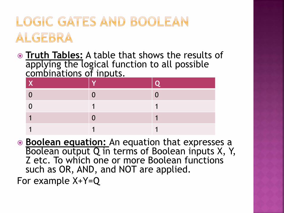
Truth Tables: A table that shows the results of applying the logical function to all possible combinations of inputs.
Boolean equation: An equation that expresses a Boolean output Q in terms of Boolean inputs X, Y, Z etc. To which one or more Boolean functions such as OR, AND, and NOT are applied.
For example X+Y=Q
X Y Q
0 0 0
0 1 1
1 0 1
1 1 1

Supply Lamp
Supply Lamp
=0
=1
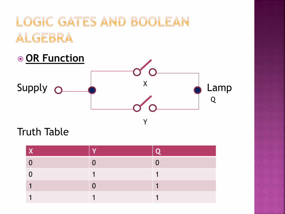
OR Function
Supply Lamp
Truth Table
X
Y
Q
X Y Q
0 0 0
0 1 1
1 0 1
1 1 1
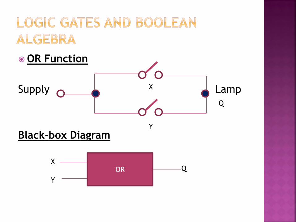
OR Function
Supply Lamp
Black-box Diagram
X
Y
Q
OR X
Y
Q

AND Function
Supply Lamp
Black-box Diagram
X Y Q
AND X
Q
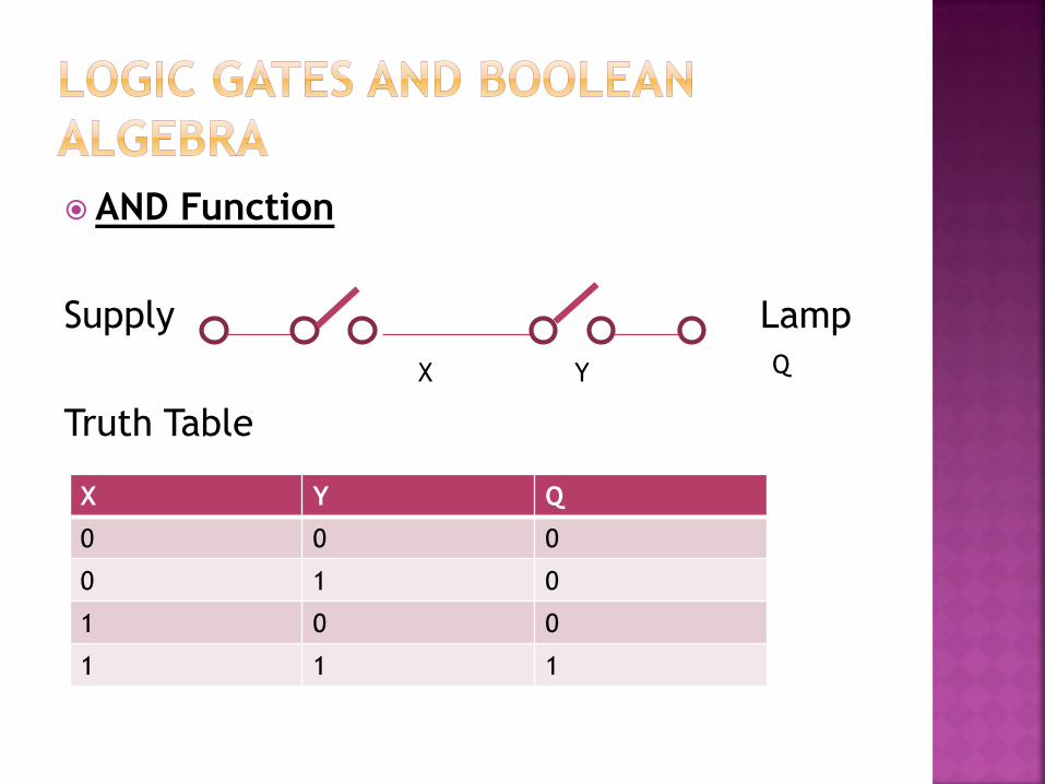
AND Function
Supply Lamp
Truth Table
X Y Q
X Y Q
0 0 0
0 1 0
1 0 0
1 1 1
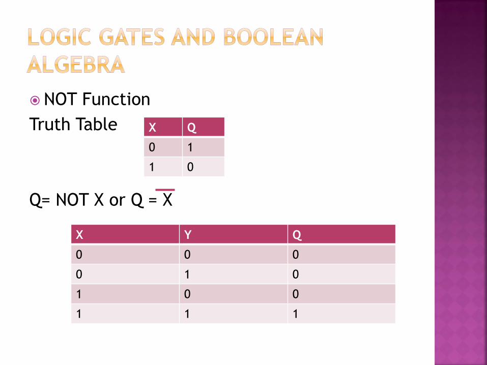
NOT Function
Truth Table
Q= NOT X or Q = X
X Q
0 1
1 0
X Y Q
0 0 0
0 1 0
1 0 0
1 1 1
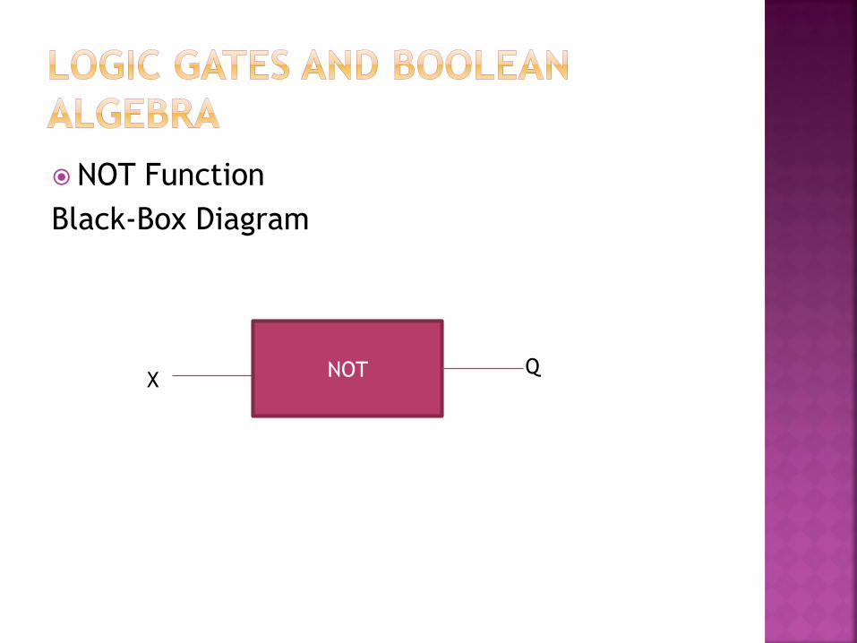
NOT Function
Black-Box Diagram
NOT
X Q

Combination of AND and OR
Supply Lamp X
Y
Z
Q
Boolean equation from the above arrangements:
Q=(X AND Y) OR (X AND Z)
Q=X.Y + X.Z
Q= x.(Y+Z)

1. Draw the truth tables for the AND, OR and NOT functions
2. What logic function is performed by the switch arrangement shown below?
3. Draw a switch arrangement for the AND function
4. Draw the switch arrangement for output Q where Q=X.Y + X.Z
X
Y
Q
Supply Lamp
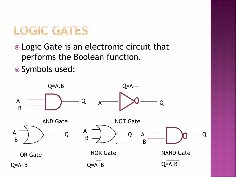
Logic Gate is an electronic circuit that
performs the Boolean function.
Symbols used:
AND Gate NOT Gate
OR Gate NOR Gate
A
B
Q A Q
A
B Q Q
A
B
Q=A.B Q=A
Q=A+B Q=A+B
Q
Q=A.B
A
B
NAND Gate

A
B
C
D
E
F
Q
Q=(A.B)+(C.D)
Q=E+F

A
B
C
D
E
F
Q
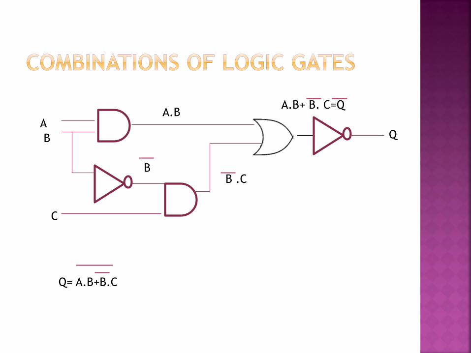
Suppose we require an output Q from three inputs A, B, C
such that
Q= 0 when A is present (1) and B is present (1)
OR
When B is not present (0) but C is present (1)
Q= A.B + B.C
A
B
C
Q
Q= A.B+B.C
A.B
B B .C
A.B+ B. C=Q
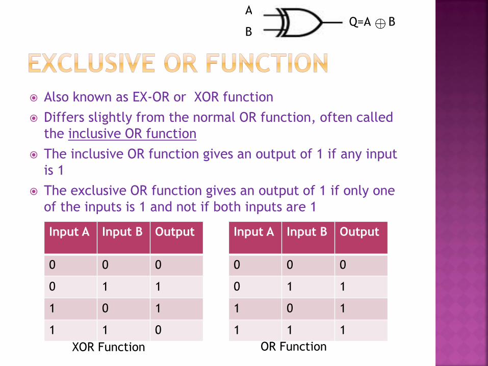
Also known as EX-OR or XOR function
Differs slightly from the normal OR function, often called
the inclusive OR function
The inclusive OR function gives an output of 1 if any input
is 1
The exclusive OR function gives an output of 1 if only one
of the inputs is 1 and not if both inputs are 1
Input A Input B Output
0 0 0
0 1 1
1 0 1
1 1 0
Input A Input B Output
0 0 0
0 1 1
1 0 1
1 1 1
XOR Function OR Function
Q=A B A
B
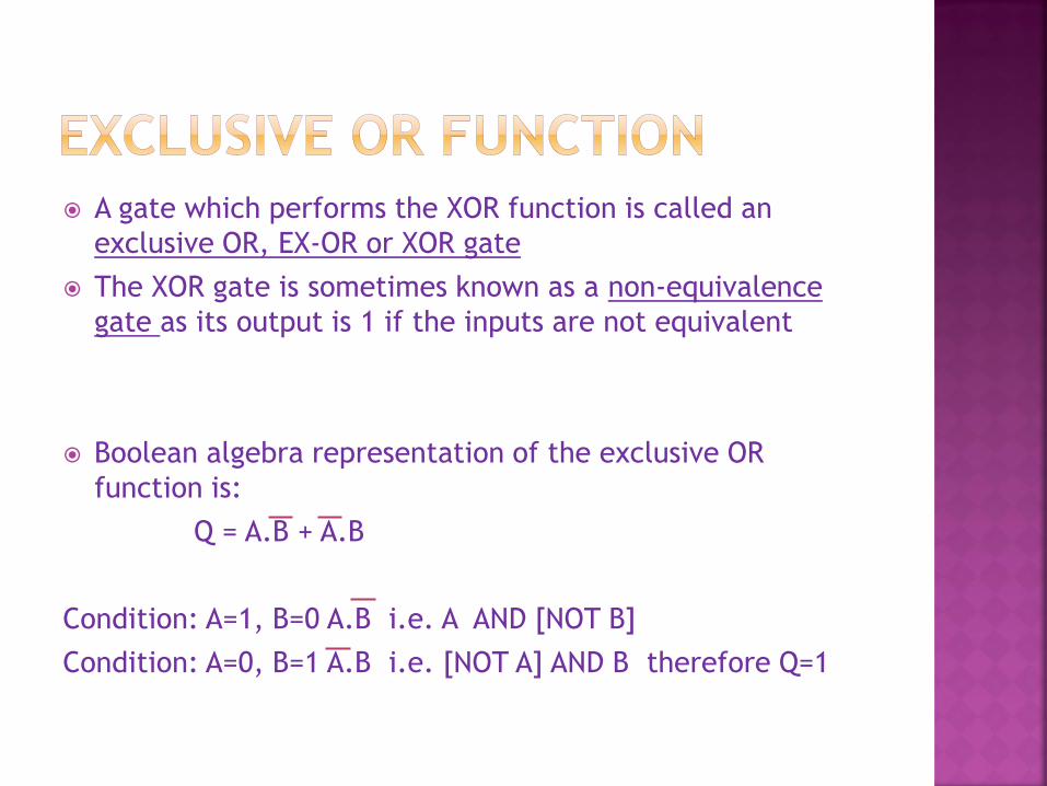
A gate which performs the XOR function is called an
exclusive OR, EX-OR or XOR gate
The XOR gate is sometimes known as a non-equivalence
gate as its output is 1 if the inputs are not equivalent
Boolean algebra representation of the exclusive OR
function is:
Q = A.B + A.B
Condition: A=1, B=0 A.B i.e. A AND [NOT B]
Condition: A=0, B=1 A.B i.e. [NOT A] AND B therefore Q=1
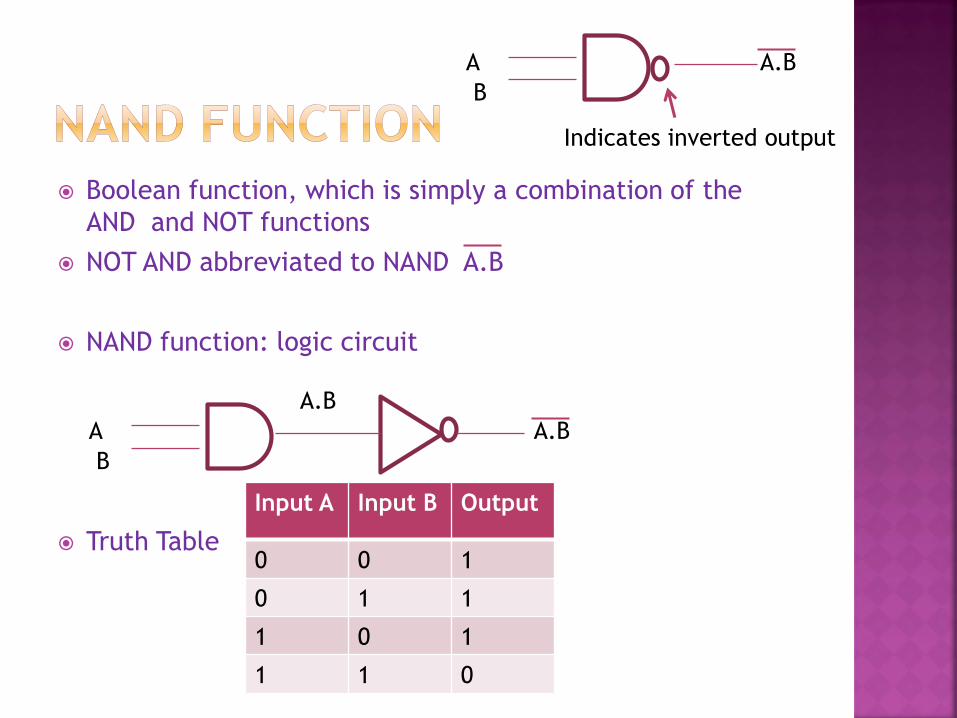
Boolean function, which is simply a combination of the
AND and NOT functions
NOT AND abbreviated to NAND A.B
NAND function: logic circuit
Truth Table
A
B
A.B
A.B
Indicates inverted output
A
B
A.B
Input A Input B Output
0 0 1
0 1 1
1 0 1
1 1 0
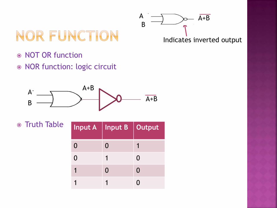
NOT OR function
NOR function: logic circuit
Truth Table
A
B
A+B
A+B
Indicates inverted output
A+B
Input A Input B Output
0 0 1
0 1 0
1 0 0
1 1 0
A
B

1. Draw truth tables for the NAND, NOR and
XOR logic gates
2. Draw the circuit symbols for the AND, OR,
NOT, NAND NOR and XOR logic gates
3. EXPRESS q IN TERMS OF Boolean variables
A, B and C for the arrangements of logic
gates below:
A
B
C
Q

1. Construct a logic circuit using only NAND
gates for the Boolean expression (A.B).(B.A)
2. Construct logic circuits, using only NOR
gates, for the Boolean expression
(A+B)+(A+B)

Enable Boolean expressions to be converted to forms requiring only the OR and NOT functions or only the AND and NOT functions
This means any Boolean expression may be implemented using only OR gates and NOT gates [NOR gates] or using only AND gates and NOT gates [NAND gates]
NAND and NOR gates may be used as NOT gates by connecting all the gate inputs together

Therefore, NOR gates alone or NAND gates
alone can implement any Boolean function
The fabrication on a single chip of many NOR
gates or many NAND gates is possible with
integrated circuit technology
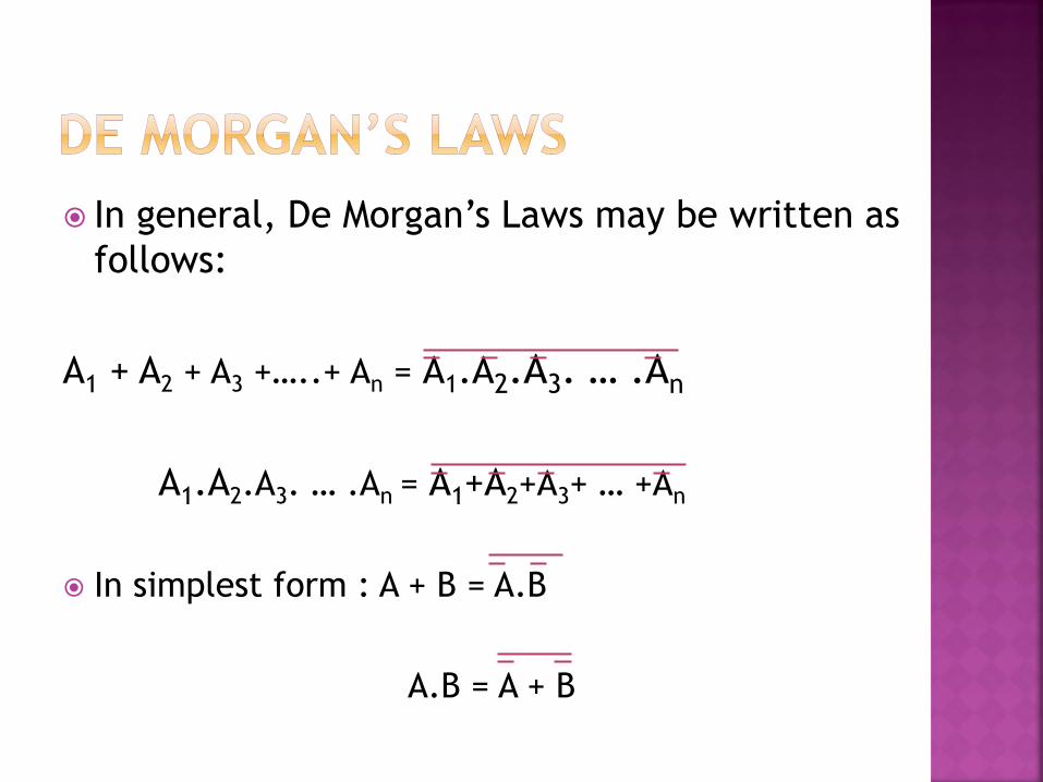
In general, De Morgan’s Laws may be written as
follows:
A1 + A2 + A3 +…..+ An = A1.A2.A3. … .An
A1.A2.A3. … .An = A1+A2+A3+ … +An
In simplest form : A + B = A.B
A.B = A + B
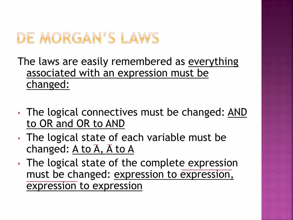
The laws are easily remembered as everything associated with an expression must be changed:
• The logical connectives must be changed: AND to OR and OR to AND
• The logical state of each variable must be changed: A to A, A to A
• The logical state of the complete expression must be changed: expression to expression, expression to expression

1. Show that A.B+A.B = (A+B).(A+B), where A and B are Boolean variables
2. Show that (A+B).(A+B) = (A+B).(A+B) by using A.A = B.B = 0
3. Simplify 1.B where B is a Boolean variable and 1 is a Boolean constant
4. Show that (A.A.B).(B.A.B) = A.B + B.A
5. Output Q = A.(C+D)+B.(C+D) where A, B, C and D are Boolean inputs. Show how it is possible to use just four NAND gates to produce output Q from A, B, C and D. One of the NAND gates is used as a NOT gate

In this topic we have covered:
• Boolean variables may have two discrete possible values, e.g. true or false, 1 or 0
• A truth table shows the result of applying a logical function to all possible input combinations
• OR function (+): output is true if either or both inputs are true
• AND function (.): the output is true if all inputs are true
• NOT function ( ): the output is the inversion of the input
• XOR function( ): the output is true if either input is true but not if both are true

In this topic we have covered:
• NAND function (NOT AND): the output is true if any input is false
• NOR function (NOT OR): the output is true only when all inputs are false
• Logic gates perform Boolean functions such as AND, OR and NOT
• Output Q is expressed in terms of Boolean inputs X, Y, Z etc. and Boolean functions
• De Morgan’s Laws: A+B = A.B and A.B=A+B
• To simplify a logical expression use a truth table to write down input combinations that make the output 1 then use De Morgan’s Law to produce a solution in NAND or NOR
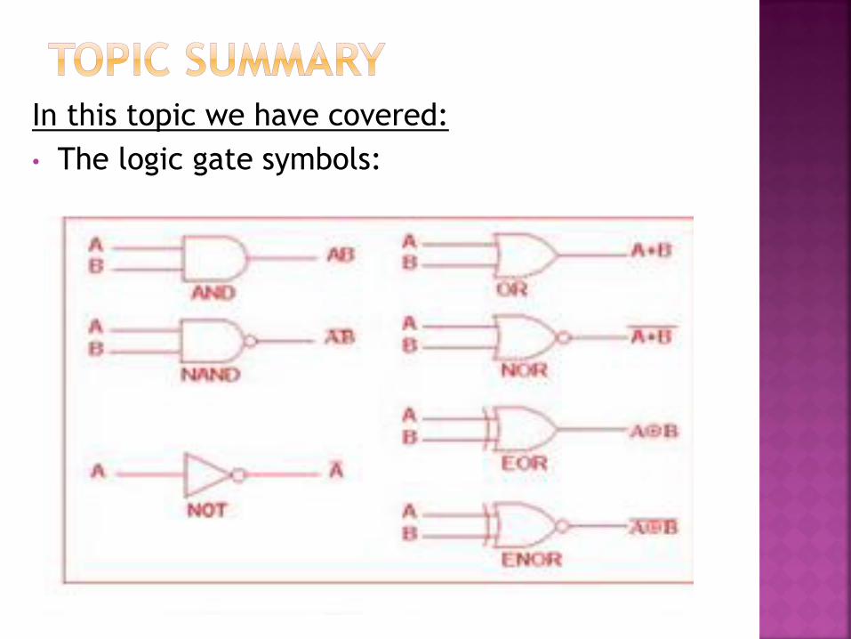
In this topic we have covered:
• The logic gate symbols: