note: when revising this procedure ensure latest · pdf file... when revising this procedure...
TRANSCRIPT


- 2 -
NOTE: WHEN REVISING THIS PROCEDURE ENSURE LATEST REVISION IS UPLOADED TO THE PUBLIC OASIS SITE.
Revision No. Revision History Date Revised 0 Original Issue 12/14/2005 1 Added signature page, revision history
page, generator rating information and a section on communicating the use of the document.
03/09/2007
2 Added section and table for rigid bus ratings. Also removed the section associated with generator rating. This is included in the ratings methodology procedure for generators.
11/01/2007
3
Removed the reference to generators in the
06/18/2008
4 Added section on high temperature conductors within the Overhead conductor section II.1.
12/12/2008
5 Added section on ratings for 6 inch bus in table in the appendix.
02/25/2009
6 Revised transformer section for thermal overload to refer to C57.92 and added series reactors to the procedures.
06/05/2009
7 Added IEEE standard references for equipment ratings associated with transformers, switches, circuit breakers, and reactive devices.
06/26/2009
8 Provided minor changes to provide more precise clarification on data added more clarity associated with FAC-009 Communication and revised Appendix A
01/22/2010
9 Provided editorial change on the cover sheet date and clarification in the purpose section.
03/24/2010
10 Revised description of short term rating application
04/30/2010
11 Added the clarification associated with operating transmission element to NESC requirements
01/16/2012
12 Clarified that Methodology applies to entire AECI system footprintthat formula would be used unless Mfg. data to contrary. Other minor editorial cleanup (spacing, etc.)
04/04/2012
13 Changed title; Refined limited element language; Added clarifying language for ratings being continuous for PRC-023.
12/14/2012

- 3 -
CAN 0018; Clarified ratings duration.14 Updated switch rating IEEE standard
reference C37.37-1979 to1996; Clarified that AECI will calculate switch loadability factor from C37.37-1996, Added ambient temperature for switch ratings
10/04/2013
15 Temperature adjusted and short-term limit detail added. Updated appendix F. Added disclaimer to purpose.
06/09/2014
16 Added jumpers and rigid bus conductors to Appendix F. Clarified circuit breaker rating detail in Section II.6.
09/15/2014
17
Corrected spring/fall switch ratings to reflect 87F rather than 86F ambient. Correction made in narrative paragraph and in Appendix E tables.
09/23/2016
18 Added statement in section III stating the MANTIS database serves as the source of limits for EMS and RTCA.
02/15/2017
19 Reformatted Appendix A Conductor Ratings table; Corrected 1431, ACSR 45/7 ratings
04/27/2017
20 Added jumper ratings to conductor table in Appendix A
10/11/2017
21 Clarified that relay ratings calculations are based upon 1.0 p.u. voltage.
11/1/2017
- 4 -
Facility Rating Methodology And Communication.
Contents
I. Purpose / Introduction ............................................................................................. - 5 - I.1 Limiting Factor .................................................................................. - 5 - I.2 Ratings Duration ............................................................................... - 5 -
II. Facility Rating Methodology .................................................................................... - 6 - II.1 Overhead Conductors ....................................................................... - 6 - II.2 Power Transformers.......................................................................... - 9 - II.3 Switches ............................................................................................. - 9 - II.4 Wave Traps ...................................................................................... - 10 - II.5 Current Transformers ..................................................................... - 11 - II.6 Circuit Breakers ............................................................................... - 11 - II.7 Relays and Protective Equipment .................................................. - 12 - II.8 Series and Shunt Reactive Devices. .............................................. - 12 -
III. Communication of Facility Methodology .............................................................. - 12 -
Appendix A: Ratings of Typical Conductors .................................................................... - 14 -
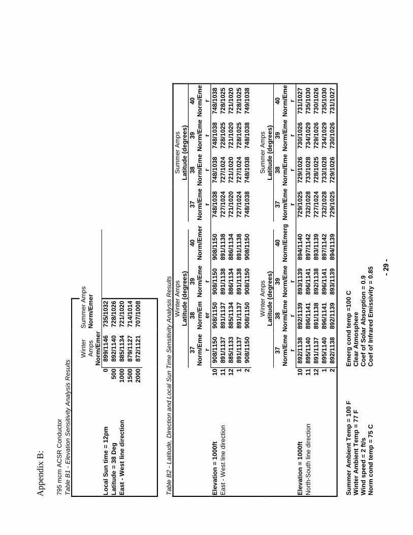
Appendix B: ........................................................................................................................ - 29 - Table B1 - Elevation Sensitivity Analysis Results .................................... - 29 - Table B2 - Latitude, Direction and Local Sun Time Sensitivity Analysis
Results ............................................................................................. - 29 -
Appendix C: Maximum Temperatures .............................................................................. - 30 -
Appendix D: Wavetrap Loadability Factor vs Ambient Temperature ............................. - 31 -
Appendix E: Short Term Loading Guidelines .................................................................. - 32 -
Appendix F: Component Rating Summary for AECI and Member G&T Systems .......... - 33 -

- 5 -
I. Purpose / Introduction
The purpose of this document is to ensure that Facility Ratings used in the reliable planning technically
sound principles.
This rating criteria applies to transmission circuits transmission system (referred to collectively as the AECI system) operated at 69kV and above, beginning at the high side terminals of generator step-up transformers, and specifies how to develop the maximum rating of each element of a transmission circuit. Although AECI and its m -BES elements, this in no way increases the scope of NERC Standards beyond what is stated in the applicability of each Standard. This rating criteria specifically addresses overhead conductors, power transformers, switches, wave traps, current transformers, circuit breakers, relays and protective equipment, and series and shunt reactive elements. Where appropriate normal, emergency, short term emergency, and seasonal ratings are developed. Short term emergency ratings and response actions may be developed on a case by case basis. This allows flexibility in the operating horizon and time, post-contingency, for the System Operator to take remedial action such as re-dispatch of generation or switching to reduce the element loading to within the continuous emergency rating. This discussion also extends the overhead conductor section to include bus conductors. A summary page of rating for equipment used in transmission other than conductors is provided in Appendix F. I.1 Limiting Factor
The overall rating of a transmission circuit will be established by the most limiting series connected device within that circuit. Series connected devices may include, but not be limited to, overhead conductors, switches, wave traps, current transformers, circuit breakers, relays and protective equipment (including primary fuses), and/or reactive devices. In the case of a transmission circuit that interconnects with another utility, AECI shall coordinate the overall rating of that circuit with the utility involved.
rating or the equipment rating of the interconnecting utility.
I.2 Ratings Duration
Unless otherwise stated, (e.g. short-methodology detailed in this Facility Rating Methodology and Communication document are to be considered as continuous ratings.
- 6 -
II. Facility Rating Methodology
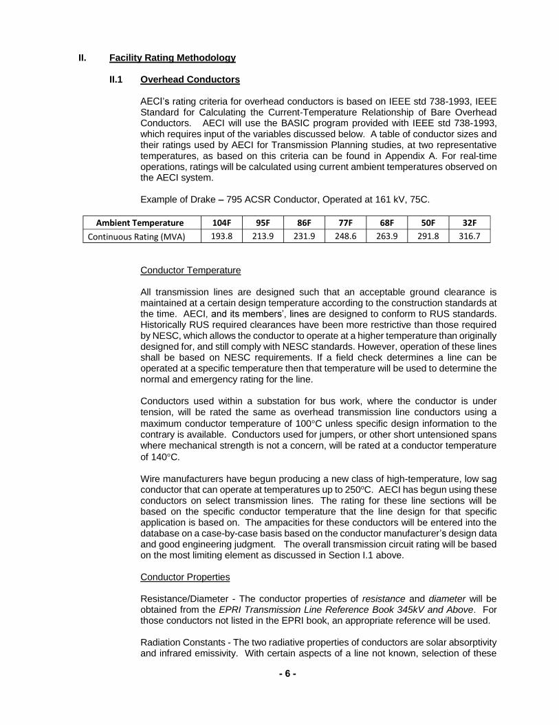
II.1 Overhead Conductors
rating criteria for overhead conductors is based on IEEE std 738-1993, IEEE Standard for Calculating the Current-Temperature Relationship of Bare Overhead Conductors. AECI will use the BASIC program provided with IEEE std 738-1993, which requires input of the variables discussed below. A table of conductor sizes and their ratings used by AECI for Transmission Planning studies, at two representative temperatures, as based on this criteria can be found in Appendix A. For real-time operations, ratings will be calculated using current ambient temperatures observed on the AECI system. Example of Drake 795 ACSR Conductor, Operated at 161 kV, 75C.
Ambient Temperature 104F 95F 86F 77F 68F 50F 32F Continuous Rating (MVA) 193.8 213.9 231.9 248.6 263.9 291.8 316.7
Conductor Temperature All transmission lines are designed such that an acceptable ground clearance is maintained at a certain design temperature according to the construction standards at the time. AECI are designed to conform to RUS standards. Historically RUS required clearances have been more restrictive than those required by NESC, which allows the conductor to operate at a higher temperature than originally designed for, and still comply with NESC standards. However, operation of these lines shall be based on NESC requirements. If a field check determines a line can be operated at a specific temperature then that temperature will be used to determine the normal and emergency rating for the line. Conductors used within a substation for bus work, where the conductor is under tension, will be rated the same as overhead transmission line conductors using a maximum conductor temperature of 100 C unless specific design information to the contrary is available. Conductors used for jumpers, or other short untensioned spans where mechanical strength is not a concern, will be rated at a conductor temperature of 140 C. Wire manufacturers have begun producing a new class of high-temperature, low sag conductor that can operate at temperatures up to 250oC. AECI has begun using these conductors on select transmission lines. The rating for these line sections will be based on the specific conductor temperature that the line design for that specific application is based on. The ampacities for these conductors will be entered into the database on a case-by-case basis based on the conductor manufacturer design data and good engineering judgment. The overall transmission circuit rating will be based on the most limiting element as discussed in Section I.1 above. Conductor Properties Resistance/Diameter - The conductor properties of resistance and diameter will be obtained from the EPRI Transmission Line Reference Book 345kV and Above. For those conductors not listed in the EPRI book, an appropriate reference will be used. Radiation Constants - The two radiative properties of conductors are solar absorptivity and infrared emissivity. With certain aspects of a line not known, selection of these

- 7 -
two variables can be highly subjective. The Solar Absorptivity coefficient represents the fraction of incident solar radiant energy that is absorbed by the conductor surface. The solar absorptivity coefficient varies between about 0.2 to about 0.9, with higher values indicating that more solar energy is being absorbed by the conductor. As a conductor ages, the solar absorptivity, or the amount of solar energy absorbed by the conductor increases, which decreases the MVA rating of the conductor. The Infrared Emissivity coefficient represents the ratio of radiant energy emitted by the conductor surface to the infrared radiant energy emitted by a blackbody at the same temperature, and can vary between about 0.2 to about 0.9. As a conductor ages, the infrared emissivity, or ability of the conductor to radiate heat energy to its surroundings increases, which increases the MVA rating of the conductor. According to IEEE Std. 738-1993 the absorptivity generally stays higher than the emissivity over the life of a conductor. To eliminate the need to update conductor ratings annually, and to provide a conservative value for conductor ratings, AECI has chosen to use 0.9 for absorptivity and 0.85 for emissivity for all conductors. Geographic Location Elevation - Elevation of a conductor above sea level is another variable used in the calculation of conductor capacity. The elevation of a conductor affects the amount of solar energy absorbed and the amount of energy given off to the air around it. The results of a sensitivity analysis (Appendix B, Table B1) show this effect is small compared to many of the other variables, therefore attempts to acquire elevations for specific transmission lines will not be made. A default elevation of 1000 feet as being a fairly representative elevation for the AECI system footprint will be used for all conductors. Latitude - The latitude of a conductor affects the amount of solar energy absorbed by a transmission line. A default latitude of 38 degrees, the approximate center latitude of the AECI system footprint, will be used for all lines. Table B2 in Appendix B shows the effects of latitude on a conductors' current capacity. Direction and Local Sun Time - The direction of a conductor, classified as either North-South or East-West by the IEEE program, describes the general direction of a transmission line. Local Sun time describes the overhead position of the sun. These two variables separately and together effect, but not to a large degree, the amount of solar energy absorbed by the conductor. A direction of North-South is recommended as the default for Associated and member G&T transmission lines. This reduces the effect of Local Sun Time on the capacity, which is given a default value of 12 noon. Table B2 in Appendix B shows the effects of direction and local sun time on a conductors' current capacity. Atmosphere - Atmospheric conditions also have an effect on the rating of a conductor. The IEEE program options are clear or industrial atmosphere. An industrial atmosphere will increase the rating of a transmission line due to decreased solar absorption. Since the majority of AECIclear atmosphere is recommended as the default for AECI and member G&T transmission lines.
- 8 -
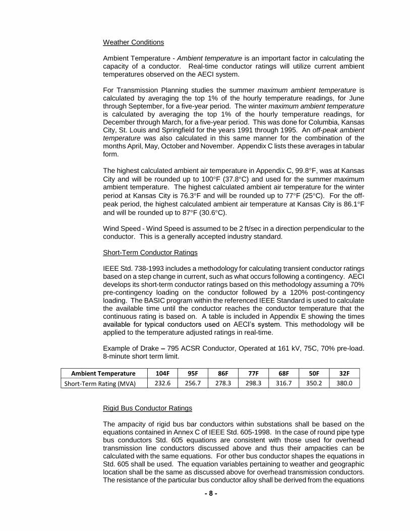
Weather Conditions Ambient Temperature - Ambient temperature is an important factor in calculating the capacity of a conductor. Real-time conductor ratings will utilize current ambient temperatures observed on the AECI system. For Transmission Planning studies the summer maximum ambient temperature is calculated by averaging the top 1% of the hourly temperature readings, for June through September, for a five-year period. The winter maximum ambient temperature is calculated by averaging the top 1% of the hourly temperature readings, for December through March, for a five-year period. This was done for Columbia, Kansas City, St. Louis and Springfield for the years 1991 through 1995. An off-peak ambient temperature was also calculated in this same manner for the combination of the months April, May, October and November. Appendix C lists these averages in tabular form. The highest calculated ambient air temperature in Appendix C, 99.8 F, was at Kansas City and will be rounded up to 100 F (37.8 C) and used for the summer maximum ambient temperature. The highest calculated ambient air temperature for the winter period at Kansas City is 76.3 F and will be rounded up to 77 F (25 C). For the off-peak period, the highest calculated ambient air temperature at Kansas City is 86.1 F and will be rounded up to 87 F (30.6 C). Wind Speed - Wind Speed is assumed to be 2 ft/sec in a direction perpendicular to the conductor. This is a generally accepted industry standard. Short-Term Conductor Ratings IEEE Std. 738-1993 includes a methodology for calculating transient conductor ratings based on a step change in current, such as what occurs following a contingency. AECI develops its short-term conductor ratings based on this methodology assuming a 70% pre-contingency loading on the conductor followed by a 120% post-contingency loading. The BASIC program within the referenced IEEE Standard is used to calculate the available time until the conductor reaches the conductor temperature that the continuous rating is based on. A table is included in Appendix E showing the times
This methodology will be applied to the temperature adjusted ratings in real-time. Example of Drake 795 ACSR Conductor, Operated at 161 kV, 75C, 70% pre-load. 8-minute short term limit.
Ambient Temperature 104F 95F 86F 77F 68F 50F 32F Short-Term Rating (MVA) 232.6 256.7 278.3 298.3 316.7 350.2 380.0
Rigid Bus Conductor Ratings The ampacity of rigid bus bar conductors within substations shall be based on the equations contained in Annex C of IEEE Std. 605-1998. In the case of round pipe type bus conductors Std. 605 equations are consistent with those used for overhead transmission line conductors discussed above and thus their ampacities can be calculated with the same equations. For other bus conductor shapes the equations in Std. 605 shall be used. The equation variables pertaining to weather and geographic location shall be the same as discussed above for overhead transmission conductors. The resistance of the particular bus conductor alloy shall be derived from the equations

- 9 -
in C.4.4 of Std. 605. The absorptivity and emissivity constants shall each be assumed to be 0.5 as suggested in Std. 605 as being representative of aluminum conductors after extended outdoor exposure. According to Std. 605 aluminum alloy and copper conductors can be operated at 90o C continuously without appreciable loss of strength and can be operated at 100o C under emergency conditions with some annealing. Based on this AECI shall use 90o C for its normal rating and 100o C for its 2-hour emergency rating. A table is included in Appendix A.
II.2 Power Transformers
AECI Power Transformer ratings are based on IEEE C57.12.00-1980 and IEEE C57.92-1981. For real-time operations, ratings will utilize current ambient temperatures within the calculation of the power transformer limits. As the IEEE C57.92-1981 ratings table are based upon ambient temperatures, the continuous rating adjusted for real-time ambient conditions will be based upon a conservative application of 100% nameplate pre-loading, normal loss of life, and 24 hours of peak load, with values not to exceed name-plate rating at temperatures above 86F. Example for 161/69 kV Transformer OFAF, 65C Temp Rise, Name-plate 56 MVA.
Ambient Temperature 104F 95F 86F 77F 68F 50F 32F Continuous Rating (MVA) 56.0 56.0 56.0 58.0 59.9 63.8 67.8
Power transformers are rated based on average daily temperatures due to their relatively high thermal inertia constants. In a manner similar to the daily maximum temperature selections under the conductor rating sections, Transmission Planning studies apply daily averages for AECI and have been established for three seasons; summer 32o C, spring/fall 25o C, and winter 18o C. AECI has developed a higher winter season rating for its transformers based on ANSI Standard C57.92-1981. As per the capability tables in C57.92 an OA/FOA/FOA transformer, at an average ambient temperature of 18o C, can carry 115% of its maximum nameplate rating for 8 hours with no loss of life. Using the same tables an OA/FA/FA transformer has a 117% capability. For the sake of consistency AECI has adopted the 115% multiplier to establish the winter rating for all transformers.
AECI will use ANSI/IEEE Standard C57.92-1981 Tables 3&5 to determine the short term ratings for transformers. The % loss of life noted within the table shall be
This table is based upon ambient conditions, which will be utilized in real-time operations. The Short-Term ratings used will not exceed 194% of name-plate. Example for 161/69 kV Transformer, OFAF 65C Temp Rise, Name-plate 56 MVA, 70% pre-load.
Ambient Temperature 104F 95F 86F 77F 68F 50F 32F 2 Hour Short Term (MVA) 66.6 69.4 71.7 73.9 76.2 80.1 83.4
II.3 Switches
AECI -Voltage Switch ratings are based on IEEE C37.30-1971, IEEE C37.32-1972 and IEEE C37.37-1996 Unless specific manufacturer data is available to the contrary, to determine the seasonal allowable continuous current capability of an air switch, AECI will use the manufacturers continuous nameplate rating with appropriate Loadability Factor from
- 10 -
Figure 1 of IEEE C37.37 for both normal and emergency ratings, (using the same ambient temperatures as for Overhead Conductors) unless specific circumstances arise that may require a higher rating to be developed. The IEEE Standards C37.30-1971 and C37.37-1979 will be used as the basis for these higher ratings.
AECI has developed short term, 15 minute, ratings for its disconnect switches based on the most limiting switch part class as identified in the C37.37 loadability guide. Based on C37.30 requirements, the temperature rise of a switch part due to current flow is determined by the square of the current increase:
(Iactual/Irated)2 = Temperature Rise/Rated Temperature Rise
The standard also states that at a constant current, the temperature approaches its steady state value at an exponential rate and suggests 30 minutes as a conservative switch part time constant. In equation form then a short time rating multiplier can be established by:
(1/RatTempRise*(AvailTempRise/(1-e-t/T)+(TempMax-AmbTemp)),0.5 where RatTempRise = Switch Part Rated Temperature Rise AvailTempRise = RatTempRise less actual operating temperature t = emergency loading time interval desired in minutes T = switch part time constant (30 minutes) TempMax= Switch part maximum operating temperature AmbTemp = ambient temperature
Using these equations AECI has established the 15 minute short term multipliers for summer as 152%, spring/fall as 152%, and winter as 167%. These are also shown in Appendix E.
II.4 Wave Traps
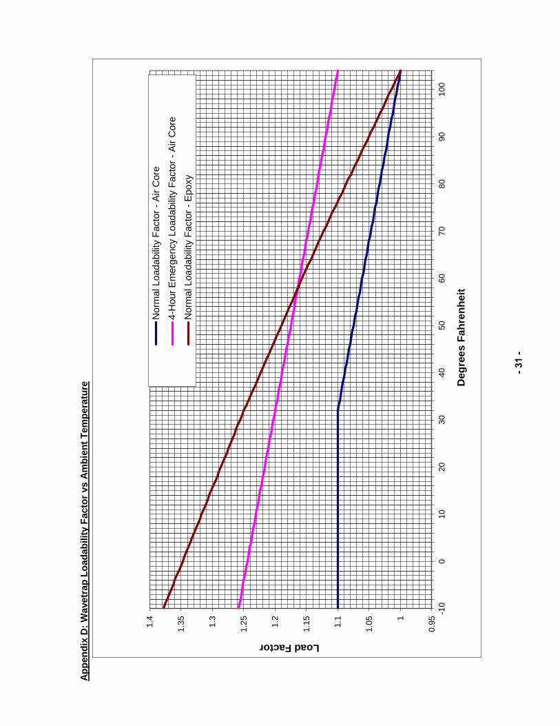
AECI two types of wave traps commonly in use; the older air-core type, covered by ANSI Standard C93.3-1981, Requirements for Power-Line Carrier Line Traps, and a newer epoxy-encapsulated type, which are not covered by an ANSI/IEEE standard. The loadability guidelines provided by Trench Electric will be used for epoxy-encapsulated wave traps. A graphical representation of the loadability factors is in Appendix D. A wave trap's rating is simply the nameplate rating multiplied by the appropriate loadability factor. The emergency current rating represents a level of current that should be maintained for no longer than four hours per load cycle, with the wave trap loading being at or below the normal current loading for at least two hours before the emergency load cycle occurs. AECI's normal and emergency rating for air-core wave traps will be based on the '4 Hour Emergency' loadability factors from the graph in Appendix D. For a summer rating based on a 100 F ambient, the factor will be 1.11 and likewise, for a winter rating based on a 77 F ambient, the factor will be 1.14. AECI will use the normal rating loadability factors supplied by Trench Electric, for normal and emergency rating of epoxy encapsulated wave traps. For a summer rating on a 100 F ambient, the factor will be 1.02 and likewise, for a winter rating on a 77 F ambient, the factor will be 1.09. (AECI will consider these ratings as continuous ratings.) AECI has developed short term, 15 minute, ratings for its wave traps developed with the same curves and loadability information discussed above. From this information AECI has established the 15-minute short term multipliers as follows:
- 11 -
Air core traps summer--141%, spring/fall--142%, and winter--144% Epoxy traps summer 109%, spring/fall 120%, and winter 128%. These are also shown in Appendix E.
II.5 Current Transformers
The two types of current transformers are the separately mounted type or the bushing type. The basis of this current transformer criterion is ANSI/IEEE C57.13-1978, IEEE Standard Requirements for Instrument Transformers. Separately mounted CTs will have normal and emergency ratings based on the primary current rating for the ratio being used and the average ambient adjusted Continuous-Thermal-Current rating factor supplied by the specific current transformer manufacturer. Rating of bushing type CTs is dependent upon the environment within the device they are mounted. Unless specific manufacturer data is available to the contrary, AECI will use the rating formulas below based on a Westinghouse Electric technical paper
rrent Transformers Used with Power Circuit Breakers and Powe Rating Factor = R.F. = (Ipa/Ict)1/2 CT current rating = R.F. * Ict or CT current rating = (Ipa * Ict)1/2
where Ipa = Power apparatus continuous current rating (amps) Ict = Primary current rating of bushing current transformer ratio used (amps) The results calculated from this equation should be so limited that the maximum rating factor does not exceed 2.0 and that the continuous current rating of the breaker is not exceeded.
The Westinghouse technical paper referenced above states that short term emergency ratings as permitted by IEEE C37.010, can be applied to bushing CTs. On this basis, AECI will use the short term multipliers developed in the Circuit Breaker section below, for bushing CTs.
II.6 Circuit Breakers
AECI -Voltage Circuit Breaker ratings are based on IEEE C37.06-1979 and IEEE C37.010-1979 AECI will use the manufacturer s continuous nameplate rating as the basis for both normal and emergency thermal ratings, for all seasons. IEEE Standard C37.010-1979 allows for higher loadability at ambient temperatures below 86 F. A loadability factor of 1.04 will be used during temperatures of 86 F to 69 F, and 1.07 for temperatures 68 F and below.
AECI has developed short term, 15 minute, thermal ratings for its circuit breakers developed with the same equations utilized above for disconnect switches except, as per C37.010, the temperature rise of breaker parts is proportional to the 1.8 power of the current rise. Using these equations AECI has established the 15 minute short term multipliers for summer as 148%, spring/fall as 151%, and winter as 153%. These are
- 12 -
also shown in Appendix E. II.7 Relays and Protective Equipment
Relays can impose limits on transmission power flow in two ways. First, the current flow through the relay, as determined by the transmission circuit current flow in
internal thermal capabilities. Secondly, the relay distance setting could initiate an undesired line trip during abnormally high transmission circuit power flows. To address this situation, applicable current transformer ratios chosen, shall be such that any underlying relay s loadability capability PRC-023 Transmission Relay Loadability Procedure. voltage of 1.0 per unit shall be used.) Primary fuses 69 kV and above system are used to protect 69 kV to
protect shunt loads. P are rated according to the .
II.8 Series and Shunt Reactive Devices.
continuous nameplate rating for the summer season. Series reactors, like power transformers, are rated based on average daily temperatures. For spring/fall and winter seasons the multipliers in ANSI C57.99-1965, Table 1, are used to adjust the
temperature. See Section II.2 above. Series reactors are specified, designed and applied according to IEEE C57.16-1996. Short term emergency ratings for series reactors are based on the applicable ANSI C57.99-1965, Table 2 to give normal life expectancy, for the time period desired. Since Table 2 of C57.99 is for summer average daily temperatures, the spring/fall and winter short-term emergency ratings will use the multipliers of Table 1 to adjust the short-term rating to the applicable season. Shunt reactors are specified, designed and applied according to IEEE C57.21-1981. Shunt capacitors are specified, designed and applied according to IEEE 1036-1992.
III. Communication of Facility Methodology
This document shall be posted on the AECI Public OASIS domain for review by the Reliability Coordinator, Transmission Operators, Transmission Planners and Planning Authorities that have responsibilities within the AECI BES area. AECI Operations and Planning engineers shall ensure that these methodologies are followed when preparing engineering studies for AECI and its Member-Owner Cooperatives. AECI maintains a Modeling and Network Transmission Information System (MANTIS) database of transmission system equipment characteristics that includes, among other
equipment developed using this methodology. MANTIS serves as the source of information for AECI EMS and Real-Time Contingency Analysis limits. AECI participates in the annual SERC LTSG load flow databank update and the subsequent MMWG model building effort.
atings in those models is derived from the AECI Transmission Database.
- 13 -
IV. Handling of Comments from Other Entities AECI will provide a written response within 45 days to any written comments provided from an RC, TO, TP, or PA associated with this document.
- 14 -
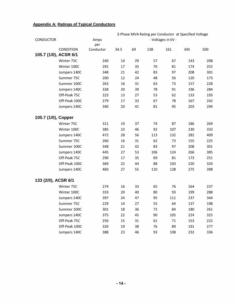
Appendix A: Ratings of Typical Conductors
3-Phase MVA Rating per Conductor at Specified Voltage CONDUCTOR Amps - Voltages in kV -
CONDITION per
Conductor 34.5 69 138 161 345 500 105.7 (1/0), ACSR 6/1 Winter 75C 240 14 29 57 67 143 208
Winter 100C 291 17 35 70 81 174 252 Jumpers 140C 348 21 42 83 97 208 301 Summer 75C 200 12 24 48 56 120 173 Summer 100C 263 16 31 63 73 157 228 Jumpers 140C 328 20 39 78 91 196 284 Off-Peak 75C 223 13 27 53 62 133 193 Off-Peak 100C 279 17 33 67 78 167 242 Jumpers 140C 340 20 41 81 95 203 294
105.7 (1/0), Copper Winter 75C 311 19 37 74 87 186 269
Winter 100C 385 23 46 92 107 230 333 Jumpers 140C 472 28 56 113 132 282 409 Summer 75C 260 16 31 62 73 155 225 Summer 100C 348 21 42 83 97 208 301 Jumpers 140C 445 27 53 106 124 266 385 Off-Peak 75C 290 17 35 69 81 173 251 Off-Peak 100C 369 22 44 88 103 220 320 Jumpers 140C 460 27 55 110 128 275 398
133 (2/0), ACSR 6/1 Winter 75C 274 16 33 65 76 164 237
Winter 100C 333 20 40 80 93 199 288 Jumpers 140C 397 24 47 95 111 237 344 Summer 75C 229 14 27 55 64 137 198 Summer 100C 301 18 36 72 84 180 261 Jumpers 140C 375 22 45 90 105 224 325 Off-Peak 75C 256 15 31 61 71 153 222 Off-Peak 100C 320 19 38 76 89 191 277 Jumpers 140C 388 23 46 93 108 232 336

- 15 -
3-Phase MVA Rating per Conductor at Specified Voltage CONDUCTOR Amps - Voltages in kV -
CONDITION per
Conductor 34.5 69 138 161 345 500 133.1 (2/0), Copper Winter 75C 360 22 43 86 100 215 312
Winter 100C 447 27 53 107 125 267 387 Jumpers 140C 549 33 66 131 153 328 475 Summer 75C 300 18 36 72 84 179 260 Summer 100C 404 24 48 97 113 241 350 Jumpers 140C 519 31 62 124 145 310 449 Off-Peak 75C 335 20 40 80 93 200 290 Off-Peak 100C 429 26 51 103 120 256 372 Jumpers 140C 536 32 64 128 149 320 464
167.7 (3/0), ACSR 6/1 Winter 75C 314 19 38 75 88 188 272
Winter 100C 381 23 46 91 106 228 330 Jumpers 140C 454 27 54 109 127 271 393 Summer 75C 261 16 31 62 73 156 226 Summer 100C 344 21 41 82 96 206 298 Jumpers 140C 429 26 51 103 120 256 372 Off-Peak 75C 292 17 35 70 81 174 253 Off-Peak 100C 366 22 44 87 102 219 317 Jumpers 140C 443 26 53 106 124 265 384
211.3, ACSR 12/7 Winter 75C 355 21 42 85 99 212 307
Winter 100C 424 25 51 101 118 253 367 Jumpers 140C 494 30 59 118 138 295 428 Summer 75C 294 18 35 70 82 176 255 Summer 100C 383 23 46 92 107 229 332 Jumpers 140C 467 28 56 112 130 279 404 Off-Peak 75C 330 20 39 79 92 197 286 Off-Peak 100C 407 24 49 97 113 243 352 Jumpers 140C 483 29 58 115 135 289 418
- 16 -
3-Phase MVA Rating per Conductor at Specified Voltage CONDUCTOR Amps - Voltages in kV -
CONDITION per
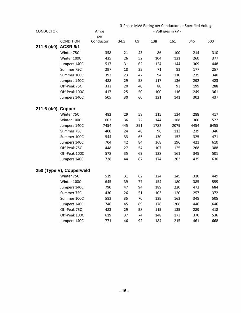
Conductor 34.5 69 138 161 345 500 211.6 (4/0), ACSR 6/1 Winter 75C 358 21 43 86 100 214 310
Winter 100C 435 26 52 104 121 260 377
Jumpers 140C 517 31 62 124 144 309 448
Summer 75C 297 18 35 71 83 177 257
Summer 100C 393 23 47 94 110 235 340
Jumpers 140C 488 29 58 117 136 292 423
Off-Peak 75C 333 20 40 80 93 199 288
Off-Peak 100C 417 25 50 100 116 249 361
Jumpers 140C 505 30 60 121 141 302 437
211.6 (4/0), Copper Winter 75C 482 29 58 115 134 288 417
Winter 100C 603 36 72 144 168 360 522
Jumpers 140C 7454 445 891 1782 2079 4454 6455
Summer 75C 400 24 48 96 112 239 346
Summer 100C 544 33 65 130 152 325 471
Jumpers 140C 704 42 84 168 196 421 610
Off-Peak 75C 448 27 54 107 125 268 388
Off-Peak 100C 578 35 69 138 161 345 501
Jumpers 140C 728 44 87 174 203 435 630
250 (Type V), Copperweld Winter 75C 519 31 62 124 145 310 449
Winter 100C 645 39 77 154 180 385 559
Jumpers 140C 790 47 94 189 220 472 684
Summer 75C 430 26 51 103 120 257 372
Summer 100C 583 35 70 139 163 348 505
Jumpers 140C 746 45 89 178 208 446 646
Off-Peak 75C 483 29 58 115 135 289 418
Off-Peak 100C 619 37 74 148 173 370 536
Jumpers 140C 771 46 92 184 215 461 668

- 17 -
3-Phase MVA Rating per Conductor at Specified Voltage CONDUCTOR Amps - Voltages in kV -
CONDITION per
Conductor 34.5 69 138 161 345 500 266.8, ACSR 26/7 Winter 75C 449 27 54 107 125 268 389
Winter 100C 563 34 67 135 157 336 488
Jumpers 140C 696 42 83 166 194 416 603
Summer 75C 371 22 44 89 103 222 321
Summer 100C 508 30 61 121 142 304 440
Jumpers 140C 658 39 79 157 183 393 570
Off-Peak 75C 417 25 50 100 116 249 361
Off-Peak 100C 540 32 65 129 151 323 468
Jumpers 140C 680 41 81 163 190 406 589 266.8, ACSS 26/7 Winter 75C 459 27 55 110 128 274 398
Winter 100C 576 34 69 138 161 344 499
Jumpers 140C 712 43 85 170 199 425 617
Summer 75C 380 23 45 91 106 227 329
Summer 100C 520 31 62 124 145 311 450
Jumpers 140C 672 40 80 161 187 402 582
Off-Peak 75C 427 26 51 102 119 255 370
Off-Peak 100C 552 33 66 132 154 330 478
Jumpers 140C 695 42 83 166 194 415 602
335.6 (2-3/0), ACSR 2-6/1 Winter 75C 503 30 60 120 140 301 436
Winter 100C 618 37 74 148 172 369 535
Jumpers 140C 744 44 89 178 207 445 644
Summer 75C 414 25 49 99 115 247 359
Summer 100C 557 33 67 133 155 333 482
Jumpers 140C 703 42 84 168 196 420 609
Off-Peak 75C 466 28 56 111 130 278 404
Off-Peak 100C 593 35 71 142 165 354 514
Jumpers 140C 727 43 87 174 203 434 630
- 18 -
3-Phase MVA Rating per Conductor at Specified Voltage CONDUCTOR Amps - Voltages in kV -
CONDITION per
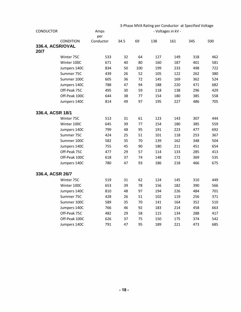
Conductor 34.5 69 138 161 345 500 336.4, ACSR/OVAL 20/7 Winter 75C 533 32 64 127 149 318 462
Winter 100C 671 40 80 160 187 401 581
Jumpers 140C 834 50 100 199 233 498 722
Summer 75C 439 26 52 105 122 262 380
Summer 100C 605 36 72 145 169 362 524
Jumpers 140C 788 47 94 188 220 471 682
Off-Peak 75C 495 30 59 118 138 296 429
Off-Peak 100C 644 38 77 154 180 385 558
Jumpers 140C 814 49 97 195 227 486 705
336.4, ACSR 18/1 Winter 75C 513 31 61 123 143 307 444
Winter 100C 645 39 77 154 180 385 559
Jumpers 140C 799 48 95 191 223 477 692
Summer 75C 424 25 51 101 118 253 367
Summer 100C 582 35 70 139 162 348 504
Jumpers 140C 755 45 90 180 211 451 654
Off-Peak 75C 477 29 57 114 133 285 413
Off-Peak 100C 618 37 74 148 172 369 535
Jumpers 140C 780 47 93 186 218 466 675
336.4, ACSR 26/7 Winter 75C 519 31 62 124 145 310 449
Winter 100C 653 39 78 156 182 390 566
Jumpers 140C 810 48 97 194 226 484 701
Summer 75C 428 26 51 102 119 256 371
Summer 100C 589 35 70 141 164 352 510
Jumpers 140C 766 46 92 183 214 458 663
Off-Peak 75C 482 29 58 115 134 288 417
Off-Peak 100C 626 37 75 150 175 374 542
Jumpers 140C 791 47 95 189 221 473 685
- 19 -
3-Phase MVA Rating per Conductor at Specified Voltage CONDUCTOR Amps - Voltages in kV -
CONDITION per
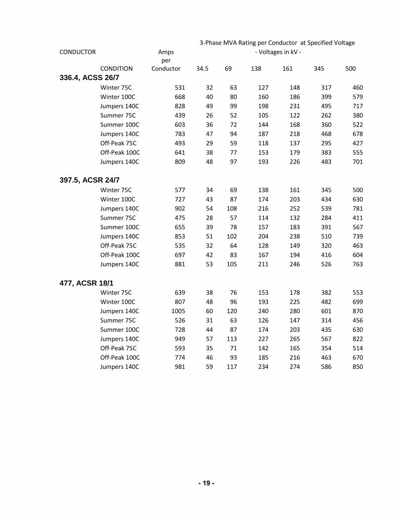
Conductor 34.5 69 138 161 345 500 336.4, ACSS 26/7 Winter 75C 531 32 63 127 148 317 460
Winter 100C 668 40 80 160 186 399 579
Jumpers 140C 828 49 99 198 231 495 717
Summer 75C 439 26 52 105 122 262 380
Summer 100C 603 36 72 144 168 360 522
Jumpers 140C 783 47 94 187 218 468 678
Off-Peak 75C 493 29 59 118 137 295 427
Off-Peak 100C 641 38 77 153 179 383 555
Jumpers 140C 809 48 97 193 226 483 701
397.5, ACSR 24/7 Winter 75C 577 34 69 138 161 345 500
Winter 100C 727 43 87 174 203 434 630
Jumpers 140C 902 54 108 216 252 539 781
Summer 75C 475 28 57 114 132 284 411
Summer 100C 655 39 78 157 183 391 567
Jumpers 140C 853 51 102 204 238 510 739
Off-Peak 75C 535 32 64 128 149 320 463
Off-Peak 100C 697 42 83 167 194 416 604
Jumpers 140C 881 53 105 211 246 526 763
477, ACSR 18/1 Winter 75C 639 38 76 153 178 382 553
Winter 100C 807 48 96 193 225 482 699
Jumpers 140C 1005 60 120 240 280 601 870
Summer 75C 526 31 63 126 147 314 456
Summer 100C 728 44 87 174 203 435 630
Jumpers 140C 949 57 113 227 265 567 822
Off-Peak 75C 593 35 71 142 165 354 514
Off-Peak 100C 774 46 93 185 216 463 670
Jumpers 140C 981 59 117 234 274 586 850
- 20 -
3-Phase MVA Rating per Conductor at Specified Voltage CONDUCTOR Amps - Voltages in kV -
CONDITION per
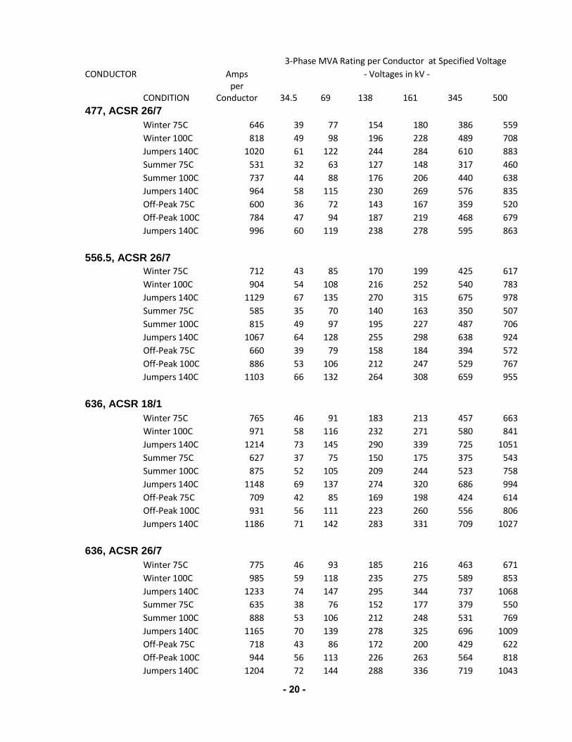
Conductor 34.5 69 138 161 345 500 477, ACSR 26/7 Winter 75C 646 39 77 154 180 386 559
Winter 100C 818 49 98 196 228 489 708
Jumpers 140C 1020 61 122 244 284 610 883
Summer 75C 531 32 63 127 148 317 460
Summer 100C 737 44 88 176 206 440 638
Jumpers 140C 964 58 115 230 269 576 835
Off-Peak 75C 600 36 72 143 167 359 520
Off-Peak 100C 784 47 94 187 219 468 679
Jumpers 140C 996 60 119 238 278 595 863
556.5, ACSR 26/7 Winter 75C 712 43 85 170 199 425 617
Winter 100C 904 54 108 216 252 540 783
Jumpers 140C 1129 67 135 270 315 675 978
Summer 75C 585 35 70 140 163 350 507
Summer 100C 815 49 97 195 227 487 706
Jumpers 140C 1067 64 128 255 298 638 924
Off-Peak 75C 660 39 79 158 184 394 572
Off-Peak 100C 886 53 106 212 247 529 767
Jumpers 140C 1103 66 132 264 308 659 955 636, ACSR 18/1 Winter 75C 765 46 91 183 213 457 663
Winter 100C 971 58 116 232 271 580 841
Jumpers 140C 1214 73 145 290 339 725 1051
Summer 75C 627 37 75 150 175 375 543
Summer 100C 875 52 105 209 244 523 758
Jumpers 140C 1148 69 137 274 320 686 994
Off-Peak 75C 709 42 85 169 198 424 614
Off-Peak 100C 931 56 111 223 260 556 806
Jumpers 140C 1186 71 142 283 331 709 1027 636, ACSR 26/7 Winter 75C 775 46 93 185 216 463 671
Winter 100C 985 59 118 235 275 589 853
Jumpers 140C 1233 74 147 295 344 737 1068
Summer 75C 635 38 76 152 177 379 550
Summer 100C 888 53 106 212 248 531 769
Jumpers 140C 1165 70 139 278 325 696 1009
Off-Peak 75C 718 43 86 172 200 429 622
Off-Peak 100C 944 56 113 226 263 564 818
Jumpers 140C 1204 72 144 288 336 719 1043
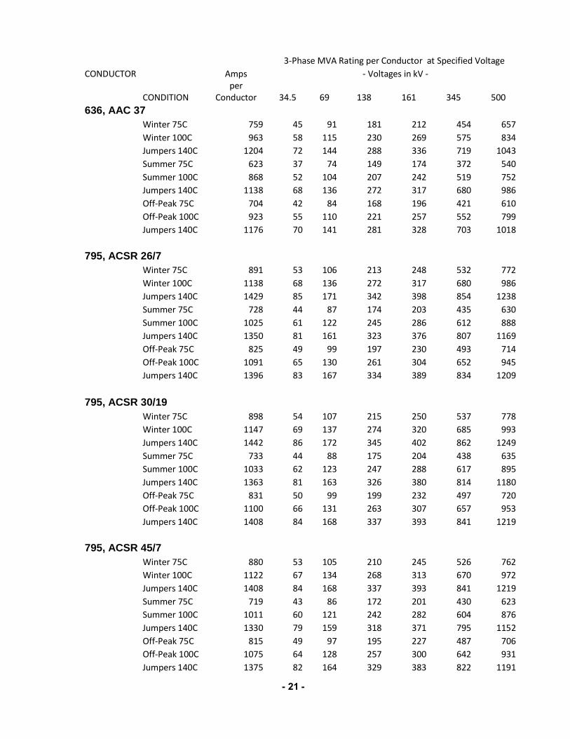
- 21 -
3-Phase MVA Rating per Conductor at Specified Voltage CONDUCTOR Amps - Voltages in kV -
CONDITION per
Conductor 34.5 69 138 161 345 500 636, AAC 37 Winter 75C 759 45 91 181 212 454 657
Winter 100C 963 58 115 230 269 575 834
Jumpers 140C 1204 72 144 288 336 719 1043
Summer 75C 623 37 74 149 174 372 540
Summer 100C 868 52 104 207 242 519 752
Jumpers 140C 1138 68 136 272 317 680 986
Off-Peak 75C 704 42 84 168 196 421 610
Off-Peak 100C 923 55 110 221 257 552 799
Jumpers 140C 1176 70 141 281 328 703 1018
795, ACSR 26/7 Winter 75C 891 53 106 213 248 532 772
Winter 100C 1138 68 136 272 317 680 986
Jumpers 140C 1429 85 171 342 398 854 1238
Summer 75C 728 44 87 174 203 435 630
Summer 100C 1025 61 122 245 286 612 888
Jumpers 140C 1350 81 161 323 376 807 1169
Off-Peak 75C 825 49 99 197 230 493 714
Off-Peak 100C 1091 65 130 261 304 652 945
Jumpers 140C 1396 83 167 334 389 834 1209 795, ACSR 30/19 Winter 75C 898 54 107 215 250 537 778
Winter 100C 1147 69 137 274 320 685 993
Jumpers 140C 1442 86 172 345 402 862 1249
Summer 75C 733 44 88 175 204 438 635
Summer 100C 1033 62 123 247 288 617 895
Jumpers 140C 1363 81 163 326 380 814 1180
Off-Peak 75C 831 50 99 199 232 497 720
Off-Peak 100C 1100 66 131 263 307 657 953
Jumpers 140C 1408 84 168 337 393 841 1219
795, ACSR 45/7 Winter 75C 880 53 105 210 245 526 762
Winter 100C 1122 67 134 268 313 670 972
Jumpers 140C 1408 84 168 337 393 841 1219
Summer 75C 719 43 86 172 201 430 623
Summer 100C 1011 60 121 242 282 604 876
Jumpers 140C 1330 79 159 318 371 795 1152
Off-Peak 75C 815 49 97 195 227 487 706
Off-Peak 100C 1075 64 128 257 300 642 931
Jumpers 140C 1375 82 164 329 383 822 1191
- 22 -
3-Phase MVA Rating per Conductor at Specified Voltage CONDUCTOR Amps - Voltages in kV -
CONDITION per
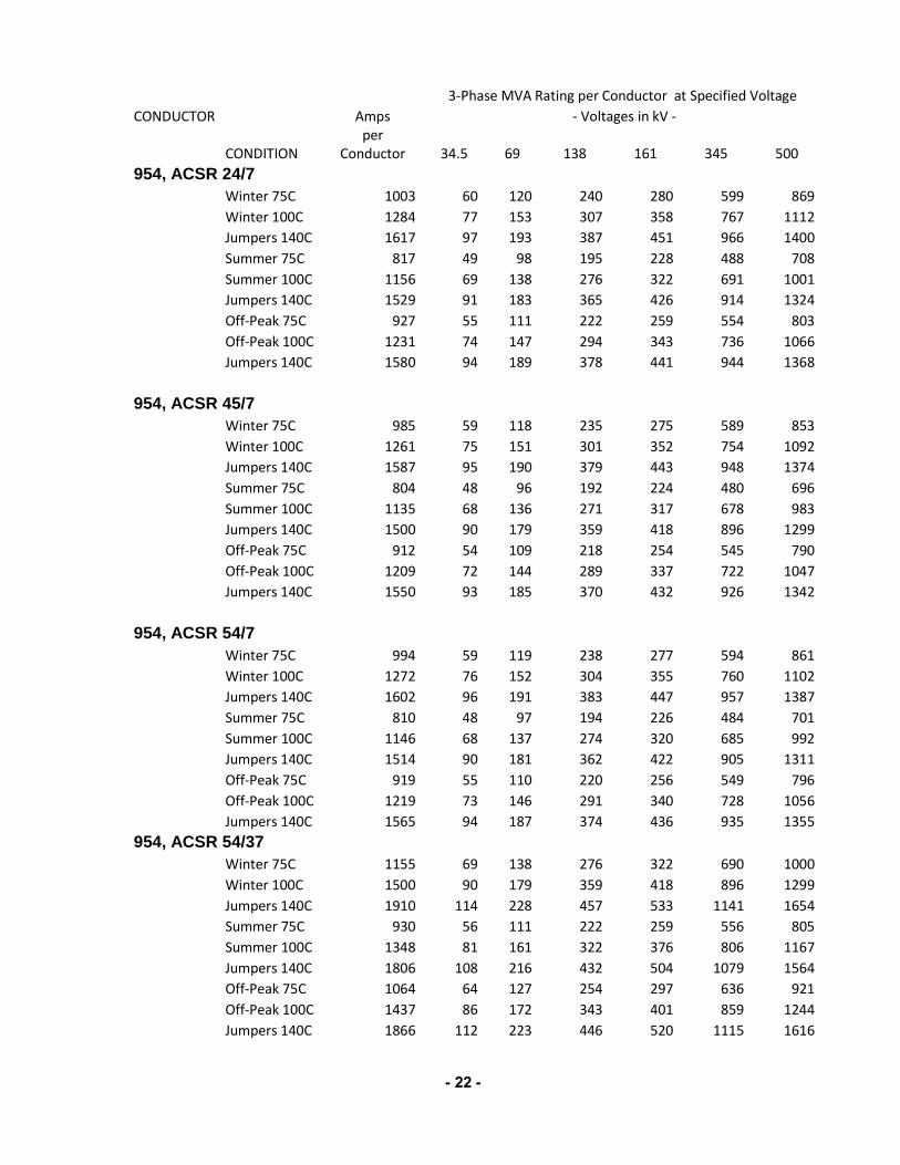
Conductor 34.5 69 138 161 345 500 954, ACSR 24/7 Winter 75C 1003 60 120 240 280 599 869
Winter 100C 1284 77 153 307 358 767 1112
Jumpers 140C 1617 97 193 387 451 966 1400
Summer 75C 817 49 98 195 228 488 708
Summer 100C 1156 69 138 276 322 691 1001
Jumpers 140C 1529 91 183 365 426 914 1324
Off-Peak 75C 927 55 111 222 259 554 803
Off-Peak 100C 1231 74 147 294 343 736 1066
Jumpers 140C 1580 94 189 378 441 944 1368
954, ACSR 45/7 Winter 75C 985 59 118 235 275 589 853
Winter 100C 1261 75 151 301 352 754 1092
Jumpers 140C 1587 95 190 379 443 948 1374
Summer 75C 804 48 96 192 224 480 696
Summer 100C 1135 68 136 271 317 678 983
Jumpers 140C 1500 90 179 359 418 896 1299
Off-Peak 75C 912 54 109 218 254 545 790
Off-Peak 100C 1209 72 144 289 337 722 1047
Jumpers 140C 1550 93 185 370 432 926 1342
954, ACSR 54/7 Winter 75C 994 59 119 238 277 594 861
Winter 100C 1272 76 152 304 355 760 1102
Jumpers 140C 1602 96 191 383 447 957 1387
Summer 75C 810 48 97 194 226 484 701
Summer 100C 1146 68 137 274 320 685 992
Jumpers 140C 1514 90 181 362 422 905 1311
Off-Peak 75C 919 55 110 220 256 549 796
Off-Peak 100C 1219 73 146 291 340 728 1056
Jumpers 140C 1565 94 187 374 436 935 1355 954, ACSR 54/37 Winter 75C 1155 69 138 276 322 690 1000
Winter 100C 1500 90 179 359 418 896 1299
Jumpers 140C 1910 114 228 457 533 1141 1654
Summer 75C 930 56 111 222 259 556 805
Summer 100C 1348 81 161 322 376 806 1167
Jumpers 140C 1806 108 216 432 504 1079 1564
Off-Peak 75C 1064 64 127 254 297 636 921
Off-Peak 100C 1437 86 172 343 401 859 1244
Jumpers 140C 1866 112 223 446 520 1115 1616

- 23 -
3-Phase MVA Rating per Conductor at Specified Voltage CONDUCTOR Amps - Voltages in kV -
CONDITION per
Conductor 34.5 69 138 161 345 500 954, AACSR/HS285 Winter 75C 961 57 115 230 268 574 832
Winter 100C 1238 74 148 296 345 740 1072
Jumpers 140C 1570 94 188 375 438 938 1360
Summer 75C 783 47 94 187 218 468 678
Summer 100C 1115 67 133 267 311 666 966
Jumpers 140C 1484 89 177 355 414 887 1285
Off-Peak 75C 889 53 106 212 248 531 770
Off-Peak 100C 1187 71 142 284 331 709 1028
Jumpers 140C 1533 92 183 366 427 916 1328
1192.5, ACSR 45/7 Winter 75C 1131 68 135 270 315 676 979
Winter 100C 1453 87 174 347 405 868 1258
Jumpers 140C 1836 110 219 439 512 1097 1590
Summer 75C 919 55 110 220 256 549 796
Summer 100C 1308 78 156 313 365 782 1133
Jumpers 140C 1736 104 207 415 484 1037 1503
Off-Peak 75C 1045 62 125 250 291 624 905
Off-Peak 100C 1393 83 166 333 388 832 1206
Jumpers 140C 1794 107 214 429 500 1072 1554
1192.5, ACSR 54/19 Winter 75C 1154 69 138 276 322 690 999
Winter 100C 1484 89 177 355 414 887 1285
Jumpers 140C 1875 112 224 448 523 1120 1624
Summer 75C 973 58 116 233 271 581 843
Summer 100C 1336 80 160 319 373 798 1157
Jumpers 140C 1773 106 212 424 494 1059 1535
Off-Peak 75C 1066 64 127 255 297 637 923
Off-Peak 100C 1422 85 170 340 397 850 1231
Jumpers 140C 1832 109 219 438 511 1095 1587 1222, ACCC/TW Winter 75C 1132 68 135 271 316 676 980
Winter 100C 1449 87 173 346 404 866 1255
Jumpers 140C 1826 109 218 436 509 1091 1581
Summer 75C 922 55 110 220 257 551 798
Summer 100C 1305 78 156 312 364 780 1130
Jumpers 140C 1726 103 206 413 481 1031 1495
Off-Peak 75C 1047 63 125 250 292 626 907
Off-Peak 100C 1389 83 166 332 387 830 1203
Jumpers 140C 1783 107 213 426 497 1065 1544

- 24 -
3-Phase MVA Rating per Conductor at Specified Voltage CONDUCTOR Amps - Voltages in kV -
CONDITION per
Conductor 34.5 69 138 161 345 500 1272, ACSR 45/7 Winter 75C 1176 70 141 281 328 703 1018
Winter 100C 1514 90 181 362 422 905 1311
Jumpers 140C 1915 114 229 458 534 1144 1658
Summer 75C 955 57 114 228 266 571 827
Summer 100C 1362 81 163 326 380 814 1180
Jumpers 140C 1810 108 216 433 505 1082 1568
Off-Peak 75C 1086 65 130 260 303 649 941
Off-Peak 100C 1450 87 173 347 404 866 1256
Jumpers 140C 1870 112 223 447 521 1117 1619
1351.5, ACSS/TW 36/37 Winter 75C 1342 80 160 321 374 802 1162
Winter 100C 1735 104 207 415 484 1037 1503
Jumpers 140C 2200 131 263 526 613 1315 1905
Summer 75C 1084 65 130 259 302 648 939
Summer 100C 1560 93 186 373 435 932 1351
Jumpers 140C 2080 124 249 497 580 1243 1801
Off-Peak 75C 1237 74 148 296 345 739 1071
Off-Peak 100C 1662 99 199 397 463 993 1439
Jumpers 140C 2149 128 257 514 599 1284 1861 1431, ACSR 45/7 Winter 75C 1263 75 151 302 352 755 1094
Winter 100C 1631 97 195 390 455 975 1412
Jumpers 140C 2068 124 247 494 577 1236 1791
Summer 75C 1024 61 122 245 286 612 887
Summer 100C 1467 88 175 351 409 877 1270
Jumpers 140C 1955 117 234 467 545 1168 1693
Off-Peak 75C 1166 70 139 279 325 697 1010
Off-Peak 100C 1562 93 187 373 436 933 1353
Jumpers 140C 2020 121 241 483 563 1207 1749 1533.3, ACSS/TW 39/19 Winter 75C 1323 79 158 316 369 791 1146
Winter 100C 1705 102 204 408 475 1019 1477
Jumpers 140C 2158 129 258 516 602 1290 1869
Summer 75C 1074 64 128 257 299 642 930
Summer 100C 1534 92 183 367 428 917 1328
Jumpers 140C 2040 122 244 488 569 1219 1767
Off-Peak 75C 1222 73 146 292 341 730 1058
Off-Peak 100C 1633 98 195 390 455 976 1414
Jumpers 140C 2108 126 252 504 588 1260 1826
- 25 -
3-Phase MVA Rating per Conductor at Specified Voltage CONDUCTOR Amps - Voltages in kV -
CONDITION per
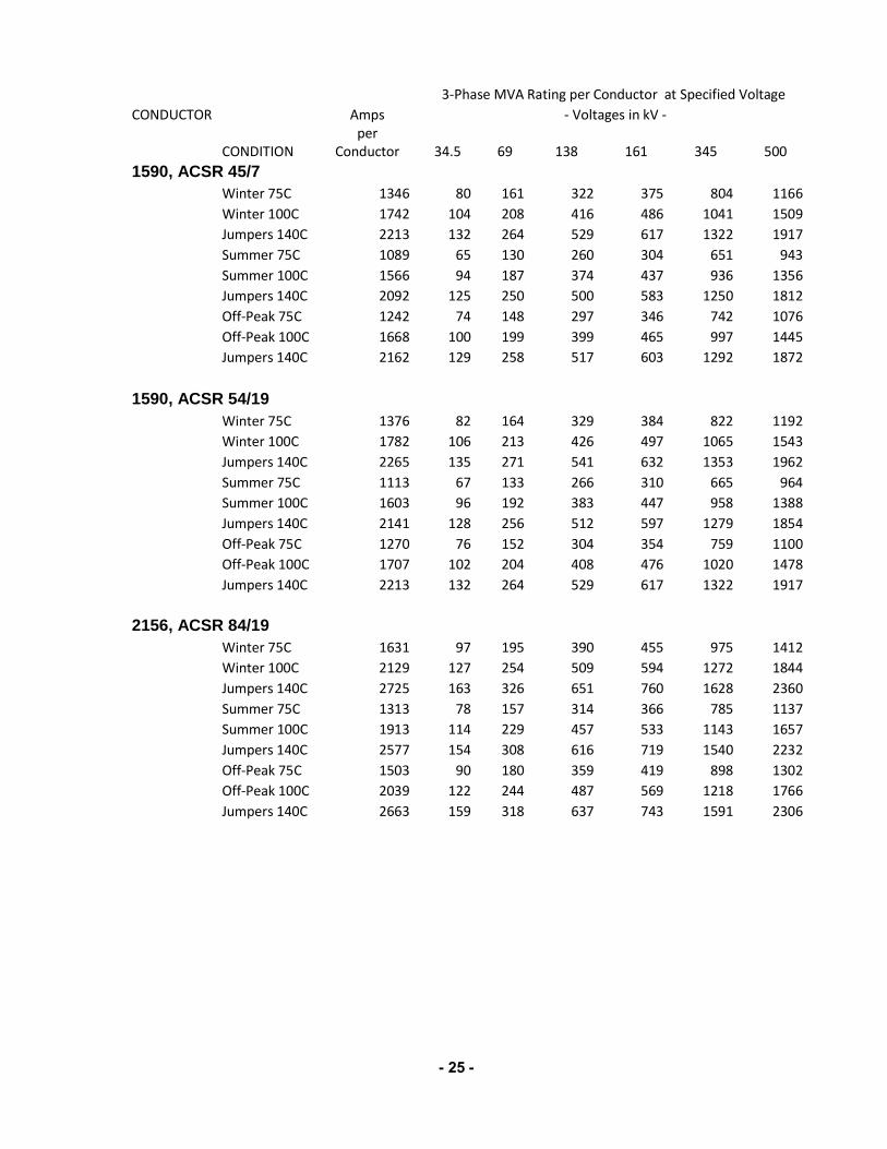
Conductor 34.5 69 138 161 345 500 1590, ACSR 45/7 Winter 75C 1346 80 161 322 375 804 1166
Winter 100C 1742 104 208 416 486 1041 1509
Jumpers 140C 2213 132 264 529 617 1322 1917
Summer 75C 1089 65 130 260 304 651 943
Summer 100C 1566 94 187 374 437 936 1356
Jumpers 140C 2092 125 250 500 583 1250 1812
Off-Peak 75C 1242 74 148 297 346 742 1076
Off-Peak 100C 1668 100 199 399 465 997 1445
Jumpers 140C 2162 129 258 517 603 1292 1872 1590, ACSR 54/19 Winter 75C 1376 82 164 329 384 822 1192
Winter 100C 1782 106 213 426 497 1065 1543
Jumpers 140C 2265 135 271 541 632 1353 1962
Summer 75C 1113 67 133 266 310 665 964
Summer 100C 1603 96 192 383 447 958 1388
Jumpers 140C 2141 128 256 512 597 1279 1854
Off-Peak 75C 1270 76 152 304 354 759 1100
Off-Peak 100C 1707 102 204 408 476 1020 1478
Jumpers 140C 2213 132 264 529 617 1322 1917
2156, ACSR 84/19 Winter 75C 1631 97 195 390 455 975 1412
Winter 100C 2129 127 254 509 594 1272 1844
Jumpers 140C 2725 163 326 651 760 1628 2360
Summer 75C 1313 78 157 314 366 785 1137
Summer 100C 1913 114 229 457 533 1143 1657
Jumpers 140C 2577 154 308 616 719 1540 2232
Off-Peak 75C 1503 90 180 359 419 898 1302
Off-Peak 100C 2039 122 244 487 569 1218 1766
Jumpers 140C 2663 159 318 637 743 1591 2306

- 26 -
Assumptions Summer Ambient Temp = 100 F Winter Ambient Temp = 77 F Off-Peak Ambient Temp = 87 F Wind Speed = 2 ft/sec Coef of Emiss = 0.85 Coef of Absorp = 0.90 Latitude = 38 deg 12 pm Local Sun Time 75 C/100 C Line Design Temps Elevation = 1000 ft Clear Atmosphere
- 27 -
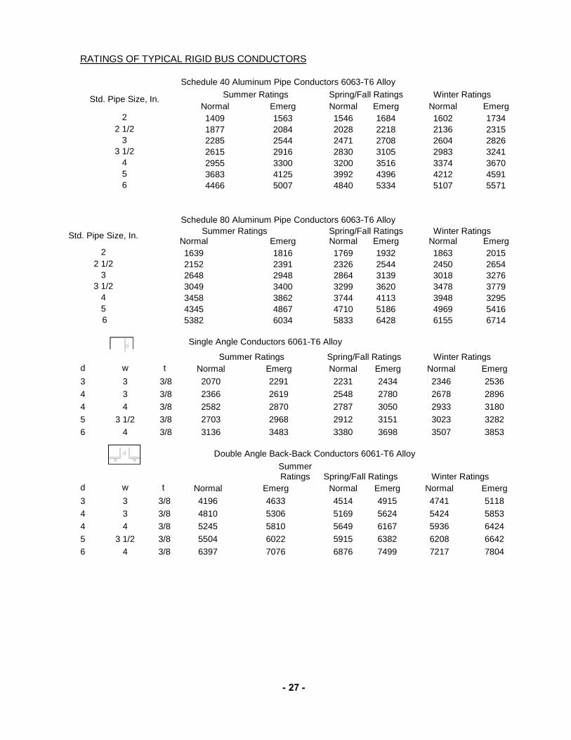
RATINGS OF TYPICAL RIGID BUS CONDUCTORS
Schedule 40 Aluminum Pipe Conductors 6063-T6 Alloy
Std. Pipe Size, In. Summer Ratings Spring/Fall Ratings Winter Ratings Normal Emerg Normal Emerg Normal Emerg
2 1409 1563 1546 1684 1602 1734 2 1/2 1877 2084 2028 2218 2136 2315
3 2285 2544 2471 2708 2604 2826 3 1/2 2615 2916 2830 3105 2983 3241
4 2955 3300 3200 3516 3374 3670 5 3683 4125 3992 4396 4212 4591 6 4466 5007 4840 5334 5107 5571
Schedule 80 Aluminum Pipe Conductors 6063-T6 Alloy
Std. Pipe Size, In. Summer Ratings Spring/Fall Ratings Winter Ratings Normal Emerg Normal Emerg Normal Emerg
2 1639 1816 1769 1932 1863 2015 2 1/2 2152 2391 2326 2544 2450 2654
3 2648 2948 2864 3139 3018 3276 3 1/2 3049 3400 3299 3620 3478 3779
4 3458 3862 3744 4113 3948 3295 5 4345 4867 4710 5186 4969 5416 6 5382 6034 5833 6428 6155 6714
Single Angle Conductors 6061-T6 Alloy Summer Ratings Spring/Fall Ratings Winter Ratings d w t Normal Emerg Normal Emerg Normal Emerg 3 3 3/8 2070 2291 2231 2434 2346 2536 4 3 3/8 2366 2619 2548 2780 2678 2896 4 4 3/8 2582 2870 2787 3050 2933 3180 5 3 1/2 3/8 2703 2968 2912 3151 3023 3282 6 4 3/8 3136 3483 3380 3698 3507 3853
Double Angle Back-Back Conductors 6061-T6 Alloy
Summer Ratings Spring/Fall Ratings Winter Ratings
d w t Normal Emerg Normal Emerg Normal Emerg 3 3 3/8 4196 4633 4514 4915 4741 5118 4 3 3/8 4810 5306 5169 5624 5424 5853 4 4 3/8 5245 5810 5649 6167 5936 6424 5 3 1/2 3/8 5504 6022 5915 6382 6208 6642 6 4 3/8 6397 7076 6876 7499 7217 7804
- 28 -
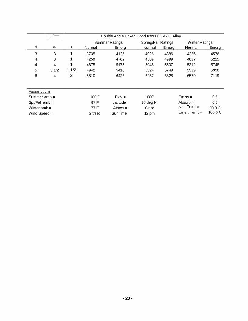
Double Angle Boxed Conductors 6061-T6 Alloy Summer Ratings Spring/Fall Ratings Winter Ratings d w s Normal Emerg Normal Emerg Normal Emerg 3 3 1 3735 4125 4026 4386 4236 4576 4 3 1 4259 4702 4589 4999 4827 5215 4 4 1 4675 5175 5045 5507 5312 5748 5 3 1/2 1 1/2 4942 5410 5324 5749 5599 5996 6 4 2 5810 6426 6257 6828 6579 7119
Assumptions Summer amb.= 100 F Elev.= 1000' Emiss.= 0.5 Spr/Fall amb.= 87 F Latitude= 38 deg N. Absorb.= 0.5 Winter amb.= 77 F Atmos.= Clear Nor. Temp= 90.0 C Wind Speed = 2ft/sec Sun time= 12 pm Emer. Temp= 100.0 C
- 29
-
App
endi
x B
:
79
5 m
cm A
CS
R C
ondu
ctor
Tabl
e B
1 - E
leva
tion
Sen
sitiv
ity A
naly
sis
Res
ults
Win
ter
Am
ps
Nor
m/E
mer
Sum
mer
Am
ps
Nor
m/E
mer
Loca
l Sun
tim
e =
12pm
0 89
9/11
46
735/
1032
Latit
ude
= 38
Deg
500
892/
1140
72
8/10
26
Ea
st -
Wes
t lin
e di
rect
ion
100
0 88
5/11
34
721/
1020
1
500
879/
1127
71
4/10
14
200
0 87
2/11
21
707/
1008
Tabl
e B
2 - L
atitu
de, D
irect
ion
and
Loca
l Sun
Tim
e S
ensi
tivity
Ana
lysi
s R
esul
ts
W
inte
r Am
ps
S
umm
er A
mps
Latit
ude
(deg
rees
)
Latit
ude
(deg
rees
)
37
Nor
m/E
me
r
38
Nor
m/E
mer
39
Nor
m/E
me
r
40
Nor
m/E
mer
37
N
orm
/Em
er
38
Nor
m/E
me
r
39
Nor
m/E
me
r
40
Nor
m/E
me
r El
evat
ion
= 10
00ft
10
90
8/11
50
908/
1150
90
8/11
50
908/
1150
748/
1038
74
8/10
38
748/
1038
74
8/10
38
Eas
t - W
est l
ine
dire
ctio
n
11
891/
1137
89
1/11
37
891/
1138
89
1/11
38
72
7/10
24
727/
1024
72
8/10
25
728/
1025
12
88
5/11
33
885/
1134
88
6/11
34
886/
1134
721/
1020
72
1/10
20
721/
1020
72
1/10
20
1 89
1/11
37
891/
1137
89
1/11
38
891/
1138
727/
1024
72
7/10
24
728/
1025
72
8/10
25
2 90
8/11
50
908/
1150
90
8/11
50
908/
1150
748/
1038
74
8/10
38
748/
1038
74
9/10
38
W
inte
r Am
ps
S
umm
er A
mps
Latit
ude
(deg
rees
)
Latit
ude
(deg
rees
)
37
Nor
m/E
me
r
38
Nor
m/E
me
r
39
Nor
m/E
me
r
40
Nor
m/E
mer
g 37
N
orm
/Em
er
38
Nor
m/E
me
r
39
Nor
m/E
me
r
40
Nor
m/E
me
r El
evat
ion
= 10
00ft
10
89
2/11
38
892/
1139
89
3/11
39
894/
1140
729/
1025
72
9/10
26
730/
1026
73
1/10
27
Nor
th-S
outh
line
dire
ctio
n
11
895/
1140
89
6/11
41
896/
1141
89
7/11
42
73
2/10
28
733/
1028
73
4/10
29
735/
1030
12
89
1/11
37
891/
1138
89
2/11
38
893/
1139
727/
1024
72
8/10
25
729/
1026
73
0/10
26
1 89
5/11
40
896/
1141
89
6/11
41
897/
1142
732/
1028
73
3/10
28
734/
1029
73
5/10
30
2 89
2/11
38
892/
1139
89
3/11
39
894/
1139
729/
1025
72
9/10
26
730/
1026
73
1/10
27
Sum
mer
Am
bien
t Tem
p =
100
F E
mer
g co
nd te
mp
=100
C
Win
ter A
mbi
ent T
emp
= 77
F
Cle
ar A
tmos
pher
e
Win
d sp
eed
= 2
ft/s
C
oef o
f Sol
ar A
bsor
ptio
n =
0.9
Nor
m c
ond
tem
p =
75 C
Coe
f of I
nfra
red
Emis
sivi
ty =
0.8
5

- 30 -
Appendix C: Maximum Temperatures
Calculated Maximum Summer Ambient Temperatures (June through September)
Year Columbia Kansas City Springfield St. Louis 1991 97.7 99.8 97.4 98.9 1992 91.2 89.8 89.9 94.2 1993 93.0 95.2 94.8 94.8 1994 94.1 94.0 94.1 95.1 1995 95.4 96.1 97.0 97.4
Maximum 97.7 99.8 97.4 98.9
Calculated Maximum Winter Ambient Temperatures (December through March)
Year Columbia Kansas City Springfield St. Louis 1991 77.9 75.9 74.9 80.7 1992 74.7 73.1 73.1 74.6 1993 71.5 65.6 72.5 70.1 1994 74.9 75.0 75.1 75.3 1995 75.9 76.3 78.7 76.2
Maximum 77.9 76.3 78.7 80.7
Calculated Maximum Off-Peak Ambient Temperatures (April, May, October and November)
Year Columbia Kansas City Springfield St. Louis 1991 86.8 85.6 84.6 90.1 1992 83.1 83.0 82.1 84.8 1993 82.0 82.0 81.0 83.8 1994 83.6 86.1 84.4 85.3 1995 83.1 82.7 84.1 84.5
Maximum 86.8 86.1 84.6 90.1
- 31
-
Appe
ndix
D: W
avet
rap
Load
abili
ty F
acto
r vs
Am
bien
t Tem
pera
ture
0.951
1.051.1
1.151.2
1.251.3
1.351.4
-10
010
2030
4050
6070
8090
100
Load Factor
Deg
rees
Fah
renh
eit
Nor
mal
Loa
dabi
lity
Fact
or -
Air C
ore
4-H
our E
mer
genc
y Lo
adab
ility
Fac
tor -
Air
Cor
eN
orm
al L
oada
bilit
y Fa
ctor
- E
poxy

- 32 -
Appendix E: Short Term Loading Guidelines
Short Term Loading Times for Common AECI Conductors SEASONAL -- 70% PRECONTINGENCY LOADING FOLLOWED BY 120% POST CONTINGENCY LOADING
Conductor Name MCM Type Stranding
Time in minutes to reach max. conductor temperature
Summer Spring/Fall Winter Falcon 1590 ACSR 54/19 12.8 13.1 13.4 Lapwing 1590 ACSR 45/7 12.1 12.4 12.6 Rio Grande 1533.3 ACSS/TW 39/19 17.9 12.1 12.4 River Cross 1351.5 ACSS/TW 36/37 18.5 18.8 19.2
Grackle 1192.5 ACSR 54/19 10.6 11.0 11.2 Cardinal 954 ACSR 54/7 9.2 9.5 9.7 Drake 795 ACSR 26/7 8.4 8.6 8.8 Grosbeak 636 ACSR 26/7 7.2 7.4 7.6 Dove 556.5 ACSR 26/7 6.6 6.8 6.9 Hawk 477 ACSR 26/7 6.0 6.1 6.2
AECI Short Term Load Guide for Disconnect Switches
SEASONAL
AECI Seasons
For most limiting case
Max Switch
Part Temp
Max Switch
Part Temp Rise
Avail Switch
Part Temp Rise
Max Ambient Temp
Continuous Rating Factors
15 Minute Rating
Factors2 Summer 70 30 15.3 40 100% 152% Spring/Fall 70 30 15.3 30 115% 152% Winter 70 30 15.3 25 122% 167%
AECI Short Term Load Guide for Power Circuit Breakers SEASONAL -- 70% PRECONTINGENCY LOADING
AECI Seasons
For most limiting case 70% Initial
Limit Break Part
Temp
Limit Break Part
Temp Rise
Avail Break Part Temp Rise
Max Ambient Temp
Continuous Rating Factors
15 Minute Rating
Factors2 Summer 150 110 52.1 40 100% 148% Spring/Fall 150 110 52.1 30 104% 151% Winter 150 110 52.1 25 107% 153%
- 33 -
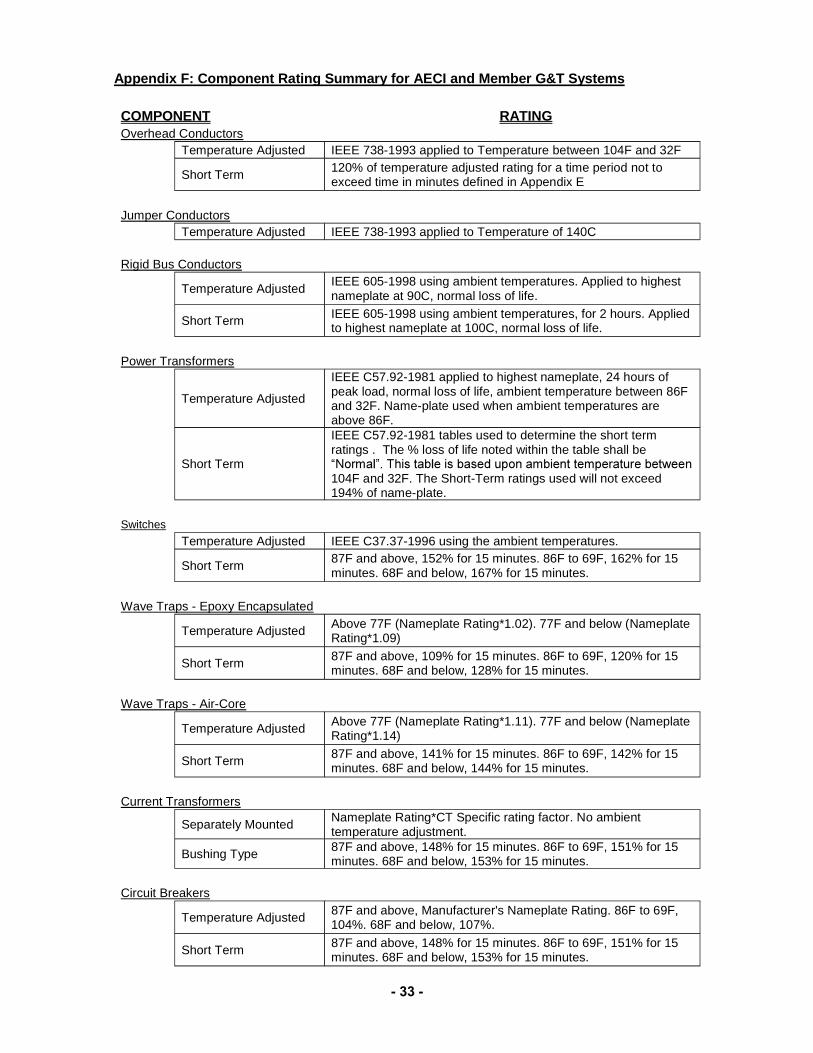
Appendix F: Component Rating Summary for AECI and Member G&T Systems
COMPONENT RATING Overhead Conductors Temperature Adjusted IEEE 738-1993 applied to Temperature between 104F and 32F Short Term 120% of temperature adjusted rating for a time period not to
exceed time in minutes defined in Appendix E Jumper Conductors Temperature Adjusted IEEE 738-1993 applied to Temperature of 140C Rigid Bus Conductors Temperature Adjusted IEEE 605-1998 using ambient temperatures. Applied to highest
nameplate at 90C, normal loss of life. Short Term IEEE 605-1998 using ambient temperatures, for 2 hours. Applied
to highest nameplate at 100C, normal loss of life. Power Transformers
Temperature Adjusted
IEEE C57.92-1981 applied to highest nameplate, 24 hours of peak load, normal loss of life, ambient temperature between 86F and 32F. Name-plate used when ambient temperatures are above 86F.
Short Term
IEEE C57.92-1981 tables used to determine the short term ratings . The % loss of life noted within the table shall be
104F and 32F. The Short-Term ratings used will not exceed 194% of name-plate.
Switches Temperature Adjusted IEEE C37.37-1996 using the ambient temperatures. Short Term 87F and above, 152% for 15 minutes. 86F to 69F, 162% for 15
minutes. 68F and below, 167% for 15 minutes. Wave Traps - Epoxy Encapsulated
Temperature Adjusted Above 77F (Nameplate Rating*1.02). 77F and below (Nameplate Rating*1.09)
Short Term 87F and above, 109% for 15 minutes. 86F to 69F, 120% for 15 minutes. 68F and below, 128% for 15 minutes.
Wave Traps - Air-Core
Temperature Adjusted Above 77F (Nameplate Rating*1.11). 77F and below (Nameplate Rating*1.14)
Short Term 87F and above, 141% for 15 minutes. 86F to 69F, 142% for 15 minutes. 68F and below, 144% for 15 minutes.
Current Transformers
Separately Mounted Nameplate Rating*CT Specific rating factor. No ambient temperature adjustment.
Bushing Type 87F and above, 148% for 15 minutes. 86F to 69F, 151% for 15 minutes. 68F and below, 153% for 15 minutes.
Circuit Breakers
Temperature Adjusted 87F and above, Manufacturer's Nameplate Rating. 86F to 69F, 104%. 68F and below, 107%.
Short Term 87F and above, 148% for 15 minutes. 86F to 69F, 151% for 15 minutes. 68F and below, 153% for 15 minutes.
- 34 -
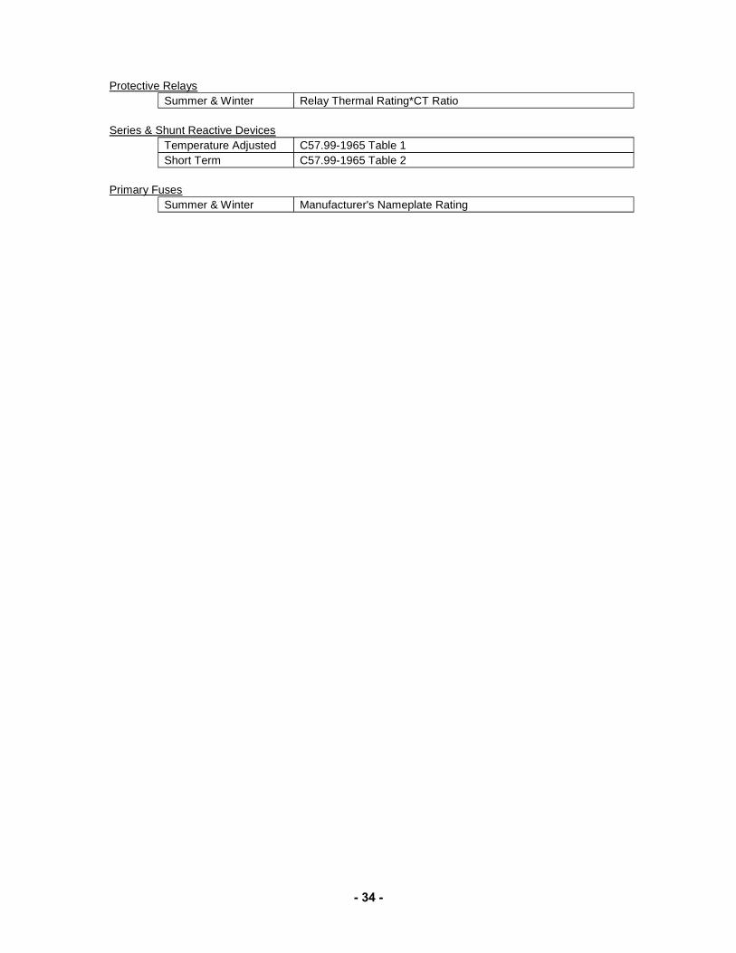
Protective Relays Summer & Winter Relay Thermal Rating*CT Ratio Series & Shunt Reactive Devices Temperature Adjusted C57.99-1965 Table 1 Short Term C57.99-1965 Table 2 Primary Fuses Summer & Winter Manufacturer's Nameplate Rating