notes - artisan technology group · 4 basic battery service 17 servicing batteries with bar code...
TRANSCRIPT

C7000 & C7000ER Battery AnalyzerUser’s Manual
DisclaimerWhile every effort is made to ensure that the information contained in this manual is accurateand up-to-date, Cadex Electronics Inc. does not warrant or guarantee the accuracy of thecontents of this manual. Further, Cadex makes no warranties, either expressed or implied, as tothe merchantability or fitness for a particular purpose of the C7000 and C7000ER BatteryAnalyzer equipment and/or its documentation.
In no event will Cadex or its officers or employees be responsible for any consequential,incidental, or indirect damages (including damages for loss of business profits, businessinterruption, and the like) arising out of the use or inability to use the C7000 and C7000ERBattery Analyzer equipment and/or its documentation.
Year 2000 ComplianceAll functions and performance of the Cadex C7000 and C7000ER Battery Analyzers areindependent of the date stored in the analyzer. Therefore, all functions and the performance ofthe C7000 and C7000ER Battery Analyzers are not affected by dates during and after the year2000.
Cadex Electronics Inc.22000 Fraserwood WayRichmond, British ColumbiaCanada V6W 1J6Tel: +1 604 231-7777 Fax: +1 604 231-7755Web: www.cadex.com Email: [email protected]
CopyrightCopyright © 2000 by Cadex Electronics Inc. All rights reserved. No part of this publication or thefirmware controlling Cadex product(s) may be reproduced, transmitted, transcribed, stored in aretrieval system, or translated into any language or computer language in any form or by anymeans without the express written permission of Cadex Electronics Inc.
Cadex Electronics Inc. reserves the right to revise this publication and make changes in itscontents without obligation to notify any person of such changes.
TrademarkCADEX is a registered trademark of Cadex Electronics Inc. All other trademarks mentionedherein are the property of their respective owners.
89-207-1001 Rev 8 March, 2000 Printed in Canadai
Notes

ii C7000 & 7000ER Battery Analyzer V3.5
1 Overview 1Product Features ............................................................................................ 1What’s New in the C7000 V3.5 firmware ........................................................ 2Firmware Upgrade: Resetting the System ...................................................... 3Connecting to BatteryShop™ ......................................................................... 3Peripherals ...................................................................................................... 4
2 Getting Started 5Contents of Box .............................................................................................. 5About this Manual ........................................................................................... 5Conventions .................................................................................................... 5Symbols .......................................................................................................... 6Abbreviations and Acronyms .......................................................................... 6Commonly Used Terms ................................................................................... 7
3 Operating Principles 8Components ................................................................................................... 8Option Boards ................................................................................................. 9
Components ............................................................................................... 9Battery Adapters ........................................................................................... 10
Special Handling Tip for Smart Cable Adapters ....................................... 11User Interface ............................................................................................... 12
Display ...................................................................................................... 12Menu ......................................................................................................... 14Commands ............................................................................................... 15Function Keys ........................................................................................... 15Lights (LEDs) ............................................................................................ 16
4 Basic Battery Service 17Servicing Batteries with Bar Code ................................................................ 20
5 Battery Service Programs 21Basic Programs ............................................................................................ 21Specialty Programs ...................................................................................... 22Target Capacity ............................................................................................. 23Selecting a Program or Setting Target Capacity ........................................... 24Editing Program Settings .............................................................................. 25Duration of Service ....................................................................................... 26
Notes

iii
Contents
6 Battery Configuration/C-Codes 27Basic C-Code ................................................................................................ 27Extended C-Code ......................................................................................... 28Viewing C-Codes .......................................................................................... 30Managing C-Codes ....................................................................................... 30
Selecting Correct Voltage ......................................................................... 31Intrinsically Safe Settings ......................................................................... 31Default Settings for Extended C-Codes .................................................... 32
7 Custom Programs 33Cycle 1 and Cycle 2 ...................................................................................... 34Test ............................................................................................................... 35True and False Statements ........................................................................... 37Phase Done .................................................................................................. 38Example ........................................................................................................ 38Creating or Modifying a Custom Program..................................................... 40
8 System Security 41Password Requirement ................................................................................. 41Setting Security ............................................................................................. 42Changing Password and Removing Security ................................................ 42
9 System Setup 43Setting Up System Information ..................................................................... 44Calibration Procedures ................................................................................. 44
Calibrating Voltage .................................................................................... 44Calibrating Station .................................................................................... 45
Output Devices ............................................................................................. 46Serial Port Settings ................................................................................... 46Serial and Parallel Port Device Settings ................................................... 47
10 Print Utilities 48Printing Report or Label ................................................................................ 49
11 Event Log 50Log Events .................................................................................................... 51Managing Event Log ..................................................................................... 51
Notes

iv C7000 & 7000ER Battery Analyzer V3.5
12 Messages and Warnings 52By Detail ....................................................................................................... 53By Code ........................................................................................................ 63
13 Services and Upgrades 66Replacing the Primary (Input) Fuse .............................................................. 67
Standard Model (C7000-1, C7000-2, C7000-9) ........................................ 67Extended Range Model (C7000ER) ......................................................... 68
Replacing the Station Fuses ......................................................................... 69Standard Model (C7000-1, C7000-2, C7000-9) ........................................ 69Extended Range Model (C7000ER) ......................................................... 70
Replacing Backup Battery (with OP-70 or OP-72 only) ................................ 71IEC320 Power Cord ...................................................................................... 72
14 Specifications 73Hardware ...................................................................................................... 73Firmware ....................................................................................................... 74
15 Getting Help/Problem Solving 75Troubleshooting ............................................................................................. 75Manual Updates and Other References ....................................................... 78Technical Support ......................................................................................... 78
16 Safety Notice and Warranty 80Radio Interference ........................................................................................ 80Explosion Hazard .......................................................................................... 81Shock Hazard ............................................................................................... 82Warranty & Services ..................................................................................... 83
Obtaining Warranty Service ...................................................................... 83Non-warranty Repairs ............................................................................... 83
Index 84
Index
OOP-70, 9OP-72, 4, 9, 20option boards, 9, 71
Pparallel ports, 11, 47
device settings, 47password requirement, 41passwords, changing, 42peripherals, 4primary fuses, replacing, 67, 68print utilities, 48programs
Basic Programs, 21selecting, 18, 24Specialty Programs, 22
program settings, editing, 25
Rrecondition, 7, 21reports, 1, 4, 48
printing, 15, 49Residual Capacity, 7, 22
Ssafety notice, 81security, 41
removing, 42setting, 42
serial cable pin configurations, 46–47serial ports, 11, 46
device settings, 47settings, 46
service duration, 26service procedures, 17-19
batteries with bar code, 20
services and upgrades, 66Smart Batteries, 1, 7
storage of, 21, 22specifications, 73-74station fuses, replacing, 69, 70system, resetting, 3system information, setting up, 44system setup, 43
TTarget Capacity, 7, 23
setting, 19, 24Technical Support, 78troubleshooting, 75
Uupgrade to firmware V3.5, 3upgrades. See services and upgrades
Wwarnings, 52
by code, 63–65by detail, 53–63
warranty, 83–84
85

The Cadex C7000 and C7000ER Battery Analyzers are sophisticated
programmable battery analyzers capable of servicing batteries with different
electrical properties and mechanical dimensions.
Product Features
• Service Nickel Cadmium (NiCd), Nickel-Metal Hydride (NiMH), Sealed Lead
Acid (SLA) and Lithium Ion (Li-Ion). The C7000 and C7000ER are also
capable of supporting Smart Batteries based on the ‘single wire’ and SMBus
system.
• Operate each station simultaneously and independently of each other.
• Support over 600 interchangeable Battery Adapters for easy interface with
most commercially available battery models.
• The Battery Adapter contains the battery configuration code, also known as
C-Code, which automatically sets the analyzer to the correct parameters for
serving the battery. Each adapter contains 10 C-Codes to accommodate
different batteries in the same product family.
• Offer a variety of programs for battery services: 3 Basic Programs (Auto,
Charge, Prime), 6 Specialty Programs and 4 user-programmable Custom
Programs.
• Easy to use menu-driven interface, plain English messages and status lights.
• Support fleet management. Support bar code entry, print Bar Code Labels
and Battery Labels, and produce a range of reports.
• Can be networked for automated battery maintenance with BatteryShop™.
1
1
Overview1
Aabbreviations and acronyms, 6adapters. See Battery AdaptersAdapters, Voltage Calibration, 44Auto-Print, 48, 49
Bbackup battery, replacing, 71–72bar code scanner, 4bar codes, 1, 20Battery Adapters, 10, 27
Custom Adapters, 10Dual-station Adapters, 10inserting, 17removing, 18Smart Cable Adapters (Universal
Adapters), 3, 10, 11, 18, 27battery configuration codes. See C-
CodesBattery ID, 20, 48BatteryShop, 1, 3, 9, 33
CC-Codes, 1, 11, 27
active, 17, 20, 48Basic, 27Extended, 27, 28, 32managing, 30viewing, 17, 30
calibrations, 15, 44-45commands, 15commonly used terms, 7components, 8Custom Programs, 33
creating or modifying, 40
Ddisplay, 12, 13
EEvent Log, 50
log events, 51managing, 51
Ffeatures, 1firmware upgrade, 2, 3firmware version, viewing, 15function keys, 15fuses. See primary fuses, replacing;
station fuses, replacing
IIEC320 Power Cord, 5, 72internal resistance, 22
threshold, 22, 25intrinsically safe (I/S), 7
settings, 31
Kkeys, functions of, 8
Llabels, 1, 4, 48
printing, 15, 49LCD. See displayLEDs. See lightsLi-Ion, 6, 10, 27lights, 16
Mmemory, 7, 21menu, 14messages, 52
by code, 63–65by detail, 53–62
84 C7000 & 7000ER Battery Analyzer V3.5
What’s New in the C7000 V3.5 firmware
At Cadex, it is our goal to continue to listen to feedback and suggestions from
customers, and improve our products. Below is a list of product enhancements:
2 C7000 & 7000ER Battery Analyzer V3.5
Warranty & Services
Cadex Electronics Inc. warrants the Cadex C7000 and C7000ER Battery
Analyzers against defective materials and workmanship for a period of two (2)
years from the original purchase date.
The warranty does not cover
• Any damage due to abusive operation, negligence, accident or improper
installation.
• Any damage caused by an attempted repair not authorized by Cadex.
• Cosmetic damage caused by normal wear and tear.
• External causes of damage such as leakage spills, power fluctuations or
failure, or shipping.
• Product received without the appropriate model number, serial number or
safety markings.
• Product used for rental purposes.
Obtaining Warranty Service
1. Contact Cadex Technical Support. If the service representative has
determined that your product needs to be returned for service or
replacement, the representative will fax or provide a Return Authorization
number with the location of the nearest service center.
2. Ship the product to the service center with freight, insurance and customs
duties prepaid. Include the Return Authorization number provided by Cadex
or the service center. All products must be returned with a Return
Authorization number supplied by Cadex or a Cadex service center.
Products returned from warranty service will be sent with freight prepaid by
Cadex.
Non-warranty Repairs
Cadex will provide an estimate and will proceed with the repairs only after you
have provided a written authorization or a Purchase Order number. You will also
need a Return Authorization number.
Safety Notice and Warranty 16
83
Version New Features/Changes
3.5 Runtime programSupport for BatteryShop 3.0Definable Resistance Threshold in OhmTestRecognition of 16Kb Battery AdaptersImproved NiMH charge algorithmReorganized programs, separated Basic and Specialty Programs4 additional Custom ProgramsImproved user interface
3.4 Support for BatteryShopGeneral updates
3.3 Improved OhmTestIncorporation of OhmTest into the Auto, Prime and Charge programsAutomatic identification of battery parameters through Battery Adapters
3.2 OhmTest to test battery internal resistance in 5 secondsSupport for label printerTemperature sensor to improve safetyDisplay of battery model numbersImproved NiMH charge algorithmImproved bar code

Firmware Upgrade: Resetting the System
If you are upgrading the analyzer firmware to V3.5 from an older version, you
need to reset the system to the factory defaults to erase the old system
parameters.
Some of the parameters that are reset include:
• OhmTest, Runtime, Self-Discharge, Life-Cycling and Custom Programs
• Battery Startup settings
• Parallel Port Device to Printer
• Serial Port Device to LabelMaker
• Voltage Display to Volts/Cell
• Number of batteries serviced (Service Counter) to 0
! Press and release the Alt key, then press 0.
Note that this function also serves as a general system reboot.
Connecting to BatteryShop™
BatteryShop™ is a powerful Windows-based battery management tool that
allows automation of the C7000 and C7000ER functions to increase
productivity.
• Provides control and monitoring of large scale battery services by
connecting up to 120 analyzers to service 480 batteries simultaneously.
• Contains a database of over 2000 battery models that provides easy
access to C-Code settings and other information. Even a novice user can
perform a variety of tests and programs.
Refer to Serial and Parallel Device Settings or BatteryShop Help on preparing
the analyzer for BatteryShop.
To find out how BatteryShop can enhance your battery maintenance system,
contact Cadex.
Overview 1
3
Shock Hazard
The C7000/C7000ER Battery Analyzer contains high-voltage circuits, and can pose
a shock hazard when the upper cover is removed. Do not attempt to perform any
service procedures on the analyzer other than replacement of the fuses or internal
backup battery.
" Use the analyzer only as specified in the documentation. Other uses may impair
the protection provided by the unit.
" Use only a grounded AC outlet to power the analyzer.
" Before attempting any internal service, remove all batteries from the battery
stations, turn the analyzer off, and disconnect the power cord from the wall
socket. Wait a few minutes (30 minutes for the C7000ER) before opening
the cover.
" Replace fuses only with fuses of the same type and rating.
" Replace the internal backup battery only with the same type. Observe the
correct polarity when installing the backup battery. Discard the used battery
according to the battery manufacturer’s instructions.
82 C7000 & 7000ER Battery Analyzer V3.5
Peripherals
The C7000 and C7000ER support the following peripherals to maximize
performance:
• Epson compatible dot-matrix printer to print reports.
• Label Printer to print labels. The DYMO LabelWriter SE300 is recommended.
For more information on label printers, contact Cadex or DYMO-CoStar.
• Bar Code Scanner to scan bar-coded labels. The bar code scanner is included
with the purchase of the OP-72 option board.
4 C7000 & 7000ER Battery Analyzer V3.5
Explosion Hazard
Batteries can burst if treated improperly. Follow these precautions at all times.
" Clean battery contacts before servicing. Press the battery firmly into the
adapter to ensure a good connection.
" Ensure that the selected C-Code is correct for the chemistry, voltage, and
current rating of the battery being serviced.
" Observe battery temperature. Stop service if battery becomes very hot.
Service batteries between 0oC (32oF) and 60oC (140oF). Fast-charging
outside this temperature range may cause damage to the battery. Allow
cold batteries to warm up and hot batteries to cool before charging.
" Use only a grounded AC outlet to power the analyzer.
# Do not attempt to charge non-rechargeable batteries such as alkaline,
carbon-zinc, or non-rechargeable lithium.
# Do not short the positive and negative battery terminals together at any
time.
# Do not connect leads from one station to another or to the case. An
electrical short to any point outside the station bypasses the current
regulation loop and may cause a fuse to blow and/or damage to the unit.
# Do not exceed the manufacturer’s recommended charge current and
voltage limits for batteries.
# Do not restrict the airflow of the analyzer. Leave the fan opening clear. Fan
operation is automatic.
81
16

Contents of Box
The Cadex C7000/C7000ER Battery Analyzer package includes:
• 1 C7000/C7000ER Battery Analyzer
• 1 IEC320 Power Cord (C7000-1 only)
• 1 User’s Manual
About this Manual
The C7000 &C7000ER Battery Analyzer User’s Manual contains the concept,
procedures, and information that is necessary to operate the analyzer.
Conventions
2Getting Started
5
Safety Notice and Warranty
Radio Interference
This equipment generates, uses and can radiate radio frequency energy and if not
installed and used in accordance with the instruction manual, may cause interference
to radio communications. It has been tested and found to comply with the limits for a
Class “A” digital device pursuant to Subpart B of Part 15 of the FCC Rules, which
are designed to provide reasonable protection against such interference when
operated in a commercial environment. Operation of this equipment in a residential
area may cause interference in which case the user, at his own expense will be
required to take whatever measures required to correct the interference.
EN55022 Warning: This is a Class A product according to EN55022. In a domestic
environment this product may cause radio interference in which case the user may
be required to take adequate corrective measures.
The equipment is designed with adequate safeguards to protect the user from shock
and other hazards when used as specified within this documentation. If the
equipment is used in a manner not specified by the documentation, the protection
provided by the equipment may be impaired. Please read the documentation and
equipment labeling before using the equipment.
80 C7000 & 7000ER Battery Analyzer V3.5
Typeface Meaning
Italic Words that are emphasized
Bold Keys to pressOptions to select on the menuService Programs
Bold & Italic Name of sections in this manualWarnings
Bold-Bold Press and release the first key then the remaining key(s)

Symbols
Abbreviations and Acronyms
Symbol Meaning
Information that, if ignored, can result in damage tothe C7000/C7000ER Battery Analyzer, BatteryAdapters or the battery.
Shock Hazard.
Explosion Hazard.
6 C7000 & 7000ER Battery Analyzer V3.5
You can reach Cadex Technical Support by phone at 8:00 am - 4:30pm Pacific
Time (GMT -08:00), Monday through Friday.
• Technical Support Phone: +1 604 231-7777
• Toll Free: + 1 800 565-5228 (US and Canada only)
• Fax: +1 604 231-7755
• Email: [email protected]
• Mail: Cadex Electronics Inc.
22000 Fraserwood WayRichmond, BCCanada V6W 1J6
Attn: Product Support
Getting Help/Problem Solving 15
79
Abbreviation Name or Term
AWG American Wire Gauge. A U.S. wire size standard.
BMS Battery Maintenance System.
LCD Liquid Crystal Display. Referred to as Display.
LED Light Emitting Diode. Referred to as Light.
Li-Ion Lithium-Ion battery chemistry.
NiCd Nickel Cadmium battery chemistry.
NiMH Nickel-Metal Hydride battery chemistry.
OEM Original Equipment Manufacturer.
RF Radio Frequency.
P/N Part Number.
SLA Sealed Lead Acid battery chemistry.

Commonly Used Terms
Getting Started 2
7
Manual Updates and Other References
We maintain an Internet Web site as an additional resource and reference for those
who work with batteries. Detailed technical and practical information about all
aspects of battery maintenance is available at www.cadex.com:
• Articles and Technical Papers
• Frequently Asked Questions about Batteries
• Battery Adapter Catalog
• Updates of User’s Manuals
78 C7000 & 7000ER Battery Analyzer V3.5
Term Explanation
Ampere Hour (Ah) Battery capacity or rating. A battery that provides acurrent of 1 ampere for 1 hour is rated at 1Ah.
Configuration Code(C-Code)
Battery parameters stored in Battery Adapters to servicea battery. Refer to Battery Configuration/C-Codes.
C-Rate Unit by which charge and discharge times are scaled.For example, a battery rated at 1000mAh provides1000mA for 1 hour if discharged at 1C. A discharge of1C draws a current equal to the rated capacity. The samebattery discharged at 0.5C would provide 500mA for twohours.
Intrinsically Safe (I/S) Battery with built-in safety protection circuitry. Thesebatteries are primarily used in explosive environments.
Recondition A deep discharge below 1.0V/Cell with a controlledcurrent. Recondition helps to revert large crystals as aresult of memory to small desirable sizes, often restoringthe battery to its full capacity. Applies to NiCd and NiMHonly.
Residual Capacity Charge capacity remaining in the battery when inserted inan analyzer.
Smart Battery Battery equipped with specialized circuitry that cancommunicate with an analyzer and provide batteryinformation.
Target Capacity The battery capacity benchmark for pass/fail set by theuser.
Technical Support
If you have a technical problem that cannot be solved with this manual or the Cadex
Web site, you can contact our Technical Support department by phone, fax, email, or
mail. Please provide the following information:
• Serial Number of the analyzer.
• Firmware Version. You can find the version number by pressing Fn-7.
• Display message and/or code.
• LED lights that are on or flashing.
• What happened and what you were doing when the problem occurred.
For questions related to batteries or adapters:
• Battery Model Number.
• Adapter Number.
• C-Code being used.
• Display message and/or code.

Operating Principles
Components
8 C7000 & 7000ER Battery Analyzer V3.5
Getting Help/Problem Solving 15
77
Component Function
Battery Stations Take Battery Adapter.
Prog Key Access service programs and Target Capacity.
Print Key Print labels and reports.
CCode Key Access battery parameters.
Esc Key Exit menus or cancel changes.
Fn Key Shortcuts to common functions when pressed with a secondkey.
Alt Key Reset to factory defaults when pressed with the 0 key aftera firmware upgrade or as a general system reboot.
ENTER Key Save settings and start servicing.
Menu Key Access menu.
Numeric Keypad Enter numeric parameter settings.
LED Indicators Provide current status of batteries in service. Activatedwhen a service starts.
LCD View status for each station and detailed serviceinformation.
Station Keys View C-Codes, details of a service, or as cursor keys inediting mode.
Battery Stations
Prog Key
Print Key
CCode Key
Esc Key
Fn Key
Alt Key
ENTER KeyMenu Key
Numer icKeypad
LEDIndicators
LCDStationKeys
Venti lation Gril l
Problem Possible Reason(s) / Solution(s)
9. Program did not resumeafter a power failure.
Check if an option board (OP-70 or OP-72) isinstalled. The option board sticker is at theback of the analyzer. The option boardconfiguration is also displayed during start-up.
The analyzer was saving the battery informationwhen the power failed. Battery information issaved once a minute. If the power fails duringthe information save, the program will notcontinue when power resumes.
Replace the backup battery.
10. Single cell gives inconsistentresults.
Calibrate the station.
Set the charge method in the ExtendedC-Code to DC Charge due to low terminalvoltage.
Single cells are discharging and/or chargingtoo quickly. Lower the Discharge rate andCharge rate to about 0.2C.
11. Capacity readings betweenstations are inconsistent.
Verify that the C-Codes are the same betweenstations.
Calibrate the stations.
12. Resistance readings areconsistently high.
Calibrate the station.
The battery or adapter contacts may bedamaged.
The battery is faulty.
13. Battery passes on analyzerbut fails in the field.
Use the OhmTest. If the resistance is high, thebattery may not be able to hold charge.
Use the Self Discharge program to check thedifference of the last two readings. If it is morethan 30%, the battery fails.
3Option Boards
All models of the C7000 and the C7000ER come with a RS-232 Serial Port that
connects to a label printer or to BatteryShop. There are 2 option boards, OP-70
and OP-72, that can be purchased for additional support. (The C7000ER is
already equipped with the OP-70 option board.) The option board sticker is at
the back of the analyzer. The option board configuration is also displayed during
start-up.
Note that the option board is blank unless purchased.
Components
• Parallel Printer Port: connects to a parallel printer. Refer to SystemSetup on how to set up the parallel port device settings.
• Battery Backup RAM: retains test data on power interruption, resumes
service when power is restored, and retains dates and time.
• Bar Code Wand: reads bar-coded labels.
You can upgrade your standard analyzer to OP-70 or OP-72. Contact Cadex for
upgrade information.
Power Input(ER model on side panel)
Input Fuse Drawer
5-pin DIN Bar Code Wand
RS-485 Ports (Not Used)
Parallel Printer Port
Option Board
Fan Outlet RS-232 Serial PortOn/Off Switch
976 C7000 & 7000ER Battery Analyzer V3.5
OP-70 OP-72
Parallel Port
Battery Backup RAM
Bar Code Wand Not Activated
"
"
"
"
"
Problem Possible Reason(s) / Solution(s)
6. Printing Problems. Check the serial port setup of the serial printer.
Check that the serial or parallel port is enabledfor correct print device.
Set the other port to Disabled.
The LabelMaker option in the Serial PortDevice or Parallel Port Device of SystemSetup is wrongly selected. Select Printerinstead.
Check if the serial cable is correctly configured(refer to Serial Port Settings for serial cablepin configurations).
7. Battery service does notstart.
Ensure that the adapter is firmly inserted intothe analyzer.
Check that the battery is correctly and firmlyinserted into the adapter. Make sure that thecontacts on the battery are meeting thecontacts on the adapter.
Turn on the battery switch if applicable.
Press ENTER after selecting the C-Code andthe service program.
Check that the selected C-Code is correct forthe battery.
8. Connection between batteryand the analyzer isintermittent.
The battery may be intrinsically safe. Changethe charge method in the Extended C-Code toDC Charge; lower the Charge rate andDischarge rate; reduce the End of Discharge to0.92V/Cell.

Battery Adapters
Adapters are designed to fit specific battery types and shapes. The snap lock latch
allows easy insertion and removal.
There are 3 types of Battery Adapters:
Custom Adapter
Dual-stationCustom Adapter
Smart Cable Adapter(Universal Adapter)
10 C7000 & 7000ER Battery Analyzer V3.5
Getting Help/Problem Solving
Troubleshooting
The common problems and solutions listed below will answer most of your
questions. The detailed alphabetical list of display messages in Messages andWarnings can help to sort out problems not listed here.
If personalized help becomes necessary, contact Cadex Technical Support.
75
15
Adapter Type Description
Custom Adapters Accommodate any specific battery shape.There are over 600 Custom Adapters available.
Dual-stationCustom Adapters
Designed to handle dual packs that contain 2separate battery systems.
Smart Cable Adapters(Universal Adapters)
Used when a Custom Adapter for a battery isnot available. Alligator clips attach to positiveand negative terminals.
Problem Possible Reason(s) / Solution(s)
1. The C7000 does not powerup.
Check that the power input on the rear label iscorrect.
Make sure that the power cord is firmlyinserted in the back connector.
Check the input fuses.
2. The fan turns off and on, evenwhen no battery is beinganalyzed.
This is normal.
3. Password is not acceptedeven though no password isstored in the analyzer.
Replace the backup battery.
4. Dates are changing ornegative dates areappearing.
Replace the backup battery.
5. Bar Code Wand readsintermittently.
Use correct bar-code format: C-Code - ’2 of 5’;ID - ’3 of 9’ or bar 128 format.
The label is damaged or dirty.
A fast swipe reads better than a slow swipe.Try a different angle and speed.
Artificial lights, fluorescent lights and directsunlight can affect the wand.

Operating Principles 3
Each adapter contains up to 10 battery parameters (C-Codes) for optimal
battery services. Once the adapter is inserted, the battery station receiving the
adapter automatically chooses the last selected C-Code as the active C-Code.
Note that Smart Cable Adapters need to be programmed, and the user must
enter the correct C-Code settings for the battery to be serviced. Refer to
C-Codes for more information.
For Li-Ion batteries of greater than 7.2V (2 cells), a custom designed
adapter is strongly recommended.
Cadex continuously designs adapters for new battery models and also designs
custom adapters for a nominal fee. Please contact Cadex for a current adapter
catalog or download a copy from our Web site, www.cadex.com.
Special Handling Tip for Smart Cable Adapters
! Insert a battery only when the Smart Cable Adapter is inserted into the
station. Likewise, do not remove the adapter before the battery is removed.
11
Firmware
74 C7000 & 7000ER Battery Analyzer V3.5
Firmware Version Version 3.5
Supported Chemistries NiCd NiMH SLA Li-Ion
Supported Settings All Types All Types Gell, Hawker All Types
VoltageC7000-1, 2 & 9 1.2V-14.4V 1.2V-14.4V 2.0V-16.0V 3.6V-14.4V
C7000-ER 1.2V-28.8V 1.2V-28.8V 2.0V-30.0V 3.6V-28.8V
Battery Rating/Capacity
100mAh-24,975mAh
100mAh-24,975mAh
100mAh-24,975mAh
100mAh-24,975mAh
Charge Method Reverse Load Constant voltage with current limit
Display FormatCapacity Percentage of nominal rating
Voltage Volts/Cell or VoltsTemperature oC
Resistance m
Auto ServiceFrequency (Standby)
30 Days 30 Days 180 Days 30 Days
Security 3 Level Password Enabled Security (Off, Low, High)
Outputs Battery Labels, Bar Code Labels, Battery Service Reports, SystemSetup Reports
Printer Support Epson compatible dot-matrix (9-pin), DYMO LabelMaker SE300 Printer
Ω

User Interface
Display
••••• Global Display: provides status information of stations and batteries in service
at a glance.
••••• Detailed Display: provides detailed information about the battery service or
station when the appropriate station key is pressed. For example, during a
service in Station 1, the following is displayed when the S1 key is pressed:
Pressing the station key again will give additional details such as warning codes,
cycles and program phases.
ProcessStation
Charge/Discharge Current
Average Cell Voltage Resistance Program Duration (hh:mm)
Temperature
S1 CHARGINGS1 CHARGINGS1 CHARGINGS1 CHARGING 1.35V/Cell 1006mA 233m 1.35V/Cell 1006mA 233m 1.35V/Cell 1006mA 233m 1.35V/Cell 1006mA 233mΩΩΩΩ 32 32 32 32ooooC 1:05C 1:05C 1:05C 1:05
EMPTY EMPTY NO ADAPT NO ADAPT EMPTY EMPTY NO ADAPT NO ADAPT EMPTY EMPTY NO ADAPT NO ADAPT EMPTY EMPTY NO ADAPT NO ADAPT Auto Charge Auto Charge Auto Charge Auto Charge
Adapter inserted Adapter not inserted
Program
12 C7000 & 7000ER Battery Analyzer V3.5
Specifications
Hardware
14
73
CHARGE EMPTY NO ADAPT NO ADAPT CHARGE EMPTY NO ADAPT NO ADAPT CHARGE EMPTY NO ADAPT NO ADAPT CHARGE EMPTY NO ADAPT NO ADAPT 1.35V Charge 1.35V Charge 1.35V Charge 1.35V Charge
Process
Voltage/Current
C7000-1Standard
C7000-2Standard
C7000-9Standard
C7000-ERExtended Range
Part Number 07-771-0000 07-772-0000 07-779-0000 07-778-0000
Line Voltage 115VAC +10% 100VAC +10% 220-240VAC +5% 90-250VAC
Frequency 60Hz 50-60Hz 50-60Hz 47-63Hz
Main (Input) Load max 180W max 180W max 180W 225W (PowerFactor Corrected)
Output LoadTotal* max 80W max 80W max 80W max 160W
Current/Station max 2A max 2A max 2A max 2AOperating Temp. 0oC to 40oC (32oF to 104oF)
DimensionsWidth 280mm (11.0") 280mm (11.0") 280mm (11.0") 280mm (11.0")Depth 374mm (14.7") 374mm (14.7") 374mm (14.7") 412mm (16.7")Height 88mm (3.6") 88mm (3.6") 88mm (3.6") 95mm (3.75")
Weight 6.3kg (13.9lb); with option board: 6.4kg (14.1lb) 5.7kg (12.6lb)
AccuracyVoltage +1% at max rated voltageCurrent +2.5% at 1A
Throughput 4 batteries every 4 - 8 hours (up to 160 batteries per month) based on 2 batchesper day.
Connectors 3-pin AC plug IEC320 Power Cord (only available on C7000-1)Serial DB-9 RS-232 (standard on all models)Parallel DB-25 (OP70 and OP-72 only)DIN Jack (5-pin) for Bar Code Wand (OP-72 only)
InterfaceLCD 80 Character with multiple display formats (Global, Detailed, Menu)LED 3 Status lights (RUN, READY, FAIL) for each station
Keypad Numeric pad with 8 function keys, 4 station selection/cursor keys
Warranty Limited (2) years parts and labor
Approvals Tested and approved by ITS to comply with CSA/UL/CE standards
Options Battery Backup RAM (OP-70 and OP-72)Bar Code Reader (OP-72)Windows-based BatteryShopTM
* Continuous, intelligent overload protection.

••••• Menu Display: provides access to various functions of the analyzer when
the Menu key is pressed.
! Use the !!!!!(S1) and """""(S2) keys to scroll through the menu and press
ENTER when the desired function is displayed. For example, you
will see the following if System Security is selected:
See Menu for the overview of the functions.
Operating Principles 3
SYSTEM SECURITY 17:53:10 SYSTEM SECURITY 17:53:10 SYSTEM SECURITY 17:53:10 SYSTEM SECURITY 17:53:10Set SecuritySet SecuritySet SecuritySet Security
System Securityfeature
MAIN MENU 17:52:55 MAIN MENU 17:52:55 MAIN MENU 17:52:55 MAIN MENU 17:52:55System SecuritySystem SecuritySystem SecuritySystem Security
Time
13
5. Install a new backup battery and make sure that the battery is inserted properly.
If the ribbon cable was removed, replace the cable.
6. Replace the upper cover (make sure the front edge of the top cover is properly
inserted into the notches in the plastic cups for the C7000), and re-install the
screws to secure the cover.
IEC320 Power Cord
The C7000 and C7000ER use a standard IEC320 power connector, allowing you to
obtain suitable power cords for connection to any standard line voltage source. If
you need a special power cord for your particular wall socket, obtain an approved
cord fitted with an IEC320 socket at one end, and the appropriate local fitting at the
other end.
If you obtain a universal IEC320 power cord with a socket but no plug, the
appropriate plug should be connected as follows:
• Brown = Line (AC Hot)
• Blue = Neutral (AC Neutral)
• Green or Green/Yellow = Ground (Earth)
Warning: Make sure this is conducted by a licensed electrician.
Blue
Ground (Earth)Green orGreen/Yellow
Brown
IEC320 Socket(connects to Battery Analyzer)
Line (AC Hot)
Neutral
72 C7000 & 7000ER Battery Analyzer V3.5

Menu
The menu-driven interface allows access to the various functions of the analyzer.
Refer to the individual functions for details and instructions.
S Y S T E MSECURITY
PRINTUTILITIES
S Y S T E MS E T U P
EVENT LOG
Set Securi tyChange PasswordRemove Secur i ty
Date/T imeBattery StartupProgram Set t ingsCompany NameCalibrat ionOutput DevicesSound Contro lVol tage Display
Battery Service ReportBattery LabelBar-Code LabelSystem Setup ReportAuto-Print
View Event LogPrint Event LogClear Event LogEvents to Log
ENTER
S2S1
S2S1
S2S1
S1 , S2 to scroll,ENTER to select,Esc to exit.
Menu
ENTER
ENTER
ENTER
P R O G R A MS E T T I N G S
OhmTes tRunt imeSel f -DischargeLi fe-Cycl ingDischarge OnlyExtended Pr imeCus tom 1Cus tom 2Cus tom 3Cus tom 4B A S I C P R O G R A M S
ENTER
P R O G R A MS E T T I N G S
AutoChargePr imeSPECIALTY PROG.
ENTER
O U T P U TDEVICES
Seria l Port DeviceSerial Port Sett ingsParal le l Port Device
E N T E R
Bat teryShop
14 C7000 & 7000ER Battery Analyzer V3.5
Services and Upgrades 13
Replacing Backup Battery (with OP-70 or OP-72 only)
An analyzer equipped with the OP-70 or OP-72 option board contains a backup
battery to retain date/time, print formats and other information when the power
is off or interrupted. With the analyzer off, the battery lasts for 2 to 3 years; with
the analyzer on, the backup battery can last for 10 years.
Replace the battery if the date/time setting is no longer retained after the
analyzer is turned off.
Warning: Make sure the polarity is correct when replacing the backupbattery. Discard the used battery according to the battery manufacturer’sinstructions. Failure to do so may cause explosion.
1. Remove all batteries and adapters, turn the analyzer off and unplug power
cord.
2. Unscrew the 3 screws located on the rear of the C7000 (2 screws on the
C7000ER) to remove the top cover.
• The cover will still be attached to the C7000 by a grounding strap.
Put the cover to one side.
3. Locate the backup battery on the option board mounted vertically in the
rear corner of the analyzer.
4. Gently lift the retainer arm which holds the backup battery and slide the
battery out. Take care not to short-circuit the backup battery or touch any
of the other electronic components inside the analyzer. Do not use a metal
screwdriver or something similar. The ribbon cable or the option board may
have to be removed in order to access the backup battery.
71
Model Backup Battery Size Replacement Cadex P/N
All 3V, 200mAh 200 x 3.2mm Panasonic BR2032or Standard CR2032
45-206-0001
CALIBRATION Voltage Cal ibrat ionStat ion Cal ibrat ion
E N T E R

Operation Principles 3
Commands
*You can also print a report or label using the menu. Refer to Printing Reportor Label.
Function Keys
*You can also calibrate adapter/station using the menu. Refer to CalibratingStation.
Press To
Fn-5 View number of batteries serviced
Fn-7 View firmware version
Fn-8 Calibrate adapter/station*
15
4. If necessary, check the removed fuse with an ohmmeter to confirm diagnosis
and/or replace the station fuse.
5. Replace the upper cover of the C7000, (make sure the front edge of the top
cover is properly inserted into the notches in the plastic cups), and re-install the
screws to secure cover.
Extended Range Model (C7000ER)
1. Remove all batteries and adapters, turn off the analyzer and unplug power
cord. Wait 30 minutes to allow the voltage to discharge.
2. Unscrew the 2 screws located on the rear to remove the top cover. Disconnect
the wire on the power supply circuit board that is attached to the power
assembly filter.
3. Remove the open fuse from the holder, taking care not to touch any of the
electrical components. The station fuses are located in the left rear corner of
the analyzer on the motherboard (refer to the diagram for standard model).
4. If necessary, check the removed fuse with an ohmmeter to confirm diagnosis
and/or replace the station fuse.
5. Reconnect the wire on the power supply board and re-install the screws to
secure cover.
70 C7000 & 7000ER Battery Analyzer V3.5
To Press
Select a value
Scroll through menulevels or fields
Print a report or label*
Discard changes orgo back in menu
Esc
!!!!! (S1) or """"" (S2), then ENTER
##### (S3) or $$$$$ (S4)
Station key, Print, """"" or !!!!! (to select format), thenENTER

Lights (LEDs)
16 C7000 & 7000ER Battery Analyzer V3.5
Services and Upgrades 13
Replacing the Station Fuses
Each station is protected by its own fuse. An open station fuse is identified by
the absence of charge or discharge current with a battery in service, and/or a
message shown on the display, such as code 160 (Bad fuse or driver).
Standard Model (C7000-1, C7000-2, C7000-9)
1. Remove all batteries and adapters, turn off the analyzer and unplug power
cord.
2. Unscrew the 3 screws located on the rear. The cover will still be attached to
the analyzer by a grounding strap. Put the cover to one side.
3. Remove the open fuse from the holder, taking care not to touch any of the
electrical components. The station fuses are located in the left rear corner
of the analyzer on the motherboard:
Model Station Fuse Size Replacement Cadex P/N
All F2.5 Amp 250V 5 x 20 mm Littlefuse 217 02.5 52-526-0250
Top Cover
Option Port
Option Board Label
Ground Strap
Rear Cover Screws
Station 1 Fuse
Station 2 Fuse
Station 3 Fuse
Station 4 Fuse
69
Light Status Explanation
RUN (Yellow) on Service completed.
READY (Green) on Service in progress.
flashing Cold battery. Service resumes when batterywarms up (Code 12).
FAIL (Red) on Battery failed.
flashing Hot battery. Service resumes when battery coolsdown (Code 13).
All flashingrandomly
System failed. Turn off the analyzer and turn itback on. Contact Cadex if the conditionpersists.

4This section covers the basic general procedures on how to service a battery.
1. Turn the power on and insert the Battery Adapter into a station.
! Slide the lower front part of the adapter into the station towards the
display. Press the back end down to close the snap lock with a click.
For example, if you insert the adapter in Station 1, the following is
displayed:
2. Insert the battery into the adapter. The following message appears on
the display when the battery is detected:
Warning: Make sure that the battery contacts are clean before insertingthe battery, otherwise melting can occur. To clean the battery contacts,use a lint-free cotton swab dipped in 100% Isopropyl Alcohol.
3. View the battery configurations (C-Codes) by pressing the ENTER key.
Refer to Battery Configuration/C-Codes for details on C-Codes.
• If the active C-Code (indicated by the “!!!!!”) is correct, proceed to
step 7 to start service.
Basic Battery Service
S1 Press ENTER and verify settings,S1 Press ENTER and verify settings,S1 Press ENTER and verify settings,S1 Press ENTER and verify settings, then ENTER again to START then ENTER again to START then ENTER again to START then ENTER again to START
Adapter inserted No Adapter inserted
Program
EMPTY NO ADAPT NO ADAPT NO ADAPT EMPTY NO ADAPT NO ADAPT NO ADAPT EMPTY NO ADAPT NO ADAPT NO ADAPT EMPTY NO ADAPT NO ADAPT NO ADAPT Auto Auto Auto Auto
17
Extended Range Model (C7000ER)
1. Remove all batteries and adapters, turn off the analyzer and unplug the power
cord.
2. Locate the fuse holder under the rear metal cover extension.
3. Use a small screwdriver to turn the fuse holder clockwise until it is released.
Then pull the holder.
4. If the primary (input) fuse needs to be replaced, remove the fuse from the
holder and replace the fuse.
5. Insert the fuse drawer taking care that the side springs are inserted into the
socket. Turn counterclockwise to close the holder.
6. Insert power cord and turn on the analyzer.
Fuse Holder
68 C7000 & 7000ER Battery Analyzer V3.5
S1S1S1S1****C4C4C4C4 NiMH 6.00V, 500mAh, Auto NiMH 6.00V, 500mAh, Auto NiMH 6.00V, 500mAh, Auto NiMH 6.00V, 500mAh, Auto Press [CCode] to Edit Press [CCode] to Edit Press [CCode] to Edit Press [CCode] to Edit
Battery ChemistryProgram Setting
Capacity
Station, C-Code
Nominal Voltage

4. Select the correct C-Code.
! Use the """"" (S2) and !!!!! (S1) keys to scroll through the available C-Codes
in the adapter, then press ENTER when the correct C-Code is displayed.
! Press ENTER again to confirm the selection. The selected C-Code now
becomes active, indicated by the “!!!!!”.
If a Smart Cable Adapter is first used, create a custom C-Code:
! Press CCode.
! Use the """"" (S2) and !!!!! (S1) keys to select or the keypad to enter the
settings. Advance or go back using the $$$$$ (S4) and ##### (S3) keys.
! Press ENTER and select Yes. Now you can proceed to step 7 to start
service.
Refer to Battery Configuration/C-Codes to add or edit C-Codes.
Warning: Always use the correct C-Code, especially the correct chemistry.Failure to do so may cause damage to the battery, fire or explosion.
5. Select a program. (Refer to Battery Service Programs for the various
programs and their uses.)
! Press the PROG key.
! Use the """"" (S2) and !!!!! (S1) keys to scroll through the available
programs, then press ENTER when the desired program is displayed.
! Press ENTER to confirm the selection. To cancel, press Esc.
6. Verify the settings again after pressing ENTER.
18 C7000 & 7000ER Battery Analyzer V3.5
13Replacing the Primary (Input) Fuse
If the analyzer does not power up but the input line is checked and power cord is
firmly inserted, the primary (input) fuse may need to be replaced.
Standard Model (C7000-1, C7000-2, C7000-9)
1. Remove all batteries and adapters, turn off the analyzer and unplug the
power cord.
2. Locate the fuse drawer below the power cord socket.
3. Open the fuse drawer by pulling the release tab outward with a fingernail or
small screwdriver.
4. If the primary (input) fuse needs to be replaced, remove the fuse from the
fuse drawer and replace the fuse.
5. Push the release tab back to the fuse drawer until it clicks shut.
6. Insert the power cord and turn on the analyzer.
Model Primary Fuse Size Replacement Cadex P/N
C7000-1 T1.6 Amp 250V 5 x 20 mm Schurter 034.3119 52-546-0160
C7000-2 T1.6 Amp 250V 5 x 20 mm Schurter 034.3119 52-546-0160
C7000-9 T0.8 Amp 250V 5 x 20 mm Bussman GDC800mA 52-546-0080
C7000ER T3.5 Amp 250V 5 x 20 mm Littlefuse 216 31.5 52-546-0315
Fuse Drawer
67

7. Start service by pressing ENTER.
The analyzer will now proceed through the instructions in the selected
program. The display and lights show the status of the process:
! To view details, press the station key.
8. Service is complete.
! To view details, press the station key.
! To remove the adapter, press the latch-bar behind the label and lift
the adapter upwards.
Basic Battery Service 4
READY NO ADAPT NO ADAPT NO ADAPT READY NO ADAPT NO ADAPT NO ADAPT READY NO ADAPT NO ADAPT NO ADAPT READY NO ADAPT NO ADAPT NO ADAPT 620mA 620mA 620mA 620mA
19
Caution
• Unauthorized disassembly and/or repair of the analyzer by other than an
authorized Cadex Service Center will void the warranty.
• Observe anti-static precautions before and during service. The circuitry
used in the analyzer is sensitive to electrostatic discharge and may be
damaged if not handled properly. Static charge is generated through the
contact of non-conductive materials such as plastic bags, synthetic
clothing and carpeted floors.
• It is recommended that a grounded wrist and/or foot band be used when
dismantling the analyzer. If a wrist or foot band is not available, firmly
grasp the metal edge of the RS-232 Serial Port before touching any
components. Repeat often during service.
Warning
• Before performing any service, remove all Battery Adapters, turn off the
analyzer, and disconnect the power cord.
• For C7000ER, a high voltage is present on the power supply circuit board
and the capacitors for at least 30 minutes after the power switch is turned
off. To ensure satisfactory discharge of energy, allow the analyzer to sit for
at least 30 minutes before removing the chassis cover.
66 C7000 & 7000ER Battery Analyzer V3.5
Services and Upgrades
Status
Current / Voltage (mV)
DISCHARGE NO ADAPT NO ADAPT NO ADAPTDISCHARGE NO ADAPT NO ADAPT NO ADAPTDISCHARGE NO ADAPT NO ADAPT NO ADAPTDISCHARGE NO ADAPT NO ADAPT NO ADAPT -592mA -592mA -592mA -592mA
S1 DISCHARGING CAP:0%S1 DISCHARGING CAP:0%S1 DISCHARGING CAP:0%S1 DISCHARGING CAP:0% 1.28V/Cell -592mA N/Am 1.28V/Cell -592mA N/Am 1.28V/Cell -592mA N/Am 1.28V/Cell -592mA N/AmΩΩΩΩ N/A N/A N/A N/AooooC 0:02C 0:02C 0:02C 0:02

Servicing Batteries with Bar Code
This applies when the analyzer is equipped with the OP-72 option board which
supports a bar code reader.
1. Print Bar Code Labels: one with Battery ID, one with C-Code. (Refer to PrintUtilities for detailed procedures.)
2. Place the labels onto the battery.
3. With the Battery Adapter inserted, select the station by pressing the station key.
4. Scan the Battery ID.
5. Scan the C-Code.
6. When the READY (green) light flashes, insert the battery and press ENTER to
start service.
Note that the active C-Code displayed is C11, a read-only position in the
adapter reserved for bar code entries.
20 C7000 & 7000ER Battery Analyzer V3.5
Messages and Warnings 12
65
Code Detail Global162 DISCHARGE CURRENT LOW FAIL 162
164 CHARGE CURRENT LOW FAIL 164
170 CALIBRATION FAULT FAIL 170
188 SUSPENDED PROCESS ABORTED INTERRUPT
192 CELL MISMATCH CORRECTED READY
195 CAP. IMPROVED TO TARGET READY
200 POWER ON POWER ON
201 ADAPTER INSERTED ADAPT IN
202 ADAPTER REMOVED ADAPT OUT
207 TEMPERATURE HOLD - COOLING SYS-TEMP
208 ADAPTER NOT SETUP FAIL 208
209 ADAPTER DATA INVALID FAIL 209
210 BAD ADAPTER FAIL 210
211 NULL C-CODE IN ADAPTER FAIL 211
212 PIC COMMUNICATIONS ERROR PIC ERROR

The Cadex analyzer can be programmed with any combination of service
functions to suit special battery needs. The 10 pre-programmed service
programs combine discharge, charge, recondition, and resistance test to
achieve results as required.
Basic Programs
The basic programs include Auto, Charge and Prime. Each program performs
functions for different purposes:
* If the voltage drops below the level required by the processor within theSmart Battery, information can be lost. In some cases, this can cause thebattery to become non-operative.
5Battery Service Programs
2164 C7000 & 7000ER Battery Analyzer V3.5
Function Use
Auto Exercises batteries to maintainoptimum performance. If the TargetCapacity cannot be reached,recondition is applied.
Restore batteries affected by "memory".Routine battery maintenance.Identify marginally performing batteries.Service batteries in unknown condition.Verify battery condition for warrantyclaim.
Charge Applies fast charge. No capacityreadings are taken and no dischargeis applied.
Fast charge.Topping up of partially discharged orpartially used batteries.
Prime Repeatedly cycles battery untilmaximum capacity is reached. Ifcapacity improvement is more than 5%over previous reading, an additionalcycle is applied.
Prepare new batteries for field use.Condition batteries that have been instorage. Warning: Do not store SmartBatteries in discharged state.*
Code Detail Global031 DISCHARGE CYCLE COMPLETE END CYCLE
032 CYCLE RESUMED RESUMED
033 USER PROGRAMMED TIMEOUT END CYCLE
034 BATSHOP MODE WAIT BATSHOP
035 SM-BUS ADAPTER INSERTED SM ADP IN
036 SMART BATTERY INSERTED SM BAT IN
112 CELL MISMATCH WARNING
113 PLATEAU TIMEOUT WARNING
115 TARGET CAPACITY NOT MET WARNING
118 SOFT BATTERY STEP DOWN WARNING
120 OVER VOLTAGE FAIL 120
121 SHORTED OR REVERSED SHORT/REV
122 BATTERY SHORTED FAIL 122
123 LOW VOLTAGE TIMEOUT 1 FAIL 123
124 LOW VOLTAGE TIMEOUT 2 FAIL 124
125 NO SLOPE TIMEOUT ZONE 1 FAIL 125
126 LOW VOLTAGE NEGATIVE SLOPE FAIL 126
127 LOW VOLTAGE TIMEOUT 3 FAIL 127
128 SOFT BATTERY FAIL 128
129 INTERMITTENT BATTERY FAIL 129
130 CURRENT RISE WARNING
135 RESISTANCE THRS. EXCEEDED FAIL 135
142 DISCHARGE TIMEOUT FAIL 142
144 CHARGE TIMEOUT FAIL 144
146 RECONDITION TIMEOUT WARNING
150 THERMISTOR FAILURE FAIL 150
152 LOW VOLTAGE TEMP. RISE FAIL 152
154 CHRG COMPLETE TEMP. RISE WARNING
156 HOT AT LOW VOLTAGE FAIL 156
158 CHARGE COMPLETE HOT WARNING
159 TRICKLE CHARGE OVERHEAT FAIL 159
160 BAD FUSE OR DRIVER FAIL 160
Specialty Programs
Specialty programs include OhmTest, Runtime, Self-Discharge, Life-Cycling,
Discharge Only, Extended Prime, and 4 programmable Custom Programs.
22 C7000 & 7000ER Battery Analyzer V3.5
Messages and Warnings 12
By Code
The codes are listed in ascending numeric order and cross-referenced to both the
Detail and Global display. Refer back to By Detail for possible reason(s)/solution(s).
63
Code Detail Global000 STATION OFF LINE OFFLINE
001 NO ADAPTER NO ADAPT
002 CHARGING CHARGE
003 TRICKLE CHARGE TRKL CHRG
004 RECONDITIONING RECOND
005 READY READY
006 DISCHARGE WAIT DCHG WAIT
007 DISCHARGING DISCHARGE
008 INSERT THE BATTERY INSERT
009 CHARGE WAIT CHG WAIT
010 NO BATTERY EMPTY
011 START BATTERY PROCESSING START
012 BATTERY TOO COLD COLD WAIT
013 BATTERY TOO HOT HOT WAIT
014 BATTERY OVER TEMP OVERHEAT
015 PROCESS COMPLETED FINISHED
016 PROGRAM FAULT DETECTED WARNING
017 BATTERY REMOVED REMOVED
018 PROCESS SUSPENDED INTERRUPT
019 RESTING XX:XX RESTING
020 BATTERY INSERTED INSERTED
021 RESTING XX:XX RESTING
022 SETTING UP CALIBRATION CAL WAIT
023 STATION CALIBRATING CALIBRATE
026 BATTERY REMOVED REMOVED
027 RESISTANCE TEST OHMTEST
028 RESISTANCE TEST OHMTEST
029 CALIBRATE CALIBRATE
030 CHARGE CYCLE COMPLETE END CYCLE
Function Use
OhmTest Tests internal resistance against theuser definable Resistance Threshold.Passes or Fails the battery.
Check if the battery is in good condition.Determine if the battery requires to befurther analyzed.
Runtime Measures length of time a battery canprovide a given current and remainabove its End of Voltage. RuntimeCycles are editable.
Tests runtime of batteries for wirelesscommunications equipment.
Self-Discharge
Reads fully charged battery capacity,recharges and reads the capacityagain after a user definable waitperiod. If the second reading is lowerby 30% or more, the battery is failed.
Identify high self discharge on batteriesthat otherwise may have good capacityreadings.
Life-Cycling
Continuously cycles battery untilcapacity drops below Target Capacity.Displays initial and final capacity,OhmTest result and self dischargereadings (if self discharge is included).
Verify battery life cycle.Estimate performance time.
DischargeOnly
Discharges a battery to its End ofDischarge voltage.
Determine residual capacity of battery.Prepare batteries for storage. Warning:Do not store Smart Batteries indischarged state (See * on p.21)Determine battery performance underload.
ExtendedPrime
Applies a 16 hour trickle charge,followed by cycling to obtain peakcapacity.
Recommended for new batteries orbatteries in extended storage.
Custom1, 2, 3, 4
Fully programmable by the user. SeeCustom Programs.
Accommodate special needs.

Target Capacity
Target Capacity is the percentage of the battery capacity compared to the
nominal capacity. It serves as the threshold for reconditioning a battery in the
Auto program.
The Target Capacity can be set between 50% and 150%. Following are the
recommended values:
90% Maintains batteries for critical applications which require maximum
energy reserve and high reliability. Fewer batteries will pass.
80% Recommended (default) setting which provides a balance between
adequate energy reserve and long service life.
70% Recommended for less stringent applications where battery power
demand is not critical or is of brief duration. More batteries will pass.
Target Capacity is a pass/fail mark and does not affect the final charge level.
For example, a battery with a 90% capacity will pass if the Target Capacity is
80% but fail if the Target Capacity is 100%. The batteries are always fully
charged.
Battery Service Programs 5
2362 C7000 & 7000ER Battery Analyzer V3.5
Detail Global Possible Reason(s) / Solution(s)
Thermistor failure FAIL 150 Battery or adapter thermistor is open or shorted. Clean thecontacts on the battery. Warm the battery to roomtemperature.
The battery thermistor may be damaged. Use another goodbattery to check and discard battery if damaged. If thebattery is still good and code 150 (Thermistor failure)appears, contact Cadex Service.
Trickle charge TRKL CHRG The reconditioning process completed and the battery isbeing recharged.
The program has specified a trickle charge.
Trickle chargeoverheat
FAIL 159 The temperature on the battery has risen over its maximumsetting. The trickle charge stops. The Trickle Charge rateor the Max. Standby voltage in the Extended C-Code mayhave to be reduced. Check that the mAh rating of thebattery matches the C-Code mAh setting. Lower the roomtemperature.
For non OEM battery, turn off temperature sensing.
U User programmedtimeout
END CYCLE The time programmed in the Custom Program completed.The program is moving into the next step.

Selecting a Program or Setting Target Capacity
The following procedures describe how to select a program and/or set the Target
Capacity before a battery is inserted. To select a program and/or set the Target
Capacity when a battery is inserted for service, follow the procedures in BasicBattery Service.
1. Press the station key, then use the """"" and !!!!! keys to find the C-Code for which
you want to select the program and/or set the Target Capacity.
2. Press Prog.
3. Select the desired program, depending on which program list you are in:
••••• If you are in the Basic Program list
••••• If you are in the Specialty Program list
4. Set the Target Capacity using the keypad or """"" and !!!!! keys.
5. Press ENTER to confirm.
P R O G R A MS E T T I N G S
OhmTes tRunt imeSel f -DischargeLi fe-Cycl ingDischarge OnlyExtended Pr imeCus tom 1Cus tom 2Cus tom 3Cus tom 4B A S I C P R O G R A M S
ENTER
P R O G R A MS E T T I N G S
AutoChargePr imeSPECIALTY PROG.
ENTER
24 C7000 & 7000ER Battery Analyzer V3.5
Messages and Warnings 12
61
Detail Global Possible Reason(s) / Solution(s)
Soft battery stepdown
WARNING Battery voltage rising too quickly while charging. Analyzeris cutting the Charge rate in half and will attempt tocomplete service at lower current rate. Wait untilprocessing is complete. If voltage rises again, code 118(Soft battery) will appear and the program terminated.Charge rate in the Extended C-Code may have to bereduced. If the battery is new or in storage, use the Primeprogram.
Start battery process START Battery service has started.
Station calibrating CALIBRATE Station is in calibration. Process takes about 10 seconds.
Station off line OFFLINE Station is not reading the adapter. Remove the adapterand restart the analyzer. Delete the C-Code that wasselected for the battery. Make sure all your analyzers havethe same firmware version number. Press Alt-0 to reset thesystem.
Suspended ProcessAborted
INTERRUPT Battery is removed during service for more than 5 seconds.Program terminated.
For non OEM battery, turn off temperature sensing.
T Target capacity notmet
WARNING Final capacity of the battery is below the Target Capacity.The analyzer will attempt to improve the capacity byreconditioning the battery. Wait until processing iscomplete. The Auto and Prime programs will attempt tocorrect this warning. If corrected, code 195 (Cap. improvedto target) will appear. Check that the mAh rating of thebattery matches the C-Code mAh setting. Battery may beold and operating time will be less than manufacturer’sspecification.
Temperature hold -Cooling
SYS-TEMP This is normal. All cycles are briefly suspended due to hightemperature inside the analyzer. Service will resume in afew minutes or after the board has cooled. This may occura number of times per hour. If it reoccurs continually, movethe analyzer to a cooler room.

Editing Program Settings
Only the following program settings can be edited:
••••• Threshold of internal resistance in OhmTest
••••• Wait period in Self-Discharge
••••• Inclusion of Self-Discharge test in Life-Cycling
••••• Cycle time and load current in Runtime
••••• Custom Programs (refer to Custom Programs)
1. Select Program Settings on the menu. Refer to Menu.
2. Select the program to edit.
3. Press Prog, then edit the program settings.
! Use the """"" and !!!!! keys to select or the keypad to enter the new
settings. Advance or go back using the $$$$$ and ##### keys.
4. Select Yes to accept changes.
Battery Service Programs 5
2560 C7000 & 7000ER Battery Analyzer V3.5
Detail Global Possible Reason(s) / Solution(s)
Resistance test OHMTEST(Code 27)
A manually selected or programmed resistance test for thebattery is in progress. Program completes in 5 seconds.
Resistance test OHMTEST(Code 28)
An automatic resistance test under the Life Cyclingprogram is in progress. The program should complete in 5seconds.
Resistance thrs.Exceeded
FAIL 135 The battery resistance has exceeded the set resistancethreshold in OhmTest. Program has terminated.
Resting XX:XX RESTING(Code 19)
Station is in rest period as specified in the CustomProgram.
Resting XX:XX RESTING(Code 21)
Station is in an automatic rest period specified in theCharge program for NiMH batteries. The procedure isautomatic if temperature sensing for the adapter is notenabled.
S Setting upcalibration
CAL WAIT Station is preparing for a calibration process.
Shorted orreversed
SHORT/REV Battery voltage is too low on insertion. Battery may beconnected backwards in the adapter. Ensure battery leadsare connected properly.
Battery may be fully discharged. Recharge battery in itsoriginal charger before placing it in the analyzer.
Battery may have shorted cells. Discard the battery.
SM-Bus adapterinserted
SM ADP IN SMBus Adapter is detected on a station.
Smart batteryinserted
SM BAT IN Smart battery is detected on a SMBus Adapter.
Soft battery FAIL 128 Battery voltage is rising quickly during charging, even aftercode 118 (Soft battery step down). Processing hasterminated.
Battery may be overcharged. Discharge the battery for 10minutes, then charge again.
Battery may be a high capacity type battery. Reduce theCharge rate.
Battery is new. Use the Prime program to prepare thebattery for use.
Check that correct contacts are used.

Duration of Service
The following table displays the approximate service times at default Charge/
Discharge rates.
* Duration depends on settings.
26 C7000 & 7000ER Battery Analyzer V3.5
Messages and Warnings 12
59
NiCd and NiMH SLA Li-Ion
Auto 2.5-10 hours 20-40 hours 6-20 hours
Charge 1.5 hours 10 hours 4 hours
Prime 5-10 hours 40-80 hours 12-25 hours
OhmTest 5 seconds 5 seconds 5 seconds
Runtime* - - -
SelfDischarge
30 hours 60 hours 50 hours
LifeCycling
1500 Cycles (NiCd)
500 Cycles (NiMH)
200-500 Cycles 1000 Cycles
DischargeOnly
1.5 hours 20 hours 4 hours
ExtendedPrime
21-26 hours 56-96 hours 28-41 hours
Custom1, 2, 3, 4
- - -
Detail Global Possible Reason(s) / Solution(s)
O Over voltage FAIL 120 Battery voltage is too high on insertion. Discharge thebattery in its original equipment. Check the electrolyte. If allfails, discard the battery.
P PIC communicationserror
PIC ERROR An internal communication error has occurred inside theanalyzer. Turn off and turn on the analyzer or press Alt-0 toreset the system.
Plateau timeout WARNING Battery was fully charged before full-charge conditionswere met. For SLA and Li-Ion batteries only. The End ofCharge setting in the C-Code may have to be increased.Battery may be old and operating time will be less thanmanufacturer’s specifications.
Power on POWER ON Power is detected inside the analyzer.
Process completed FINISHED Battery service completed.
Process suspended INTERRUPT Battery is removed during service. Re-insert battery within5 seconds to resume service.
Program faultdetected
WARNING The Custom Program has produced an error and the Nextstatement is not processed. The program is terminated.Check the Custom Program statements.
R Ready READY Battery is ready. Faults or warnings (if any) were corrected.Remove battery and use as normal.
Recondition timeout WARNING Recondition time has exceeded the expected value for thebattery. Program proceeds to the next cycle. TheRecondition Discharge in the Extended C-Code may haveto be raised.
The battery may be intrinsically safe, preventing deepdischarge. Use I/S settings for the battery. Refer toIntrinsically Safe Settings.
Cells are mismatched, or if battery is new, use the Primeprogram.
Reconditioning RECOND Battery is currently being reconditioned.

6Battery Configuration/C-Codes
Configuration Codes, or C-Codes, are battery parameters to service a battery.
Battery Adapters are pre-programmed with the available C-Codes for that
battery type. The adapters store C-Codes once entered and can be moved
between stations.
A maximum of 10 C-Codes can be stored, allowing you to conveniently service
all battery types. The unused positions (Null Codes) remain empty and can be
programmed. You can view, select, create, copy and edit a C-Code. Refer to
Managing C-Codes. Note that the C-Code in active service cannot be edited.
When a Smart Cable Adapter is first used, the “NULL” status appears on the
display. You will need to create a custom C-Code before servicing. Refer to
Managing C-Codes on how to create a C-Code.
A C-Code is divided into 2 parts:
••••• Basic C-Code that includes chemistry, voltage and capacity.
••••• Extended C-Code that consists of Charge/Discharge C-rates, Trickle
Charge rate, recondition settings, and other parameters specific to the
battery. Extended C-Code parameters are preset to default settings and
normally do not need to be changed.
Basic C-Code
*The battery types of SLA are Gell (for most batteries) and Hawker (for
cylindrical SLA batteries manufactured by Hawker).2758 C7000 & 7000ER Battery Analyzer V3.5
Detail Global Possible Reason(s) / Solution(s)
Low voltage temp.rise
FAIL 152 Battery temperature is rising rapidly at low voltage (usuallyat the initial stage of charge). Charging is terminated. TheCharge rate in the Extended C-Code may have to bereduced.
The battery may be old or have shorted cells. Discard thebattery.
For non OEM battery, turn off temperature sensing.
Low voltage timeout 1 FAIL 123 The battery stopped accepting charge 1 C-minute into thecharge cycle. See code 122, Battery shorted.
Low voltage timeout 2 FAIL 124 The battery stopped accepting charge 10 C-minutes intothe charge cycle. See code 122, Battery shorted.
Low voltage timeout 3 FAIL 127 Charge terminated. Correct voltage could not be obtainedin allotted time due to high battery capacity for set chargecurrent, incorrect voltage setting or shorted cells. CheckC-Code settings and battery rating. Replace battery if lowvoltage remains.
N N/A m - OhmTest has not been performed yet so no resistancereading is available.
No adapter NO ADAPT No Battery Adapter is inserted or the inserted adapter isnot detected. Check contacts. Clean with a lint-free cottonswab dipped in 100% Isopropyl Alcohol.
No battery EMPTY No battery is inserted or the inserted battery is notdetected. Check contacts. Turn on battery switch ifapplicable. Check for correct battery for the adapter andadapter contacts. Clean all contacts.
No slope timeoutzone 1
FAIL 125 The battery is losing charge faster that it is being suppliedin the initial charge cycle. For SLA and Li-Ion batteriesonly. The Charge rate in the C-Code may have to beincreased. If all fails, discard the battery.
Null C-Code inadapter
FAIL 211 An empty C-Code is selected. Select a programmedC-Code or program the selected empty C-Code.
Ω
Parameter Description
Chemistry Often labeled on the battery, refers to the battery type.Includes Nickel Cadmium (NiCd), Nickel Metal Hydride(NiMH), Sealed Lead Acid* (SLA), and Lithium Ion (Li-Ion).
Battery Voltage Terminal voltage of the battery. Voltage range depends onthe model and chemistry. Refer to Specification:Firmware.
Battery Rating(Capacity)
Capacity (mAh) specified by the manufacturer. Rangesfrom 100mAh to 24,975mAh in increments of 25mAh.
Extended C-Code
28 C7000 & 7000ER Battery Analyzer V3.5
Messages and Warnings 12
57
Parameter Description
Charge Rate A 1000mAh capacity with a charge current of 500mAwill have a Charge C-rate of 0.50C. A lower ChargeC-rate reduces the charge current and increasesservice time. The maximum charge current is2000mA (2A).
Discharge Rate A 1000mAh capacity with a discharge current of500mA will have a Discharge C-rate of 0.50C. Alower Discharge C-rate reduces the dischargecurrent and increases service time.The maximumdischarge current is 2000mA (2A).
Trickle Charge Rate(NiCd and NiMH only)
Amount of trickle applied to maintain the charge on abattery after service. From 1% to 10% in incrementsof 1%.
ReconditionDischarge Rate
(NiCd and NiMH only)
A slow and gradual discharge after the batteryreaches the End of Discharge voltage. During thisprocess, the crystalline build-up (memory) on the cellplates dissolves and the battery often restores itself.From 2% to 20% in increments of 2%.
Capacity Offset Adjusts the capacity readings when discharging abattery at a higher or lower C-rate than specified bythe manufacturer.Mainly used for SLA batteries. From -50% to +49%in increments of 1%.
Temperature Sensing The temperature range in which a station will servicethe battery. Effective only for batteries or adaptersequipped with temperature sensor.
Negative Slope(NiCd and NiMH only)
A measure of the voltage drop when the batteryreaches full-charge. The charge cycle is terminatedwhen the voltage drop reaches the set value. From16 to 64mV/Cell.
Detail Global Possible Reason(s) / Solution(s)
Discharge timeout FAIL 142 Battery capacity has exceeded 250% of the rated capacity.Check that the mAh rating of the battery matches theC-Code mAh setting. The Discharge rate in the ExtendedC-Code may have to be raised.
Discharge wait DCHG WAIT Station is on hold until sufficient power is available. Waituntil other stations have completed battery service.
Discharging DISCHARGE Battery is being discharged normally.
H Hot at low voltage FAIL 156 Battery temperature went to its maximum setting in theinitial charge cycle. Cool the battery to the servicetemperature. Raise the temperature sensing in theC-Code.
The internal cells may have shorted or the battery is old.Either monitor battery use or discard.
For non OEM battery, turn off temperature sensing.
I Insert the battery INSERT Insert battery into the station.
Intermittent battery FAIL 129 Battery connection opened 5 times in 1 minute. Check andclean the battery contacts. Check that correct contacts areused. Check that the battery is properly inserted. TheCharge rate in Extended C-Code may have to be reduced.
Protection circuitry opened at End of Discharge voltage.Raise End of Discharge voltage.
For intrinsically safe battery, use I/S settings. Refer toIntrinsically Safe Settings.
L Low voltage negativeslope
FAIL 126 The battery is losing charge faster than it is being suppliedinto the battery in the initial charge cycle. For NiCd andNiMH batteries only. The Charge rate in the C-Code mayhave to be reduced.
If battery is a high capacity NiCd, reduce the Charge rateto 0.5C. Otherwise reduce to 0.6C.
If all fails, discard the battery.

Battery Configuration/C-Codes 6
2956 C7000 & 7000ER Battery Analyzer V3.5
Detail Global Possible Reason(s) / Solution(s)
Charge timeout FAIL 144 Charge time has exceeded the expected value for thebattery. Check that the mAh rating of the battery matchesthe C-Code mAh setting. The Charge rate in the ExtendedC-Code may have to be raised.
Charge wait CHG WAIT Station is on hold until sufficient power is available. This isnormal if large batteries are being serviced. Service willautomatically resume when sufficient power is available tothe station.
Charging CHARGE Battery is being charged normally.
Chrg complete temprise
WARNING Battery is being charged normally but temperature is risingrapidly towards its end of charge state. Wait untilprocessing is complete. An appropriate WAIT code mayappear until the battery has cooled before the next processbegins. The Charge rate in the Extended C-Code mayhave to be lowered. Observe battery performance. Thebattery may be old.
For non OEM battery, turn off temperature sensing.
Current rise WARNING Generally for SLA only. Battery current suddenly increasedas the End of Charge condition was achieved. If the SLAbattery is a Hawker cell, use the Hawker C-Code settings(refer to Default Settings for Extended C-Codes). Allowthe station to complete service.
Cycle resumed RESUMED Power resumed or the battery is re-inserted into theadapter.
D Discharge current low FAIL 162 The analyzer is not able to discharge the battery. Very lowvalues of current (< 50mA) are displayed on the analyzerbefore this code appears. See code 160, Bad fuses ordriver.
Discharge cyclecomplete
ENDCYCLE
Discharge cycle completed. Program is going into the nextstep.
Parameter Description
End of Discharge The threshold point at which the discharge cycle isterminated. Chemistry dependent.Available settings: 0.76-1.12V/Cell (NiCd, NiMH);1.36-1.95V/Cell (SLA); 2.30-3.20V/Cell (Li-Ion).
End of Recondition(NiCd and NiMH only)
The threshold point at which the reconditioning cycle iscomplete.Available settings: Disabled or 0.40-0.80V/Cell.
Charge Method(NiCd and NiMH only)
Allows setting of Reverse Load. The Reverse Loadmethod intersperses discharge pulses between chargepulses to keep batteries cool and promotes therecombination of gases.Available settings: DC Charge, No Rev Load, RevLoad 5-12%.
Max. Standby Voltage(SLA and Li-Ion only)
Maintains the battery at full charge state after serviceis complete.Available settings: 2.15-2.45V/Cell (SLA); 3.90-4.35V/Cell (Li-Ion).
Max. Charge Voltage(SLA and Li-Ion only)
The threshold point at which the analyzer stopscharging the battery. At this point, the current chargedrops while maintaining the Max. Charge Voltage.Available settings: 2.20-2.65V/Cell (SLA); 3.90-4.35V/Cell (Li-Ion).
End of Charge(SLA and Li-Ion only)
Detects full charge state. When the End of Chargecondition is reached (Charge rate difference is lessthan the specified value), the battery is considered fullycharged and the analyzer completes the charge cycleon the battery. From 0.01 to 0.10C.

Viewing C-Codes
! Press the station key, then use the """"" and !!!!! keys to scroll through the Basic
C-Codes and the $$$$$ and ##### keys to view the Extended C-Code parameters.
Managing C-Codes
! Press the station key to display the Basic C-Code, then:
*Refer to Default Settings for Extended C-Codes.
30 C7000 & 7000ER Battery Analyzer V3.5
Messages and Warnings 12
55
Detail Global Possible Reason(s) / Solution(s)
C Calibrate CALIBRATE Calibration in process. Process will complete in 10seconds.
Calibration fault FAIL 170 Current cannot pass through shorted terminal duringcalibration. Repeat calibration procedures. An AWG 10(2.5mm) wire is recommended to short contacts/leads.
Cap. improved totarget
READY Target Capacity is achieved or exceeded after an initialwarning (code 115, Target capacity not met).
C-Code locked C-CODELOCKED
C-Code is locked and cannot be edited. Use an unlockedC-Code or delete and re-enter the C-Code.
Cell mismatch WARNING For NiCd batteries only. The cells reach full charge atdifferent times so the negative slope is not well-defined.The program proceeds to the next cycle as normal. Waituntil processing is complete since the Auto and Primeprograms will attempt to correct this warning. If corrected,code 192 (Cell mismatch corrected) will appear.
The negative slope in Extended C-Code may have to beincreased to 32mV/Cell or more.
Battery may be old and operating time is reduced. Eithermonitor battery use or discard the battery.
If the battery is new, use the Prime program.
Cell mismatchcorrected
READY Cell mismatch (code 112) is corrected through severalCharge/Discharge cycles. Use the battery as normal.
Charge complete hot WARNING Battery is fully charged but the temperature is at or abovethe maximum set value in the C-Code. See code 154,Chrg complete temp rise, for details.
For non OEM battery, turn off temperature sensing in theC-Code.
Charge current low FAIL 164 Current driver cannot provide the requested charge current.See code 160, Bad fuses or driver.
Charge currentcomplete
ENDCYCLE
Charge cycle completed. Program is going into the nextstep.
To Procedures
Select a C-Code
Edit a C-Code
Delete a C-Code
Create a C-Code
Reset ExtendedC-Code to default*
Copy a C-Code
Copy all C-Codesto another adapter
Add, edit or erasea battery setup
name
Scroll to the C-Code with the """"" and !!!!! keys, then pressENTER and select Yes. The “!!!!!” appears beside the C-Codenumber on the display.
Scroll to the C-Code with the """"" and !!!!! keys, then pressCCode. Use the """"" and !!!!! keys or the keypad to change thesettings. Advance or go back using the $$$$$ and ##### keys. Thenpress ENTER and select Yes.
Scroll to the C-Code with the """"" and !!!!! keys, then press Fn-0and select Yes.
Scroll to an empty C-Code with the """"" and !!!!! keys, then pressCCode. Use the """"" and !!!!! keys to select or the keypad to enterthe settings. Advance or go back using the $$$$$ and ##### keys.Then press ENTER and select Yes. Select Yes again to selectthe new C-Code.
Scroll to the C-Code with the """"" and !!!!! keys, then press Fn-1and select Yes.
Scroll to the C-Code with the the """"" and !!!!! keys, then pressFn-3. Press the station key of the adapter to copy to, scroll tothe C-Code (usually an empty one) and press ENTER, thenselect Yes again.
Press Fn-6. Then press the station key of the adapter to copyto and select Yes.
Scroll to the C-Code with the """"" and !!!!! keys, then press Fn-7.Use the """"" and !!!!! keys or the keypad to enter, edit or erase thebattery setup name. Advance or go back using the $$$$$ and #####keys. Then select Yes.

Selecting Correct Voltage
The voltage is based on a nominal cell voltage of 1.2V/Cell for NiCd and NiMH,
2V/Cell for SLA and 3.6V/Cell for Li-Ion.
On some NiCd and NiMH batteries, manufacturers may rate their batteries
based on 1.25V/Cell rather than 1.2V/Cell. In this case, as an example, the
batteries may state 7.5V or 12.5V. To obtain the correct voltage, multiply this
voltage by 0.96 to get the correct value to use. Test results are not affected by
this change since these voltages are definitions only.
Some manufacturers may state the number of cells of their batteries. To get the
correct voltage, multiply the number of cells by the chemistry type. For example,
the voltage of a 6 cell NiCd would be 6 x 1.2V = 7.2V. Use 7.2V on the analyzer.
Intrinsically Safe Settings
! Before servicing intrinsically safe (I/S) batteries, select the following
settings:
• Charge method: DC Charge
• End of Discharge: 0.96V/Cell
• Charge Rate: 0.10C
• Discharge Rate: 0.10C
The Charge rate and Discharge rate can be set to higher values to speed up
servicing if no fault code appears.
Battery Configuration/C-Codes 6
3154 C7000 & 7000ER Battery Analyzer V3.5
Detail Global Possible Reason(s) / Solution(s)
Batshop mode wait BATSHOP Battery is detected on an analyzer connected toBatteryShop. Global message should be displayed. If not,check the C-Code in BatteryShop and ensure that all thesettings are correct for the battery.
Battery inserted INSERTED Battery is detected on an adapter.
Battery over temp OVERHEAT Battery is overheated during charge. Station will go toResting 00:00 (code 19) until the battery cools.
If using a non OEM battery, the battery thermistor may beincorrect for the adapter. Turn off temperature sensing inthe C-Code. Note: For safety purposes, this step is notpossible if the C-Code chemistry is Li-Ion. ContactCadex to upgrade the adapter for your particularbattery.
Battery removed REMOVED(Code 17)
Battery is removed when the program completed. Thismessage appears instantaneously when the battery isremoved.
Battery removed REMOVED(Code 26)
A 5 second delay after the battery is removed when theprogram completed.
Battery shorted FAIL 122 Battery is not accepting charge in the initial charge cycle(the voltage remains low). Check that the battery voltage isabove 0.30V/Cell. The Charge rate may have to belowered. If all else fails, discard the battery.
Battery too cold COLD WAIT Battery temperature is below set value when inserted. Thebattery will automatically start processing whentemperature reaches minimum value set in the C-Code.Warm the battery to room temperature.
For non OEM battery, turn off temperature sensing in theC-Code. (see code 14, Battery over temp.)
Battery too hot HOT WAIT Battery temperature is too hot when inserted. Cool thebattery or use the analyzer in a cooler room.
For non OEM battery, turn off temperature sensing. (seecode 14, Battery over temp.)

Default Settings for Extended C-Codes
32 C7000 & 7000ER Battery Analyzer V3.5
By Detail
12
53
Detail Global Possible Reason(s) / Solution(s)
>2000 m - Resistance of battery is too high. Discharge battery beforeperforming the OhmTest.
A Adapter data invalid FAIL 209 Invalid value in selected C-Code. Modify the C-Code ordelete and re-enter the C-Code.
The C-Code is not compatible with the firmware; theadapter could have been configured with a newer firmware.Delete and re-enter the C-Code, reset the ExtendedC-Code to default values or upgrade the analyzer with thelatest firmware.
Adapter inserted ADAPT IN Adapter is detected on a station. Global message shouldbe displayed. If not, remove and re-insert adapter.
If the message persists, re-enter the C-Code.
Adapter not set up FAIL 208 Adapter is not programmed with a C-Code or the C-Codeis invalid. Re-enter a C-Code.
Adapter removed ADAPT OUT Adapter is removed from a station. If message persists,press Esc.
B Bad adapter FAIL 210 Adapter is not recognized by the analyzer. Remove andre-insert the adapter. Clean the gold contacts on theunderside of the adapter.
Reset the Extended C-Code to default values or delete andre-enter a C-Code.
Bad fuse or driver FAIL 160 The analyzer is not able to supply current to the batterythrough its current drivers. Very low values of current (about0mAh) may be displayed on the analyzer before this codeappears and processing stops. Check and replace thestation fuse. If fuses are ok, then the current drivers couldhave failed on the analyzer. Before calling Cadex forservice, check the following items for other causes offaults:
Ensure that battery and adapter contacts are clean.
Verify that mAh rating of the battery matches the C-CodemAh setting.
The battery may not be able to accept the current load.Lower or raise the Charge rate in the Extended C-Code.
The battery may be intrinsically safe. Use I/S settings.Refer to Intrinsically Safe Settings.
Try a different battery in the same station.
Ω
Parameter Default Settings
Charge 1.00C (NiCd)1.00C (NiMH)0.30C (SLA)1.00C (Li-Ion)
Discharge 1.00C (NiCd)1.00C (NiMH)0.10C (SLA - Gell), 0.40C (SLA - Hawker)1.00C (Li-Ion)
Trickle Charge Rate 5% (NiCd)2% (NiMH)
ReconditionDischarge Rate
12% (NiCd, NiMH)
Capacity Offset 0%
Temperature Sensing Disabled (adapters without temperature sensor)0-45oC (NiCd, NiMH, SLA)5-45oC (Li-Ion)
Negative slope 32mV/Cell (NiCd)16mV/Cell (NiMH)
End of Discharge 1.00V/Cell (NiCd, NiMH)
1.75V/Cell (SLA - Gell), 1.62V/Cell (SLA - Hawker)3.00V/Cell (Li-Ion)
End of Recondition 0.40V/Cell (NiCd, NiMH)
Charge Method Rev Load 9%
Max. Standby Voltage 2.25V/Cell (SLA - Gell), 2.35V/Cell (SLA - Hawker)4.05V/Cell (Li-Ion)
Max. Charge Voltage 2.40V/Cell (SLA - Gell), 2.60V/Cell (SLA - Hawker)4.20V/Cell (Li-Ion)
End of Charge 0.05C (SLA, Li-Ion)

7Custom Programs
Warning: Creating a Custom Program requires a good understanding ofrechargeable batteries and the analyzer. Applying routines that conflictwith the battery manufacturer’s specifications or recommendations candamage a battery.
If you regularly modify Custom Programs, we strongly recommend BatteryShop.
The graphical user interface of BatteryShop allows easy programming. Refer to
BatteryShop Help for detailed instructions.
Custom Programs run virtually any sequence of service cycles. They are stored
in the analyzer and can be assigned to any C-Codes in the adapters.
A Custom Program consists of 6 phases: Phase 1-5 and Phase Done.
• Each of the first 5 phases consists of 2 cycles (Cycle 1 and Cycle 2), Test
and the True and False statements.
• Phase Done consists of one cycle.
The analyzer will go through the first phase, then follow the paths taken by the
decision making True and False statements in each phase. The following lists
describe values allowed for the cycles, the True and False statements and the
Done phase.
Cycle 1 Cycle 2 Test True / False
Next Phase
Previous Phase
33
Messages and Warnings
This section describes all the messages and warnings that can appear on the
display.
Global message is the first message that appears, usually with the Code. For
example,
! To view the Detail message, press the Station key.
When you get a message or warning, you can look into the possible reason(s) and
solution(s) by detail or code number.
Code #
FAIL 120 EMPTY NO ADAPT NO ADAPT FAIL 120 EMPTY NO ADAPT NO ADAPT FAIL 120 EMPTY NO ADAPT NO ADAPT FAIL 120 EMPTY NO ADAPT NO ADAPT 0mA Charge 0mA Charge 0mA Charge 0mA Charge
Global Message
52 C7000 & 7000ER Battery Analyzer V3.5

Cycle 1 and Cycle 2
*If the default time period of 000:00:00 is used, the analyzer will service the battery
according to End of Charge, End of Discharge or End of Recondition set in the
Extended C-Code.
34 C7000 & 7000ER Battery Analyzer V3.
11Log Events
Managing Event Log
! Select the feature on the menu.
• To view the event log, use the """"" and !!!!! keys to scroll through. When
you reach the end of the log, you can go back to the first event by
pressing the """"" key twice. Press Esc to exit.
• To clear the event log, select Yes to confirm. To cancel, press Esc.
• To specify events to log, select Yes to activate or No to de-activate.
Use the $$$$$ and ##### keys to toggle between the events. Then select
Yes to accept changes.
51
Option Description
Skip Cycle Skip the cycle and go to the next cycle or theTest statement.
Discharge Time(Discharge for 000:00:00
@100% )
Discharge the battery for the specified timeperiod (in hhh:mm:ss format)* at the specifiedsetting.A setting of 50% will give a discharge currentthat is 50% of the Discharge rate. TheDischarge rate is set in the Extended C-Code.
Charge Time(Charge for 000:00:00)
Charge the battery for the specified time period(in hhh:mm:ss format)*. The Charge rate is setin the Extended C-Code.
Recondition Time(Recondition for 000:00:00)
Recondition (Deep discharge) the battery forthe specified time period (in hhh:mm:ssformat)*.The Reconditioning Discharge rate is set in theExtended C-Code. This cycle will be skippedfor SLA or Li-Ion as these chemistries cannotbe reconditioned. This cycle can only beapplied after a discharge cycle.
Trickle Charge Time(Trickle Chg for 000:00:00)
Trickle charge the battery for the specified timeperiod (in hhh:mm:ss format).The Trickle Charge rate is set in the ExtendedC-Code and only applies to NiCd/NiMH.
Rest Time(Rest for 000:00:00)
Apply no current for the specified time period(in hhh:mm:ss format).The time must be specified or the cycle will beskipped.
OhmTest Perform the OhmTest on the battery.In this case, the resistance threshold is notdefinable.
Log Event Description
Errors Problems that stop the service.
Warnings Problems that do not stop the service, but may affect thebattery performance.
System Events Events recorded by the system.
Battery Events Battery completion events in the battery’s service cycle.
Battery Cycles Detailed events in the battery’s service cycle.
Echo to Printer Whether to send the events to the printer.

Test
Test provides the condition for selecting the True or False statement.
Custom Programs 7
35
The Event Log stores the last 50 selected event data for later viewing or printing.
This allows tracking of general battery service trends, identification of potential
problems, and tracing battery or system events.
Event Log
Feature Description
View Event Log View the last 50 events in the event log.
Print Event Log Print the event log.
Clear Event Log Clear all events in the event log.
Events to Log Specify events to record or ignore.
Event Log
50 C7000 & 7000ER Battery Analyzer V3.5
Option Description
Skip Test Go to the True statement. The False statement isignored.
IF Target Capacity Met If the capacity during the last discharge cyclemeets the Target Capacity, go to the Truestatement. Otherwise the False statement isselected.
IF Target Capacity Not Met If the capacity during the last discharge is belowthe Target Capacity, go to the True statement.Otherwise the False statement is selected.
IF < 5% Capacity Increase If the improvement in capacity during the last twodischarge cycles is less than 5% (for example,the last one is 88% and the one before is 85%;or 80% and 90%), go to the True statement.Otherwise (for example, 90% and 80%) the Falsestatement is selected.
IF > 5% Capacity Increase If the improvement in capacity during the last twodischarge cycles is more than 5% (for example,the last one is 90% and the one before is 80%),go to the True statement. Otherwise (forexample, 88% and 85%, or 80% and 90%) theFalse statement is selected.
D A T E TIME S T N C O D E DESCRIPT ION01/18/2000 14:07 0 200 P O W E R O N01/18/2000 14:07 0-1 201 ADAPTER INSERTED01/18/2000 14:07 0-2 201 ADAPTER INSERTED01/18/2000 18:57 0-1 115 TARGET CAPACITY NOT MET01/18/2000 19:00 0-1 26 B A T T E R Y R E M O V E D01/19/2000 10:25 0-2 18 P R O C E S S S U S P E N D E D01/19/2000 10:25 0-2 188 S U S P E N D E D P R O C E S S A B O R T E D01/19/2000 10:25 0-2 17 B A T T E R Y R E M O V E D

(Test continued)
36 C7000 & 7000ER Battery Analyzer V3.5
Battery Service Report
Please visit the Cadex Web site for a print sample of the System Setup Report.
Printing Report or Label
! Select the report or label on the menu.
• For Battery Service Report and Battery Label, press the station key of
the corresponding station, then select Yes to start printing.
• For Bar-Code Label, specify the label type and press the station key of
the corresponding station. Then select Yes to start printing.
• For auto print, select the option, then Yes to confirm.
10
49
BATTERY SERVICE REPORT
Company: CADEX ELECTRONICSDate: 01/19/2000Time: 16:47:11
BATTERY STATUS
Battery: STATION 2Battery ID: 1234567890
Current Cycle: PROCESS COMPLETECycle Capacities: 30% 82% 98%Battery Resistance: 122m ΩCell Voltage: 3.91V/cellCharge Cycles: 3Discharge Cycles: 3Recondition Cycles: 0Elapsed Time: 0 Days 6 Hours 40 Minutes
BATTERY PARAMETERS
Battery C-Code: 40-02-016:0505-505-3407Program: AutoTarget Capacity: 80%
Battery Type: 42 - Lithium IonNumber of Cells: 2 (7.2V)Battery Rating: 400mAh
Charge Rate: 0.50C ( 200mA) Max. Charge Voltage: 4.10V/CellDischarge Rate: 0.50C ( 200mA) End Discharge: 4.10V/CellEnd of Charge: 0.10C ( 40mA) Max. Standby Voltage: 4.05V/CellCapacity Offset: 0% Temperature Sensing: 5oC - 45oC
FAULT CODES
FINAL STATUS
Ready
Option Description
IF Total Capacity < 5% If the capacity during the last discharge cycle isless than 5%, go to the True statement.Otherwise the False statement is selected.
IF Total Capacity > 5% If the capacity during the last discharge cycle isgreater than 5%, go to the True statement.Otherwise the False statement is selected.
IF User Defined Timeout If the time period set in Cycle 1 or Cycle 2 hasexpired before the battery is fully charged,discharged or reconditioned, go to the Truestatement. Otherwise the False statement isselected.For Trickle Charge and Rest, the program willproceed to the True statement only.
IF Loop Count < Max If the number of cycle (the loop count) is lessthan the value set in ’THEN REPEAT 0 times’ ofthe True statement or ’ELSE REPEAT 0 times’in the False statement, go to the Truestatement. Otherwise the False statement isselected.
IF Loop Count > Max If the number of cycle (the loop count) is morethan the value set in ’THEN REPEAT 0 times’ ofthe True statement or ’ELSE REPEAT 0 times’in the False statement, go to the Truestatement. Otherwise the False statement isselected.

True and False Statements
Custom Programs 7
37
Battery Service Reports and Battery Labels must be printed before removing the
battery with the exception of Auto-Print. Once the battery is removed, the station
resets to prepare for the next battery, and the battery information is lost.
Print Utilities
Battery Labels with capacity andresistance readings
Bar-Code Label with C-Code
Bar-Code Label with Battery ID
48 C7000 & 7000ER Battery Analyzer V3.5
Report/Label Description
Battery Service Report Lists Battery ID, type, number of cells, rating, andcell voltage. Also describes the C-Code, cyclesperformed, Charge/Discharge rates, any applicablefault codes and final capacities.
Battery Label Contains company name, date, test result with anyfault codes, and the Battery ID number (if available).To be attached to the batteries after service.
Bar-Code Label Contains Battery ID or C-code.
System Setup Report Lists time, date, company name, serial port andprinter port settings, event logging setup, adaptersetup and Custom Program information.
Auto-Print The system automatically prints a Battery ServiceReport or Battery Label when a battery is removedfrom the analyzer after service. Default setting isNeither.
Option Description
THEN Goto Next Phase Go to the next phase.
THEN Goto Phase 1 Go to Phase 1.
THEN Goto Phase 2 Go to Phase 2.
THEN Goto Phase 3 Go to Phase 3.
THEN Goto Phase 4 Go to Phase 4.
THEN Goto Phase 5 Go to Phase 5.
THEN Goto Done Go to Phase Done.
THEN REPEAT 0 times Repeat actions in the current phase by the numberof times specified. Available settings: 1-8 andForever. If Forever is selected, the cycle repeatsfor 255 times. Refer to ’IF Loop Count < Max’ andthe ’IF Loop Count > Max’ in Test.
THEN REST for 000:00:00 Apply no current for the specified time period (inhhh:mm:ss format). The Resting xx:xx message(code 19) is displayed.After resting, the program goes to the next phase.
THEN FAIL Fail the battery. The battery is electricallydisconnected and the Fail 16 code will bedisplayed with the FAIL light on.
Battery IDService Date

Phase Done
Example
NiCd or NiMH batteries that do not meet the Target Capacity should always be
reconditioned. If the battery does not meet the Target Capacity after reconditioning,
the program will fail the battery. This is a shortened version of the Auto program
because this program does not determine the initial capacity of the battery when it
came from the field.
Phase Action
Phase 1 Discharge for 10 minutes to avoid charging a fully charged battery.Then fully charge the battery.
Phase 2 Discharge to find the battery capacity. If the capacity meets theTarget Capacity, complete the program (Phase Done). If the TargetCapacity is not met, apply the recondition cycle (Phase 3).
Phase 3 Recondition and charge the battery.
Phase 4 Discharge to find capacity after the recondition cycle. If thecapacity meets the Target Capacity, charge the battery (Phase 5).If the Target Capacity is not met, fail the battery.
Phase 5 Fully charge the battery.
Phase Done Complete the program with a trickle charge to maintain capacity.
38 C7000 & 7000ER Battery Analyzer V3.5
DB-9 to DB-9DB-9 DB-9
RD 2 -- 3 TD
TD 3 -- 2 RD
CTS 8 -- 7 RTS
RTS 7 -- 8 CTSSG 5 -- 5 SG
Note: If connecting to a serial printer, it may also be
necessary to jumper pins 6 (DSR), 1 (DCD), and 4
(DTR) together on the printer’s DB-9 connector. Other
jumpers may be also required. Check your printer
manual for specific information.
Serial and Parallel Port Device Settings
The serial port is a DB9 connector which is standard on all models and is
located at the back of the analyzer.
The parallel port is a DB25 connector available only to analyzers with the OP-70
or OP-72 option board.
System Setup 9
47
Option Description
Disabled No output is provided to the serial port.
Printer Print reports and labels on a serial printer.
LabelMaker (Default Setting) Print Bar-Code Labels and Battery Labels ona DYMO LabelWriter SE300 Printer.
Computer Transfer service data to the computer.
BatteryShop Connect to BatteryShop.
Option Description
Ready - No Charge Complete the program. The READY light will beon and no trickle charge is applied.
Ready - Trickle Charge Trickle charge the battery according to theTrickle Charge rate in the Extended C-Code.Includes the Standby maintenance cycle whichperiodically performs discharge/charge every 30days (180 days for SLA).
Trickle Charge Trickle charge the battery according to theTrickle Charge rate in the Extended C-Code.
Option Description
Disabled No output is provided to the parallel port.
Printer (Default Setting) Print reports and labels on a parallel printer.
LabelMaker Print Bar-Code Labels and Battery Labels on a DYMOLabelWriter SE300 Printer.
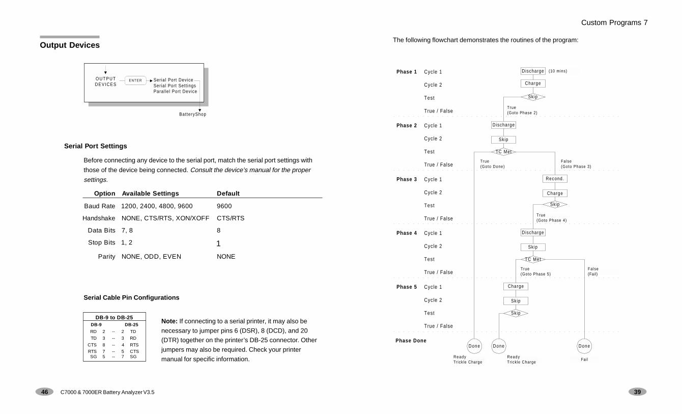
The following flowchart demonstrates the routines of the program:
Custom Programs 7
Cycle 1
Cycle 2
Test
True / False
Cycle 1
Cycle 2
Test
True / False
Cycle 1
Cycle 2
Test
True / False
Cycle 1
Cycle 2
Test
True / False
Cycle 1
Cycle 2
Test
True / False
Phase 1
Phase Done
Phase 2
Phase 3
Phase 5
Phase 4
Discharge
Charge
Discharge
True(Goto Phase 2)
Sk ip
Sk ip
TC Met
Done
True(Goto Done)
Recond.
Charge
Skip
False(Goto Phase 3)
Discharge
Skip
TC Met
True(Goto Phase 4)
Charge
True(Goto Phase 5)
Sk ip
Sk ip
Done
ReadyTr ick le Charge
Fail
Fa lse(Fail)
Done
ReadyTr ick le Charge
(10 mins)
39
Output Devices
Serial Port Settings
Before connecting any device to the serial port, match the serial port settings with
those of the device being connected. Consult the device’s manual for the proper
settings.
Serial Cable Pin Configurations
Option Available Settings Default
Baud Rate 1200, 2400, 4800, 9600 9600
Handshake NONE, CTS/RTS, XON/XOFF CTS/RTS
Data Bits 7, 8 8
Stop Bits 1, 2 1
Parity NONE, ODD, EVEN NONE
DB-9 to DB-25DB-9 DB-25
RD 2 -- 2 TD
TD 3 -- 3 RD
CTS 8 -- 4 RTS
RTS 7 -- 5 CTSSG 5 -- 7 SG
Note: If connecting to a serial printer, it may also be
necessary to jumper pins 6 (DSR), 8 (DCD), and 20
(DTR) together on the printer’s DB-25 connector. Other
jumpers may also be required. Check your printer
manual for specific information.
O U T P U TDEVICES
Seria l Port DeviceSerial Port Sett ingsParal le l Port Device
E N T E R
Bat teryShop
46 C7000 & 7000ER Battery Analyzer V3.5

Creating or Modifying a Custom Program
1. Select Program Settings on the menu. Refer to Menu.
2. Select the program. For example, Custom 1.
3. Press Prog. If applicable, enter the program name, then press ENTER. You
can enter up to 9 characters/numbers. Otherwise press Esc to skip.
4. Enter the program settings.
! Use the """"" and !!!!! keys to scroll through the phases and cycles or select
the settings. Move between the fields using the $$$$$ and ##### keys.
5. Press ENTER when all the settings are entered, then select Yes to accept
changes.
40 C7000 & 7000ER Battery Analyzer V3.5
1. Make sure that no Battery Adapter is inserted.
2. Select Voltage Calibration on the menu.
3. Firmly insert the 4 Voltage Calibration Adapters into each station.
4. Wait for the prompt, then remove the calibration adapters.
5. Press Menu to return to the Global Display.
6. Press Fn-7. The “#” sign should appear in the upper right corner of the
startup screen, indicating successful completion of voltage calibration.
Calibrating Station
Failing to calibrate Battery Adapters could cause inaccurate capacity readings,
especially on low voltage batteries or single cells. Recalibrate adapters when
they are moved from one station to another.
1. Make sure that there is no battery inserted into the adapter.
2. Select Station Calibration on the menu. You can also press Fn-8.
3. For each station, select the station and short the battery leads on the
adapter together using a short length of heavy gauge wire (AWG 10).
Warning: Never short the contacts on the battery.
4. Once the display indicates that a good connection has been established,
press ENTER to start calibrating.
5. Wait for a few seconds and remove the wire when prompted.
System Setup 9
45

8System Security
The C7000 and C7000ER offer three security levels for protection against
tampering: Level 0 (Off) is the default, Level 1 (Low) and Level 2 (High).
Depending on the security level, you will be asked to enter the password for
some features.
A password must have at least 3 digits. You can control the access to the
features by setting the security level.
Password Requirement
41
Setting Up System Information
1. Select the feature on the menu.
2. Enter the required information or select the settings.
! Use the """"" and !!!!! keys to scroll through and select the option, numbers
or characters in both upper and lower cases.
! Use the $$$$$ and ##### keys to move the insertion point.
3. Select Yes to accept changes.
Calibration Procedures
Calibrating Voltage
You need a calibration kit (P/N 92-770-0210). This kit can be purchased from Cadex
or through your Cadex Representative. The C7000 calibration kit consists of 4
calibration adapters (P/N 07-130-0000) and an instruction sheet (P/N 89-204-1017).
Servicing the Voltage Calibration Adapters: Return the Voltage Calibration
Adapters to the factory every 3 years for authorized calibration. Call Cadex for a
Return Authorization number.
44 C7000 & 7000ER Battery Analyzer V3.5
CAL IBRATION Voltage Cal ibrat ionStat ion Cal ibrat ion
E N T E R
Level 0 (Off) Level 1 (Low) Level 2 (High)
C-Code Not required Edit C-Code Edit C-CodeSet Default C-Code
Security Not required Set SecurityChange PasswordRemove Security
Set SecurityChange PasswordRemove Security
System Setup Not required Time/DateProgram SettingsOutput Devices
Time/DateBattery StartupProgram SettingsCompany NameCalibrationOutput DevicesSound ControlVoltage Display
Print Utilities Not required Auto-Print Battery Service ReportBattery LabelBar-Code LabelSystem Setup ReportAuto-Print
Event Log Not required Clear Event LogEvents to Log
Clear Event LogEvents to Log

Setting Security
1. Select Set Security on the menu.
2. Enter the desired security level (0, 1, or 2) or select the security level using the
""""" and !!!!! keys. Then select Yes to accept changes.
Changing Password and Removing Security
! Select Change Password or Remove Security on the menu.
• To change the password (for Level 1 and Level 2), enter the old
password. Then enter and re-enter the new password.
• To remove security, select Yes. Then enter the password.
42 C7000 & 7000ER Battery Analyzer V3.5
9System Setup
43
Feature Description
Time/Date Set up the time and date information printed on BatteryLabels, Battery Service Reports and Event Log.Analyzers with an option board have battery backup RAMthat retains dates and times on power interruption or whenthe analyzer is turned off.
Default: current date and time.
Battery Startup Specify if the analyzer will ask for the Battery ID and/orC-Code when a battery is inserted. Specifying the BatteryID and C-Code prevents the use of wrong settings.
Default: No for Battery ID and Yes for Battery C-Code.
Program Settings Edit program settings. Refer to Editing ProgramSettings.
Company Name Set up the company name for printing on Battery Labelsand Battery Service Reports. You can enter up 20characters/numbers.
Default: CADEX ELECTRONICS.
Calibration(Shortcut: Fn-8)
Correct variations of component tolerances due to aging.Calibrating the voltage once a year maintainsperformance specifications, especially for Li-Ion batteries.Station Calibration compensates for voltage loss fromcables and electrical contacts.
Output Device Connect the analyzer to a printer, label printer orBatteryShop.
Sound Control Turn on or off the audible signals for Key Press eventsand Alert events.
Default: Yes for both Key Press events and Alert events.
Voltage Display Set voltage display mode to Volts/Cell or Volts.
Default: Volts/Cell.