notes - florida department of transportation - home p.) ¡ (b o l t s t y p.) sheeting reflective...
TRANSCRIPT
12/20/2017
1:0
5:1
5 P
M
RE
VISIO
N DESCRIPTION:
REVISION
LAST
ofSTANDARD PLANS
DEVELOPMENTAL INDEX SHEET
4'-
0"
SECTION A-A
(Hatched for Clarity)
Panel Type APanel Type B Panel Type B
A A
SECTION B-B
Panel Type B
¡ Mount to
7 Pcs. @ 1'-0" Sp. = 7'-0"
6 Pcs. @ 1'-0" Sp. = 6'-0"6" Stagger
(Typ.)
Varies @ 1'-0" Sp. = 6'-0" Max.
1'-0" Sp. = 5'-0" Max.6" Stagger
1'-0"
(Typ.)
1'-0"
4'-
0"
Varie
s
3"
Max.
1"
1"
1"
(Typ.)
(Typ.)
1"
4"
"2
11
(Centered)
Nut as Shown
Head Bolt with
" Ø Hex 21¡
"4
3
"81
"4
1"
21
"41
"41
"41
"21
"211
"2
1
4"
D
D
E
E"2
1
1"
"21
3"
Coupler)
(Top
Coupler)
(Bottom
SECTION D-D SECTION E-E
"2
11
1"
"2
1
Steel Plate Coupler
" 41" x 2
14" x 2
"2
12
"2
1"
21
"2
11
"2
1
"2
1
1"
"2
12
Steel Coupler Plates (Typ.)
Pad (Typ.)
" Neoprene 81
2 Pcs. Total)
(1 Pc. Each Face,
Coupler
Steel Plate
" 41" x 2
14" x 2
2 Pcs. Total)
(1 Pc. Each Face,
Coupler
Steel Plate
" 414" x 1" x
4'-
0"
5"±
1"
4"Clear Space
(Typ.)
4"Clear Space
(Typ.)R = 6" (T
yp.)
6'-0"
Type B
6 FT Panel
Panel Type B
Custom Length
Clarity)
(Hatched for
Panel Type A
Panel Type B
¡ Mount to
" (T
yp.)
41
D = 2
"81
"21(Centered) (Typ.)
Ring to Panel
(Plum) (Typ.)
Round Bar
" Ø 21
" Ring 412
Bar (Typ.)
1" Ø Round
(Typ.)
" Ring 412
B
B
(Typ.)
Foundation
Concrete
3'-
0"
NOTES:
(Typ.)
Bar to Bar
(Typ.)
Mid-Height
(Typ.)
Bar to Bar
(See
Note 6)
1'-
0" (T
yp.)
")21(D = 3
" Post Cap43
TYPE B (With Base Mount)
CUSTOM LENGTH PANEL
TYPE A (Without Base Mount)
CUSTOM LENGTH PANEL
")21(D = 3
" Post Cap43
Steel Plate Coupler
" 414" x 1" x
Varies (Custom)
(5 Ft. Max., 3 Ft. Min.)
Ground Line
6"
(Typ.)
INSTALLED FENCE ELEVATION
3"
TYPE A (Without Base Mount)
STANDARD 6 FOOT PANEL
TYPE B (With Base Mount)
STANDARD 6 FOOT PANEL
DETAIL "A"
DETAIL "B"
DETAIL "D" DETAIL "E"
(Typ.)
(See Detail "D")
Top Couplers
(Typ.)
See Detail "C"
(Typ.)
(See Detail "E")
Bottom Couplers
(Typ.)
See Detail "B"
from Top)
(Inserted
3" NPS Pipe
(Embedded)
" NPS Pipe213
(See Note 4) (Typ.)
Schedule 40
" NPS Pipe213
Post Sleeve
3" NPS Pipe
Post Cap to
Pipe
3" NPS
Pipe
3" NPS
Foundation (Typ.)
& Concrete
� Post Sleeve
(Shown Front)
(Shown Back)
(Shown Front)
(Shown Back)
3" NPS Pipe
Post Cap to
Schedule 80 (Typ.)
3" NPS Pipe
" Neoprene Pad81
" Neoprene Pad81
"41 3"
"41 3"
"81
DETAIL "C"
Concrete
Crown
1" (Typ.)
(Typ.)
See Detail "A" (Typ.)
to Post Cap
Round Bar
to Post Cap
Round Bar
D = 1'-0"
"2
1
"21
3"
Washer (Typ.)
Bolt with Nut &
" Ø Hex Head 41
Washer (Typ.)
Bolt with Nut &
" Ø Hex Head 41
Washer (Typ.)
Bolt with Nut &
" Ø Hex Head 41
Washer (Typ.)
Bolt with Nut &
" Ø Hex Head 41
1"
4"
Alum. Sheet)
(Typ.) (Thru
Bolt with Nut
" Ø Hex Head 41
(Typ.)
Mount Bracket
Steel Plate
" 414" x 1" x
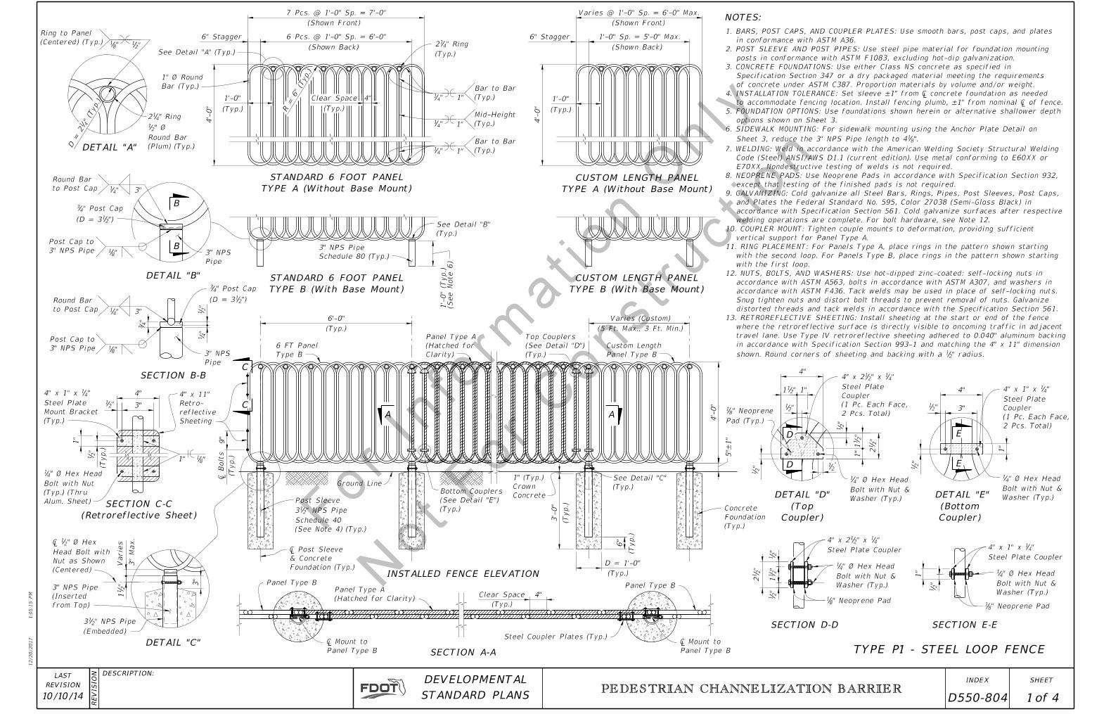
TYPE P1 - STEEL LOOP FENCE
C
C
(Retroreflective Sheet)
SECTION C-C
"811"
9"
(Typ.)
¡ B
olts
(Typ.)
Sheeting
reflective
Retro-
4" x 11"
" radius. 21 shown. Round corners of sheeting and backing with a
in accordance with Specification Section 993-1 and matching the 4" x 11" dimension
travel lane. Use Type IV retroreflective sheeting adhered to 0.040" aluminum backing
where the retroreflective surface is directly visible to oncoming traffic in adjacent
13. RETROREFLECTIVE SHEETING: Install sheeting at the start or end of the fence
distorted threads and tack welds in accordance with the Specification Section 561.
Snug tighten nuts and distort bolt threads to prevent removal of nuts. Galvanize
accordance with ASTM F436. Tack welds may be used in place of self-locking nuts.
accordance with ASTM A563, bolts in accordance with ASTM A307, and washers in
12. NUTS, BOLTS, AND WASHERS: Use hot-dipped zinc-coated: self-locking nuts in
with the first loop.
with the second loop. For Panels Type B, place rings in the pattern shown starting
11. RING PLACEMENT: For Panels Type A, place rings in the pattern shown starting
vertical support for Panel Type A.
10. COUPLER MOUNT: Tighten couple mounts to deformation, providing sufficient
welding operations are complete. For bolt hardware, see Note 12.
accordance with Specification Section 561. Cold galvanize surfaces after respective
and Plates the Federal Standard No. 595, Color 27038 (Semi-Gloss Black) in
9. GALVANIZING: Cold galvanize all Steel Bars, Rings, Pipes, Post Sleeves, Post Caps,
except that testing of the finished pads is not required.
8. NEOPRENE PADS: Use Neoprene Pads in accordance with Specification Section 932,
E70XX. Nondestructive testing of welds is not required.
Code (Steel) ANSI/AWS D1.1 (current edition). Use metal conforming to E60XX or
7. WELDING: Weld in accordance with the American Welding Society Structural Welding
". 81 Sheet 3, reduce the 3" NPS Pipe length to 4
6. SIDEWALK MOUNTING: For sidewalk mounting using the Anchor Plate Detail on
options shown on Sheet 3.
5. FOUNDATION OPTIONS: Use foundations shown herein or alternative shallower depth
to accommodate fencing location. Install fencing plumb, ±1" from nominal ¡ of fence.
4. INSTALLATION TOLERANCE: Set sleeve ±1" from ¡ concrete foundation as needed
of concrete under ASTM C387. Proportion materials by volume and/or weight.
Specification Section 347 or a dry packaged material meeting the requirements
3. CONCRETE FOUNDATIONS: Use either Class NS concrete as specified in
posts in conformance with ASTM F1083, excluding hot-dip galvanization.
2. POST SLEEVE AND POST PIPES: Use steel pipe material for foundation mounting
in conformance with ASTM A36.
1. BARS, POST CAPS, AND COUPLER PLATES: Use smooth bars, post caps, and plates
PEDESTRIAN CHANNELIZATION BARRIER
10/10/14 1 4 D550-804
2'-0" Centers
Hog Rings @ Tension Wire
� End Post
Tension Wire
@ 1'-3" Centers) (Typ.)
Bar ~ Space Equally
required per Tension
Tension Bands (4
Varies (8" Max.)
Line Posts
Equal Spacing
(Adjacent Space)
End Post (Typ.)
� Line Post (Typ.)
(Adjacent Spaces)
(Typ.)
Brace Rail
2'-0" Centers
Hog Rings @
4'-0" 4'-0" 4'-0"
10'-0" Max. 10'-0" Max.
Line Post Line Post Line Post
Centers (Typ.)
Ties @ 1'-0"
(Typ.)
Tension BarChain Link Fabric
Centers (Typ.)
Ties @ 1'-6"
Varies (8" Max.)
Line Post
4'-
0"
Ground Line
COMPONENT INFORMATIONASTM NO.
Posts F 1083
Tie Wires
COMPONENT
F 626
F 1083
F 626
Class 4 Coating
Type II (Zinc Coated Steel Wire) - No. 7 gage,
Brace Rails
Zinc Coated Steel Wire - No. 9 gage
Tension Wire
F 626
Brace Rail Bands
Zinc Coated Steel Wire - No. 12 gageF 626Hog Rings
Tension Bars
Tension Bands
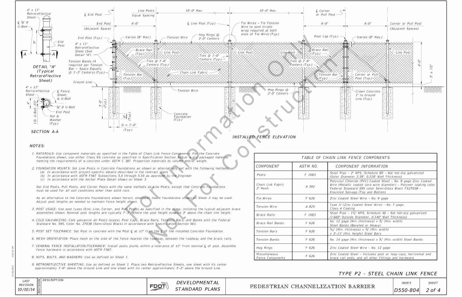
TABLE OF CHAIN LINK FENCE COMPONENTS
INSTALLED FENCE ELEVATION
Centers (Typ.)
Ties @ 1'-6"
(Typ.)
Brace Rail
(Typ.)
Tension Bar
(Typ.)Foundation Concrete
Post (Typ.)
Corner or Pull
NOTES:
2" Mesh
Chain Link Fabric
ends of Tie Wire) (Typ.)
wrap required at both
Wire to post (triple
Tie Wires - Tie Tension
or Pull Post
� Corner
TYPE P2 - STEEL CHAIN LINK FENCE
Line (Typ.)
1" to Ground
Crown Concrete
3'-
0"
(Typ.)
6"
(Typ.)
F 626
A 392
x 3'-11" (Min. height) Steel Bars
" (Min. width) 43" (Min. thickness) x 16
3
Steel Bands (Beveled or Heavy)
" (Min. width) 43No. 12 gage (Min. thickness) x
A 824
D = 1'-0"
(Typ.)
End Post Corner or Pull Post
" (Min. width) Steel Bands43No. 14 gage (Min. thickness) x
(1.660" Outside Diameter, 0.140" Wall Thickness)
" NPS, Schedule 40 - Not hot-dip galvanized41Steel Pipe - 1
(Outer Diameter 2.38", 0.218" Wall Thickness)
Steel Pipe - 2" NPS, Schedule 80 - Not hot-dip galvanized
Post Cap (Typ.)
DETAIL "A"
A A
9"
Detail "A")
Sheet (See
Retroreflective
4" x 11"
& U-Bolt
Sheet,
¡ Fence,
4"
"2
12
I.D.
U-B
olt
Sheet
Retroreflective
4" x 11"
SECTION A-A
End Post
Post
End
Sheet)
Retroreflective
(Typical
Sheet
Retroreflective
4" x 11"
Fence Components
Miscellaneous F 626
brace rail ends, and all other fittings and hardware
Zinc Coated Steel - Includes post or loop caps, horizontal and
(Typ.)
Washer
Nut &
U-Bolt
" Ø83¡
" Ø U-Bolt83
Knuckled Selvage (Top and Bottom)
Federal Standard 595 color Semi-Gloss Black FS27038 -
Wire (Metallic coated core wire diameter) - Polymer coating color
Polyvinyl Chloride (PVC) Coated Steel - No. 9 gage Zinc Coated
" 2
13"
± 1
approximately 1'-6" above the Ground Line and one sheet with its center approximately 3'-2" above the Ground Line.
9. RETROREFLECTIVE SHEETING: Use as defined on Sheet 1. Place two Retroreflective Sheets, one sheet with its center
8. NUTS, BOLTS, AND WASHERS: Use as defined on Sheet 1.
fence hardware in accordance with ASTM F567.
7. GENERAL FENCE INSTALLATION/TOLERANCE: Install posts plumb, within a tolerance of ±1" from nominal � of post. Assemble
6. MESH ORIENTATION: Place mesh on the side of the fence nearest the roadway, between the roadway and the brace rails.
5. POST SET TOLERANCE: Set Post in concrete with the Post � at ±1" from the � of the installed Concrete Foundation.
Standard No. 595, Color No. 27038 (Semi-Gloss Black) in accordance with Specification Section 561.
4. COLD GALVANIZING: Cold galvanize all Posts (pipes), Post Caps, Brace Rails, Tensions Bars, and Bands with the Federal
assemblies shown. Nominal post lengths are typically 7'-1", where the post height extends 3" above the chain link height.
3. POST USAGE: Use post types (End, Line, Corner, and Pull Posts) as specified in the plans, including the typical adjacent brace
Adjust post lengths as needed to maintain fence height shown.
As an alternative to the Concrete Foundations shown herein, shallower mount foundations shown on Sheet 3 may be used.
must be used for all soil conditions other than solid rock.
Set End Posts, Pull Posts, and Corner Posts with the same methods as Line Posts, except that Concrete Foundations
(c) In accordance with the Anchor Plate Detail shown on Sheet 3
(b) In accordance with ASTM F567 Subsections 5.4 through 5.10 as approved by the Engineer
(a) In accordance with project-specific details described in the contract plans
2. FOUNDATION MOUNTS: Set Line Posts in Concrete Foundations as shown or alternatively set with the following methods:
meeting the requirements of a concrete under ASTM C 387. Proportion materials by volume and/or weight.
Foundations shown, use either Class NS concrete as specified in Specification Section 347 or a dry packaged material
1. MATERIALS: Use component materials as specified in the Table of Chain Link Fence Components. For the Concrete
12/20/2017
1:0
5:1
6 P
M
RE
VISIO
N DESCRIPTION:
REVISION
LAST
ofSTANDARD PLANS
DEVELOPMENTAL INDEX SHEET
PEDESTRIAN CHANNELIZATION BARRIER
10/10/14 2 4 D550-804
45°
Back of Curb
2 Ft. Utility Strip
4'-
6"
45°
4'-
6"
Back of Curb
1'-4"
1'-6"
Varies
Stability of Fencing)
(3' Min. Width Required for
5"
Thickened Edge
4" Sidewalk with
Thickened Edge
4" Sidewalk with
BoltAnchor
1'-
0"
Back of Curb
2'-0"Max. Max.
& Fence
� Bolts, Post,
& Fence
� Bolts, Post,
Surface
Roadway
Surface
Roadway
PlateAnchor
NOTES:
SECTION WITH UTILITY STRIP
OPTION 1 - NEW CONSTRUCTION
SECTION WITHOUT UTILITY STRIP
OPTION 2 - NEW CONSTRUCTION
1'-6" Min.
Max.
Fence
Heig
ht (T
yp.)
Max.
Fence
Heig
ht (T
yp.)
Max.
Fence
Heig
ht (T
yp.)
4'-
6"
Varies
Stability of Fencing)
(3' Min. Width Required for
9"
ADJACENT SIDEWALK MOUNTING OPTIONS
Foundation
Concrete
Surface
Roadway
SHALLOW CONCRETE FOUNDATION
OPTION 3 - NEW OR EXISTING SIDEWALK
6"
1"
"43
"214
4"
Type P1
Type P2
6"
"411
(Typ.)
and Post¡ Bolts 3
"
ANCHOR PLATE DETAIL
TYPE P1 FENCE
" 214
9"
6"
3"
"165
"411
(Typ.)
4"
and Post¡ Bolts
" Steel Plate85
ANCHOR PLATE DETAIL
TYPE P2 FENCE
8"
6"
Bonding Material
" Bed of Adhesive 211
required
x thickness as
" Wide43x
8" to 9" Long
Optional Edge Shim
adjustment
for height
Plate as required
Standard Shim
& Fence
� Post
PadNeoprene
PlateAnchor
PadNeoprene
BoltAnchor
Post
PlateAluminum
" 81
3"
PLATE DETAIL
STANDARD SHIM
OPTIONS DETAIL
SHIM PLATE MOUNT
2'-
0"
2'-0"
4" Sidewalk
1"
Post Post
Anchor Plate
3" NPS Pipe to
Anchor Plate
2" NPS Pipe to
1'-
0"
" Steel Plate21
Washer
Hex Nut &
Bolt with
" Anchor 43
"81
D = 2'-0"
Pad
" Neoprene81
Concrete
Cro
wn
Anchor Bolt (Typ.)
" 43" Ø Hole for 8
7
Anchor Bolt (Typ.)
" 43" Ø Hole for 8
7
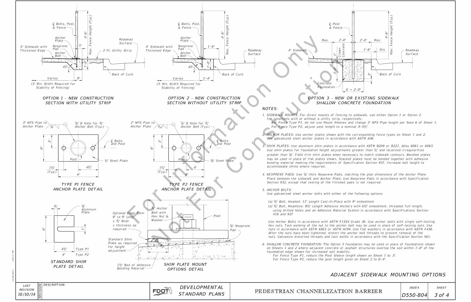
For Fence Type P2, reduce the post length given on Sheet 2 to 6'-4".
For Fence Type P1, reduce the Post Sleeve length shown on Sheet 1 by 3".
foundation edge shown for increased soil stability.
on Sheets 1 and 2 where adjacent concrete or asphalt structures overtop the soil within 1'-0" of the
6. SHALLOW CONCRETE FOUNDATION: The Option 3 foundation may be used in place of foundations shown
nuts. Galvanize distorted threads and tack welds in accordance with the Specification Section 561.
After the nuts have been tightened, distort the anchor bolt threads to prevent removal of the
nuts in accordance with ASTM A563 or ASTM A194. Use flat washers in accordance with ASTM F436.
hex nuts. Tack welding of the nut to the anchor bolt may be used in place of self-locking nuts. Use
Use Anchor Bolts in accordance with ASTM F1554 Grade 36. Use anchor bolts with single self-locking
416 and 937
using drilled holes and an Adhesive Material System in accordance with Specifications Section
" embedment, threaded full length,21" Length Adhesive Anchors with 62
1" Bolt, Headless: 843 (b)
" Bolt, Headed: 11" Length Cast-In-Place with 9" embedment43 (a)
Use galvanized steel anchor bolts with either of the following options:
5. ANCHOR BOLTS:
Section 932, except that testing of the finished pads is not required.
Place between the sidewalk and Anchor Plate. Use Neoprene Pads in accordance with Specification
" thick Neoprene Pads, matching the plan dimensions of the Anchor Plate. 814. NEOPRENE PADS: Use
accommodate shims where required.
bonding material meeting the requirements of Specification Section 937. Increase bolt length to
may be used in place of flat plates shown. Stacked plates must be bonded together with adhesive
". Field trim shim plates when necessary to match sidewalk contours. Beveled plates 81 greater than
" and localized irregularities 41 Use shim plates for foundation height adjustments greater than
3. SHIM PLATES: Use aluminum shim plates in accordance with ASTM B209 or B221, Alloy 6061 or 6063.
Use galvanized steel anchor plates in accordance with ASTM A36.
2. ANCHOR PLATES: Use anchor plates shown with the corresponding fence types on Sheet 1 and 2.
"21 For Fence Type P2, adjust post length to a nominal 4'-5
For Fence Type P1, do not use Mount Sleeves and change 3" NPS Pipe length per Note 6 of Sheet 1.
for conditions with or without a utility strip, respectively.
1. SIDEWALK MOUNTS: For direct mounts of fencing to sidewalk, use either Option 1 or Option 2
12/20/2017
1:0
5:1
7 P
M
RE
VISIO
N DESCRIPTION:
REVISION
LAST
ofSTANDARD PLANS
DEVELOPMENTAL INDEX SHEET
PEDESTRIAN CHANNELIZATION BARRIER
10/10/14 3 4 D550-804
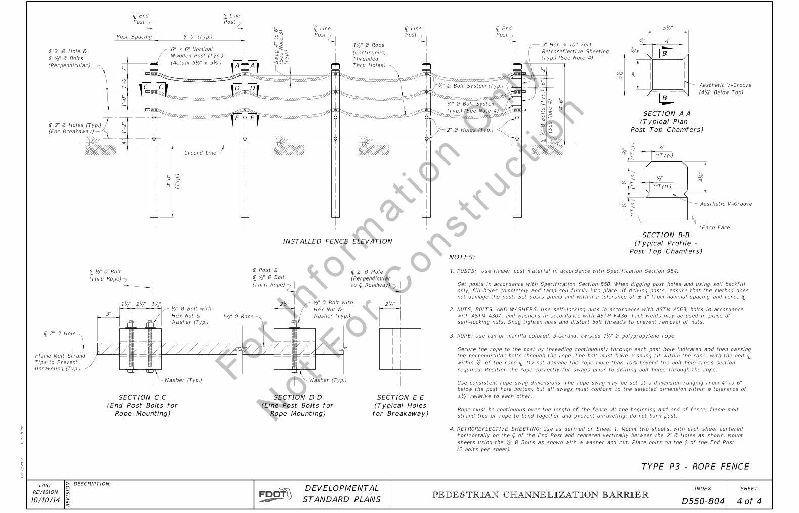
TYPE P3 - ROPE FENCE
B
B
"215
"43
4"
"2
15
"4
3
INSTALLED FENCE ELEVATION
4'-
0"
(Typ.)
CC D D
A A
1'-
0"
1'-
0"
"211 "2
12 "211 "4
32
(For Breakaway)
¡ 2" Ø Holes (Typ.)1'-
2"
4"
¡ 2" Ø Hole
(Thru Rope)
" Ø Bolt21¡
¡ Post &
(Thru Rope)
" Ø Bolt21¡
Post
¡ End
Post
¡ Line
Post
¡ Line
Post
¡ Line
Post
¡ End
"432
to ¡ Roadway)
(Perpendicular
¡ 2" Ø Hole
3"
2" Ø Holes (Typ.)
Rope Mounting)
(End Post Bolts for
SECTION C-C
Rope Mounting)
(Line Post Bolts for
SECTION D-D
Washer (Typ.)Washer (Typ.)
4"
7"
4'-
6"
NOTES:
"43
"4
3"
21
"2
1
"4
14
(*Typ.)
(*Typ.)
*Each Face
"21
(*Typ.)
(*Typ.)
(*Typ.)
Thru Holes)
Threaded
(Continuous,
" Ø Rope 211
Unraveling (Typ.)
Tips to Prevent
Flame Melt Strand
E E
" Ø Bolt System (Typ.)21
" Ø Rope211
(Typ.)
(See
Note 3)
Swag 4" to 6"
Post Top Chamfers)
(Typical Plan -
SECTION A-A
Post Top Chamfers)
(Typical Profile -
SECTION B-B
for Breakaway)
(Typical Holes
SECTION E-E
Aesthetic V-Groove
" Below Top)41(4
Aesthetic V-Groove
Ground Line
Washer (Typ.)
Hex Nut &
" Ø Bolt with 21
Washer (Typ.)
Hex Nut &
" Ø Bolt with 21
Post Spacing 5'-0" (Typ.)
")21" x 52
1(Actual 5
Wooden Post (Typ.)
6" x 6" Nominal
(Perpendicular)
" Ø Bolts21¡
¡ 2" Ø Hole &
2"
6"
(See
Note 4)
" Ø B
olts (T
yp.)
21
¡
(Typ.) (See Note 4)
Retroreflective Sheeting
5" Hor. x 10" Vert.
(Typ.) (See Note 4)
" Ø Bolt System 21
(2 bolts per sheet).
" Ø Bolts as shown with a washer and nut. Place bolts on the ¡ of the End Post 21 sheets using the
horizontally on the ¡ of the End Post and centered vertically between the 2" Ø Holes as shown. Mount
4. RETROREFLECTIVE SHEETING: Use as defined on Sheet 1. Mount two sheets, with each sheet centered
strand tips of rope to bond together and prevent unraveling; do not burn post.
Rope must be continuous over the length of the fence. At the beginning and end of fence, flame-melt
" relative to each other.21 ±
below the post hole bottom, but all swags must conform to the selected dimension within a tolerance of
Use consistent rope swag dimensions. The rope swag may be set at a dimension ranging from 4" to 6"
required. Position the rope correctly for swags prior to drilling bolt holes through the rope.
" of the rope ¡. Do not damage the rope more than 10% beyond the bolt hole cross section 81 within
the perpendicular bolts through the rope. The bolt must have a snung fit within the rope, with the bolt �
Secure the rope to the post by threading continuously through each post hole indicated and then passing
" Ø polypropylene rope. 213. ROPE: Use tan or manilla colored, 3-strand, twisted 1
self-locking nuts. Snug tighten nuts and distort bolt threads to prevent removal of nuts.
with ASTM A307, and washers in accordance with ASTM F436. Tack welds may be used in place of
2. NUTS, BOLTS, AND WASHERS: Use self-locking nuts in accordance with ASTM A563, bolts in accordance
not damage the post. Set posts plumb and within a tolerance of ± 1" from nominal spacing and fence �.
only, fill holes completely and tamp soil firmly into place. If driving posts, ensure that the method does
Set posts in accordance with Specification Section 550. When digging post holes and using soil backfill
1. POSTS: Use timber post material in accordance with Specification Section 954.
12/20/2017
1:0
5:1
8 P
M
RE
VISIO
N DESCRIPTION:
REVISION
LAST
ofSTANDARD PLANS
DEVELOPMENTAL INDEX SHEET
PEDESTRIAN CHANNELIZATION BARRIER
10/10/14 4 4 D550-804