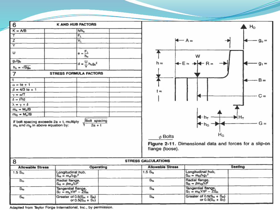
notes (loose type flanges): (1) for hub tapers 6 deg or less, use go = g1. (2) loading and...
TRANSCRIPT

فلنچ : طراحی پروژه موضوع ها
تعالی باسمه

ها فلنج طراحیپروژه : موضوع

لق -1 های فلنج
کامل - 2 و صحیح های فلنج) مکمل)
انتخابی -3 های فلنج
شکل ای دایره های فلنج انواع


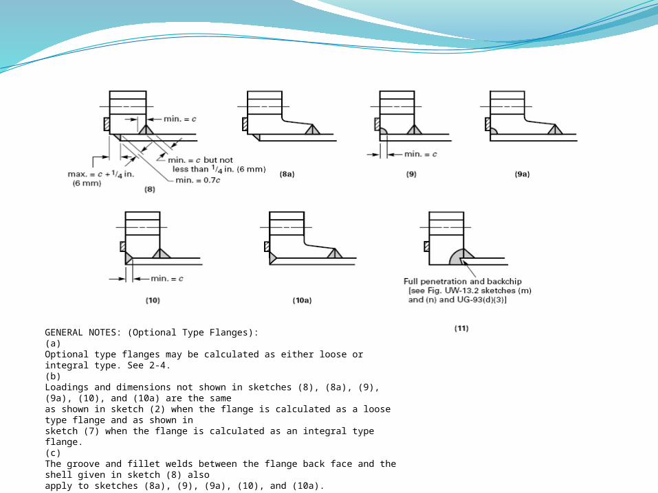
GENERAL NOTES: (Optional Type Flanges):(a)Optional type flanges may be calculated as either loose or integral type. See 2-4.(b)Loadings and dimensions not shown in sketches (8), (8a), (9), (9a), (10), and (10a) are the sameas shown in sketch (2) when the flange is calculated as a loose type flange and as shown insketch (7) when the flange is calculated as an integral type flange.(c)The groove and fillet welds between the flange back face and the shell given in sketch (8) alsoapply to sketches (8a), (9), (9a), (10), and (10a).

قطر خارجی فلنچسطح مقطع عرض پیچ
کل مقاطع عرضی برش خورده قطر اسمی پیچقطر داخلی فلنچ
قطر داخلی انتخابی فلنچمساحت پیچ
درزبند عرض موثرمحل قرار گرفتن درز بند
قطر پیچفاکتور قالب توپیقطر سوراخ پیچ
اندازه شعاعفاکتور قالب توپی
فاکتور قالب توپی برای انواع فلنچ های صحیح و کامل فاکتور قالب توپی برای انواع فلنچ های لغرا ن وگشاد
فاکتور صحیح تش توپی برای فلنچ های صحیحعکس العمل بار قطر ی درز بندکمترین ضخانمت از نوک توپی
ضخامت توپی پشت فلنچ
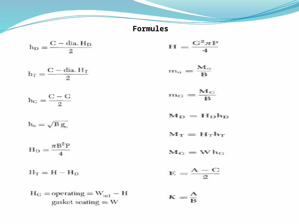
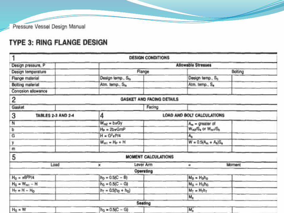
A = flange O.D., in.Ab =cross-sectional area of bolts, in.2Am =total required cross-sectional area of bolts, in2a = nominal bolt diameter, in.B =flange I.D., in. (see Note 6)BI =flange I.D., in. )see Note 6(Bs=bolt spacing, in.b = effective gasket width, in.Bo = gasket seating width, in.C =bolt circle diameter, in.d =hub shape factord1 =bolt hole diameter, in.E, hd, hc, hT, R =radial distances, in.e =hub shape factorF =hub shape factor for integral-type flangesFL, =hub shape factor for loose-type flangesf = hub stress correction factor for integralflangesG = diameter at gasket load reaction, in.Go =thickness of hub at small end, in.gl =thickness of hub at back of flange, in.
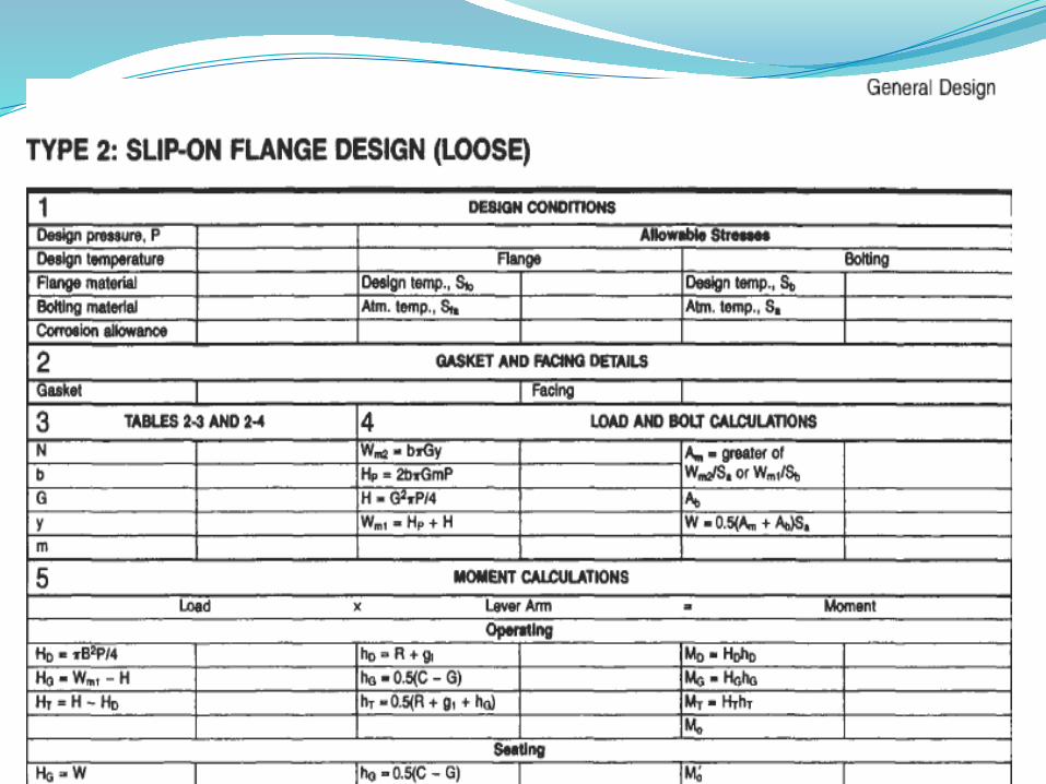
DESIGN OF FLANGES

H =hydrostatic end force, lbHd =hydrostatic end force on area inside o flange , lbHg = gasket load, operating, lbHp = total joint-contact surface compression load, lbHt =pressure force on flange face, lbh =hub length, in.ho =hub factorMD = moment due to HD, in.-lbMG = moment due to HG, in.-lbM, =total moment on flange, operating, n.&ML =total moment on flange, seatingMT = moment due to HT, in.-lbm, = unit load, operating, lbmg = unit load, gasket seating, lbm = gasket factor (see Table 2-3)N =width of gasket, in. (see Table 2-4)w =width of raised face or gasket contact width,n = number of bolts
نیروی هیدرواستاتیک نیروی هیدرو استاتیک روی
سطح داخلی فلنجبار درزبند در حین عملیات
کل سطح تماس اتصال زیر فشار بارنیروی فشار روی سطح فلنچ
طول توپیفاکتور توپی
گشتاور ناشی از نیروی هیدرو استاتیک رو ی
از ناشی hgگشتاورعملیات حین در فلنچ روی گشتاور کل
گاه تکیه در فلنچ روی گشتاور کلاز ناشی گشتاور HTکلجدول ( بند درز )2-3فاکتور
عملیات حین در بار واحدگیری قرار محل در بار GASKETواحدجدول ( بند درز )2-4عرض
عرضی تماس در یا عرضی سطح آمدگی برپیچ شماره
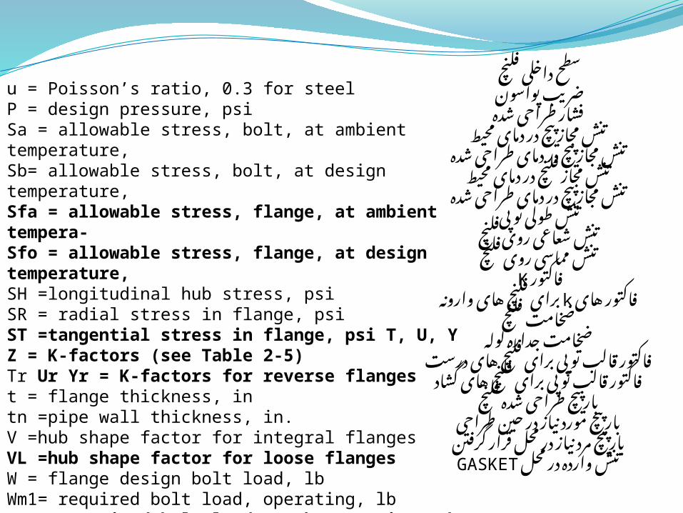
u = Poisson’s ratio, 0.3 for steelP = design pressure, psiSa = allowable stress, bolt, at ambient temperature,Sb= allowable stress, bolt, at design temperature,Sfa = allowable stress, flange, at ambient tempera-Sfo = allowable stress, flange, at design temperature,SH =longitudinal hub stress, psiSR = radial stress in flange, psiST =tangential stress in flange, psi T, U, YZ = K-factors )see Table 2-5(Tr Ur Yr = K-factors for reverse flanges t = flange thickness, intn =pipe wall thickness, in.V =hub shape factor for integral flangesVL =hub shape factor for loose flangesW = flange design bolt load, lbWm1= required bolt load, operating, lbWm2=2 required bolt load, gasket seating, Iby = gasket design seating stress, psi
سطح داخلی فلنچ پواسون ضریب
شده طراحی فشارمحیط دمای در پیچ مجاز تنش
شده طراحی دمای در پیچ مجاز تنشمحیط دمای در فلنچ مجاز تنش
شده طراحی دمای در پیچ مجاز تنشتوپی طولی تنش
فلنچ روی شعاعی تنشفلنچ روی مماسی تنش
Kفاکتور های وارونه kفاکتور های فلنچ برای
فلنچ ضخامتلوله جداره ضخامت
درست های فلنچ برای توپی قالب فاکتورگشاد های فلنچ برای توپی قالب فاکتور
فلنچ شده طراحی پیچ بارطراحی حین در نیاز مورد پیچ بار
گرفتن قرار محل در نیاز مرد پیچ بارمحل در وارده GASKETتنش
Formules


Special Flanges
Special flanges that are required to be designed shouldonly be used as a last resort. Whenever possible, standardflanges should be utilized. In general, special designs as outlinedin this procedure are done for large or high-pressuredesigns. Flanges in this category will be governed by one oft u 7 0 conditions:1. Gasket seating force, Wm72. Hydrostatic end force, HFor high-pressure flanges, typically the hydrostatic endforce, H, will govern. For low-pressure flanges, the gasketseating force will govern. Therefore the strategy forapproaching the design of these flanges will vary. The strategyis as follows:

For low-pressure flanger<I. Minimize the gasket width to reduce the force necessaryto seat the gasket.b LJse a larger number of smaller diameter bolts to minimizethe bolt circle diameter and thus reduce themoment drm which governs the flange thickness.c Utilize liubless flanges (either lap joint or plate flanges)to minimize the cost of forgings.e For high-pressure jlangesHigh-pressure flanges require a large bolt area to counteractthe large hydrostatic end force. Large bolts, in turn,increase the bolt circle with a corresponding increase inthe moment arm. Thicker flanges and large hubs arenecessary to distribute the bolt loads. Seek a balancebetween the quantity and size of bolts, bolt spacing, andbolt circle diameter.

Design Strategy
Step 1: Determine the number and size of bolts required. Asa rule of thumb, start with a number of bolts equal to thenominal size of the bore in inches, rounded to the nearestmultiple of four. First, calculate Wlnl or Wm2, A,, is equalto the larger of Wm1 or Wm2 divided by Sa The quantity of bolts required is:n = Am/RaTo find the size of bolt for a given quantity:R,= Am/nWith these two equations a variety of coinbinations can bedetermined.Step 2: Determine the bolt circle diameter for the selectedbolt size.C = B + 2g1+2RThe flange O.D. may now be established.A=C+2E

Step 3: Check the minimum bolt spacing (not an ASME
requirement). Coinpare with the value of B, in Table 2-5a.
B, = C/n
Note: Dimensions R,, R, E, and B, are from Table 2-5a.
Step 4: After all of the preliminary dimensions and details
are selected, proceed with the detailed analysis of theflange by calculating the balance of forces, moments,and stresses in the appropriate design form.

Gasket Facing and Selection
The gasket facing and type correspond to the service conditions,
fluid or gas handled, pressure, temperature, thermal
shock, cyclic operation, and the gasket selection. The greater
the hazard, the more care that should be invested in the
decisions regarding gasket selection and facing details.
Facings which confine the gasket, male and female,
tongue and groove and ring joint offer greater security
against blowouts. Male and fernale and tongue and groove
have the disadvantage that mating flanges are not alike.
These facings, which confine the gasket, are known as enclosed
gaskets and are required for certain services, such as
TEMA Class “R.”


For tongue and groove flanges, the tongue is more likely
to
be damaged than the groove; therefore, from a maintenance
standpoint, there is an advantage in placing the tongue on
the part which can be transported for servicing, i.e., blind
flanges, manway heads, etc. If the assembly of these joints
is horizontal then there will be less difficulty if the groove is
placed in the lower side of the joint. The gasket width should
be made equal to the width of the tongue. Gaskets for these
joints are typically metal or metal jacketed.


In general, bolts should always be used in multiples of4. For large-diameter flanges, use many smaller boltson a tight bolt circle to reduce the flange thickness.Larger bolts require a large bolt circle, which greatlyincreases flange thickness. If the bolt holes are slotted to allow for swing-awaybolting, substitute the diameter of the circle tangentto the inner edges of the slots for dimension A andfollow the appropriate design procedures. Square and oval flanges with circular bores should betreated as “inscribed” circular flanges. Use a bolt circlepassing through the center of the outermost bolt holes.The same applies for noncircular openings; however,
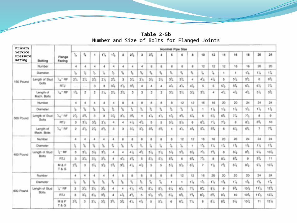
Table 2-5bNumber and Size of Bolts for Flanged Joints
PrimaryServicePressureRating

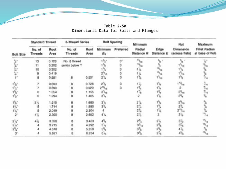
Table 2-5aDimensional Data for Bolts and Flanges

Table 2-3Gasket Materials and Contact Facings'
Gasket Factors (m) for Operating Conditions and Minimum Design Seating Stress (y)
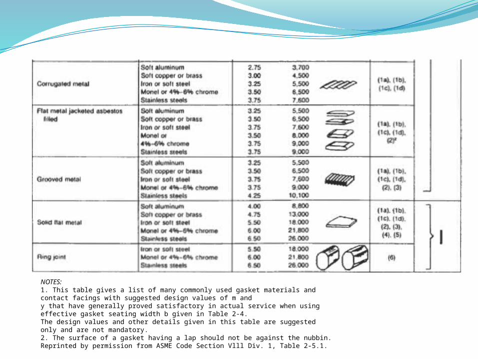
NOTES:1. This table gives a list of many commonly used gasket materials and contact facings with suggested design values of m andy that have generally proved satisfactory in actual service when using effective gasket seating width b given in Table 2-4.The design values and other details given in this table are suggested only and are not mandatory.2. The surface of a gasket having a lap should not be against the nubbin.Reprinted by permission from ASME Code Section Vlll Div. 1, Table 2-5.1.

Table 2-4Effective Gasket Width

*Where serrations do not exceed %+in. depth and lk-in. width spacing, sketches (lb) and (Id) shall be used.Reprinted by permission from ASME Code Section Vlll Div. 1, Table 2-52,

Table 2-5Table of Coefficients

Table 2-5Table of Coefficients )Continued(
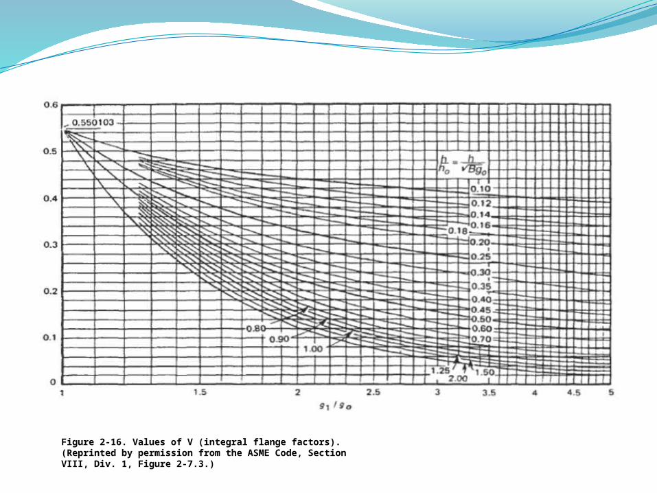
Figure 2-16. Values of V )integral flange factors(. )Reprinted by permission from the ASME Code, Section VIII, Div. 1, Figure 2-7.3.(
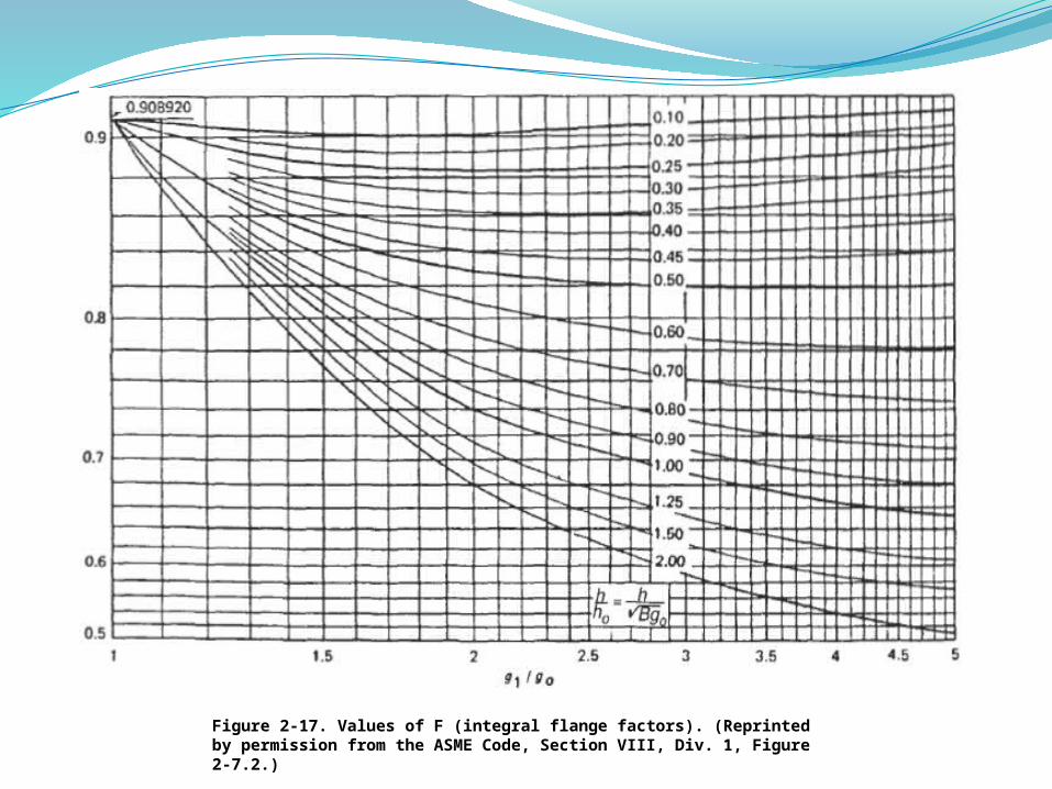
Figure 2-17. Values of F )integral flange factors(. )Reprinted by permission from the ASME Code, Section VIII, Div. 1, Figure 2-7.2.(
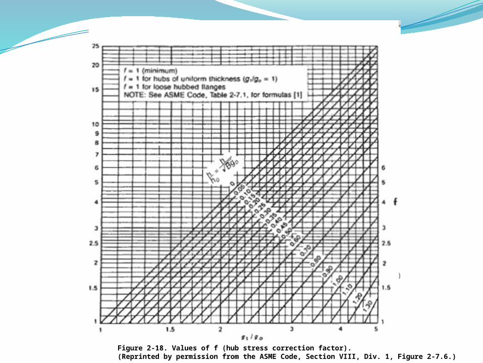
Figure 2-18. Values of f )hub stress correction factor(. )Reprinted by permission from the ASME Code, Section VIII, Div. 1, Figure 2-7.6.(

Figure 2-20. Values Of FL )loose hub flange factors(. )Reprinted byPermission from the ASME Code, Section VIII, Div. 1, Figure 2-7.4.)
Figure 2-19. Values of VL )loose hub flange factors(. )Reprinted bypermission from the ASME Code, Section VIII, Div. 1, Figure 2-7.5.)