notes on aisi design methods for sheathing braced … on aisi design methods...aisi design methods...
TRANSCRIPT

1
Notes on AISI Design Methods for Sheathing Braced Design
of Wall Studs in Compression
April 20081
B.W. Schafer1, L. Vieira2, O. Iourio3
(1) Associate Professor, Johns Hopkins University (2) Graduate Research Assistant, Johns Hopkins University (3) Visiting Research Student, University of Naples
Progress Report to AISI-COFS Project Monitoring Task Group
(Nabil Rahman Chair) Purpose This is an informal progress report document summarizing recent work on the development of a design method for sheathing braced design of wall studs with dissimilar sheathing. This document focuses on only one aspect of the ongoing work: a critical review of existing design methods for wall studs in compression. The document concludes with a list of limit states that should potentially be checked for a sheathed wall stud in compression. (Progress on other aspects of the project including the experimental work is ongoing, but not reported in this document.) The goals of this document include: to fully understand the technical basis for existing and past design methods, to resolve the local vs. diaphragm stiffness design debate, to understand what existing methods do well and what they miss with respect to design, and to lay the ground work for the creation of a comprehensive design method for a sheathed wall stud. Summary The 1962 AISI Specification provides the groundwork for rational requirements on stud-fastener-sheathing strength and stiffness – these requirements need to be reflected in future design methods in some form. The diaphragm based design method of Simaan and Peköz (AISI method from 1980-2004) provides significant theoretical insights on how to incorporate torsional-flexural buckling including with one-sided and dis-similar sheathing, but the particulars of the model for the diaphragm are not physically realizable, thus modifications are a must. The limitations inherent in the current AISI-COFS Wall Stud Standard (AISI-S211-07) are noted and discussed. A preliminary list of limit states for sheathed wall studs in compression is provided.
1 revised from January 2008 to include comments from AISI-COFS PMTG

2
Table of Contents 1 Notes on … 1962 AISI Specification for Wall Studs in Compression................................... 3
1.1 Design assumptions inherent in amax1 ............................................................................. 4 1.2 Design assumptions inherent in amax2 ............................................................................. 5 1.3 Design assumptions inherent in kmin ............................................................................... 5 1.4 Design assumption inherent in Fmin ................................................................................ 6 1.5 Test for Determination of available k ............................................................................. 8 1.6 Summary of AISI 1962 requirements ............................................................................. 8
2 Notes on .. 2001 AISI Specification for Wall Studs in Compression..................................... 9 2.1 Design assumptions inherent in Pcr (σcr)....................................................................... 10 2.2 Test for determination of Q........................................................................................... 11 2.3 Use of Q tests to determine k instead............................................................................ 12 2.4 Additional method for determining k from Q test ........................................................ 13
3 Notes on… 2007 AISI-COFS Specification for Wall Studs in Compression ...................... 14 3.1 Design assumptions related to identical or weaker-of-the-two sheathing (B1(b)) ....... 14 3.2 Design assumptions inherent in determining global buckling load Pcr......................... 15 3.3 Comparison of AISI 2007 (S211-07) with 1962 AISI Specification w.r.t Pcr .............. 15 3.4 Design assumptions related to member end conditions................................................ 16 3.5 Discussion of commentary application of 2% rule for fasteners .................................. 16 3.6 Equivalence between 2007 cited Winter model and 1962 Specification...................... 17 3.7 Winter’s prediction for the role of fastener spacing (getting beyond the 2% rule) ...... 18 3.8 Summary of findings w.r.t the application of 2% rule in AISI-S211-07 Commentary 18 3.9 Given fastener demands, what to check?...................................................................... 18 3.10 Discussion of Gypsum wall board provisions .............................................................. 18
4 Comparison of ‘k’ values from different test methods ......................................................... 19 4.1 Winter (1962 Spec.) tests vs. Simaan and Peköz Diaphragm tests............................... 19 4.2 Comparison of k values from other tests ...................................................................... 20 4.3 Additional discussion of local fastener k tests.............................................................. 20
5 Design of a sheathed wall stud in compression .................................................................... 22 5.1 Demand ......................................................................................................................... 22 5.2 Capacity/Limit States.................................................................................................... 24
6 References............................................................................................................................. 30

3
1 Notes on … 1962 AISI Specification for Wall Studs in Compression Even today, the 1962 AISI Specification (AISI 1962) for walls studs is often put forth as a reasonable and well considered method for the design of sheathed studs. In fact, design procedures in current use, namely AISI-S211-07 (AISI 2007) the “Wall Stud Standard,” have their genesis in this method. Here we explore the requirements of this method and both their theoretical basis and empirical decisions. The premise of the 1962 Specification is well stated in the Specification itself, namely:
“The safe load-carrying capacity of a stud may be computed on the basis that the wall material or sheathing (attached to the stud) furnishes adequate lateral support to the stud in the plane of the wall, provided the wall material and its attachments to the stud comply with the following requirements:”
The stated requirements include that the “Wall material or sheathing must be attached to both faces or flanges of the studs being braced.” and then proceed to the design expressions. The maximum center-to-center spacing of fasteners must be less than amax1 and amax2, where
222
18
ymax fA
kEIa =
1
22 2r
Lramax =
The stiffness of the wall material must be greater than kmin, per:
2
22
000000240 I,,aAf
k ymin = (note, lbf and in. units required in this expression)
and the strength of each fastener must be greater than Fmin, per
Pa/kEIkePFmin −
=22
where: a = center-to-center fastener spacing along the length of the stud E = modulus of elasticity I2 = moment of inertia about a plane perpendicular to the wall (typ. weak-axis) k = modulus of lateral elastic support of wall material, determined by test, or using provided values given in the commentary to the 1962 Specification A = gross cross-sectional area of the stud fy = yield stress of the stud L = length of the stud r2 = radius of gyration for the stud about plane perpendicular to the wall (typ. weak-axis) r1 = radius of gyration for the stud about plane parallel to the wall (typ. strong-axis) e = L/240 out-of-straightness factor, empirically modified to account for eccentricity etc. Thus, if the preceding is satisfied global buckling is based on strong axis buckling at length, L, and the effective width reductions for local buckling2 proceed as normal. Each of the four preceding expressions are now considered in some detail. 2 In the 1962 Spec. effective width applied to stiffened elements and the Q-factor approach for unstiffened elements in modern Spec.’s per the ‘unified method’ all elements are treated with an effective width reduction.

4
1.1 Design assumptions inherent in amax1 Design basis: amax1 requires that weak-axis buckling of the stud, including contributions from the wall stiffness k, that is developed from fasteners at spacing a, is greater than or equal to the squash load of the column. Proof: The expression for amax1 may be derived from Eq. 17c of Winter (1960). Assumptions in the amax1 derivation include: flexural buckling only, wall stiffness may be considered as a continuous foundation, foundation stiffness (from the wall) is large enough that the number of buckled waves along the stud approaches its limiting value. Under these assumptions the weak-axis buckling load (Pcr2) of a stud may expressed as Eq. 17c of Winter (1960):
E
id
E
cr
PL
PP 2
2 2 βπ
→
where Pcr2 is the weak-axis buckling load of a column with a continuous foundation of stiffness βid and PE is the pin-pin Euler buckling load (π2EI2/L2). Per the AISI (1962) commentary Pcr2 is set to the squash load (Afy) for finding amax1 (and kmin). The foundations stiffness, βid, is related to the fastener stiffness, k, over a length a with one fastener on each flange, via βid = 2k/a (see Figure 1), substituting these expressions:
22
2
2
22
2
22LEI
LakLEI
Af y
πππ=
if we square both sides of the preceding expression and solve for a, the result is amax1. The design requirement inherent in this equation is that weak-axis buckling, including the fastener-sheathing contribution, should be greater than the squash load, i.e.:
( )( ) ycr AfLKL,a@kP ≥=22 , Discussion: The requirement that Pcr2 be greater than or equal to the squash load is convenient, but has no sound basis. It does not even necessarily guarantee strong-axis buckling will occur, because Pcr1 may still be greater than Pcr2 even when Pcr2 > Afy. Further, note that Pcr=Afy implies an actual column capacity (Pn) less than Afy, due to the nature of the inelastic performance of columns. The use of theoretical expressions for a column supported on a continuous (and rigid!) foundation may be justified based on the number of fasteners and the sheathing stiffness, but it is not proven strictly so in Winter (1960) or in the 1962 Specification or Commentary (AISI 1962).
Figure 1 Spring Model

5
1.2 Design assumptions inherent in amax2 Design basis: amax2 requires that weak-axis buckling of the stud over a length of 2a (twice the fastener spacing) must be greater than the strong-axis buckling over the entire length. Proof: Begin by defining Pcr1 and Pcr2 for flexural buckling
( )( )211
2
1 rKLEAPcr
π= ,
( )( )222
2
2 rKLEAPcr
π=
Equating Pcr1 and Pcr2 implies ( ) ( )
2
2
1
1
rKL
rKL
=
Finally, assuming strong axis buckling occurs over length L, and weak-axis buckling occurs over length 2a (i.e., one fastener is assumed ineffective) then
21
2ra
rL=
when the preceding is solved for a it results in amax2. More generically, the amax2 requirement may be stated as :
( )( ) ( )( )LKLPaKL,kP crcr =≥== 1122 20 Discussion: This requirement provides assurance that weak-axis buckling does not occur for larger fastener spacing, even when one fastener is ineffective. While this basic idea (considering buckling over a length = 2a) has been taken forward and used in more modern specifications it is arbitrary and does not necessarily reflect how a stud, even with one fastener “ineffective” would behave. A more robust method would consider the reliability of the stud-fastener system and the probability that a fastener may be ineffective, as opposed to this prescriptive check. The extent to which this requirement governs the design (fastener spacing in particular) is worthy of further study. 1.3 Design assumptions inherent in kmin Design basis: kmin is the same as the amax1 design check.3 Proof: see proof of amax1 and Commentary discussion in AISI (1962). Discussion: See discussion of amax1, the same criticisms apply here with respect to kmin. Note, that k is determined by test so it does include contributions from both the fastener and the wall material.
3 The kmin and amax1 checks are redundant, but the commentary points out that they are convenient for the designer; who may approach the need to provide a successful design either through stiffness or fastener spacing.

6
1.4 Design assumption inherent in Fmin Design basis: forces developed in an imperfect, but stiff continuous foundation under the design load P, should be carried by the fasteners, plus Winter adds some interesting empirical corrections. Proof: The expression for Fmin may be derived from Eq. 25 of Winter (1960) which provides the required foundation strength, sreq, for a column continuously supported by a foundation with actual stiffness βact, and given an ideal stiffness βid, and an out-of-straightness equal to do.
actid
idoreq ds
βββ
−=
1
Noting that the fastener required force, Fmin is 2asF reqmin =
that the relation between foundation stiffness and local fastener stiffness is ak2=β
and that the notation for out-of-straightness in AISI (1962) is e instead of do, then Eq. 25 from Winter (1960) may be re-written as
actid
idmin kk
keF−
=1
The ideal stiffness which is assumed is the same as that for amax1 and kmin, namely that of a rigid foundation per Eq. 17c of Winter (1960):
E
id
E
cr
PL
PP 2
2 2 βπ
=
Employing the definition of β to introduce k, noting as before that PE=π2EI2/L2, defining Pcr2 as P, and solving for the root of kid:
aEIPkid 222=
Multiplying the numerator and dominator of Fmin by idact kk :
ididact
idactmin kkk
kekF
−=
Introducing the definition of the root of kid and rearranging slightly:
PkkaEIPekF
idact
actmin
−=
222
Now, introducing Winter’s empirical modifications to this expression: for the first term of the denominator, simplify by assuming kact=kid, and define kact as k everywhere:
PakEIekPFmin −
=222
Finally, dropping the 2 under the radical (per the 1962 AISI Commentary) to increase the “safety factor” for Fmin by 1.41, with this we have the 1962 Specification expression:
PakEIekPFmin −
=22

7
Discussion: The fastener forces provided by this 1962 Specification method are an interesting amalgamation of theory and empiricism. Direct use of the theory involved would lead to the more obvious requirement:
actid
idmin kk
keF−
=12 and 2
2 8EIaPkid =
The preceding expression leads to significantly lower required bracing forces. Consider an example based on the properties of Example No. 11 from the 1962 manual (AISI 1962)4. Comparing Fmin with Fmin2 (Figure 2) shows that Fmin provides something close to the empirical 2%P rule, while Fmin2 – which is a direct application of the theory employed – gives much smaller required fastener forces5:
0 2000 4000 6000 8000 1 .1040
0.005
0.01
0.015
0.02
Fmin P( )
P
Fmin2 P( )
P
P
Figure 2 Required fastener forces for Example No. 11 of AISI (1962)
In modern specifications (e.g. AISC 2005) the practice is to assume (enforce) a bracing stiffness (say 2kid) and then determine the forces required. The required forces are often quite a bit lower than the 2% rule (i.e., 2%P). It is not known if these bracing forces (at 2% or lower) typically control the design, but it is hypothesized that is generally not the case. It is possible to express the empirical AISI 1962 expression in a slightly different form, noting
idid
id
id
idmin kkk
kekkk
keF−
=−
=12
and then making the same empirical modifications as before, in the first term in the denominator kid=k and the 2 in this term is also modified, after rearranging this leads to :
122 −=
−=
idid
idmin kk
kekk
kkeF
4 This example is for a stud consisting of back-to-back track sections: L=15ft., e=L/240, I=0.641in.4, a=30in., k=1000lbf/in., P=0 to 8000 lbf as shown. 5 The brace forces are small because the provided k is significantly greater than the required k. In this case k/kid is 80 even for P as high as 8000 lbf.
8
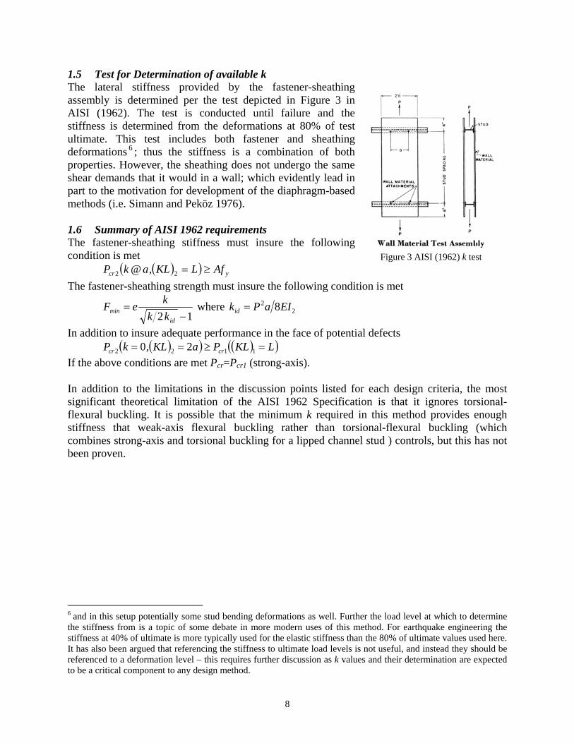
1.5 Test for Determination of available k The lateral stiffness provided by the fastener-sheathing assembly is determined per the test depicted in Figure 3 in AISI (1962). The test is conducted until failure and the stiffness is determined from the deformations at 80% of test ultimate. This test includes both fastener and sheathing deformations 6 ; thus the stiffness is a combination of both properties. However, the sheathing does not undergo the same shear demands that it would in a wall; which evidently lead in part to the motivation for development of the diaphragm-based methods (i.e. Simann and Peköz 1976). 1.6 Summary of AISI 1962 requirements The fastener-sheathing stiffness must insure the following condition is met
( )( ) ycr AfLKL,a@kP ≥=22 The fastener-sheathing strength must insure the following condition is met
12 −=
idmin kk
keF where 22 8EIaPkid =
In addition to insure adequate performance in the face of potential defects ( )( ) ( )( )LKLPaKL,kP crcr =≥== 1122 20
If the above conditions are met Pcr=Pcr1 (strong-axis). In addition to the limitations in the discussion points listed for each design criteria, the most significant theoretical limitation of the AISI 1962 Specification is that it ignores torsional-flexural buckling. It is possible that the minimum k required in this method provides enough stiffness that weak-axis flexural buckling rather than torsional-flexural buckling (which combines strong-axis and torsional buckling for a lipped channel stud ) controls, but this has not been proven.
6 and in this setup potentially some stud bending deformations as well. Further the load level at which to determine the stiffness from is a topic of some debate in more modern uses of this method. For earthquake engineering the stiffness at 40% of ultimate is more typically used for the elastic stiffness than the 80% of ultimate values used here. It has also been argued that referencing the stiffness to ultimate load levels is not useful, and instead they should be referenced to a deformation level – this requires further discussion as k values and their determination are expected to be a critical component to any design method.
Figure 3 AISI (1962) k test
9
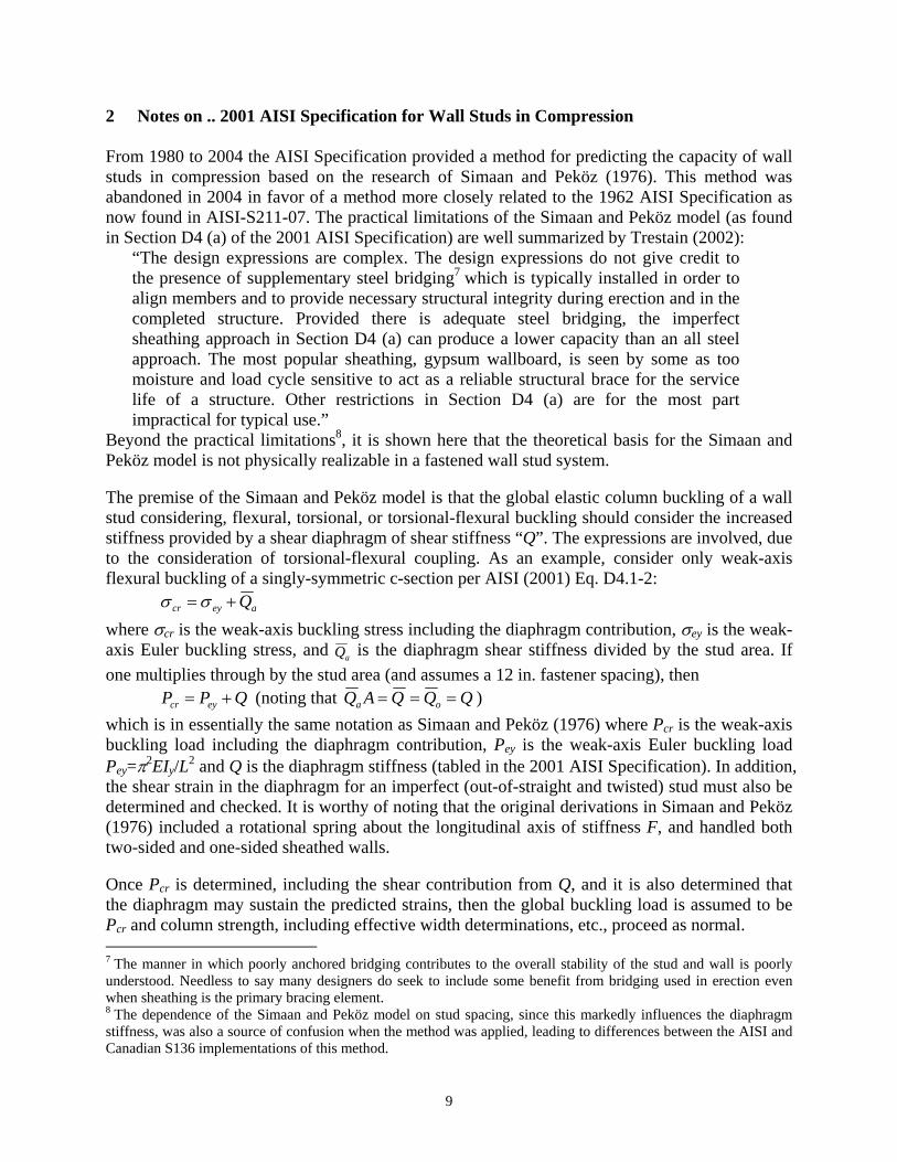
2 Notes on .. 2001 AISI Specification for Wall Studs in Compression From 1980 to 2004 the AISI Specification provided a method for predicting the capacity of wall studs in compression based on the research of Simaan and Peköz (1976). This method was abandoned in 2004 in favor of a method more closely related to the 1962 AISI Specification as now found in AISI-S211-07. The practical limitations of the Simaan and Peköz model (as found in Section D4 (a) of the 2001 AISI Specification) are well summarized by Trestain (2002):
“The design expressions are complex. The design expressions do not give credit to the presence of supplementary steel bridging7 which is typically installed in order to align members and to provide necessary structural integrity during erection and in the completed structure. Provided there is adequate steel bridging, the imperfect sheathing approach in Section D4 (a) can produce a lower capacity than an all steel approach. The most popular sheathing, gypsum wallboard, is seen by some as too moisture and load cycle sensitive to act as a reliable structural brace for the service life of a structure. Other restrictions in Section D4 (a) are for the most part impractical for typical use.”
Beyond the practical limitations8, it is shown here that the theoretical basis for the Simaan and Peköz model is not physically realizable in a fastened wall stud system. The premise of the Simaan and Peköz model is that the global elastic column buckling of a wall stud considering, flexural, torsional, or torsional-flexural buckling should consider the increased stiffness provided by a shear diaphragm of shear stiffness “Q”. The expressions are involved, due to the consideration of torsional-flexural coupling. As an example, consider only weak-axis flexural buckling of a singly-symmetric c-section per AISI (2001) Eq. D4.1-2:
aeycr Q+=σσ where σcr is the weak-axis buckling stress including the diaphragm contribution, σey is the weak-axis Euler buckling stress, and aQ is the diaphragm shear stiffness divided by the stud area. If one multiplies through by the stud area (and assumes a 12 in. fastener spacing), then
QPP eycr += (noting that QQQAQ oa === ) which is in essentially the same notation as Simaan and Peköz (1976) where Pcr is the weak-axis buckling load including the diaphragm contribution, Pey is the weak-axis Euler buckling load Pey=π2EIy/L2 and Q is the diaphragm stiffness (tabled in the 2001 AISI Specification). In addition, the shear strain in the diaphragm for an imperfect (out-of-straight and twisted) stud must also be determined and checked. It is worthy of noting that the original derivations in Simaan and Peköz (1976) included a rotational spring about the longitudinal axis of stiffness F, and handled both two-sided and one-sided sheathed walls. Once Pcr is determined, including the shear contribution from Q, and it is also determined that the diaphragm may sustain the predicted strains, then the global buckling load is assumed to be Pcr and column strength, including effective width determinations, etc., proceed as normal. 7 The manner in which poorly anchored bridging contributes to the overall stability of the stud and wall is poorly understood. Needless to say many designers do seek to include some benefit from bridging used in erection even when sheathing is the primary bracing element. 8 The dependence of the Simaan and Peköz model on stud spacing, since this markedly influences the diaphragm stiffness, was also a source of confusion when the method was applied, leading to differences between the AISI and Canadian S136 implementations of this method.

10
2.1 Design assumptions inherent in Pcr (σcr) Design basis: the strain energy of a diaphragm in shear is added to the conventional strain energy of bending and external work of a stud to form the total potential energy and then used to derive the critical buckling load. This model is mathematically equivalent to assuming the diaphragm provides a rotational spring foundation along the length of the stud. Proof: the derivation for the elastic buckling load of the column and shear diaphragm is provided in Simaan and Peköz (1976) (and Simaan 1973). In particular, the strain energy due to shear distortion in the diaphragm is provided by Eq. (4) of Simaan and Peköz (1976):
( )[ ]∫=L
s dzzQD0
221 α
where Q is the shear rigidity, and α is the shear distortion (angle). The coordinate system employed is provided in Figure 4, where α, the shear distortion angle, is shown to be determined by the rotation of the stud about the y-axis, i.e.
( ) ( ) ( )zdz
zduz yθα ==
Thus, we may re-write the strain energy Ds as
∫=L
ys dzQD0
221 θ
(a) (b) Figure 4 Coordinate system (a) Simaan and Peköz (1976) Fig 2 (b) additional notation
To be slightly more precise u refers to displacement referenced from the shear center. If the sheathing attaches at a point other than the shear center (as it must) then the u at that point is a function of the y location of the attachment and the twist, φ, of the cross-section; but, this is a standard issue for any derivation involving torsional-flexural buckling, and is provided in Simaan and Peköz (1976). What is important about this definition of the strain energy is that it is mathematically identical to the strain energy of a foundation of rotational springs about the y-axis, i.e.:
∫∫ ===L
y
L
ys dzDdzQD0
221
0
221 θβθ αβ
where βα is a foundation of rotational springs as shown in Figure 5. This equivalence is profound because it clarifies that the shear diaphragm model requires that the diaphragm applies a distributed moment along the length to stabilize the stud.

11
Figure 5 Rotational spring model equivalent to shear diaphragm model of Simaan and Peköz (1976)
Discussion: While it is certainly true that the diaphragm undergoes shear, it is equally clear that a discretely fastened diaphragm cannot physically transmit the local moments along the length that would be required for the stud to realize the strain energy Ds as formulated in Simaan and Peköz (1976). Such moments are direct torsional demands on the screw itself and little if any of such demands may be transmitted to the stud. A steel diaphragm welded along the length of the stud may be able to act in this manner9, but not discretely fastened sheathing10. The Simaan and Peköz model, which requires that moments to be transferred from the sheathing, may be directly contrasted with Winter’s model from the 1962 AISI Specification which requires lateral forces to be transferred from the sheathing – even if the lateral forces are themselves derived from the shear resistance of the sheathing. There is still much to be learned from the Simaan and Peköz method: Q is important, torsional-flexural buckling is relevant, one-sided or dis-similar sheathing requires due consideration and modification to the classical torsional-flexural buckling equations, etc. However, it is equally clear that abandonment of the method by AISI in 2004 was justified both practically and theoretically. 2.2 Test for determination of Q The Simaan and Peköz method employed a diaphragm test to determine the shear resistance of the fastener-sheathing combination (see Figure 6). Compared with the “tension” test for determining k in the 1962 Specification the diaphragm test has the advantage of placing both local demands on the fasteners and global shear on the sheathing. Such demands are generally consistent with the expected demands (at least for restricting weak-axis flexure) on both the fastener and sheathing.
9 In fact welded steel diaphragms of corrugated metal formed the experimental basis for the original developers of the shear diaphragm model (i.e., the predecessors to Simaan) 10 It may seem reasonable to assume that pairs of screws can transmit a moment thus negating this argument. However, lateral deformations are required for the screws to act in this manner (and thus lateral springs) but the derivation of Simaan and Peköz intimately requires that a distributed moment be transferred, without that manner in which Q is used in the derivation would have to be fundamentally changed.

12
Figure 6 Details of diaphragm testing reported in Simaan and Peköz (1976)
2.3 Use of Q tests to determine k instead The preceding proof and discussion make it clear that with respect to the stud the lateral restraint provided to the stud, not the moment developed due to the shear deformation is of interest. The lateral stud restraint (k) provided by the fastener-sheathing combination may be derived from the shear diaphragm tests. Two methods are considered here for determining k from shear diaphragm tests: discrete spring and foundation spring, as illustrated in Figure 7.
Figure 7 Lateral spring models for diaphragm test
In both cases moment equilibrium between the diaphragm test and the spring model are achieved. For the discrete spring model the moment equilibrium takes the form:
∑=
Δ=n
iiiit ykPa
2
1
where P is the applied load on the diaphragm, at is the distance to the applied load, ki is the stiffness of each of the 2n fasteners (2 because there are 2 studs with fasteners providing support),
13
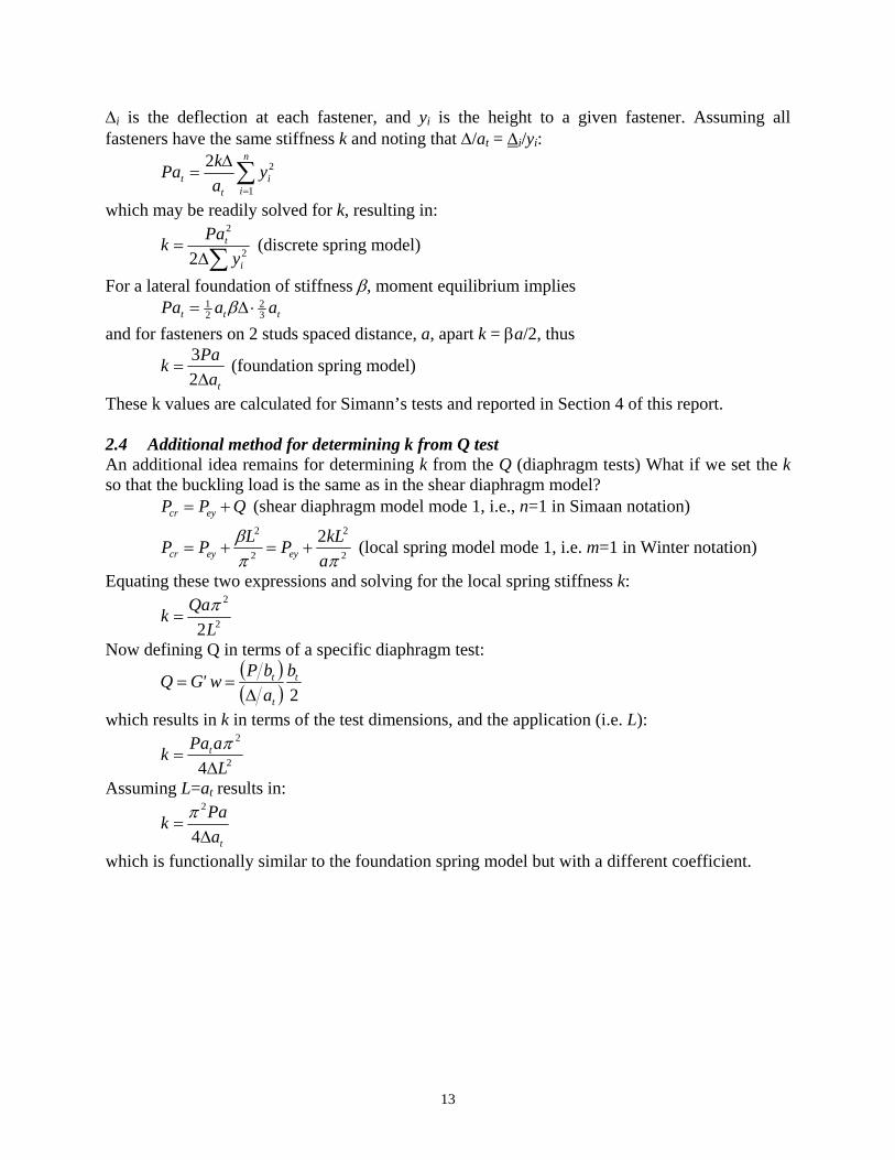
Δi is the deflection at each fastener, and yi is the height to a given fastener. Assuming all fasteners have the same stiffness k and noting that Δ/at = Δi/yi:
∑=
Δ=
n
ii
tt y
akPa
1
22
which may be readily solved for k, resulting in:
∑Δ= 2
2
2 i
t
yPak (discrete spring model)
For a lateral foundation of stiffness β, moment equilibrium implies ttt aaPa 3
221 ⋅Δ= β
and for fasteners on 2 studs spaced distance, a, apart k = βa/2, thus
taPakΔ
=23 (foundation spring model)
These k values are calculated for Simann’s tests and reported in Section 4 of this report. 2.4 Additional method for determining k from Q test An additional idea remains for determining k from the Q (diaphragm tests) What if we set the k so that the buckling load is the same as in the shear diaphragm model?
QPP eycr += (shear diaphragm model mode 1, i.e., n=1 in Simaan notation)
2
2
2
2 2ππ
βakLPLPP eyeycr +=+= (local spring model mode 1, i.e. m=1 in Winter notation)
Equating these two expressions and solving for the local spring stiffness k:
2
2
2LQak π
=
Now defining Q in terms of a specific diaphragm test: ( )( ) 2
t
t
t babPw'GQ
Δ==
which results in k in terms of the test dimensions, and the application (i.e. L):
2
2
4 LaPak t
Δ=
π
Assuming L=at results in:
taPakΔ
=4
2π
which is functionally similar to the foundation spring model but with a different coefficient.

14
3 Notes on… 2007 AISI-COFS Specification for Wall Studs in Compression Currently the design of wall studs in compression may follow AISI-S211-07 the “Wall Stud Design” standard. AISI-S211-07 defines two methodologies for the design: “all-steel design” and “sheathing braced design”. All-steel design ignores the sheathing contribution and thus is not the focus of this discussion. The general requirements for sheathing braced design are provided in B1(b) of AISI-S211-07:
“Wall stud assemblies using a sheathing braced design shall be designed assuming that identical sheathing is attached to both sides of the wall stud and connected to the bottom and top horizontal members of the wall to provide lateral and torsional support to the wall stud in the plane of the wall. Wall studs with sheathing attached to both sides that is not identical shall be designed based on the assumption that the weaker of the two sheathings is attached to both sides.”
In addition the sheathing must be identified as a structural element in the drawings and a construction load combination must be checked without the sheathing in place. The specific requirements that must be checked are provided in B1.2 of AISI-S211 and state that “Both ends of the stud shall be connected to restrain rotation about the longitudinal stud axis and horizontal displacement perpendicular to the stud axis.” Further, in B1.2(b) it is prescribed that the global buckling load of a stud, with fasteners spaced distance “a” apart shall be determined ignoring any sheathing contribution (i.e. k = 0) over a distance of 2a, i.e.:
( ) ( ) ( )( )aKL,aKL,LKL,kP tyxcr 220 ==== If the sheathing is gypsum wall board (GWB) on both sides of the studs B2.1(b) also provides prescriptive maximum nominal axial capacities based on the use of 1/2 in. or 5/8 in. GWB and No. 6 or No. 8 screws spaced such that a < 12 in. In addition, AISI-S211 provides significantly more guidance in the commentary. Sheathing braced design was dropped from the main AISI Specification (AISI-S100) in 2004, thus design of a sheathed stud defaults to the general rational analysis clause of AISI-S100 section A. The AISI-S211 commentary thus provides a rational method, but since the guidance is in the commentary and not the main body of AISI-S211 it is just one possible, not the only, method. The commentary states that the bracing force at the fasteners should be designed for 2%P (where P is the axial load in the stud) and that failure in the sheathing material should also be checked, but screw-to-stud capacity or screw capacity in shear need not be checked. 3.1 Design assumptions related to use of identical or weaker-of-the-two sheathing (B1(b)) The provision requiring sheathing on both flanges and when dis-similar consideration of only the weaker-of-the-two sheathing types is well explained in the AISI-S211 commentary.
“Although the design approach for sheathing braced design is based upon engineering principals, the standard limits the sheathing braced design to wall
Figure 8 Stud and typical coordinates

15
stud assemblies assuming that identical sheathing is attached to both sides of the wall stud. This limit recognizes that identical sheathing will aid in minimizing the twisting of the section. If only single sided sheathing is used, additional twisting of the section will occur thus placing a greater demand on the sheathing; therefore, the stud must be designed and braced as an all steel assembly. The provision that wall studs with sheathing attached to both sides that is not identical shall be permitted to be designed based on the assumption that the weaker of the two sheathings is attached to both sides is based on engineering judgment. Determination of which of the two sheathings is weaker shall consider the sheathing strength, sheathing stiffness and sheathing-to-wall stud connection capacity, as applicable.”
3.2 Design assumptions inherent in determining global buckling load Pcr It is assumed that the sheathing provides enough stiffness that Pcr ignoring the sheathing over a length equal to twice the fastener spacing, a, is always less than Pcr considering the sheathing:
( ) ( ) ( )( ) ( ) ( ) ( )( )LKLKLKL,a@kPaKL,aKL,LKL,kP tyxcr
assumed
tyxcr ===<==== 220 This assumption is not mathematically valid, as k 0 the right hand side will be less than the left hand side by definition. One may assume that for practical k and a that this is not the case, but k values in some cases can be quite low. 3.3 Comparison of AISI 2007 (S211-07) with 1962 AISI Specification w.r.t Pcr Recognizing that Pcr for a singly-symmetric lipped channel (the typical stud) is either Pcry (weak-axis buckling) or PcrTF (torsional-flexural buckling) the above assumption may also be stated as: min ( )( )aKL,kP ycry 20 ==
( ) ( )( )aKL,LKL,kP txcrTF 20 ===
assumed<
min ( )( )LKL,a@kP ycry = ( ) ( )( )LKL,a@k;LKL,kP txcrTF === 0
The origin of the design check for a ‘defective fastener’ and thus the 2a unbraced length is the 1962 AISI Specification. However, the way in which this hypothetically defective fastener in a sheathed stud wall is used to check the capacity is very different. In the following table the basic design checks of AISI 2007 and AISI 1962 are contrasted:
Table 1 Partial comparison of AISI 2007 (S211-07) and AISI 1962 AISI 2007 (S211-07) AISI 1962
( )crTFcrycr P,PminP = where
( )( )aKL,kP ycry 20 == ( ) ( )( )aKL,LKL,kP txcrTF 20 ===
and 2%P for fasteners
( )( )LKLPP xcrxcr == * subject to
( )( ) ( )( )LKLPaKL,kP xcrxycry =≥== 20 ( )( ) yycry AfLKL,a@kP ≥=
and ~2%P for fasteners
* It is important to note that AISI 1962 did not include torsional-flexural buckling and PcrTF<Pcrx though as torsional resistance is increased PcrTF will asymptote to Pcrx.

16
The obvious difference is that AISI 2007 is more of an “analysis” method in that it attempts to provide the capacity regardless of how the member fails, while the AISI 1962 is a more “prescriptive” method where the limit state (Pcr=Pcrx) has been pre-selected and the provisions are intended to insure that k and a are selected such that this limit state does occur. The end result of the AISI 1962 provisions is that k must be greater than a minimum amount, and a must be less than a maximum amount. The 1962 check for a defective fastener at 2a in intended to insure that a is less than one estimate of a practical maximum for a, but the strength of the stud is governed by Pcrx. This is different than the 2007 methodology that assumes buckling of the stud occurs over a 2a unbraced length. While it is only a matter of opinion, to this writer, the argument that consideration of a defective fastener should be used to determine a maximum fastener spacing (the 1962 approach) seems more reasonable than assuming the strength of the stud should be derived from the artificial consideration of a defective fastener (as in the 2007 method). 3.4 Design assumptions related to member end conditions B1.2 of AISI-S211-07 states that “Both ends of the stud shall be connected to restrain rotation about the longitudinal stud axis and horizontal displacement perpendicular to the stud axis.” How this is completed, whether standard details provide it, and what this implies in terms of effective length (K) factors is not definitively established. However, since no global buckling check is typically performed (only the check between fasteners) the use of this provision is not fully realized. In compression testing of studs sheathed with gypsum board on both sides, as reported e.g. in Lee and Miller (2001), specific K factors were prescribed:
“All of these 2.44 m (8 ft) height wall assemblies, sheathed with 16 mm (5/8 in.) thick gypsum board, were tested with the base assumed fixed and the top pinned about the strong axis of the stud (Kx = 0.7), with both the base and the top assumed fixed about the weak axis of the stud (Ky = 0.5), and with rotation assumed restrained at both ends with warping restrained at the base and unrestrained at the top (Kt = 0.7).”
A better understanding of appropriate K factors for standard details is needed. The issues are difficult to separate from the rest of the design assumptions; for example, ignoring end eccentricities may be adequate when K = 1 is employed, but if more exact K values are considered then greater effort to understand the eccentricities and load path may be necessary. With respect to load path, the 1/8 in. end gap at the end of a stud creates a complicated end condition, where first screw shear and then later stud-to-track bearing provide the end resistance. These two modes obviously provide different levels of resistance (and eccentricity for the stud). 3.5 Discussion of commentary application of 2% rule for fasteners The commentary of AISI-S211-07 states that a rational analysis of the local demands on the fastener-sheathing assembly is 2%P, and cites Winter (1960). The old “2% rule” is long familiar to engineers. However, this statement is somewhat incomplete, and brief consideration of the typical derivation as provided below in Figure 9 shows that (a) the force in the brace is strongly a function of the stiffness of the brace, and (b) for a brace with the now typically assumed twice the ideal stiffness the required brace force is 1%P or 0.01P. We may use factors of safety or other arguments to turn the result back to 2%P, but the more important observation of the preceding two is that the brace force is a function of the brace stiffness and if the brace stiffness

17
is high braced forces are lower than 2%P, but if the brace stiffness is low brace forces can be well in excess of 2%P! (You only get low brace forces when you provide enough brace stiffness.)
*Note the equation in the commentary is in error the brace force is kΔ, not k(Δ+Δo)
Figure 9 Classic derivation of Winter’s bracing force (and stiffness) model 3.6 Equivalence between 2007 cited Winter model and 1962 Specification This simple model may be shown to be equivalent to that used by Winter in the 1962 Specification (before his empirical modifications see discussion in that section). In fact:

18
3.7 Winter’s prediction for the role of fastener spacing (getting beyond the 2% rule) The preceding expression is identical to that developed and provided in the discussion of the 1962 Specification presented earlier, namely:
actid
idmin kk
keF−
=12 and 2
2 8EIaPkid =
But, the ideal stiffness is defined for weak-axis buckling in a more productive manner in the 1962 Specification such that fastener spacing, a, and weak-axis stiffness EI2 are made immediately relevant to the brace force prediction. That is, tighten your fastener spacing up and your brace forces go down – something not so obviously available using a blanket 2% rule. 3.8 Summary of findings w.r.t the application of 2% rule in AISI-S211-07 Commentary Use of the 2% rule requires the application of a minimum stiffness, or the more general expressions could be employed to determine the required bracing force given the supplied stiffness. Currently it is assumed the stiffness is provided. Fastener demands due to torsion are not addressed in the preceding, nor by the 2% rule. The basic methodology holds, but cross-section location of the fastener matters as the fastener distance from the shear center generates lateral forces under twist that the fastener must sustain. These forces may add or subtract from the forces required to laterally restrain the stud. 3.9 Given fastener demands, what to check? The AISI-S211 commentary recommends that “screw-to-stud capacity or screw capacity in shear need not be checked” and instead failure (typically in bearing) is the assumed mode of failure. Perhaps this is universally true, but it is not immediately obvious. 3.10 Discussion of Gypsum wall board provisions The provisions in AISI-S211-07 are intended to insure that the axial load capacity of a stud braced by gypsum wall board on both sides is never greater than ½ the experimentally observed load in a limited number of tests. This is achieved by determining the demand per fastener in the available tests using the 2% rule and enforcing that calculated demands are never greater than ½ that value.
19
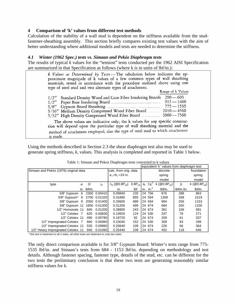
4 Comparison of ‘k’ values from different test methods Calculation of the stability of a wall stud is dependent on the stiffness available from the stud-fastener-sheathing assembly. This section briefly compares existing test values with the aim of better understanding where additional models and tests are needed to determine the stiffness. 4.1 Winter (1962 Spec.) tests vs. Simaan and Peköz Diaphragm tests The results of typical k values for the “tension” tests conducted per the 1962 AISI Specification are summarized in that Specification as follows (where k is in units of lbf/in.):
Using the methods described in Section 2.3 the shear diaphragm test also may be used to generate spring stiffness, k, values. This analysis is completed and reported in Table 1 below.
Table 1: Simaan and Pekoz Diaphragm tests converted to k values equivalent 'k ' values from diaphragm test
Simaan and Peköz (1976) original data calc. from orig. data discrete foundationa t =b t =24 in. spring spring
model modeltype a G' γd Δd (@0.8Pult) 0.8Pult at Σyi
2 k (@0.8Pult) β k (@0.8Pult)in. lbf/in. in. lbf in. in.2 lbf/in. lbf/in./in. lbf/in.
5/8" Gypsum 6 2300 0.00410 0.09840 226 24 756 876 288 8635/8" Gypsum* 9 2700 0.01320 0.31680 855 24 594 1309 338 15193/8" Gypsum 9 2050 0.01400 0.33600 689 24 594 994 256 11533/8" Gypsum 11 1600 0.01300 0.31200 499 24 674 684 200 1100
1/2" Homosote 11 845 0.01200 0.28800 243 24 674 361 106 5811/2" Celotex 7 620 0.00830 0.19920 124 24 530 337 78 2711/2" Celotex 11 490 0.00780 0.18720 92 24 674 209 61 337
1/2" Impregnated Celotex 7 660 0.00960 0.23040 152 24 530 359 83 2891/2" Impregnated Celotex 11 530 0.00860 0.20640 109 24 674 226 66 364
1/2" Heavy Impregnated Celotex 11 940 0.01060 0.25440 239 24 674 402 118 646* this test is fastened on all 4 sides, all other tests are fastened on only two sides The only direct comparison available is for 3/8” Gypsum Board: Winter’s tests range from 775-1535 lbf/in. and Simaan’s tests from 684 - 1153 lbf/in. depending on methodology and test details. Although fastener spacing, fastener type, details of the stud, etc. can be different for the two tests the preliminary conclusion is that these two tests are generating reasonably similar stiffness values for k.

20
4.2 Comparison of k values from other tests Miller and Peköz (1994) reported on 10 gypsum board tests conducted using the same basic setup as the Winter tests from the AISI 1962 Specification. Fiorino et al. (2006) recently reported on a reasonably large series of tests on gypsum board and OSB completed in a style similar to those reported in the AISI 1962 Specification11. The test setup in Fiorino et al. (2006) provides greater stiffness to the studs and concentrates the deformations more specifically at the fastener locations. In both the Miller and Peköz (1994) and Fiorino et al. (2006) tests edge distance was specifically studied, in addition the failure mode in the tests was not always bearing of the sheathing, but included screw shear and other limit states. Note, relatively recently Lee working with Miller at Oregon State completed additional testing, this data has been requested by the authors (from Lee’s thesis) and will be evaluated when it becomes available. Comparison of available data is provided in Table 2.
Table 2: Comparison of local stiffness measurements Gypsum Board tests k (lbf/in.) at 80% ult.
min max3/8" Winter as reported in AISI 1962 Specification 775 15353/8" Simaan and Pekoz (1976) converted to k per Section 2.3 of this report 684 11535/8" Simaan and Pekoz (1976) converted to k per Section 2.3 of this report 863 15195/8" Miller and Pekoz (1994) 850 31861/2" Fiorino et al. (2006) 1124 5733 Oriented Strand Board tests k (lbf/in.) at 80% ult.
min max3/16" "Medium Density Compressed Wood Fiber Board" Winter 1962 Spec. 2010 45605/16" "High Density Compressed Wood Fiber Board" Winter 1962 Spec. 3960 75603/8" Fiorino et al. (2006) 1967 7250 Table 2 shows that the original test ranges provided by Winter in the 1962 Specification are still useful and relevant today. In addition when examined in detail the data provide valuable stiffness ranges for studies related to bracing of studs by sheathing. Comparison of these available stiffness values with typically required stiffness values (to keep brace forces low) is needed. 4.3 Additional discussion of local fastener k tests Fastener-sheathing assemblies provide stiffness and must have ample strength. Existing data (particularly Fiorino et al. 2006) provides information on the strength in addition to the stiffness that could be utilized in design. Models which separate the stiffness components are needed so that results of the local stiffness tests may be properly generalized for use in stability models as braces. In particular the effect of fastener size, sheathing thickness, edge distance, etc. needs to be more specifically quantified (or at least tabled) so that engineers can determine where in the relatively large ranges of Table 2 their particular situation lies. The 1962 Specification advised the use of the secant stiffness at 80% of ultimate value. This measure of stiffness has a significant impact on the assumed stiffness in any bracing model. In 11 Actually the design values for the tests are reported in the “Supplementary information: in the 1962 AISI Design Manual, and not the Specification proper.
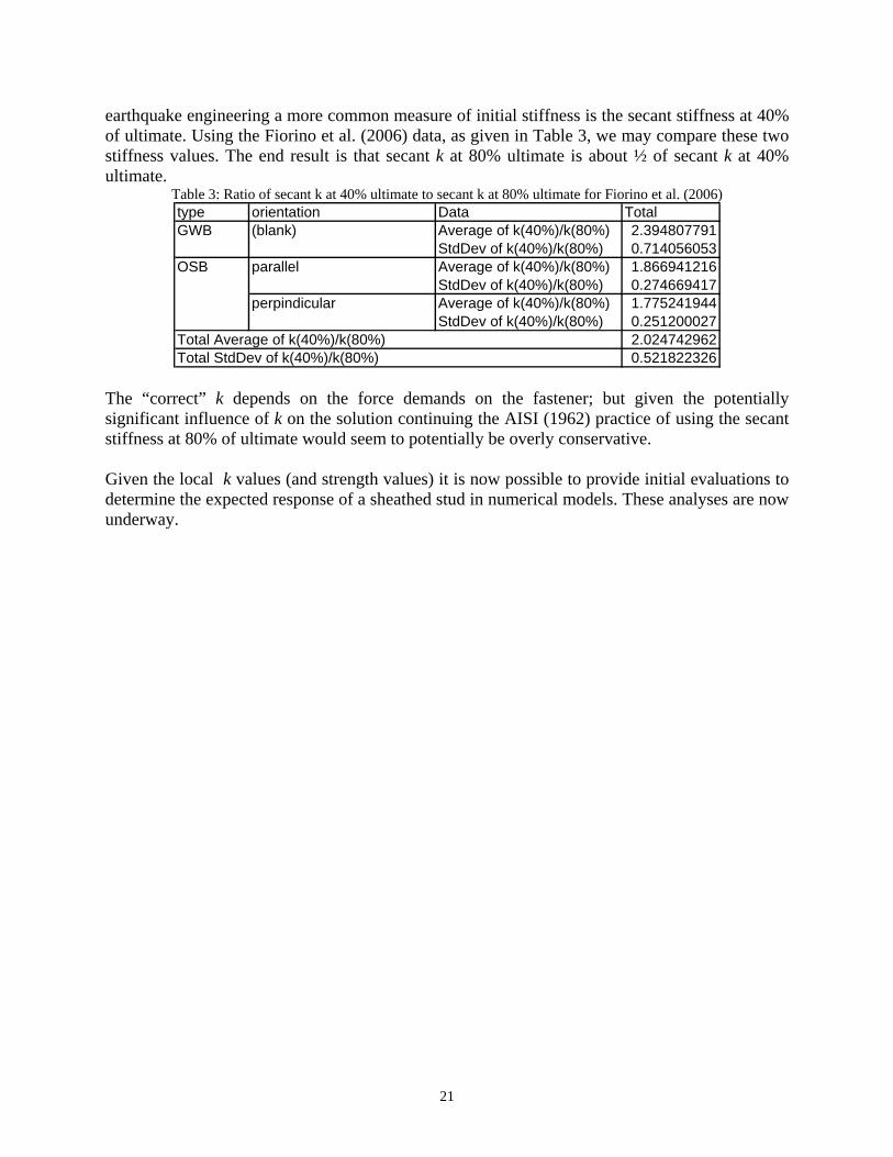
21
earthquake engineering a more common measure of initial stiffness is the secant stiffness at 40% of ultimate. Using the Fiorino et al. (2006) data, as given in Table 3, we may compare these two stiffness values. The end result is that secant k at 80% ultimate is about ½ of secant k at 40% ultimate.
Table 3: Ratio of secant k at 40% ultimate to secant k at 80% ultimate for Fiorino et al. (2006) type orientation Data TotalGWB (blank) Average of k(40%)/k(80%) 2.394807791
StdDev of k(40%)/k(80%) 0.714056053OSB parallel Average of k(40%)/k(80%) 1.866941216
StdDev of k(40%)/k(80%) 0.274669417perpindicular Average of k(40%)/k(80%) 1.775241944
StdDev of k(40%)/k(80%) 0.251200027Total Average of k(40%)/k(80%) 2.024742962Total StdDev of k(40%)/k(80%) 0.521822326
The “correct” k depends on the force demands on the fastener; but given the potentially significant influence of k on the solution continuing the AISI (1962) practice of using the secant stiffness at 80% of ultimate would seem to potentially be overly conservative. Given the local k values (and strength values) it is now possible to provide initial evaluations to determine the expected response of a sheathed stud in numerical models. These analyses are now underway.

22
5 Design of a sheathed wall stud in compression The following is an attempt to define the known demand and capacity/limit states for a sheathed cold-formed steel wall stud. Not all demands or capacity/limit states are necessarily checked explicitly in design, but the attempt here is to make an exhaustive list to understand what we know and do not know to the maximum extent possible. Although the focus is on sheathing braced design, if construction loads are considered without the sheathing in place then all-steel design must be examined as well. 5.1 Demand Each limit states/capacities must be compared to a demand to determine if the designed wall stud system is adequate. In some cases explicit calculation of these demands will not be required given some control on imperfections and minimum stiffness of components is exercised. The attempt here is to try to characterize the known demands as best we can at this stage, Stud demands Essentially here the issue is just the axial load12, though one must think this through as additional first-order moments may exist if load path to get the load into the stud essentially creates a load eccentricity (i.e., applied load not at the centroid). In addition, bending moments that develop due to P-δ and P-Δ imperfections are real and need to be considered in some fashion. Of particular concern is the potential for out-of-alignment in the framing to create large eccentricities in the axial demand. Whether this should be treated as a column (in the manner of P-δ and P-Δ) or as direct beam-column design is an open question.13 Finally, thinking about gypsum sheathed walls and noting that AISC has fire analysis provisions, do we need fire scenario/load combination?14 and an additional P to be considered in that case? (P) Axial load on the stud Construction load combination without sheathing in place give one estimate of P Ultimate load combinations with sheathing in place give another estimate of P Stud-fastener sheathing demands This may be viewed essentially as a bracing problem where forces develop in the fasteners due to the magnitude of the initial imperfection and the stiffness of the brace. Given a minimum stiffness requirement it may be possible to greatly simplify these demand calculations. The forces that develop include the following: (VF) Lateral forces on the connection (stud-fastener-sheathing)
Developed to restrict global buckling due to bow imperfections and weak-axis flexural buckling due to twist imperfections and torsion demands in TF buckling
(potentially increased substantially for dis-similar sheathing as well)
12 This work addresses only the demands for an axially loaded stud (or wall). Additional demands are developed as companions to these when the stud must also resist direct bending, or the stud is a chord stud in a shear wall where it must resist collected shear forces. These issues will be addressed in the future. 13 For now, the focus remains on in-line framing and the assumption that this end eccentricity is not a primary issue, but this must be maintained through proper tolerances on the in-line framing requirements – otherwise direct beam-column analysis (treating the P⋅e moment as a direct bending demand) should be required. 14 Direct fire analysis remains as a future research issue, and will not be addressed further in this note/research.
23
due to camber imperfections and TF buckling (ignore?) Developed to restrict distortional bucking due to lateral component of DB (usually ignored) Impact on fasteners of load location (at the flanges, vs. at the centroid etc) needs study
(TF/CF) Tension/compression forces on the connection (stud-fastener-sheathing) Developed to restrict global buckling
when restricting torsion in the plane of the cross-section Developed to restrict distortional buckling when restricting torsion of the connected flange Stud-to-track demands (i.e. at top and bottom of stud) This is again, a bracing problem where stiffness and imperfections largely determine the demands on the assembly. Here design usually makes a specific assumption about end conditions, that assumption leads to minimum stiffness requirements which potentially simplify the demand calculations. A significant temptation exists to assume this is not a critical connection (low demand, plenty of capacity). A significant complication at this location is the 1/8” end gap tolerance which allows the stud-to-track demands to begin entirely in the connectors and then after closing the gap migrate to direct bearing. (VF) Lateral forces on the connection developed to restrict sway mode of stud, sensitive to story out-of-straightness (P-Δ) developed to restrict torsion at member ends, sensitive to twist imp.? (TF/CF) Tension/compression forces on the connection developed to restrict torsion at member ends, sensitive to twist imp.? Track-fastener-sheathing demands (i.e., along the top/bottom of wall) Whether or not this is part of the stud design is not exactly clear, but the presence of track-fastener-sheathing connectors changes boundary conditions on the sheathing and stiffens its response. Demands in this connector should be a function of shear in the sheathing, but specifics of this calculation are not developed at this time.
(VF, TF/CF) how to best calc. these demands? Sheathing demands Failure of the sheathing can occur away from the connectors. To check this one would consider the resultant shears and moments developed from the connectors. (VS) Shear in the sheathing Developed to restrict weak-axis flexural buckling (MS) Moment on the sheathing Developed in restriction of torsion, and strong-axis buckling Developed in restriction of distortional buckling Track demands Out-of-alignment for in-line framing is a potentially significant bending moment on the track, but this is not a focus for the wall stud. The wall stud must be supported from in-the-plane-of-the-wall sway at the top and bottom which creates an axial force on the track, and from twist at the top and bottom of the stud which creates a bending moment on the track and from out-of-the-plane-of-the-wall rotation which creates a torsion on the track. However the track acts essentially

24
as a bracing member so if adequate stiffness is provided these demands should all be low. Generally we assume more than adequate stiffness is available in a common system, the actual amount is not known. Bridging demands This is again essentially a bracing problem where stiffness and imperfections determine the force demands on the bridging and the bridging-fastener-clip-fastener-stud assembly. How bracing demands are shared when both bridging and sheathing are in place needs further study. Torsion demands have not been examined in real detail either. 5.2 Capacity/Limit States Please note, not all limit states necessarily will be checked in typical design, the attempt here is to list known limit states to focus the research efforts.

25
Summary of Limit States for a Sheathed Wall Stud in Compression
Component Predictive Status as of January 2008
Stud (Sheathing based design under ultimate loads)
Local-global interaction (i.e. in AISI Pn=AeffFn) AISI-S100-07 C4 and Appendix 1 provides methodology
Global buckling (F, T, FT) including sheathing
If fastener-sheathing stiffness and sheathing stiffness known then classical equations may be derived or FSM used to get elastic buckling values. Existing classical equations are too limited (Winter 1960) or include unrealistic mechanical assumptions (Simaan and Peköz 1976). Some more recent papers with classical equations exist, but they are not practical for everyday use. Alternatives include (a) implement computationally, or (b) create rules a la 1962 Spec. to force a given limit state. Can bridging be included to? Why not?
Should the stud be checked assuming a defective fastener?
This is under numerical investigation now. Perhaps a reduced stiffness from the fasteners or other methods to reflect the system effect are favored. A maximum fastener spacing a la 1962 Spec. may alleviate this issue to a great extent.
Local buckling (probably ignoring sheathing contribution)
Generally felt that sheathing provides little increase to local buckling of studs, because lipped channel local buckling is largely dominated by web local buckling, first cut would continue to ignore the sheathing in local buckling calculations. Studs typically have holes, provisions of AISI-S100-07 provide for this reduction.
Distortional buckling (ignoring sheathing/including sheathing)
AISI-S100-07 C4.2 provides methodology, for fastener-sheathing rotational stiffness Schafer et al. (2007) testing provides useable stiffness values and recent CFSEI Tech Note (currently under review) provides practical method of implementation for floor joists. Extensions to wall studs are needed. Can bridging be included to? Why not?
Should the stud be checked assuming a defective fastener?
Current inclination is to say no, any one problematic fastener should have relatively low influence on the result. Further, current testing methods conservatively ignore that the fastener demands vary along the length and instead enforce a constant demand. Pilot testing with missing/defective fasteners underway. Numerical analysis can be conducted.

26
Stud-fastener-sheathing connection
Fastener only (screws) (Note, fastener failure is not a typically expected limit state)
shear AISI-S100-07 says per manufacturer table or test tension AISI-S100-07 says per manufacturer table or test shear + tension No AISI-S100-07 provisions, AISI expressions for
bolts could provide a rational engineering analysis extension.
Assembly (stud-fastener-sheathing) shear – Tilting AISI-S100-07 Eq. E4.3.1-1 (tilting) should
probably be checked even though original research was likely steel-steel for t1 and t2
shear – Bearing
AISI-S100-07 E4.3.1 provides bearing equations for steel alone NDS-2005 11.3.2-4 provides bearing equations for wood alone, including plywood alone and OSB alone APA E830D provides a limited set of values for plywood-to-steel Gypsum? (some values in literature? use local stiffness tests? some ASTM E75 tests in GA-229-08 could perhaps be converted for use)
shear – Edge tear out AISI-S100-07 E4.3.2 for steel tear out NDS 11.5 defines min. edge distance for wood Edge tear out for Plywood, OSB, Gypsum? (some values in lit.)
tension - pull-out (withdrawal)
AISI-S100-07 E4.4.1 for steel pull-out NDS-2005 11.2.2 for wood screws in wood, specific gravity values for OSB and plywood from bearing check (11.3.2) exist APA E830D provides a limited set of values for plywood-to-steel and does not distinguish between pull-out and pull-through AP ATT-051A-2007 provides a preliminary method for convert-ing plywood values for use with OSB. Gypsum? (some values for nails in GA-235-05)
tension - pull-through (pull-over)
AISI-S100-07 E4.4.2 provisions are for pull-over through steel so these are not applicable as sheathing is on the outside not steel. APA E830D provides a limited set of values for plywood-to-steel and does not distinguish between pull-out and pull-through NDS does not appear to provide any guidance? OSB? Gypsum?
shear + tension (lateral and withdrawal) NDS-2005 11.4 provides reduced lateral capacity (reduced withdrawal?) for screws with tension as well as shear, in wood

27
Track-fastener-sheathing connection
Fastener
fastener only strength is independent of assembly, so the method is the same as the fastener only checks for stud-fastener-sheathing connection.
Assembly
same capacity calculations states as stud-sheathing-connection but replace track for stud, also different demands of course.
Stud-to-track-fastener-sheathing connection
This section requires revision BWS April 2008 – revise to only be stud-to-track check….
Fastener
fastener only strength is independent of assembly, so the method is the same as the fastener only checks for stud-fastener-sheathing connection.
Assembly
extra layer of steel potentially complicates calculation
shear-tilting: existing AISI-S100 does not apply shear-bearing: steel alone and wood alone only values only available shear-edge tear out: no change from stud-fastener-sheathing tension-pull-out: existing values very conservative tension-pull-through: little guidance available shear+tension: little guidance available
One presumes that the engineer may desire to assume that the addition of the layer of steel (the track) strengthens the assembly such that it never controls – the primary complications with such logic is that end fasteners may have greater demands – this needs further investigation.
Sheathing
Shear APA 2004 Panel Design Specification provides allowable stresses for plywood and OSB in shear these could be converted and used. GA 229-08 could be used for gypsum, but they are governed by the fastener failure in gypsum, not the gypsum material itself, such a failure should really be picked up at the connection not for the whole panel.
Bending APA 2004 Panel Design Specification provides allowable stresses for plywood and OSB in shear these could be converted and used. GA 235-05 provides strength values for Gypsum
28
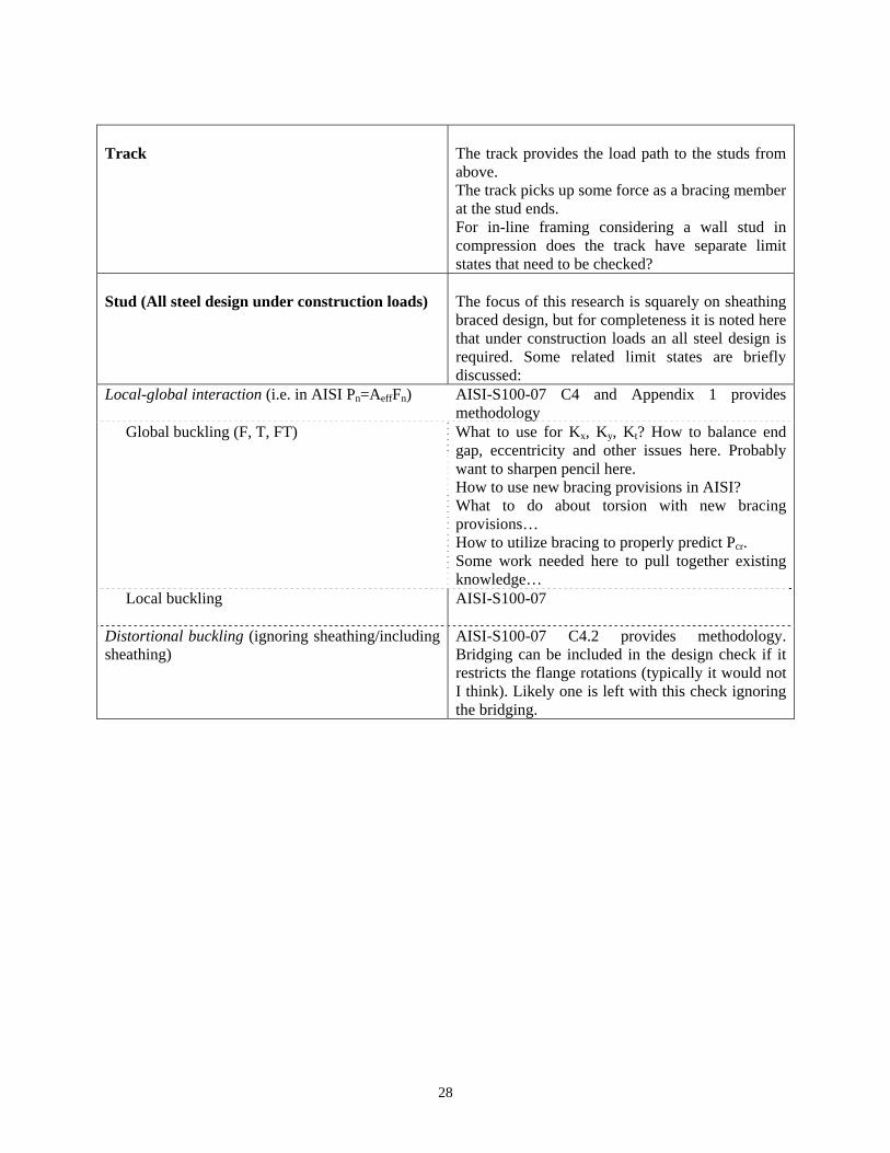
Track
The track provides the load path to the studs from above. The track picks up some force as a bracing member at the stud ends. For in-line framing considering a wall stud in compression does the track have separate limit states that need to be checked?
Stud (All steel design under construction loads)
The focus of this research is squarely on sheathing braced design, but for completeness it is noted here that under construction loads an all steel design is required. Some related limit states are briefly discussed:
Local-global interaction (i.e. in AISI Pn=AeffFn) AISI-S100-07 C4 and Appendix 1 provides methodology
Global buckling (F, T, FT)
What to use for Kx, Ky, Kt? How to balance end gap, eccentricity and other issues here. Probably want to sharpen pencil here. How to use new bracing provisions in AISI? What to do about torsion with new bracing provisions… How to utilize bracing to properly predict Pcr. Some work needed here to pull together existing knowledge…
Local buckling
AISI-S100-07
Distortional buckling (ignoring sheathing/including sheathing)
AISI-S100-07 C4.2 provides methodology. Bridging can be included in the design check if it restricts the flange rotations (typically it would not I think). Likely one is left with this check ignoring the bridging.

29
Bridging
Under construction loads with no sheathing in place
Bridging alone Clip alone Bridging-fastener-clip-fastener-stud connection
Bridging-to-clip fastener (weld) Clip-to-stud fastener (weld)
This is a conventional all-steel design, but still the number of required checks is significant. Further, accurate determination of the demands is non-trivial and dependent on assumed global imperfections, etc. Collection of bracing forces may be beyond the ‘wall stud’ design but for the bridging it needs to be considered, and therefore cannot be wholly ignored, including providing anchorage that has the necessary strength and stiffness to allow the bridging to work.
At ultimate loads with sheathing in place Bridging alone Clip alone Bridging-fastener-clip-fastener-stud connection
Bridging-to-clip fastener (weld) Clip-to-stud fastener (weld)
Bridging and the associated clip are designed under construction loads, but are present during ultimate loads. Forces in the bridging should be greatly decreased with the presence of the sheathing and it may be appropriate to ignore these limit states based on inspection. However, real challenges remain on the demand side to get the load sharing between the sheathing and the bridging accurately enough to be able to responsibly investigate these limit states.
Some over-arching issues for sheathing based design that need further study… How to incorporate load duration effects which are a large part of NDS Specification? How to incorporate moisture sensitivity which plays a significant role particularly for gypsum? How to incorporate sensitivity to cycled loads, particularly for gypsum?

30
6 References AISC (2005). Specification for Structural Steel Buildings, American Institute of Steel
Construction, Chicago, IL. AISI (1962). Light Gage Cold-Formed Steel Design Manual. American Iron and Steel Institute,
New York, NY (now Washington, D.C.) AISI (2007). North American Standard for Cold-Formed Steel Framing–Wall Stud Design.
AISI-S211-07, American Iron and Steel Institute, Washington, D.C.. APA (2005). “Fastener Loads for Plywood – Screws.” APA The Engineered Wood Association,
Tacoma, Washington. E830D. APA (2007). “Screw withdrawal from APA-trademarked OSB.” APA The Engineered Wood
Association, Tacoma, Washington. TT-051A. Fiorino, L., Della Corte, G., Landolfo, R. (2006) “Experimental tests on typical screw
connections for cold-formed steel housing.” Eng. Struct., doi:10.1016/j.engstruct.2006.09.006
Gypsum Association (2005). “Gypsum Board Typical Mechanical and Physical Properties.” Gypsum Association, Washington, D.C., GA-235-05b.
Gypsum Association (2008). “Shear Values for Screw Application of Gypsum Board on Walls.” Gypsum Association, Washington, D.C., GA-229-08.
Lee, Y., Miller, T.H. (2001). “Axial Strength Determination for Gypsum-Sheathed, Cold-Formed Steel Wall Stud Composite Panels.” ASCE, Journal of Structural Engineering. 127 (6) 608-615.
Miller, T., Peköz, T. (1994). “Behavior of Gypsum-Sheathed Cold-Formed Steel Wall Studs.” ASCE, Journal of Structural Engineering. 120 (5) 1644-1650.
NDS (2005). National Design Specification for Wood Construction. American Forest & Paper Association, American Wood Council, Washington, D.C.
Simaan, A, (1973). “Buckling of Diaphragm-Braced Columns of Unsymmetrical Sections and Application to Wall Studs Design.” Ph.D. Dissertation, Cornell University, Ithaca, NY.
Simaan, A. Peköz, T. (1976). “Diaphragm Braced Members and Design of Wall Studs.” ASCE, Journal of the Structural Division, 102 (ST1) 77-92.
Trestain, T. (2002) AISI Cold-Formed Steel Framing Design Guide CF02-1, American Iron and Steel Institute, Washington D.C.
Winter, G. (1960). “Lateral Bracing of Beams and Columns.” ASCE Transactions, Paper No. 3044, per footnote “published in 1958 in the Journal of the Structural Division essentially as is”.