notes on assembling and using the mini pearl...
TRANSCRIPT

Page 1 of 5
Notes on assembling and using the Mini Pearl Logger
Assembly
The three primary boards of the logger kit have some male headers (pins) soldered on. Loose headers
are included for the Arduino Pro Mini, but these are optional. To connect the boards, wires can be
soldered to the header pins or directly to the holes in the Pro Mini. Some holes in the Pro Mini (VCC and
GND) must have more than one wire soldered to them. Wires can be twisted together and passed
through a single hole for soldering, but three wires are easier to connect if a header pin is present. So
soldering pins to VCC and GND can be helpful. Don’t solder the battery case wires directly to the Pro
Mini – extend them with included pieces of stranded wire (the solid battery wires are brittle).
If you are not familiar with troubleshooting electronics, a safe approach to assembly is to connect one
component at a time and test it:
1. Before soldering anything, connect the Arduino Pro Mini to your computer with an FTDI
converter (not included in the kit, see below for more). Start the serial monitor (e.g., from the
Arduino IDE) and something like the following should be displayed:
This will repeat every few seconds, and the time,
date, and temperature information will be wrong.
But this indicates that the Arduino Pro Mini is
operating normally and running the sketch
installed on it.
2. Disconnect the Pro Mini from your computer. Now connect the real-time clock (with
battery installed) according to the wiring diagram. Again connect your computer using
an FDTI converter and start the serial monitor. Similar information will display, but this
time it will repeat once per minute (the real-time clock is controlling the timing). The
temperature data will be correct (check this by holding your thumb against the larger
black chip on the real-time clock board to warm it up). The time and date will not be
correct, but you can follow the instructions below to set the clock and repeat this step.
3. Disconnect the Pro Mini from your computer. Now connect the microSD card board
according to the wiring diagram. Insert a microSD card, connect the Pro Mini to your
computer with an FDTI converter, and start the serial monitor. This time the three errors
about the SD card will be missing or different (see below). Disconnect the logger from
your computer and insert the microSD card in a card reader on your computer. A file on
the microSD card (datalog.txt) will have time, data, and temperature data (see below).
Cannot find SD card Cannot save to SD RTC time: :85 RTC UTC time: 1467330385 Alarm triggered at 2165/165/165,165:165:85 RTC temp: 0.00 C RTC temp: 0.00 F Cannot save to SD card Alarm set, will sleep for: 1 minute

Page 2 of 5
Default sketch
A sketch has been loaded onto the Arduino Pro Mini. When the logger is assembled and powered it
should begin to log temperature data from the sensor in the real-time clock module to the microSD card
and can also display information on the serial monitor if the logger is connected via USB to a computer.
If you want to:
1. Set the real-time clock,
2. Change the sampling interval from once per minute to something else,
3. Use the Mini Pearl Logger with external sensors,
4. Make any other changes,
then the sketch must be edited and loaded again onto the Arduino Pro Mini. The sketch on the Pro Mini
is “mini_rtctemp03.ino” and the most recent version is available here: http://kaptery.com/guides/
(the sketch cannot be copied off the Pro Mini).
There is error checking in the sketch to detect if the SD card is available. If it is not, an error will display
on the serial monitor. There is not much other error checking in the sketch.
Powering the logger
The Mini Pearl Logger runs at 3.3 volts. It can be powered by USB from a computer via an FTDI converter
(see below). It can also be powered by batteries which deliver anywhere from 4 to 12 volts (a regulator
on the Pro Mini reduces the voltage when the batteries are connected to the “RAW” pin). The VCC pin
on the Pro Mini will output 3.3 volts, and all components powered by that pin (microSD board, real-time
clock, sensors) must operate at 3.3 volts.
Using an FTDI converter (TTL Level Serial Converter Cable)
This functions as a portable USB port to power the Mini Pearl Logger and to allow data exchange
between the logger and your computer. Set the FTDI converter to 3.3v. It connects with six pins to the
Arduino Pro Mini (see below). To confirm that it is hooked up properly, make sure the TX pin is
connected to RX_ and the RX pin is connected to TX_. The Arduino IDE will let you know if it can upload
a sketch to the Pro Mini (try it several times before you decide something is wrong). When a sketch is
running on the Pro Mini, start the serial monitor from the Arduino IDE to see if data are being
transferred.
Not all FTDI converters are the same, but the pin connections below are typical:
Pins on the Arduino Pro Mini: DTR TXO RXI VCC GND GND
║ ║ ║ ║ ║ ║
Pins on the FTDI converter: DTR RX TX VCC CTS GND

Page 3 of 5
Connecting the Arduino IDE
To establish communication between the Arduino IDE on your computer and the Arduino Pro Mini,
select the correct board, processor, and COM port.
Setting the real-time clock
The real-time clock has not been set (the battery is not in it) so it does not know what time it is. The
battery goes into the battery holder with the plus side up (so you can read all the text). There are
instructions to set the clock in the sketch or follow these more detailed steps:
1. Install the Arduino IDE on your computer or use the web based version.
2. Open a copy of the sketch in the IDE.
3. Edit the sketch as described in the sketch by uncommenting one line (delete the “//”).
4. The line to change is: // RTC.adjust(DateTime((__DATE__), (__TIME__)));
5. Load the edited sketch onto the Pro Mini.
6. The sketch will start to run on the Pro Mini.
7. Start the serial monitor to watch the output on your computer monitor.
8. The time and date should be correct.
9. Edit the sketch so that line is once again commented out (preceded by “//”).
10. Load the sketch again onto the Pro Mini.
11. If the Pro Mini is restarted before step 9 and 10 are completed, the time will be wrong and the
procedure must be repeated.
There are other ways to set the clock. Let me know if you find a better one.
Your COM port might differ.
Page 4 of 5
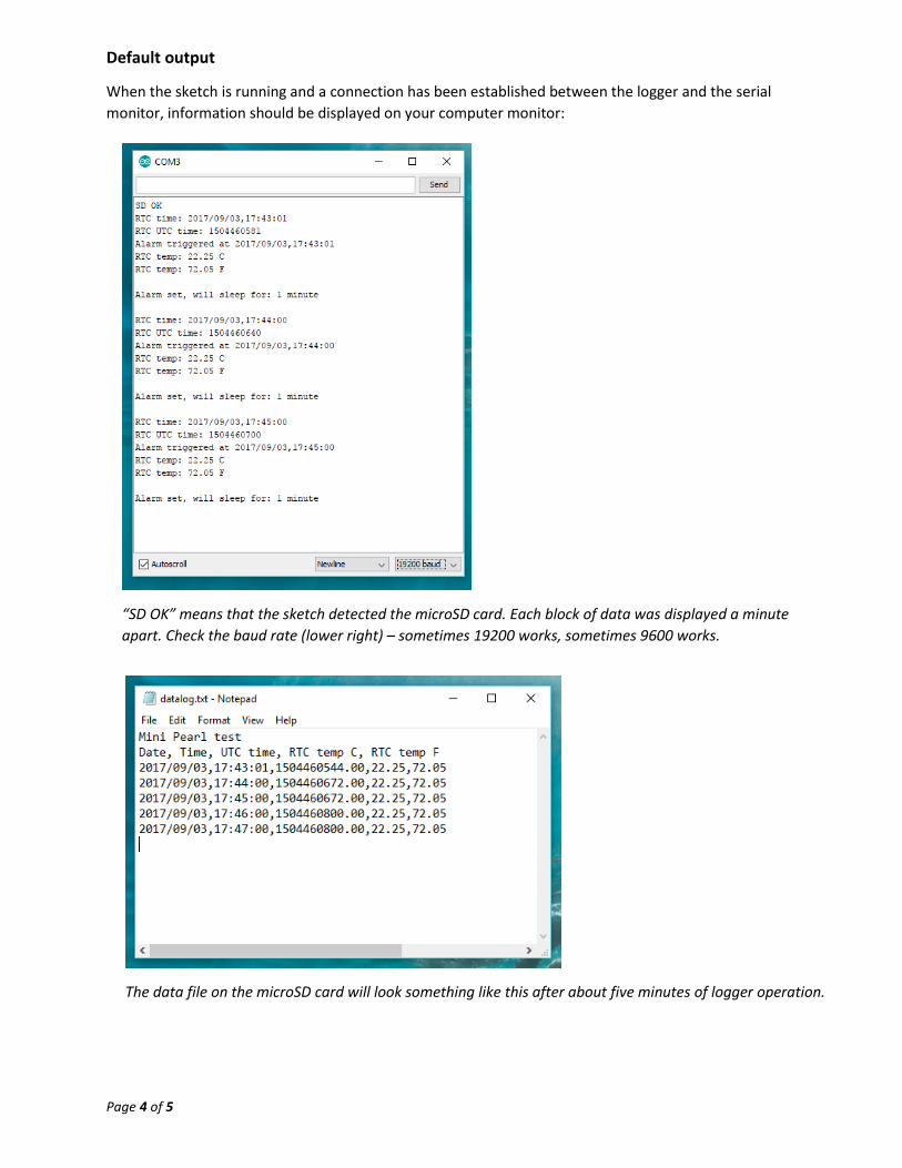
Default output
When the sketch is running and a connection has been established between the logger and the serial
monitor, information should be displayed on your computer monitor:
“SD OK” means that the sketch detected the microSD card. Each block of data was displayed a minute
apart. Check the baud rate (lower right) – sometimes 19200 works, sometimes 9600 works.
The data file on the microSD card will look something like this after about five minutes of logger operation.

Page 5 of 5
RGB LED
The RGB LED is optional. The default sketch includes code to change the color of the LED when the
logger is sleeping (red), when it wakes up (green), and when it is writing to the SD card (blue). If the LED
is not connected, the sketch will run normally. The LED is handy for troubleshooting and to confirm that
everything is operating normally when deploying the logger in the field when a serial monitor cannot be
used. It is especially handy when the LEDs on the Pro Mini and real-time clock have been disabled (to
save power).
Modifying the boards
To lower the power used by the logger and increase the time the logger can run on batteries, the LEDs
on the Pro Mini and real-time clock boards can be disabled by removing specific resistors. Removing
other resistors on the real-time clock and microSD board can further reduce power consumption. It is
quite easy to flick these tiny resistors off the boards with a soldering iron.
Remove these two resistors from the Pro Mini board.
Remove these two resistors from the real-time clock
board. (These photos are from Ed Mallon.)
Remove these three resistors from the
microSD card board (already removed
in this photo).