nov. 2007self-checking modulesslide 1 fault-tolerant computing hardware design methods
TRANSCRIPT
Nov. 2007 Self-Checking Modules Slide 1
Fault-Tolerant Computing
Hardware Design Methods
Nov. 2007 Self-Checking Modules Slide 2
About This Presentation
Edition Released Revised Revised
First Oct. 2006 Nov. 2007
This presentation has been prepared for the graduate course ECE 257A (Fault-Tolerant Computing) by Behrooz Parhami, Professor of Electrical and Computer Engineering at University of California, Santa Barbara. The material contained herein can be used freely in classroom teaching or any other educational setting. Unauthorized uses are prohibited. © Behrooz Parhami
Nov. 2007 Self-Checking Modules Slide 3
Self-Checking Modules
Nov. 2007 Self-Checking Modules Slide 4
Earl checks his balance at the bank.
Nov. 2007 Self-Checking Modules Slide 5
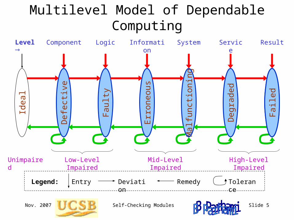
Multilevel Model of Dependable Computing
Component Logic Service ResultInformation SystemLevel
Low-Level Impaired Mid-Level Impaired High-Level ImpairedUnimpaired
EntryLegend: Deviation Remedy Tolerance
Ide
al
De
fect
ive
Fa
ulty
Err
one
ou
s
Ma
lfun
ctio
nin
g
De
gra
de
d
Fa
iled
Nov. 2007 Self-Checking Modules Slide 6
Main Ideas of Self-Checking Design
Functionunit
Status
Encoded input
Encoded output
Self-checking code checker
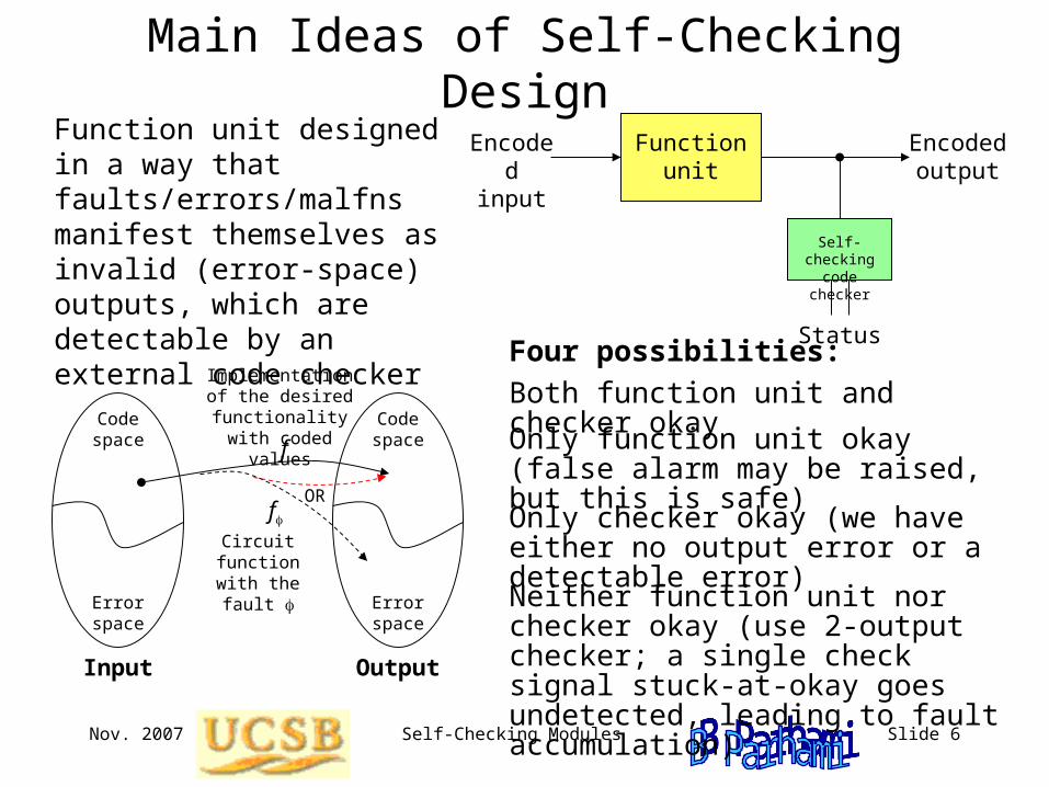
Function unit designed in a way that faults/errors/malfns manifest themselves as invalid (error-space) outputs, which are detectable by an external code checker
Input
Code space
Error space
Code space
Error space
Output
f
Implementation of the desired functionality with coded values
fCircuit function with the fault
OR
Four possibilities:
Both function unit and checker okay
Only function unit okay (false alarm may be raised, but this is safe)
Only checker okay (we have either no output error or a detectable error)
Neither function unit nor checker okay (use 2-output checker; a single check signal stuck-at-okay goes undetected, leading to fault accumulation)
Nov. 2007 Self-Checking Modules Slide 7
Cascading of Self-Checking Modules
Functionunit 1
Encoded input
Self-checking checker
Functionunit 2
Encoded output
Self-checking checker
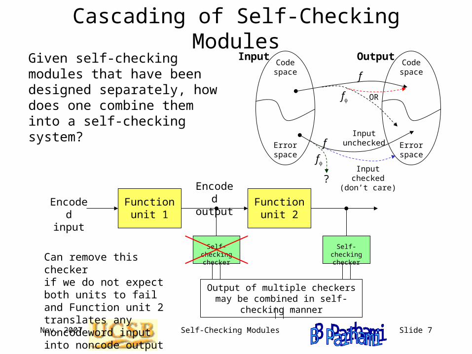
Given self-checking modules that have been designed separately, how does one combine them into a self-checking system?
Can remove this checker if we do not expect both units to fail and Function unit 2 translates any noncodeword input into noncode output
Output of multiple checkers may be combined in self-checking manner
Code space
Error space
Code space
Error space
Output
f
f OR
Input
Input uncheckedf
Input checked (don’t care)
f
?
Nov. 2007 Self-Checking Modules Slide 8
Totally-Self-Checking Error Signal Combining
Functionunit 1
Encoded input
Self-checking checker
Functionunit 2
Encoded output
Self-checking checker
In Out
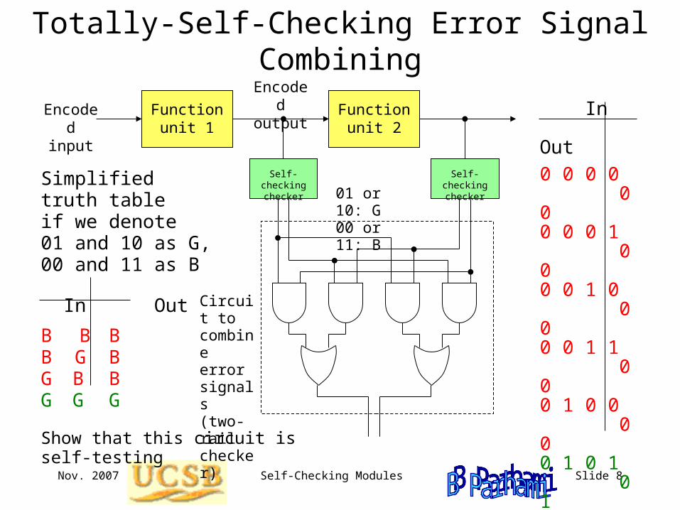
0 0 0 0 0 00 0 0 1 0 00 0 1 0 0 00 0 1 1 0 00 1 0 0 0 00 1 0 1 0 10 1 1 0 1 00 1 1 1 1 11 0 0 0 0 01 0 0 1 1 01 0 1 0 0 11 0 1 1 1 1 1 1 0 0 0 01 1 0 1 1 11 1 1 0 1 11 1 1 1 1 1
Simplified truth table if we denote 01 and 10 as G,00 and 11 as B
In Out
B B BB G BG B BG G G
Circuit to combine error signals(two-rail checker)
01 or 10: G00 or 11: B
Show that this circuit is self-testing
Nov. 2007 Self-Checking Modules Slide 9
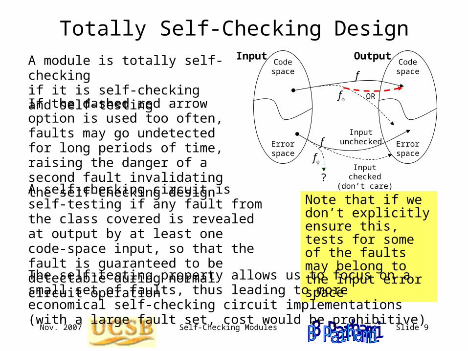
Totally Self-Checking Design
A module is totally self-checking if it is self-checking and self-testing
If the dashed red arrow option is used too often, faults may go undetected for long periods of time, raising the danger of a second fault invalidating the self-checking design
A self-checking circuit is self-testing if any fault from the class covered is revealed at output by at least one code-space input, so that the fault is guaranteed to be detectable during normal circuit operation
Code space
Error space
Code space
Error space
Output
f
f OR
Input
Input uncheckedf
Input checked (don’t care)
Note that if we don’t explicitly ensure this, tests for some of the faults may belong to the input error space
The self-testing property allows us to focus on a small set of faults, thus leading to more economical self-checking circuit implementations (with a large fault set, cost would be prohibitive)
f
?
Nov. 2007 Self-Checking Modules Slide 10
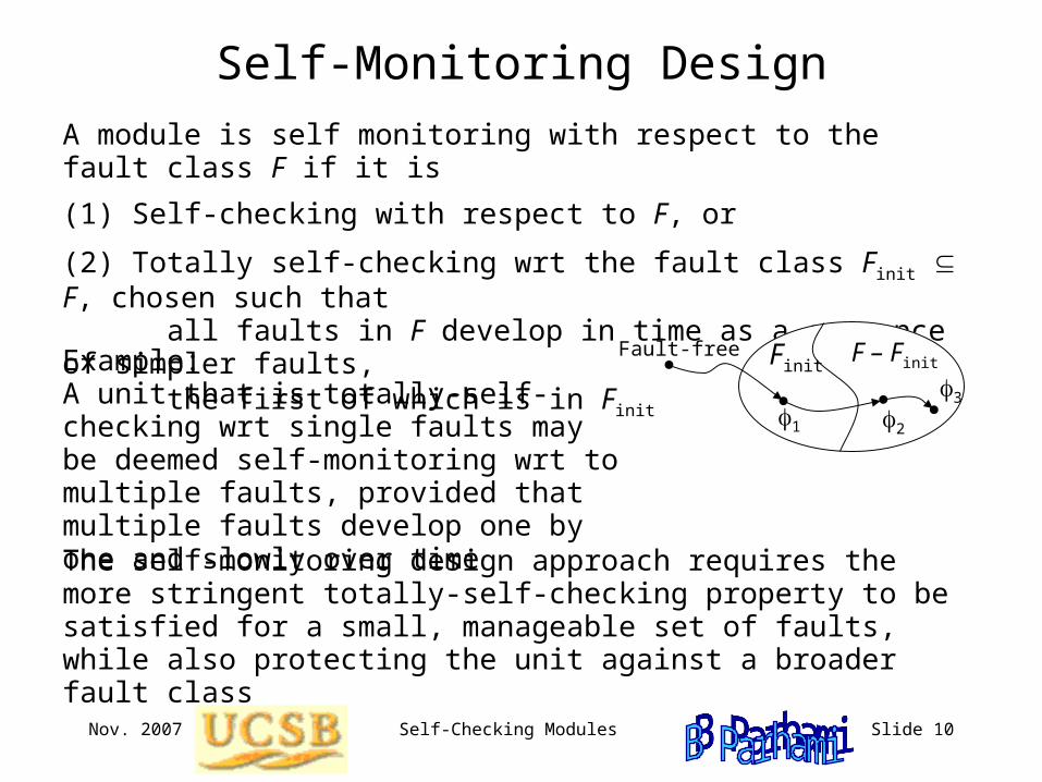
Self-Monitoring Design
A module is self monitoring with respect to the fault class F if it is
(1) Self-checking with respect to F, or
(2) Totally self-checking wrt the fault class Finit F, chosen such that all faults in F develop in time as a sequence of simpler faults, the first of which is in Finit
Example: A unit that is totally-self-checking wrt single faults may be deemed self-monitoring wrt to multiple faults, provided that multiple faults develop one by one and slowly over time
The self-monitoring design approach requires the more stringent totally-self-checking property to be satisfied for a small, manageable set of faults, while also protecting the unit against a broader fault class
Finit F – Finit
1 2
3
Fault-free
Nov. 2007 Self-Checking Modules Slide 11
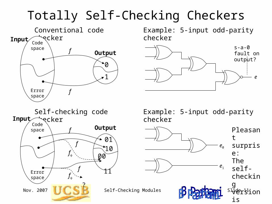
Totally Self-Checking CheckersConventional code checker
InputCode space
Error space
Output f
0
1
f
Pleasant surprise:The self-checking version is simpler!
InputSelf-checking code checker
Code space
Error space
Output f
01
00
f
10
11
f
f
f ?
Example: 5-input odd-parity checker
s-a-0 fault on output?
e
Example: 5-input odd-parity checker
e0
e1
Nov. 2007 Self-Checking Modules Slide 12
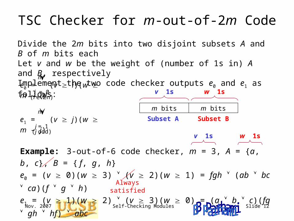
TSC Checker for m-out-of-2m Code
Divide the 2m bits into two disjoint subsets A and B of m bits eachLet v and w be the weight of (number of 1s in) A and B, respectively Implement the two code checker outputs e0 and e1 as follows:
e0 = (v i)(w m – i)i = 0
(i even)
m
e1 = (v j)(w m – j)j = 1
(j odd)
m
Always satisfied
Example: 3-out-of-6 code checker, m = 3, A = {a, b, c}, B = { f, g, h}
e0 = (v 0)(w 3) (v 2)(w 1) = fgh (ab bc ca)(f g h)
e1 = (v 1)(w 2) (v 3)(w 0) = (a b c)(fg gh hf) abc
v 1s w 1s
m bits m bits
v 1s w 1s
Subset A Subset B
Nov. 2007 Self-Checking Modules Slide 13
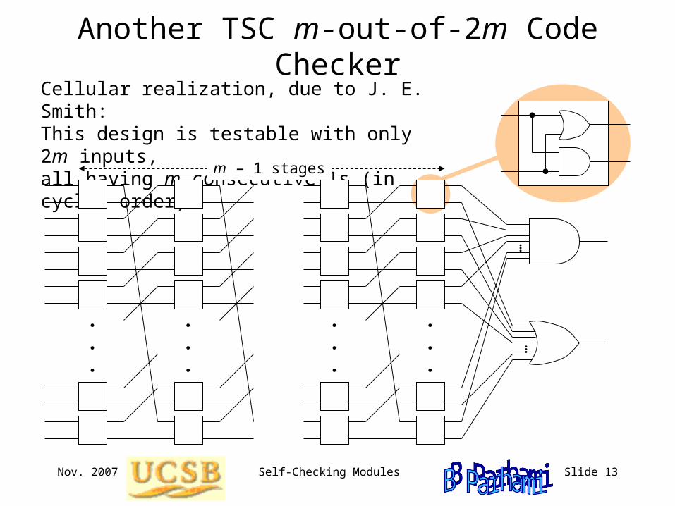
Another TSC m-out-of-2m Code CheckerCellular realization, due to J. E. Smith:This design is testable with only 2m inputs, all having m consecutive 1s (in cyclic order)
.
.
.
.
.
.
.
.
.
.
.
.
m – 1 stages
...
...
Nov. 2007 Self-Checking Modules Slide 14
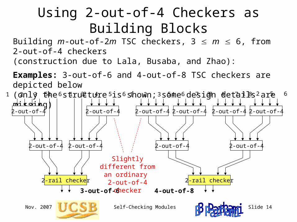
Using 2-out-of-4 Checkers as Building Blocks
Building m-out-of-2m TSC checkers, 3 m 6, from 2-out-of-4 checkers(construction due to Lala, Busaba, and Zhao):
Examples: 3-out-of-6 and 4-out-of-8 TSC checkers are depicted below(only the structure is shown; some design details are missing)
2-out-of-4
2-out-of-4
2-out-of-4
2-out-of-4
2-rail checker
1 2 3 4 3 4 5 65 6 1 2
3-out-of-6
2-out-of-4
2-out-of-4
2-out-of-4
2-out-of-4
2-out-of-4 2-out-of-4
2-rail checker
1 2 3 4 3 4 7 85 6 7 8 1 2 5 6
4-out-of-8
Slightly different from an ordinary 2-out-of-4 checker
Nov. 2007 Self-Checking Modules Slide 15
TSC Checker for k-out-of-n Code
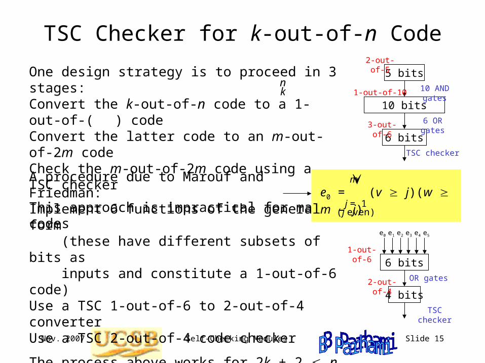
One design strategy is to proceed in 3 stages:Convert the k-out-of-n code to a 1-out-of-( ) codeConvert the latter code to an m-out-of-2m codeCheck the m-out-of-2m code using a TSC checker
This approach is impractical for many codes
nk
5 bits
10 bits
6 bits
2-out-of-5
1-out-of-10
3-out-of-6
10 AND gates
6 OR gates
TSC checker
A procedure due to Marouf and Friedman:Implement 6 functions of the general form (these have different subsets of bits as inputs and constitute a 1-out-of-6 code)Use a TSC 1-out-of-6 to 2-out-of-4 converterUse a TSC 2-out-of-4 code checker
The process above works for 2k + 2 n 4kIt can be somewhat simplified for n = 2k + 1
e0 = (v j)(w m – j)j = 1
(j even)
m
6 bits
4 bits
e0 e1 e2 e3 e4 e5
1-out-of-6
2-out-of-4 OR gates
TSC checker
Nov. 2007 Self-Checking Modules Slide 16
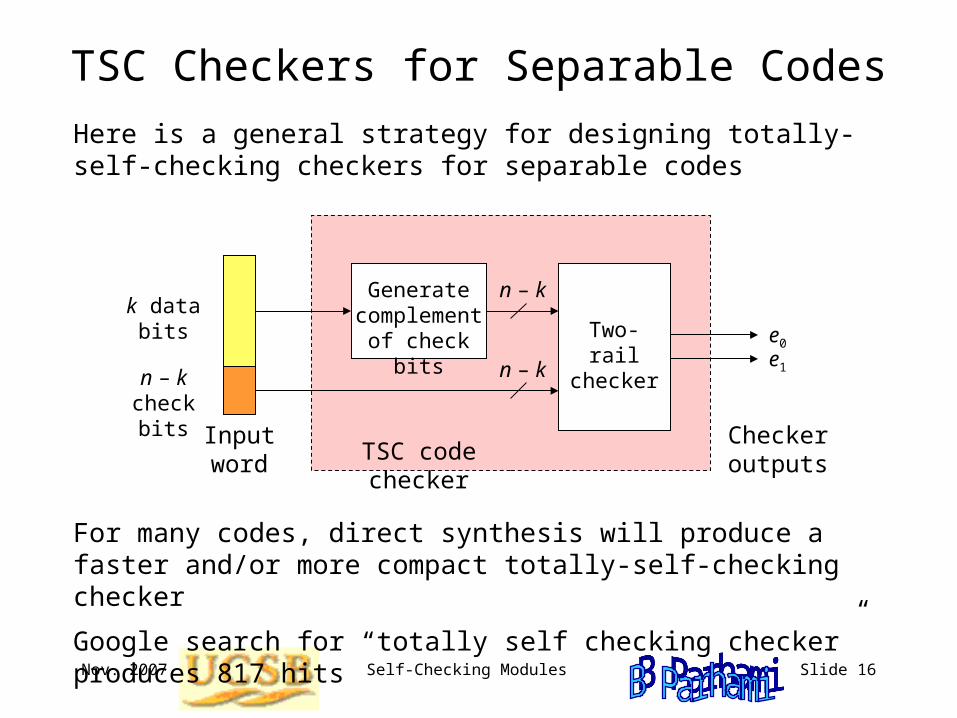
TSC Checkers for Separable Codes
Here is a general strategy for designing totally-self-checking checkers for separable codes
k data bits
n – k check bits
Input word TSC code checker
Generate complement of check bits
n – k
n – k
e0
e1
Two-rail checker
Checker outputs
For many codes, direct synthesis will produce a faster and/or more compact totally-self-checking checker
Google search for “totally self checking checker” produces 817 hits
Nov. 2007 Self-Checking Modules Slide 17
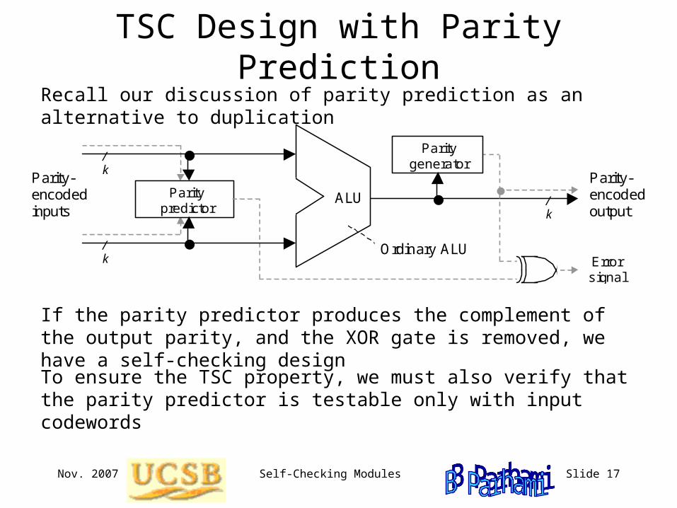
TSC Design with Parity PredictionRecall our discussion of parity prediction as an alternative to duplication
/ k
/ k
/ k
Parity- encoded inputs
ALU
Error signal
Parity- encoded output
Parity generator
Ordinary ALU
Parity predictor
If the parity predictor produces the complement of the output parity, and the XOR gate is removed, we have a self-checking design
To ensure the TSC property, we must also verify that the parity predictor is testable only with input codewords
Nov. 2007 Self-Checking Modules Slide 18
TSC Design with Residue Encoding
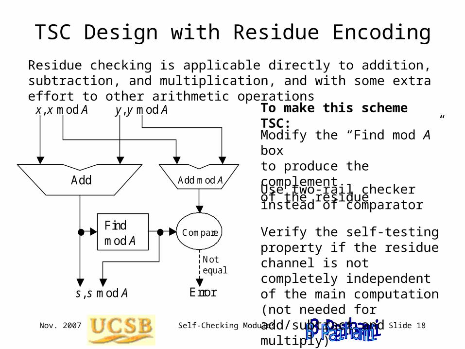
Residue checking is applicable directly to addition, subtraction, and multiplication, and with some extra effort to other arithmetic operations
Modify the “Find mod A” box to produce the complement of the residue
Use two-rail checker instead of comparator
Add
x, x mod A
Add mod A
Compare Find mod A
y, y mod A
s, s mod A Error
Not equal
Verify the self-testing property if the residue channel is not completely independent of the main computation (not needed for add/subtract and multiply)
To make this scheme TSC:
Nov. 2007 Self-Checking Modules Slide 19
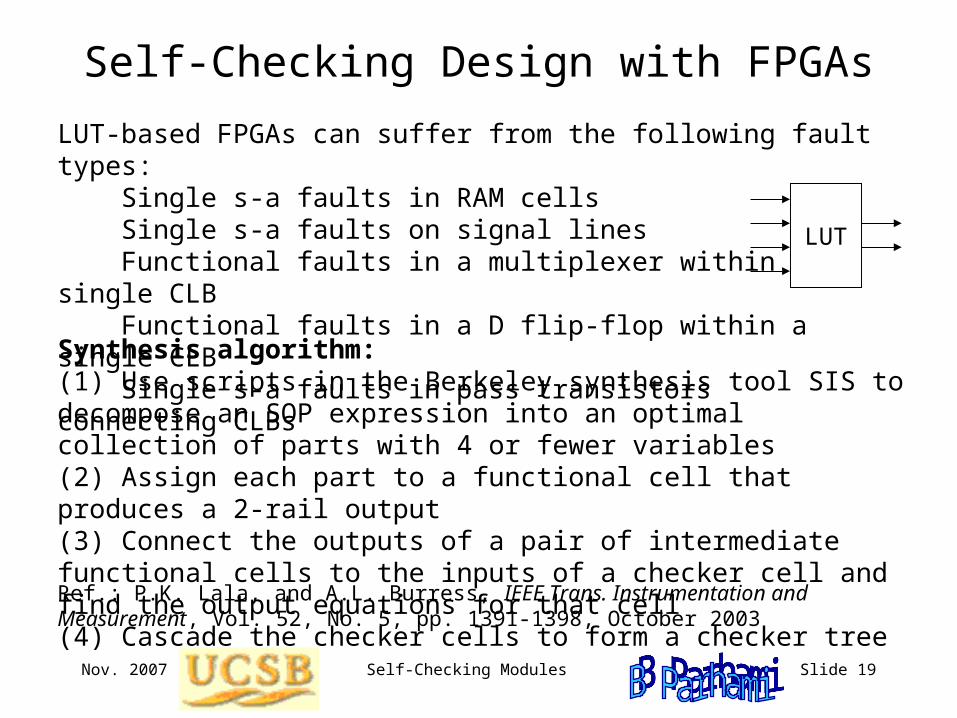
Self-Checking Design with FPGAs
Synthesis algorithm: (1) Use scripts in the Berkeley synthesis tool SIS to decompose an SOP expression into an optimal collection of parts with 4 or fewer variables(2) Assign each part to a functional cell that produces a 2-rail output(3) Connect the outputs of a pair of intermediate functional cells to the inputs of a checker cell and find the output equations for that cell(4) Cascade the checker cells to form a checker tree
LUT-based FPGAs can suffer from the following fault types: Single s-a faults in RAM cells Single s-a faults on signal lines Functional faults in a multiplexer within a single CLB Functional faults in a D flip-flop within a single CLB Single s-a faults in pass transistors connecting CLBs
Ref.: P.K. Lala, and A.L. Burress, IEEE Trans. Instrumentation and Measurement, Vol. 52, No. 5, pp. 1391-1398, October 2003
LUT
Nov. 2007 Self-Checking Modules Slide 20
Synthesis of TSC Systems from TSC Modules
Theorem 1: A sufficient condition for a system to be TSC with respect to all single-module failures is to add checkers to the system such that if a path leads from a module Mi to itself (a loop), then it encounters at least one checker
Theorem 2: A sufficient condition for a system to be TSC with respect to all multiple module failures in the module set A = {Mi} is to have no loop containing two modules in A in its path and at least one checker in any path leading from one module in A to any other module in A
System consists of a set of modules, with interconnections modeled by a directed graph
Optimal placement of checkers to satisfy these condition
Easily solved, when checker cost is the same at every interface
Nov. 2007 Self-Checking Modules Slide 21
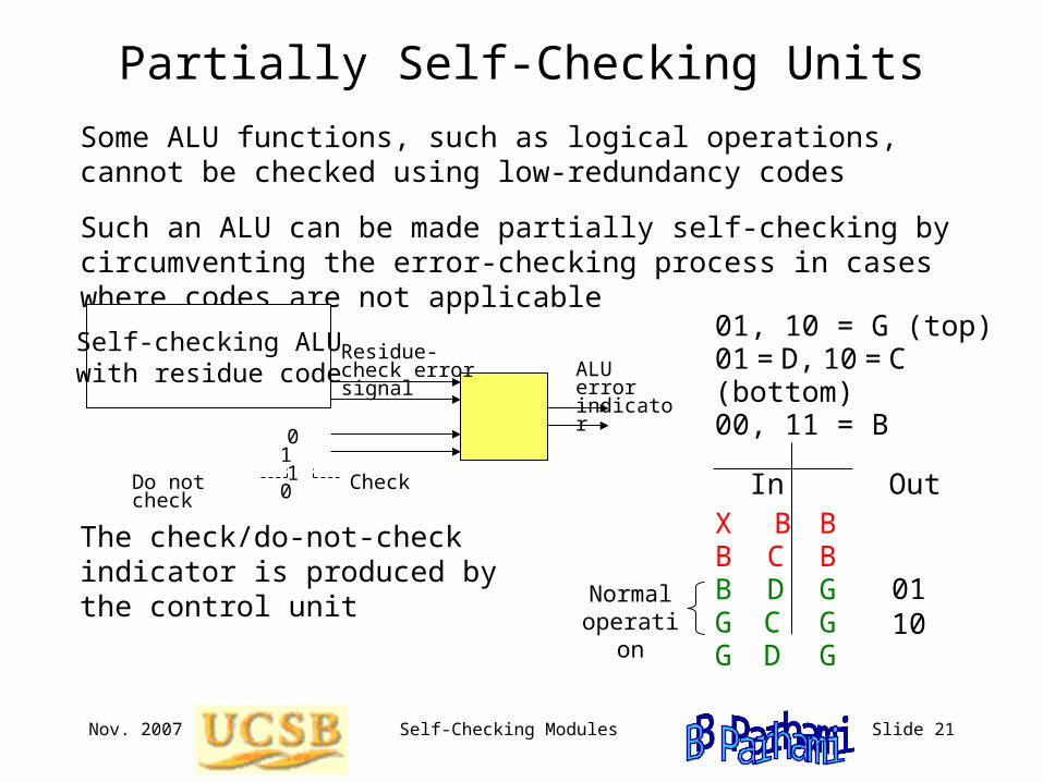
Partially Self-Checking Units
The check/do-not-check indicator is produced by the control unit
Some ALU functions, such as logical operations, cannot be checked using low-redundancy codes
Such an ALU can be made partially self-checking by circumventing the error-checking process in cases where codes are not applicable
Self-checking ALUwith residue code
0 1 1 0
Do not check
Check
Residue-check error signal ALU error
indicator
01, 10 = G (top)01 = D, 10 = C (bottom)00, 11 = B
In OutX B BB C BB D GG C G G D G
Normal operation
0110
Nov. 2007 Self-Checking Modules Slide 22
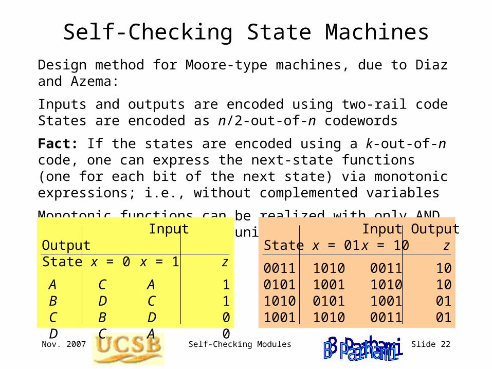
Self-Checking State MachinesDesign method for Moore-type machines, due to Diaz and Azema:
Inputs and outputs are encoded using two-rail codeStates are encoded as n/2-out-of-n codewords
Fact: If the states are encoded using a k-out-of-n code, one can express the next-state functions (one for each bit of the next state) via monotonic expressions; i.e., without complemented variables
Monotonic functions can be realized with only AND and OR gates, hence the unidirectional error detection capability
Input OutputState x = 0 x = 1 z
A C A 1 B D C 1 C B D 0 D C A 0
Input OutputState x = 01 x = 10 z
0011 1010 0011 100101 1001 1010 101010 0101 1001 011001 1010 0011 01