novaelectronics mc8082pe - takumi-sh.com · novaelectronics mc8082pe ......
TRANSCRIPT
MC8082PeNOVA electronics
MC8082Pe is a PCI-bus compliant PC/AT compatible circuit board equippedwith 2pcs of 4-axis motion control IC "MCX304".It can independently control 8-axis of either stepper motor or pulse type servomotor for position and speed controls.
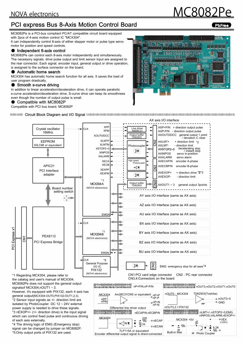
MC8082Pe can control each 8-axis motor independently and simultaneously.The necessory signals, drive pulse output and limit sensor input are assigned tothe rear connector. Each signal, encoder input, general output or drive operation,is assigned to the surface connector on the board.
MCX304 has automatic home search function for all axis. It saves the load ofuser program drastically.
In addition to linear acceleration/deceleration drive, it can operate parabolics-curve acceleration/deceleration drive. S-curve drive can keep its smoothnesseven though the number of output pulse is small.●Compatible with PCI bus board, MC8082P
MCX304-A
Line driverAM26C31
Output bufferTD62503
Photocoupler
High speed
XPPXPM
XLMTPXLMTM
XSTOP2~0XINPOS
XALARM
XECAXECB
Crystal oscillator16MHz
CLK
XEXPPXEXPM
EMGN
EEPROM93LC66 or equivalent
APIC21
PIX132
CLK
XOUT0/DCC
EMGN
CLK
0
84C
PEX8112
(NOVA electronics)
PCI Interfaceadapter
*4
*2
*1
*1
*2*3*2
PCI Express Bridge
Board numbersetting switch
MCX304-B(NOVA electronics)
General PurposeI/O IC
(NOVA electronics)
*5
Photocoupler
Output bufferTD62503
AXP+P/N + direction output pulseAXP-P/N - direction output pulseAXOUT0/DCC general output 1 point
AXLMT+ + direction limitAXLMT- - direction limit
AXINPOS servo in-positionAXALARM servo alarmAXECAP/N encoder A-phase
AXECBP/N encoder B-phase
AXEXOP+ + direction driveAXEXOP- - direction limit
/ deviation C clear
decelerating stop/ instant stop
AXOUT1 ~ 3 general output 3points
AX axis I/O interface
AY axis I/O Interface (same as AX axis)
AZ axis I/O Interface (same as AX axis)
AU axis I/O Interface (same as AX axis)
BX axis I/O Interface (same as AX axis)
BY axis I/O Interface (same as AX axis)
BZ axis I/O Interface (same as AX axis)
BU axis I/O Interface (same as AX axis)
EMG emergency stop for all axes
Encoder Input Signal Circuit
nOUT3,nOUT2,nOUT1,nOUT0
nECAP/N,nECBP/N nLMT+/-,nSTOP2~0,EMG,
nP+P/N,nP-P/N
Differential line driver output
Am26C31CNS or equivalentMCX304nPPnPM
nP+PnP-PnP+NnP-N
220
1K
TLP115A or equivalent
MCX304nECAP
nECAN
Encoder differential output signal is direct-connected.
nOUT0:MCX304
nOUT3~0GND
TD62503(Toshiba)
MCX304 +5V VEX(+24V)
Photo Coupler
nINPOS,nALARM,nEXOP+/-
General Output Circuit
nOUT3,2,1:PIX132
8.2KBuilt-in filter
Pulse Output Signal Circuit
Sensor input signal circuit
*1 Regarding MCX304, please refer tothe catalog and user's manual of MCX304.MC8082Pe does not support the general outputsignalsof MCX304,nOUT1 ~ 3.However, it's equipped with PIX132, each 4 axis hasgeneral output(MCX304-OUT0,PIX132-OUT1,2,3).*2 Sensor input signals as +/- direction limit areisolated by PhotoCoupler. DC 12 ~ 24V externalpower supply is needed to drive these signals.*3 nEXOP+/- (+/- direction drive) is the input signalwhich can control fixed pulse and continuous drivingof each axis externally.*4 The driving logic of EMG (Emergency stop)signal can be changed by jumper on MC8082P.*5:Only output ports of PIX132 are used.
CN1:PCI card edge connector CN2 : PC rear connectorCN3,4:Connectors on the board
8 axes (Independent, Simultaneous Control)PCI Express ×116 bit64 byte (Depend on Plug and Play function.)IRQ (Depend on Plug and Play function.)
●Pulse output circuit Differential line-drive (AM26C31) output●Pulse output speed 1PPS ~ 4MPPS●Pulse output speed accuracy ±0.1% (Depend on the setting speed)●S-curve Jerk 954 ~ 31.25×10⁹PPS/SEC2
●Accelrating/Deccelrating speed 125 ~ 500×106PPS/SEC●Drive speed 1 ~ 4×10⁶PPS●Output-pulse number 0 ~ 268,435,455 (Fixed pulse drive)
or Unlimited (Continuous drive)●Speed curve
Constant speed, symmetrical/non-symmetrical linear acceleration,symmetrical/non-symmetrical parabolic s-curve acceleration/deceleration drive.
●Fixed Pulse Drive decceleration modeAuto (non-symmetrical linear acceleration/deceleration is also allowed)/Manual
●Output-pulse numbers and drive speeds are changeable during the driving.●Independent 2-pulse system or 1-pulse 1-direction system is selectable.●Logical levels of drive pulse is selectable.
●Input Circuit High-speed photo coupler input.Connectable with differential line-driver.
●2-phase pulse style or Up / Down pulse style is selectable.●Pulse of each single,double or quad count edge evaluation is selectable.
(2-phase pulse style).
● Logic Position Counter (for output pulse) range Bit length: 32 bit● Real Position Counter (for feedback pulse) range Bit length: 32 bitTo read/write data is always possible.
● COMP+Register comparison range -1,073,741,824 ~ +1,073,741,823● COMP-Register comparison range -1,073,741,824 ~ +1,073,741,823● Status and signal outputs for the comparisons of position counters● To work as Software limit
● Automatic execution of Step 1 (high-speed near home search) →Step 2 (low-speed home search) →Step 3 (low-speed encoder Z-phase search) →Step 4 (high-speed offset drive).
Enable/Disable of each step and search direction is selectable.● Deviation counter clear output :Clear pulse width within the range of 10μ~20msec and logical level is selectable.
● The factors of occurring interrupt:..start/finish of a constant-speed drive during the acceleration/deceleration driving..end of the driving..transition to “position counter ≥ COMP-”..transition to “position counter < COMP-”..transition to “position counter ≥ COMP+”..transition to “position counter < COMP+”Enable/disable for these factors are selectable.
●EXOP+ and EXOP- signals for fixed/continuous drive●Input Circuit Photo coupler and IC built-in integral filter
●STOP0~2 3 points for each axis (STOP0:near home,STOP1:home, STOP2:encoder Z-phase input)
●Input Circuit Photo coupler and IC built-in integral filterEnable/disable and logical levels for each signal is selectable.
●ALARM (Alarm), INPOS (In Position Check)●Input Circuit Photo coupler and IC built-in integral filterEnable/disable and logical levels for each signal is selectable.
●DCC (Pin shared between deviation counter clear output and OUT0)●Output Circuit TD62503 output (open collector output)
●OUT0~3 4 points for each axis (Total: 4×8=32 points)●Output Circuit TD62503 output (open collector output)
●1 point for each + and - direction●Input Circuit Photo coupler and IC built-in integral filterLogical levels and decelerating/instant stop is selectable.
●EMG 1 point for all axes. Stop the drive pulse immediately for all axes.●Input Circuit Photo coupler and IC built-in integral filterLogical level is selectable by jumper on the board.
●Device driver for MC8000P●VC++,VB and C# Sample program●Evaluation tool program
Software and user's manual are not attached to MC8082Pe.Please contact us or our distributor directly when you need.You can also download it on our website.
●Temperature Range for Driving 0 ~ + 45°C (No condensation)●Power Voltage for Driving +3.3V ± 5 %
(Consumption current 1300mA max.)●External Supply Voltage +24V●Board Dimensions 174.6×106.7mm
(Connectors and brackets are excluded)●I/O Connector Type CN2:FX2B-100PA-1.27DS (Hirose)
CN3:HIF3FC-50PA-2.54DS (Hirose)CN4:HIF3FC-30PA-2.54DS (Hirose)
●Accessories CN2:FX2B-100SA-1.27R (Hirose) with 1.2m cableCN3:HIF3BB-50D-2.54R (Hirose) connector onlyCN4:HIF3BA-30D-2.54R (Hirose) connector only
Distributor
MC8082PeNOVA electronics
WindowsXP, WindowsVista and Windows7 are registered trademark of Microsoft Corporation.The specifications are subject to change without notice due to the technical development. 2013.2
3F,Grand Axe Bldg.,1-7-20 Uehara,Shibuya-Ku,Tokyo 151-0064,JapanWEB SITE http://www.novaelec.co.jp/eng/index_e.htmlEMAIL ADDRESS [email protected] 81-3-5738-3666 FAX 81-3-5738-3665
electronics达格美(上海)集成电路有限公司
地址 : 上海市浦东新区张杨路188号汤臣中心B栋801室电话 : 021-5840-8299 E-mail : [email protected]传真 : 021-5840-1590 WEB : www.takumi-sh.com
TAKUMI (SHANGHAI) INTEGRATED CUICUIT CO.,LTD.