novel aspects of second-harmonic generation …...kalle koskinen novel aspects of second-harmonic...
TRANSCRIPT

Tampere University of Technology
Novel Aspects of Second-harmonic Generation from Thin Films and Surfaces
CitationKoskinen, K. (2018). Novel Aspects of Second-harmonic Generation from Thin Films and Surfaces. (TampereUniversity of Technology. Publication; Vol. 1579). Tampere University of Technology.
Year2018
VersionPublisher's PDF (version of record)
Link to publicationTUTCRIS Portal (http://www.tut.fi/tutcris)
Take down policyIf you believe that this document breaches copyright, please contact [email protected], and we will remove accessto the work immediately and investigate your claim.
Download date:18.05.2020

Kalle KoskinenNovel Aspects of Second-harmonic Generation from ThinFilms and Surfaces
Julkaisu 1579 • Publication 1579
Tampere 2018
Tampereen teknillinen yliopisto. Julkaisu 1579 Tampere University of Technology. Publication 1579 Kalle Koskinen Novel Aspects of Second-harmonic Generation from Thin Films and Surfaces Thesis for the degree of Doctor of Science in Technology to be presented with due permission for public examination and criticism in Tietotalo Building, Auditorium TB109, at Tampere University of Technology, on the 12th of October 2018, at 12 noon. Tampereen teknillinen yliopisto - Tampere University of Technology Tampere 2018

Doctoral candidate: Kalle Koskinen
Laboratory of Photonics Faculty of Natural Sciences Tampere University of Technology Finland
Supervisor: Professor Martti Kauranen Laboratory of Photonics Faculty of Natural Sciences Tampere University of Technology Finland
Pre-examiners: Professor Isabelle Staude Institute of Applied Physics Abbe Center of Photonics Friedrich Schiller University Jena Germany Doctor Jerry Dadap Department of Electrical Engineering Columbia University The United States of America
Opponent: Professor Thierry Verbiest Molecular Imaging and Photonics Faculty of Bioengineering Sciences Katholieke Universiteit Leuven Belgium
ISBN 978-952-15-4209-1 (printed) ISBN 978-952-15-4233-6 (PDF) ISSN 1459-2045

iii
ABSTRACT
Second-harmonic generation is a second-order nonlinear optical process that can
be utilized in a variety of applications. The main limitation of second-harmonic
generation is that it is forbidden for centrosymmetric materials. Enabled by the
advances in nanofabrication, considerable amount of attention has been given to
the miniaturization of optical components for integrated photonics. As a result, the
expansion of the range of second-order materials is more desirable than ever.
In this work, we developed a sophisticated analytical model to characterize the
second-harmonic response of thin �lms using various traditional experimental meth-
ods. A thin material system brings forth additional complexity due to the presence of
re�ections that have signi�cant consequences to the nonlinear characterization pro-
cess both qualitatively and quantitatively. Using the developed model, we studied
second-harmonic generation from various material candidates in order to determine
whether they have potential as novel nonlinear materials. These materials are com-
posites consisting of multiple alternating dielectric layers, silicon nitride, indium
selenide, and gold nanoparticle �lms coated with titanium dioxide.
The results of this work indicate, that 1) multilayered composites are in fact a
promising solution to circumvent the requirement for non-centrosymmetry of second-
harmonic generation, 2) indium selenide was found to possess a signi�cant second-
harmonic response and to show potential for nonlinear applications, 3) the already
strong second-harmonic generation from silicon nitride was enhanced six-fold by
material composition, and 4) the second-harmonic response from gold nanoisland
�lms was enhanced 40-fold by a novel non-resonant local-�eld enhancement process,
controlled by tuning the thickness of dielectric coating covering the nanoislands.
Lastly, the utility of the developed model was demonstrated by showing that using
a traditional simpler model that neglects re�ections results in both qualitatively
and quantitatively erroneous results in the recognition of multipolar contributions
to second-harmonic generation from thin �lms. In addition, the general nature of
the model was highlighted by the fact that the same model was used successfully to
analyse the various di�erent experimental con�gurations used in this work.

iv

v
TIIVISTELMÄ
Taajuudenkahdennus on toisen kertaluvun epälineaarinen optinen prosessi jota voi-
daan hyödyntää monissa sovelluksissa. Taajuudenkahdennuksen tärkein rajoite on
se, että prosessi on kielletty keskeissymmetrisissä materiaaleissa. Nanoteknologian
kehityksen mahdollistamana optisten laitteiden miniaturisointi integroidun fotonii-
kan tarpeisiin on saanut osakseen suuren määrän huomiota. Tästä syystä uusien
toisen kertaluvun epälineaaristen materiaalien löytäminen olisi erityisen hyödyllistä.
Tässä työssä kehitettiin hienostunut analyyttinen malli ohutkalvojen toisen ker-
taluvun epälineaarisen vasteen karakterisointiin käyttäen erinäisiä tyypillisiä mit-
taustekniikoita. Ohutkalvojen analysointi on erityisen haasteellista, koska niiden
äärimmäisen pieni paksuus johtaa monimutkaisiin heijastusilmiöihin joilla on edel-
leen merkittävä vaikutus karakterisointiprosessiin sekä kvalitatiivisesti että kvan-
titatiivisesti. Työssä tutkittiin taajuudenkahdennusta erinäisistä materiaaleista ja
niiden potentiaalia uusina epälineaarisina materiaaleina käyttäen kehitettyä mallia.
Tutkittavat materiaalit olivat useista ultraohuista kalvoista sykleinä koostuva kom-
posiittikalvo, piinitridi, indiumselenidi ja titaanidioksiidilla päällystetty kultanano-
partikkelikalvo.
Työn tulokset osoittavat, että: 1) komposiittikalvot ovat lupaava metamateriaaliryh-
mä taajuudenkahdennuksen keskeissymmetriarajoitteiden kiertämiseksi, 2) indium-
selenidin taajuudenkahdennusvaste on merkittävä ja näin ollen indiumselenidi on po-
tentiaalinen materiaali epälineaarisiin optisiin sovelluksiin, 3) piinitridin voimakasta
taajuudenkahdennusvastetta voidaan vahvistaa entisestään jopa kuusinkertaiseksi
säätämällä piinitridin kemiallista koostumusta ja 4) kultananohiukkaskalvon taa-
juudenkahdennusvaste voidaan kasvattaa jopa 40-kertaiseksi uudenlaisen epäreso-
nantin lähikenttäilmiön avuttaa. Lisäksi kehitettyä hienostunutta mallia verrattiin
yksinkertaisempaan heijastusilmiöt laiminlyövään perinteiseen malliin, ja yksinker-
taisen mallin havaittiin tuottavan sekä kvalitatiivisesti että kvantitatiivisesti virheel-
lisiä tuloksia ohutkalvojen multipoli-taajuudenkahdennuksen karakterisoinnissa. Ke-
hitettyä mallia käytettiin kaikkien työn tulosten analysointiin, mikä kuvastaa mallin
yleistä luonnetta.

vi

vii
PREFACE
The research related to this Thesis was carried out at the Laboratory of Photonics
under the Faculty of Natural Sciences in Tampere University of Technology. The
Thesis work was mainly funded by a personal fellowship from Vilho, Yrjö and Kalle
Väisälä Foundation administered by the Finnish Academy of Sciences, for which I
am extremely grateful.
I would like express my heartfelt gratitude towards my supervisor professor Martti
Kauranen, whose superb expertise, kindness and patience have been invaluable. In
addition, I thank all of my co-authors with whom the research to which this Thesis is
based on was conducted, as well as all of my colleagues in the amazing environment
of the Laboratory of Photonics. Finally, my beloved family and friends, without
whose support this work would have not been possible, deserve all the praise I can
possibly give.
This has truly been an enjoying and interesting ride; I did not really feel its length.
As this Thesis work is approaching its conclusion, so is, in a way, a chapter in my
life. Indeed, it is with excitement but also with a certain longing that I approach this
milestone. I believe, that this experience as a whole has taught me much, molded
me, even. I know, that I will cherish the memories of this journey, and never forget
them.
Tampere 25.9.2018
Kalle Koskinen

viii

ix
CONTENTS
Abstract . . . . . . . . . . . . . . . . . . . . . . . . . . . . . . . . . . . . . . . iii
Tiivistelmä . . . . . . . . . . . . . . . . . . . . . . . . . . . . . . . . . . . . . v
Preface . . . . . . . . . . . . . . . . . . . . . . . . . . . . . . . . . . . . . . . vii
List of Publications . . . . . . . . . . . . . . . . . . . . . . . . . . . . . . . . . xvii
Author's Contribution . . . . . . . . . . . . . . . . . . . . . . . . . . . . . . . xix
1. Introduction . . . . . . . . . . . . . . . . . . . . . . . . . . . . . . . . . . . 1
1.1 Research objectives and scope of the Thesis . . . . . . . . . . . . . . 2
1.2 Structure of the Thesis . . . . . . . . . . . . . . . . . . . . . . . . . . 4
2. Optics of layered structures . . . . . . . . . . . . . . . . . . . . . . . . . . 7
2.1 Maxwell's equations and the homogeneous wave equation . . . . . . . 7
2.2 Refraction and re�ection . . . . . . . . . . . . . . . . . . . . . . . . . 9
2.3 Green's function formalism . . . . . . . . . . . . . . . . . . . . . . . . 12
2.4 Total �elds in layerered structures . . . . . . . . . . . . . . . . . . . . 15
3. Nonlinear optics and source polarization . . . . . . . . . . . . . . . . . . . 19
3.1 SHG susceptibility . . . . . . . . . . . . . . . . . . . . . . . . . . . . 21
3.2 Electric-dipole SHG from layered structures . . . . . . . . . . . . . . 25
3.3 Multipolar SHG from layered structures . . . . . . . . . . . . . . . . 30
4. Experiments and samples . . . . . . . . . . . . . . . . . . . . . . . . . . . 35
4.1 Single-beam setup . . . . . . . . . . . . . . . . . . . . . . . . . . . . . 35
4.2 Two-beam setup . . . . . . . . . . . . . . . . . . . . . . . . . . . . . . 39
4.3 Multilayer composite materials . . . . . . . . . . . . . . . . . . . . . . 40
4.4 Silicon nitride . . . . . . . . . . . . . . . . . . . . . . . . . . . . . . . 42
4.5 Indium selenide . . . . . . . . . . . . . . . . . . . . . . . . . . . . . . 44
4.6 Nanoisland �lms . . . . . . . . . . . . . . . . . . . . . . . . . . . . . 45

x
5. Results . . . . . . . . . . . . . . . . . . . . . . . . . . . . . . . . . . . . . . 47
5.1 SHG from multilayer structures . . . . . . . . . . . . . . . . . . . . . 47
5.2 Multipolar SHG from thin �lms . . . . . . . . . . . . . . . . . . . . . 50
5.3 SHG from InSe thin �lms . . . . . . . . . . . . . . . . . . . . . . . . 53
5.4 Tuning SHG from SiN by material composition . . . . . . . . . . . . 55
5.5 Non-resonant enhancement of SHG from metal-dielectric composites . 59
6. Conclusions . . . . . . . . . . . . . . . . . . . . . . . . . . . . . . . . . . . 61
References . . . . . . . . . . . . . . . . . . . . . . . . . . . . . . . . . . . . . . 64
Publications . . . . . . . . . . . . . . . . . . . . . . . . . . . . . . . . . . . . . 79

xi
SYMBOLS AND ABBREVIATIONS
In this work scalar variables are written in italics and vectorial variables in bold.
Symbols
Axz E�ective o�-diagonal SHG component
B Magnetic �ux density
B± Magnetic �ux density of �eld propagating along ± direction
c Speed of light
Cp/s Fabry-Perot re�ection factor
D Thickness of the nonlinear medium
D Electric displacement
E Electric �eld
EL Local non-propagating response
E± Electric �eld propagating along ± direction
ET± Total electric �eld propagating along ± direction
Eout Total SHG �eld leaving the medium
f ζ,η,κ Polarization signature describing ζ polarized SHG from η and κ po-
larized fundamental �elds
G Dyadic Green's function
H(z) Heaviside step function
H Magnetic �eld
I Irradiance
i Imaginary unit
J Local �eld factor

xii
k Wave number
Kp/s± Factor connecting the p/s-polarized fundamental �eld incident to the
medium with the total ± propagating p/s �eld
kx Transverse component of the wave vector
k Wave vector
Kp/s± Factor describing the contribution of ± propagating SHG �eld to the
total downward propagating SHG �eld leaving the medium
k± Wave vector of �eld propagating along ± direction
k± Unit vector along the wave vector of �eld propagating in ± direction
Labc Projection of unit polarization vector a ∈ {pc, s} of c ∈ {±} propa-gating fundamental �eld to vector b ∈ {x, y, z}
Labc Projection of unit vector b ∈ {x, y, z} to polarization vector a ∈{p
c, s} of c ∈ {±} propagating SHG �eld
M Magnetization
n Refractive index
p± Unit vector along the p-polarization of �eld propagating in ± direc-
tion
P Material polarization
P0 Elementary source polarization
PNL Nonlinear part of material polarization
Q Electric quadrupolarization
q Quantity q evaluated for second-harmonic generation
qa/b Quantity q evaluated for fundamental �eld a/b
r Spatial coordinate
rpit The Fresnel �eld re�ection coe�cient for p polarization from medium
i to t

xiii
rsit The Fresnel �eld re�ection coe�cient for s polarization from medium
i to t
s Unit vector along the s polarization
t Time
tpit The Fresnel �eld transmission coe�cient for p polarization from
medium i to t
tsit The Fresnel �eld transmission coe�cient for s polarization from medium
i to t
U = [uξ,τ ] Matrix describing the connection between polarization signatures
and SHG susceptibility components
w Absolute value of the z-component of the wave vector
w± z-component of the wave vector for �eld propagating in ± direction
x, y, z Unit vectors of cartesian coordinates
z0 z-coordinate of the elementary polarization sheet
ω Angular frequency
χ(1)e Linear electric susceptibility
χ(2)ijk SHG susceptibility tensor component i, j, k
χ(2) SHG susceptibility tensor
δij Kronecker delta
δ(z) Dirac delta function
δ′ Separable multipolar parameter
ε0 Electric permittivity of vacuum
Φφ,β,γ Phase-mismatch factor for φ propagating SHG from β and γ propa-
gating fundamental �elds
Φ′φ,β,γ Phase-mismatch factor for φ propagating SHG from β and γ propa-
gating fundamental �elds a and b, respectively

xiv
µ0 Magnetic permeability of vacuum
θ Angle of propagation
[a↔ b] Term with �eld subscripts a, b interchanged
c.c. Complex conjugate term
∇ Di�erential operator

xv
Abbreviations
ALD Atomic layer deposition
BS Beam splitter
CMOS Complementary metal-oxide semiconductor
ED Electric-dipole
HWP Half-wave plate
InSe Indium selenide
LF Local �eld
LPCVD Low pressure chemical vapor deposition
LP Linear polarizer
MCM Multilayer composite material
MNS Metal nanostructures and metal-dielectric composites
MP Multipole
PECVD Plasma-enhanced chemical vapor deposition
PMT Photomultiplier tube
QWP Quarter-wave plate
RF Radio frequency
SHG Second-harmonic generation
SiN Silicon nitride

xvi

xvii
LIST OF PUBLICATIONS
Publication I Stéphane Clemmen, Artur Hermans, Eduardo Solano, Jolien Dendooven,
Kalle Koskinen, Martti Kauranen, Edouard Brainis, Christophe Detav-
ernier and Roel Baets, "Atomic layer deposited second-order nonlinear
optical metamaterial for back-end integration with CMOS-compatible
nanophotonic circuitry," Optics Letters 40, 5371-5374 (2015) [1]
Publication II Kalle Koskinen, Robert Czaplicki, Tommi Kaplas and Martti Kauranen,
"Recognition of multipolar second-order nonlinearities in thin-�lm sam-
ples," Optics Express 24, 4972-4978 (2016) [2]
Publication III Kalle Koskinen, Abdallah Slablab, Sasi Divya, Robert Czaplicki, Semen
Chervinskii, Madanan Kailasnath, Padmanabhan Radhakrishnan and
Martti Kauranen, "Bulk second-harmonic generation from thermally
evaporated indium selenide thin �lms," Optics Letters 42, 1076-1079
(2017) [3]
Publication IV Kalle Koskinen, Robert Czaplicki, Abdallah Slablab, Tingyin Ning, Ar-
tur Hermans, Bart Kuyken, Vinita Mittal, Ganapathy Senthil Murugan,
Tapio Niemi, Roel Baets and Martti Kauranen, "Enhancement of bulk
second-harmonic generation from silicon nitride �lms by material com-
position," Optics Letters 42, 5030-5033 (2017) [4]
Publication V Semyon Chervinskii, Kalle Koskinen, Sergey Scherbak, Martti Kaura-
nen and Andrey Lipovskii, "Nonresonant local �elds enhance second-
harmonic generation from metal nanoislands with dielectric cover," Phys-
ical Review Letters 120, 113902 (2018) [5]

xviii

xix
AUTHOR'S CONTRIBUTION
Publication I The author provided some consulting on the planning of the nonlinear
experiment and signi�cant consulting on the nonlinear analysis. The au-
thor conducted experiments and analysis on the calibration of the glass
substrate. S.C, A.H., E.S., and J.D conducted the rest of the experi-
ments and analysis and wrote most of the paper. The author contributed
to the writing process via comments, corrections and consultation. All
co-authors provided valuable insights on the writing process.
Publication II The author planned the experiments, conducted the nonlinear experi-
ments, conducted all of the analysis and wrote the manuscript. R.C.
provided help with the experiments, T.K. conducted the linear experi-
ments, and all co-authors provided valuable insights on the writing pro-
cess.
Publication III The author contributed considerably to the planning of the experiments,
conducted approximately half of the nonlinear experiments, conducted
all of the nonlinear analysis and wrote approximately 60% of the manu-
script. A.S. wrote the rest of the manuscript and provided valuable
assistance with experiments, S.D. fabricated the samples, R.C. provided
help with the experiments, S.C. conducted the linear experiments and
all co-authors provided valuable insights on the writing process.
Publication IV The author contributed considerably to the planning of the experiments,
conducted almost all of the nonlinear experiments, conducted all of the
nonlinear analysis and wrote approximately 90% of the manuscript. R.C.
provided particularly valuable insights and wrote a small portion of the
manuscript, and A.S. helped with the nonlinear experiments. T. Niemi,
A.H. and B.K. fabricated the samples, V.M and G.S.M. conducted the
loss measurements, and T. Ning provided help with the writing. All
co-authors provided valuable insights on the writing process.

xx
Publication V The author contributed considerably to the planning of the experi-
ments, conducted all of the nonlinear experiments and conducted all
of the nonlinear analysis. The author wrote a small portion of the
manuscript and contributed to the writing process via comments, cor-
rections and consultation. S.C. fabricated the samples, S.S. conducted
the modelling and all co-authors provided valuable insights on the writ-
ing process.
1
1. INTRODUCTION
The �eld of nonlinear optics is de�ned by the study of phenomena where the optical
response of a material depends on the interacting optical �elds in a nonlinear man-
ner, which occurs in the presence of intense light �elds [6]. Thus, it is unsurprising
that the invention of laser marks the de facto beginning of nonlinear optics [7], as
evidenced by the consequent emergence of multiple observations of nonlinear op-
tical e�ects such as second-harmonic generation [8�14]. The observation of other
nonlinear e�ects such as third-harmonic generation, sum-frequency generation and
di�erence-frequency generation soon followed [9, 15, 16]. However, second-order ef-
fects, such as second-harmonic generation, are the lowest-order coherent frequency
conversion processes and thus remain interesting due to the gradual weakening of
the nonlinear e�ects with increasing order of nonlinearity [6, 17].
Second-harmonic generation is an instantaneous process where two incident pho-
tons at a fundamental frequency are annihilated and one photon at the doubled
frequency is generated [6, 18]. Under the electric-dipole approximation of the light-
matter interaction, the process is governed by a polar third-rank tensor and is thus
forbidden for centrosymmetric materials [17,19]. For this reason, studies of second-
harmonic generation have been limited to systems of lower symmetry, such as sur-
faces [11, 12, 14], crystals [8, 9, 20�22] and for example chiral molecules [23�26]. It
should be noted that this limitation can become advantageous when the goal is to
probe surface or symmetry features of a material [27�29]. However, if high nonlinear-
ity is required, the non-centrosymmetry requirement remains an important problem.
Several methods have been utilized to arti�cially create materials with high second-
order nonlinearity, such as poling [30�33], Mie-resonant structures [34], resonant
dielectric structures [35], symmetry-breaking strain [36�38], stacking of ultrathin
layers [39,40], plasmon enhancement in metal nanostructures [41] and utilizing mul-
tipolar (magnetic-dipole and electric-quadrupole) contributions to the second-order
nonlinear response [42].

2 1. Introduction
Due to advancements in nanofabrication during recent decades, the miniaturiza-
tion of optical devices has become more realistic [43�45]. As a consequence, there
has been considerable attention towards integrated photonics, i.e., the integration
of multiple photonic devices together on a substrate [46�50]. Silicon on insulator
is often used as the basis of these devices, as it enables the use of the existing
complementary metal-oxide semiconductor infrastructure established for integrated
electronic circuits [43, 46�48]. As some of the desired functionalities for these pho-
tonic devices rely on second-order e�ects [51�56], expanding the range of suitable
nonlinear materials has become even more desirable.
In order to expand the range of nonlinear materials, an experimental methodology
for the nonlinear characterizaton of the candidate materials must be established.
The characterization is often most convenient to do by using thin-�lm samples. The
second-harmonic response of a material is then typically characterized by an exper-
iment where the polarizations of the fundamental beam and the second-harmonic
beam as well as the angle of incidence are controlled in order to access the various
susceptibility tensor components of the material [26, 57�59]. The most traditional
method, known as the Maker-fringe method, utilizes variable angle of incidence for
�xed choices of polarization for the fundamental and detected SHG beam [57, 58].
This method has been further extended to account for absorption and birefrin-
gence [60]. Another approach is to have the angle of incidence �xed while conduct-
ing multiple measurements with di�erent combinations of the polarization of the
fundamental and SHG beams [26].
Lastly, it was discovered early that if magnetic-dipole and electric-quadrupole con-
tributions are taken into account, second-harmonic generation is allowed even in
centrosymmetric media [17, 61, 62]. The separation of these contibutions from the
electric-dipole contribution of the material surface has been a long-standing prob-
lem in nonlinear optics [59, 63]. However, it was later found out that this could be
done by second-harmonic generation based on the use of two non-collinear excitation
beams at the fundamental frequency [64�67].
1.1 Research objectives and scope of the Thesis
As discussed above, expansion of the range of novel nonlinear materials is highly
desirable and second-order nonlinear materials are particularly hard to come by
due to the symmetry restrictions associated with second-order processes. Thus, the

1.1. Research objectives and scope of the Thesis 3
ultimate research objective of this work is to expand the range of materials with
high second-order response.
We limit our research methodology to the consideration of the second-harmonic
response, as its presence already indicates that the symmetry restrictions are over-
come. In addition, due to the physical similarities between second-harmonic gen-
eration and other second-order processes, it is likely that a material with a strong
second-harmonic response exhibits high second-order nonlinearity in general. This
limitation of scope is highly bene�cial for the practical experimental methodology
and the associated analysis.
Our ultimate research objective can be separated into 3 sub-objectives all contribut-
ing to the ultimate objective: 1) Finding a high second-harmonic response from a
material that was previously unknown to possess one, 2) Finding a method to en-
hance the second-harmonic response of a material that was previously known to
possess one, and 3) Improving the experimental methodology of nonlinear charac-
terization, contributing to the ultimate objective.
In order to determine the nonlinear response, we utilize the experiments presented
in Refs. [26, 57] and expand the analysis to the case of thin �lms using the theo-
retical framework presented in Ref. [68]. In addition, we apply the aforementioned
theoretical framework in conjunction with the analysis presented in Ref. [69] for two
non-collinear fundamental beams for the case of thin �lms, and use experiments
presented in Ref. [64] to probe the multipolar contribution to the second-harmonic
generation. In addition to enabling the research, the development of these models
falls under sub-objective 3.
In this work, we studied the following material candidates: i) A metamaterial con-
sisting of cycles of alternating dielectric layers, ii) silicon nitride, iii) indium selenide
and iv) gold nanoisland �lms coated with titanium dioxide.
The choice for material (i) was inspired by the recent results on a similar multilayered
structure presented in Ref. [40]. We aimed to improve upon the previous design in
order to enhance the second-harmonic response using the guidelines presented in
Ref. [70]. In addition, this research will serve to verify or question the previous
results, and falls under sub-objective 2.
The choice for material (ii) was motivated by the recent results on high second-

4 1. Introduction
harmonic response from silicon nitride presented in Ref. [71]. We aimed to study
samples of di�erent material compositions in order to determine whether the second-
harmonic response can be enhanced by tuning the material composition. In addition,
we aimed to probe the presence and relative strength of the multipolar contribution
to second-harmonic generation from silicon nitride. These topics fall under sub-
objective 2.
The choice for material (iii) was motivated by a previous report of optical nonlinear-
ity presented in Ref. [72] in conjunction with reports of its �exible phases presented
in Ref. [73], potentially enabling favourable symmetry breaking. We aimed to study
multiple thin �lms of indium selenide in order to determine its second-harmonic
response, if any is present. This falls under sub-objective 1.
The choice for material (iv) was motivated by the well-documented high enhance-
ment of second-harmonic generation from metal nanostructures by plasmon reso-
nance driven local �elds, presented for example in Ref. [74]. We aimed to determine
whether this enhancement could be accomplished by tuning the thickness of the
titanium dioxide coating of gold nanoisland �lms. This falls under sub-objective 2.
1.2 Structure of the Thesis
This dissertation consists of six chapters including this one. Chapters 2 and 3 provide
the theoretical framework for the analysis and design of experiments speci�ed in
Chapter 4. The results of the experiments are described and analysed in Chapter 5.
Chapter 6 concludes the work with a summary and a brief outlook to the future.
In Chapter 2, we examine the fundamental principles of the optics of thin layers
embedded between dielectric media. Starting from the Maxwell's and Fresnel's
equations, the description of the total electric �eld inside the layer is derived for
the case of a plane wave input from outside the layer. Lastly, we describe the total
�eld originating from a nonlinear polarization source within the layer. This serves
as important groundwork for the analysis of second-harmonic generation from thin
layers treated in the following chapter.
In Chapter 3, we look into the nonlinear polarization for the case of a plane-wave
excitation and determine the total second-harmonic �eld generated within a thin
nonlinear layer. In addition, second-harmonic generation for two fundamental �elds

1.2. Structure of the Thesis 5
is examined. In both cases, the second-harmonic generation �eld is described in
terms of its polarization components and with respect to the polarization compo-
nents of the input �eld(s) in order to analyse the nonlinear experiments described
in the following chapter.
Chapter 4 describes the experimental methodology of this work. This includes a
detailed description of the experimental arrangements, an overview of the studied
materials, and an explanation of the motivations behind the chosen methodology.
Lastly, the particular experiments are explicitly speci�ed.
In Chapter 5, the results of all of the experiments outlined in Chapter 4 are described
in detail and analysed using the theoretical results of Chapter 3. The particular
weaknesses and strengths of both the experiments and the analysis are assessed.
Finally, the key results are laid out in a logical manner and their scienti�c impact
is discussed.
Lastly, Chapter 6 contains concluding remarks about the research as a whole, discus-
sion about the results with respect to our objectives and an outlook to the potential
future of the research.

6 1. Introduction

7
2. OPTICS OF LAYERED STRUCTURES
In this chapter, we examine the basic optical phenomena in layered structures. In
this context, the term layered structure denotes a system which consists of multiple
well-de�ned media that are separated from each other by parallel interfaces. We
will start by writing down Maxwell's equations and deriving the wave equation for
homogeneous media. Next, we will write down the basic laws of refraction and
re�ection, followed by the expression of the homogeneous solution for a layered
system. We will then utilize the Green's function formalism for nonlinear optics
to write the �eld generated from a nonlinear source similarly to what was done in
Ref. [68]. Finally, we combine all of the above in order to describe the �eld generated
outside the system with respect to the nonlinear source.
2.1 Maxwell's equations and the homogeneous wave equation
In this section, we write down the Maxwell's equations under electric-dipole (ED)
approximation for a non-magnetic system without free charges or currents as well
as formulate and solve the wave equation for a homogeneous material. These results
will provide the foundation for the more speci�c analysis ahead.
In the classical regime, the physics of light in matter is governed by Maxwell's
equations [75]. In this work, all bulk media are assumed to consist of dielectric
materials, and thus exhibit no free charges or currents. For such materials, Maxwell's
equations can be written as [6]
∇ ·D(r, t) = 0 (2.1a)
∇ ·B(r, t) = 0 (2.1b)
∇× E(r, t) = −∂B(r, t)
∂t(2.1c)
∇×H(r, t) =∂D(r, t)
∂t, (2.1d)

8 2. Optics of layered structures
where D denotes the electric displacement, B denotes the magnetic �ux density, E
denotes the electric �eld, H denotes the magnetic �eld, r denotes the spatial coordi-
nate and t denotes time. The relationships between the two pairs of electric (E,D)
and magnetic (B,H) quantities describe the electric and magnetic interactions be-
tween light and matter, respectively. Mathematically, they can be connected via
constitutive equations. The constitutive equations can be written for a nonmag-
netic medium under the ED approximation as [76]
D(r, t) = ε0E(r, t) + P(r, t) (2.2a)
H(r, t) =1
µ0
B(r, t), (2.2b)
where ε0 is the electric permittivity of vacuum, µ0 is the magnetic permeability of
vacuum and P is the material polarization. In this section, we will consider the case
where the material polarization is linearly dependent on the electric �eld and can
be written as
P(r, t) = ε0χ(1)e E(r, t), (2.3)
where χ(1)e is the linear electric susceptibility. It should be noted that generally the
linear electric susceptibility is a tensorial quantity. However, we will assume that
the medium is isotropic in the linear regime.
In order to proceed, we assume that all of the above time-dependent quantities can
be treated in terms of their frequency components, i.e.,
f(r, t) = f(r)e−iωt + c.c., (2.4)
where c.c. denotes the complex conjugate and ω is the angular frequency of the
respective quantity. This is justi�ed because in the context of this work, only co-
herent light sources and processes are considered and thus all light can be separated
into su�ciently discrete frequency components. From here on, we treat the �elds
implicitly in terms of their frequency components and consider any frequency mix-
ing explicitly when required. As a result, the temporal behavior of the Maxwell's
equations is greatly simpli�ed. By combining the Eq. (2.1) with Eqs. (2.2, 2.3), the

2.2. Refraction and re�ection 9
simpli�ed set of Maxwell's equations can be written as
∇ · E(r) = 0 (2.5a)
∇ ·B(r) = 0 (2.5b)
∇× E(r) = iωB(r) (2.5c)
∇×B(r) = −iωn2
c2E(r), (2.5d)
where c = 1/√ε0µ0 is the speed of light and n2 = (1 + χ
(1)e ) is the refractive index.
By using Eq. (2.5d), the vector identity ∇×∇× = ∇(∇· )−∇2 and Eq. (2.5a), the
curl of Eq. (2.5c) yields
∇2E(r) + ω2n2
c2E(r) = 0, (2.6)
which is the standard Helmholz equation for a homogeneous medium. The equation
is satis�ed by the plane wave
E(r) = Eeik·r (2.7)
provided that the condition
k · k = n2ω2/c2 = k2 (2.8)
holds, where k is the magnitude of the wave vector.
2.2 Refraction and re�ection
We will begin this section by writing down the basic laws of refraction and re�ection.
Firstly, the angle of re�ection of light at an interface is equal to the angle of incidence.
Secondly, the refraction of light at an interface between two media is governed by
the Snell's law [77]
ni sin θi = nt sin θt, (2.9)
where ni and nt (θi and θt) are the refractive indices of (propagation angles in) the
media before and after the interface, respectively.
The quantitative re�ection and transmission of light at an interface are governed by
the Fresnel equations. The Fresnel coe�cients for �elds describe the ratio between
transmitted and re�ected �elds with respect to the incident �eld, and are given

10 2. Optics of layered structures
Figure 2.1: A schematic of the geometry of an interface and the notation used for theSnell's law and the Fresnel equations.
by [77]
rpit =nt cos θi − ni cos θtnt cos θi + ni cos θt
(2.10a)
rsit =ni cos θi − nt cos θtni cos θi + nt cos θt
(2.10b)
tpit =2ni cos θi
ni cos θt + nt cos θi(2.10c)
tsit =2ni cos θi
ni cos θi + nt cos θt, (2.10d)
where r denotes the Fresnel re�ection coe�cient, t denotes the Fresnel transmission
coe�cient, superscript p (s) denotes polarization component parallel (perpendicular)
to the plane of incidence and subscript i (t) denotes the medium before (after) the
interface. A schematic of the geometry is shown in (Fig. 2.1).
Before proceeding further, it is useful to de�ne the coordinate system for the mate-
rial. In this work, we focus on systems that 1) consist of layers whose interfaces are
parallel to each other, 2) exhibit at least in-plane isotropy along planes parallel to
the interfaces and 3) exhibit negligible birefringence. If the normal to the interfaces
is de�ned as z and a plane wave propagates at an oblique angle with respect to z, x
axis can be chosen in such a way that the wave vector of the plane wave lies in the
(x, z)-plane. Thus, the wave vector of the plane wave can be written as
k = kxx+ kz z, (2.11)
where kx and kz are the x and z components of the wave vector. Due to the
limitations applied to the medium (requirements 1, 3), di�erent spatial frequency

2.2. Refraction and re�ection 11
Figure 2.2: A schematic of the coordinate systems used for the material system (x, y, z)and the wave solutions (p±, s, k±).
components de�ned by kx do not mix, which is very convenient for the following
analysis. In the rest of this chapter, all spatially dependent quantities will be treated
with respect to the single spatial frequency component kx unless otherwise explicitly
stated.
By substituting Eq. (2.11) into the condition imposed by the wave equation Eq. (2.8),
two solutions appear and are given by
k± = kxx+ w±z, (2.12)
with
w± = ±w = ±√(nω
c
)2− k2x, (2.13)
where w± represents the two solutions for the z-component of the wave vector for
a given kx. From this point on, the (+)-solution is labeled as upward propagating
wave and (−)-solution as downward propagating wave.
Lastly, we will de�ne the polarization coordinates of the plane wave and combine
them with the wave vector into a single right-handed orthogonal system given byp±sk±
=
∓ cos θ 0 sin θ
0 −1 0
sin θ 0 ± cos θ
xyz
, (2.14)
where p+ (p−) and k+ (k−) are the unit vector for p-polarized component and the
wave vector of upward (downward) propagating wave, respectively. In addition, s is
the unit vector for s-polarized component of the wave. From the above de�nition,
we have also de�ned the propagation angle theta so that at θ = 0, the unit wave
vector is given by k± = ±z. A schematic of the coordinate systems is shown in (Fig.
2.2).

12 2. Optics of layered structures
By expanding the electric �eld of the wave in terms of its polarization components,
noting that the wave is transverse (see Eq. 2.5a) and substituting Eq. (2.11), the
upward and downward propagating solutions can be expressed as
E±(r) = (Ep±p± + Es±s)eik±·r, (2.15)
where Ep± and Es± are the amplitudes of the p and s polarized components of the
electric �elds propagating along k±. By substituting Eq. (2.15) to Eq. (2.5c), a
similar expression is obtained for the magnetic �ux density but in terms of electric
�eld amplitudes
B±(r) =n
c(−Es±p± + Ep±s)eik±·r. (2.16)
Equations Eq. (2.15) and Eq. (2.16) represent solutions for the electric and mag-
netic �elds of a propagating wave characterized by the spatial frequency kx in a
homogeneous system, and are the main result of this section.
2.3 Green's function formalism
In this section, we will utilize Green's function formalism to solve Maxwell's equa-
tions for a system where a source polarization term is present. The approach follows
closely to what was published in Ref. [68]. First, let us write the total polarization
as a sum of a linear polarization term as described by Eq. (2.3) and a nonlinear term
as
P(r, t) = ε0χ(1)e E(r, t) + PNL(r, t). (2.17)
By substituting Eq. (2.17) into the constitutive equations and following an approach
similar to the one used for the homogeneous case, Maxwell's equations can be ex-
pressed as
∇ ·D(r) = 0 (2.18a)
∇ ·B(r) = 0 (2.18b)
∇× E(r) = iωB(r) (2.18c)
∇×B(r) = −i ωc2
(n2E(r) +1
ε0PNL(r)). (2.18d)
In order to solve Eqs. (2.18), let us consider an elementary source polarization sheet

2.3. Green's function formalism 13
at some z = z0 and of the form
PNL(r) = P0δ(z − z0)eikxx, (2.19)
where P0 is the magnitude of the source polarization and δ is the Dirac delta func-
tion. Due to the in�nitesimal thickness of the source sheet, the previous homoge-
neous solutions described by Eqs. (2.15) and (2.16) also hold here when z 6= z0.
Furthermore, such a source cannot directly a�ect �elds that are below the source
sheet and are propagating upward. Similarly, the source cannot directly a�ect �elds
that are above the source sheet and are propagating downward. Thus, we try an
ansatz
E(r) = E+(r)eiw−z0H(z − z0) + E−(r)eiw+z0H(z0 − z)
+ ELδ(z − z0)eikxx(2.20)
B(r) = B+(r)eiw−z0H(z − z0) + B−(r)eiw+z0H(z0 − z), (2.21)
where H(z) is the Heaviside step function, EL is the local non-propagating response,
E±(r) denote the homogeneous solutions for the electric �eld (see Eq. 2.15) and
B±(r) denote the homogeneous solution for the magnetic �eld (see Eq. 2.16). In
order to determine the upward and downward propagating �eld components Ep±
and Es± with respect to the source term P0, Eqs. (2.20) and (2.21) are substituted
to Eqs. (2.18c) and (2.18d), which yields
∇× E(r) = δ(z − z0)(sEp
+
w+
k+ xEs
+
)− δ(z − z0)
(sEp−w−k
+ xEs−
)+ ikxδ(z − z0) (−zEs
L + sEzL)
+∂
∂zδ(z − z0)(xEs
L − sExL) = 0,
(2.22)
∇×B(r) = δ(z − z0)n
c
(xEp
+ − sEs+
w+
k
)− δ(z − z0)
n
c
(xEp− + sEs
−w+
k
)= −δ(z − z0)
iωn2
c2EL − δ(z − z0)
iω
c2ε0P0,
(2.23)
By matching the di�erent singular terms and vector components, the �eld ampli-

14 2. Optics of layered structures
tudes are found to be
Es+ = Es− =iω2
2ε0c2wP s0 (2.24a)
Ep− =iω2
2ε0c2wp+ ·P0 (2.24b)
Ep+ =iω2
2ε0c2wp− ·P0, (2.24c)
where w is the absolute value of the z-component of the wave vector, and the total
propagating �eld generated from the sheet source is found to be
E(r) =iω2
2ε0c2w
(p+p+ ·P0(z0) + ss ·P0(z0)
)×H(z − z0)eiw+(z−z0)eikxx
+iω2
2ε0c2w
(p−p− ·P0(z0) + ss ·P0(z0)
)×H(z0 − z)eiw−(z−z0)eikxx,
(2.25)
where the sheet position z0 is now explicitly noted to emphasize the fact that
Eq. (2.25) describes a �eld generated by a thin sheet located at z0. By reorganizing
Eq. (2.25), the generated �eld can be expressed as
E(r) = G(z − z0) ·P(z0)eikxx, (2.26)
where G(z − z0) is a dyadic Green's function describing how a source polarization
sheet at z0 generates a propagating �eld at an arbitrary z position and is de�ned as
G(z − z0) =iω2
2ε0c2w
(p+p+ + ss
)×H(z − z0)eiw+(z−z0)
+iω2
2ε0c2w
(p−p− + ss
)×H(z0 − z)eiw−(z−z0).
(2.27)
As stated above, the Green's function describes the tensorial relationship between
the sheet source polarization and the generated propagating �elds for all z. However,
another interpretation is that the Green's function describes the generated �eld at
some z by a sheet at an arbitrary location z0. Due to the superposition principle, the
total contribution from a volumetric source can then be determined by integration:
E(r) =
∫ ∞−∞
G(z − z0) ·P(z0)eikxxdz0. (2.28)
Now, Eq. (2.28) describes the generated �eld at any z from a source polarization

2.4. Total �elds in layerered structures 15
distribution speci�ed by P(z0), and is the main result of this section.
2.4 Total �elds in layerered structures
In this section, we utilize the results of the previous sections for the case of a layer
embedded between two dielectric media. We note the three media by numbers 1, 2
and 3 so, that number 2 denotes the layer, number 1 denotes the medium above the
layer (towards the positive z) and number 3 denotes the medium below the layer
(towards the negative z). Let us begin by studying a plane wave solution given by
Eqs. (2.15 and 2.16) within such a layer. As discussed earlier, a portion of light is
re�ected at interfaces between media of varying refractive indices as dictated by the
Fresnel equations Eq. (2.10). The re�ected portion acts as a new partial wave whose
wave vector does not change except for the z-component changing sign (w± → w∓).
Therefore, the wave vector of the re�ected part of the upward (downward) �eld is
parallel to the wave vector of the original downward (upward) �eld, and for the
case of a plane wave, these these two partial waves are geometrically inseparable
from each other (Fig. 2.3a). Furthermore, the successive re�ections occurring for
the re�ected partial waves result in a family of downward and upward propagating
partial waves that are geometrically inseparable from each other.
Figure 2.3: A schematic of re�ection e�ects in layers. a) Components of the wavevector for re�ected partial waves; b) Re�ected waves contributing to one another in a thinlayer; c) Re�ected waves being geometrically separated and not mixing in a thick layer; d)Contribution principle of multiple re�ected partial waves to the total �eld in a thin layer;e) Coordinate system and labels of media used in this work.
In practice, a light wave is never an in�nite plane wave but has some �nite beam
width W . Consequently, the resulting total �eld within the layer depends on the
relative size of the beam with respect to the layer thickness D. For the case of a thin

16 2. Optics of layered structures
layer (D � W ), the wave exhibits plane wave like behavior within the layer (Fig.
2.3b), and a family of upward and downward propagating partial waves emerges. As
a result, a Fabry-Perot etalon like phenomenon occurs [78]. By writing the Fresnel
re�ection coe�cients as r21 and r23 for the top and bottom interfaces approached by
upward and downward propagating beams, respectively, and noting that the total
phase di�erence of the re�ection cycle is 2wD, the �eld of each subsequent cycle is
the �eld of the previous cycle multiplied by a factor (r21r23ei2wD). Therefore, the
total upward (downward) propagating �eld that arises from an upward (downward)
propagating original �eld can be written as
EFP±(z) = E±(z)(1 + (r21r23e
i2wD) + (r21r23ei2wD)2 + · · ·
)= E±(z)
∞∑l=0
(r21r23ei2wD)l = E±(z)
1
1− r21r23ei2wD
, (2.29)
where the subscript FP refers to Fabry-Perot etalon like behavior, E±(z) = (p±Ep±+
sEs±)eiw±z denotes the original upward and downward propagating �elds described
by Eq. (2.15) with + (−) indicating upward (downward) propagation. These �elds
can originate for example from outside of the layer or be generated within the layer
via nonlinear processes as shown in (Fig. 2.3b) and (Fig. 2.3d), respectively. Noting
the above discussion about the upward (downward) propagating �eld contributing
to the downward (upward) propagating �eld via re�ection, the total �elds inside the
medium can be written as
ET+(z) = p+
(Ep
+
1
1− rp21rp23ei2wD
+ Ep−
rp23ei2wD
1− rp21rp23ei2wD
)eiw+z
+ s
(Es
+
1
1− rs21rs23ei2wD+ Es
−rs23e
2iwD
1− rs21rs23ei2wD
)eiw+z
(2.30)
ET−(z) = p−
(Ep
+
rp211− rp21r
p23ei2wD
+ Ep−
1
1− rp21rp23ei2wD
)eiw−z
+ s
(Es
+
rs211− rs21rs23ei2wD
+ Es−
1
1− rs21rs23ei2wD
)eiw−z,
(2.31)
where the subscript T refers to the total upward/downward propagating beam inside
the layer and where the polarization dependence of Fresnel coe�cients is explicitly
noted.
For the case of a thick layer (D � W ), the re�ected partial waves are geometrically
separated from each other and thus separable in experiment, resulting in a ray like

2.4. Total �elds in layerered structures 17
behavior (Fig. 2.3c) where the re�ected beams can be neglected.
Let us next examine the light wave generated by a volumetric source spanning over a
thin layer surrounded by unknown dielectric media. Using Eq. (2.28), the generated
upward and downward propagating �elds can be calculated at locations right before
the top and bottom interfaces of the source layer, respectively. By setting the top
and bottom interfaces at z = 0 and z = −D, respectively, Eq. (2.28) yields
E+(0) =
∫ 0
−DG(0− z0) ·P(z0)e
ikxxdz0 (2.32a)
E−(−D) =
∫ 0
−DG(−D − z0) ·P(z0)e
ikxxdz0, (2.32b)
where the two �elds arise separately from the two di�erent terms of the Green
function Eq. (2.27) due to the presence of the Heaviside functions. Furthermore, in
the calculation of Eq. (2.32), the �elds are assumed to originate exclusively from the
source polarization. As above, some portion of the �elds is consecutively re�ected
at the interfaces, giving rise to the mixing of the upward and downward propagating
waves as well as etalon factors (Fig. 2.3d). Following a procedure similar to the one
used in derivation of Eqs. (2.29, 2.30 and 2.31), the total generated �eld outside the
layer can be written as
Eout(0) = p+tp21
(Ep
+(0)1
1− rp21rp23ei2wD
+ Ep−(−D)
rp23eiwD
1− rp21rp23ei2wD
)+ sts21
(Es
+(0)1
1− rs21rs23ei2wD+ Es
−(−D)rs23e
iwD
1− rs21rs23ei2wD
) (2.33)
Eout(−D) = p−tp23
(Ep−(−D)
1
1− rp21rp23ei2wD
+ Ep+(0)
rp21eiwD
1− rp21rp23ei2wD
)+ sts23
(Es−(−D)
1
1− rs21rs23ei2wD+ Es
+(0)rs21e
iwD
1− rs21rs23ei2wD
),
(2.34)
where t21 and t23 are the Fresnel transmission coe�cients for the top and bottom
interfaces when approached from inside the layer, respectively. By de�ning a pa-
rameter
Cp/s =1
1− rp/s21 rp/s23 ei2wD
, (2.35)
where p/s can be either p or s depending on the polarization component in question,

18 2. Optics of layered structures
Eqs. (2.33 and 2.34) can be written in a more concise form as
Eout(0) = p+tp21
(CpEp
+(0) + rp23eiwDCpEp
−(−D))
+ sts21(CsEs
+(0) + rs23eiwDCsEs
−(−D)) (2.36)
Eout(−D) = p−tp23
(CpEp
−(−D) + rp21eiwDCpEp
+(0))
+ sts23(CsEs
−(−D) + rs21eiwDCsEs
+(0)),
(2.37)
where the parameters Cp and Cs describe the Fabry-Perot factors arising from suc-
cessive re�ections for p and s polarized �elds, respectively.

19
3. NONLINEAR OPTICS AND SOURCE
POLARIZATION
In this chapter, we lay out the basic principles of nonlinear optics and second-
harmonic generation (SHG). Our goal is to formulate expressions for the nonlinear
source polarization present in the previous chapter with respect to the fundamental
optical �eld and for the generated harmonic �eld in various relevant con�gurations.
The �eld of nonlinear optics addresses the nonlinear part of the material response
to an optical �eld. Mathematically speaking, the material polarization can be ex-
pressed in terms of its dependence on di�erent powers of the electric �eld under ED
approximation as [6, 18]
P(r, t) = ε0
∞∑j=1
χ(j)(r, t) · Ej(r, t), (3.1)
where the interaction is assumed to be local and instantaneous. In Eq. (3.1), χ(j)
denotes the j:th order susceptibility tensor governing the response to the j:th power
of the electric �eld. If the medium is assumed to be isotropic in the linear regime,
the �rst order susceptibility can be described with a scalar and the polarization can
be expanded to its linear and nonlinear parts as described by Eq. (2.17). As a result,
the nonlinear part can be written as
PNL(r, t) = ε0
∞∑j=2
χ(j)(r, t) · Ej(r, t). (3.2)
Using this notation, the nonlinear part of the polarization acts as the source polar-
ization equivalent to the source polarization discussed in the previous chapter, while
the linear part is contained within the refractive index.
The process of interest in this work, the SHG, is an instantaneous second-order
process described by the �rst term in the summation in Eq. (3.2) [6]. Thus, the

20 3. Nonlinear optics and source polarization
Figure 3.1: A photon diagram of the second-harmonic generation process.
higher order terms can be neglected, yielding a nonlinear polarization of
PNL(r, t) = ε0χ(2)(r, t) · E2(r, t). (3.3)
It is again useful to treat the time-dependent quantities in terms of their frequency
components. Speci�cally, by describing the incident �eld with its frequency compo-
nents E(t) = E(ω)e−iωt + c.c., the squared �eld in Eq. (3.3) becomes
E2(t) = E(ω)E(ω)e−2iωt + E(ω)E∗(ω) + c.c., (3.4)
and has two frequency components 2ω and 0. Assuming that the response is instan-
taneous, these two frequency components of the fundamental �eld give rise to two
frequency components for the material polarization at 2ω and 0, respectively. The
0 component corresponds to optical recti�cation, a temporally static electric �eld
that is of no interest to us. The 2ω component, however, corresponds to the SHG
process shown in (Fig. 3.1). Thus, the SHG source polarization can be written as
PNL(r, 2ω) = ε0χ(2)(r, 2ω;ω, ω) · E2(r, ω), (3.5)
with, neglecting optical recti�cation,
PNL(r, t) = PNL(r, 2ω)e−2iωt + c.c.. (3.6)
Lastly, if the nonlinear medium is homogeneous in terms of the nonlinear suscepti-
bility, and the incident �eld is a plane wave characterized by kx, we can write the
SHG polarization as
PNL(2kx, z; 2ω) = ε0χ(2)(2ω;ω, ω) · E2(kx, z;ω), (3.7)

3.1. SHG susceptibility 21
where
PNL(r, 2ω) = ε0PNL(2kx, z; 2ω)e2ikxx + c.c., (3.8)
whose form is compatible with the analysis presented in Chapter 2. To avoid clutter,
the spatial frequency kx will be left implicit from now on in the description of the
SHG polarization arising from a plane wave characterized by kx.
3.1 SHG susceptibility
SHG susceptibility is the fundamental material quantity governing the SHG process.
In this section, we examine the mathematical properties of the SHG susceptibility
under ED approximation. Mathematically, the SHG susceptibility can be described
as a third rank polar tensor. The tensorial relation of Eq. (3.7) can be written in
terms of spatial components as
PNLi (r, 2ω) = ε0
∑(j,k)
χ(2)ijk(r, 2ω;ω, ω)Ej(r, ω)Ek(r, ω), (3.9)
where the subscript i denotes the vector component of the SHG polarization, the
subscripts j and k denote the vector components of the interacting �eld, χ(2)ijk is the
tensor component describing the i:th SHG polarization vector component generated
by fundamental �eld components j and k and the summation is carried out over
material coordinate axes.
As a third rank polar tensor, the SHG susceptibility is sensitive to symmetry. Firstly,
due to the fact that the two fundamental �eld factors in Eq. (3.9) are identical and
thus interchangeable, it is immediately evident that the permutation of the last two
indices cannot change the process in any way, i.e.,
χ(2)ijk(2ω;ω, ω) = χ
(2)ikj(2ω;ω, ω). (3.10)
This property is known as the intrinsic permutation symmetry and, as stated above,
always holds for SHG [6].
Secondly, it can be shown that as long as all frequencies of the interaction (ω and
2ω) are su�ciently far from material resonances, all of the indices of the SHG tensor
can be permuted as long as the corresponding frequency arguments are permuted
as well, i.e.,
χ(2)ijk(2ω;ω, ω) = χ
(2)jik(ω; 2ω,−ω), (3.11)

22 3. Nonlinear optics and source polarization
where the signs of the frequency arguments must be chosen so that the �rst one is the
sum of the latter two. This is called the full permutation symmetry. Furthermore, if
the frequencies are much smaller than the lowest resonance frequency of the material,
the susceptibility depends weakly on frequency [6]. As a result, all of the indices of
the susceptibility tensor can be permuted freely
χ(2)ijk = χ
(2)jik = χ
(2)kji = χ
(2)ikj = χ
(2)jki = χ
(2)kij, (3.12)
where the frequency arguments are omitted as irrelevant. This is called the Kleinman
symmetry [79], and while we do not assume it to hold in this work, it is worth noting
in order to analyze the results.
Lastly, there are certain restrictions for the susceptibility components that arise
from the symmetry of the material system. For a structural symmetry operation
r → r′, the new susceptibility tensor must remain constant, i.e., χ′(2) = χ(2). The
new susceptibility tensor component χ′(2) resulting from a transformation r→ r′ for
a third-rank polar tensor is given by [19]
χ(2)ijk → χ
′(2)ijk =
∑(m,n,σ)
∂r′i∂m
∂r′j∂n
∂r′k∂σ
χ(2)mnσ = χ
(2)ijk, (3.13)
where (r′i,r′j,r′k) are the coordinates corresponding to the indices of the post-trans-
form tensor χ′(2)ijk and the summation of (m,n, σ) is carried over pre-transform coordi-
nates. The last equality follows from the fact that the transformation is a symmetry
operation.
The structural symmetry poses some very important restrictions for SHG, such
as the well known property that SHG is forbidden in a centrosymmetric medium
under ED approximation. The layered structures studied in this work are assumed
to exhibit in-plane isotropy, i.e., to belong to the symmetry group C∞v. Using
Eqs. (3.10 and 3.13), the nonvanishing independent SHG tensor components for
such a material under ED approximation can be shown to be [18]
χ(2)zzz, χ
(2)zxx = χ(2)
zyy, χ(2)xzx = χ(2)
yzy = χ(2)xxz = χ(2)
yyz. (3.14)
Note that in the above equation as well as the following analysis the frequency
arguments are omitted for simplicity.
The above analysis was carried out within the ED approximation, i.e., within an
3.1. SHG susceptibility 23
assumption where the source is governed by the electric polarization arising from
fundamental electric �eld as described by Eqs. (2.17 and 3.2). Although the ED
interaction is often the strongest electromagnetic phenomenon, magnetic and higher
multipole interactions behave di�erently under symmetry and can thus have an
unique contribution to the SHG process.
In the following, we will consider magnetic-dipole and electric-quadrupole contribu-
tions to SHG so that only one photon of the process can be interacting via magnetic
or quadrupole interaction at a time. This is justi�ed by the fact that in this work we
are mainly interested in qualitative detection of multipole phenomena and by the
general weakness of higher multipole interactions compared to the ED interaction for
most materials [80]. For the same reason, we will neglect higher-multipole contribu-
tions beyond magnetic-dipole and electric-quadrupole (e.g., magnetic-quadrupole,
electric-octopole, etc.). From here on, we will use the term multipole (MP) to refer
to electric-quadrupole and magnetic-dipole interactions.
The MP interactions can be addressed by including MP terms into the constitutive
equations Eqs. (2.2) and rewriting them as [76]
D(r, t) = ε0n2E(r, t) + P(r, t)−∇ ·Q(r, t) (3.15)
H(r, t) =1
µ0
B(r, t)−M(r, t), (3.16)
where P, M and Q are the nonlinear parts of material polarization, magnetization
and quadrupolarization, respectively and which results in a set of equations similar
to Eqs. (2.18), but with the source polarization term given by [76]
PNL = PED + PMP +i
ω∇×M−∇ ·Q = PED + PMP,e�, (3.17)
where PNL is the total e�ective nonlinear polarization, PED is the conventional
nonlinear ED polarization, PMP is the nonlinear electric dipole density arising from
MP interaction and PMP,e� is the sum of all MP terms.
Using a similar approach to what was presented in Ref. [70, 81, 82], the multipolar

24 3. Nonlinear optics and source polarization
Figure 3.2: A schematic of the electric-dipole (e), magnetic-dipole (m) and electric-quadrupole (q) interactions addressed in this work.
source terms to the SHG can be written as
PMPi (2ω) = χeemijk Ej(ω)Bk(ω) + χeeqijklEj(ω)∇kEl(ω) (3.18)
Mi = χmeeijk Ej(ω)Ek(ω) (3.19)
Qij = χqeeijklEk(ω)El(ω), (3.20)
where, for clarity, the superscript (2) was replaced with superscripts referring to
the physical origin of interaction associated with the dimensions of the tensor. The
�rst superscript corresponds to the interaction between the SHG photon and the
material, and the latter two correspond to the interactions between the fundamental
photons and the material. The values of the superscripts are either e, m, or q for ED,
magnetic dipole and quadrupole interactions, respectively. The notation is shown
in (Fig. 3.2).
The introduced MP interactions have di�erent behavior under symmetry than the
ED interaction. The magnetic SHG susceptibilities (χmeeijk , χeemijk ) are third rank
tensors with one axial dimension and the quadrupolar SHG susceptibilities (χqeeijkl,
χeeqijkl) are fourth rank polar tensors, whereas the ED SHG susceptibility is a third
rank polar tensor. The symmetry properties can still be determined by using a
method similar to what was used for ED case. For the magnetic susceptibility,
Eq. (3.13) is valid provided that the sign is switched for each improper symmetry
operation [19]. For the quadrupolar susceptibility, the summation in Eq. (3.13) must
be adjusted to be carried over all four indices with four corresponding derivatives in
the summand [19] as
χ(2)ijkl → χ
′(2)ijkl =
∑(m,n,σ,ρ)
∂r′i∂m
∂r′j∂n
∂r′k∂σ
∂r′l∂ρ
χ(2)mnσρ = χ
(2)ijkl, (3.21)
where the notation is similar to that of Eq. (3.13).

3.2. Electric-dipole SHG from layered structures 25
Regarding the MP interaction, we will limit ourselves to the case of full isotropy.
This is justi�ed in the scope of this work since we are interested in qualitative
probing of the presence of multipole e�ects in thin �lms. Under full isotropy, the
independent nonvanishing components of a third rank tensor with a single axial
component (magnetic susceptibility) and a fourth rank polar tensor (quadrupolar
susceptibility) can be written as [6, 18]
χxyz = χyzx = χzxy = −χxzy = −χzyx = −χyxz, and (3.22)
χijkl = χxxyyδijδkl + χxyxyδikδjl + χxyyxδilδjk, (3.23)
where δ is the Kronecker delta, respectively. These nonvanishing components can
further be combined into three components in a well documented fashion as [59,63,
70,81]
PMP,e� = βE(ω)(∇ · E(ω)) + γ∇(E(ω) · E(ω)) + δ′(E(ω) · ∇)E(ω), (3.24)
where the contribution from β is known to vanish for isotropic media and can thus
be neglected. Furthermore, γ is known to be indistinguishable from surface ED
SHG [59] and will be neglected here because in the scope of this work we are mainly
interested in the detection of the presence of MP SHG governed by the last term.
3.2 Electric-dipole SHG from layered structures
In this section we will develop the mathematical formulae for the SHG generated
from a thin nonlinear layer embedded between dielectric media under ED approx-
imation. We will start by writing the full fundamental �eld within the thin layer,
followed by expressing the source polarization introduced in Chapter 2, and �nally
calculating the total �eld leaving the material system.
Let us �rst consider the fundamental �eld within the nonlinear layer. For practical
reasons, we consider a monochromatic plane wave of frequency ω characterized by
spatial frequency kx approaching the nonlinear layer from medium 1 as per the
coordinate notation of Chapter 2. If the polarization components of the �eld prior
to the upper interface are Ep0 and E
s0, the polarization components of the �eld inside
the nonlinear medium, neglecting re�ections, are given by
Ep/s− (z) = t
p/s12 E
p/s0 eiw−z, (3.25)

26 3. Nonlinear optics and source polarization
where the p/s once more denotes either p or s depending on the polarization com-
ponent in question.
For the reasons outlined in Chapter 2, re�ections at the interfaces of the nonlinear
layer give rise to both upward and downward propagating waves. Using Eqs. (2.30
and 2.31) and setting E+ = 0, the total fundamental �eld inside the medium can be
written as
ET(z) = ET+eiw+z + ET−e
iw−z
=(p+E
pT+ + sEs
T+
)eiw+z +
(p−E
pT− + sEs
T−)eiw−z,
(3.26)
with
Ep/sT+ = K
p/sT+E
p/s0 = e2iwDtp/s12 r
p/s23 C
p/sEp/s0 and (3.27)
Ep/sT− = K
p/sT−E
p/s0 = t
p/s12 C
p/sEp/s0 , (3.28)
where Cp/s is the parameter de�ned in Eq. (2.35) and Kp/s± factors are used to
combine the re�ection e�ects discussed in the last section of Chapter 2 in a conve-
nient manner. Now, the SHG polarization arising from the fundamental �eld can
be written as
P(z) = ε0χ(2) · E2
T(z), (3.29)
with
E2T(z) = (ET+)2e2iw+z + ET+ET− + ET−ET+ + (ET−)2e2iw−z. (3.30)
The above equations fully describe the SHG source polarization that is compatible
with the analysis of Chapter 2. The generated unre�ected second-harmonic wave
must ful�ll Eqs. (2.18), and can be described with Eqs. (2.32) with Eq. (3.29) as the
source. However, before substitution, we note that the parameters of the second-
harmonic solution must be evaluated for the second-harmonic frequency. Thus, we
denote all frequency dependent quantities that correspond to the second-harmonic
frequency with an underline, e.g., E(2ω)→ E. Now, the substitution for the upward

3.2. Electric-dipole SHG from layered structures 27
and downward propagating SHG �elds yields
E(0) = ε0eikxx(∫ 0
−DG(0− z0)e2iw−z0dz0 · χ(2) · (ET−)2
+
∫ 0
−DG(0− z0)dz0 · χ(2) · ET+ET−
+
∫ 0
−DG(0− z0)dz0 · χ(2) · ET−ET+
+
∫ 0
−DG(0− z0)e2iw+z0dz0 · χ(2) · (ET+)2
)and
(3.31)
E(−D) = ε0eikxx(∫ 0
−DG(−D − z0)e2iw−z0dz0 · χ(2) · (ET−)2
+
∫ 0
−DG(−D − z0)dz0 · χ(2) · ET+ET−
+
∫ 0
−DG(−D − z0)dz0 · χ(2) · ET−ET+
+
∫ 0
−DG(−D − z0)e2iw+z0dz0 · χ(2) · (ET+)2
),
(3.32)
respectively, where kx = 2kx is the x-component of the wave vector of the generated
SHG �eld and G is the dyadic Green's function evaluated for the second-harmonic
frequency. Thus, the SHG source polarization acts as a source to two plane waves
characterized by wave vectors k± = kxx + w±z as per Eq. (2.12). In the following
discussion, the transverse component of the wave vector will be left implicit as it is
conserved in the system in the absence of nonlinear e�ects.
The integration in Eqs. (3.31 and 3.32) can be carried out by the substitution of
Eq. (2.27), yielding
E(0) =ω2
2c2w(p
+p+
+ ss) ·(χ(2) · (ET+)2Φ+++
+ χ(2) · ET+ET−Φ++− + χ(2) · ET−ET+Φ+−+
+ χ(2) · (ET−)2Φ+−−
)(3.33)
E(−D) =ω2
2c2weiwD(p−p− + ss) ·
(χ(2) · (ET+)2Φ−++
+ χ(2) · ET+ET−Φ−+− + χ(2) · ET−ET+Φ−−+
+ χ(2) · (ET−)2Φ−−−
),
(3.34)

28 3. Nonlinear optics and source polarization
where
Φφβγ =1− e−i(−wφ+wβ+wγ)D
−wφ + wβ + wγ, (3.35)
and φ, β, γ ∈ {+,−}. The upward and downward generated �elds described by
Eqs. (3.33 and 3.34) both contribute to the total SHG �elds leaving the medium as
per Eqs. (2.36 and 2.37). Let us consider the SHG �eld leaving to medium 3 and
substitute Eqs. (3.33 and 3.34) into Eq. (2.37), yielding
Epout(−D) = eiwD
ω2
2c2wtp23∑φβγ
pφ· χ(2)Kp
φΦφβγ ·(pβpγK
pβK
pγ(Ep
0)2
+ pβ sKpβK
sγE
p0E
s0 + spγK
sβK
pγE
s0E
p0 + ssKs
βKsγ(E
s0)2) (3.36)
Esout(−D) = eiwD
ω2
2c2wts23∑φβγ
s · χ(2)KsφΦφβγ ·
(pβpγK
pβK
pγ(Ep
0)2
+ pβ sKpβK
sγE
p0E
s0 + spγK
sβK
pγE
s0E
p0 + ssKs
βKsγ(E
s0)2),
(3.37)
where Kp/s+ = r
p/s21 C
p/s, Kp/s− = Cp/s and the summation is carried out over all
combinations of φ, β, γ ∈ {+,−}.
Although tedious, the forms of Eqs. (3.36 and 3.37) become convenient as they
explicitly map the SHG �eld polarization components with respect to those of the
fundamental �eld. To probe the SHG susceptibility tensor, a polarization controlled
experiment can be utilized. It is thus useful to describe the SHG process in the
system in terms of polarization signatures, i.e.,
Epout(−D) = fppp(Ep
0)2 + fppsEp0E
s0 + fpspEs
0Ep0 + fpss(Es
0)2 (3.38)
Esout(−D) = f spp(Ep
0)2 + f spsEp0E
s0 + f sspEs
0Ep0 + f sss(Es
0)2, (3.39)
where f ζ,η,κ are the polarization signatures for ζ-polarized SHG arising from η and
κ -polarization components of the fundamental �eld, i.e., ζ, η, κ ∈ {p, s}. The
polarization signatures can be written as
f ζ,η,κ = eiwDω2
2c2wtζ23∑φβγ
ζφ· χ(2)Φφβγ · ηβκγK
ζφK
ηβK
κγ . (3.40)
Finally, the polarization signatures can be described in terms of SHG susceptibility
tensor components by expressing the tensor product in terms of the polarization

3.2. Electric-dipole SHG from layered structures 29
unit basis vectors (p±, s, k±) shown in (Fig. 2.2) as
f ζ,η,κ = eiwDω2
2c2wtζ23∑ijk
∑φβγ
Lζ,i,φχ(2)ijkΦφβγLη,j,βLκ,k,γK
ζφK
ηβK
κγ , (3.41)
where the summation of i, j, k is carried out over Cartesian coordinates. For a
fundamental �eld propagating along c-direction, the factor Labc is the projection of
the polarization component a to the Cartesian axis b. Similarly, for a SHG �eld
propagating along c-direction, the factor Labc is the projection of the Cartesian
coordinate b to the polarization component a. As such, for a given system with a
thin source embedded between two dielectric media and a given angle of incidence
of the fundamental �eld, the polarization signatures are linear combinations of the
SHG susceptibility tensor components.
In should be noted that although Eq. (3.41) may seem mathematically convoluted,
the various factors present describe distinct physical phenomena: K and the two K-
factors describe the mixing of the upward and downward propagating partial �elds
inside the thin medium for SHG and fundamental �elds, respectively; L and the two
L factors describe the projections between the �eld polarization coordinates and
the system coordinates for SHG and fundamental �elds, respectively; and the factor
Φ describes the phase-mismatch of the SHG process for di�erent combinations of
upward and downward propagating partial fundamental and SHG �elds. Finally,
within K and K, the C and the two C factors are the etalon factors due to multiple
re�ections inside the thin layer for the SHG and fundamental �elds, respectively. A
short summary about the above parameters is shown in Table 3.1.
Table 3.1: A short summary of the used parameters
Factor DescriptionC Etalon factor due to consequtive re�ectionsK Combined etalon factor and cross contribution between + and −L Projection between beam coordinates and material coordinatesΦ Phase mismatch factor between SHG polarization and SHG �eld
The concept of polarization signatures conveniently splits the analysis into two parts:
1) The relationship between the signatures and the SHG susceptibility, which de-
pends on the material symmetry and system geometry; 2) The polarization signa-
tures that can be uniquely determined by the degrees of freedom available with the
experiment. This is very useful for the planning of experimental methodology for a
sample of given symmetry as well as interpretation of unexpected results.

30 3. Nonlinear optics and source polarization
3.3 Multipolar SHG from layered structures
In this section, we will address MP SHG from a thin nonlinear layer embedded be-
tween dielectric media. A common method for the study of MP SHG from isotropic
materials involves utilizing two non-collinear excitation beams, and studying the
SHG process where one of the fundamental photons originate from each of the
beams [64, 83]. Using this method, it is possible to separate the MP bulk contri-
bution from the ED surface contribution to SHG [67, 84�86]. In the following, we
will derive the expressions for the ED and MP SHG arising jointly from two non-
collinear beams. As before, we will consider an in-plane isotropic nonlinear material
for the ED SHG process. However, for simplicity, we assume the material to be fully
isotropic for the MP SHG case and that the MP SHG arises primarily from the δ′
term in Eq. (3.24). This is justi�ed by the fact that, within the context of this work,
it is su�cient to study the signatures of the presence of MP SHG rather than fully
characterize the complete MP response. In addition, the other contributions are not
strictly of bulk origin.
Figure 3.3: A schematic of the relationship between the beam coordinates and materialsystem coordinates for two-beam con�guration.
We begin by considering two non-collinear plane waves, denoted by a and b, at
the same frequency but di�erent angles of propagation. The beams approach the
nonlinear layer from medium 1 so that their wave vectors are in the same the plane
of incidence. The only di�erences between the beams are the quantities that depend
on the angle of propagation. These quantities include the angle of propagation, the
components of the wave vector, the polarization coordinate system and the Fresnel
coe�cients. In order to account for this, a subscript a or b is added to all these
quantities (see Fig. 3.3). Aside from that, both beams can be treated with the
previous analysis for plane waves in layered structures. Using this approach, the
individual �elds inside the nonlinear layer ET,a/b(r) can be written in terms of their

3.3. Multipolar SHG from layered structures 31
polarization component amplitudes right before the upper interface Ep/sa/b,0 as
ET,a/b(r) = (ET,a/b,+eiwa/b,+z + ET,a/b,−e
iwa/b,−z)eika/b,xx
=[(
pa/b,+EpT,a/b,+ + sEs
T,a/b,+
)eiwa/b,+z
+(pa/b,−E
pT,a/b,− + sEs
T,a/b,−
)eiwa/b,−z
]eika/b,xx,
(3.42)
with
Ep/sT,a/b,+ = K
p/sa/b,+E
p/sa/b,0 = e2iwa/bDtp/sa/b,12r
p/sa/b,23C
p/sa/bE
p/sa/b,0 and (3.43)
Ep/sT,a/b,− = K
p/sa/b,−E
p/sa/b,0 = t
p/sa/b,12C
p/sa/bE
p/sa/b,0. (3.44)
for beam a/b. The above equations fully describe the electric �elds of the two beams
inside the nonlinear layer.
Let us �rst consider the ED SHG by following an approach almost identical to the
single beam case. The total electric �eld inside the medium is given by E = Ea+Eb
and the ED source polarization depends on the square of the total electric �eld
P = ε0χ(2)E2. By using Eq. (3.42), the ED source polarization can be seen to
consist of three terms with di�erent transverse spatial behavior: 2ka,x, 2kb,x and
ka,x+kb,x. Only the last term corresponds to the case where a photon is annihilated
from each of the beams which, as discussed in the beginning of this section, results
in new information. Thus, the two former terms are neglected and the squared �eld
can be written as
E2(r) =[Ea(z)Eb(z) + Eb(z)Ea(z)
]ei(ka,x+kb,x)x. (3.45)
The generated unre�ected ED SHG �eld for the two-beam case can be determined
32 3. Nonlinear optics and source polarization
by substituting the above equations to Eqs. (2.32), yielding
EED(0) = ε0eikxx(∫ 0
−DG(0− z0)ei(wa,++wb,+)z0dz0 · χ(2) · ET,a,+ET,b,+
+
∫ 0
−DG(0− z0)ei(wa,++wb,−)z0dz0 · χ(2) · ET,a,+ET,b,−
+
∫ 0
−DG(0− z0)ei(wa,−+wb,+)z0dz0 · χ(2) · ET,a,−ET,b,+
+
∫ 0
−DG(0− z0)ei(wa,−+wb,−)z0dz0 · χ(2) · ET,a,−ET,b,−
)+ [a↔ b] and
(3.46)
EED(−D) = ε0eikxx(∫ 0
−DG(−D − z0)ei(wa,++wb,+)z0dz0 · χ(2) · Ea,+Eb,+
+
∫ 0
−DG(−D − z0)ei(wa,++wb,−)z0dz0 · χ(2) · Ea,+Eb,−
+
∫ 0
−DG(−D − z0)ei(wa,−+wb,+)z0dz0 · χ(2) · Ea,−Eb,+
+
∫ 0
−DG(−D − z0)ei(wa,−+wb,−)z0dz0 · χ(2) · Ea,−Eb,−
)+ [a↔ b],
(3.47)
where kx = ka,x+kb,x and [a↔ b] denotes an additional term identical to the previous
one but with a and b interchanged. By substituting Eq. (2.27) and carrying out the
integration, the total s-polarized ED SHG �eld leaving the nonlinear layer can be
written as
Esout,ED(−D) = eiwD
ω2
2c2wts23∑φβγ
s · χ(2)KsφΦ′φ,βγ ·
(pa,βpb,γK
pa,βK
pb,γE
pa,0E
pb,0
+ spb,γKsa,βK
pb,γE
sa,0E
pb,0 + pa,β sK
pa,βK
sb,γE
pa,0E
sb,0
+ ssKsa,βK
sb,γE
sa,0E
sb,0
)+ [a↔ b]
(3.48)
where
Φ′φ,β,γ =1− e−i(−wφ+wa,β+wb,γ)D
−wφ + wa,β + wb,γ. (3.49)
It is worth noting that the form of Eq. (3.48) is very similar to that of Eq. (3.37).
In addition, the parameters that appear here are analogous to those de�ned for the
single beam case and carry similar convenient physical insights within them.

3.3. Multipolar SHG from layered structures 33
Lastly, let us consider the MP SHG arising from the two fundamental beams. Once
more, we will begin by examining the transverse pro�le of the source polarization
by substituting the total �eld into the δ′ term in Eq. (3.24), which yields [64]
(E · ∇)E = iei2ka,xx(Ea · ka)Ea + iei2kb,xx(Eb · kb)Eb
+ iei(ka,x+kb,x)x((Ea · kb)Eb + (Eb · ka)Ea).
(3.50)
Again, we see that the �rst two terms arise exclusively from individual beams and
only consider the latter two terms. Continuing with an approach identical to the
one for ED SHG, the unre�ected SHG �elds can now be obtained by substituting
Eqs. (3.24 and 3.50) into Eqs. (2.32), yielding
E(0) = ε0iδ′nω
ceikxx
(∫ 0
−DG(0− z0)ei(wa,++wb,+)z0dz0 · (ET,a,+ · kb,+)ET,b,+
+
∫ 0
−DG(0− z0)ei(wa,++wb,−)z0dz0 · (ET,a,+ · kb,−)ET,b,−
+
∫ 0
−DG(0− z0)ei(wa,−+wb,+)z0dz0 · (ET,a,− · kb,+)ET,b,+
+
∫ 0
−DG(0− z0)ei(wa,−+wb,−)z0dz0 · (ET,a,− · kb,−)ET,b,−
)+ [a↔ b] and
(3.51)
E(−D) = ε0iδ′nω
ceikxx
(∫ 0
−DG(−D − z0)ei(wa,++wb,+)z0dz0 · (ET,a,+ · kb,+)ET,b,+
+
∫ 0
−DG(−D − z0)ei(wa,++wb,−)z0dz0 · (ET,a,+ · kb,−)ET,b,−
+
∫ 0
−DG(−D − z0)ei(wa,−+wb,+)z0dz0 · (ET,a,− · kT,b,+)Eb,+
+
∫ 0
−DG(−D − z0)ei(wa,−+wb,−)z0dz0 · (ET,a,− · kb,−)ET,b,−
)+ [a↔ b],
(3.52)
which can be integrated by utilizing Eq. (2.27). The resulting s polarized �eld
leaving the nonlinear medium can be written as
Esout(−D) = eiwDiδ′
nω
c
ω2
2c2wts23∑φβγ
KsφΦ′φβγK
sb,γ
(Kpa,β(pa,β · kb,γ)Es
b,0Epa,0
+Ksa,β(s · kb,γ)Es
b,0Esa,0
)+ [a↔ b],
(3.53)

34 3. Nonlinear optics and source polarization
where (s · kb,γ) = 0. Thus, the expression further simpli�es into
Esout(−D) = eiwDiδ′
nω
c
ω2
2c2wts23
×∑φβγ
KsφΦ′φβγK
sb,γK
pa,β(pa,β · kb,γ)Es
b,0Epa,0 + [a↔ b].
(3.54)
Finally, the total s-polarized SHG �eld leaving the nonlinear layer can be written
for the two-beam case as
Esout(−D) = eiwD
ω2
2c2wts23
×∑φβγ
KsφΦ′φβγ
[s · χ(2) ·
(pa,βpb,γK
pa,βK
pb,γE
pa,0E
pb,0
+ spb,γKsa,βK
pb,γE
sa,0E
pb,0 + pa,β sK
pa,βK
sb,γE
pa,0E
sb,0
+ ssKsa,βK
sb,γE
sa,0E
sb,0
)+ iδ′
nω
cKsb,γK
pa,β(pa,β · kb,γ)Es
b,0Epa,0
]+ [a↔ b],
(3.55)
which is the primary result of this section. Once more, our general notation proves
convenient as it allows for a relatively easy comparison between the contributions
from ED and MP processes to the total two-beam SHG.

35
4. EXPERIMENTS AND SAMPLES
In this Chapter, we describe our experimental methodology for the characterization
of the SHG response for the single- and two-beam schemes analyzed in Chapter 3,
apply them to a variety of material geometries, connect the experiments with the
previous analysis and discuss their weaknesses and strengths. In addition, we will
describe the materials and samples studied in this work, describe our motivation
for studying them and provide a brief overview on the role of the said materials in
optics.
4.1 Single-beam setup
In this section, we will describe the experimental methodogy for the study of ED
SHG. We begin by describing the setup itself, followed by the description and exam-
ination of the di�erent experiments it enables. We will also consider the connection
between the experiments and the analysis as well as certain approximations that are
useful for particular geometries used in the actual experiments.
The setup used for the single-beam nonlinear characterization is illustrated in (Fig.
4.1). A pulsed Nd:YAG laser (Ekspla PL 2200) with a wavelength of 1064 nm, rep-
etition rate of 1 kHz and pulse length of 70 ps was used as the light source. After
leaving the laser, the beam power was controlled by a half-wave plate (HWP), fol-
lowed by a linear polarizer (LP). Finally, before the sample, the polarization state
of the laser can be controlled with a motorized quarter-wave plate (QWP) in con-
junction with the aforementioned LP. In order to control the angle of incidence, the
sample holder was placed on a motorized rotation stage. Lastly, prior to the detec-
tion of SHG with a (Hamamatsu H6779-01) photomultiplier tube (PMT) connected
to an oscilloscope, the polarization state of the detected SHG was chosen with a LP.
In order to ensure that only SHG is detected and that all of the detected SHG is
generated from the sample, visible-blocking and infrared-blocking �lters were placed
immediately before and after the sample, respectively. In addition, a lens was placed

36 4. Experiments and samples
Figure 4.1: Schematic of the single-beam setup, with the following notation: HWP -half-wave plate, LP - linear polarizer, QWP - quarter-wave plate, VIS block - visual �lter,IR block - infrared �lter, PMT - photomultiplier tube. The red and green lines denotebeams at 1064 nm and 532 nm, respectively.
before the polarization control in order to focus the beam weakly on the sample for
increased SHG. The spot size at the sample was estimated to be a few hundred mi-
crometers. Finally, both of the motorized stages and the oscilloscope are controlled
by a computer running a measurement automatization software so that polarization
and angle of incidence controlled experiments can be realized.
The motorized control of the incident polarization and the angle of incidence enables
two types of measurements depending on which quantity is varied. Let us �rst
consider a measurement where the control variable is the angle of incidence while
the polarization control is kept constant. This, the more traditional of the two, is
known as the Maker fringe experiment [57,58]. In principle, the Maker fringe method
enables quantitative determination of SHG response and has been used widely for
second-order nonlinear characterization [87�90]. Unfortunately, there are technical
challenges for such characterization as it is di�cult to perform measurements where
absolute ratio between the SHG power and the power of the fundamental beam is
obtained. In addition, it is common for a sample to have more than one source of
SHG, e.g., the two interfaces for a plate of glass. However, the latter phenomenon
can be convenient because if the SHG susceptibility is known for one of the sources,
the unknown SHG susceptibility can be obtained by carefully analysing the fringes
resulting from a varying phase-mismatch between the two SHG �elds as the angle
of incidence changes. Indeed, this is often the case for thin �lm samples, as they
are usually fabricated on a glass substrate of some kind, and it is often su�cient to
only consider SHG from the thin �lm and from the back surface of the substrate. In
this case, the dependence of the varying phase mismatch on the angle of incidence

4.1. Single-beam setup 37
depends only on the dispersion of the substrate between the sources. As the SHG
�elds from the two sources interfere, the resulting irradiance can be written as
I ∝∣∣ESHG
1 + ESHG2 eiφ(θ)
∣∣2 , (4.1)
where I is the total SHG irradiance, ESHG1 is the generated SHG �eld from the
material of interest, ESHG2 is the generated SHG from the substrate and φ(θ) is
an angle of incidence dependent phase factor which will span over multiple rounds
of 2π for a thick substrate, resulting in fringes in a measurement versus varying
angle of incidence. Using the results of Section 3.2, the SHG �elds can be expanded
in terms of the susceptibility components, and the unknown SHG susceptibility
can be determined. From here on, this is called substrate referenced Maker-fringe
experiment.
The above notwithstanding, it is very complicated to determine the SHG suscep-
tibility of a thin source from the corresponding SHG signal using a Maker fringe
experiment. Due to the fact that the angle of incidence varies, the convenient formu-
lation of polarization signatures described in Section 3.3 loses some of its usefulness
as the polarization signatures denoted by f ζ,η,κ depend on the angle of incidence in
an extremely complex manner. However, this unfortunate problem can be mitigated
by applying certain approximations. If an approximate signal magnitude estimation
is su�cient and the nonlinear system of interest lays on a substrate with known
nonlinear behavior, it is possible to consider the unknown thin source as an e�ective
surface as well as neglect the tensorial nature of SHG altogether. As a result, the
ratio of the SHG �elds itself is the quantity of interest, and the analysis reduces to
solving the ratio of �elds in Eq. (4.1) by examining the visibility of the fringes. It
should be noted though, that this is a very rough approximation and suitable only
for the analysis of general trends and signal levels. From here on this is called scalar
approximation.
Another useful approximation is to neglect some or all of the re�ections and the
resulting phenomena, which are the main source of complexity in the problem. This
can be done conveniently by setting the appropriate Fresnel re�ection coe�cients
to zero, e�ectively removing the summation over propagation directions φ, β γ in
Eq. (3.41) so that few or even only one term remains. Consequently, by choosing
the polarizations for the fundamental beam and the detected SHG well, only a
few terms remain nonzero in the summation over i, j, k for a material with high

38 4. Experiments and samples
symmetry.
Lastly, for nonlinear materials with high indices of refraction at both the funda-
mental and SHG frequencies or relatively small dispersion, some of the otherwise
independent SHG tensor components may become de facto non-independent and
thus inseparable in practice. In order to overcome this di�culty, a measurement
scheme with more degrees of freedom can be used, such as one where polarization
states for both fundamental beam as well as that of the detected SHG are controlled.
The other option is to settle for the separable tensor components.
As mentioned above, the other type of experiment for the SHG characterization
consists of a measurement or measurements where the polarization state of the fun-
damental beam is controlled while the angle of incidence and the polarization state
of the SHG beam are kept constant. Here, we will label this method as the po-
larization controlled experiment. With the polarization controlled experiment, the
polarization signatures and thus the SHG susceptibility can be fully characterized
for in-plane isotropic samples provided, that the polarization space for the funda-
mental and SHG beams is su�ciently comprehensive [26,91]. This involves multiple
measurements if only the polarization state of the fundamental beam is varied within
an experiment [91]. For example, four experiments with particular combinations of
polarization states for the fundamental beam before the wave-plate and detected
SHG are su�cient in conjunction with a rotating QWP to uniquely determine the
relative values of polarization signatures fp,p,p, fp,s,s and fp,p,s + fp,s,p as well as
f s,p,p, f s,s,s, f s,p,s + f s,s,p [91, 92].
The above result does not depend on the system geometry or the symmetry of the
material. For a surface response, these signatures can be uniquely connected to the
non-vanishing surface SHG tensor components by
f = U · χ(2)V , (4.2)
where f is a vector containing the polarization signatures mentioned above, χ(2)V
is a vector containing all the nonvanishing tensor components and U is a matrix
whose elements only depend on the linear material properties and the geometry
of the experiment and can thus be calculated beforehand [93]. The above is also
true for bulk SHG from a thin in-plane isotropic layer with the only change being
di�erent values for the elements of U. The elements of U are given by the terms
of the summation over i, j, k of Eq. (3.41), again highlighting the usefulness of the

4.2. Two-beam setup 39
separation of variables in Eq. (4.2).
It is worth noting, that polarization controlled experiments are best suited for the
characterization of the relative SHG tensor structure, rather than the absolute values
for susceptibility. This is due to the aforementioned fact that it is very di�cult to
measure absolute power levels accurately with a PMT without a proper reference.
In addition, it is not possible to reference the SHG from the nonlinear material to
the SHG from the substrate surface using the visibility of Maker fringes since the
angle of incidence is constant. To circumvent this problem, it is possible to use
a known nonlinear crystal such as crystalline quartz as reference. The results of
Section 3.2 can be easily modi�ed for this as well. Nonetheless, the polarization
controlled measurements are suitable only if there is one clear dominating SHG
source, because then the other interfering sources can be neglected.
4.2 Two-beam setup
In this section, we will describe the experimental method to study the presence
of MP SHG using a setup with two non-collinear beams, as discussed in Section
3.3. Using the labels de�ned in the previous section, our two-beam experiment is
a polarization controlled experiment. In other words, in a single measurement the
polarization state of one of the beams incident on the sample is varied continuously
while the polarization state of the other incident beam as well as that of the detected
SHG beam is kept constant. In addition, the angles of incidence and thus, detection,
are kept constant.
A schematic of the two-beam setup is shown in (Fig. 4.2). The two-beam setup
is similar to the single-beam setup described in the previous section, except for
the division of the fundamental beam into two parts with a beam splitter (BS).
A delay line is added to one of the beams, labelled b, to ensure that the pulses
coincide temporally at the sample. The other beam is labelled a. Before coinciding
spatially at the sample, both of the beams pass a weakly focusing lens (gray ellipses
in Fig. 4.2), power and polarization control optics (blue boxes in Fig. 4.2) and a
visible-blocking �lter, in that order (black bars in Fig. 4.2). In a measurement,
the polarization state of beam b is continuously varied with a motorized QWP. It
should be noted that �ltering of the infrared light prior to the polarization control
for SHG is not necessary, since neither of the incident beams propagates towards
that direction.

40 4. Experiments and samples
Figure 4.2: A schematic of the two-beam setup with the following notation: BS - beamsplitter, HWP - half-wave plate, LP - linear polarizer, mQWP - motorized quarter-waveplate, PMT - photomultiplier tube. The blue boxes responsible for power and polarizationcontrol, and are preceded by lenses (gray ellipses) and succeeded by visible-blocking �lters(black bars). The red and green lines denote beams at 1064 nm and 532 nm, respectively.The beam with narrower (wider) angle of incidence is labelled beam b (a).
For thick samples, the two-beam experiment is known to be able to separate the
ED surface SHG response from the MP bulk SHG response in a single measurement
if proper polarizations for beam b prior to the QWP, beam a and detected SHG
beam are chosen [64,66,67]. By examining Eq. (3.55), it can be seen that the same
holds true for the separation of ED SHG and MP SHG arising from δ′, although the
relative contribution from the material parameters is quantitatively di�erent.
4.3 Multilayer composite materials
The requirement for non-centrosymmetry is one of the most fundamental problems
in the search for materials with high second-order nonlinearity. Certain crystals
are an obvious class of materials with a low symmetry, but it would be highly
bene�cial to expand the range of nonlinear materials suitable for applications. Mul-
tiple approaches have been found to break the symmetry of otherwise centrosym-
metric materials, including for example external poling [31�33], applied directional
strain [36�38], and the nonuniform inclusion of plasmonic metal particles within the
material [94]. The two latter approaches are enabled by the fact that they essentially

4.3. Multilayer composite materials 41
morph the material to have e�ective layers, and even for fully centrosymmetric ma-
terials, the symmetry always breaks at interfaces that belong to the symmetry group
C∞v or lower. Thus, another obvious solution is to fabricate composite materials
with multiple di�erent thin layers stacked on top of each other. If the layers are
ordered in a cycle, then, provided that a su�ciently large stack of su�ciently thin
layers can be fabricated, the system acts as an e�ective material with C∞v symmetry.
Here, we label such a material as a multilayer composite material (MCM).
In this work, we studied MCMs consisting of cycles of three materials. This is the
simplest possible system since, for a cycle of two, the system has a center of inversion
along the interface normal in the middle of either of the sublayers in the bulk of the
MCM. For the cycle of three MCM studied in this work, we denote the constituent
materials with A, B and C, which results in a composite where the stack [A-B-C]
is repeated (see Fig. 4.3a). We note that this approach to break centrosymmetry
has already been demonstrated [40]. Our goal is to expand on the earlier work by
improving the e�ciency of the nonlinear process as well as by examining the material
space and its e�ect on the SHG e�ciency.
Figure 4.3: a) Schematic of the MCM stack consisting of [A-B-C] cycles. b) Diagram ofthe two sources present in substrate referenced SHG measurement from a MCM �lm on aglass substrate.
The studied sample consists of layers of TiO2 (A), Al2O3 (B) and In2O3 (C) with
refractive indices of nA = 2.1, nA = 1.5-1.7 and nA = 2.2, respectively [95�97]. The
motivation behind the choice of materials is that, as a rule of thumb, the surface
nonlinearity is connected with the refractive index contrast between the surrounding
media [70]. The layers were deposited as successive [A-B-C] cycles using atomic layer
deposition (ALD). This process suits our purposes well as it can produce su�ciently
thin layers and is compatible with nanophotonic circuitry [98].
Three MCM �lms with total thickness of 2.1 nm, 25 nm and 50 nm were fabricated

42 4. Experiments and samples
on a borosilicate glass substrate (Schott BOROFLOAT33) with a thickness of 0.5
mm. The samples were fabricated at Ghent University-IMEC using ALD. The
deposition process was enhanced by cleansing the system periodically with pulses
of oxygen plasma (radio frequency (RF) power: 200 W, frequency: 13.56 MHz,
pressure: 1.2×10⁻⁵ bar, temperature: 120◦C) between pulses of the respective metal-
organic precursor (pressure: 6.0×10⁻⁵ bar). In addition, we pumped the chamber to
a high vacuum between each gas pulse. The precursors used for materials A, B and
C were (dimethylamido)titaniuma, Trimethylaluminium, Tris(2,2,6,6-tetramethyl-
3,5-heptanedionato) indium(III), respectively.
Before the nonlinear experiments, ellipsometric measurements were conducted in or-
der to determine the refractive indices of the MCMs. The nonlinear characterization
was conducted using a substrate referenced Maker-fringe experiment (see Fig. 4.3b)
using a setup similar to the single-beam setup described in Section 4.1. However,
for this experiment, a Ti:sapphire laser (Mai Tai HP, Spectra-Physics; wavelength:
980 nm; pulse duration: 100 fs) was used instead of the Nd:YAG laser, a parabolic
mirror was used to focus the beam (focal length: 5 cm) instead of a lens, and a
femtowatt detector (Thorlabs PDF10A) in conjunction with a collecting lens was
used for the detection. p polarized light was used for the fundamental beam and the
polarization of the detected SHG was not controlled.
The SHG suceptibility tensor components can be obtained by accounting for sym-
metry, applying proper approximations and using Eqs. (3.36 and 3.37) both for the
MCM �lm and for the back surface of the glass substrate.
4.4 Silicon nitride
Silicon nitride (SiN) is a material that is compatible with the complementary metal-
oxide semiconductor (CMOS) platform and has been recently shown to possess sig-
ni�cant SHG response from the bulk of the material [71, 99, 100]. This is very
signi�cant, since many potential applications for photonic integrated circuits rely
on nonlinear processes including SHG and, as discussed above, SHG enabling non-
centrosymmetry is a di�cult requirement. However, despite some theories being
proposed, the physical origin of the symmetry breaking in SiN �lms is still unknown
[71,101�105]. For these reasons the recent research on the nonlinear optical proper-
ties of SiN fabricated with di�erent techniques has been extensive [71, 99,100,106].

4.4. Silicon nitride 43
In this work, we expand on the previous research by studying whether SHG from
SiN �lms fabricated using plasma-enhanced chemical vapor deposition (PECVD)
technique can be further increased by the tuning of the chemical composition of the
�lms. PECVD was chosen as the fabrication method since although SiN fabricated
by sputtering has been shown to exhibit very strong SHG, the extreme sensitivity
of the SHG response and even the material symmetry towards material composi-
tion indicates that the fabrication process is di�cult to control [99, 100]. On the
other hand, SiN fabricated using PECVD has been shown to exhibit a consistent
SHG response and material symmetry [71, 106, 107]. In addition, we note that SiN
prepared using low pressure chemical vapor deposition (LPCVD) showed little SHG
compared to that observed from SiN fabricated using PECVD.
To study the composition dependence of the nonlinearity, �ve samples, labelled
S10, S20, S30, S35 and S40, were fabricated on silica substrates using the PECVD
process. The fabrication of samples S10, S20, S30 and S40 was carried out at
Tampere University of Technology (Plasmalab 80 plus, Oxford Instruments) using
a gas mixture consisting of 2% SiH4/N2 and NH3. To adjust the composition of the
fabricated �lm, the �ow rate of 2% SiH4/N2 was kept constant at 1000 sccm, while
the �ow rate of NH3 was varied for di�erent samples: 10 sccm - S10, 20 sccm - S20,
30 sccm - S30 and 40 sccm - S40. The process pressure was 1000 mTorr, deposition
temperature was 300◦C, and the plasma was created using a RF �eld with 13.56 MHz
frequency and 20 W power. The S35 sample was fabricated at Ghent University-
IMEC (Advanced Vacuum Vision 310 PECVD) with a gas mixture of SiH4 - 40 sccm,
N2 - 1960 sccm and NH3 - 35 sccm. For the fabrication of S35 sample, the process
pressure and temperature were 650 mTorr and 300◦C, respectively, and the plasma
was generated with a cycle of one second of RF �eld (power: 30 W, frequency: 13.73
MHz) and �ve seconds of low frequency �eld (power: 50 W, frequency: 100-300 kHz).
Again, ellipsometric measurements were carried out prior to the nonlinear charac-
terization in order to determine the refractive indices and exact thicknesses of the
�lms. The nonlinear characterization consisted of two di�erent experiments: 1) a po-
larization controlled single-beam measurement for the characterization of the SHG
tensor structure and 2) a quartz referenced Maker fringe experiment to calibrate the
absolute values for the tensor components.
In the polarization controlled experiment, four measurements were carried out with
an angle of incidence of 60◦ and four di�erent combinations of initial polarization of

44 4. Experiments and samples
the fundamental beam prior to the QWP and detected SHG polarization in order to
uniquely determine the relevant polarization signatures [71, 91, 92]: (p + s)/√
2, p;
(p− s)/√
2, p; (p+ s)/√
2, (p+ s)/√
2; (p− s)/√
2, (p+ s)/√
2. These polarization
signatures are then linear combinations of the non-vanishing SHG susceptibility
tensor components as per Eq. (3.41).
In the Maker fringe measurement, p polarized SHG was detected with s polarized
fundamental �eld. The polarizations were chosen as such in order to have only one
SHG susceptibility tensor component, χ(2)zxx, contribute to the SHG, which simpli�es
the analysis. The quartz measurement was carried out using a sample with a small
wedge and at normal incidence so that both the polarization of the fundamental
�eld and the polarization of the detected SHG were aligned along the quartz X
axis, again ensuring simplicity of the analysis. Lastly, while measuring SHG, the
quartz was moved slowly along the wedge so that the phase-matching was optimized,
eliminating the forward phase-mismatch term (Φ−−−) altogether. By �tting both
of these measurements together and scaling for power, the absolute value of χ(2)zxx for
SiN can be obtained.
In addition, motivated by the previously reported strong ED SHG and the possible
additional degrees of freedom that MP SHG could provide, we studied the SiN �lm
from Ref. [71] with the two-beam experiment. This sample is essentially identical to
Sample S30 except for thickness of 800 nm. To separate the ED and MP contribu-
tions to s polarized SHG, the two-beam experiment was performed with polarization
of the beam a being (p− s)/√
2, polarization of the beam b prior to the QWP being
p and the angles of incidence for beam a and beam b being θa = 58.3◦ and θb = 32.0◦,
respectively. By �tting this measurement with Eq. (3.55), the relative values of δ′
and χ(2)xxz can be obtained [64,66,85].
4.5 Indium selenide
Chalcogenide glasses are an interesting group of materials due to the fact that many
of their properties, such as optical nonlinearity and band gap, can be tuned by
material composition [108]. In addition, chalcogenide glasses exhibit high refractive
index, high nonlinearity and high photosensitivity [109�113]. Indium selenide (InSe),
a chalcogenide glass and a group III-VI semiconductor, has recently gained attention
due to its possible applications in energy conversion and in opto-electronics [114�
116]. Importantly for the scope of this work, InSe can exist in di�erent phases

4.6. Nanoisland �lms 45
depending on the stoichiometric ratio of the constituent elements [73]. As such,
di�erent types of SHG sources can arise in InSe due to di�erent symmetry properties
of the di�erent phases.
Three InSe thin �lms with varying thickness (40 nm, 100 nm and 190 nm) were
fabricated using a cost-e�ective thermal evaporation technique. The InSe �lms were
evaporated from a bulk InSe source to BK7 glass substrates using a melt quenching
method described in Ref. [117] with vacuum chamber pressure of 10−5 Torr and
temperature of 300 ◦C. The thickness was controlled by the evaporation time. The
bulk source was fabricated by melting a mixture of 62% Se and 38% In (Sigma
Aldrich, 5N purity) at the temperature of 1000 ◦C. Finally, the chemical composition
and surface roughness were veri�ed using energy-dispersive X-ray spectroscopy and
atomic force microscopy, respectively.
Once more, ellipsometric measuments were carried out to determine the linear prop-
erties and precise thicknesses of the samples. Preliminary experiments indicated,
that the sample was in-plane isotropic and that the interference between the SHG
signals from the �lm and the back surface of the substrate could not be neglected.
Thus, the samples were characterized with the substrate referenced Maker fringe
experiment with p polarized fundamental beam and p polarized SHG detection.
Similarly to the case of MCM �lms, The SHG suceptibility can be characterized
with Eqs. (3.36 and 3.37) for both sources.
4.6 Nanoisland �lms
Metal nanostructures and metal-dielectric composites (collectively labelled MNS)
have been under intense study due to their highly tunable optical properties. This is
due to the fact that their optical properties are governed by localized surface plasmon
resonances and subsequent intense local �elds (LF), whose distribution, spectrum
and strength depend sensitively on the size and shape of the MNS, the surrounding
environment and the metal in question [118�120]. These advantageous properties
have been utilized in various applications, including solar cells, Raman spectroscopy
and thin optical components [121�123]. From the perspective of our work, MNS are
especially interesting since the nonlinear e�ects scale with a high power of the �eld,
enabling extremely high tuning and enhancement of the nonlinearity [74, 119, 124�
126]. Our goal was to investigate the enhancement of MNS coated with a dielectric
by tuning the coating thickness.

46 4. Experiments and samples
As mentioned above, we studied gold nanoisland �lms deposited on a glass substrate
and coated with thin layers of TiO2 in order to determine whether the LFs, and thus,
the SHG response can be tuned by varying the coating thickness. For this purpose,
gold nanoisland �lms were prepared by �rst depositing a 5 nm thick solid gold �lm
onto a fused silica substrate, followed by air annealing at 500 ◦C for 120 minutes.
As a result, gold nanoparticles shaped like truncated spheres with truncation angle
of 50◦, average diameter of 20 nm and relatively high size variation were formed on
the substrate. These �lms were subsequently coated with various thicknesses (from
3.2 nm to 97.9 nm) of TiO2 by using ALD (Beneq TFS-200 reactor). The spectra
of the coated nanoisland �lms were measured with a spectrophotometer (Specord
50). A schematic of a truncated and coated gold sphere and an SEM image of the
nanoisland �lm with a diameter distribution diagram are shown in (Fig. 4.4).
Figure 4.4: a) Schematic of a truncated sphere with a radius r and truncation angle θcoated with h thick layer of TiO2. b) SEM image of the nanoisland �lm. Inset: Diameterdistribution of the nanoislands.
A �lm of truncated spheres coated with a layer of dielectric whose thickness is of
the order of the sphere diameter is an extremely complicated structure for a proper
nonlinear analysis. Thus, a substrate referenced Maker fringe experiment with scalar
approximation was used to estimate the e�ective signal level. As a result, all of the
obtained signal levels from the �lm are estimated with respect to the signal level
from the back surface of the substrate. This is justi�ed by the fact that we are
mainly interested in the relative magnitude of SHG from �lms with di�erent TiO2
coating thicknesses. This simple analysis can be carried out by using only Eq. (4.1)
and setting the �elds as scalar.
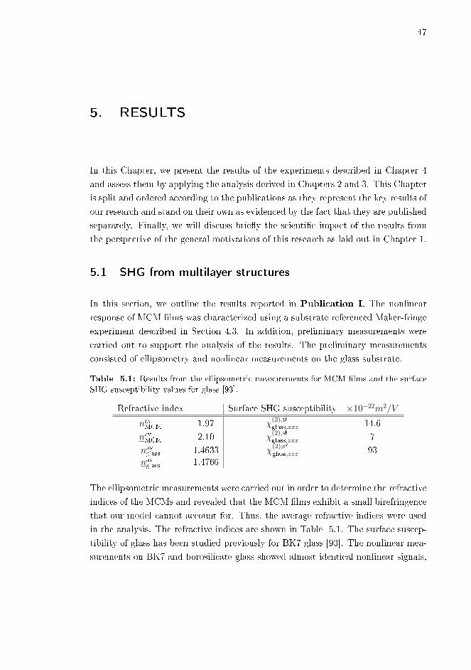
47
5. RESULTS
In this Chapter, we present the results of the experiments described in Chapter 4
and assess them by applying the analysis derived in Chapters 2 and 3. This Chapter
is split and ordered according to the publications as they represent the key results of
our research and stand on their own as evidenced by the fact that they are published
separately. Finally, we will discuss brie�y the scienti�c impact of the results from
the perspective of the general motivations of this research as laid out in Chapter 1.
5.1 SHG from multilayer structures
In this section, we outline the results reported in Publication I. The nonlinear
response of MCM �lms was characterized using a substrate referenced Maker-fringe
experiment described in Section 4.3. In addition, preliminary measurements were
carried out to support the analysis of the results. The preliminary measurements
consisted of ellipsometry and nonlinear measurements on the glass substrate.
Table 5.1: Results from the ellipsometric measurements for MCM �lms and the surfaceSHG susceptibility values for glass [93].
Refractive index Surface SHG susceptibility ×10−22m2/V
navMCM 1.97 χ(2),sfglass,xxz 14.6
navMCM 2.10 χ(2),sfglass,zxx 7
navglass 1.4633 χ(2),sfglass,zzz 93
navglass 1.4766
The ellipsometric measurements were carried out in order to determine the refractive
indices of the MCMs and revealed that the MCM �lms exhibit a small birefringence
that our model cannot account for. Thus, the average refractive indices were used
in the analysis. The refractive indices are shown in Table 5.1. The surface suscep-
tibility of glass has been studied previously for BK7 glass [93]. The nonlinear mea-
surements on BK7 and borosilicate glass showed almost identical nonlinear signals,

48 5. Results
indicating that the SHG susceptibility values of BK7 can be used for the borosilicate
substrates of our samples. The surface SHG susceptibility values of glass used for
the nonlinear characterization are shown in Table 5.1.
The Maker-fringe measurements were carried out for three MCM samples of 50 nm,
25 nm and 2.1 nm thickness fabricated on top of a borosilicate glass substrate. In
addition, a bare substrate was studied for reference. The results of the Maker-fringe
measurements are shown in (Fig. 5.1a), where the zero thickness refers to the bare
substrate. As expected, the increasing number of interfaces results in an increased
signal as the thickness grows. This is in line with our interpretation that the MCM
can be treated as an e�ective �lm with C∞v symmetry that is the same symmetry
possessed by the glass surface. Thus, using Eq. (3.14), it can be seen that SHG from
p polarized excitation is fully p polarized for both the MCM �lm and the substrate
surface. As a result, both the surface SHG susceptibility of glass and the e�ective
bulk SHG susceptibility of the MCM medium can be written as
χ(2)j = 2χ
(2)j,xxz cos θj sin θj cos θj + χ
(2)j,zxx sin θj cos θj cos θj
+ χ(2)j,zzz sin θj sin θj sin θj.
(5.1)
where j denotes MCM or glass. Furthermore, using Eq. (4.1), the total irradiance
is
I = q|EpMCM + Ep
glass|2, (5.2)
where q is a proportionality factor and with the SHG �eld from glass being [41,93]
Epglass =
ω2tp31(tp12)
2
c2(tp32)
2
wglass
χ(2)glasse
2iwglassDglass(Ep0)2. (5.3)
As discussed in Section 4.3, the re�ections occuring in the numerous layers of MCM
�lms are very di�cult to account for and are thus neglected. As a result, the SHG
�eld from the MCM �lm can be fully described by Eqs. (3.36 and 3.37). However, the
functional form can be simpli�ed further by noting that the samples are extremely
thin. Thus, by using Eq. (3.35), the phase mismatch factor can be approximated as
Φ ≈ iDMCM, yielding
EpMCM =
ω2tp31(tp12)
2
c2tp32
wMCM
DMCMχ(2)MCMe
iwglassDglass(Ep0)2. (5.4)

5.1. SHG from multilayer structures 49
Figure 5.1: a) Substrate referenced Maker-fringe experiment results from MCM �lmswith thickness of 50 nm - red diamonds, 25 nm - blue triangles 2.1 nm - green circles and0 nm - gray crosses deposited on a borosilicate glass substrate. The markers representexperimental data and the lines represent �tted curves. b) Maker-fringe measurementsfrom two samples attached to each other: Red - [ABC]-glass-glass-[CBA]; Blue - glass-[ABC]-[CBA]-glass; Gray - glass-glass. The �gure is based on the results of PublicationI.
Lastly, we note that it is extremely di�cult to separate the two o�-diagonal SHG
tensor components χxxz and χzxx using a Maker-fringe measurement with our polar-
ization con�guration unless the material shows extremely high dispersion. Indeed,
if the angles of incidence at the fundamental and SHG frequencies are identical
θ ≈ θ, the two o�-diagonal components are inseparable. Thus, we limit ourselves
to �tting the results using three free parameters: Azx = 2χ(2)MCM,xxz + χ
(2)MCM,zxx,
χ(2)MCM,zzz and the proportionality factor of Eq. (5.2). To connect the o�-diagonal
component to the SHG, Kleinman symmetry can be assumed to obtain an estimate
χ(2)MCM,xxz = χ
(2)MCM,zxx = Azx/3.
The results of the Maker-fringe experiments �tted using the above analysis are
shown in (Fig. 5.1a). The acquired values for the studied SHG components for the
25 nm and 50 nm thick MCMs are shown in Table 5.2. The 2.1 nm thick MCM
was omitted due to the fact that we cannot verify whether the glass SHG or the
MCM SHG dominates since the signal level is too close to the one from the bare
substrate. The discrepancy between the acquired values for o�-diagonal component
Azx is most likely due to the approximations and due to the signal being dominated
by the diagonal component χ(2)zzz. Taking the above into account, we feel that it is
safe to report a value of the dominant component χ(2)zzz of 5± 2 pm/V.
Lastly, to verify that the observed nonlinearity is of bulk origin, we also measured
SHG from glass-[ABC]-[CBA]-glass and [ABC]-glass-glass-[CBA] structures, and

50 5. Results
Table 5.2: Separable SHG component values determined for MCM �lms of 25 nm and50 nm thickness using substrate referenced Maker-fringe experiment.
25 nm MCM 50 nm MCM
Azx 1.44± 0.16 pm/V 0.78± 0.07 pm/Vχ(2)zzz 6.0± 0.8 pm/V 6.1± 0.4 pm/V
compared the signal to that from two substrates put together. Results of these
experiments are shown in (Fig. 5.1b). SHG from the glass-[ABC]-[CBA]-glass sam-
ple is almost as weak as that of the double substrate. This is expected for bulk
nonlinearity since the [ABC]-[CBA] system has a center of inversion in the middle.
On the other hand, the dispersion in the thick glass layer allows for much higher
SHG with a smaller period of oscillation for the [ABC]-glass-glass-[CBA] case, and
the imperfect visibility is explained by the temporal walko� of the short femtosecond
pulses. To summarize, these �ndings support the interpretation of the MCM �lm
behaving like a e�ective bulk �lm.
In conclusion, we demonstrated high SHG nonlinearity of the order of 5± 2 pm/V
for the dominant tensor component from our MCM �lms. This value is comparable
to many common nonlinear materials [6]. As such, our results strongly support
the proof of concept reported in Ref. [40] of multilayer structures as an e�ective
new type of nonlinear material, for example, for use in conjunction with CMOS-
compatible photonic components. Lastly, we note that the optimization could be
taken further by increasing the refractive index contrast between the three materials
or by fabricating thinner constituent layers, resulting in even higher nonlinearity [70].
5.2 Multipolar SHG from thin �lms
In this section, we outline the results reported in Publication II. In order to
characterize the presence of MP SHG nonlinearity, we expanded the traditional
two-beam method derived for thick samples to thin �lms and tested it for a SiN
thin �lm. Preliminary experiments were unnecessary, since we used the SiN thin
�lm from Ref. [71]. Thus, the SiN thin �lm was known to exhibit C∞v symmetry,
have thickness of D = 800 nm and refractive indices of n = 1.94 and n = 1.99 for
the fundamental and SHG wavelengths, respectively [71]. Lastly, the SHG signal
from the SiN �lm is su�ciently strong so that SHG from the glass substrate could
be neglected.

5.2. Multipolar SHG from thin �lms 51
The traditional two-beam approach is based on the fact that by studying the s
polarized SHG generated jointly from two non-collinear beams with particular po-
larizations, the MP contribution to the signal governed by δ′ can be separated from
the ED contribution to the signal governed by χ(2)xxz [64, 66, 85, 127]. The method
is based on the unique determination of polarization signatures f s,p,s and f s,s,p and
solving their relationship with ED and MP contribution.
Although the above method was developed for thick samples where re�ections can
be largely ignored, the result holds qualitatively for thin �lms as well. Indeed, by
using Eq. (3.55) with Es ∝ f s,p,sEpa,0E
sb,0 + f s,s,pEs
a,0Epb,0 the relationship between
the polarization signatures can be written as[f s,p,s
f s,s,p
]=
[u11 u12
u21 u22
][χ(2)xxz
kδ′
], (5.5)
where the matrix elements are given by (see Section 3.3 for notation)
u11 = 2F sin θa∑β,γ
(Φ′−βγ + r21Φ′+βγ)K
pa,βK
sb,γ (5.6)
u12 = iF∑β,γ
(Φ′−βγ + r21Φ′+βγ)K
pa,βK
sb,γsign(γ) sin [θa − sign(β)sign(γ)θb] (5.7)
u21 = 2F sin θb∑β,γ
(Φ′−βγ + r21Φ′+βγ)K
sa,βK
pb,γ (5.8)
u22 = −iF∑β,γ
(Φ′−βγ + r21Φ′+βγ)K
sa,βK
pb,γsign(γ) sin [θa − sign(β)sign(γ)θb] , (5.9)
with sign(i) = ±1 for i = ± and
F = eiwDω2ts23C
s
2cw. (5.10)
If re�ection-related e�ects are ignored, i.e., all the Fresnel re�ection coe�cients are
set to zero, the matrix elements in Eqs. (5.6-5.9) become
u11 = 2F ′ sin θatpa,12t
sb,12 (5.11)
u12 = −iF ′tpa,12tsb,12 sin(θa − θb) (5.12)
u21 = 2F ′ sin θbtsa,12t
pb,12 (5.13)
u22 = iF ′tsa,12tpb,12 sin(θa − θb), (5.14)

52 5. Results
Figure 5.2: Simulations and results of two-beam polarization controlled experimentfrom a SiN thin �lm. a)-c): Simulation for the case a) without MP SHG and neglectingre�ections, b) with 10% MP contribution to SHG and neglecting re�ections and c) withoutMP SHG with re�ections taken into account. d)-f): Experimental results (markers), �tted(lines) with d) no MP contribution allowed and neglecting re�ections, e) MP contributionallowed and neglecting re�ections (predicted MP contribution: 7%) and f) MP contributionallowed and re�ections taken into account (predicted MP contribution: 0%). Dashed linesare guides for eyes only. The �gure is based on the results of Publication II.
with
F ′ = eiwDω2ts23Φ
′−,−,−
2cw, (5.15)
which is almost identical to the thick sample case [67]. The important thing to note
here is that the phase di�erence between f s,p,s and f s,s,p and the resulting signature
in the measured signal arises exclusively from the MP parameter [64]. Simulations
of this signature for a case without (a) and with (b) MP contribution are shown in
(Fig. 5.2a and Fig. 5.2b). However, if the re�ections are properly accounted for
and Eqs. (5.6-5.9) are used, a phase di�erence between f s,p,s and f s,s,p is present
even without a MP contribution. This situation is simulated in (Fig. 5.2c) with the
dashed lines being guides for the eye to indicate the peak heights in the graph. A
di�erence in peak heights is evidence of either MP contribution or a phase di�erence
originating from something else, such as re�ections.
5.3. SHG from InSe thin �lms 53
The �ndings were veri�ed experimentally by studying our SiN �lm with a polariza-
tion-controlled two-beam experiment discussed in Chapter 4, and �tting the results
both by neglecting re�ections and by taking them fully into account. The results
are shown in (Fig. 5.2d-f). The results were �tted by neglecting re�ections and
allowing only ED contribution (Fig. 5.2d), by neglecting re�ections and allowing
both ED and MP contributions (Fig. 5.2e) and by taking the re�ections into account
and allowing both ED and MP contribution (Fig. 5.2f). As expected, there is no
peak height di�erence without re�ections nor MP contribution (Fig. 5.2d) and the
analysis predicts 7%MP contribution if they are allowed and re�ections are neglected
(Fig. 5.2e). However, if the re�ections are taken into account, the analysis yields
essentially zero MP contribution and the phase di�erence is completely explained
by ED SHG and re�ections.
In summary, we have extended the analytical treatment of MP two-beam SHG
from thick material systems to thin �lms with thicknesses of the order of optical
wavelengths. The most important di�erence between the models is the presence of
re�ection-based phenomena, which must be taken into account. We showed theo-
retically and experimentally that neglecting these e�ects will result in qualitatively
erroneous results outside the case of a dominating multipolar contribution and quan-
titatively erroneous results for all cases. We highlight that even though this analysis
was conducted for the case with nonvanishing bulk-type dipolar SHG response, our
result still holds for thin �lm samples where the dipolar SHG response is limited to
the surfaces.
5.3 SHG from InSe thin �lms
In this section, we outline the results reported in Publication III. The characteri-
zation of the nonlinear response of InSe �lms was carried out using a method almost
identical to the one used for MCM �lms. Thus, the analysis follows closely to the
analysis presented in Section 5.1. Preliminary measurements included ellipsometry
for the determination of refractive indices and preliminary nonlinear polarization
experiments to verify in-plane isotropy of the �lms.
The ellipsometric measurements revealed that the InSe �lms exhibit signi�cant ab-
sorption at the SHG wavelength, which can be represented with a complex refrac-
tive index. The obtained refractive indices were n = 2.63 and n = n′ + in′′, with
n′ = 3.02 and n′′ = 0.28 for the fundamental and SHG frequencies, respectively.

54 5. Results
Due to the real parts of the refractive indices being extremely high, the propaga-
tion angles within the �lm remain relatively small even for large angles of incidence.
As a result, the sines of the propagation angles are also small. The contribution
from χ(2)zzz depends on three sine factors (see Eq. 5.1), and can thus be neglected.
As a result, following the reasoning of Section 5.1, the only experimentally sepa-
rable SHG component is Azx = 2χ(2)xxz + χ
(2)zxx. Once more, the o�-diagonal SHG
susceptibility components can be estimated by assuming Kleinman symmetry as
χ(2)MCM,xxz = χ
(2)MCM,zxx = Azx/3.
The Maker-fringe measurements were carried out for three InSe thin �lms of 40
nm, 100 nm and 190 nm thickness and the results are shown in (Fig. 5.3). As
stated above, the analysis follows closely to what was used for MCM �lms. Here, we
neglect phase-mismatched beams and consider only the forward phase-matched SHG
(Φ−−−), but we do account for re�ections by including etalon coe�cients (Cp)2 and
Cp at fundamental and SHG frequency, respectively. We also account for absorption
by rewriting the z component of the wave vector at SHG frequency as w → w′ =
w + iα, with α = (ωn′′)/(c cos θ). Now, the SHG �elds from InSe and glass can be
written as
EpInSe =
ω2tp31(tp12)
2
c2tp32w′InSe
(Cp)2CpΦ−−−χ(2)InSee
iwglassDglass(Ep0)2 (5.16)
and
Epglass =
ω2tp31(tp12)
2
c2(tp32)
2
wglass
(Cp)2χ(2)glasse
2iwglassDglass(Ep0)2, (5.17)
with χ(2)InSe containing only the Azx term, χ(2)
glass term being given by Eq. (5.1), and
the total SHG irradiance given by Eq. (5.2). The SHG components obtained from
the �tting process for the three samples are Azx = 2.9 ± 0.4 pm/V for 40 nm,
Azx = 4.0±0.5 pm/V for 100 nm, Azx = 4.1±0.5 pm/V for 190 nm. We believe that
the disagreement of the SHG component value obtained for the 40 nm thick �lm with
the ones obtained for the 100 nm and 190 nm �lms is due to the neglect of the phase-
mismatched SHG. While this contribution is generally relatively small compared to
the forward generated SHG, for a sample as thin as 40 nm its contribution may play a
larger role. Thus, we believe that the strong agreement between the values obtained
for the 100 nm and 190 nm �lms indicates that those values better represent reality.
To summarize, we performed nonlinear Maker-fringe characterization for InSe thin
�lms. The obtained value for the dominant SHG component was of the order of

5.4. Tuning SHG from SiN by material composition 55
Figure 5.3: Results of the Maker-fringe experiment on InSe thin �lms of 40 nm (green),100 nm (blue) and 190 nm (red) thicknesses. Markers denote the measurement points andthe lines denote �tting curves. The �gure is based on the results of Publication III.
4 pm/V, a value that is of the same order with many nonlinear crystals [6]. Although
the third-order nonlinearity is common in chalcogenide glasses [111, 128], second-
order e�ects being forbidden under centrosymmetry are much less common. As
such, amorphous InSe, especially considering the cost-e�ectiveness of the fabrication,
could well be an interesting material for photonic applications.
5.4 Tuning SHG from SiN by material composition
In this section, we outline the results reported in Publication IV. The nonlinear
characterization of SiN thin �lms was carried out using quartz referenced polariza-
tion controlled experiment as described in Section 4.4. Five thin �lms, labeled S10,
S20, S30, S35 and S40, of di�erent material composition were studied. The sym-
metry of the samples was tested with preliminary nonlinear polarization mapping
that indicated a C∞v symmetry, as expected [71]. The refractive indices at the fun-
damental and SHG frequencies as well as exact thicknesses were determined using
ellipsometry for all �ve samples. The ellipsometric results are shown in Table 5.3.
The results of the polarization controlled experiment for the di�erent polarization
combinations of the initial excitation beam and the detected SHG beam are shown
in (Fig. 5.4). The results were analysed by using Eq. (4.2) in conjunction with
Eqs. (3.14 and 3.41). As a result, the relationship between the polarization signa-

56 5. Results
Table 5.3: Results from the ellipsometric measurements for SiN �lms. For each �lm,thickness and refractive indices both at fundamental and SHG frequency were determined.
Sample D (nm) n n
S10 662 2.174 + 0.002i 2.354 + 0.022iS20 604 2.005 + 0.000i 2.099 + 0.007iS30 537 1.945 + 0.000i 1.989 + 0.002iS40 500 1.969 + 0.000i 2.027 + 0.002iS50 505 1.902 + 0.000i 1.951 + 0.001i
tures and the nonvanishing SHG tensor components was found to be
fp,p,p
fp,s,s
fp,p,s + fp,s,p
f s,p,p
f s,s,s
f s,p,s + f s,s,p
=
u11 u12 u13 u14 u15 u16 u17
u21 u22 u23 u24 u25 u26 u27
u31 u32 u33 u34 u35 u36 u37
u41 u42 u43 u44 u45 u46 u47
u51 u52 u53 u54 u55 u56 u57
u61 u62 u63 u64 u65 u66 u67
χ(2)xxz
χ(2)xzx
χ(2)yyz
χ(2)yzy
χ(2)zxx
χ(2)zyy
χ(2)zzz
, (5.18)
with
uξτ = eiwDω2
2c2wtξ23∑φβγ
Lξ,τ,φχ(2)τ ΦφβγLξ,τ,βLξ,τ,γK
ξφK
τβK
τγ , (5.19)
where ξ and τ are the indices of permutations of ζ, η, κ ∈ {p, s} and permutations
of i, j, k ∈ {x, y, z}, i.e., indices of the vectorizations f and χ(2)V in Eq. (4.2), respec-
tively. The particular choice of this indexing is arbitrary; for example, our choice
in Eq. (5.18) has ξ = 2 ↔ (p, s, s) and τ = 3 ↔ (y, y, z), since u23 describes the
relationship between fp,s,s and χ(2)yyz.
By examining Eq. (5.19) and combining the non-independent SHG tensor compo-
nents, Eq. (5.18) can be written as fp,p,p
fp,s,s
f s,s,p + f s,p,s
=
m′11 m′12 m′130 m′22 0
m′31 0 0
χ
(2)xxz
χ(2)zxx
χ(2)zzz
, (5.20)

5.4. Tuning SHG from SiN by material composition 57
Figure 5.4: a)-e) The results from the polarization controlled measurements for samplesa) S10, b) S20, c) S30, d) S35 and e) S40. The polarization combinations of the initialexcitation beam and the detected SHG beam are: Black - (p + s)/
√2 in, p out; Blue -
(p+ s)/√2 in, (p+ s)/
√2 out; Red - (p− s)/
√2 in, p out; Green: (p− s)/
√2 in, (p+ s)/
√2
out. f) An example of the calibration measurement of sample S30, which was subsequentlycompared to SHG from quartz. The �gure is based on the results of Publication IV.
with
u′11 = u11 + u12 (5.21)
u′12 = u15 (5.22)
u′13 = u17 (5.23)
u′22 = u26 (5.24)
u′31 = u33 + u34, (5.25)
where the matrix elements can be calculated using Eq. (5.19) and the remaining
polarization signatures can be uniquely solved with our measurement scheme as
discussed in Section 4.4. In order to obtain the SHG tensor structure of SiN, the four
polarization controlled measurements can be �tted simultaneously to the relative
tensor components and a scaling factor using the above analysis.
For the calibration with respect to quartz, the p polarized SHG arising from s polar-
ized excitation was measured with varying angle of incidence. Only χ(2)zxx contributes

58 5. Results
to the generated SHG, as governed by m′22, and the SHG �eld can be written as
EpSiN = tp31u26(E
s0)2, (5.26)
which can then be compared to SHG from quartz. Using Eq. (3.36) with perpen-
dicular incidence, polarizations of the excitation beam and the detected SHG beam
being parallel to the X axis of the quartz, neglecting re�ections and maximizing the
phase-matching (Φ−−− = 2/(w − 2w)), the SHG from quartz is given by
EpQ =
tp21(tp12)
2
nQ(nQ − 2nQ)χ(2)Q,XXX(Ep
0)2. (5.27)
The absolute value of χ(2)zxx can now be obtained with respect to the known SHG
susceptibility of quartz χ(2)Q,XXX = 0.80 pm/V [129]. The neglect of re�ections for
quartz measurement is justi�ed by the thickness and wedged shape of the crystal,
making the assumption of in�nite re�ections unphysical. The SHG susceptibility
tensor components obtained with the above analysis in conjunction with the polar-
ization controlled experiment are shown in Table 5.4.
Table 5.4: Results from the nonlinear measurements for SiN �lms. For each �lm, theSHG tensor structure was determined by a polarization controlled experiment and theabsolute SHG tensor values were calibrated by the quartz reference experiment.
Sample χ(2)xxz (pm/V) χ
(2)zxx (pm/V) χ
(2)zzz (pm/V)
S10 1.60 1.40 5.10S20 0.87 0.72 1.70S30 0.40 0.34 1.10S40 0.20 0.21 0.66S50 0.23 0.22 0.80
In conclusion, we conducted a full tensorial characterization of SiN thin �lms with
varying composition. The SHG response was found to increase by as much as 6-fold
with increasing silicon content. The highest SHG susceptibility component of χ(2)zzz =
5.10 pm/V is once again comparable to well-known nonlinear materials, highlighting
the potential applicability of SiN especially considering its CMOS compatibility. In
addition, the PECVD method was found to produce extremely high-quality samples
consistenty, which is useful from the characterization perspective. To answer the
question about the microscopic origin of the bulk nonlinearity, proposed theories
including intrinsic strain introduced in the fabrication process, presence of static
�elds and formation of small nanocrystals could be further studied for example

5.5. Non-resonant enhancement of SHG from metal-dielectric composites 59
by studying the e�ects of external strain on the SHG response, by an external
application of a static �eld on the �lm or by di�raction techniques, respectively.
5.5 Non-resonant enhancement of SHG from metal-dielectric
composites
In this section, we outline the results reported in Publication V. The nonlinear
responses from the gold nanoisland �lms coated with TiO2 were estimated using a
substrate-referenced Maker-fringe experiment. The purpose of this experiment was
to study the dependence of the local-�eld enhancement of the nonlinearity on the
coating thickness. To support our analysis, absorption spectra were measured using
a spectrophotometer.
The absorption spectra and results from Maker-fringe measurements are shown in
(Fig. 5.5a) and (Fig. 5.5b), respectively. The relative SHG signals from the coated
�lms were estimated from the visibility of the fringes using the scalar approximation
of Eq. (4.1) and by assuming that one of the sources, e.g., the back surface of the
substrate, is common for all samples. The resulting relative SHG signal values are
shown in (Fig. 5.5c).
To analyze the results, the local �eld factors describing the relative enhancement of
the electric �eld were calculated using a numerical model for a truncated nanosphere
coated by TiO2. The details of the modeling are reported in Refs. [130�132]. These
local �eld factors can be connected to the enhancement of SHG as [133]
ISHG =∝ JJ2, (5.28)
where J and J are the local �eld factors at the fundamental and SHG frequencies,
respectively. The SHG enhancement predicted by the model is shown in (Fig. 5.5d)
and the individual local �eld factors at the fundamental and SHG frequencies are
shown in the inset of (Fig. 5.5d). We note that while the thickness dependence is
well explained by the model, the absolute magnitude of the enhancement predicted
by the model di�ered from the observed enhancement. We believe that this is mostly
due to the size distribution of the nanoparticles.
To conclude, we studied SHG response of gold nanoisland �lms coated with various
thicknesses of TiO2 using a Maker-fringe experiment under the scalar approxima-

60 5. Results
Figure 5.5: a) Absorption spectra of gold nanoisland �lms coated with di�erent thick-nesses of TiO2. b) Maker-fringe measurement results for the said �lms. c) Estimated SHGsignal levels from the said �lms. d) Numerically calculated total local �eld enhancementfor said �lms. Inset: Numerically calculated local-�eld factors at the fundamental andSHG frequencies. The �gure is based on the results of Publication V.
tion. Firstly, we showed that coating of nanoparticles a�ects the absorption spectra
depending on the coating thickness. Secondly, we showed both experimentally and
numerically that despite the detuning of the resonance with respect to the SHG
frequency and thus weakening of the local-�eld factor at SHG frequency, the en-
hancement of the local-�eld factor at fundamental frequency can dominate the total
contribution to SHG. To our understanding, such non-resonant enhancement has
not been reported previously outside our research and is not limited to this context,
possibly opening new ways to optimize nanostructures.

61
6. CONCLUSIONS
In this Thesis, we developed a thorough analytical model to treat second-harmonic
generation from material systems of sub-wavelength thickness both for the case of a
single excitation beam and for the case of two non-collinear excitation beams. The
model was successfully applied to various traditional methods in the characterization
of several potential nonlinear materials: Multilayer composite �lms, silicon nitride,
indium selenide and metal-dielectric composites.
This work was motivated by the ongoing search for novel nonlinear materials for
di�erent optical applications. Indeed, many of the applications in, for example,
the �eld of integrated photonics rely on nonlinear phenomena. Many of these phe-
nomena are elusive by nature, few more so than second-harmonic generation, and
thus potential materials are few and far in between. With the ever-growing interest
towards the miniaturization of optical devices driven by the advances in nanopho-
tonics, the need for expanding the range of applicable nonlinear materials has never
been more compelling.
In pursuit of our goal, we demonstrated the potential of silicon nitride and indium
selenide as novel second-order nonlinear materials with a second-harmonic response
of the order comparable to traditional nonlinear crystals. In addition, the �exibility
of the physical parameters of indium selenide allows for further optimization and
the CMOS compatibility of silicon nitride is highly advantageous with the material
needs of nanophotonics in mind. Our results also show that multilayered composite
materials consisting of numerous extremely thin centrosymmetric dielectric layers
can circumvent the non-centrosymmetry requirement of second-harmonic generation
e�ectively and exhibit competitive second-harmonic responses.
Lastly, methods to further improve existing strong second-harmonic response were
explored. We reported a six-fold increase in the second-harmonic susceptibility of
silicon nitride by tuning the material composition via the fabrication process, as
well as a 40-fold enhancement in the second-harmonic response of gold nanoparticle

62 6. Conclusions
�lms coated with titanium dioxide by tuning the coating thickness.
In addition to its utility in the analysis of experimental results, the derivation of
the analytical model itself works towards our objectives. The general nature of the
model ensures that it can be used for the treatment of second-harmonic generation
from any thin layer, as evidenced by its wide usage in the various experimental
schemes of this work. The main advantage of the model compared to the common
approaches is the full inclusion of re�ections for the cases of single- and two-beam
excitations in thin layers in conjunction with the aforementioned generality. Re-
�ections can often be and even more often are neglected for thick systems due to
the tedious calculus associated with their inclusion. However, for thin systems, it
is absolutely paramount that they are accounted for as the failure to do so will re-
sult in both quantitative and qualitative errors, as demonstrated for the separation
of multipolar SHG in this work. In addition, great attention was given to writ-
ing the model in a compact form with parameters clearly associated with physical
phenomena. Particularly, the model explicitly addresses the relationship between
the experimental polarization signatures and the SHG susceptibility tensor, allow-
ing for a speci�c design of experiments, analysis of any kind of experiment as well
as optimization of SHG by the geometrical design for thin systems. Thus, we be-
lieve that our theoretical work is invaluable for any researcher attempting to treat
second-harmonic generation process in thin layers.
Despite the results of this Thesis, no work is ever complete. Besides the obvious
trials for new materials, continuation of this work might involve a more thorough
nonlinear characterization of multilayer structures and gold-titanium dioxide com-
posites, broadening the experimental methodology and further expansion of the
analytical model. Nonlinear materials transparent in the ultraviolet region such as
certain plastics would be especially interesting due to most materials being opaque
for ultraviolet light.
The characterization of multilayer structures and gold-titanium dioxide compos-
ites could be expanded by conducting a full polarization-controlled experiment to
complement the current results. Such an experiment could address all of the suscep-
tibility tensor components and improve the accuracy of the results. This is especially
true for the gold-titanium dioxide composites given the simplicity of their analysis.
However, great care should be taken to account for the non-negligible SHG from
the back surface of the substrate as it is di�cult to account for this using only a

63
polarization-controlled scheme. A potential solution would be to analyse both a
Maker-fringe experiment and a polarization-controlled experiment simultaneously.
An alternative would be to fabricate thicker samples that produce more SHG so
that the SHG from the substrate would become negligible.
The main ways to improve the experimental methodology would be to utilize a
range of excitation frequencies for the nonlinear characterization or to introduce
ways to control several parameters simultaneously in the experiment. The former is
far more ambitious, as it requires a tunable source, achromatic optics and a detec-
tor capable of detecting a su�ciently wide spectrum of SHG with high sensitivity.
However, the bene�ts of studying the spectral behaviour of the nonlinear suscep-
tibility would provide great insights on the material nonlinearity and its origins.
The latter option of introducing simultaneous control is considerably easier to im-
plement as, besides some minor practical challenges, a modest �nancial investment
and an updated automatization algorithm are all that are required. The main ben-
e�t aside from the convenience of the researcher is that the simultaneous control of
the polarizations and the angle of incidence would allow for a more reliable joint
Maker-fringe/polarization-controlled experiments.
Lastly, the analytical model could be further expanded in a variety of ways. Firstly,
the full description of the total multipolar SHG could be derived as opposed to
the signature-of-presence -approach used in this work. The derivation of the said
expressions would be a straightforward but tedious process, perhaps one suitable for
a M.Sc. thesis project. Secondly, the model could be expanded to systems of multiple
thin nonlinear layers. This problem is less straightforward, since the complexity of
the treatment of the interplay of re�ections grows rapidly if the approach presented
in this work is used. A good alternative might be to use some variation of the
transfer matrix formalism, although the exact details would have to be assessed.
Lastly, the model could be expanded to higher-order nonlinear e�ects such as third-
harmonic generation. Once more, this should be a relatively straightforward task
given the obvious analogies between second- and third-harmonic generation with
one of the greatest challenges possibly being running out of letters to denote the
indices present in the formulae.

64 6. Conclusions

65
REFERENCES
[1] S. Clemmen, A. Hermans, E. Solano, J. Dendooven, K. Koskinen, M. Kaura-
nen, E. Brainis, C. Detavernier, and R. Baets, �Atomic layer deposited second-
order nonlinear optical metamaterial for back-end integration with CMOS-
compatible nanophotonic circuitry,� Opt. Lett. 40, 5371�5374 (2015).
[2] K. Koskinen, R. Czaplicki, T. Kaplas, and M. Kauranen, �Recognition of mul-
tipolar second-order nonlinearities in thin-�lm samples,� Opt. Express 24,
4972�4978 (2016).
[3] K. Koskinen, A. Slablab, S. Divya, R. Czaplicki, S. Chervinskii, M. Kailasnath,
P. Radhakrishnan, and M. Kauranen, �Bulk second-harmonic generation from
thermally evaporated indium selenide thin �lms,� Opt. Lett. 42, 1076�1079
(2017).
[4] K. Koskinen, R. Czaplicki, A. Slablab, T. Ning, A. Hermans, B. Kuyken,
V. Mittal, G. S. Murugan, T. Niemi, R. Baets, and M. Kauranen, �Enhance-
ment of bulk second-harmonic generation from silicon nitride �lms by material
composition,� Opt. Lett. 42, 5030�5033 (2017).
[5] S. Chervinskii, K. Koskinen, S. Scherbak, M. Kauranen, and A. Lipovskii,
�Nonresonant local �elds enhance second-harmonic generation from metal
nanoislands with dielectric cover,� Phys. Rev. Lett. 120, 113902 (2018).
[6] R. W. Boyd, Nonlinear Optics (Academic Press, San Diego, 2008), 3rd ed.
[7] A. L. Schawlow and C. H. Townes, �Infrared and optical masers,� Physical
Review 112, 1940 (1958).
[8] P. A. Franken, A. E. Hill, C. W. Peters, and G. Weinreich, �Generation of
optical harmonics,� Physical Review Letters 7, 118�119 (1961).
[9] R. W. Terhune, P. D. Maker, and C. M. Savage, �Optical harmonic generation
in calcite,� Physical Review Letters 8, 404 (1962).
[10] B. Lax, J. G. Mavroides, and D. F. Edwards, �Nonlinear interband and plasma
e�ects in solids,� Physical Review Letters 8, 166 (1962).

66 REFERENCES
[11] J. Ducuing and N. Bloembergen, �Observation of re�ected light harmonics
at the boundary of piezoelectric crystals,� Physical Review Letters 10, 474
(1963).
[12] F. Brown, R. E. Parks, and A. M. Sleeper, �Nonlinear optical re�ection from
a metallic boundary,� Physical Review Letters 14, 1029 (1965).
[13] N. Bloembergen, R. K. Chang, and C. Lee, �Second-harmonic generation of
light in re�ection from media with inversion symmetry,� Physical Review Let-
ters 16, 986 (1966).
[14] C. C. Wang and A. N. Duminski, �Second-harmonic generation of light at
the boundary of alkali halides and glasses,� Physical Review Letters 20, 668
(1968).
[15] N. I. Adams and P. B. Schoefer, �Continuous optical sum frequency genera-
tion,� Proceedings of the IEEE 51, 1366�1367 (1963).
[16] C. C. Wang and G. W. Racette, �Measurement of parametric gain accom-
panying optical di�erence frequency generation,� Applied Physics Letters 6,
169�171 (1965).
[17] J. A. Armstrong, N. Bloembergen, J. Ducuing, and P. S. Pershan, �Interactions
between light waves in a nonlinear dielectric,� Physical Review 127, 1918�1939
(1962).
[18] Y. Shen, The Principles of Nonlinear Optics, ISBN: 978-0-471-43080-3 (Wiley-
Interscience, 1984).
[19] G. B. Arfken, H. J. Weber, and F. E. Harris, Mathematical Methods For Physi-
cists International Student Edition (Academic Press, 2005).
[20] G. D. Boyd, R. C. Miller, K. Nassau, W. L. Bond, and A. Savage, �LiNbO3: an
e�cient phase matchable nonlinear optical material,� Applied Physics Letters
5, 234�236 (1964).
[21] R. L. Byer, H. Kildal, and R. S. Feigelson, �CdGeAs2 � a new nonlinear crystal
phasematchable at 10.6 µm,� Applied Physics Letters 19, 237�240 (1971).
[22] R. C. Miller, �Optical second harmonic generation in piezoelectric crystals,�
Applied Physics Letters 5, 17�19 (1964).

REFERENCES 67
[23] J. L. Oudar and R. Hierle, �An e�cient organic crystal for nonlinear optics:
methyl-(2, 4-dinitrophenyl)-aminopropanoate,� Journal of Applied Physics 48,
2699�2704 (1977).
[24] B. F. Levine, C. G. Bethea, C. D. Thurmond, R. T. Lynch, and J. L. Bernstein,
�An organic crystal with an exceptionally large optical second-harmonic co-
e�cient: 2-methyl-4-nitroaniline,� Journal of Applied Physics 50, 2523�2527
(1979).
[25] J. Zyss, D. S. Chemla, and J. F. Nicoud, �Demonstration of e�cient nonlinear
optical crystals with vanishing molecular dipole moment: Second-harmonic
generation in 3-methyl-4-nitropyridine-1-oxide,� The Journal of Chemical
Physics 74, 4800�4811 (1981).
[26] M. Kauranen, T. Verbiest, J. Maki, and A. Persoons, �Second-harmonic gener-
ation from chiral surfaces,� The Journal of Chemical Physics 101, 8193�8199
(1994).
[27] Y. R. Shen, �Surface properties probed by second-harmonic and sum-frequency
generation,� Nature 337, 519�525 (1989).
[28] R. M. Corn and D. A. Higgins, �Optical second harmonic generation as a probe
of surface chemistry,� Chemical Reviews 94, 107�125 (1994).
[29] K. L. Sly, S.-W. Mok, and J. C. Conboy, �Second harmonic correlation spec-
troscopy: a method for determining surface binding kinetics and thermody-
namics,� Analytical Chemistry 85, 8429�8435 (2013).
[30] K. D. Singer, J. E. Sohn, and S. J. Lalama, �Second harmonic generation in
poled polymer �lms,� Applied Physics Letters 49, 248�250 (1986).
[31] W. Margulis and U. Österberg, �Second-harmonic generation in optical glass
�bers,� Journal of the Optical Society of America B 5, 312�316 (1988).
[32] R. A. Myers, N. Mukherjee, and S. R. J. Brueck, �Large second-order nonlin-
earity in poled fused silica,� Optics Letters 16, 1732�1734 (1991).
[33] C. Fiorini, F. Charra, J.-M. Nunzi, and P. Raimond, �Quasi-permanent all-
optical encoding of noncentrosymmetry in azo-dye polymers,� Journal of the
Optical Society of America B 14, 1984�2003 (1997).

68 REFERENCES
[34] F. Timpu, A. Sergeyev, N. R. Hendricks, and R. Grange, �Second-harmonic
enhancement with mie resonances in perovskite nanoparticles,� ACS Photonics
4, 76�84 (2017).
[35] S. Liu, M. B. Sinclair, S. Saravi, G. A. Keeler, Y. Yang, J. Reno, G. M. Peake,
F. Setzpfandt, I. Staude, T. Pertsch et al., �Resonantly enhanced second-
harmonic generation using iii�v semiconductor all-dielectric metasurfaces,�
Nano letters 16, 5426�5432 (2016).
[36] R. S. Jacobsen, K. N. Andersen, P. I. Borel, J. Fage-Pedersen, L. H. Frandsen,
O. Hansen, M. Kristensen, A. V. Lavrinenko, G. Moulin, H. Ou, C. Peucheret,
B. Zsigri, and A. Bjarklev, �Strained silicon as a new electro-optic material,�
Nature 441, 199 EP � (2006).
[37] B. Chmielak, M. Waldow, C. Matheisen, C. Ripperda, J. Bolten,
T. Wahlbrink, M. Nagel, F. Merget, and H. Kurz, �Pockels e�ect based fully in-
tegrated, strained silicon electro-optic modulator,� Optics Express 19, 17212�
17219 (2011).
[38] M. Cazzanelli, F. Bianco, E. Borga, G. Pucker, M. Ghulinyan, E. Degoli,
E. Luppi, V. Veniard, S. Ossicini, D. Modotto, S. Wabnitz, R. Pierobon,
and L. Pavesi, �Second-harmonic generation in silicon waveguides strained by
silicon nitride,� Nature Materials 11, 148�154 (2012).
[39] I. R. Girling, S. R. Jethwa, R. T. Stewart, J. D. Earls, G. H. Cross, N. A.
Cade, P. V. Kolinsky, R. J. Jones, and I. R. Peterson, �Second-order non-linear
optical e�ects in Langmuir-Blodgett �lms,� Thin Solid Films 160, 355�362
(1988).
[40] L. Alloatti, C. Kieninger, A. Froelich, M. Lauermann, T. Frenzel, K. Köhnle,
W. Freude, J. Leuthold, M. Wegener, and C. Koos, �Second-order nonlinear
optical metamaterials: ABC-type nanolaminates,� Applied Physics Letters
107, 121903 (2015).
[41] M. Zdanowicz, J. Harra, J. M. Makela, E. Heinonen, T. Ning, M. Kauranen,
and G. Genty, �Second-harmonic response of multilayer nanocomposites of
silver-decorated nanoparticles and silica,� Scienti�c Reports 4, 5745 (2014).
[42] I. Russier-Antoine, E. Benichou, G. Bachelier, C. Jonin, and P. Brevet, �Mul-
tipolar contributions of the second harmonic generation from silver and gold
nanoparticles,� The Journal of Physical Chemistry C 111, 9044�9048 (2007).

REFERENCES 69
[43] A. E.-J. Lim, J. Song, Q. Fang, C. Li, X. Tu, N. Duan, K. K. Chen, R. P.-
C. Tern, and T.-Y. Liow, �Review of silicon photonics foundry e�orts,� IEEE
Journal of Selected Topics in Quantum Electronics 20, 405�416 (2014).
[44] M. S. Rill, C. Plet, M. Thiel, I. Staude, G. Von Freymann, S. Linden, and
M. Wegener, �Photonic metamaterials by direct laser writing and silver chem-
ical vapour deposition,� Nature Materials 7, 543 (2008).
[45] I. Staude and J. Schilling, �Metamaterial-inspired silicon nanophotonics,� Na-
ture Photonics 11, 274 (2017).
[46] A. Alduino and M. Paniccia, �Interconnects: Wiring electronics with light,�
Nature Photonics 1, 153 (2007).
[47] D. A. Miller, �Optical interconnects to silicon,� IEEE Journal of Selected Top-
ics in Quantum Electronics 6, 1312�1317 (2000).
[48] B. G. Lee, X. Chen, A. Biberman, X. Liu, I.-W. Hsieh, C.-Y. Chou, J. I.
Dadap, F. Xia, W. M. Green, L. Sekaric et al., �Ultrahigh-bandwidth silicon
photonic nanowire waveguides for on-chip networks,� IEEE Photonics Tech-
nology Letters 20, 398�400 (2008).
[49] G. Lifante, Integrated photonics: fundamentals (John Wiley & Sons, 2003).
[50] C. R. Pollock and M. Lipson, Integrated photonics, vol. 20 (Springer, 2003).
[51] R. L. Espinola, J. I. Dadap, R. M. Osgood, S. J. McNab, and Y. A. Vlasov,
�Raman ampli�cation in ultrasmall silicon-on-insulator wire waveguides,� Op-
tics Express 12, 3713�3718 (2004).
[52] R. M. Osgood, N. C. Panoiu, J. I. Dadap, X. Liu, X. Chen, I.-W. Hsieh,
E. Dulkeith, W. M. J. Green, and Y. A. Vlasov, �Engineering nonlinearities in
nanoscale optical systems: physics and applications in dispersion-engineered
silicon nanophotonic wires,� Advances in Optics and Photonics 1, 162�235
(2009).
[53] J. S. Levy, A. Gondarenko, M. A. Foster, A. C. Turner-Foster, A. L. Gaeta,
and M. Lipson, �CMOS-compatible multiple-wavelength oscillator for on-chip
optical interconnects,� Nature Photonics 4, 37�40 (2010).
[54] J. Leuthold, C. Koos, and W. Freude, �Nonlinear silicon photonics,� Nature
Photonics 4, 535 (2010).

70 REFERENCES
[55] P. Kultavewuti, �Nonlinear photonics in chip-based structures,� Frontiers in
Modern Optics 190, 171 (2016).
[56] L. Chang, Y. Li, N. Volet, L. Wang, J. Peters, and J. E. Bowers, �Thin �lm
wavelength converters for photonic integrated circuits,� Optica 3, 531�535
(2016).
[57] P. D. Maker, R. W. Terhune, M. Niseno�, and C. M. Savage, �E�ects of
dispersion and focusing on the production of optical harmonics,� Physical
Review Letters 8, 21�22 (1962).
[58] J. Jerphagnon and S. K. Kurtz, �Maker fringes: A detailed comparison of
theory and experiment for isotropic and uniaxial crystals,� Journal of Applied
Physics 41, 1667�1681 (1970).
[59] J. Sipe, V. Mizrahi, and G. Stegeman, �Fundamental di�culty in the use of
second-harmonic generation as a strictly surface probe,� Physical Review B
35, 9091�9094 (1987).
[60] W. N. Herman and L. M. Hayden, �Maker fringes revisited: second-harmonic
generation from birefringent or absorbing materials,� Journal of the Optical
Society of America B 12, 416�427 (1995).
[61] P. Pershan, �Nonlinear optical properties of solids: Energy considerations,�
Physical Review 130, 919�929 (1963).
[62] E. Adler, �Nonlinear optical frequency polarization in a dielectric,� Physical
Review 134, A728 (1964).
[63] P. Guyot-Sionnest and Y. Shen, �Bulk contribution in surface second-harmonic
generation,� Physical Review B 38, 7985�7989 (1988).
[64] S. Cattaneo and M. Kauranen, �Polarization-based identi�cation of bulk con-
tributions in surface nonlinear optics,� Physical Review B 72, 033412 (2005).
[65] S. Cattaneo and M. Kauranen, �Bulk versus surface contributions in nonlinear
optics of isotropic centrosymmetric media,� Physica Status Solidi (b) 242,
3007�3011 (2005).
[66] F. Rodriguez, F. Wang, B. Can�eld, S. Cattaneo, and M. Kauranen, �Multi-
polar tensor analysis of second-order nonlinear optical response of surface and
bulk of glass,� Optics Express 15, 8695�8701 (2007).

REFERENCES 71
[67] F. Rodríguez, F. Wang, and M. Kauranen, �Calibration of the second-order
nonlinear optical susceptibility of surface and bulk of glass,� Optics Express
16, 8704�8710 (2008).
[68] J. Sipe, �New Green-function formalism for surface optics,� The Journal of the
Optical Society of America B 4, 481�498 (1987).
[69] P. Guyot-Sionnest, W. Chen, and Y. Shen, �General considerations on optical
second-harmonic generation from surfaces and interfaces,� Physical Review B
33, 8254�8263 (1986).
[70] N. Bloembergen, R. Chang, S. Jha, and C. Lee, �Optical second-harmonic
generation in re�ection from media with inversion symmetry,� Physical Review
174, 813�822 (1968).
[71] T. Ning, H. Pietarinen, O. Hyvärinen, J. Simonen, G. Genty, and M. Kau-
ranen, �Strong second-harmonic generation in silicon nitride �lms,� Applied
Physics Letters 100, 161902 (2012).
[72] A. Segura, J. Bouvier, M. Andrés, F. Manjón, and V. Munoz, �Strong optical
nonlinearities in gallium and indium selenides related to inter-valence-band
transitions induced by light pulses,� Physical Review B 56, 4075 (1997).
[73] L. Debbichi, O. Eriksson, and S. Lebègue, �Two-dimensional indium selenides
compounds: An ab initio study,� The Journal of Physical Chemistry Letters
6, 3098�3103 (2015).
[74] M. Kauranen and A. V. Zayats, �Nonlinear plasmonics,� Nature Photonics 6,
737 (2012).
[75] J. Maxwell, A treatise on electricity and magnetism (Macmillan and Company,
London, 1873).
[76] J. D. Jackson, Classical Electrodynamics, ISBN: 978-0-471-30932-1 (Wiley,
New York, 1975), 2nd ed.
[77] E. Hecht, Optics (Addison Wesley, 2002), 4th ed.
[78] A. Perot and C. Fabry, �On the application of interference phenomena to the
solution of various problems of spectroscopy and metrology,� The Astrophys-
ical Journal 9, 87 (1899).

72 REFERENCES
[79] D. A. Kleinman, �Nonlinear dielectric polarization in optical media,� Physical
Review 126, 1977 (1962).
[80] R. D. Cowan, The Theory of Atomic Structure and Spectra (University of
California press, Berkeley, 1981).
[81] P. Guyot-Sionnest and Y. Shen, �Local and nonlocal surface nonlinearities for
surface optical second-harmonic generation,� Physical Review B 35, 4420�4426
(1987).
[82] M. Kauranen, T. Verbiest, and A. Persoons, �Second-order nonlinear optical
signatures of surface chirality,� Journal of Modern Optics 45, 403�424 (1998).
[83] P. Figliozzi, L. Sun, Y. Jiang, N. Matlis, B. Mattern, M. Downer, S. Withrow,
C. White, W. Mochan, and B. Mendoza, �Single-beam and enhanced two-beam
second-harmonic generation from silicon nanocrystals by use of spatially inho-
mogeneous femtosecond pulses,� Physical Review Letters 94, 047401 (2005).
[84] F. J. Rodríguez, F. X. Wang, B. K. Can�eld, S. Cattaneo, and M. Kaura-
nen, �Multipolar tensor analysis of second-order nonlinear optical response of
surface and bulk of glass,� Optics Express 15, 8695�8701 (2007).
[85] F. Wang, F. Rodríguez, W. Albers, R. Ahorinta, J. Sipe, and M. Kauranen,
�Surface and bulk contributions to the second-order nonlinear optical response
of a gold �lm,� Physical Review B 80, 233402 (2009).
[86] F. Wang, F. Rodríguez, W. Albers, and M. Kauranen, �Enhancement of bulk-
type multipolar second-harmonic generation arising from surface morphology
of metals,� New Journal of Physics 12, 063009 (2010).
[87] S. V. Andersen and K. Pedersen, �Second-harmonic generation from electron
beam deposited SiO �lms,� Optics Express 20, 13857�13869 (2012).
[88] R. Jing, Y. Guang, Z. Huidan, C. Guorong, K. Tanaka, K. Fujita, S. Murai,
and Y. Tsujiie, �Second-harmonic generation in thermally poled chalcohalide
glass,� Optics Letters 31, 3492�3494 (2006).
[89] M. Larciprete, A. Belardini, C. Sibilia, M.-b. Saab, G. Varo, and C. Gergely,
�Optical chirality of bacteriorhodopsin �lms via second harmonic maker's
fringes measurements,� Applied Physics Letters 96, 221108 (2010).

REFERENCES 73
[90] X. Zhang, J. Yao, W. Yin, Y. Zhu, Y. Wu, and C. Chen, �Determination of
the nonlinear optical coe�cients of the BaGa4Se7 crystal,� Optics Express 23,
552�558 (2015).
[91] J. Maki, M. Kauranen, T. Verbiest, and A. Persoons, �Uniqueness of wave-
plate measurements in determining the tensor components of second-order
surface nonlinearities,� Physical Review B 55, 5021�5026 (1997).
[92] F. Wang, M. Siltanen, and M. Kauranen, �Uniqueness of determination of
second-order nonlinear optical expansion coe�cients of thin �lms,� Physical
Review B 76, 085428 (2007).
[93] J. Maki, M. Kauranen, and A. Persoons, �Surface second-harmonic generation
from chiral materials,� Physical Review B 51, 1425�1434 (1995).
[94] M. Zdanowicz, J. Harra, J. M. Mäkelä, E. Heinonen, T. Ning, M. Kauranen,
and G. Genty, �Ordered multilayer silica-metal nanocomposites for second-
order nonlinear optics,� Applied Physics Letters 103, 251907 (2013).
[95] W. Shimizu, S. Nakamura, T. Sato, and Y. Murakami, �Creation of
high-refractive-index amorphous titanium oxide thin �lms from low-fractal-
dimension polymeric precursors synthesized by a Sol-Gel technique with a
hydrazine monohydrochloride catalyst,� Langmuir 28, 12245�12255 (2012).
[96] S. K. Kim, S. W. Lee, C. S. Hwang, Y. S. Min, J. Y. Won, and J. Jeong, �Low
temperature (< 100 ◦C) deposition of aluminum oxide thin �lms by ald with
o3 as oxidant,� Journal of The Electrochemical Society 153, F69 (2006).
[97] D. Beena, K. Lethy, R. Vinodkumar, A. Detty, V. M. Pillai, and V. Ganesan,
�Photoluminescence in laser ablated nanostructured indium oxide thin �lms,�
Journal of Alloys and Compounds 489, 215 � 223 (2010).
[98] A. Khanna, A. Z. Subramanian, M. Häyrinen, S. Selvaraja, P. Verheyen, D. V.
Thourhout, S. Honkanen, H. Lipsanen, and R. Baets, �Impact of ald grown
passivation layers on silicon nitride based integrated optic devices for very-
near-infrared wavelengths,� Optics Express 22, 5684�5692 (2014).
[99] A. Kitao, K. Imakita, I. Kawamura, and M. Fujii, �An investigation into second
harmonic generation by Si�rich SiN x thin �lms deposited by rf sputtering over
a wide range of si concentrations,� Journal of Physics D: Applied Physics 47,
215101 (2014).

74 REFERENCES
[100] E. F. Pecora, A. Capretti, G. Miano, and L. Dal Negro, �Generation of second
harmonic radiation from sub-stoichiometric silicon nitride thin �lms,� Applied
Physics Letters 102, 141114 (2013).
[101] C. Di Valentin, G. Palma, and G. Pacchioni, �Ab initio study of transition
levels for intrinsic defects in silicon nitride,� The Journal of Physical Chemistry
C 115, 561�569 (2011).
[102] M. Ippolito and S. Meloni, �Atomistic structure of amorphous silicon nitride
from classical molecular dynamics simulations,� Physical Review B 83, 165209
(2011).
[103] S. Lettieri, S. Di Finizio, P. Maddalena, V. Ballarini, and F. Giorgis, �Second-
harmonic generation in amorphous silicon nitride microcavities,� Applied
Physics Letters 81, 4706�4708 (2002).
[104] S. Minissale, S. Yerci, and L. Dal Negro, �Nonlinear optical properties of low
temperature annealed silicon-rich oxide and silicon-rich nitride materials for
silicon photonics,� Applied Physics Letters 100, 021109 (2012).
[105] M. H. Nayfeh, N. Rigakis, and Z. Yamani, �Photoexcitation of si-si surface
states in nanocrystallites,� Physical Review B 56, 2079�2084 (1997).
[106] M. W. Puckett, R. Sharma, H.-H. Lin, M. han Yang, F. Vallini, and Y. Fain-
man, �Observation of second-harmonic generation in silicon nitride waveguides
through bulk nonlinearities,� Optics Express 24, 16923�16933 (2016).
[107] T. Ning, H. Pietarinen, O. Hyvärinen, R. Kumar, T. Kaplas, M. Kauranen,
and G. Genty, �E�cient second-harmonic generation in silicon nitride resonant
waveguide gratings,� Optics Letters 37, 4269�4271 (2012).
[108] I. Sebastian, S. Mathew, V. Nampoori, P. Radhakrishnan, and S. Thomas,
�Concentration tuned bandgap and corresponding nonlinear refractive index
dispersion in Ga-Ge-Se nanocolloids,� Journal of Applied Physics 114, 053102
(2013).
[109] T. I. Kosa, R. Rangel-Rojo, E. Hajto, P. J. S. Ewen, A. E. Owen, A. K.
Kar, and B. S. Wherrett, �Nonlinear optical properties of silver-doped As2S3,�
Journal of Non-Crystalline Solids 164, 1219�1222 (1993).

REFERENCES 75
[110] J. M. Harbold, F. Ilday, F. W. Wise, J. S. Sanghera, V. Q. Nguyen, L. B.
Shaw, and I. D. Aggarwal, �Highly nonlinear As�S�Se glasses for all-optical
switching,� Optics Letters 27, 119�121 (2002).
[111] C. Quémard, F. Smektala, V. Couderc, A. Barthelemy, and J. Lucas, �Chalco-
genide glasses with high non linear optical properties for telecommunications,�
Journal of Physics and Chemistry of Solids 62, 1435�1440 (2001).
[112] K. Shimakawa, A. Kolobov, and S. Elliott, �Photoinduced e�ects and metasta-
bility in amorphous semiconductors and insulators,� Advances in Physics 44,
475�588 (1995).
[113] S. Schwarz, S. Du�erwiel, P. M. Walker, F. Withers, A. A. P. Trichet, M. Sich,
F. Li, E. A. Chekhovich, D. N. Borisenko, N. N. Kolesnikov, K. S. Novoselov,
M. S. Skolnick, S. J. M, K. D. N, and T. A. I, �Two-dimensional metal�
chalcogenide �lms in tunable optical microcavities,� Nano letters 14, 7003�
7008 (2014).
[114] S. R. Tamalampudi, Y.-Y. Lu, R. Kumar U., R. Sankar, C.-D. Liao, K. Moor-
thy B., C.-H. Cheng, F. C. Chou, and Y.-T. Chen, �High performance and
bendable few-layered InSe photodetectors with broad spectral response,� Nano
Letters 14, 2800�2806 (2014).
[115] W. Feng, X. Zhou, W. Q. Tian, W. Zheng, and P. Hu, �Performance improve-
ment of multilayer InSe transistors with optimized metal contacts,� Physical
Chemistry Chemical Physics 17, 3653�3658 (2015).
[116] J.-Y. Kim, J. Yang, J. H. Yu, W. Baek, C.-H. Lee, H. J. Son, T. Hyeon, and
M. J. Ko, �Highly e�cient copper�indium�selenide quantum dot solar cells:
suppression of carrier recombination by controlled zns overlayers,� ACS Nano
9, 11286�11295 (2015).
[117] R. Tintu, V. P. N. Nampoori, P. Radhakrishnan, and S. Thomas, �Photoin-
duced changes in optical properties of Ga�Sb�Ge�Se glasses,� Optics Commu-
nications 284, 222�225 (2011).
[118] N. Liu, H. Liu, S. Zhu, and H. Giessen, �Stereometamaterials,� Nature Pho-
tonics 3, 157 (2009).
[119] V. M. Shalaev, �Optical negative-index metamaterials,� Nature Photonics 1,
41�48 (2007).

76 REFERENCES
[120] H. Husu, J. Mäkitalo, J. Laukkanen, M. Kuittinen, and M. Kauranen, �Par-
ticle plasmon resonances in L-shaped gold nanoparticles,� Optics Express 18,
16601�16606 (2010).
[121] M. A. Green and S. Pillai, �Harnessing plasmonics for solar cells,� Nature
Photonics 6, 130 (2012).
[122] J. N. Anker, W. P. Hall, O. Lyandres, N. C. Shah, J. Zhao, and R. P.
Van Duyne, �Biosensing with plasmonic nanosensors,� in �Nanoscience And
Technology: A Collection of Reviews from Nature Journals,� (World Scien-
ti�c, 2010), pp. 308�319.
[123] X. Ni, N. K. Emani, A. V. Kildishev, A. Boltasseva, and V. M. Shalaev,
�Broadband light bending with plasmonic nanoantennas,� Science 335, 427�
427 (2012).
[124] H. Husu, R. Siikanen, J. Mï¾12kitalo, J. Lehtolahti, J. Laukkanen, M. Kuit-
tinen, and M. Kauranen, �Metamaterials with tailored nonlinear optical re-
sponse,� Nano Letters 12, 673�677 (2012).
[125] R. Czaplicki, H. Husu, R. Siikanen, J. Mäkitalo, M. Kauranen, J. Laukkanen,
J. Lehtolahti, and M. Kuittinen, �Enhancement of second-harmonic generation
from metal nanoparticles by passive elements,� Physical Review Letters 110,
093902 (2013).
[126] M. Klein, C. Enkrich, M. Wegener, and S. Linden, �Second-harmonic genera-
tion from magnetic metamaterials,� Science 313, 502�504 (2006).
[127] S. Cattaneo and M. Kauranen, �Polarization-based identi�cation of bulk con-
tributions in surface nonlinear optics,� Physical Review B 72, 033412 (2005).
[128] T. Kohoutek, S. Mizuno, T. Suzuki, Y. Ohishi, M. Matsumoto, and T. Mis-
umi, �Third-harmonic generation measurement of nonlinear optical suscepti-
bility χ(3) of Ge-Ga-Sb-S chalcogenide glasses proposed for highly nonlinear
photonic �bers,� Journal of the Optical Society of America B 28, 298�305
(2011).
[129] R. W. Boyd, Nonlinear Optics (Academic Press, San Diego, 2003), 2nd ed.
[130] S. Scherbak, N. Kapralov, I. Reduto, S. Chervinskii, O. Svirko, and
A. Lipovskii, �Tuning plasmonic properties of truncated gold nanospheres by
coating,� Plasmonics 12, 1903�1910 (2017).

References 77
[131] M. Wind, J. Vlieger, and D. Bedeaux, �The polarizability of a truncated sphere
on a substrate I,� Physica A: Statistical Mechanics and its Applications 141,
33 � 57 (1987).
[132] S. A. Scherbak and A. A. Lipovskii, �Understanding the second harmonic
generation enhancement and behavior in metal core�dielectric shell nanopar-
ticles,� The Journal of Physical Chemistry C (2018).
[133] T. V. Shahbazyan and M. I. Stockman, Plasmonics: theory and applications
(Springer, 2013).

78 References

Publications


Publication I
Atomic layer deposited second-order nonlinear optical metamaterial for back-end
integration with CMOS-compatible nanophotonic circuitry
Stéphane Clemmen, Artur Hermans, Eduardo Solano, Jolien Dendooven, Kalle
Koskinen, Martti Kauranen, Edouard Brainis, Christophe Detavernier and Roel
Baets
Optics Letters 40, 5371-5374 (2015)
c© 2015 Optical Society of America.
Reprinted with permission.


Atomic layer deposited second-order nonlinear optical metamaterial for back-end integration with CMOS-compatible nanophotonic circuitry STÉPHANE CLEMMEN1,2,†, ARTUR HERMANS1,2,†, EDUARDO SOLANO3, JOLIEN
DENDOOVEN3, KALLE KOSKINEN4, MARTTI KAURANEN4, EDOUARD BRAINIS2,5, CHRISTOPHE DETAVERNIER3, ROEL BAETS1,2 1. Photonics Research Group, Department of Information Technology, Ghent University-imec, Sint-Pietersnieuwstraat 41, 9000 Ghent, Belgium 2. Center for Nano- and Biophotonics (NB-Photonics), Ghent University, Sint-Pietersnieuwstraat 41, 9000 Ghent, Belgium 3. Department of Solid State Sciences, Faculty of Sciences, Ghent University, Krijgslaan 281/S1, 9000 Ghent, Belgium 4. Optics Laboratory, Tampere University of Technology, PO Box 692, FI-33101 Tampere, Finland 5. Physics and Chemistry of Nanostructures Group, Ghent University, Krijgslaan 281/S3, 9000 Ghent, Belgium † Author e-mail address: [email protected]; these authors contributed equally to the work
Received 21 August 2015; revised 2 October 2015; accepted 3 October 2015; posted 5 October 2015 (Doc. ID 248367); published 11 November 2015
We report the fabrication of artificial unidimensional crystals exhibiting an effective bulk second-order nonlinearity. The crystals are created by cycling atomic layer deposition of three dielectric materials such that the resulting metamaterial is non-centrosymmetric in the direction of the deposition. Characterization of the structures by second-harmonic generation Maker-fringe measurements shows that the main component of their nonlinear susceptibility tensor is about 5 pm/V which is comparable to well-established materials and more than an order of magnitude greater than reported for a similar crystal [L. Alloatti et al., Appl. Phys. Lett. 107, 121903 (2015)]. Our demonstration opens new possibilities for second-order nonlinear effects on CMOS-compatible nanophotonic platforms.
OCIS codes: (190.4400) Nonlinear optics, materials, (190.4720), Optical nonlinearities of condensed matter, (190.4350) Nonlinear optics at surfaces
http://dx.doi org
Second-order nonlinear optical response of materials gives rise to useful effects, including nonlinear wave mixing and the Pockels effect, with applications such as light generation in optical parametric oscillators and electro-optic modulation. Some of these applications have been miniaturized using various technologies. More recently, a goal has been to integrate optical functionalities on nanophotonic chips that are compatible with CMOS fabrication, which is the standard in micro/nanoelectronics. As a result, optical parametric oscillators [1,2] and fast modulators [3] have been reported. Since silicon and silicon nitride, which are the two main CMOS-compatible photonics platforms, lack a second-order nonlinearity, those realizations were based on the third-order nonlinearity or carrier effects. This resulted in a modest improvement in terms of energy consumption and efficiency over simpler second-order nonlinear devices widely used in free space nonlinear optics. Therefore, it would be highly desirable to be able to induce a second-order nonlinear response in a material otherwise lacking that property.
To date, common methods to artificially create a second-order nonlinearity include poling in silica glass [4] or polymers [5], strain [6], plasmonic surface enhancement [7], and alternate stacking of organic films [8]. In addition, even materials expected to lack a second-order response may in some cases exhibit a significant response, but the origin remains unknown [9,10]. In any case, the inversion symmetry of the material structure must somehow be broken to induce a second-order nonlinear response. In this letter, we utilize the symmetry breaking mechanism which was also implemented by Alloatti et al. in 2015 [11] to induce a substantial second-order nonlinear response, as described by the second-order susceptibility χ(2). We deposit very thin layers of three distinct transparent amorphous materials A, B, and C and repeat that structure many times to form a thick layer of a composite ABC material. In such a system, each interface between any two materials breaks the symmetry resulting in an effective bulk χ(2) for the overall structure. Whereas [11] reported a relatively low second-order response, we demonstrate that such an ABC approach can result in a large χ(2), comparable to that of well-known second-order materials. Our characterization is based on second-harmonic generation (SHG) Maker-fringe measurements that allow the nonlinearity of the ABC layer to be separated unambiguously from that of the substrate. We verified that the SHG contributions of each of the 3 interfaces A-B, B-C, and C-A do not sum up to 0 as would be expected for an AB system. It is important to understand that our approach is well suited for integration with existing CMOS-compatible nanophotonics platforms. Indeed, the deposition method, ALD, is conformal, requires low temperature, and has been proven to integrate perfectly with existing nanophotonic circuitry [12]. Moreover, as the symmetry of the ABC structure is broken along its normal, the nonlinearity requires electric field components along the normal direction, which occurs for p-polarized light at non-normal incidence (see figure 1a). This implies that, for the case of widely used planar or rib waveguides, the nonlinearity would be the greatest for a TM-mode such as illustrated in figure 1b. In the present proof of principle, the three materials were chosen to be (A) TiO2, (B) Al2O3, and (C) In2O3. While detailed theories exist to predict second-order nonlinearities of superlattices of crystalline materials [13], we are not aware of such theories existing for stacks of amorphous materials. In choosing our particular materials, we therefore used


does not produce SHG. This results in strong SHG with fringes exhibiting similar visibility as the blank sample. However, the visibility is still reduced for the reasons mentioned above. Finally, the last curve (circles) corresponds to those two same ABC-coated substrates but facing each other on their coated side. The nonlinear material has thus a restored symmetry as its cycling structure is now ABC…ABC-CBA…CBA and it is expected to result in negligible SHG. Indeed, while the SHG contributions from the air-glass interfaces of course remain, the curves indicate that the contributions from the ABC layers vanish to a large extent. We should note that the samples of the present study were far from being optimized. In addition, our experimental setup was not yet optimized for the most precise measurements. While this affects mainly the weaker non-diagonal tensor components, both the diagonal and non-diagonal components are partly coupled through our fitting procedure. In order to take this remaining uncertainty into account, we believe that it is safe to state that the value of the dominant component is χzzz is 5 ± 2 pm/V. Nevertheless this value for the main tensor component is greater by more than an order of magnitude than the 0.26 pm/V reported by Alloatti et al. [11] for a similar system. We note that only one material is different in the ABC composite in [11]: HfO2 is used where we have In2O3. Since χ(2) is expected to be proportional to the density of interfaces, we also assess this quantity in both cases. Each ABC period is 2.7 nm in [11] as compared to 2.1 nm in our study, so we find it can only explain for a difference of a factor 1.3 for the second-order susceptibility. This seems to indicate that the materials chosen, and likely also the deposition parameters, have a considerable influence on the effective bulk second-order susceptibility. Finally we want to mention that in [11] the surface nonlinearity of the glass substrate, and thus the interference between SHG from the front and back surfaces, is not accounted for; despite the fact that the Rayleigh range is much thicker than the sample. This can result in an underestimation of the nonlinearity when operating in a Maker-fringe minimum. However, it cannot accommodate for an order of magnitude difference. We think an important future study would be to investigate the possible correlation between the linear and/or nonlinear susceptibilities of many combinations of ABC materials and the resulting effective second-order susceptibility. In conclusion, we have demonstrated an artificial nonlinear material relying on the principle of surface induced symmetry breaking. We believe that this new class of nonlinear material is promising as our proof of principle indicates a second-order nonlinearity reaching 5 ± 2 pm/V for its main tensor component. We believe that such a second-order nonlinearity could be used in combination with nanophotonic waveguides based on CMOS-compatible materials that lack significant second-order nonlinearity. We envisage sub-micron SiN waveguides with guided modes overlapping over 50% with the ABC composite coated on top of the waveguide. Furthermore, the possibilities to increase the nonlinearity of the ABC composite are numerous ranging from thinner individual layers to optimization of the contrast between the materials involved [14]. Funding. S.C., R.B., A.H., and J.D. would like to thank the ERC-InSpectra advanced grant and FWO-Vlaanderen for funding support. K.K. and M.K. acknowledge Tampere University of Technology for Optics and Photonics Strategic Funding. K.K. acknowledges the Vaisala Foundation for a Fellowship. Acknowledgment. We thank Koen Alexander for his support in the automatization of the experimental setup.
References 1. J. S. Levy, A. Gondarenko, M. A. Foster, A. C. Turner-Foster, A. L. Gaeta, and
M. Lipson, Nat. Photonics 4, 37 (2010) . 2. L. Razzari, D. Duchesne, M. Ferrera, R. Morandotti, S. Chu, B. E. Little, and D.
J. Moss, Nat. Photonics 4, 41 (2010).
3. A. Liu, R. Jones, L. Liao, D. Samara-Rubio, D. Rubin, O. Cohen, R. Nicolaescu, and M. Paniccia, Nature 427, 615 (2004).
4. R. A. Myers, N. Mukherjee, and S. R. J. Brueck, Opt. Lett. 16, 1732 (1991). 5. T. Kim, J. Luo, J. Ka, S. Hau, Y. Tian, Z. Shi, N. M. Tucker, S. Jang, J. Kang, and
A. K. Y. Jen, Adv. Mater. 18, 3038 (2006). 6. M. Cazzanelli, F. Bianco, E. Borga, G. Pucker, M. Ghulinyan, E. Degoli, and L.
Pavesi, Nat. Mater. 11, 148 (2012). 7. M. Zdanowicz, J. Harra, J. M. Mäkelä, E. Heinonen, T. Ning, M. Kauranen,
and G. Genty, Scientific Reports 4, 5745 (2014). 8. I. R. Girling, P. V. Kolinsky, N. A. Cade, J. D. Earls, and I. R. Peterson, Opt.
Commun. 55, 289 (1985). 9. T. Ning, H. Pietarinen, O. Hyvarinen, J. Simonen, G. Genty, and M. Kauranen,
Appl. Phys. Lett. 100, 161902 (2012). 10. A. Kitao, K. Imakita, I. Kawamura, and M. Fujii, J. Phys. D Appl. Phys. 47,
215101 (2014). 11. L. Alloatti, C. Kieninger, A. Froelich, M. Lauermann, T. Frenzel, K. Köhnle, W.
Freude, J. Leuthold, M. Wegener, and C. Koos, Appl. Phys. Lett. 107, 121903 (2015).
12. A. Khanna, A. Z. Subramanian, M. Häyrinen, S. Selvaraja, P. Verheyen, D. Van Thourhout, S. Honkanen, H. Lipsanen, and R. Baets, Opt. Express 22, 5684 (2014).
13. E. Ghahramani, D. J. Moss, and J. E. Sipe, Phys. Rev. B 43, 8990 (1991). 14. N. Bloembergen, R. K. Chang, S. S. Jha, and C. H. Lee, Phys. Rev. Lett. 174,
813 (1968). 15. G. X. Liu, F. K. Shan, W. J. Lee, and B. C. Shin, J. Korean Phys Soc. 50, 1827
(2007). 16. W. Shimizu, S. Nakamura, T. Sato, and Y. Murakami, Langmuir 28, 12245
(2012). 17. J. Koo, S. Kim, S. Jeon, H. Jeon, Y. Kim, and Y. Won, J. Korean Phys. Soc. 48,
131 (2006). 18. S. K. Kim, S. W. Lee, C. S. Hwang, Y. S. Min, J. Y. Won, and J. Jeong, J.
Electrochem. Soc. 153, F69 (2006). 19. D .Beena, K. J. Lethy, R. Vinodkumar, A. P. Detty, V. P. Mahadevan Pillai,
and V. Ganesan, J. Alloy. Comp. 489, 215 (2011). 20. Q. Xie, Y. L. Jiang, C. Detavernier, D. Deduytsche, R. L. Van Meirhaeghe, G.
P. Ru, B. Z. Li, and X. P. Qu, J. Appl. Phys. 102, 083521 (2007). 21. Q. Xie, J. Musschoot, D. Deduytsche, R. L. Van Meirhaeghe, C. Detavernier,
S. Van den Berghe, Y. L. Jiang, G. P. Ru, B. Z. Li, and X. P. Qu, J. Electrochem. Soc. 155, H688 (2008).
22. R. K. Ramachandran, J. Dendooven, H. Poelman, and C. Detavernier, J. Phys. Chem. C 119, 11786 (2015).
23. R. L. Puurunen, J. Appl. Phys. 97, 121301 (2005). 24. P. Lalanne, and M. Hutley, Encyclopedia of optical engineering, 62 (2003). 25. P. D. Maker, R. W. Terhune, M. Nisenhoff, and C. M. Savage, Phys. Rev.
Lett. 8, 21 (1962). 26. J. J. Maki, M. Kauranen, and A. Persoons, Phys. Rev. B 51, 1425 (1995). 27. F. J. Rodriguez, F. X. Wang, and M. Kauranen, Opt. Express 6, 8704 (2008).

Publication II
Recognition of multipolar second-order nonlinearities in thin-�lm samples
Kalle Koskinen, Robert Czaplicki, Tommi Kaplas and Martti Kauranen
Optics Express 24, 4972-4978 (2016)
c© 2016 Optical Society of America.
Reprinted with permission.


Recognition of multipolar second-order nonlinearities in thin-film samples
Kalle Koskinen,1,* Robert Czaplicki,1 Tommi Kaplas,2 and Martti Kauranen1 1Department of Physics, Tampere University of Technology, P.O. Box 692, FI-33101 Tampere, Finland
2Institute of Photonics, University of Eastern Finland, P.O. Box 111, FI-80101 Joensuu, Finland *[email protected]
Abstract: We use two-beam second-harmonic generation to address thin films of silicon nitride (SiN). This technique is able to distinguish between the dipolar and higher-multipolar (magnetic and quadrupolar) contributions to the nonlinearity, as earlier shown for bulk samples. Our results for the SiN films exhibit strong multipolar signatures. Nevertheless, the results can be fully explained by the strong dipolar response of SiN once multiple reflections of the fundamental and second-harmonic fields within the film are properly taken into account. The results show that the recognition of multipolar nonlinearities requires extreme care for samples typically used for the characterization of new materials.
©2016 Optical Society of America
OCIS codes: (190 0190) Nonlinear optics; (310 6860) Thin films, optical properties
References and links
1 K L Sly, S -W Mok, and J C Conboy, “Second harmonic correlation spectroscopy: a method for determining surface binding kinetics and thermodynamics,” Anal Chem 85(17), 8429–8435 (2013)
2 D E Wilcox, M E Sykes, A Niedringhaus, M Shtein, and J P Ogilvie, “Heterodyne-detected and ultrafast time-resolved second-harmonic generation for sensitive measurements of charge transfer,” Opt Lett 39(14), 4274–4277 (2014)
3 Y R Shen, “Surface nonlinear optics: a historical perspective,” IEEE J Sel Top Quantum Electron 6(6), 1375–1379 (2000)
4 L Alloatti, C Kieninger, A Froelich, M Lauermann, T Frenzel, K Köhnle, W Freude, J Leuthold, M Wegener, and C Koos, “Second-order nonlinear optical metamaterials: ABC-type nanolaminates,” Appl Phys Lett 107(12), 121903 (2015)
5 S Clemmen, A Hermans, E Solano, J Dendooven, K Koskinen, M Kauranen, E Brainis, C Detavernier, and R Baets, “Atomic layer deposited second-order nonlinear optical metamaterial for back-end integration with CMOS-compatible nanophotonic circuitry,” Opt Lett 40(22), 5371–5374 (2015)
6 P Guyot-Sionnest, W Chen, and Y R Shen, “General considerations on optical second-harmonic generation from surfaces and interfaces,” Phys Rev B Condens Matter 33(12), 8254–8263 (1986)
7 P Guyot-Sionnest and Y R Shen, “Local and nonlocal surface nonlinearities for surface optical second-harmonic generation,” Phys Rev B Condens Matter 35(9), 4420–4426 (1987)
8 J E Sipe, V Mizrahi, and G I Stegeman, “Fundamental difficulty in the use of second-harmonic generation as a strictly surface probe,” Phys Rev B Condens Matter 35(17), 9091–9094 (1987)
9 N Bloembergen, R Chang, S Jha, and C Lee, “Optical second-harmonic generation in reflection from media with inversion symmetry,” Phys Rev 174(3), 813–822 (1968)
10 F Wang, F Rodríguez, W Albers, and M Kauranen, “Enhancement of bulk-type multipolar second-harmonic generation arising from surface morphology of metals,” New J Phys 12(6), 063009 (2010)
11 S Kruk, M Weismann, A Y Bykov, E A Mamonov, I A Kolmychek, T Murzina, N C Panoiu, D N Neshev, and Y S Kivshar, “Enhanced magnetic second-harmonic generation from resonant metasurfaces,” ACS Photonics 2(8), 1007–1012 (2015)
12 I M Hancu, A G Curto, M Castro-López, M Kuttge, and N F van Hulst, “Multipolar interference for directed light emission,” Nano Lett 14(1), 166–171 (2014)
13 J Butet, I Russier-Antoine, C Jonin, N Lascoux, E Benichou, and P -F Brevet, “Sensing with multipolar second harmonic generation from spherical metallic nanoparticles,” Nano Lett 12(3), 1697–1701 (2012)
14 M R Shcherbakov, D N Neshev, B Hopkins, A S Shorokhov, I Staude, E V Melik-Gaykazyan, M Decker, A A Ezhov, A E Miroshnichenko, I Brener, A A Fedyanin, and Y S Kivshar, “Enhanced third-harmonic generation in silicon nanoparticles driven by magnetic response,” Nano Lett 14(11), 6488–6492 (2014)
15 P Figliozzi, L Sun, Y Jiang, N Matlis, B Mattern, M C Downer, S P Withrow, C W White, W L Mochán, and B S Mendoza, “Single-beam and enhanced two-beam second-harmonic generation from silicon nanocrystals by use of spatially inhomogeneous femtosecond pulses,” Phys Rev Lett 94(4), 047401 (2005)
#256193 Received 28 Dec 2015; revised 3 Feb 2016; accepted 3 Feb 2016; published 26 Feb 2016 © 2016 OSA 7 Mar 2016 | Vol 24, No 5 | DOI:10 1364/OE 24 004972 | OPTICS EXPRESS 4972

16 S Cattaneo and M Kauranen, “Polarization-based identification of bulk contributions in surface nonlinear optics,” Phys Rev B 72(3), 033412 (2005)
17 F J Rodríguez, F X Wang, B K Canfield, S Cattaneo, and M Kauranen, “Multipolar tensor analysis of second-order nonlinear optical response of surface and bulk of glass,” Opt Express 15(14), 8695–8701 (2007)
18 F J Rodriguez, F X Wang, and M Kauranen, “Calibration of the second-order nonlinear optical susceptibility of surface and bulk of glass,” Opt Express 16(12), 8704–8710 (2008)
19 F X Wang, F J Rodríguez, W M Albers, R Ahorinta, J Sipe, and M Kauranen, “Surface and bulk contributions to the second-order nonlinear optical response of a gold film,” Phys Rev B 80(23), 233402 (2009)
20 Y Hase, K Kumata, S S Kano, M Ohashi, T Kondo, R Ito, and Y Shiraki, “New method for determining the nonlinear optical coefficients of thin films,” Appl Phys Lett 61(2), 145 (1992)
21 T Ning, H Pietarinen, O Hyvärinen, J Simonen, G Genty, and M Kauranen, “Strong second-harmonic generation in silicon nitride films,” Appl Phys Lett 100(16), 161902 (2012)
22 J Sipe, “New Green-function formalism for surface optics,” J Opt Soc Am B 4(4), 481–498 (1987)
1. Introduction
Second-order nonlinear optical processes provide the basis for frequency conversion and electro-optic modulation of light. A prime example here is second-harmonic generation (SHG), i.e., conversion of light at a fundamental frequency ω to light at the doubled frequency 2 .ω Within the electric-dipole approximation of the light-matter interaction, second-order processes can occur only in non-centrosymmetric materials. This is a crucial limitation in the search for new second-order materials. On the other hand, the centrosymmetry of any material is broken at its surface, giving rise to an electric-dipole-allowed surface nonlinearity. This has found several applications in surface spectroscopy [1–3]. More recently, it has been shown that by elaborate stacking of several surface layers, one can even build up artificial metamaterials with appreciable second-order response [4,5].
The symmetry properties of magnetic-dipole and electric-quadrupole interactions are different from those of electric-dipole interactions. In consequence, such higher-multipolar interactions can allow second-order effects even in the centrosymmetric bulk [6–9]. In principle, higher-multipolar responses could lead to completely new types of second-order materials, but their design guidelines are poorly understood. Nanostructured materials, where the higher multipoles should be interpreted in terms of effective (Mie-type) response, could provide an avenue forward [10,11]. Multipole interactions have also other important uses, e.g., in directional optical antennas [12], sensing [13], and third-order nonlinear optics [14].
In spite of these opportunities, the separation between the dipolar surface and multipolar bulk nonlinearity has been a long standing problem [3,6,7]. A breakthrough was achieved by SHG using two non-collinear beams at the fundamental frequency. This technique provides relatively simple, yet distinct signatures for the dipolar surface and multipolar bulk responses [15,16] and was subsequently used to quantify the dipolar and multipolar responses of bulk glasses and gold films [10,17–19]. In all these works, the sample was such that the reflections between its front and back surfaces could be excluded from the analysis. New materials, however, are often convenient to characterize as thin films, and need to be analyzed using models that account for the multiple reflections between the various interfaces [20]. Although conceptually straight-forward, such models are tedious to implement.
In this paper, we show that thin films provide additional challenges in the recognition of higher-multipolar nonlinearities. More specifically, SHG from a thin film of silicon nitride (SiN), which has strong dipolar second-order nonlinearity, gives rise to signatures of apparent multipolar origin when analyzed using the model justified for bulk samples. We further show that these signatures arise from multiple reflections within the thin film and can be fully explained by considering only the dipolar nonlinearity. These results emphasize the importance of using the most complete models to describe nonlinear processes, which further complicate the recognition of potential materials with strong higher-multipolar responses.
2. Two-beam second-harmonic generation
The dipolar surface and multipolar bulk contributions to SHG from isotropic materials can be separated by two-beam SHG [15,16]. In this arrangement, two non-collinear beams at the
#256193 Received 28 Dec 2015; revised 3 Feb 2016; accepted 3 Feb 2016; published 26 Feb 2016 © 2016 OSA 7 Mar 2016 | Vol 24, No 5 | DOI:10 1364/OE 24 004972 | OPTICS EXPRESS 4973

fundamental frequency and in the same plane of incidence are applied on the sample and the SHG signal generated jointly by the two beams is detected [Fig. 1]. For symmetry reasons, the multipolar response can only be accessed by using the two non-collinear beams. In addition, the dipolar and multipolar SHG signals behave very differently when their dependence on the polarizations of the fundamental beams is considered. For sufficiently thick bulk samples, the two fundamental beams can be made to cross at the front interface in such a way that they are separated at the back surface and the back reflections miss the interaction volume [Fig. 1].
Fig 1 Schematic of two-beam SHG measurement and the used notation
We choose z-axis perpendicular to the sample surface and x-axis (y-axis) parallel (perpendicular) to the plane of incidence. Lower (upper) -case letters denote quantities at ω
( 2ω ). The electric fields are a and b for the fundamental beam with larger ( )aθ and smaller
( )bθ angle of incidence, respectively. Such geometry is best analyzed in the ( )ˆ ˆ,p s basis,
where p (s) polarization is in (perpendicular to) the plane of incidence. The surface of an isotropic material has vC∞ symmetry, and thus the dipolar surface
susceptibility tensor has three independent nonvanishing components zzzχ , zxx zyyχ χ= , and
xxz xzx yyz yzyχ χ χ χ= = = [18]. The SHG source polarization for s-polarized SHG signal can
then be shown to be of the form [17]
( )2 sin sin ,ds xxz s p b p s aP a b a bχ θ θ= + (1)
where the fields are evaluated inside the nonlinear medium. The superscript d refers to dipolar origin of the source polarization and the subscripts s and p describe the beam polarizations.
The higher-multipole contributions are usually analyzed in terms of effective polarization. By accounting for the symmetry of the magnetic and quadrupole tensors, one finds that the effective polarization for isotropic media is of the form [8,9,16]
( ) ( ) ( )MP ' ,β γ δ= ∇ ⋅ + ∇ ⋅ + ⋅∇P e e e e e e (2)
where β , γ and δ ′ are nonlinear material parameters, e denotes the total fundamental field and MP refers to higher multipoles. The first term in Eq. (2) makes no contribution and the second contributes to the effective surface response [6–9]. The distinguishable bulk contribution ( )δ ′ gives rise to the following s-polarized source [17]
( )( )' 'sin ,s a b s p p sP ik a b a bδ δ θ θ= − − (3)
where k is the wavenumber of the fundamental field. Note that in Eq. (1) the terms s pa b and
p sa b are in-phase when the incident angles have the same sign contrary to Eq. (3), where
these terms are out-of-phase. This difference is crucial for the separation of the dipolar and multipolar contributions as the polarizations of the fundamental beams are modulated.
#256193 Received 28 Dec 2015; revised 3 Feb 2016; accepted 3 Feb 2016; published 26 Feb 2016 © 2016 OSA 7 Mar 2016 | Vol 24, No 5 | DOI:10 1364/OE 24 004972 | OPTICS EXPRESS 4974

In order to extend this formalism for thin films, we assume that the dipolar nonlinearity is still associated with vC∞ symmetry (with the tensor components given above), but could extend through the whole film, i.e., is not limited to surface only. This is compatible with the known structure of the SiN films, where such dipolar nonlinearity has “bulk” origin [21]. However, we assume that the possible higher-multipolar contributions can still be described by Eq. (3), based on isotropy in three dimensions. Such assumption is sufficient because any deviation of the measurements from the dipolar model would provide evidence of higher-multipole contributions.
Fig 2 Schematic of the two main consequences of reflections in thin samples a) Multiple reflections contributing to the total field strength b) SHG generated into two directions in the nonlinear medium
The additional complications for thin-film samples arise from the fact that the width of the beams is generally much larger than the film thickness. As a result, parts of the beams reflected at both interfaces of the medium cannot be separated from another. Thus, the total field must be treated as an infinite series of upward and downward propagating partial waves [Fig. 2(a)]. In addition, a SHG source sheet at any given location emits waves both in the downward ( − ) and upward ( + ) directions, which again both undergo multiple reflections at the top and bottom interfaces [Fig. 2(b)]. The total SHG signal is then obtained by integrating the source sheets through the thickness of the nonlinear film (D).
In order to account for all the reflections, each fundamental incident field (a or b) gives rise to upward ( +a and +b ) and downward ( −a and −b ) propagating fields inside the film.
These fields are 0 eiw zC ±± ±=e e , where
2
13 32 132 2
31 32 31 32
e, and .
1 e 1 e
i w D
i w D i w D
t r tC C
r r r r+ −= =
− − (4)
Here w is the z-component of the wave vector ( cos / ,w n cω θ= where n is the refractive index at the fundamental wavelength and c is the speed of light), t (r) is transmission (reflection) Fresnel coefficient and indices 1 (air), 3 (film) and 2 (glass substrate) denote respective media. The SHG field exhibits similar behavior, but only gives rise to an overall scaling factor since we limit ourselves to only s-polarized signal. Note that all quantities need to be evaluated separately for beams a and b.
The local nonlinear polarization acts as a source for upward and downward propagating SHG fields. Phase-matching considerations are most conveniently accounted for by Green’s function formalism for nonlinear optics [22]. The total SHG field amplitude in the medium can then be written as
( ) ( ){ }
( )', 31 ,
, ,
, , ' ,d ss s sE P a b P a b G R Gδ
α β α β α β α βα β∈ + −
∝ + + (5)
where
( )( )
( )( )( )
( ), , , ,
, ,
, , , ,
1 exp 1 exp, and '
a b a b
a b a b
i w w W D i w w W DG G
i w w W i w w W
α β α βα β α β
α β α β
− − + + − − + −= =
+ + + −(6)
#256193 Received 28 Dec 2015; revised 3 Feb 2016; accepted 3 Feb 2016; published 26 Feb 2016 © 2016 OSA 7 Mar 2016 | Vol 24, No 5 | DOI:10 1364/OE 24 004972 | OPTICS EXPRESS 4975

and subscripts { }, ,α β ∈ + − denote the direction of propagation of the partial beams related to
a and ,b respectively, 2 cos( ) /W N cω= Θ (N and Θ are the refractive index and the angle of incidence at the second-harmonic wavelength, respectively). Finally, by combining Eqs. (2), 4–6), the s-polarized SHG field can be written as
,s s p s s s pE h a b k a b∝ + (7)
where sh and sk are linear combinations of xxzχ [Eq. (1)] and 'kδ [Eq. (3)], and can be written as
11 12
21 22
, where'
s xxz
s
h m m
k m m k
χδ
=
(8a)
{ }( )
{ }( ) ( )
{ }( )
{ }( ) ( )
, ,11 , 31 ,
, ,
, ,12 , 31 ,
, ,
, ,21 , 31 ,
, ,
, ,22 , 31 ,
, ,
2sin( ) '
' 1 sin 1 1 ,
2sin( ) '
' 1 sin 1 1
a p b s sa
a p b s sa b
a s b p sb
a s b p sa b
m C C G R G
m i C C G R G
m C C G R G
m i C C G R G
α β α β α βα β
α β α β α β β α βα β
α β α β α βα β
α β α β α β β α βα β
θ
θ θ
θ
θ θ
∈ + −
∈ + −
∈ + −
∈ + −
= +
= + −
= +
= − + −
(8b)
and 1 1.± = ± The relationship between auxiliary coefficients ( ),s sh k and material parameters
( ), 'xxz kχ δ depends only on the geometry of the experiment, and the matrix ijm describing
it can be fully determined beforehand. In the limit where all reflections are neglected, sh and sk are
( )( )
, ,13 13
, ,13 13
2 sin( ) 'sin ,
2 sin( ) 'sin
a p b ss xxz a a b
a s b ps xxz b a b
h ik t t
k ik t t
χ θ δ θ θ
χ θ δ θ θ
= − − = + −
(9)
which can also be obtained directly from Eqs. (1) and (3). Thus, sh and sk are perfectly in-
phase when the multipolar parameter 'kδ is zero. However, the complete expression of Eq. (8) can give rise to a phase difference between sh and sk even when 'kδ vanishes.
Fig 3 Three simulations of a measurement: a) reflections neglected, no multipole contribution; b) reflections neglected, 10% multipole contribution; c) 5° phase difference between hs and ks, no multipole contribution
The separation of the dipolar and multipolar responses relies on simultaneous control of the relative phase and amplitude between factors p sa b and .s pa b This can be accomplished
when one fundamental beam is linearly polarized along direction ( )ˆ ˆ ˆ 2= −a p s and the
#256193 Received 28 Dec 2015; revised 3 Feb 2016; accepted 3 Feb 2016; published 26 Feb 2016 © 2016 OSA 7 Mar 2016 | Vol 24, No 5 | DOI:10 1364/OE 24 004972 | OPTICS EXPRESS 4976

other is initially linearly polarized ˆ ˆ ,=b p and then varied by a rotating quarter-wave plate
[16]. If reflections are neglected, any phase difference between sh and sk would: 1) be seen as a difference between peak heights in the measured graph and 2) indicate a nonvanishing multipole response [Figs. 3(a) and 3(b)]. However, if reflections are taken into account, similar phase difference can arise strictly from the multiple reflections in the film [Fig. 3(c)]. Thus, neglecting reflections for thin films can lead to incorrect values for nonlinear parameters or even false positives for the multipole response.
3. Experimental results
To verify our findings experimentally, we studied an 800 nm thick film of SiN previously verified to have vC∞ symmetry and dipolar bulk nonlinearity [21]. The film was fabricated by plasma enhanced chemical vapour deposition on a fused silica substrate. The SHG experiments were performed with a setup described by Rodriguez et al. in [17], which uses a pulsed Nd:YAG laser (wavelength 1064 nm, pulse length 60 ps, pulse energy 0.15 mJ and pulse repetition rate 1000 Hz). The initial powers and polarizations of the control (a) and probe (b) beams were set using linear polarizers and half-wave plates. The polarizations of
the beams were initially set to ( )ˆ ˆ ˆ 2= −a p s and ˆ ˆ ,=b p and the angles of incidence were
58.3aθ = ° and 32.0bθ = ° , i.e., same sign but different magnitude. During the measurement, the probe polarization was varied using a motorized quarter-wave plate while measuring the s-polarized SHG in transmission using an analyzer and a photomultiplier tube.
Fig 4 Experimental data fitted in three different ways: a) traditional model without multipole contribution; b) traditional model with multipole contribution and c) detailed model without multipole contribution
The experimental data was fitted using both models: the simplified one described by Eq. (9) [Figs. 4(a) and 4(b)] and the detailed one described by Eq. (8) without multipolar contribution [Fig. 4(c)]. The traditional (simplified) model predicts a multipolar response due to difference between the peak heights and yields a multipolar contribution of approximately 7% with respect to xxzχ , with a mean squared error (MSE) of 3.6 in arbitrary units. However, the detailed model based on the dipolar response, multiple reflections, and propagation effects, produces a better fit (MSE 2.9) even though there are less free parameters.
4. Conclusions
We have presented a careful theoretical and experimental analysis of two-beam second-harmonic generation in addressing magnetic and quadrupole contributions to the second-order nonlinearity of films with sub-wavelength thickness. Our results show that a simplified analysis of the results may lead to apparent multipolar responses of significant magnitude. However, the results can be fully explained by the dipolar response when multiple reflections and propagation effects within the nonlinear film are properly taken into account. The results underline the importance of using detailed theoretical models in analyzing the nonlinear responses of thin films. Reliable recognition of multipolar responses is likely to require a more extensive set of experiments to be performed and fully analyzed.
#256193 Received 28 Dec 2015; revised 3 Feb 2016; accepted 3 Feb 2016; published 26 Feb 2016 © 2016 OSA 7 Mar 2016 | Vol 24, No 5 | DOI:10 1364/OE 24 004972 | OPTICS EXPRESS 4977

Acknowledgments
The authors would like to thank Outi Hyvärinen from the Optoelectronics Research Centre at Tampere University of Technology, for the sample preparation. We also acknowledge the Academy of Finland (265682, 287886 and 287651) for funding. K.K. acknowledges the Väisälä foundation for funding a personal fellowship.
#256193 Received 28 Dec 2015; revised 3 Feb 2016; accepted 3 Feb 2016; published 26 Feb 2016 © 2016 OSA 7 Mar 2016 | Vol 24, No 5 | DOI:10 1364/OE 24 004972 | OPTICS EXPRESS 4978


Publication III
Bulk second-harmonic generation from thermally evaporated indium selenide thin
�lms
Kalle Koskinen, Abdallah Slablab, Sasi Divya, Robert Czaplicki, Semen
Chervinskii, Madanan Kailasnath, Padmanabhan Radhakrishnan and Martti
Kauranen
Optics Letters 42, 1076-1079 (2017)
c© 2017 Optical Society of America.
Reprinted with permission.


Bulk second-harmonic generation from thermally-evaporated indium selenide thin films
KALLE KOSKINEN,1,# ABDALLAH SLABLAB,1,*,# SASI DIVYA,2 ROBERT
CZAPLICKI,1 SEMEN CHERVINSKII,3,4 MADANAN KAILASNATH,2
PADMANABHAN RADHAKRISHNAN,2 AND MARTTI KAURANEN1 1Laboratory of Photonics, Tampere University of Technology, FI-33101 Tampere, Finland 2International School of Photonics, Cochin University of Science and Technology, Cochin 682022, India 3Institute of Photonics, University of Eastern Finland, FI-80101 Joensuu, Finland 4Institute of Physics, Nanotechnology and Telecommunications, St.Petersburg Polytechnic University, 195251 St.Petersburg, Russia #These authors contributed equally to this work. *Corresponding author: [email protected]
Received 3 January 2017; revised 10 February, 2017; accepted 12 February 2017; posted 13 February 2017 (Doc. ID 283997); published 6 March 2017
We investigate bulk second-order nonlinear optical properties of amorphous indium selenide thin films fabricated by thermal evaporation. Such films are shown to exhibit strong and photostable second-harmonic generation (SHG). We report strong thickness-dependence of the second-harmonic signals as characterized by the Maker-fringe method. The absolute value of the nonlinear susceptibility tensor of the film is addressed by analyzing the interference of SHG signals from the film and the glass substrate. The value of the joint non-diagonal component of the susceptibility is found to be 4 pm/V, which is comparable to that of widely used second-order nonlinear materials. © 2017 Optical Society of America
OCIS codes: (190.0190) Nonlinear optics; (190.4400) Nonlinear optics, materials; (310.6860) Thin films, optical properties.
http://dx.doi org/10.1364/OL.99 099999
There is continuing interest in the development of thin film materials with strong nonlinear optical response, motivated by the possibility of fabricating compact and flexible nanometer scale nonlinear optical devices, such as tunable light sources [1], optical parametric oscillators [2] and electro-optical modulators [3]. The development of second-order nonlinear materials is particularly difficult due to their non-centrosymmetry requirement [4]. Traditionally, such materials are based on appropriate crystals or poled polymer films. Recently, however, it has been found that relatively simple thin film growth techniques, such as plasma enhanced chemical vapor deposition (PECVD) [5], pulsed laser deposition [6] or thermal evaporation [7], can lead spontaneously
to a strong second-order response. Indeed, silicon nitride (SiN) films fabricated using PECVD were reported to possess a strong second-order response, with the dominant nonlinear susceptibility for
second-harmonic generation (SHG) of zzz ~2.5 pm/V [5], which is
comparable to that of traditional second-order crystals [4]. Even higher values have been reported for SiN [8] and it has already been used in nonlinear waveguides [9].
Chalcogenide glasses (ChGs) are an interesting family of materials, which show promise for various optical and photonic applications [10]. Diverse physical properties of ChGs, such as the index of refraction or energy band gap, can be easily tailored by varying the elemental composition of the glass. ChGs are also known for high third-order nonlinearity and exceptional transmission in the infrared region [11,12].
Among the large variety of ChGs, indium selenide (InSe), a group III-VI semiconductor, has gained attention due to its anisotropic optical, electronic and mechanical properties enabling possible applications in energy conversion [13] and in nano- and opto-electronics [14]. The optical properties of InSe are particularly interesting because it can exist in several different phases and crystal structures for a given stoichiometric ratio of the atomic constituents [15]. The nonlinear optical response of thin films of crystalline InSe reveals different possible contributions of the surface and bulk effects to the SHG response. Depending on how the film is fabricated, the origin and the strength of SHG may be due to surface roughness, broken inversion symmetry of the layered structure, stacking of separate monolayers with different domain orientations or even the presence of small nanocrystals with different crystalline domains [16,17]. Recently, the strength of the SHG was explored by controlling the thickness of the film, showing interplay between surface and bulk contributions to SHG [18]. While the second-order response of InSe is tied to the fabrication

method, manufacturing crystalline InSe at large scale remains a tedious and costly process. Thus, addressing the second-order response of InSe films fabricated using simpler and more cost-effective techniques is an important issue.
In this letter, we use simple and inexpensive thermal evaporation to fabricate amorphous InSe thin films and study their second-order properties by SHG. We show that the films have a significant and photostable nonlinear response. The response depends on film thickness, suggesting bulk origin of the response. The magnitude of the second-harmonic (SH) susceptibility of the samples is addressed by analyzing the interference of the SHG signals from the InSe film and the glass substrate, and is found to be comparable to that of amorphous SiN [5].
The samples were fabricated by thermal evaporation [19]. Glass substrates (plain microscope slides) were placed in a vacuum chamber (pressure 10-5 Torr) and located above a bulk InSe source prepared by the well-known melt quenching method [20]. The source constituents were weighted beforehand according to their atomic percentages (Se: 62%, In: 38%, Sigma Aldrich, 5N purity) and were melted at 1000°C, thereby forming a bulk InSe source. The source was then heated up to the temperature of ~300°C. The vaporized gas mixture coated the substrates with the speed of 1 Å/s and the film thickness was controlled by the deposition time. Samples with thicknesses from 40 nm to 190 nm were fabricated. The chemical composition of the samples was confirmed by energy-dispersive X-ray spectroscopy (EDS; not shown). The elemental analysis of the sample confirmed the purity of the deposited films by showing the presence of only In and Se.
The surface homogeneity and thickness of the samples were addressed by atomic force microscopy (AFM) for different sample areas. The results (not shown) confirm that the films are homogenous with an estimated thickness variance of ±4 nm. The optical transmission spectra of the films [Fig. 1(a)] were determined using a spectrophotometer. As expected, the transmission decreases with increasing thickness for wavelengths below about 700 nm, which is the range including SHG in our experiments. The slightly reduced transmission for longer wavelengths arises from interference within the sub-wavelength thick film. The linear optical properties were subsequently measured by ellipsometry. This confirmed that absorption is negligible for wavelengths above 1 µm, a known feature of chalcogenide materials. Thus, we neglect absorption at the fundamental wavelength of our laser source (1064 nm) but take it into account at the SH wavelength (532 nm). We further neglect birefringence and use an isotropic model for the ellipsometry. This approach was found to perform adequately, yielding the refractive indices of 3.02+i0.28 at 532 nm and 2.63 at 1064 nm, respectively, for the 190 nm film. Due to the homogeneity of the surface properties and elemental composition between the samples, we assume that there is little variation in the refractive index for different samples. Hence, we use the above values in the forthcoming numerical fitting of the experimental results.
To measure the SHG response, we used an experimental setup identical to the one in [5], with the following parameters: laser wavelength 1064 nm, pulse length 70 ps, repetition rate 1 kHz and spot size of the weakly focused beam at the sample ~400 µm. In order to perform the SHG Maker-fringe characterization [21], the sample was placed on a high precision motorized rotation stage, which allows the angle of incidence to be varied.
First, we verified the SHG origin of the signal by studying p polarized SHG generated by p polarized incident beam from the sample at 60° angle of incidence [for notation, see Fig. 1(b)]. The quadratic power dependence confirms the SHG origin of the signal, as indicated in Fig. 1(c). It is also clear that the SHG signal increases significantly with the film thickness under identical experimental conditions. Such result suggests that the SHG has bulk origin. From our experience, thermal instability and laser damage are typical issues for thermally evaporated thin films. Thus, we studied the photostability of the signal by illuminating the sample with a focused beam at different positions under average incident power of 20 mW for up to 15 minutes. The measured signal remained constant with a high signal-to-background ratio and none of the typical instability or damage issues were observed.
Fig. 1. (a) Transmission spectra of InSe films with different thicknesses: 40 nm (blue), 100 nm (magenta) and 190 nm (red). (b) Schematic of the cross-section of the sample with incident and SH beams. (c) Quadratic dependence of SHG intensity versus incident laser power for different samples. (d) s-polarized SHG intensity of 190 nm thick film as a function of polarization state of incident beam modulated by a HWP.
In order to analyze the SHG from the InSe films, the symmetry of the sample was determined by studying the s- and p-polarized SHG as a function of the linear polarization of the fundamental beam. We found that the s-polarized signal vanishes for both s- and p-polarized fundamental light [Fig. 1(d)], which suggests that the
sample is at least in-plane isotropic (symmetry group ,vC
) [22].
Thus, the non-vanishing SHG susceptibility tensor components are
limited to zzz ,xxz xzx yyz yzy and
zxx zyy , where z-
axis is perpendicular to the surface of the sample and x- and y- axes are the two equivalent in-plane directions.
The qualitative polarization-dependent experiment is not sufficient to distinguish between in-plane isotropy (tensor components defined for the bulk of the material) and full three-dimensional isotropy (tensor components defined for surface-type response). Therefore, we characterized the sample by the Maker-fringe technique, where the interference between the SHG signals from the InSe film and the back surface of the substrate lead to fringes [Fig. 2(a)]. The Maker fringes are easily distinguishable for all samples and the signal is significantly stronger than the one from the substrate. In fact, even the lowest signal, from 40 nm thick film, is 4 times higher than that from the substrate, which suggests that the SHG is from the bulk of the film. In order to estimate the strength

of SHG, the signal from the 100 nm thick sample was compared to the signal from a SiN film of the same thickness [5]. The SHG signals from InSe and SiN are comparable, with the signal from SiN being slightly higher than the one from InSe.
Fig. 2. (a) Maker-fringes of substrate (gray), 190 nm InSe (red), 100 nm InSe (magenta), 40 nm InSe (blue) and 100 nm SiN (black). (b) Experimental SHG (blue circles) and theoretical fit (solid red line) versus InSe thickness.
In order to confirm our findings, we studied the thickness dependence of the SHG signal while taking into account the infinite number of reflections of both beams within the film [23]. This can be done by utilizing the Green’s function formalism for nonlinear optics with complex index of refraction [24,25]. In principle, both the upward and downward (positive and negative z-component of the wave-vector, respectively) propagating fundamental beams act as a source to SHG which also has an upward and downward propagating component. However, the contribution from upward propagating fundamental beams to downward propagating SHG is negligible due to poor phase-matching and low irradiance of the reflected fundamental beams. In addition, the upward propagating SHG is attenuated due to the longer propagation path in the absorptive medium and lower irradiance due to reflection at the film-air interface, and can also be neglected. Thus, the SHG irradiance outside the sample can be expressed as
3 3
3 3 3 3
22
13 32 21
3 22 232 31 32 31
e e 1( )
1 e 1 e
i kL L
i W L i w L
t T TI L
i k R R r r
(1)
where L3 is the film thickness, α is the absorption coefficient for the SH field, w3 (W3) is the z-component of the wave-vector for fundamental (SH) wavelength, Δk = W3 - 2w3 is the phase-mismatch, and the factors tij (Tij) and rij (Rij) are the transmission and reflection Fresnel coefficients of the interface between media i and j for the fundamental (SH) wavelength, respectively. Note that Eq. (1) does not yet take into account surface SHG from the back substrate-air interface which interferes with SHG from the film and causes fringes with varying angles of incidence. For representative signal levels, we averaged the SHG responses between the extrema about a given nominal angle of incidence and included respective error bars to illustrate the maximum error due to interference.
The experimental SHG data for samples of different thicknesses fitted using Eq. (1) is shown in Fig. 2(b). Note that our fit uses only an overall scaling factor as free parameter. The blue dots illustrate the experimental data corresponding to the highest value of the SHG intensity for different film thicknesses given by Maker-fringe measurements. The model (red line) predicts a thickness dependence with a particular shape. The signal increases
quadratically for small thicknesses until absorption effects and phase effects of reflected beams come into play, distorting the quadratic shape. A similar effect was also observed for van der Waals InSe crystalline films [18]. Due to the experimental values being explained well by the model, the assumption of bulk-type SHG response is well founded. The small film thickness variation and identical SHG response from different parts of the sample suggest that the bulk-type response could arise from atomic layers with preferred crystalline orientations formed during the growth of InSe clusters in the fabrication process.
To address the SHG tensor components quantitatively, the Maker-fringe results were analyzed using a method similar to reported previously [26,27]. However, we take into account multiple reflections [23] and absorption. Furthermore, the refractive indices of the film at both wavelengths are very high, and thus the coupling between the sample z-coordinate and the p-polarized beam components is extremely weak. As a result, any
noise will break the statistical independence between zzz and the
non-diagonal components. Therefore, we neglect zzz as it cannot
be reliably addressed. We thus write the SH field as
3 3 3 3
3 3
22
13 32 212
3
2
3 3 3 3
2
2 2
32 31 32 31
8
sin 2 cos cos sin
1 1
1 1
,
film
xxz zxx
i w L i W L
i kL L
iE t T T
c W i
r r e R R e
e e
i k
(2)
where 3 3 is the propagation angle inside the nonlinear
medium for the fundamental (SH) wavelength, respectively, c is the speed of light and is the angular frequency of the fundamental
beam. As discussed in [27], it is extremely difficult to separate xxz
from zxx with a Maker-fringe experiment. Instead, we follow an
approach similar to the one presented in [27]: We assume Kleinman symmetry in the numerical analysis and calculate the value of the joint non-diagonal tensor component
2xz xxz zxxA . Note that this joint component is alternatively
obtained from Eq. (2) by neglecting dispersion, i.e., by assuming that the propagation angles at the two frequencies are equal. By comparing these alternative approaches, we find that they result in at most 11% error for the value of the joint component.
Similarly, we have for the SHG from the substrate back surface:
3 3
22 2
13 32 21 2 22
2
2
2 2
2
2
2 2 2
32 31
8sin 2 cos
cos sin
1sin sin ,
1
glass
glass xxz
glass
zxx
glass
zzz i w L
iE t t T
c W
r r e
(3)
where glass is the surface SHG susceptibility of a standard BK7
glass ( glass
xxz = 14.6, glass
zxx = 7, glass
zzz = 93, all in 10-22 m2/V, based
on the susceptibility of quartz of quartz
xxx = 0.80 pm/V [28]). In the

experiment, the SHG from InSe and glass interfere, and the total SHG irradiance detected outside the sample can be written as
2 2 2 22
2,
iW L i w L
film glassI E e E e (4)
where w2 is the z-component of the wave-vector in the substrate for the fundamental wavelength, and L2 is the thickness of the substrate. The absolute value of the SHG susceptibility of the film is then obtained from the modulation depth of the interference [27]. The experimental results fitted using Eq. (4) are shown in Fig. 3. The results (solid lines) are in excellent agreement with the measured data for all samples, reproducing the modulation depth and period of the fringes correctly. The obtained values of the joint non-
diagonal tensor component xzA are 4.1 ± 0.5 pm/V, 4.0 ± 0.5 pm/V
and 2.9 ± 0.4 pm/V for 190 nm, 100 nm and 40 nm thick InSe films, respectively.
Fig. 3. Experimental SHG signal (circles) and fitting curves (lines) as a function of the angle of incidence for 40 nm (blue), 100 nm (magenta) and 190 nm (red) thick InSe films.
Remarkably, the values of the non-diagonal tensor components are of the same order of magnitude as for most well-known nonlinear crystals [4]. The acquired values are consistent for the two thickest samples with the 40 nm sample having about 25% smaller susceptibility. This may be due to the choice to neglect the upward propagating beams. Although such contributions would be small due to the poor phase-matching and SHG absorption within the film for the thicker samples, they may be non-negligible for the 40 nm sample. It is also possible that the slightly higher surface roughness of the 40 nm sample causes the error. Another interesting result is the shift in the angle corresponding to the maximum SHG signal level neglecting the interference for samples of different thicknesses (Fig. 3). Intuitively, this could be interpreted as change in the tensor structure, but the fitting is done only to a single tensor component as the measurement is insensitive to the diagonal component and the difference between the two non-diagonal components. Thus, the shift is fully explained by the reflection and absorption effects, highlighting the need for a sufficiently rigorous analysis when drawing conclusions from SHG experiments.
In summary, we have characterized amorphous InSe thin films fabricated using thermal evaporation. We report a strong, thickness dependent SHG from the samples. A detailed study on films of varying thicknesses yielded the value of the joint non-diagonal tensor component of the SHG susceptibility to be around 4 pm/V. Our results suggest that an amorphous InSe is a promising nonlinear optical material with potential applicability for photonic devices. In addition, our results provide general guidelines for the determination of the second-order susceptibility of amorphous and absorptive thin films.
Funding. Academy of Finland (256272, 274649). K.K. acknowledges the Väisälä Foundation for a personal fellowship. Acknowledgment. The authors thank Tero Isotalo for AFM measurements.
References 1. S. Schwarz, S. Dufferwiel, P. M. Walker, F. Withers, A. A. P. Trichet, M. Sich,
F. Li, E. A. Chekhovich, D. N. Borisenko, N. N. Kolesnikov, K. S. Novoselov, M. S. Skolnick, J. M. Smith, D. N. Krizhanovskii, and A. I. Tartakovskii, Nano Lett. 14, 7003–7008 (2014).
2. J. S. Levy, A. Gondarenko, M. A. Foster, A. C. Turner-Foster, A. L. Gaeta, and M. Lipson, Nat. Photon. 4, 37–40 (2010).
3. L. Chang, Y. Li, N. Volet, L. Wang, J. Peters, and J. E. Bowers, Optica 3, 531–535 (2016).
4. R. W. Boyd, Nonlinear Optics (Academic Press, San Diego, 2008), 3rd ed. 5. T. Ning, H. Pietarinen, O. Hyvärinen, J. Simonen, G. Genty, and
M. Kauranen, Appl. Phys. Lett. 100, 161902 (2012). 6. M. Hrdlicka, J. Prikryl, M. Pavlista, L. Benes, M. Vlcek, and M. Frumar, J.
Phys. Chem. Sol. 68, 846–849 (2007). 7. M. El-Nahass, A.-B. A. Saleh, A. Darwish, and M. Bahlol, Opt. Commun. 285,
1221-1224 (2012). 8. E. F. Pecora, A. Capretti, G. Miano, and L. Dal Negro, Appl. Phys. Lett. 102,
141114 (2013). 9. M. W. Puckett, R. Sharma, H.-H. Lin, M. han Yang, F. Vallini, and
Y. Fainman, Opt. Express 24, 16923-16933 (2016). 10. D. Lezal, J. Pedlikova, and J. Zavadila, J. Opt. Adv. Mater. 6, 133–137
(2004). 11. I. Chung and M. G. Kanatzidis, Chem. Mater. 26, 849–869 (2014). 12. A. Zakery and S. Elliott, Optical Nonlinearities in Chalcogenide Glasses and
their Applications (Springer Berlin Heidelberg, 2007). 13. S. R. Tamalampudi, Y.-Y. Lu, R. K. U., R. Sankar, C.-D. Liao, K. M. B., C.-H.
Cheng, F. C. Chou, and Y.-T. Chen, Nano Lett. 14, 2800–2806 (2014). 14. W. Feng, X. Zhou, W. Q. Tian, W. Zheng, and P. Hu, Phys. Chem. Chem.
Phys. 17, 3653–3658 (2015). 15. L. Debbichi, O. Eriksson, and S. Lebègue, J. Phys. Chem. Lett. 6, 3098–
3103 (2015). 16. E. Bringuier, A. Bourdon, N. Piccioli, and A. Chevy, Phys. Rev. B 49, 16971–
16982 (1994). 17. M. Parlak, C. Ercelebi, I. Günal, Z. Salaeva, and K. Allakhverdiev, Thin Solid
Films 258, 86 – 90 (1995). 18. S. Deckoff-Jones, J. Zhang, C. E. Petoukhoff, M. K. Man, S. Lei, R. Vajtai,
P. M. Ajayan, D. Talbayev, J. Madéo, and K. M. Dani, Sci. Rep. 6, 22620 (2016).
19. A. Slablab, K. Koskinen, R. Czaplicki, N. T. Karunakaran, I. Sebastian, C. P. Chandran, M. Kailasnath, P. Radhakrishnan, and M. Kauranen, Proc. SPIE 9126, 912621 (2014).
20. R. Tintu, V. Nampoori, P. Radhakrishnan, and S. Thomas, Opt. Commun. 284, 222 – 225 (2011).
21. P. D. Maker, R. W. Terhune, M. Nisenoff, and C. M. Savage, Phys. Rev. Lett. 8, 21–22 (1962).
22. N. Bloembergen, R. K. Chang, S. S. Jha, and C. H. Lee, Phys. Rev. 174, 813–822 (1968).
23. K. Koskinen, R. Czaplicki, T. Kaplas, and M. Kauranen, Opt. Express 24, 4972–4978 (2016).
24. J. Maki, M. Kauranen, and A. Persoons, Phys. Rev. B 51, 1425–1434 (1995).
25. J. Sipe, J. Opt. Soc. Am. B 4, 481–498 (1987). 26. M. Zdanowicz, J. Harra, J. M. Makela, E. Heinonen, T. Ning, M. Kauranen,
and G. Genty, Sci. Rep. 4, 5745 (2014). 27. S. Clemmen, A. Hermans, E. Solano, J. Dendooven, K. Koskinen,
M. Kauranen, E. Brainis, C. Detavernier, and R. Baets, Opt. Lett. 40, 5371–5374 (2015).
28. F. Rodriguez, F. Wang, and M. Kauranen, Opt. Express 16, 8704–8710 (2008).

Publication IV
Enhancement of bulk second-harmonic generation from silicon nitride �lms by
material composition
Kalle Koskinen, Robert Czaplicki, Abdallah Slablab, Tingyin Ning, Artur
Hermans, Bart Kuyken, Vinita Mittal, Ganapathy Senthil Murugan, Tapio Niemi,
Roel Baets and Martti Kauranen
Optics Letters 42, 5030-5033 (2017)
c© 2017 Optical Society of America.
Reprinted with permission.


Enhancement of bulk second-harmonic generation from silicon nitride films by material composition
K. KOSKINEN,1,* R. CZAPLICKI,1 A. SLABLAB,1 T. NING,2 A. HERMANS,3,4 B.
KUYKEN,3,4 V. MITTAL,5 G. S. MURUGAN,5 T. NIEMI,1 R. BAETS,3,4 AND M.
KAURANEN1 1Laboratory of Photonics, Tampere University of Technology, 33101 Tampere, Finland 2School of Physics and Electronics, Shandong Normal University, Jinan, Shandong 250014, China 3Photonics Research Group, INTEC Department, Ghent University-imec, Ghent, Belgium 4Center for Nano- and Biophotonics, Ghent University, Technologiepark-Zwijnaarde 15, 9052 Ghent, Belgium 5Optoelectronics Research Center, University of Southampton, Southampton SO17 1BJ, United Kingdom *Corresponding author: [email protected]
Received 26 September 2017; revised 1 November 2017; accepted 5 November 2017; posted 7 November 2017 (Doc. ID 307991); published 1 December 2017
We present a comprehensive tensorial characterization of second-harmonic generation from silicon nitride films with varying composition. The samples were fabricated using plasma-enhanced chemical vapor deposition, and the material composition was varied by the reactive gas mixture in the process. We found a six-fold enhancement between the lowest and highest second-order susceptibility, with the highest value of approximately 5 pm/V from the most silicon-rich sample. Moreover, the optical losses were found to be sufficiently small (below 6 dB/cm) for applications. The tensorial results show that all samples retain in-plane isotropy independent of silicon content, highlighting the controllability of the fabrication process. © 2017 Optical Society of America
OCIS codes: (190.0190) Nonlinear optics; (190.4400) Nonlinear optics, materials; (310.6860) Thin films, optical properties.
http://dx.doi org/10.1364/OL.99 099999
High-performance complementary metal oxide semiconductor (CMOS) compatible materials are essential elements for advanced on-chip photonic devices to realize the future progress in all-optical processing. The ultra-fast speed and high bandwidth of integrated photonic networks continuously require new materials possessing excellent linear and nonlinear optical properties [1, 2]. Although silicon (Si) is still the most commonly used CMOS material, the intrinsic drawbacks of Si, such as its narrow bandgap and centro-symmetric structure highly limit its future applications especially in the visible and ultraviolet spectral regimes [2, 3]. Thus, exploring novel CMOS-compatible materials with wide bandgap and strong
optical nonlinearities is very important for future integrated devices.
Many photonic applications rely on nonlinear optical effects. One of the limitations of many nonlinear materials for CMOS-compatible platforms is the lack of second-order nonlinearity due to centrosymmetry. The problem can be overcome by poling [4, 5], straining the material [3] or by using multilayer composites [6-8]. Unexpectedly, CMOS-compatible amorphous silicon nitride films (SiN) have been shown to possess a bulk second-order nonlinearity by measuring strong second-harmonic generation (SHG) from thin films [9-11]. Although the exact reason for this strong SHG response remains unclear, it is believed that the complicated composition, crystalline phase and defects in the film during the deposition may be responsible [10, 12-16].
In this Letter, we show that the strong second-harmonic signal from SiN films can be further enhanced by varying the composition of the films prepared with plasma-enhanced chemical vapor deposition (PECVD). Furthermore, we demonstrate that such composition tuning does not compromise the linear optical properties or optical losses of the material for applications. Our results are crucial for the comprehensive understanding of the linear and nonlinear optical properties in SiN films with different structures, opening the path for further optimization of SiN for on-chip devices.
We recognize that there have been previous studies yielding different values for the SHG susceptibility of SiN [9, 10, 11, 17, 18]. Samples prepared by sputtering can yield very high values of the susceptibility. Unfortunately, the susceptibility value depends extremely sensitively on material composition [9] or the samples possess varying symmetry [11]. These results suggest that the sputtering process can be poorly controlled. In contrast, our PECVD process is consistent, maintaining sample isotropy about the surface normal [10, 17, 19]. PECVD is also compatible with the

thermal budget of finished CMOS-circuits. Sample composition is also an important parameter for electric-field-enhanced SHG [18], but this preliminary study reported only a scalar value for the susceptibility. Our tensorial results, obtained through a very advanced model, combined with loss measurements are thus crucial in addressing the suitability of SiN in various photonic applications.
SiN films of thicknesses of approximately 500 nm and of different compositions were grown on fused silica substrates using the PECVD technique. Four samples (S10, S20, S30 and S40) were fabricated in the Laboratory of Photonics (Tampere University of Technology) with the reactive gas mixture of 2% SiH4/N2 and NH3, process pressure of 1000 mTorr, and deposition temperature of 300°C (Plasmalab 80 plus, Oxford Instruments). For these four samples, the plasma was generated using a RF field with frequency of 13.56 MHz and power of 20 W. The material composition of the samples was controlled by adjusting the flow rate of NH3 (10, 20, 30 and 40 sccm for samples labeled S10, S20, S30 and S40, respectively) while simultaneously applying a constant flow rate of 2% SiH4/N2 of 1000 sccm. In order to further address the role of the fabrication procedure, we prepared one additional sample (S35, 35 sccm of NH3) with PECVD (Advanced Vacuum Vision 310 PECVD) at Ghent University-imec using a gas mixture of SiH4 (40 sccm), NH3 (35 sccm) and N2 (1960 sccm) under deposition temperature of 270°C and process pressure of 650 mTorr. For the S35 sample, the plasma was generated using an exciting field alternating between one second period of high frequency field (13.73 MHz, 30 W) and five second period of low frequency field (~100-300 kHz, 50 W). We also addressed a SiN thin film fabricated using low pressure chemical vapor deposition (LPCVD). However, the SHG response from the LPCVD sample was found to be extremely weak and it will not be discussed any further here.
Fig. 1. Normalized transmittance spectra of samples with different compositions.
The fabricated samples were characterized by linear optical spectroscopy (UV-VIS-NIR spectrophotometer, Shimadzu UV-3600) for wavelengths from 300 nm to 1500 nm (Fig. 1). As the silicon content increases (with the lower flow rate of NH3), the transmittance threshold shifts towards shorter wavelengths in good agreement with previous studies [9]. The oscillatory behavior of the transmittance at longer wavelengths can be ascribed to interference between beams reflected at the interfaces of the SiN film. The optical bandgap energies were estimated from a Tauc plot (not shown) to be between ~3 and ~2 eV from the least to the most silicon rich sample.
The wavelength dependent refractive index and thickness of the samples were determined by ellipsometric measurements. The real and imaginary parts of the refractive index are shown in Figs. 2(a)
and 2(b), respectively. The refractive indices at the fundamental and second-harmonic wavelengths as well as film thicknesses are shown in Table 1 for all of the studied samples.
Table 1. Thicknesses and refractive indices at fundamental (n) and second-harmonic (N) wavelengths from ellipsometric
measurements. The number in the sample name refers to NH3 sccm, as described in the text.
sample thickness [nm] n @ 1064 nm N @ 532 nm S10 662 2.174+0.002i 2.354+0.022i S20 604 2.005+0.000i 2.099+0.007i S30 537 1.945+0.000i 1.989+0.002i S35 500 1.969+0.000i 2.027+0.002i S40 505 1.902+0.000i 1.951+0.001i
Fig. 2. Real (a) and imaginary (b) parts of refractive indices of the studied SiN thin films with different compositions.
To assess the potential of SiN for applications, we carried out optical loss measurements for all samples at the 633 nm and 1550 nm wavelengths. All samples were found to exhibit losses of less than 6 dB/cm, decreasing further below 3 dB/cm for samples S10 and S20, which is in line with the values previously reported for SiN [20].
The nonlinear measurements were conducted using the setup described in [10]. A mode-locked Nd:YAG laser with a wavelength of 1064 nm, pulse duration of 70 ps, and repetition rate of 1 kHz was used as the source of fundamental light. The spot diameter at the sample was estimated to be a few hundred micrometers. The polarization state of the fundamental beam was controlled with a high-quality polarizer and a motorized quarter-wave plate (QWP). The polarization of the detected SHG signal was selected using another polarizer in front of a photomultiplier tube.
In order to characterize the nonlinear susceptibility, we first illuminated the film at an oblique incidence and studied the polarization signatures of the SHG process for four different polarization controlled measurements. This method is known to uniquely address the relative values of the non-vanishing SHG
susceptibility tensor components for samples of vC symmetry
[21-23], which is compatible with the known structure for SiN films fabricated using PECVD [10]. Subsequently, we carried out a fifth measurement for fixed polarization states of the incident beam and detected SHG while varying the angle of incidence, followed by a reference measurement from a quartz plate with a known SHG susceptibility to calibrate the value of a single tensor component in absolute units. By combining these two sets of experiments, the values of all nonvanishing SHG susceptibility tensor components can be determined.

For the polarization measurements, we write the SHG field outside the sample as [24]
2 2
SHGˆˆ ˆ ,p p p s s p sf e g e h e e E P P S (1)
where P ( S ) is the unit vector of the polarization components of
the SHG field parallel (perpendicular) to the plane of incidence, pe
( se ) is the amplitude of the polarization component of the
fundamental field parallel (perpendicular) to the plane of incidence
evaluated prior to the sample, and pf , pg , and sh are auxiliary
expansion coefficients describing the polarization signatures of the SHG response.
The expansion coefficients pf , pg , and sh have been
previously shown to be linear combinations of the non-vanishing
SHG susceptibility tensor components, which for samples of vC
symmetry are xxz xzx yyz yzy ,
zxx zyy , and zzz [22],
where z is the sample normal and x, y are the two orthogonal in-plane directions [23]. However, it was recently discovered that in order to properly characterize a film with thickness much smaller than the spot size of the fundamental beam, effects arising from multiple reflections within the films can significantly influence the final results [25]. Thus, we utilize a complete model based on the Green’s function formalism for nonlinear optics, which includes all effects arising from reflections [26]. Even in this case, the expansion coefficients can be written as functions of the SHG tensor components as
,
p
xxz
p
zxx
s
zzz
f
g M
h
(2)
where the matrix M depends only on the experimental geometry and the linear material parameters of the nonlinear film and the substrate. The evaluation of M is a straightforward process but requires arduous calculus, and its full description is omitted due to the extreme length of the mathematical expressions.
Fig. 3. (a) Experimental data (markers) from polarization controlled SHG (black: p+s in, p out; blue: p+s in, p+s out; red: p-s in, p out; green: p-s in, p+s out) for sample S30 and analytical fits (lines) to the tensor components. (b) Experimental data of p-polarized SHG signal arising from sample S30 with s-polarized input versus angle of incidence from the calibration experiment (blue circles) and analytical fit (red line). Similar results were obtained for samples S10, S20, S35 and S40.
To probe the polarization signatures of the SHG process, we chose the four different combinations of polarizations for the detected SHG beam and the initial fundamental beam incident to the QWP to be the same as in [10] and an angle of incidence of 60°. The results from all four measurements were simultaneously fitted
for relative values of xxz ,
zxx and zzz and are shown in Fig. 3(a)
for the S30 sample. The absolute values of the SHG susceptibility were determined by comparing an angle of incidence controlled calibration measurement of p-polarized SHG generated from s-polarized input to a measurement from ~1 mm thick Y-cut quartz crystal wedge plate with a known SHG susceptibility of
0.80 pm/VQ
xxx [(Fig. 3(b)] [27]. Note also the lack of
interference fringes in the angle of incidence controlled measurements [Fig. 3(b)], confirming that the SHG is indeed of bulk origin. If that were not the case, the surface SHG signal from SiN would have to be multiple orders of magnitude higher than that of the substrate back-surface, which is implausible. Similar behavior was observed for all samples.
The determined values of the SHG susceptibility tensor components of the SiN films of varying composition are shown in Table 2. Our results show that the second-order response can be greatly enhanced by adjusting the flow rate of NH3 during the PECVD fabrication process, showcasing the tunable nature of SiN as a material. Furthermore, the highest bulk-susceptibility of the studied SiN compositions (sample S10) was found to be about 5 pm/V, which is a reasonable value for potential applications. Another interesting result was the discrepancy between the determined susceptibility for S30 sample (for example,
1.10 pm/Vzzz ) and the value previously reported for a SiN film
prepared under identical conditions ( 2.47 pm/Vzzz ) [10]. We
believe that the difference is due to our present analysis being based on a more advanced model taking reflection effects into account for all experiments, whereas the analysis reported in [10] was based on a simpler approach. This result further highlights the crucial role of a sufficiently detailed model in the nonlinear characterization of thin films.
Note also that the results for the silicon poor samples (S40 and
S35) essentially fulfill the Kleinman symmetry xxz zxx , as
expected for non-resonant nonlinearity, whereas the silicon-richer samples (S30, S20, and S10) start deviating from this symmetry as the resonance for the second-harmonic wavelength is approached (see Fig. 1).
The results also show that the nonlinear response depends sensitively on the fabrication conditions as the sample S35, fabricated at Ghent University, deviates from the general trend of the remaining samples, fabricated at Tampere University of Technology.
Table 2. The calibrated values of second-order susceptibility tensor components of the studied SiN thin films with different
compositions.
sample [pm/V]zzz
[pm/V]xxz
[pm/V]zxx
S10 5.10 1.60 1.40 S20 1.70 0.87 0.72 S30 1.10 0.40 0.34 S35 0.66 0.20 0.21 S40 0.80 0.23 0.22

In conclusion, we have conducted a comprehensive analysis using a detailed analytical model of the SHG response from SiN thin films fabricated using the PECVD method in order to study the dependence of the response on material composition and to determine the optimal composition for nonlinear photonic applications. We have done so by studying five different samples fabricated in two different laboratories with varying fabrication parameters resulting in varying material composition.
Our results show that silicon nitride can be optimized for efficient bulk-type second-harmonic generation response through the material composition at least by a factor of 6 in terms of susceptibility. The value of the highest susceptibility component was found to be approximately 5 pm/V corresponding to the most silicon-rich sample, a number that is comparable to that of traditional nonlinear crystals. Furthermore, the optical losses were found to be sufficiently low for viable applications. We believe that our results, combined with favorable linear properties as well as CMOS–compatibility of SiN, further open the path towards using SiN in a variety of new nonlinear optical applications.
Funding. Academy of Finland (265682). K.K. acknowledges the Vilho, Yrjö and Kalle Väisälä Foundation for a personal fellowship. A.H. acknowledges the Research Foundation – Flanders (FWO) for personal fellowship.
References 1. J. Leuthold, C. Koos, and W. Freude, Nat. Photon. 4, 535 (2010). 2. J. S. Levy, A. Gondarenko, M. A. Foster, A. C. Turner-Foster, A. L. Gaeta,
and M. Lipson, Nat. Photon. 4, 37 (2010). 3. M. Cazzanelli, F. Bianco, E. Borga, G. Pucker, M. Ghulinyan, E. Degoli,
E. Luppi, V. Véniard, S. Ossicini, D. Modotto, S. Wabnitz, R. Pierobon, and L. Pavesi, Nat. Mater. 11, 148 (2012).
4. R. A. Myers, N. Mukherjee, and S. R. J. Brueck, Opt. Lett. 16, 1732 (1991). 5. T.-D. Kim, J. Luo, J.-W. Ka, S. Hau, Y. Tian, Z. Shi, N. Tucker, S.-H. Jang, J.-
W. Kang, and A.-Y. Jen, Adv. Mater. 18, 3038 (2006). 6. L. Alloatti, C. Kieninger, A. Froelich, M. Lauermann, T. Frenzel, K. Köhnle,
W. Freude, J. Leuthold, M. Wegener, and C. Koos, Appl. Phys. Lett. 107, 121903 (2015).
7. S. Clemmen, A. Hermans, E. Solano, J. Dendooven, K. Koskinen, M. Kauranen, E. Brainis, C. Detavernier, and R. Baets, Opt. Lett. 40, 5371 (2015).
8. M. Zdanowicz, J. Harra, J. M. Makela, E. Heinonen, T. Ning, M. Kauranen, and G. Genty, Sci. Rep. 4, 5745 (2014).
9. A. Kitao, K. Imakita, I. Kawamura, and M. Fujii, J. Phys. D: Appl. Phys. 47, 215101 (2014).
10. T. Ning, H. Pietarinen, O. Hyvärinen, J. Simonen, G. Genty, and M. Kauranen, Appl. Phys. Lett. 100, 161902 (2012).
11. E. F. Pecora, A. Capretti, G. Miano, and L. Dal Negro, Appl. Phys. Lett. 102, 141114 (2013).
12. C. Di Valentin, G. Palma, and G. Pacchioni, J. Phys. Chem. C 115, 561 (2011).
13. M. Ippolito and S. Meloni, Phys. Rev. B 83, 165209 (2011). 14. S. Lettieri, S. Di Finizio, P. Maddalena, V. Ballarini, and F. Giorgis, Appl.
Phys. Lett. 81, 4706 (2002). 15. S. Minissale, S. Yerci, and L. Dal Negro, Appl. Phys. Lett. 100, 021109
(2012). 16. M. H. Nayfeh, N. Rigakis, and Z. Yamani, Phys. Rev. B 56, 2079 (1997). 17. M. W. Puckett, R. Sharma, H.-H. Lin, M. han Yang, F. Vallini, and
Y. Fainman, Opt. Express 24, 16923 (2016). 18. H.-H. Lin, R. Sharma, M.-H. Yang, M. W. Puckett, C. D. Wurm, F. Vallini,
and Y. Fainman, in Conference on Lasers and Electro-Optics (Optical Society of America, 2017), p. SM1M.6.
19. T. Ning, H. Pietarinen, O. Hyvärinen, R. Kumar, T. Kaplas, M. Kauranen, and G. Genty, Opt. Lett. 37, 4269 (2012).
20. A. Z. Subramanian, P. Neutens, A. Dhakal, R. Jansen, T. Claes, X. Rottenberg, F. Peyskens, S. Selvaraja, P. Helin, B. D. Bois, K. Leyssens, S. Severi, P. Deshpande, R. Baets, and P. V. Dorpe, IEEE Photon. J. 5, 2202809 (2013).
21. J. Maki, M. Kauranen, T. Verbiest, and A. Persoons, Phys. Rev. B 55, 5021 (1997).
22. F. J. Rodriguez, F. X. Wang, and M. Kauranen, Opt. Express 16, 8704 (2008).
23. F. Wang, M. Siltanen, and M. Kauranen, Phys. Rev. B 76, 085428 (2007).
24. M. Kauranen, T. Verbiest, J. Maki, and A. Persoons, J. Chem. Phys. 101, 8193 (1994).
25. K. Koskinen, R. Czaplicki, T. Kaplas, and M. Kauranen, Opt. Express 24, 4972 (2016).
26. J. Sipe, J. Opt. Soc. Am. B 4, 481–498 (1987). 27. R. W. Boyd, Nonlinear Optics (Academic Press, 2003)

Publication V
Nonresonant local �elds enhance second-harmonic generation from metal
nanoislands with dielectric cover
Semyon Chervinskii, Kalle Koskinen, Sergey Scherbak, Martti Kauranen and
Andrey Lipovskii
Physical Review Letters 120, 113902 (2018)
c© 2018 American Physical Society.
Reprinted with permission.


ALD process. These differences have no influence on themain results of our work.The optical spectra of the nanoisland films covered with
TiO2 layers of different thicknesses (Fig. 1) show that theLSPR peak shifts toward longer wavelengths, as known forcovered nanoparticles [24 26]. Additionally, the peakbecomes more intense with increasing TiO2 thickness.Both trends saturate after the thickness of about 30 nmwhen the electric field of the plasmon is completely insidethe covering layer [19]. The peak growth is similar to thatof metal nanoparticles when they are embedded in morepolarizable media [23,27], and this behavior is theoreticallywell understood [28]. For the two samples with TiO2
thickness exceeding 30 nm (51.9 and 97.9 nm), the spectraexhibit some irregularities compared to the monotonictrend for thinner TiO2 films. We relate these irregularitiesto the very long ALD times of the thickest covers, whichcould influence the size of the gold nanoislands, andinterference effects within the thickest TiO2 films.Nevertheless, even in these cases, saturation of both thespectral shift and the absorption peak is evident.The SHG responses of bare TiO2 films and TiO2 covered
gold nanoisland samples with different TiO2 thicknesseswere characterized using the Maker fringe technique [29].A laser with 70 ps pulses at 1064 nm was used as the sourceof fundamental light [20,30]. Both the fundamental andSH beams were p polarized, which typically gives rise tothe strongest SH signals. The experiments result in interference fringes between the SH signals from the sample andthe back surface of the substrate as the incident angle isvaried, as detailed in the Supplemental Material [20].Representative Maker fringes from our samples are shownin the Fig. 2 inset, where the SH response increases by afactor of 45 with increasing TiO2 thickness. We emphasizethat the SH signals from bare TiO2 films of any thickness
were about the same and comparable to the signal from thesilica substrate, approximately 80 times weaker than thesignal from gold nanoislands with no TiO2 coating. Thisproves that the TiO2 films are amorphous as expected fromALD [31].The dependence of SHG from gold nanoisland films on
TiO2 thickness is shown in Fig. 2. The signal is normalizedto that from the nanoisland film without cover. The SHsignal saturates at about 30 nm film thickness, near therange where the LSPR spectral shift saturates [19].Importantly, the SH response grows with the TiO2 thickness despite the detuning Δλ λLSPR 532 nm of theLSPR wavelength from the SH wavelength (532 nm); seethe magnitudes of the resonance offset indicated near thedata markers in Fig. 2. A small decrease in the SH signalfor the thickest TiO2 cover is probably related to the effectof the temperature on the gold nanoparticles in the longALD process.Physical insight into the observed effects can be obtained
by considering the polarizability of a spherical particle ofradius R [32],
α R3εme εoutεme þ 2εout
R3ðεme þ 2εoutÞ 3εout
εme þ 2εout; ð1Þ
where εme is the permittivity for the metal and εout thatfor the embedding medium. By assuming that εout is realand by separating εme into its real and imaginary partsεme ε0me þ iε00me, it is evident that the polarizabilityexhibits a resonance when ε0me 2εout. The absorptioncross section of the particles, which is of interest here,depends on the imaginary part of the polarizability
FIG. 1. Absorption spectra of the samples with gold nanoislandfilm coated with TiO2 layers of different thicknesses (indicatednear the curves). The spectra of the 51.9 and 97.9 nm samples,which demonstrate irregularities, are dotted and dashed, respectively. Inset: SEM image of the nanoisland film.
FIG. 2. SH response from gold nanoisland films coated withTiO2 layers as a function of the TiO2 layer thickness. Theresonance offsets Δλ (nm) between the LSPR and SH wavelengthare indicated near the corresponding data markers. The SHintensity is normalized by the SH signal from the nanoislandfilm without the TiO2 cover. The line is a guide for the eye only.Inset: SHG Maker fringe patterns from representative samples.
PHYSICAL REVIEW LETTERS 120, 113902 (2018)
113902 2

[σabs ∝ ImðαÞ] [33]. The imaginary part of the resonantpolarizability is, thus,
ImðαresÞ 3R3εoutε00me
; ð2Þ
i.e., it is proportional to the permittivity of the outer medium.The real part ε0me for metals becomes more negativewith increasing wavelength. By then treating the layer ofthe embedding medium by effective permittivity, whichincreases with film thickness, it becomes clear that theresonance shifts to longer wavelengths and becomes moreintense as the layer thickness increases. Note that theimaginary part ε00me for metals is assumed to be small, whichallowed neglecting the real part of the resonant polarizability.It is less evident, however, that this thickness dependent
scaling is not limited to the line center of LSPR.Equation (1) typically leads to a Lorentzian line shape.If its linewidth does not change much with the thickness ofthe outer medium, the tails of the LSPRmust increase in thesame proportion as at the line center. We applied this simplemodel for small gold spheres using the Johnson Christydata [34] for the permittivity of gold. The results areillustrated in Fig. 3 for the imaginary part of the polarizability. When the effective permittivity is increased, theresonance shifts and becomes more intense, as observedexperimentally (Fig. 1). Furthermore, the increase alsoaffects the tails of the LSPR, reaching the fundamentalwavelength of the laser. Finally, similar effects occur alsofor the real part of the polarizability. The changes in the LFsarise from both the real and imaginary parts of the polarizability and are, therefore, fully carried through to the tailsof the resonance.For a more detailed treatment of the observed effects, we
need both the linear polarizability of the gold nanoparticlesand the local field factors (LFFs) near the particles. Forthis, we use an approach [19,35] where the polarizabilityand corresponding electric potential of a truncated
nanosphere on a substrate [see Fig. 4(a)] are calculatedin quasistatic approximation. In the following, we presentthe results for the case where the field is polarized along theglass surface. The normal polarization components areknown to exhibit similar behavior albeit scaled by a factorthat depends on the truncation angle [36].We applied this model to small gold nanoparticles with
radius R by using the Johnson Christy data for thepermittivity of gold [34]. The truncation angle was takento be θ 50° [Fig. 4(a)]. The permittivity of TiO2 wastaken to be εcoat 5.5 and its thickness h was varied.The permittivity of the glass substrate was taken to beεsub 2.25. The absorption spectrum [Fig. 4(b)] is seen todepend on the ratio h/R.The general behavior again follows that of the absorption
presented in Fig. 1. The LSPR is seen to shift toward longerwavelengths and become more intense with increasingcover thickness. The shift has been discussed elsewhere[19,37], while not much attention has been paid to thegrowth in polarizability [38]. A key difference between theexperiments and simulations is that the latter exhibit higherLSPR quality factors. This is because the simulations didnot account for deviations in the size and shape of theparticles in the real samples or for the mutual interactionbetween the particles. The trend in the polarizability issimilar to the one for spherical particles in a medium with
FIG. 3. Influence of outer medium permittivity (εout) on thedispersion of the imaginary part of the polarizability of aspherical gold nanoparticle of radius R.
FIG. 4. (a) Schematic of a truncated gold nanosphere on a glasssubstrate and covered with a TiO2 layer, θ truncation angle.(b) Influence of the TiO2 (εcoat 5.5) cover of different thickness(h) on the imaginary part of the polarizability of a truncated goldsphere (truncation angle ∼50°) of radius R placed on a substratewith εsub 2.25; the h/R ratio is labeled near the curves. Inset:Polarizability at the fundamental wavelength 1064 nm vs the h/Rratio. Dispersions of the substrate and the cover are neglected.
PHYSICAL REVIEW LETTERS 120, 113902 (2018)
113902 3

effective polarizability (Fig. 3). The polarizability at ourfundamental wavelength, i.e., the far tail of the LSPR,grows rapidly with the TiO2 cover thickness and startssaturating at the ratio h/R of about 3 [inset of Fig. 4(b)]. Forour nanoisland samples with average radius of ∼9 nm, thiscorresponds to ∼30 nm thick TiO2 cover, in very goodagreement with the experiment (Fig. 1 inset).We next apply this model to interpret our experimental
results for SHG. For this, we need the LFFs at thefundamental and SH wavelengths. For nanoparticles, theLFFs are space dependent, describing the redistribution ofoptical energy to “hot spots,” and tensorial, because the LFscan contain polarization components not present in theincident field. Keeping these limitations in mind, the sourcepolarization for SHG can be written as [39]
P2ω χð2ÞeffL2ωL2ωE2
0ω; ð3Þwhere χð2Þeff is the effective second order susceptibility, Lω
and L2ω are the LFFs at the fundamental and SH frequencies, respectively, and E0ω is the incident field at thefundamental frequency. Thus, the SHG intensity dependson the LFFs as
ISHG ∝ L22ωL
4ω: ð4Þ
It is crucial that the dependence at the fundamentalfrequency is to the fourth power and at the SH frequency, itis to the second power.The application of Eqs. (3) and (4) depends greatly on
how the effective susceptibility χð2Þeff is chosen. We assumethat the SH response arises from the surface nonlinearity ofthe gold particles and that the dominant tensor component
of the surface susceptibility is χð2ÞS;⊥⊥⊥, where⊥ refers to thenormal component, as justified in a number of works[40 42]. This local response, thus, needs to be integratedover the shape of the nanoparticle. Therefore, the LFF forfrequency Ω is defined as
L⊥Ω
hjE⊥Ωðr RÞjiθ;ϕ
jE0Ωj
; ð5Þ
where E0Ω is the incident electric field, E⊥
Ωðr RÞ the localnormal component of the field on the particle surface, andh� � �iθ;ϕ denotes angular averaging, with θ and ϕ beingspherical coordinates for the truncated nanosphere.The SH intensity calculated according to Eq. (4) as a
function of dielectric coating thickness h for truncated goldnanoparticles of radius R is shown in Fig. 5, while thepowers of calculated LFFs Lω and L2ω [Eq. (3)] arepresented in the inset.The expected resonant behavior of the LFF at the SHG
frequency L2ω is evident in the inset in Fig. 5. The LSPRpasses through the SH wavelength (λ 532 nm) for verythin coatings, but this resonance is quickly lost as the
coating thickness increases. The fundamental wavelength(λ 1064 nm), on the other hand, is at the far tail of theLSPR, and the LFF Lω monotonically grows with thecoating thickness. Obviously, these differences are accentuated for the higher powers of the LFFs. The averageparticle radius in our case is about 9 nm [19], so the h/Rratio for the maximum cover thickness of 100 nm is about11. All the LFFs for SHG [Eq. (4)] are combined in Fig. 5.The contribution of the monotonic growth of Lω is seen tooverride any resonant features of L2ω. This, of course,arises because the scaling with Lω is to the fourth power,whereas with L2ω, it is only to the second power.The qualitative agreement for the SH signal strength
between the experimental results (Fig. 2) and theory(Fig. 5) is seen to be very good. The main difference isthat the experimental enhancement is about a factor of 45,whereas the theory predicts a factor of 240 for h/R 11.The factor of 5 discrepancy in SH intensity, however,corresponds to only a factor of 1.5 difference in fieldamplitude. This difference can be, for example, due to thesize distribution of the nanoparticles and due to Fresnelreflections at the air TiO2 interfaces, which could beremedied by antireflection coatings on the interfaces.Our results have links to nonlinear composite materials
[43,44]. The focus in that area has been on bulk typecomposite materials with different dielectric properties. Inaddition, the role of a host material with high permittivityon enhancing nonlinear properties has been emphasized[45]. On the other hand, for metal dielectric composites,only the role of plasmon resonances is usually considered[46 49]. The present work goes beyond these earlier resultsby highlighting how systematic variations in the dielectricenvironment affect the nonlinear responses and how thelocal field effects at nonresonant wavelengths can completely overrule the role of any resonant effects.
FIG. 5. Calculated SH intensity for truncated sphericalgold nanoparticles (50° truncation angle) on a glass surface(εsub 2.25) as a function of the TiO2 (εcoat 5.5) coatingthickness. The intensity is normalized by the SH signal from baregold nanoparticles (h 0). Inset: Calculated LFFs at the fundamental and SH frequencies. Dispersions of the substrate and thecover are neglected.
PHYSICAL REVIEW LETTERS 120, 113902 (2018)
113902 4

It is evident that the theoretical analysis of the presentresults can be significantly improved. In particular, wedescribe the local nonlinearity of the metal dielectricinterface by a single component of the susceptibility tensor.By more extensive modeling, additional components couldbe included, as has been done for nonlinear scattering[42,50] and numerical description of nonlinear metamaterials [41]. A more important future question, however, is toconsider how the local field effects influence the overallresponse of our samples. It is likely that due to theanisotropy of our thin film structure, the local field effectsare different for different polarization components of thefundamental and SH beams. Such effect would theninfluence different tensor components of the sample indifferent ways, whereas the present results were discussedonly in terms of an effective scalar SH susceptibility.However, such additional factors have no influence onthe main results of the present Letter.In conclusion, we showed that covering metal nano
particles with a dielectric coating allows the efficiency ofsecond harmonic generation to be enhanced, independentof the spectral position of the localized surface plasmonresonance of the particles. The enhancement was observedfor gold nanoislands covered with a dielectric layer ofamorphous titanium dioxide of varying thickness. Wemodeled and explained this phenomenon by the growthof the local field factors at the fundamental wavelength.This growth dominates the decrease in the local fieldfactors at the second harmonic wavelength caused by theshift of the plasmon resonance away from the secondharmonic wavelength. The importance of the LFFs at thefundamental wavelength over those at the second harmonicwavelength arises because the second harmonic signal isproportional to the second power of the local field factors atthe second harmonic wavelength and to the fourth power ofthose at the fundamental wavelength. We believe that thisphenomenon is of great importance and can be observed ina variety of contexts, independent of the particular shape oreven size of the nanoparticles. In addition, the effect is notlimited to second harmonic generation but should opennew opportunities in all cases where the tailoring of thelocal fields can be used to advantage in photonicapplications.
The authors are grateful to Igor Reduto for SEMmeasurements. S. Ch. is thankful to Niko Penttinen andPertti Pääkkönen for the introduction to ellipsometry. Thestudy has been supported by Academy of Finland (GrantsNo. 287651 and No. 309473) and the Russian Ministryfor Education and Science Project No. 3.2869.2017.K. K. acknowledges the Vilho, Yrjö, and Kalle VäisäläFoundation for a personal fellowship.
S. Ch., K. K., and S. Sch. contributed equally tothis work.
*Corresponding [email protected]
[1] E. C. Le Ru and P. G. Etchegoin, Principles ofSurface-Enhanced Raman Spectroscopy (Elsevier Science,New York, 2009).
[2] V. A. Podolskiy, P. Ginzburg, B. Wells, and A. V. Zayats,Faraday Discuss. 178, 61 (2015)
[3] M. A. Green and S. Pillai, Nat. Photonics 6, 130 (2012).[4] J. N. Anker, W. P. Hall, O. Lyandres, N. C. Shah, J. Zhao,
and R. P. Van Duyne, Nat. Mater. 7, 442 (2008).[5] M. Kauranen and A. V. Zayats, Nat. Photonics 6, 737
(2012).[6] R. Czaplicki, M. Zdanowicz, K. Koskinen, J. Laukkanen,
M. Kuittinen, and M. Kauranen, Opt. Express 19, 26866(2011).
[7] F. B. P. Niesler, N. Feth, S. Linden, and M. Wegener,Opt. Lett. 36, 1533 (2011).
[8] K. Thyagarajan, S. Rivier, A. Lovera, and O. J. F. Martin,Opt. Express 20, 12860 (2012).
[9] M. Celebrano, X. Wu, M. Baselli, S. Großmann, P. Biagioni,A. Locatelli, C. de Angelis, G. Cerullo, R. Osellame,B. Hecht, L. Duò, F. Ciccacci, and M. Finazzi, Nat.Nanotechnol. 10, 412 (2015).
[10] B. Metzger, L. Gui, J. Fuchs, D. Floess, M. Hentschel, andH. Giessen, Nano Lett. 15, 3917 (2015).
[11] H. Linnenbank and S. Linden, Optica 2, 698 (2015).[12] B. K. Canfield, H. Husu, J. Laukkanen, B. F. Bai, M.
Kuittinen, J. Turunen, and M. Kauranen, Nano Lett. 7,1251 (2007).
[13] J. Berthelot, G. Bachelier, M. Song, P. Rai, G. Colas desFrancs, A. Dereux, and A. Bouhelier, Opt. Express 20,10498 (2012).
[14] R. Czaplicki, J. Mäkitalo, R. Siikanen, H. Husu, J.Lehtolahti, M. Kuittinen, and M. Kauranen, Nano Lett.15, 530 (2015).
[15] S. D. Gennaro, M. Rahmani, V. Giannini, H. Aouani, T. P.H. Sidiropoulos, M. Navarro Cía, S. A. Maier, and R. F.Oulton, Nano Lett. 16, 5278 (2016).
[16] S. Viarbitskaya, O. Demichel, B. Cluzel, G. Colas desFrancs, and A. Bouhelier, Phys. Rev. Lett. 115, 197401(2015).
[17] F. Wang, A. B. F. Martinson, and H. Harutyunyan, ACSPhotonics 4, 1188 (2017).
[18] M. Li, S. K. Cushing, and N. Q. Wu, Analyst 140, 386(2015).
[19] S. Scherbak, N. Kapralov, I. Reduto, S. Chervinskii, O.Svirko, and A. A. Lipovskii, Plasmonics 12, 1903 (2017).
[20] See Supplemental Material at http://link.aps.org/supplemental/10.1103/PhysRevLett.120.113902 which includes Refs. [21 23] for details of the samples preparationand measurements.
[21] B. von Blanckenhagen, D. Tonova, and J. Ullmann,Appl. Opt. 41, 3137 (2002).
[22] G. E. Jellison and F. A. Modine, Appl. Phys. Lett. 69, 371(1996).
[23] H. X. Xu and M. Kall, Sens. Actuators B 87, 244 (2002).[24] P. Royer, J. P. Goudonnet, R. J. Warmack, and T. L. Ferrell,
Phys. Rev. B 35, 3753 (1987).
PHYSICAL REVIEW LETTERS 120, 113902 (2018)
113902 5

[25] W. Ji Fei, L. Hong Jian, Z. Zi You, L. Xue Yong, L. Ju, andY. Hai Yan, Chin. Phys. B 19, 117310 (2010).
[26] J. A. Dieringer, A. D. McFarland, N. C. Shah, D. A. Stuart,A. V. Whitney, C. R. Yonzon, M. A. Young, X. Zhang, andR. P. Van Duyne, Faraday Discuss. 132, 9 (2006).
[27] T. Okamoto, I. Yamaguchi, and T. Kobayashi, Opt. Lett. 25,372 (2000).
[28] V. Klimov, Nanoplasmonics (CRC Press, Boca Raton,2013).
[29] P. D. Maker, R. W. Terhune, M. Nisenhoff, and C. M.Savage, Phys. Rev. Lett. 8, 21 (1962).
[30] T. Ning, H. Pietarinen, O. Hyvärinen, J. Simonen, G.Genty, and M. Kauranen, Appl. Phys. Lett. 100, 161902(2012).
[31] M. R. Saleem, S. Honkanen, and J. Turunen, Appl. Opt. 52,422 (2013).
[32] J. D. Jackson, Classical Electrodynamics, 3rd ed. (JohnWiley & Sons Inc., New York, 1999).
[33] C. F. Bohren and D. R. Huffman, Absorption and Scatteringof Light by Small Particles (John Wiley & Sons Inc.,New York, 1983).
[34] P. Johnson and R. Christy, Phys. Rev. B 6, 4370 (1972).[35] M.M. Wind, J. Vlieger, and D. Bedeaux, Physica
(Amsterdam) 141A, 33 (1987).[36] M.M. Wind, J. Vlieger, and D. Bedeaux, Physica
(Amsterdam) 143A, 164 (1987).[37] S. Chervinskii, A. Matikainen, A. Dergachev, A. Lipovskii,
and S. Honkanen, Nanoscale Res. Lett. 9, 398 (2014).
[38] V. I. Chegel, V. K. Lytvyn, A. M. Lopatynskyi, P. E.Shepeliavyi, O. S. Lytvyn, and Yu. V. Goltvyanskyi, Semi.Phys. Quant. Electron. Optoelectron. 18, 272 (2015).
[39] Plasmonics: Theory, and Applications, edited by T. V.Shahbazyan and M. I. Stockman (Springer Dordrecht,2013).
[40] J. Martorell, R. Vilaseca, and R. Corbalan, Phys. Rev. A 55,4520 (1997).
[41] J. Mäkitalo, S. Suuriniemi, and M. Kauranen, Opt. Express19, 23386 (2011); 21, 10205 (2013).
[42] J. Dadap, J. Shan, and T. Heinz, J. Opt. Soc. Am. B 21, 1328(2004).
[43] J. E. Sipe and R.W. Boyd, Phys. Rev. A 46, 1614 (1992).[44] R. J. Gehr, G. L. Fischer, R. W. Boyd, and J. E. Sipe, Phys.
Rev. A 53, 2792 (1996).[45] K. Dolgaleva and R.W. Boyd, Adv. Opt. Photonics 4, 1
(2012).[46] D. D. Smith, G. Fischer, R. W. Boyd, and D. A. Gregory,
J. Opt. Soc. Am. B 14, 1625 (1997).[47] G. Piredda, D. D. Smith, B. Wendling, and R.W. Boyd,
J. Opt. Soc. Am. B 25, 945 (2008).[48] L. A. Gomez, C. B. de Araujo, A. M. Brito Silva, and A.
Galembeck, Appl. Phys. B 92, 61 (2008).[49] R. F. Souza, M. A. R. C. Alencar, E. C. da Silva, M. R.
Meneghetti, and J. M. Hickmann, Appl. Phys. Lett. 92,201902 (2008).
[50] H. B. de Aguiar, P. Gasecka, and S. Brasselet, Opt. Express23, 8960 (2015).
PHYSICAL REVIEW LETTERS 120, 113902 (2018)
113902 6

ISBN 978-952-15-4209-1
ISSN 1459-2045
Tampereen teknillinen yliopisto PL 52733101 Tampere
Tampere University of TechnologyP.O.B. 527FI-33101 Tampere, Finland