novel based electro static precipitator for various ... issue 3/version-2...m.tech (p.e) thermax...
TRANSCRIPT

IOSR Journal of Electrical and Electronics Engineering (IOSR-JEEE)
e-ISSN: 2278-1676,p-ISSN: 2320-3331, Volume 11, Issue 3 Ver. II (May. – Jun. 2016), PP 14-27
www.iosrjournals.org
DOI: 10.9790/7388-1103021427 www.iosrjournals.org 14 | Page
Novel Based Electro Static Precipitator For Various Applications.
Mulagala srinivas Rama kumar M.Tech (P.E) Thermax Enviro Division Thermax Enviro ltd,
MIDC,BHOSARI, PUNE,INDIA-411026.
Abstract: A New designed Discharge electrode with high frequency or Three phase transformer is controlled
by power electronic devices such as IGBTS are used to improve power consumption & performance of E.S.P.
The distillery sector is polluting industries in India & world. These units generate large volume of dark brown
colored waste water, which is known as “spent wash”. Liquid wastes from breweries and distilleries possess a
characteristically high pollution and have continued to pose a critical problem of environmental pollution in
India and many countries.
Keywords: Electrostaticprecipitator,Spentwash,Distillerycomponent(key words)
I. Introduction
New designed Discharge electrode with High frequency transformer or Three-phase transformer
electrostatic precipitator (ESP) has been developed for control of submicron particles which are very harmful
and Hazardous to the environment generated in exhaust gas. In new designing E.S.P process is very much
sophisticated to control the NOx, SOx, and Mercury along with CO, CO2, O2 and N2.
Because of new designing very fine particles could be agglomerated and captured effectively in the
ESP. The electrical supplied voltage, dust loading and the gas flow velocity at the ESP were considered while
the supplied voltage of the pre-charger was varied from minimum level to maximum level of voltage in KV with
respect to current in ma. The overall collection efficiency increased with the supplied voltage while the dust
loading and gas velocity did not give strong effect. A model to predict the overall collection efficiency at
various operating conditions could be evaluated from the experimental data and it has improved from 99.87% to
99.98%.
Features of New Discharge - Electrode :
Best corona generation properties among various types of Rigid Electrode.
Mechanically stable electrodes for optimum rapping vibration transmission and effective dislodgement.
Light weight, ease of shipping site. Long life.
II. Designing Aspects Three phase full converter conduction, High frequency transformer Design
MECHANICAL ELECTRICAL
4-D Electrode High frequency Transformer
Three phase Transformer
IGBT Converter
Thyristor
Diode full bridge rectifier
THREE PHASE IGBT CONVERTER
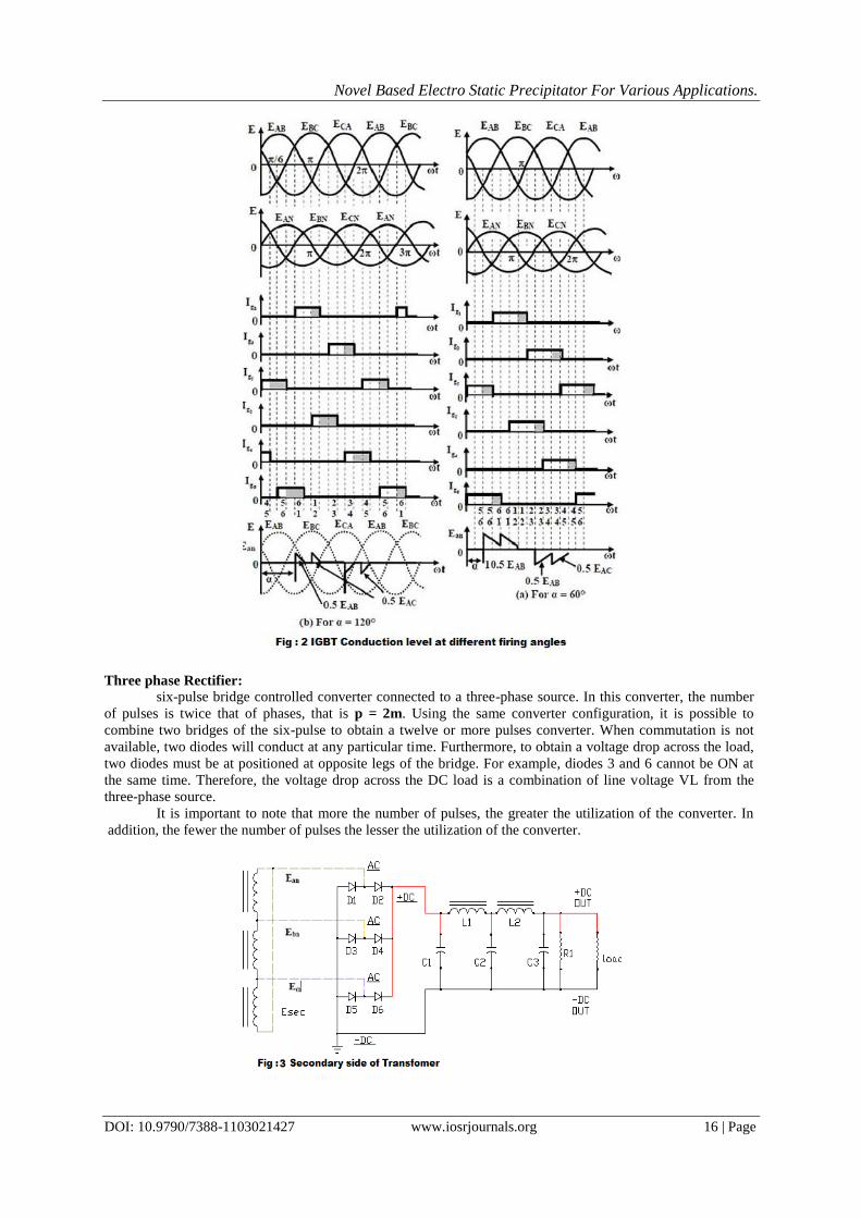
The waveforms of the input voltages, the conduction angles of I.G.B.T’S and the output voltage of one
phase, for firing delay angles (a) of (a) and (b) are shown. For 0°= a = 60° (∏/6), immediately before triggering
of IGBT 1, two IGBTS (5 & 6) conduct. Once IGBT 1 is triggered, three IGBT (1, 5 & 6) conduct. As stated
earlier, a IGBT turns off, when the current through it goes to zero. The conditions alternate between two and
three conducting IGBTS.
At any time only two IGBTS conduct for 60°.= a = 90°. Although two IGBTS conduct at any time for
90° = a = 150° , there are periods, when no IGBTS are on. For a =150°, there is no period for which two IGBTS
are on, and the output voltage becomes zero at a=150°(5∏/6). The range of delay angle is 0°=a=150°.
To derive an expression for the average output voltage of three phase full converter with high load
assuming continuous and constant load current. The output load voltage consists of 6 voltage pulses over a
period of 2∏ radians, hence the average output voltage is calculated as

Novel Based Electro Static Precipitator For Various Applications.
DOI: 10.9790/7388-1103021427 www.iosrjournals.org 15 | Page
At ωt=(∏/6 +α) , IGBT is already conducting when the IGBT is turned on by applying the gating
signal to the gate of . During the time period ωt=(∏/6 +α) to (∏/2 +α), IGBTS and conduct together and the
line to line supply voltage appears across the load.
At ωt=(∏/2 +α), the IGBT-2 is triggered and IGBT6 is reverse biased immediately and IGBT6 turns
off due to natural commutation. During the time period ωt=(∏/ +α) to (5∏/6 +α), IGBT-1 and IGBT-2
conduct together and the line to line supply voltage appears across the load.The IGBTS are numbered in the
circuit diagram corresponding to the order in which they are triggered. The trigger sequence (firing sequence) of
the IGBTS is 12, 23, 34, 45, 56, 61, 12, 23, and so on. The figure shows the waveforms of three phase input
supply voltages, output voltage, the IGBTS current through IGBT1 and IGBT4, the supply current through the
line ‘a’.
We define three line neutral voltages (3 phase voltages) as follows
VRN = Van= Vm Sin ωt
Vm = Max Phase Voltage
VYN = Vbn= Vm Sin ﴾ωt -2ᴨ/3) = Vm Sin ﴾ωt -120ᶱ)
VBN = Vcn= Vm Sin ﴾ωt +2ᴨ/3) = Vm Sin ﴾ωt -240ᶱ)
Where Vm is the peak phase voltage.
The corresponding line to line voltage are
VRY = Vab = (Van - Vbn )= √3 Vm Sin ﴾ωt +ᴨ/6)
VYB = Vbc = (Vbn – Vcn )= √3 Vm Sin ﴾ωt ─ᴨ/2)
VBR = Vca = (Vcn – Van )= √3 Vm Sin ﴾ωt +ᴨ/2)
Novel Based Electro Static Precipitator For Various Applications.
DOI: 10.9790/7388-1103021427 www.iosrjournals.org 16 | Page
Three phase Rectifier:
six-pulse bridge controlled converter connected to a three-phase source. In this converter, the number
of pulses is twice that of phases, that is p = 2m. Using the same converter configuration, it is possible to
combine two bridges of the six-pulse to obtain a twelve or more pulses converter. When commutation is not
available, two diodes will conduct at any particular time. Furthermore, to obtain a voltage drop across the load,
two diodes must be at positioned at opposite legs of the bridge. For example, diodes 3 and 6 cannot be ON at
the same time. Therefore, the voltage drop across the DC load is a combination of line voltage VL from the
three-phase source.
It is important to note that more the number of pulses, the greater the utilization of the converter. In
addition, the fewer the number of pulses the lesser the utilization of the converter.

Novel Based Electro Static Precipitator For Various Applications.
DOI: 10.9790/7388-1103021427 www.iosrjournals.org 17 | Page
conduction interval conduction diode pair
ac 1 & 6
bc 3 & 6
ba 3 & 2
ca 5 & 2
cb 5 & 4
ab 1 & 4
conduction interval conduction diode pair
Vax = 0 (Diode 1 is on)
Vcy = 0 Diode 6 is on)
Vac = Vay = +Vm (Diode 2 is off)
Vbc = Vby = +0.5 (Diode 4 is off
Vba = Vbx = -0.5 Vm (Diode 3 is on)
Vca = Vcx = - Vm (Diode 5 is off)
THREE PHASE FULL CONVERTER BY USING THYRISTOR:
Three phase full converter is a fully controlled bridge controlled rectifier using six thyristors
connected in the form of a full wave bridge configuration. All the six thyristors are controlled switches which
are turned on at a appropriate times by applying suitable gate trigger signals, more switching losses and
harmonic distortions are minimized with the help of this process when compared to the diode bridge rectifier
circuit.
The three phase full converter is extensively used in industrial power applications upto about 120kW
output power level, where two quadrant operations is required. The figure shows a three phase full converter
with highly inductive load. This circuit is also known as three phase full wave bridge or as a six pulse converter.
At ωt=(∏/6 +α) , thyristor is already conducting when the thyristor is turned on by applying the gating signal to
the gate of . During the time period ωt=(∏/6 +α) to (∏/2 +α), thyristors and conduct together and the line to
line supply voltage appears across the load.
At ωt=(∏/2 +α), the thyristor T2 is triggered and T6 is reverse biased immediately and T6 turns off due
to natural commutation. During the time period ωt=(∏/ +α) to (5∏/6 +α), thyristor T1 and T2 conduct together
and the line to line supply voltage appears across the load.
The thyristors are numbered in the circuit diagram corresponding to the order in which they are
triggered. The trigger sequence (firing sequence) of the thyristors is 12, 23, 34, 45, 56, 61, 12, 23, and so on.
The figure shows the waveforms of three phase input supply voltages, output voltage, the thyristor current
through T1 and T4, the supply current through the line ‘a’.

Novel Based Electro Static Precipitator For Various Applications.
DOI: 10.9790/7388-1103021427 www.iosrjournals.org 18 | Page
We define three line neutral voltages (3 phase voltages) as follows
VRN = Van= VmSinωt : Where Vm = Max Phase Voltage.
VYN = Vbn= VmSin(ωt ─2∏/3) = VmSin(ωt ─120)
VBN = Vcn= VmSin(ωt +2∏/3) = VmSin(ωt + 120) =VmSin(ωt ─240)
Where Vm the peak phase voltage of a star connect source corresponding lint to line voltage are
VRY = Vab =(Van-Vbn) = √3 Vm Sin((ωt + ∏/6)
VYB = Vbc =(Vbn-Vcn) = √3 Vm Sin((ωt ─ ∏/2)
VBR = Vca =(Vcn-Van) = √3 Vm Sin((ωt + ∏/2)
The output load voltage consists of 6 voltage pulses over a period of 2∏ radians, hence the average
output voltage is calculated as
VO(dc) = Vdc = 6/2ᴨ o dωt
VO = Vab = √3 Vm Sin((ωt + ∏/6)
Vdc =
√3 Vm Sin((ωt + ∏/6)
Novel Based Electro Static Precipitator For Various Applications.
DOI: 10.9790/7388-1103021427 www.iosrjournals.org 19 | Page
Vdc = 3/ᴨ √3 Vm Sin((ωt + ∏/6) dωt
Vdc = 3√3 Vm /ᴨ = 3 Vm L /ᴨ
Where Vm L = √3 Vm is line to line voltage
The maximum average dc output voltage is obtained for delay angle α = 0
Vo= [6/2ᴨ
V02d(ωt)]
1/2
Vo = [6/2ᴨ V
2ab d(ωt)]
1/2
High frequency transformer with transformer switchover:
One of the many requirements of the modern inverter is a broad, coordinated input and voltage range
with a consistently high degree of efficiency across the entire operating range of the inverter.To satisfy this
requirement, implementing a high frequency transformer (HF transformer) in most of its current inverters. This
HF transformer has a transformer switchover that ensures a consistently high degree of efficiency right across
the input voltage range.It is often incorrectly assumed that the maximum degree of efficiency at a particular
voltage is one of the factors responsible for producing a good annual yield, when it is in fact the more or less
constant degree of efficiency over the entire voltage range, maximum efficiency
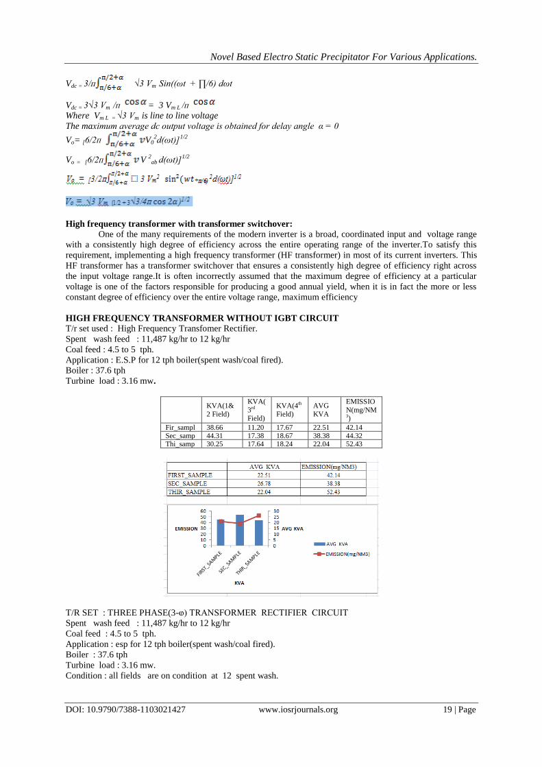
HIGH FREQUENCY TRANSFORMER WITHOUT IGBT CIRCUIT
T/r set used : High Frequency Transfomer Rectifier.
Spent wash feed : 11,487 kg/hr to 12 kg/hr
Coal feed : 4.5 to 5 tph.
Application : E.S.P for 12 tph boiler(spent wash/coal fired).
Boiler : 37.6 tph
Turbine load : 3.16 mw.
KVA(1&
2 Field)
KVA(
3rd Field)
KVA(4th
Field)
AVG
KVA
EMISSIO
N(mg/NM3)
Fir_sampl
e
38.66 11.20 17.67 22.51 42.14 Sec_samp
le
44.31 17.38 18.67 38.38 44.32 Thi_samp
le
30.25 17.64 18.24 22.04 52.43
T/R SET : THREE PHASE(3-ⱷ) TRANSFORMER RECTIFIER CIRCUIT
Spent wash feed : 11,487 kg/hr to 12 kg/hr
Coal feed : 4.5 to 5 tph.
Application : esp for 12 tph boiler(spent wash/coal fired).
Boiler : 37.6 tph
Turbine load : 3.16 mw.
Condition : all fields are on condition at 12 spent wash.

Novel Based Electro Static Precipitator For Various Applications.
DOI: 10.9790/7388-1103021427 www.iosrjournals.org 20 | Page
KVA(1
&2
Field)
KVA(3rd
Field)
KVA(4th
Field)
AVG
KVA
EMISSION(m
g/NM3)
First
Sam 7.67 16.71 18.22 14.20
6.004 20.64 18.16 14.93 AVG 14.56 34.47
Second
Sam
6.03 21.44 18.32 15.26
11.06 21.44 18.30 16.93
16.09 32.95
THREE PHASE(3-ⱷ) T.R SET READINGS WITH IGBT -CIRCUIT.
Tr-set used: Three phase transformer rectifier with IGBT power circuit.
Application : esp for 12 tph boiler(spent wash/coal fired).
Boiler load : 37.7 ,36.7,36.6 tph.
Spent wash : 12,11.8,11.4 tph.
Coal feed : 4.1 to 4.5 tph.
Kva(1&2
field)
Kva(3rd
field)
Kva(4th
field)
Avg
kva
Emission
mg/nm3
First sample 5.6 13.7 12.7 9.66 19
Second sample 6.5 14.23 12.11 10.94 17
Third sample 4.5 15.4 11.79 10.56 20
TRANSFORMER WITH IGBT POWER CIRCUIT AT PRIMARY AND THYRISTOR AT SECONDARY
SIDE.
Tr-set used : Three phase transformer with igbt ,thyristor
set readings.
Application : esp for 12 tph boiler(spent wash/coal fired).
Boiler load : 37.7 ,36.7,36.6 tph.
Spent wash : 12,11.8,11.4 tph.
Coal feed : 4.1 to 4.5 tph.
Kva(1&2 field) Kva(3rd field) Kva(4th field) Avg kva Emission mg/nm3
First sample 3.6 11.7 11.6 9 15
Second sample 4.5 10.23 10.11 8.28 14.5
Third sample 3.5 10.4 9.79 7.89 13.8

Novel Based Electro Static Precipitator For Various Applications.
DOI: 10.9790/7388-1103021427 www.iosrjournals.org 21 | Page
HIGH FREQUENCY TRANSFORMER CONDITION
Application : esp for 12 tph boiler(spent wash/coal fired).
Spent wash : 11,600 kg/hr to 12.1 kg/hr
Coal feed : 4.2 to 4.6 tph.
Boiler : 37.7 tph Turbine load : 3.18 mw.
APPLICATION E.S.P FOR 1 ᵡ 40 TPH BOILER( SPENT WASH/COAL FIRED)
FUEL USED SPENT WASH + INDIAN/IMPORTED COAL
SPECIFICATION NO ( ALL FIELDS ARE ON CONDITION 12 TPH)
S.NO PARAMETER UNIT DESIGNED MEASURED
1 No of
mechanical / Electrical fields
No. 4 MECH
4 ELECTRICAL
4 MECH/4 ELECTRICAL
2 Gas Flow At
Inlet (Total)
AM3/HR 147600 150295
A Gas Flow Per Pass
AM3/SEC 41 27.483
B Gas Flow At
Outlet
AM3/HR 95000 98940.48
3 Gas Temp At Inlet (Operating)
DEG C 200 200
3a Gas Temp At
Outlet
DEG C 175 175
4 Moisture % v/v 16.06 14.85
5 Inlet dust load GMS/NM3 77.63 77.63
6 Emission
guarantee
MGMS/NM3 100 134
7 Collection
efficiency
% 99.87 99.98
8 Plate area (total) M2 4320 4320
A Plate area (per
pass)
M2 4320 4320
9 SCA M2/M3/SEC 105.37 130.37
10 Velocity M/SEC 0.57 13.29
11 Migration
velocity (wd)
CM/SEC 5.51 7.418
Treatment time SEC 21.1 8.126
12 Suction pressure at esp
Inlet
(-)MMWC ±400 mmWC ±400 mmWC
13 Pressure drop across
The esp(top
entry)
MM OF WC 25-30 9.2
14 Esp penhouse temp
ıC 90-110 100
15 Boiler capacity TPH 40 36.6
16 Oxygen % 6.45 6.15
THREE PHASE TRANSFORMER CONDITION
Application : Esp for 12 tph boiler(spent wash/coal fired). Spent wash : 11.8 kg/hr to 12 kg/hr
Boiler load : 36.7 ,37,37-tph.

Novel Based Electro Static Precipitator For Various Applications.
DOI: 10.9790/7388-1103021427 www.iosrjournals.org 22 | Page
Spent wash : 12,11.5,11.8. Coal feed : 4.1 to 4.5 tph.
Condition : all fields are on condition
APPLICATION E.S.P FOR 1 ᵡ 40 TPH BOILER( SPENT WASH/COAL FIRED)
FUEL USED SPENT WASH + INDIAN/IMPORTED COAL
S.NO PARAMETER UNIT DESIGNED MEASURED
1 No of mechanical /
Electrical fields No.
4 MECH
4 ELECTRICAL 4 MECH/4 ELECTRICAL
2 Gas Flow At Inlet (Total) AM3/HR 147600 150295
A Gas Flow Per Pass AM3/SEC 41 27.483
B Gas Flow At Outlet AM3/HR 95000 98945.48
3 Gas Temp At Inlet (Operating) DEG C 200 200
3a Gas Temp At Outlet DEG C 175 175
4 Moisture % v/v 16.06 14.85
5 Inlet dust load GMS/NM3 77.63 77.63
6 Emission guarantee MGMS/NM3 100 17.33
7 Collection efficiency % 99.87 99.99
8 Plate area (total) M2 4320 4320
A Plate area (per pass) M2 4320 4320
9 SCA M2/M3/SEC 105.37 130.37
10 Velocity M/SEC 0.57 13.29
11 Migration velocity (wd) CM/SEC 5.51 7.418
Treatment time SEC 21.1 8.126
12 Suction pressure at esp
Inlet (-)MMWC ±400 mmWC ±400 mmWC
14 Esp penhouse temp ıC 90-110 100
15 Boiler capacity TPH 40 36.6
16 Oxygen % 6.45 6.15
THREE PHASE TRANSFORMER WITH POWER CIRCUIT IGBT CONNECTED TO PRIMARY OF TRANSFORMER
Application : Esp for 12 tph boiler(spent wash/coal fired).
Spent wash : 11.8 kg/hr to 12 kg/hr
Boiler load : 36.7 ,37,37-tph. Spent wash : 12,11.5,11.8.
Coal feed : 4.1 to 4.5 tph.
APPLICATION E.S.P FOR 1 ᵡ 40 TPH BOILER( SPENT WASH/COAL FIRED)
FUEL USED
SPENT WASH + INDIAN/IMPORTED COAL
S.NO PARAMETER UNIT DESIGNED MEASURED
1 No of mechanical /
Electrical fields No.
4 MECH
4 ELECTRICAL 4 MECH/4 ELECTRICAL
2 Gas Flow At Inlet (Total) AM3/HR 147600 150295
A Gas Flow Per Pass AM3/SEC 41 27.483
B Gas Flow At Outlet AM3/HR 95000 98945.48
3 Gas Temp At Inlet
(Operating) DEG C 200 200
3a Gas Temp At Outlet DEG C 175 175
4 Moisture % v/v 16.06 14.85
5 Inlet dust load GMS/NM3 77.63 77.63
6 Emission guarantee MGMS/NM3 100 16.3
7 Collection efficiency % 99.87 99.997
8 Plate area (total) M2 4320 4320
A Plate area (per pass) M2 4320 4320
9 SCA M2/M3/SEC 105.37 130.37
10 Velocity M/SEC 0.57 13.29
11 Migration velocity (wd) CM/SEC 5.51 7.418
Treatment time SEC 21.1 8.126
12 Suction pressure at esp Inlet
(-)MMWC ±400 mmWC ±400 mmWC
13 Pressure drop across
The esp(top entry) MM OF WC 25-30 9.2
14 Esp penhouse temp ıC 90-110 100
15 Boiler capacity TPH 40 36.6
16 Oxygen % 6.45 6.15
THREE PHASE TRANSFORMER WITH IGBT AT PRIMARY AND THYRISTOR SECONDARY OF TRANSFORMER
Application : Esp for 12 tph boiler(spent wash/coal fired).
Spent wash : 11.8 kg/hr to 12 kg/hr

Novel Based Electro Static Precipitator For Various Applications.
DOI: 10.9790/7388-1103021427 www.iosrjournals.org 23 | Page
Boiler load : 36.7 ,37,37-tph. Spent wash : 12,11.5,11.8.
Coal feed : 4.1 to 4.5 tph.
APPLICATION E.S.P FOR 1 ᵡ 40 TPH BOILER( SPENT WASH/COAL FIRED)
FUEL USED
SPENT WASH + INDIAN/IMPORTED COAL
S.NO PARAMETER UNIT DESIGNED MEASURED
1 No of mechanical /
Electrical fields No.
4 MECH
4 ELECTRICAL 4 MECH/4 ELECTRICAL
2 Gas Flow At Inlet (Total) AM3/HR 147600 150295
A Gas Flow Per Pass AM3/SEC 41 27.483
B Gas Flow At Outlet AM3/HR 95000 98945.48
3 Gas Temp At Inlet
(Operating) DEG C 200 200
3a Gas Temp At Outlet DEG C 175 175
4 Moisture % v/v 16.06 14.85
5 Inlet dust load GMS/NM3 77.63 77.63
6 Emission guarantee MGMS/NM3 100 15.1
7 Collection efficiency % 99.87 99.998
8 Plate area (total) M2 4320 4320
A Plate area (per pass) M2 4320 4320
9 SCA M2/M3/SEC 105.37 130.37
10 Velocity M/SEC 0.57 13.29
11 Migration velocity (wd) CM/SEC 5.51 7.418
Treatment time SEC 21.1 8.126
12 Suction pressure at esp Inlet
(-)MMWC ±400 mmWC ±400 mmWC
14 Esp penhouse temp ıC 90-110 100
15 Boiler capacity TPH 40 36.6
16 Oxygen % 6.45 6.15

Novel Based Electro Static Precipitator For Various Applications.
DOI: 10.9790/7388-1103021427 www.iosrjournals.org 24 | Page

Novel Based Electro Static Precipitator For Various Applications.
DOI: 10.9790/7388-1103021427 www.iosrjournals.org 25 | Page

Novel Based Electro Static Precipitator For Various Applications.
DOI: 10.9790/7388-1103021427 www.iosrjournals.org 26 | Page

Novel Based Electro Static Precipitator For Various Applications.
DOI: 10.9790/7388-1103021427 www.iosrjournals.org 27 | Page