novel control strategy for multi-level active power filter without
TRANSCRIPT
Energy and Power Engineering, 2010, 2, 262-270 doi:10.4236/epe.2010.24038 Published Online November 2010 (http://www.SciRP.org/journal/epe)
Copyright © 2010 SciRes. EPE
Novel Control Strategy for Multi-Level Active Power Filter without Phase-Locked-Loop
Guojun Tan, Xuanqin Wu, Hao Li, Meng Liu School of Information and Electrical Engineering, China University of Mining and Technology, Xuzhou, China
E-mail: [email protected],[email protected] Received June 13, 2010; revised August 9, 2010; accepted September 21, 2010
Abstract Active power filter (APF) using novel virtual line-flux-linkage oriented control strategy can not only realizes no phase-locked-loop (PLL) control, but also achieves a good inhibitory effect to interfere. However, there are some problems in the conventional method, such as the error of amplitude, the shift of phase angle and the non-determinacy of initial oriented angle. In this paper, two one-order low-pass filters are adopted in-stead of the pure integrator in the virtual line-flux-linkage observer, which can steady the phase and ampli-tude. Furthermore, an original scheme of harmonics detection under the rotating coordinate is advanced based on the simplified space vector pulse width modulation (SVPWM) strategy. Meanwhile, by using the new SVPWM algorithm, the voltage space vector diagram of the three-level inverter can be simplified and applied into that of two-level inverter, and this makes the control for Neutral Point potential easier. Keywords: Active Power Filter, Harmonics Detection, Virtual Line-Flux-Linkage Observer, Active Power
Filter Control without Phase-Locked-Loop, Space Vector Pulse Width Modulation
1. Introduction The use of nonlinear loads such as power electronic de-vices leads to serious harmonics pollution and lager voltage fluctuation. Moreover, lager unbalance voltage and current distortions in the power system are harmful to the electrical equipment and power systems. Shunt active power filter (SAPF) can well compensate the har-monic whose frequency and amplitude both changes, and it is also recognized as an effective way to manage the grid harmonic, to reactive power pollution and to im-prove the quality of the power. Active power filter (APF) is a new power electronics device for dynamic harmonics restriction and reactive compensation without influenced by system inductance [1,2], besides it has such functions: adaptive ability for the parametric variation of system and load, automatic tracing and compensation for the varying harmonics [3,4]. There are some remarkable advantages in nature of three-level APF, such as lower distortion of output waveform, lower endure voltage and less switch loss, high efficiency and low electromagnetic interference (EMI), so it helps to raise the installed ca-pacity and improves the harmonics compensation effect as well as system reliability.
On the one hand, the traditional harmonic current de-tection which is based on instantaneous reactive power adopts phase-lock-loop (PLL) to acquire the voltage vector angle [5-7], when the grid voltage fluctuation is more serious, PLL will be in unlocked condition because of the larger frequency offsets which can not accurately track the phase position. To solve the problem, this paper uses the virtual line-flux-linkage orientation to observe the vector angle, which converts the observation of vec-tor angle to the flux. By using the voltage integral on the AC side of the active filter to estimate the grid flux, PLL can be omitted; meanwhile, the power grid interference can be inhibited well. On the other hand, the traditional harmonic current detection requires that the integrated vector combined by the sine and cosine function should be synchronous and phase coincidence to the integrated vector of the three-phase positive sequence fundamental voltage, otherwise, the detection accuracy of the funda-mental positive sequence reactive component will be affected by phase difference [8]. Therefore, the harmonic detection principle based on the rotating coordinates is proposed in this paper. The application of virtual flux in active filter system also includes controlling generation of compensation current, so it has a very good control to harmonic current detection and compensation current ge-
G. J. TAN ET AL. 263 neration, and the voltage space vector modulation strat-egy SVPWM (Space Vector Pulse Width Modulation) can be easily applied to active filter control.
In this paper, the simplified three-level SVPWM with neutral point potential adaptive control is applied to con-trol multi-level active filter, based on this, a novel multi- level voltage active filter phase reconstruction algorithm is proposed. 2. Mathematical Model for Three-Level APF
and the Rotating Coordinate Based Harmonics Detection Diagram
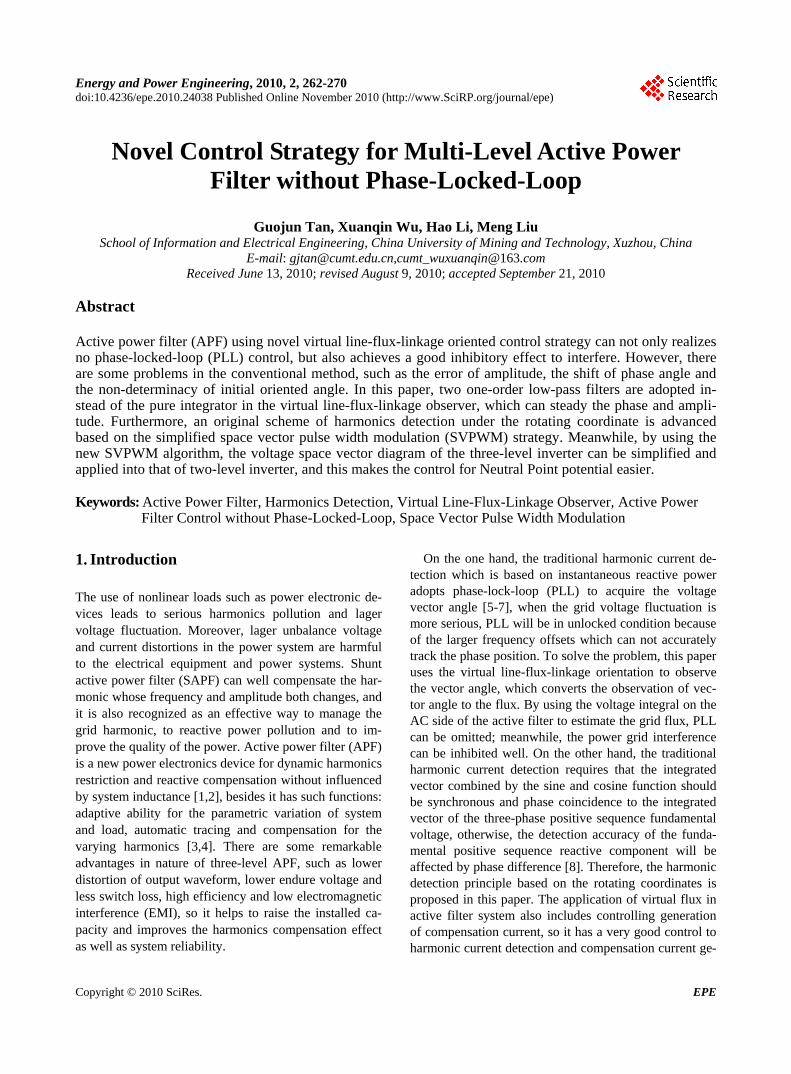
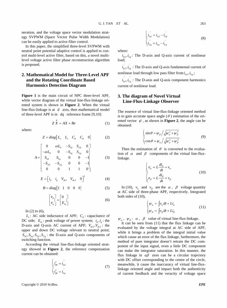
Figure 1 is the main circuit of NPC three-level APF, while vector diagram of the virtual line-flux-linkage ori-ented system is shown in Figure 2. When the virtual line-flux-linkage is at axis, then mathematical model of three-level APF is in reference frame [9,10]:
ddq
Z X AX Be (1)
where:
0s s d dZ diag L L C C (2)
1 2
1 2
1 1
2 2
0 0
0 0
0 0 1
0 0 1
0 0 1 1 0
S d d
S q q
d q
d q
L S S
L S S
A S S
S S
(3)
1 2 0T
d q dc dcX i i V V (4)
1 1 0 0 0B diag (5)
0d
q m
e
e E
(6)
In (2) to (6),
sL
S S
: AC side inductance of APF; d : capacitance of DC side; m : peak voltage of power system; : the D-axis and Q-axis AC current of APF; 1 2dc dcV V : the upper and down DC voltage relevant to neutral point;
1 1 2 2d q d q : the D-axis and Q-axis components of switching function.
CE
,S
,d qi i,
, , S
According the virtual line-flux-linkage oriented strat-egy showed in Figure 2, the reference compensation current can be obtained:
~*
~*
dh Ld
qh Lq
i i
i i
(7)
~
~
Ld Ld Ld
Lq Lq Lq
i i i
i i i
(8)
where: ,Ld Lqi i : The D-axis and Q-axis current of nonlinear
load;
,Ld Lqi i
: The D-axis and Q-axis fundamental current of
nonlinear load through low pass filter from ,Ld Lqi i ; ~ ~
,Ld Lqi i : The D-axis and Q-axis component harmonics
current of nonlinear load. 3. The diagram of Novel Virtual
Line-Flux-Linkage Observer The essence of virtual line-flux-linkage oriented method is to gain accurate space angle ( ) estimation of the ori-ented vector , as shown in Figure 2, the angle can be obtained:
2 2
2 2
sin
cos
(9)
Then the estimation of is converted to the evalua-tion of and components of the virtual line-flux- linkage.
die L v
dtdi
e L vdt
(10)
In (10), v and v are the , voltage quantity at AC side of three-phase APF, respectively. Integrated both sides of (10),
v dt Li
v dt Li
(11)
, : , value of virtual line-flux-linkage. It can be seen from (11) that the flux linkage can be
evaluated by the voltage integral at AC side of APF, while it brings a problem of the integral initial value which cause an error of the flux linkage, furthermore, the method of pure integrator doesn’t retrain the DC com-ponent of the input signal, even a little DC component can make the integrator saturation. In this manner, the flux linkage in axes can be a circular trajectory with DC offset corresponding to the centre of the circle, meanwhile, it cause the inaccuracy of virtual line-flux- linkage oriented angle and impact both the authenticity of current feedback and the veracity of voltage space
Copyright © 2010 SciRes. EPE
G. J. TAN ET AL.
Copyright © 2010 SciRes. EPE
264
Figure 1. Topology of a diode NPC three-level shunt APF.
1
s
d
q
ei
e
i
E
V
I
IL
qi
di
Ldi
Lqi
Figure 2. Vector diagram of the virtual line-flux-linkage oriented system.
nd even aggravate the performance of PF seriously. As a result, it brings large current shock
blems of pure integrator, it usually
ter (use the first order inertia fil ) instead of the f
pure integrator (
vector supply, aAin the process of starting, and even can’t start. Therefore, in order to achieve an accurate flux estimate, it’s neces-sary to make some measures to eliminate influence of the integral initial value.
In the traditional virtual flux estimation, in order to solve initial value pro
1) in flux estimation. It can be seen
sfrom the formula of the first order that the first or- filter der inertia is similar to the pure integrator when the fre-quency of the inusoidal input is far greater than s f .
Howev r, it is also required that the first order i a e nertishould have a certain decay to the direct flow, that means
f should be a certain value, and not too small, other-wise the ecay will be very slow .So the first order low dpa
mea
ss filter has contradictions between approximating pure points and decaying of the DC component, that
ns f must maintain a certain value to decay, while it also should be far less than to approximate the integral. Know from the above analysis.
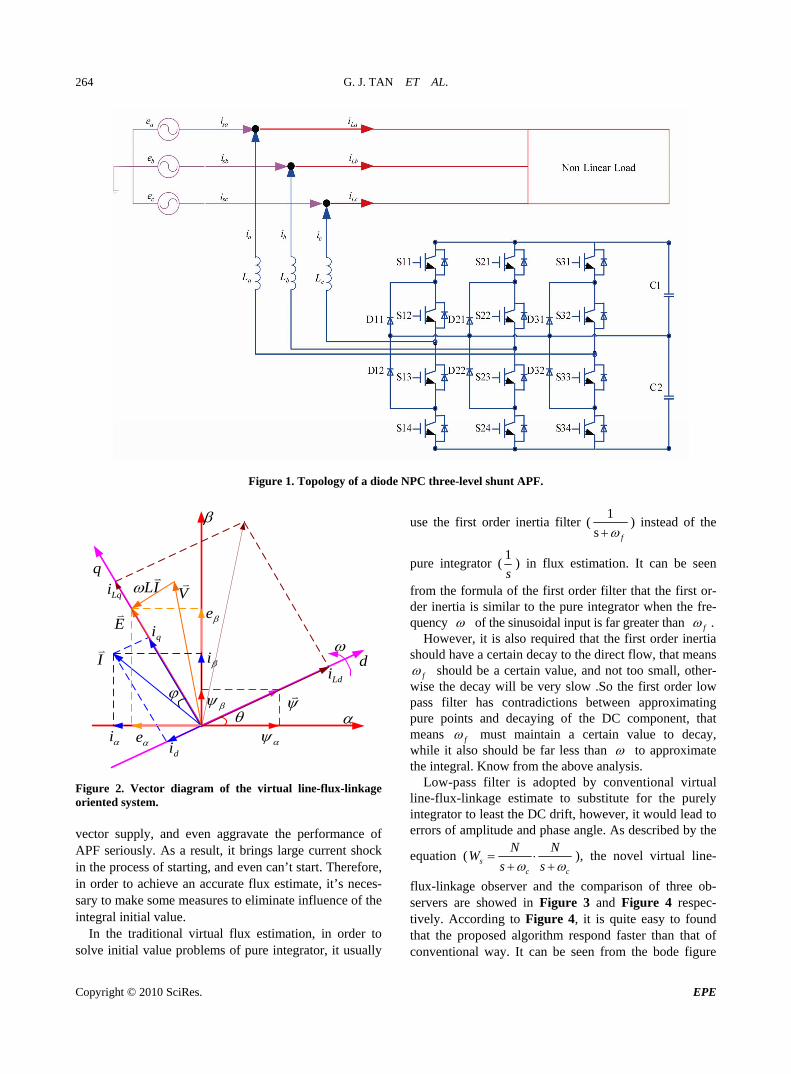
Low-pass filter is adopted by conventional virtual line-flu nkage estimate to substitute for the purely integrator to least the DC drift, howev , it would lead to errors of amplitude and phase angle. As desc
x-lier
ribed by the
equation ( sc c
N NW
s s
), the novel virtual line-
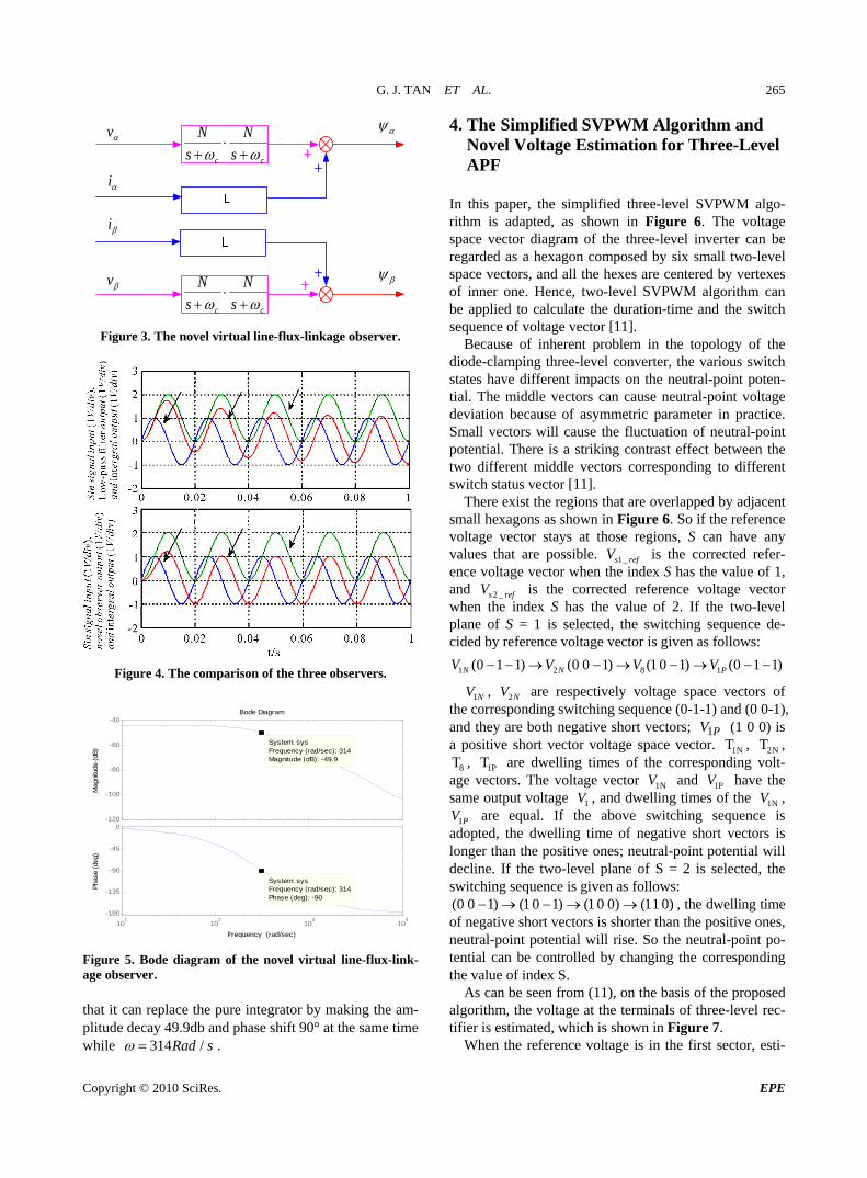
flux-linkage observer and the comparison of three ob-servers are showed in Figure 3 and Figure 4 respec-tively. Acc , it is quite easy to found ording to Figure 4that the proposed algorithm respond faster than that of
conventional way. It can be seen from the bode figure
G. J. TAN ET AL. 265
v
i
v
i
cc s
N
s
N
cc s
N
s
N
Figure 3. The novel virtual line-flux-linkage observer.
Figure 4. The comparison of the three observers.
Bode Diagram
Frequency (rad/sec)
101
102
103
104
-180
-135
-90
-45
0
System: sysFrequency (rad/sec): 314Phase (deg): -90
Pha
se (
deg)
-120
-100
-80
-60
-40
System: sysFrequency (rad/sec): 314Magnitude (dB): -49.9
Mag
nitu
de (
dB)
Figure 5. Bode diagram of the novel virtual line-flux-link-age observer. that it can replace the pure integrator by making the am-plitude decay 49.9db and phase shift 90° at the same time while 314 /Rad s .
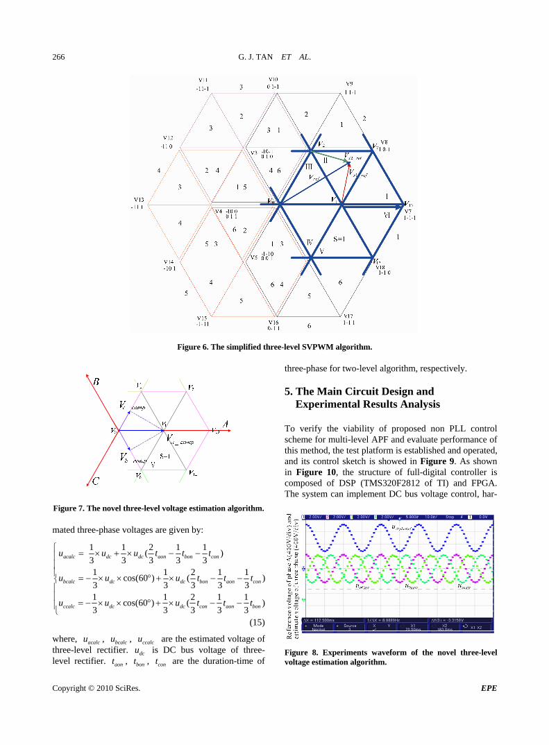
4. The Simplified SVPWM Algorithm and
ritsp tor diagram of the three-level inverter can be
garded as a hexagon composed by six small two-level
se neutral-point voltage de
Novel Voltage Estimation for Three-Level APF
In this paper, the simplified three-level SVPWM algo-
hm is adapted, as shown in Figure 6. The voltage ace vec
respace vectors, and all the hexes are centered by vertexes of inner one. Hence, two-level SVPWM algorithm can be applied to calculate the duration-time and the switch sequence of voltage vector [11].
Because of inherent problem in the topology of the diode-clamping three-level converter, the various switch states have different impacts on the neutral-point poten-tial. The middle vectors can cau
viation because of asymmetric parameter in practice. Small vectors will cause the fluctuation of neutral-point potential. There is a striking contrast effect between the two different middle vectors corresponding to different switch status vector [11].
There exist the regions that are overlapped by adjacent small hexagons as shown in Figure 6. So if the reference voltage vector stays at those regions, S can have any values that are possible. 1_s refV is the corrected refer-ence voltage vector when the index S has the value of 1, and 2 _s refV is the corrected reference voltage vector when the index S has the value of 2. If the two-level plane of S = 1 is selected switching sequence de-cided by reference voltage vector is given as follows:
1 2 8 1(0 ) (0 0 1) (1 0 1) (0 1 1)N N PV V V V
, the
1 1
1NV , 2NV are respectively voltage space vectors of the corresponding switching sequence (0-1-1) and (0 0-1),
both negative short vectors; (1 0 0) isvoltage space
and they a
8 , T
re a positive short vector
are
PV1 vector.
es o
1N 2N
1P dwelling times of the corresponding volt-age vectors. The voltage vector 1NV and 1PV have the same output voltage 1V , and dwelling tim f the 1NV ,
1
T , T , T
PV are equal. If the above switching se ncp the dwelling time of negative short vectors is
longer than the positive ones; neutral-point potential will decline. If the two-level plane of S = 2 is selected, the
ching sequence is given as follows: (0 0 1) (1 0 1) (1 0 0) (11 0)
que e is ad
s
o te
wit
d,
, the dwelling time of negative short vectors is shorter than the positive ones, neutral-point potential will rise. So the neutral-point po-tential can be controlled by changing th
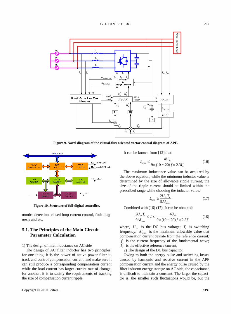
As can be seen from (11), on the basis of the proposed algorithm, the voltage at the terminals of three-level rec-
e corresponding the value of index S.
tifier is estimated, which is shown in Figure 7. When the reference voltage is in the first sector, esti-
Copyright © 2010 SciRes. EPE
G. J. TAN ET AL.
Copyright © 2010 SciRes. EPE
266
Figure 6. The simplified three-level SVPWM algorithm.
Figure 7. The novel three-level voltage estimation algorithm. mated three-phase voltages are given by:
1 1 2 1 1( )acalc dc dc aon bon conu u u t t t
3 3 3 3 3
1 1)
3 3 3 3 31 1 2 1 1
cos(60 ) ( )3 3 3 3 3
aon con
ccalc dc dc con aon bon
t t
u u u t t t
(15)
where, are the estimated voltage of DC bus voltage of three-
are the duration-time of
three-phase for two-level algorithm, respectively.
Design and Experimental Results Analysis
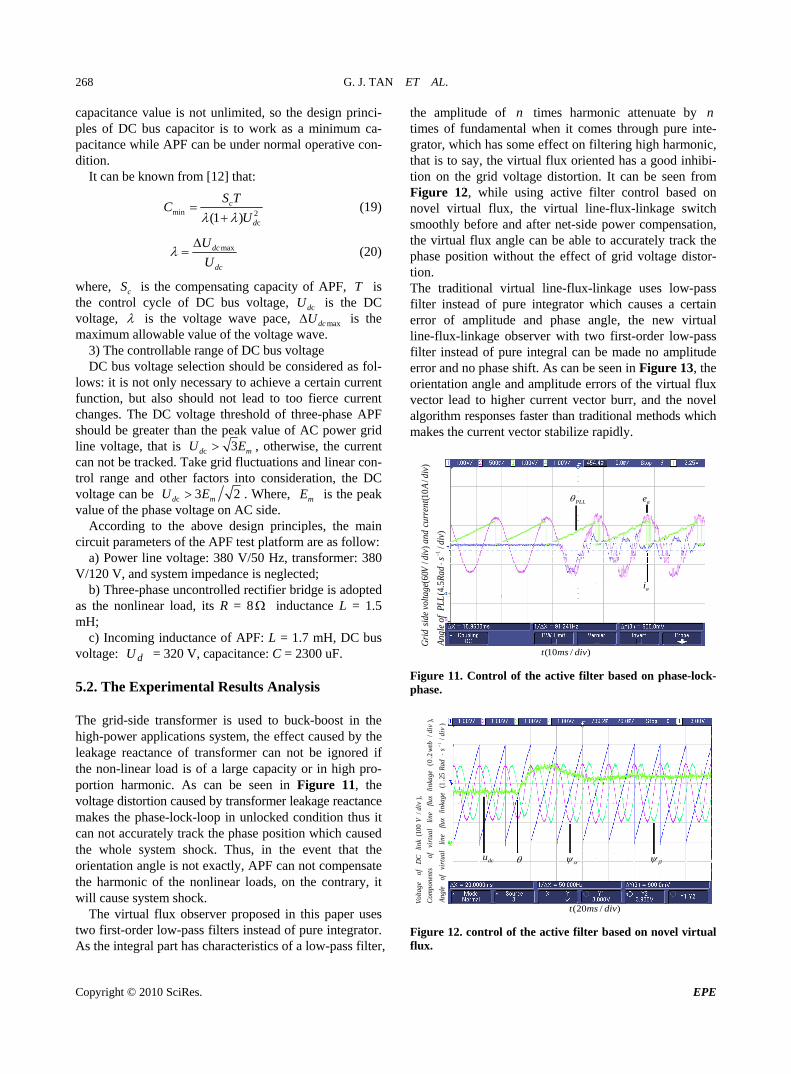
To verify the viability of proposed non PLL control scheme for multi-level APF and evaluate performance of this method, the test platform is established and operated, and its control sketch is showed in Figure 9. As shown in Figure 10, the structure of full-digital controller is composed of DSP (TMS320F2812 of TI) and FPGA. The system can implement DC bus voltage contro
5. The Main Circuit
l, har-
1 1 2cos(60 ) (bcalc dc dc bonu u u t
acalcu , three-level rectifier. level rectifier.
bcalcu ,
aont ,
ccalcu
dcu is
bont , tcon
Figure 8. Experiments waveform of the novel three-level voltage estimation algorithm.
G. J. TAN ET AL. 267
*qi
*dhi
di
qi
*dcu
ai bi
dcu*du *
qu
*u *
u
as bs cs
sincos
sincos
*qhi
Lai Lbi
IPARK PARK
aL
bL
cL
Load
Linear N
on
LdiLqi
HPF
AlphaCalcu
BetaCalcu
Figure 9. Novel diagram of the virtual-flux oriented vector control diagram of APF.
Figure 10. Structure of full-digital controller. monics detection, closeosis and etc.
5.1. The Principles of the Main Circuit Parameter Calculation
1) The design of inlet inductance on AC side
The design of AC filter inductor has two principles: for one thing, it is the power of active power filter to track and control compensation current, and make sure it can still produce a corresponding compensation current while the load current has larger current rate of change; for another, it is to satisfy the requirements of trackinthe size of compensation current ripple.
It can be known from [12] that:
d-loop current control, fault diag- n
g
cmax *
4
9 (10 ~ 20) 2.3d
a
UL
f I
(16)
The maximum inductance value can be acquired by the above equation, while the minimum inductor value is determined by the size of allowable ripple current, the size of the ripple current should be limited within the prescribed range while choosing the inductor value.
minmax
2
9dc sU T
Li
(17)
Combined with (16) (17), It can be obtained:
c
9 9 (10 ~ 20)d s dcLi f
*
max
2 4
2.3 a
U T U
I (18)
where, cdU is the DC bus voltage; sT is swicy; maxi
tching equenfr is the maximum allowable value that
compensation current deviate from the reference current; f is the current frequency of the fundamental wave; *aI is the effective reference current.
osses cause current in the APF
mpensation current and the energy pulse caused by the apacitance
is difficult to maintain a constant. The larger the capaci-tor is, the smaller such fluctuations would be, but the
2) The design of the DC bus capacitor Owing to both the energy pulse and switching l
d by harmonic and reactive cofilter inductor energy storage on AC side, the c
Copyright © 2010 SciRes. EPE
G. J. TAN ET AL. 268
capacitance value is not unlimited, so the design princi-ples of DC bus capacitor is to work as a minimum ca-pacitance while APF can be under normal operative con-dition.
It can be known from [12] that:
min 2cS T
C (19) c(1 ) dU
maxdc
dc
U
U
w
(20)
here, cS is the compensating capacity of APF, T is the control cycle of DC bus voltage, cdU is the DC voltage, is the voltage wave pace, maxdcU is the maximum allowable value of the voltage wave.
3) The controllable range of DC bus voltage DC bus voltage selection should be considered as fol-
lows: it is not only necessary to function, but also should not lead to too fierce current ch ase APF should be greater than the peak value of AC power grid line voltage, that is
achieve a certain current
anges. The DC voltage threshold of three-ph
c 3d mU E , otherwise,can not be tracked. Take grid fluctuations and linear con-
e a erbe
the current
trol rang nd other factors into consid ation, the DC voltage can c 3 2d mE . Where, mE is the peak value of the phase voltage on AC side.
According to the above design principles, the main cuit parameters of the APF test platf
U
cir orm are as follow: ansformer: 380
V
d-side transformer is used to buck-boost in the hi e effect caused by the leakage reactance of transformer can the non-linear load is of a large caportion harmonic. As can be seen in Figure 11, the voltage distortion caused by tramakes the phase-lock-loop in
use
notn
ual flux orie
ux, the virtual -liner compensation,
th
tio low-pass
filn
ux-linkage observer with two first-order low-pass fil
no 3, the rientation angle and amplitude errors of the virtual flux
the novel gorithm responses faster than traditional methods which
a) Power line voltage: 380 V/50 Hz, tr/120 V, and system impedance is neglected; b) Three-phase uncontrolled rectifier bridge is adopted
as the nonlinear load, its R = 8 inductance L = 1.5 mH;
c) Incoming inductance of APF: L = 1.7 mH, DC bus voltage: dU = 320 V, capacitance: C = 2300 uF. 5.2. The Experimental Results Analysis The gri
gh-power applications system, thnot be ignored if
pacity or in high pro-
nsformer leakage reactance unlocked condition thus it
can not accurately track the phase position which ca d the whole system shock. Thus, in the event that the orientation angle is not exactly, APF can compensate the harmonic of the nonlinear loads, on the co trary, it will cause system shock.
The virtual flux observer proposed in this paper uses two first-order low-pass filters instead of pure integrator. As the integral part has characteristics of a low-pass filter,
the amplitude of n times harmonic attenuate by n times of fundamental when it comes through pure inte-grator, which has some effect on filtering high harmonic, that is to say, the virt nted has a good inhibi-tion on the grid voltage distortion. It can be seen from Figure 12, while using active filter control based on novel virtual fl line-flux kage switch smoothly before and after net-side pow
e virtual flux angle can be able to accurately track the phase position without the effect of grid voltage distor-
n. The traditional virtual line-flux-linkage uses
ter instead of pure integrator which causes a certain error of amplitude and phase a gle, the new virtual line-fl
ter instead of pure integral can be made no amplitude error and phase shift. As can be seen in Figure 1ovector lead to higher current vector burr, andalmakes the current vector stabilize rapidly.
ai
aePLL
)/
5.4(
)/
10()
/60(
1di
vs
Rad
PLL
div
Acu
rren
tan
ddi
vV
volta
geid
e
of
Ang
le
Gri
d
)/10( divmst
Figure 11. Control of the active filter based on phase-lock- phase.
s
dcu
)/
25.1(
),/
2.0(
),/
100
(
1di
vs
Rad
linka
geflu
xne
div
web
linka
geflu
xlin
ert
ual
div
Vk
livi
rtua
lof
Ang
le
viof
Com
pone
nts
linD
Cof
Volta
ge
)/20( divmst
Figure 12. control of the active filter based on novel virtual flux.
Copyright © 2010 SciRes. EPE
G. J. TAN ET AL. 269
(a)
(b)
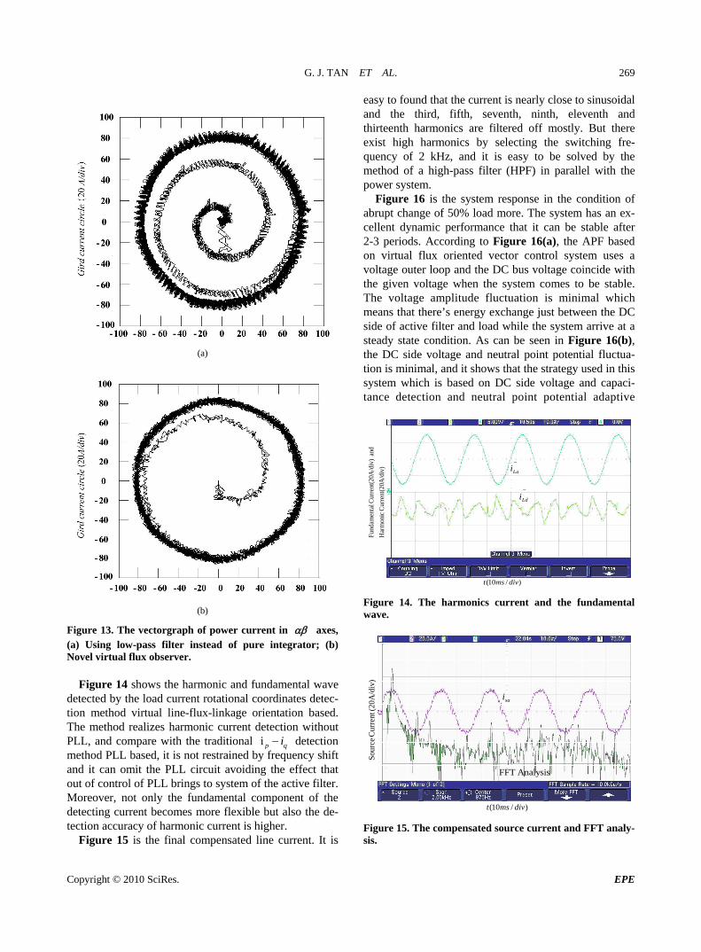
Figure 13. The vectorgraph of power current in axes, (a) Using low-pass filter instead of pure integrator; (b) Novel virtual flux observer.
Figure 14 shows the harmonic and fundamental wave detected by the load current rotational coordinates detec-tion method virtual line-flux-linkage orientation based. The method realizes harmonic current detection without PLL, and compare with the traditional i p qi
by freque detection
method PLL based, it is not restrained ncy shift and it can omit the PLL circuit avoiding the effect that out of control of PLL brings to system of the active filter. Moreover, not only the fundamental component of the detecting current becomes more flexible but also the de-tection accuracy of harmonic current is higher.
Figure 15 is the final compensated line current. It is
easy to found that the curre nearly close to sinusoidal nd the third, fifth, seventh, ninth, eleventh and
thirteenth harmonics are filtered off mostly. But there exist high harmonics by selecting the switching fre-quency of 2 kHz, and it is easy to be solved by the method of a high-pass filter (HPF) in parallel with the power system.
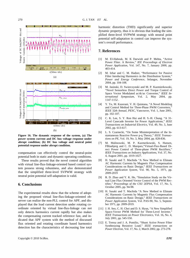
Figure 16 is the system response in the condition of abrupt change of 50% load more. The system has an ex-cellent dynamic performance that it can be stable after 2-3 periods. According to Figure 16(a), the APF based on virtual flux oriented vector control system uses a voltage outer loop and the DC bus voltage coincide with the given voltage when the system comes to be stable. The voltage amplitude fluctuation is minimal which means that there’s energy exchange just between the DC side of active filter and load while the system arrive at a steady state condition. As can be seen in Figure 16(b)the DC side voltage and n oint potential fluctua-
nt isa
, eutral p
tion is minimal, and it shows that the strategy used in this system which is based on DC side voltage and capaci-tance detection and neutral point potential adaptive
Lai
~
Ldi
A
/div
)C
urre
nt(2
0
Har
mon
ic
and
A
/div
)C
urre
nt(2
0 l
Fund
amen
ta
)/10( divmst
Figure 14. The harmonics current and the fundamental wave.
sai
Analysis FFT
(20
Cur
rent
Sour
ce
)/10( divmst
Figure 15. The compensated source current and FFT analy-sis.
A/d
iv)
Copyright © 2010 SciRes. EPE
G. J. TAN ET AL.
Copyright © 2010 SciRes. EPE
270
dcu
/div
)
an
sai
(10A
C
urre
nts
So
urce
d
div)
200V
/lin
DC
of
Vol
tage
s
)/50( divmst (a)
k(
updcu _
downdcu _
intneutral_pou
(50/
div
int
di
v)0V
/
)po
neut
ral
of
Vol
tage
s
an
dli
DC
of
Vol
tage
s
)/50( divmst (b)
Figure 16. The dynamic response of the system, (a) The power system current and DC bus voltage response under abrupt condition; (b) DC bus voltage and neutral point potential response under abrupt condition.
hese results proved that the novel control algorithm with virtual line-flux-linkage-oriented based control sys-tem possess strong robustness, and also demonstrated that the simplified three-level SVPWM strategy with neutral point potential self-adaptation is valid. 6. Conclusions The experimental results show that the scheme of adopt-ing the proposed virtual line-flux-linkage-oriented ob-server can realize the non-PLL control for APF, and dis-played that the load current detection under rotatinordinate oriented by virtual line-flux-linkage can nonly detects harmonics cu t rapidly but also makes
e compensating current tracked reference fast, and in-dicated that APF system with the method of discusseflux oriented and rotating coordinate based harmonicsdetection has the characteristics of decreasing line total
harmonic distortion (THD) significantly and superior dynamic property, thus it is obvious that leading the sim-plified three-level SVPWM strategy with neutral point potential self-adaptation in control can improve the sys-tem’s overall performance. 7. References [1] M. EI-Habouk, M. K Darwish and P. Mehta, “Active
Power Fliter. A Review,” IEE Proceedings of Electron Power Application, Vol. 147, No. 7, January 2000, pp. 403-414.
[2] M. Izhar and C. M. H r, “Performance for Passive
rque Control of
ng. “A 31- s,” IEEE
Industrial Electrics, Vol. 49, No. 3, June
] L. S. Czarnecki, “On Some Misinterpretation of the In-
da “A New Method to Elimate urrents by Magnetic Flux Compensation
on Basic Design,” IEEE Transactions on , Vol. PAS-90, No. 5, Septem-
adzeFilter Inreducing Harmonics in the Distribution System,” Power and Energy Conference, Selangor, November 2004, pp. 104-108.
[3] M. Jasinski, D. Swierczynski and M. P. Kazmierkowski, “Novel Sensorless Direct Power and ToSpace Vector Modulated ac/dc/ac Converter,” IEEE In-ternational Symposium, Vol. 2, May 2004, pp. 1147-1152 .
nk(1
0
[4] Y. Ye, M. Kazerani, V. H. Quintana, “A Novel Modeling and Control Method for Three-Phase PWM Converters,” IEEE 32th Annual, PESC, Vancouver, Vol. 1, June 2001, pp. 102-107.
[5] C. K. Lee, S. Y. Ron Hui and H. S.-H. ChuLevel Casecade Inverter for Power ApplicationTransactions on2002, pp. 613-617.
[6stantaneous Reactive Power p-q Theory,” IEEE Transac-tions on PE, Vol. 19, No. 3, May 2004, pp. 828-836.
[7] M. Malinowski, M. P. Kazmerkowski, S. Hansen, FBlaabjerg and C. D. Marques,“Virtual-Flux-Based Di-rect Power Control of Three-phase PWM Rectifiers,” IEEE Transactions on Industry Applications, Vol. 37, No. 4, August 2001, pp. 1019-1027.
[8] H. Sasaki and T. Machida “A New Method to Elimate AC Harmonic Currents by Magnetic Flux Compensation Considerations on Basic Design,” IEEE Transactions on Power Application System, Vol. 90, No. 5, 1971, pp. 2009-2019
[9] R. D. Zhao and Y. K. He, “Simulation Study on the Vir-tual Line Flux Oriented Vector Control of the PWM Rec-tifier,” Proceedings of the CSU 2EPSA, Vol. 17, No. 5, October 2005, pp. 94-98.
10] H. Sasaki and T. Machi
compensation can effectively control the neutral-poinpotential both in static and dynamic operating conditions.
T
t
[
g co-o
ber 1971, pp. 2009-2019.
[11] J. H. Seo, C. H. Choi and D. S. Hyun, “A New Simplified Space-Vector PWM Method for Three-Level Inverter,” IEEE Transactions on Power Electronics, Vol. 16, No. 4,
AC Harmonic CConsiderationsPower Application System
t rren
thd
July 2001, pp. 545-550.
[12] E. Teresa and J. A. Pomilio, “Shunt Active Power Filter Synthesizing Resistive Load,” IEEE transactions on Power Electron, Vol. 17, No. 2, March 2002, pp. 273-278.