novel electrochemical test bench for evaluating the...
TRANSCRIPT
Novel Electrochemical Test Bench for Evaluating the FunctionalFatigue Life of Biomedical Alloys
M.F. IJAZ,1,3 S. DUBINSKIY,1 Y. ZHUKOVA,1 A. KOROBKOVA,1
Y. PUSTOV,1 V. BRAILOVSKI,2 and S. PROKOSHKIN1,4
1.—National University of Science and Technology ‘‘MISIS’’, 4 Leninskiy prosp., Moscow, RussianFederation 119049. 2.—Ecole de Technologie Superieure, 1100, rue Notre Dame Ouest, MontrealH3C 1K3, Canada. 3.—e-mail: [email protected]. 4.—e-mail: [email protected]
The aim of the present work was first to develop and validate a test bench thatsimulates the in vitro conditions to which the biomedical implants will beactually subjected in vivo. For the preliminary application assessments, thestrain-controlled fatigue tests of biomedically pure Ti and Ti–Nb–Zr alloy insimulated body fluid were undertaken. The in situ open-circuit potentialmeasurements from the test bench demonstrated a strong dependence on thedynamic cycling and kind of material under testing. The results showed thatduring fatigue cycling, the passive oxide film formed on the surface of Ti–Nb–Zr alloy was more resistant to fatigue degradation when compared with pureTi. The Ti–Nb–Zr alloy exhibited prolonged fatigue life when compared withpure Ti. The fractographic features of both materials were also characterizedusing scanning electron microscopy. The electrochemical results and thefractographic evidence confirmed that the prolonged functional fatigue life ofthe Ti–Nb–Zr alloy is apparently ascribable to the reversible martensiticphase transformation.
INTRODUCTION
Among the metallic biomedical materials, thepure Ti, Ti–6Al–4V, and Ti–Ni alloys have beeninvestigated extensively for their diverse applica-tions in the orthopedic and dental fields. Neverthe-less, for the long-term survival of indwellingimplants, the hypersensitivity of nickel and toxicityof vanadium has become an issue of widespreadconcern.1 On the other hand, although pure Ti (alsoknown as CP Ti) has excellent biocompatibility, itsapplications are limited because of its poor mechan-ical properties.1,2 Therefore, to circumvent thesechallenging problems, rigorous endeavors have beenundertaken to explore the new generation of Ni- andV-free biomedical alloys.2–6 In this context, supere-lastic beta titanium alloys seems conducive tofuture implant applications.2–11
Nevertheless, during service, the implants arecommonly subjected to cyclic fatigue under thecorrosive physiological conditions of the humanbody.2,5,12 In fact, the destructive nature of thecorrosion-assisted fatigue cracking and overallfatigue degradation can incapacitate the long-term
performance of implants.12–15 Therefore, it is vitalto investigate the functional fatigue life underphysiological conditions. Despite all its practicalrelevance, the specific pseudo-physiological testbench for evaluating the functional fatigue life ofthe superelastic beta titanium alloys and corre-sponding in situ electrochemical results revealingthe impact of cycling on the corrosive and passivebehavior for this kind of alloys are sparse in theliterature and hence require more research.
Our current strategy is motivated by our previousworks, which were done to investigate the corrosionfatigue properties under the applied strain valueonly limited to 0.8%.11,13,16 Nonetheless, from theviewpoint of practical applications, it is essential tomonitor the functional fatigue performance of newbiomedical alloys at higher strain amplitudeconditions.11
In this context, one objective of this work is todesign a novel multifunctional physiological testbench for evaluating the functional fatigue charac-teristics under dynamic mechanical cycling. Subse-quently, the preliminary experimental results onthe corrosive and passive behavior of recently
JOM, Vol. 69, No. 8, 2017
DOI: 10.1007/s11837-017-2375-x� 2017 The Minerals, Metals & Materials Society
1334 (Published online May 18, 2017)
developed Ti–22Nb–6Zr alloy3,5,11 were investigatedand discussed in comparison with the commer-cially available implant materials, i.e., pure Ti(Grade-2).1,2
EXPERIMENTAL
Alloy Synthesis and Specimen Preparation
The Ti–22Nb–6Zr (at.%) alloy (hereinafterreferred to as Ti–Nb–Zr) was synthesized by thevacuum arc-melting method. After the meltingprocedure, the 80-mm-diameter ingot was hotforged at 1173 K and machined to a 50 mm diam-eter after quenching. Next, the ingot was subjectedto a series of thermomechanical treatments thatincluded multipass hot-rolling, rotational-forging,and cold-drawing operations with intermediateannealing treatments until the accumulated truestrain approached e = 0.3 in the final passes.11 Thefinal diameter of the cold drawn wire specimen is0.5 mm. Subsequently, the cold-drawn wire speci-men was subjected to post-deformation annealing(PDA) at 873 K for 1.8 ks followed by quenching inwater. Accordingly, the commercially available a-type pure Ti (hereinafter referred as Ti) was alsoheat treated at 973 K for 1.8 ks mainly to establishthe recrystallized state. Eventually, to remove theslightly oxidized surface, all the heat-treated spec-imens were mechanically abraded by fine siliconcarbide abrasive paper.
Alloy Characterization Method
To have an insight into microstructural morphol-ogy, transmission electron microscopy (TEM) obser-vations were performed on the disk-shaped Ti–Nb–Zr alloy thin foils with a standard grid size of3.05 mm. A JEM-2100 (JEOL Ltd./Japan) TEMoperating at 200-kV accelerating voltage, with acamera length of 25 cm was used. Specimens forTEM analysis were prepared from the sheet with aconsistent thermomechanical treatments.11
Electrochemical Behavior Testing
During the fatigue test, the electrochemical inves-tigations were based on conventional open-circuitpotential (OCP) measurements that were performedusing IPC Pro MF potentiostat (Volta Co, Russia) at298 K. The electrolyte used for the electrochemicalanalysis was 0.9% NaCl physiological solution(Braun, Germany).
Fractography of the Specimen After FatigueTesting
The fracture surfaces after the dynamic fatiguefracture were investigated using a Vegas-Tescanscanning electron microscope (SEM) at an accelerat-ing voltage of 20 kV and a working distance of 15 mm.
Design and Manufacturing of Test Bench forthe Electrochemical Examinations DuringFatigue Test
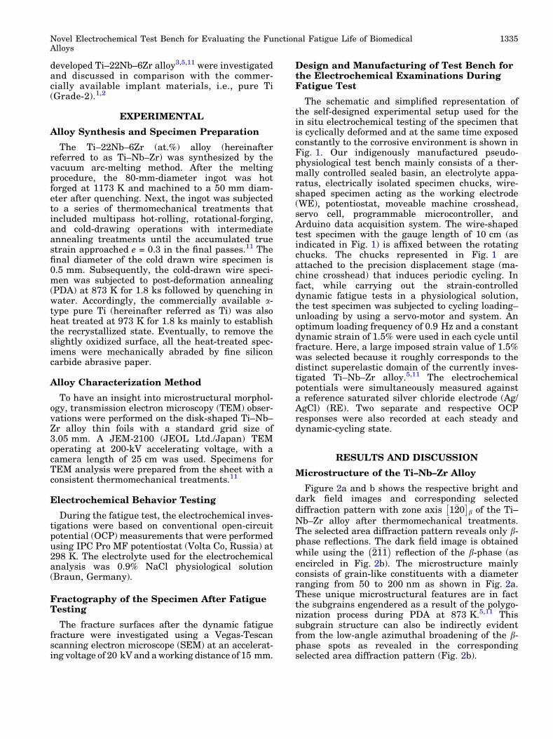
The schematic and simplified representation ofthe self-designed experimental setup used for thein situ electrochemical testing of the specimen thatis cyclically deformed and at the same time exposedconstantly to the corrosive environment is shown inFig. 1. Our indigenously manufactured pseudo-physiological test bench mainly consists of a ther-mally controlled sealed basin, an electrolyte appa-ratus, electrically isolated specimen chucks, wire-shaped specimen acting as the working electrode(WE), potentiostat, moveable machine crosshead,servo cell, programmable microcontroller, andArduino data acquisition system. The wire-shapedtest specimen with the gauge length of 10 cm (asindicated in Fig. 1) is affixed between the rotatingchucks. The chucks represented in Fig. 1 areattached to the precision displacement stage (ma-chine crosshead) that induces periodic cycling. Infact, while carrying out the strain-controlleddynamic fatigue tests in a physiological solution,the test specimen was subjected to cycling loading–unloading by using a servo-motor and system. Anoptimum loading frequency of 0.9 Hz and a constantdynamic strain of 1.5% were used in each cycle untilfracture. Here, a large imposed strain value of 1.5%was selected because it roughly corresponds to thedistinct superelastic domain of the currently inves-tigated Ti–Nb–Zr alloy.5,11 The electrochemicalpotentials were simultaneously measured againsta reference saturated silver chloride electrode (Ag/AgCl) (RE). Two separate and respective OCPresponses were also recorded at each steady anddynamic-cycling state.
RESULTS AND DISCUSSION
Microstructure of the Ti–Nb–Zr Alloy
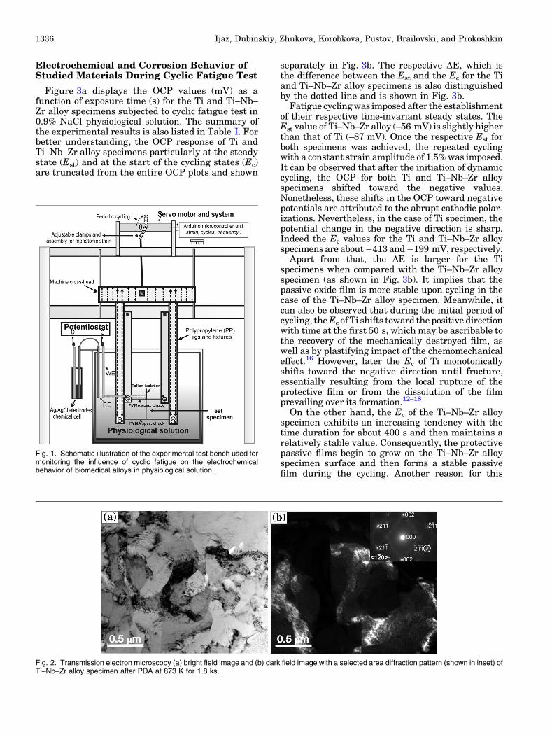
Figure 2a and b shows the respective bright anddark field images and corresponding selecteddiffraction pattern with zone axis 1�20
� �b of the Ti–
Nb–Zr alloy after thermomechanical treatments.The selected area diffraction pattern reveals only b-phase reflections. The dark field image is obtainedwhile using the �2�1�1
� �reflection of the b-phase (as
encircled in Fig. 2b). The microstructure mainlyconsists of grain-like constituents with a diameterranging from 50 to 200 nm as shown in Fig. 2a.These unique microstructural features are in factthe subgrains engendered as a result of the polygo-nization process during PDA at 873 K.5,11 Thissubgrain structure can also be indirectly evidentfrom the low-angle azimuthal broadening of the b-phase spots as revealed in the correspondingselected area diffraction pattern (Fig. 2b).
Novel Electrochemical Test Bench for Evaluating the Functional Fatigue Life of BiomedicalAlloys
1335
Electrochemical and Corrosion Behavior ofStudied Materials During Cyclic Fatigue Test
Figure 3a displays the OCP values (mV) as afunction of exposure time (s) for the Ti and Ti–Nb–Zr alloy specimens subjected to cyclic fatigue test in0.9% NaCl physiological solution. The summary ofthe experimental results is also listed in Table I. Forbetter understanding, the OCP response of Ti andTi–Nb–Zr alloy specimens particularly at the steadystate (Est) and at the start of the cycling states (Ec)are truncated from the entire OCP plots and shown
separately in Fig. 3b. The respective DE, which isthe difference between the Est and the Ec for the Tiand Ti–Nb–Zr alloy specimens is also distinguishedby the dotted line and is shown in Fig. 3b.
Fatigue cycling was imposed after the establishmentof their respective time-invariant steady states. TheEst value of Ti–Nb–Zr alloy (–56 mV) is slightly higherthan that of Ti (–87 mV). Once the respective Est forboth specimens was achieved, the repeated cyclingwith a constant strain amplitude of 1.5% was imposed.It can be observed that after the initiation of dynamiccycling, the OCP for both Ti and Ti–Nb–Zr alloyspecimens shifted toward the negative values.Nonetheless, these shifts in the OCP toward negativepotentials are attributed to the abrupt cathodic polar-izations. Nevertheless, in the case of Ti specimen, thepotential change in the negative direction is sharp.Indeed the Ec values for the Ti and Ti–Nb–Zr alloyspecimens are about�413 and�199 mV, respectively.
Apart from that, the DE is larger for the Tispecimens when compared with the Ti–Nb–Zr alloyspecimen (as shown in Fig. 3b). It implies that thepassive oxide film is more stable upon cycling in thecase of the Ti–Nb–Zr alloy specimen. Meanwhile, itcan also be observed that during the initial period ofcycling, theEc of Ti shifts toward the positive directionwith time at the first 50 s, which may be ascribable tothe recovery of the mechanically destroyed film, aswell as by plastifying impact of the chemomechanicaleffect.16 However, later the Ec of Ti monotonicallyshifts toward the negative direction until fracture,essentially resulting from the local rupture of theprotective film or from the dissolution of the filmprevailing over its formation.12–18
On the other hand, the Ec of the Ti–Nb–Zr alloyspecimen exhibits an increasing tendency with thetime duration for about 400 s and then maintains arelatively stable value. Consequently, the protectivepassive films begin to grow on the Ti–Nb–Zr alloyspecimen surface and then forms a stable passivefilm during the cycling. Another reason for this
Fig. 1. Schematic illustration of the experimental test bench used formonitoring the influence of cyclic fatigue on the electrochemicalbehavior of biomedical alloys in physiological solution.
Fig. 2. Transmission electron microscopy (a) bright field image and (b) dark field image with a selected area diffraction pattern (shown in inset) ofTi–Nb–Zr alloy specimen after PDA at 873 K for 1.8 ks.
Ijaz, Dubinskiy, Zhukova, Korobkova, Pustov, Brailovski, and Prokoshkin1336

stable passive film may be because of the‘‘mechanochemical effect,’’ which is elicited at thespecimen–electrolyte interface.13,16
Nevertheless, when the dynamic fracture stage forboth specimens was approached (as pointed in Fig. 3a),a slight but distinct negative shift in the OCP valuescorresponding to fracture was observed that wasfollowed by a rapid shift in the positive directionimplying the passivation of the freshly formed sur-face.12,13,16 FromOCP plots, the dynamic fracturestagefor the Ti and Ti–Nb–Zr alloy specimens are preciselyestimated to occur around the exposure time of 846 s(Ec = –451 mV) for Ti and 1536 s (Ec = –147 mV) forTi–Nb–Zr alloy, respectively. Based on these results, itcan be concluded that the Ti–Nb–Zr alloy possesses abetter corrosion resistance under dynamic cycling as aresult of the higher stability ofprotective oxidefilmthatis also evident from the steady OCP variations of Ti–Nb–Zr alloy when compared with Ti.
Finally, while comparing the corresponding fatiguelife (a total number of fatigue cycles Nf) of Ti and Ti–Nb–Zr alloy specimens, the Nf values for Ti and Ti–Nb–Zr alloy specimens in the physiological solutionare calculated to be 750 and 1516 cycles, respectively.
Fractographic Analysis of the DynamicallyFractured Specimens
To discuss the pronounced fatigue lifetime of Ti–Nb–Zr alloy in the physiological solution, theapparent surface components of the fracture
surfaces of Ti and Ti–Nb–Zr alloy specimens weresystematically compared. Figure 4a–d shows thegeneral fractography of Ti and Ti–Nb–Zr alloyspecimens, which were characterized by SEM. Thesequential elaboration of the macroscopic andmicroscopic regions for Ti and Ti–Nb–Zr alloyspecimens, particularly the crack origin, fatiguecrack propagation region, and final unstable regionthat is near the edge, is also illustrated in Fig. 4aand c, respectively. On the other hand, for the sakeof clarity, an example showing the segment offatigue striations by the crack propagation in thestable region and dimples at the unstable region arealso highlighted with the white rectangular boxesand shown in Fig. 4b and d, respectively. Fromgeneral aspects, it is evident that the dynamicfracture in both specimens was elicited mainly by atransgranular pattern12,14–16 as the correspondingthree regions (as shown in Fig. 4a–d) are easilyidentifiable.
In particular, from Fig. 4a and b, it is alsonoteworthy that in the case of the Ti specimen,the stable region showing the fatigue crack propa-gation is much smaller than the final overloadedregion. In fact, the enlarged unstable zone of Ti (asshown in Fig. 4a and b) on the one hand corrobo-rates the pronounced shift of the Ec value towardthe negative potentials (as shown in Fig. 3a and b).Nonetheless, during the fatigue testing of the Tispecimen, the subsequent rapture of the localpassive film caused by the influence of cycling has
Fig. 3. (a) Comparison of the OCP curves acquired during the cyclic fatigue testing of the Ti and Ti–Nb–Zr alloy specimens while imposing aconstant strain amplitude of 1.5% and (b) OCP curves zoomed around the evolution of the steady (Est) and cyclic (Ec) response under dynamic(cyclic) fatigue testing of the Ti and Ti–Nb–Zr alloy specimens.
Table I. Comparison of the experimental results from fatigue testing of the selected biomedical materials inthe pseudo-physiological test bench
Materials Number of fatigue cycles to dynamic fracture (Nf)
E (mV) (Ag/AgCl)
Est Ec DE Est�Ecð Þ
Pure Ti 750 �87 �413 �326Ti–Nb–Zr alloy 1516 �56 �199 �143
Novel Electrochemical Test Bench for Evaluating the Functional Fatigue Life of BiomedicalAlloys
1337

accelerated the corrosion-assisted fatigue crackgrowth in the localized unstable zone, which hasultimately led to the dynamic fatigue fracture andrelatively shorter fatigue life.
Surprisingly, the fractography of the Ti–Nb–Zralloy specimen (as shown in Fig. 4c and d) clearlydemonstrates a much larger fatigue striation regionwhen compared with the Ti specimen (as shown inFig. 4a and b). It is previously reported that in aphysiological solution, the stress-induced marten-sitic transformation during loading/unloadingcycles can prevent the spreading of the crack andenhance the plastic properties of surface layers.13,16
Finally, by correlating the microstructural resultswith the OCP response, it is summarized that theincrease in the fatigue life of Ti–Nb–Zr alloy is firstrelated to the stable passive film formation thatinhibits the local corrosive attack and second to thereversible stress-induced martensitic transforma-tion5,13,14,16 that can accommodate the materialstrains during subsequent unloading cycle andeventually preclude the dynamic fatigue fracturefor a longer period of time.
CONCLUSION
In conclusion, for the successful applications ofthe recently developed biomedical alloys in thepotential indwelling implant applications, it isimportant to evaluate their functional fatigue per-formance in physiological conditions. In this con-text, a novel pseudo-physiological test bench wasspecifically designed and manufactured. Next, thetest bench was validated while using recentlydeveloped superelastic Ti–Nb–Zr alloy and pureTi. Experimental results have revealed that underdynamic cycling, the Ti–Nb–Zr alloy specimen
exhibits higher cyclic state open-circuit potentialvalues (Ec) and its passive oxide film is morestable when compared with pure Ti specimen. TheTi–Nb–Zr alloy manifests a much longer functionalfatigue life as well. Fractographical characteristicsafter fatigue fracture showed that the compara-tively longer fatigue life of Ti–Nb–Zr alloy could becorrelated with the appearance of a large fatiguestriations region that has engendered from thereversible stress-induced martensitic transforma-tion. Based on these conclusions, which have beenreproduced from our test bench, it is suggested thatfor advanced biomedical applications, the Ti–Nb–Zralloy is less susceptible to fatigue degradation whencompared with pure Ti.
ACKNOWLEDGEMENTS
The authors acknowledge Dr. Andrey Korotitskiyfor his valuable participation in the test bench de-sign. The present work was carried out with thefinancial support of the Ministry of Education andScience of the Russian Federation, in the frameworkof the Increase Competitiveness Program of NUST‘‘MISIS’’ (Grant R4-2016-56), and of the NaturalScience and Engineering Research Council of Ca-nada (NSERC), the Fonds de Recherche Nature etTechnology du Quebec (FQR-NT).
REFERENCES
1. C.N. Elias, J.H.C. Lima, R. Valiev, and M.A. Meyers, JOM60, 46 (2008).
2. M. Niinomi, Y. Liu, M. Nakai, and H. Liu, Regen. Biomater.3, 173 (2016).
3. T. Yoneyama and S. Miyazaki, Shape Memory Alloys forBiomedical Applications (Cambridge: Woodhead Publish-ing, 2009).
4. H.Y. Kim and S. Miyazaki, Shape Mem. Superelasticity 2,380 (2016).
5. S. Prokoshkin, V. Brailovski, S. Dubinsky, Y. Zhukova, V.Sheremetyev, A. Konopatsky, and K. Inaekyan, ShapeMem. Superelasticity 2, 130 (2016).
6. P. Castany, A. Ramarolahy, F. Prima, P. Laheurte, C.Curfs, and T. Gloriant, Acta Mater. 88, 102 (2015).
7. M.F. Ijaz, H.Y. Kim, H. Hosoda, and S. Miyazaki, ScriptaMater. 72–73, 29 (2014).
8. P. Xue, Y. Li, F. Zhang, and C. Zhou, Scripta Mater. 101, 99(2015).
9. M.F. Ijaz, H.Y. Kim, H. Hosoda, and S. Miyazaki, Mater.Sci. Eng., C 48, 11 (2015).
10. M.F. Ijaz, D. Laille, L. Heraud, D.M. Gordin, P. Castany,and T. Gloriant, Mater. Lett. 177, 39 (2016).
11. S.M. Dubinskiy, S.D. Prokoshkin, V. Brailovski, K.E. In-aekyan, A.V. Korotitskiy, M.R. Filonov, and M.I. Petrzhik,Phys. Met. Metallogr. 112, 503 (2011).
12. ASTM F 1801–1997, Standard Practice for Corrosion Fa-tigue Testing of Metallic Implant Material (2004).
13. Y.S. Zhukova, Y.A. Pustov, A.S. Konopatsky, S.M. Dubin-skiy, M.R. Filonov, and V. Brailovski, Mater. Today Proc.2S, S991 (2015).
14. Y.L. Zhou, M. Niinomi, and T. Akahori, Mater. Trans. 45,1549 (2004).
15. L.C. Campanelli, C.C. Bortlan, P.S. Carvalho da Silva, C.Bolfarini, and N.T.C. Oliveira, J. Mech. Behav. Biomed. 65,542 (2017).
Fig. 4. SEM micrographs show the comparison of the overall frac-ture surfaces of (a, b) Ti and (c, d) Ti–Nb–Zr alloy specimens aftercyclic fatigue testing in physiological solution.
Ijaz, Dubinskiy, Zhukova, Korobkova, Pustov, Brailovski, and Prokoshkin1338
16. Y.A. Pustov, Y.S. Zhukova, and M.R. Filonov, Prot. Met.Phys. Chem. Surf. 50, 524 (2014).
17. L. Qiang, L. Junjie, M. Guanghao, L. Xuyan, and P. Deng,Mater. Des. 111, 421 (2016).
18. R. Ion, S.I. Drob, M.F. Ijaz, C. Vasilescu, P. Osiceanu, D.M.Gordin, A. Cimpean, and T. Gloriant, Materials 9, 818(2016).
Novel Electrochemical Test Bench for Evaluating the Functional Fatigue Life of BiomedicalAlloys
1339