novel pm tool steel with improved hardness and toughness...
TRANSCRIPT

Doctoral School in Materials, Mechatronics
and Systems Engineering
Novel PM Tool Steel with improved hardness and toughness
Faraz Deirmina
September 2017
XX
IX c
yc
le
NOVEL PM TOOL STEEL WITH IMPROVED
HARDNESS AND TOUGHNESS
Faraz Deirmina
E-mail: [email protected]
Approved by:
Prof. Massimo Pellizzari -, Advisor Department of Industrial Engineering University of Trento, Italy.
Ph.D. Commission:
Prof. Alberto Molinari, Department of Industrial Engineering University of Trento, Italy. Prof. Maurizio Vedani, Department of Mechanical Engineering Politecnico di Milano, Italy. Prof. Elena Gordo ODÉRIZ, Department of Materials Science and Engineering and Chemical Engineering University of Carlos III de Madrid, Spain.
University of Trento, Department of Industrial Engineering
September 2017

III
University of Trento - Department of - - - - - - - - - Doctoral Thesis
Name - 2017 Published in Trento (Italy) – by University of Trento
ISBN: - - - - - - - - -

IV
To my wife, my comrade Camellia,
and her adorable children
Oblomov, Truffaut and Hugo

V
Abstract
Ultrafine grained (~ 1μm) steels have been the subject of extensive research work during the past years. These steels generally offer interesting perspectives looking for improved mechanical properties. UFG Powder Metallurgy hot work tool steels (HWTS) can be fabricated by high energy mechanical milling (MM) followed by spark plasma sintering (SPS). However, similarly to most UFG and Nano-Crystalline (NC) metals, reduced ductility and toughness result from the early plastic instabilities in these steels. Industrialization of UFG PM Tool Steels requires the application of specific metallurgical tailoring to produce tools with sound mechanical properties or in a more optimistic way, to break the Strength-Toughness “trade-off” in these materials. Among the possible ways proposed to restore ductility and toughness without losing the high strength, “Harmonic microstructure” design seems to be a very promising endeavor in this regard. Harmonic microstructure materials consist of a tunable volume fraction of evenly spaced “isolated” coarse-grained particles (CG) surrounded by a 3D interconnected network of UFG particles. CGs provide ductility and toughness, while high strength is guaranteed by the interconnected network of UFGs. This peculiar design offers an extra work hardening due to the generation of geometrically necessary dislocations at the interfaces of UFGs and confined CGs that are essentially present to accommodate the strain gradient imposed by the inhomogeneous (bimodal grained) microstructure.
The first part of this work is devoted to the development of PM tool steels with harmonic microstructure. Due to the difficulties of processing hard tool steel particles according to the methods reported in the literature, an economical, simple alternative approach is also proposed. Near full density “Harmonic structure“ AISI H13 samples were produced using different volume fractions of UFG/NC mechanically milled (MM) and CG as-atomized particles followed by short time (30 min) low-temperature (1100°C) SPS. A combination of high hardness and significantly improved fracture toughness was achieved for the blends containing more that 50% UFG particles. The optimized mechanical properties was achieved by the mixture of 60% UFG particles where the sample showed a hardness near to the value predicted by the rule of mixtures (i.e. 405 HV10 vs. 406 HV10) while apparent fracture toughness (Kapp) was about 10% higher than that of predicted by the same rule (i.e. 52.0 MPa*m1/2 vs. ~47.0 MPa*m1/2). A toughening effect was evidenced for the samples essentially showing harmonic microstructure. Toughening was interpreted to be the result of the deviatory effect of coarse-grained round atomized particles together with energy

VI
dissipation by decohesion at the CG/UFG or UFG/UFG interfaces leading to a local drop of the driving force for the crack propagation. The design allowed to easily adjust the strength and toughness to meet the specific application-oriented requirements. The harmonic steel was also subjected to Thermal Fatigue (TF) testing. The preliminary results confirmed that this microstructure combined the beneficial effects of both of its constituents, i.e., the low crack nucleation rate of CG H13 and the low crack propagation rate of UFG H13, thus showing the lowest pyrocracking factor. Moreover, TF crack deflection as an extrinsic toughening mechanism was evidenced in Harmonic Microstructure.
The second part of this work deals with the production and characterization of a PM HWTS reinforced with partially stabilized zirconia (PSZ). HWTS composites show improved hardness and remarkable wear resistance but generally also a systematic lower fracture toughness than the base material. Deteriorated toughness in metal matrix composites (MMCs) with a high strength matrix is mainly interpreted as a result of early damage initiation at the hard particles (HPs) or Matrix-HP interface. This damage can be even anticipated in the presence of readily damaged HPs (i.e. processing related flaws). Selection of PSZ as reinforcement was aimed at improving the strength and fracture toughness of the composite by taking advantage of the transformation toughening effect of PSZ. Two different types of PSZ, different volume fractions (10 and 20 vol. %) and sizes of reinforcement were used. Mechanical Alloying (MA) was used to process the composite powders to refine the matrix microstructure and both the matrix and PSZ particle size hence increasing the strength of the PSZ particles according to the Griffith strength formalism, and also to overcome the aggregation problems. Powders were consolidated by (SPS). The influence of processing parameters on density and microstructure was investigated. Short time (30 min) low-temperature (1100°C) consolidation by SPS allowed preserving the refined microstructure while achieving a maximum relative density of 98.6%. Moreover, short time sintering did not allow the extensive formation of thermodynamically plausible reaction products at the PSZ-H13 interface. As a result of dispersion hardening, the hardness of the as-sintered composites (i.e. maximum hardness of ~ 920 HV10) was increased compared to the mechanically milled UFG H13 (i.e. ~ 755 HV10), while in comparison to the as-atomized H13 (i.e. ~ 640 HV10) the improved hardness was ascribed to the synergic effect of dispersion hardening, microstructural refinement and strain hardening induced by MA. In these composites, tempering resistance at 550°C and 650°C was significantly improved due to the dispersion hardening effect. The hot compressive yield strength of the composites at 650°C and 450°C was increased up to 1.8 times the unreinforced UFG H13. t to m transformation during hot compression was evidenced and contributed to the strengthening. The hardness of the composites in heat treated condition (i.e. ~ 600 HV10) was significantly improved compared to that of the unreinforced matrix (i.e. ~ 420 HV10) while the apparent fracture toughness was drastically decreased to half the Kapp of the base material (19 MPa*m1/2 vs. 36 MPa*m1/2). However, the fracture toughness was slightly higher than that of a TiC reinforced H13 (i.e. 17 MPa*m1/2) with the same hardness (i.e. ~ 600 HV10).

VII

VIII
Table of contents
Chapter I ...................................................................................... 1
Introduction ................................................................................ 1
1.1 Strength and Toughness, two mutually exclusive
properties .................................................................................... 1 1.1.1 Grain boundary strengthening ................................ 1 1.1.2 Strengthening from fine hard particles ................. 2 1.1.3 Strain hardening ......................................................... 3 1.1.4 Martensite Strengthening ......................................... 4
1.2 Effect of strengthening on fracture toughness and
ductility ........................................................................................ 5 1.2.1 Effect of grain refinement on fracture toughness
................................................................................................... 5 1.2.2 Effect of grain refinement on ductility................... 7
1.3 Powder Metallurgy tool steels ........................................ 9 1.3.1 Microstructural refinement of powders and
processing of composite powders ................................ 10 1.3.2 Mechanical Milling and Mechanical Alloying .... 10 1.3.3 Consolidation techniques ...................................... 12
1.3.3.1 HIP Consolidation ......................................... 12 1.3.3.2 Spark Plasma Sintering ................................... 14
1.4 AISI H13 Tool Steel .......................................................... 16 1.4.1 Research progress in production of UFG PM
AISI H13 ................................................................................. 17
1.5 Particle reinforced Hot Work Tool Steels ................... 18 1.5.1 Role of HPs in Densification of MMCs ................ 19 1.5.2 Role of HPs in Mechanical performance of the
steel matrix composites .................................................... 20 1.5.2.1 HPs size and volume fraction ........................ 20 1.5.2.2 HPs distribution in the Matrix ........................ 22 1.5.2.3 Matrix-Reinforcement Interface ..................... 23

IX
Chapter II ................................................................................... 24
The aim of the work ................................................................ 24 2.1 PM AISI H13 with “Harmonic Microstructure” ...... 24 2.2 PM AISI H13-PSZ composites ................................... 26
Chapter III .................................................................................. 28
Materials and Experimental Procedures .............................. 28
3.1 Materials and fabrication of samples .......................... 28 3.1.1 Harmonic microstructure design .......................... 28 3.1.2 AISI H13 Tool Steel-PSZ composites ................ 30 3.1.3 Spark Plasma Sintering........................................... 31 3.1.4 Heat treatment ........................................................... 32
3.2 Materials Characterization ............................................. 32 3.2.1 X-ray diffraction ........................................................ 32 3.2.2 Density measurements ........................................... 33 3.2.3 Metallography ............................................................ 33 3.2.4 Grain size measurement ......................................... 33 3.2.5 Hardness measurements ........................................ 34 3.2.6 Measurement of yield strength ............................. 34 3.2.7 Fracture toughness .................................................. 35 3.2.8 Thermal Fatigue test ................................................ 36 3.2.9 High-temperature chemical stability of
composites ........................................................................... 37 3.2.10 Tempering resistance ............................................ 37 3.2.11 Hot Compression Tests ........................................ 37
Chapter IV .................................................................................. 38
Results and Discussion .......................................................... 38
Part 1 .......................................................................................... 38
4.1 Harmonic structure design by low energy MM ......... 38
4.2 Harmonic Microstructure design by high energy MM
..................................................................................................... 43 4.2.1 Powder Characterization ........................................ 43

X
4.2.2 Spark plasma sintering ........................................... 46 4.2.3 Density and hardness of the SPS samples ........ 50 4.2.4 Grain growth and recrystallization ....................... 52 4.2.5 Heat treatment ........................................................... 53 4.2.6 Spherical indentation............................................... 54 4.2.7 Fracture Toughness ................................................. 58 4.2.8 Thermal Fatigue resistance of the Harmonic
Microstructure ..................................................................... 63 4.2.8.1 Microstructure of HS sample used for TF
test ..................................................................................... 63 4.2.8.2 TF test results .................................................... 63 4.2.8.3 TF crack interaction with the harmonic
microstructure ................................................................ 67 Conclusions of part 1 ........................................................ 71
Part 2 .......................................................................................... 72
4.3 Fabrication of the Tool Steel-PSZ composite ........... 72 4.3.1 Powder Characterization ........................................ 72 4.3.2 Spark Plasma Sintering........................................... 79
4.4 Characterization of the tool steel-PSZ composites . 80 4.4.1 Microstructure, hardness, and density ............... 80 4.4.2 Residual stress analysis in the composites ...... 83 4.4.3 High-temperature chemical stability .................... 86 4.4.4 Tempering resistance .............................................. 91 4.4.5 Hot Compression ...................................................... 93 4.4.6 Fracture Toughness ................................................. 99
Conclusions of part 2 ........................................................... 104
Chapter V ................................................................................. 106
Conclusions and Future Perspectives ............................... 106
References .............................................................................. 108
Scientific Production .......................................................... 131
Acknowledgements ............................................................ 132
1
“All human knowledge takes the form of interpretation”
Walter Benjamin
Chapter I Introduction
1.1 Strength and Toughness, two mutually exclusive properties
A fundamental requisite for a broad range of engineering materials is the proper
combination of strength and toughness. However, these properties are usually
mutually exclusive1. Strength is consistently considered as a measure of material’s
resistance to permanent deformation (e.g. plastic deformation in ductile materials)
whereas toughness is literally a measure of the amount of energy absorbed by the
material before fracture. Therefore, the capability of undergoing plastic deformation
will increase the toughness of the material by the aid of local energy dissipation
which would otherwise be spent for fracture. In general, the toughness in
polycrystalline metallic materials is tightly correlated to the plasticity corresponding to
the dislocation motion. However, energy dissipation can be linked to several other
intrinsic and extrinsic toughening effects in steels and other types of engineering
materials such as ceramics1.
The strength of steels is predominantly dependent on the difficulty of dislocations
mobility2. Therefore, the basic understanding of strength and temperature
dependence of strength is determined by the crystal structure, which in turn gives
information on the slip systems, Burgers vector, and also lattice frictional stresses
(i.e. Peierls stress)2. Demand for much higher strength steels has invoked the need
of introducing structural and microstructural complexities. Some of the strengthening
methods which are of interest in the present work are briefly introduced and their
influence on toughness and ductility is discussed accordingly.
1.1.1 Grain boundary strengthening
The well-known Hall-Petch equation can describe the relation between Yield stress
and grain size in a polycrystalline material 2.

2
𝜎0 = 𝜎𝑖 + 𝐾𝐷−1/2 (1)
where σ0 is the yield stress, σi is the “friction stress,” K is a constant representing the
“relative” hardening contribution of grain boundaries and D is the grain size. The
model is based on the experimental evidence that grain boundaries act as obstacles
to dislocation motion.
The equation is originated from the consideration that for grain with diameter D which
sends dislocations from its interior to pile up at the grain boundary, a certain critical
shear stress (c) at the tip of the pile up must be applied to overcome the grain
boundary barrier and to continue slip. Thus by putting the (c) equal to the applied
resolved shear stress minus the lattice friction stress (the stress that resists against
dislocation movement), the minimum resolved shear stress to cause yield can be
calculated. Eq.1 can be described by expressing the considerations above regarding
axial stresses. However, the Hall-Petch equation cannot be used for nano-sized
grain materials (D<100 nm) due to the validity limitation of Eq.1 when dealing with
small pile-ups (less than 50 dislocations). In this case, a different model, which
directly correlates the dislocation density (inversely proportional to grain size) to the
strength and avoids the stresses at the grain boundaries (Eq.2), seems to be more
appropriate3. It is noteworthy to mention that for BCC steels, 𝐾′ is reported to be
lower in case of grain sizes less than 0.23 μm where the number of dislocations is
lower than 20 4. However, there is no clear understanding on the nature of the curve
and the slope (K’) at grain sizes below ~ 10-15 nm.5
𝜎0 = 𝜎𝑖 + 𝛼𝐺𝑏𝜌1/2 = 𝜎𝑖 + 𝛼𝐺𝑏𝐷−1/2 = 𝜎𝑖 + 𝐾′𝐷−1/2 (2)
A similar relation also holds for indentation hardness6. Moreover, a similar relation
stands for the cleavage fracture strength and fatigue resistance of high strength
ultrafine grain and nanostructured steels.
1.1.2 Strengthening from fine hard particles
In dispersion hardening, the hard particles (e.g. ceramics) are mixed with the matrix
material and processed by taking advantage of some processing routes including
Powder Metallurgy (PM). An obvious advantage of dispersion hardening compared to
conventional precipitation hardening and age hardening is that in the latter the
solubility of the second phase in the matrix at elevated temperatures might hinder the
high-temperature strength. On the other hand, a non-soluble second phase in
dispersion hardened material can guarantee excellent thermal stability and a
significant resistance to recrystallization and grain growth compared with the matrix
material 2.

3
The strengthening mechanism can be summarized into four main effects, i) the load
transfer from matrix to particle in the presence of a strong interface 7, ii) the
generation of dislocations at the matrix-reinforcement interface due to the coefficient
of thermal expansion mismatch between the two components 8, iii) the Orowan
strengthening due to the barrier to dislocation motion by hard particles (HPs) 9 and iv)
the increased work hardening introduced by HPs 10. Strengthening is strongly
dependent on the HP volume fraction, size and distribution inside the matrix which
gives rise to the critical concept of “inter-particle spacing.” A very simple definition of
inter-particle spacing or mean free path can be written as:
𝜆 =4(1−𝑓)𝑟
3𝑓 (3)
where f is the volume fraction of (spherical) particles of radius r. As an example, the
contribution of Orowan strengthening is inversely proportional to 𝜆, and in the
presence of a high strength matrix, it can be written as a Hall-Petch type equation2:
𝛥𝜎 = 𝜎0 + 𝐾𝜆−1/2 (4)
The work of Shewfelt and Brown11 defines the contribution of “Dispersion Hardening“
in terms of temperature (T) and strain rate (𝜀̇) dependency of the ability of
dislocations to overcome the obstacles by local climb (i.e. the dislocation remains in
its slip plane except at the particle )
𝜎𝑝 =𝐺𝑏
𝜆[(0.51 ± 0.01) + (0.12 ± 0.02)𝑙𝑜𝑔 (
έ𝑘𝑇𝑅2
4𝜋𝜌𝑏2𝑎𝑣𝐺𝜆𝐷0) + (0.052 ±
0.009) (𝑄
𝑘𝑇)] (5)
where G is the shear modulus, b the Burgers vector, D0 is a pre-exponential
component of the self-diffusion coefficient of iron ferrite, Q is the activation energy for
self-diffusion, k is the Boltzmann constant, έ is the strain rate, R is the particle radius,
λ is the square inter-particle spacing and av is the area associated with a vacancy.
The equation is very similar to Eq.4, from which it is derived.
1.1.3 Strain hardening
Strain hardening or cold working is a well-known and widely used strengthening
process for metals and alloys which cannot be hardened by heat treatment. In a
polycrystalline metal, plastic deformation results in an increased number of
dislocations and a higher state of internal stress can be achieved as a result of their
interaction.
4
In the field of powder metallurgy, Mechanical Milling is considered as an efficient
method to introduce both strain hardening and dispersion hardening to metal
powders 6,12.
1.1.4 Martensite Strengthening
The transformation of austenite (𝛾-FCC) into martensite (𝛼′-BCT) by rapid cooling
via a diffusionless displacive transformation is the most common strengthening
technique for steels. The outstanding strength can be ascribed to the lattice distortion
by C atoms, to the presence of strong barriers against dislocation motion, i.e. plate
(high C steels) and lath (medium/low C steels) martensite boudaries and also to
substructural defects like twins (plate martensite) and very high dislocation density
(lath martensite). All features listed above provide a considerable resistance against
slip thus increasing the strength of the steel.
The main strengthening mechanism in martensite is attributed to the carbon atoms.
Below 0.4% C content the hardness is highly dependent on the amount of carbon2,13.
Upon quenching the steel (i.e. γ-α transformation), due to the solubility limit of carbon
in α-ferrite, the carbon atoms strain the ferrite lattice and eventually redistribute by
diffusion at room temperature to relieve the strain energy. This event leads to a
strong engagement of carbon atoms and dislocations and puts a restriction on
dislocation motion. Another strengthening mechanism can be explained by taking the
formation of carbon atom clusters on {100} planes into account which in turn act as
barriers to dislocation mobility2.
Norstrom14 proposed an equation (Eq.6) for the yield strength of low-medium carbon
martensitic steel
𝜎𝑦 = 𝜎0 + 𝜎1 + 𝐾𝑦𝐷−1/2 + 𝐾𝑠𝑑−1/2 + 𝛼𝐺𝑏[𝜌0 + 𝐾(%𝐶)]1/2 (6)
where σ0 is the lattice friction stress for iron, σ1 is solid solution strengthening from
alloying elements, d is the lath martensite width, D is the martensite packet size, and
ρ0 is the dislocation density of martensitic pure iron. The equation might additionally
give an estimation of the effect of grain refinement corresponding to a decrease of
either packet size or lath size on increasing the yield strength of the martensitic
microstructure. On the other hand, the effect of strain hardening might be considered
as included in the equation by taking the dislocation density into account.
So, in summary, it would be convenient to express the strength in terms of a linear
contribution of each of the mechanisms above using a rough approximation that
none of those are interacting15.
𝜎𝑦 = 𝜎0 + 𝜎𝑔+𝜎𝑑 + 𝜎𝑠 + 𝜎𝑝 (7)

5
where σ0 is the strength of the annealed matrix, σg is the contribution of grain
refinement, σd is the contribution of dislocation (strain hardening), σs stands for the
solid solution hardening and σp represents the dispersion strengthening.
1.2 Effect of strengthening on fracture toughness and ductility
Apart from the grain refinement, all other strengthening mechanisms mentioned
above have a negative influence on toughness and ductility of steel 16,17. As an
example, second phase hard particles are typically responsible for crack nucleation
and propagation since the particles have a lower surface energy than the metallic
matrix. These particles fracture at small deformations, increasing the probability of
crack propagation at a very low energy 18. The size, distribution and volume fraction
of second phase particles are the most decisive factors to affect the toughness, as it
will be discussed in detail later (section 1.5.2) in the present work.
Strain hardening would also lead to a drop in fracture toughness, especially in the
case of the materials showing stronger hardening directly after yielding. Monotonic
pre-strained quenched and tempered 4340 steel 19 showed a drastic drop of fracture
toughness and an increase in yield strength by increasing the amount of pre-strain.
The fracture toughness (mainly in ductile materials) is strictly dependent on the
plastic strains at the crack tip which in turn is governed by the yield strength and the
strain hardening properties, pre-straining might alter both factors thus affecting the
fracture toughness.
1.2.1 Effect of grain refinement on fracture toughness
Most of the structural materials including low alloy steels exhibit a temperature
dependent transition from ductile to brittle fracture which is related to the lattice
frictional stress stated earlier. Many researchers 20,21 have claimed that the decisive
properties to explain the plane strain fracture toughness of the sample when the
crack propagates by cleavage are the yield strength (σy) and the cleavage fracture
stress (σcl). Upon decreasing of the difference between these two stresses, as soon
as yield occurs, small plastic strains (i.e. lower stresses) at the tip of the crack are
needed to reach the critical stress for the cleavage. Therefore, the fracture
toughness decreases drastically. The effect of grain size is schematically shown in
Figure (1).
6
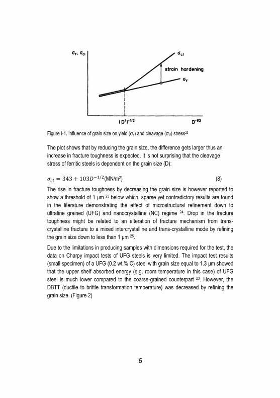
Figure I-1. Influence of grain size on yield (σy) and cleavage (σcl) stress22
The plot shows that by reducing the grain size, the difference gets larger thus an
increase in fracture toughness is expected. It is not surprising that the cleavage
stress of ferritic steels is dependent on the grain size (D):
𝜎𝑐𝑙 = 343 + 103𝐷−1/2(MN/m2) (8)
The rise in fracture toughness by decreasing the grain size is however reported to
show a threshold of 1 μm 23 below which, sparse yet contradictory results are found
in the literature demonstrating the effect of microstructural refinement down to
ultrafine grained (UFG) and nanocrystalline (NC) regime 24. Drop in the fracture
toughness might be related to an alteration of fracture mechanism from trans-
crystalline fracture to a mixed intercrystalline and trans-crystalline mode by refining
the grain size down to less than 1 μm 25.
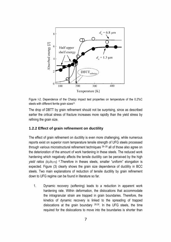
Due to the limitations in producing samples with dimensions required for the test, the
data on Charpy impact tests of UFG steels is very limited. The impact test results
(small specimen) of a UFG (0.2 wt.% C) steel with grain size equal to 1.3 μm showed
that the upper shelf absorbed energy (e.g. room temperature in this case) of UFG
steel is much lower compared to the coarse-grained counterpart 23. However, the
DBTT (ductile to brittle transformation temperature) was decreased by refining the
grain size. (Figure 2)
7
Figure I-2. Dependence of the Charpy impact test properties on temperature of the 0.2%C
steels with different ferrite grain sizes23
The drop of DBTT by grain refinement should not be surprising, since as described
earlier the critical stress of fracture increases more rapidly than the yield stress by
refining the grain size.
1.2.2 Effect of grain refinement on ductility
The effect of grain refinement on ductility is even more challenging, while numerous
reports exist on superior room temperature tensile strength of UFG steels processed
through various microstructural refinement techniques 26–28 all of those also agree on
the deterioration of the amount of work hardening in these steels. The reduced work
hardening which negatively affects the tensile ductility can be perceived by the high
yield ratios (σy/σUTS) 4.Therefore in theses steels, smaller “uniform” elongation is
expected. Figure (3) clearly shows the grain size dependence of ductility in BCC
steels. Two main explanations of reduction of tensile ductility by grain refinement
down to UFG regime can be found in literature so far.
1. Dynamic recovery (softening) leads to a reduction in apparent work
hardening rate. Within deformation, the dislocations that accommodate
the intragranular strain are trapped in grain boundaries. Therefore, the
kinetics of dynamic recovery is linked to the spreading of trapped
dislocations at the grain boundary 29,30. In the UFG steels, the time
required for the dislocations to move into the boundaries is shorter than

8
the time of tensile testing 31. Thus the decrease of dislocation density
inside the grain negatively influences the work hardening in comparison
with coarse-grained steels.
2. Taking the Considère criterion into account, the condition that satisfies
tensile plastic instability is when the work hardening rate (i.e. slope of the
true stress-true strain curve) is equal to the true stress, Eq. (9). At this
point, the uniform elongation is overwhelmed by the neck initiation. 𝑑𝜎𝑡
𝑑𝜀𝑡= 𝜎𝑡 (9)
As discussed above, on one side, UFG steel shows very high flow
stresses at the early stages of plastic deformation but, on the other one,
its work hardening capacity is reduced. As a consequence, the plastic
instability occurs soon after plastic deformation which demolishes the
ductility by suppressing the uniform elongation.
Ma 32, in the frame of an interesting article, has summarized the additional extrinsic
causes to explain low toughness and ductility of UFG and NC materials processed
from powders. A fully dense bulk NC material is very difficult to process. Therefore
poor sample quality leads to very low fracture strength. The residual porosity, weak
interparticle bonding, residual stresses, and impurities would all trigger early plastic
instability and brittle fracture in tension.
Figure I-3. Grain size dependence of ductility in some BCC steels, black symbols represent
uniform elongation and hollow symbols total elongation4

9
1.3 Powder Metallurgy tool steels
The first and foremost distinctive competence which is the driving force for applying
PM processing route for the fabrication of tool steels is the feasibility of avoiding or
minimizing the segregation of carbides (Figure 4). Compared to the conventional
methods such as casting and forming 33,34, PM parts show enhanced strength, wear
resistance and enhanced isotropy. The latter is due to the absence of a continuous
interconnected network of grain boundary carbides that act as preferential paths for
crack propagation which is usually observed in conventional counterparts. (Figure 5 )
Figure I-4. Microstructure of conventional HSS (a) in comparison with PM HSS (b) at the same
magnification, carbides are white in both micrographs
This potential stems from the gas-atomization of the molten batch of pre-alloyed steel
which is characterized by much higher solidification rates compared to conventional
large ingots. Higher solidification rate in small atomized particles opposes the
segregation of carbides. The other advantage of PM route is the capability of
producing parts with complex geometries and with minor material loss and small
machining. The production of PM tool steels has been a topic of both academic and
industrial interest since 70’s 35. Since then, many endeavors have been undertaken
to produce and characterize novel tool steels and tool steel matrix composites via
PM production routes.

10
Figure I-5. Effect of carbide structure on fracture initiation and bend fracture strength
1.3.1 Microstructural refinement of powders and processing of composite powders
Atomized powders can be used in the as-received state for consolidation purposes.
However, the need of microstructural refinement to increase the strength of the
consolidated compact has led to the use of several syntheses and processing
techniques such as high energy Mechanical Milling (MM) to refine both particle size
and microstructure5. The former is generally seen in MM of powders with high
hardness (e.g. tool steel powders) and is a crucial point of attention during sintering,
for the smaller particle size provides a higher driving force for sintering due to the
higher surface energy. Moreover, non-equilibrium solid-state processing techniques
such as Mechanical Alloying (MA) have been introduced to produce a variety of
composite powders showing equilibrium or metastable phases which cannot be
processed using any other technique 36. The other advantages of MA and MM are
the capability of production of bulk quantities of the material at room temperature, by
implementing very simple equipment.
1.3.2 Mechanical Milling and Mechanical Alloying
The ball milling process initially was used to coat hard phases (e.g. WC) with softer
metals (e.g. Ni) 12. It was also reported that the metal powders could undergo
repeated fracturing and cold-welding by the aid of ball milling process. The intense

11
cold working induced by the collision of the balls during MM affects the
thermodynamically stable state of the material by introducing a huge quantity of
lattice imperfections such as dislocations and interfaces at room temperature37,38.
The grain size reduction is characterized by the formation of high energy grain
boundaries in which the atomic arrangement does not own any long or short range
order. Mechanical Milling has been applied successfully to a large number of metallic
powders 6,39,40 to obtain an UFG or nanosized microstructure within the powders. On
the other hand, MA of metal powders (ductile-ductile system) 41 or metallic powders
with ceramic hard particles (ductile-brittle system) 42 have frequently been reported to
yield novel composite materials after proper consolidation. The latter will be briefly
described as it is related to a part of the present work.
As it is shown in Figure (6a), in the first stages of mechanical alloying the ductile
powders get flattened due to the impact of the balls while the brittle HPs are
fragmented. The fine fragmented HPs then are trapped in the lamellas of the ductile
matrix. Upon further milling, the ductile matrix is highly work-hardened and
undergoes fragmentation, and its lamellar microstructure is tangled and refined as
depicted in Figure (6b). In this stage, the actual composition of individual powders
should theoretically approach the nominal mixing composition, and the particle
morphology becomes more or less spherical. By extending the milling time, the
matrix microstructure will be further refined and the second phase (HPs) dispersion
into the matrix becomes more uniform (Figure 6c) giving rise to the formation of
composite powders.
Figure I-6. Microstructural evolution during milling of ductile-brittle combination of powder,a)
ductile powders get flattened and oxides are fragmented and trapped in the matrix, b) ductile
matrix is highly work-hardened ,refined and undergoes fragmentation while oxides are trapped
in the refined lammellas and c) further refinemrnt of matrix microstructure, the figure represents
the specific case of oxide dispersion strengthening 12

12
The major drawback of MA process is the powder contamination during milling 12.
The small size of the powders, large surface area and generation of fresh new
surfaces during the fragmentation process all contribute to the powder
contamination. While too many sources of contamination can be effective during MA,
the primary cause of contamination in most cases is the milling atmosphere. The
leakage of air into the milling container can easily contaminate the powder through
nitrogen and oxygen pick-up. For example, the formation of cubic phase during long
time milling of Ti was evidenced and attributed to the formation of TiN 43. Pellizzari et
al. 44 have also reported oxygen and nitrogen pick-up during ball milling of AISI H13
steel. Oxides can play a detrimental role in consolidation by impeding the strong
interparticle bonding. The presence of oxides might further alter the fracture
mechanism of the consolidated UFG and NC materials, from this viewpoint the
contamination during MA or MM might have a two folded effect on the mechanical
properties of these materials.
1.3.3 Consolidation techniques
Due to the high hardness of atomized tool steel powders and low sintering activity of
these alloys, a fully dense bulk cannot be obtained by conventional pressing and
sintering45. PM Tool steels are mainly produced by Hot Isostatic Pressing (HIP) in
mass production46. New technologies such as hot extrusion sintering, metal injection
molding and spark plasma sintering are considered as attractive routes for the
fabrication of advanced materials with improved mechanical properties44,47.
1.3.3.1 HIP Consolidation
Tool steel inert gas atomized powders are often consolidated using Hot Isostatic
Pressing (HIP) followed by hot forming (e.g. extrusion, forging or rolling) 33,46,48,49.
The technique involves the application of isostatic pressure at high temperatures in a
vessel 50. Encapsulated powders or sintered components thus are densified to yield
more isotropic and improved mechanical properties. Figure (7) shows the density-
temperature maps for various particles sizes of Tool Steel powders HIPed with a
pressure of 100 MPa (i.e. industrial practice).
As it can be deduced from the Figure, the principal mechanism of densification till
reaching a relative density of 98% is the power law creep regime in which the
contribution of applied pressure in densification is the greatest since �̇� ∝ 𝑃𝑛, where
�̇� is the densification rate and P is the applied pressure. The retained porosity (~2%)
is most likely to be removed by the grain boundary diffusion which is mainly

13
dependent on temperature. Holding time helps the promotion of creep and
completion of consolidation.
Figure I-7. Density-temperature maps at P=100 MPa for tool steel with particle sizes of a) 50 μm
and b) 100 μm 46
As reported by Takigawa et al. 51 a near fully dense (~99%) tool steel can be
achieved using different pressure/temperature values in less than 1 hour by HIPing.
However, the response of the sample to mechanical testing is totally different. For
example, in Figure (8a), it can be clearly observed that the fully dense sample HIPed
at 1000°C and 100 MPa is showing an inter-particle fracture suggesting that even if
the applied pressure was high enough to plastically deform the particles and promote
densification, the temperature was not sufficiently high to promote the diffusion for a
complete consolidation and development of strong bonding. On the other hand, the
sample processed at 1200°C and 20 MPa shown Figure (8b) demonstrates an
entirely different fracture surface on which no particle boundary is traceable. The
result suggests that a strong bonding is developed between the powder surfaces
thanks to the processing at higher temperatures.

14
Figure I-8. Fracture surfaces (magnification: 150x) of bend test samples both showing ~99%
relative density, a) 1000°C, 100 MPa and b) 1200°C, 20 MPa 51
Processing at high temperature for longer holding times might be detrimental for the
MM or MA powders which are microstructurally refined down to UFG and NC regime
due to a high probability of recrystallization and grain growth. For instance, a
comprehensive study 52 on annealing the work-hardened MM Fe powders (~HV 950
and crystallite grain size less than 20 nm) suggests that, at a temperature lower than
850°C, 30 minutes of holding is enough to cause local strain relief, followed by
recrystallization and grain growth. A considerable increase in crystallite size was
observed especially at temperatures above 650°C. Therefore, the industrial practice
of HIPing tool steel (i.e. 1100°C, 4 h, 100 MPa) imposes a significant risk of grain
growth and the deterioration of work hardened refined microstructure of MM and MA
powders. While for the latter, the second phase particles added to pin the grain
boundaries might have positive effects on lowering the kinetics of grain growth.
1.3.3.2 Spark Plasma Sintering
A successful alternative approach to consolidate MM or MA steel powders is Spark
Plasma Sintering (SPS) 53–56. Numerous experimental reports suggest that
densification of metal powders and ceramics by SPS can be achieved in shorter
times and at lower temperatures and pressure levels compared to the conventional
Hot Pressing (HP) or HIP 57. The schematic of an SPS apparatus is depicted in
Figure (9).

15
Figure I-9. a) Schematic representation of SPS apparatus 58, b) pulsed current flow through
powder particles 59
SPS is characterized by the consolidation of powders under the concurrent influence
of a low voltage, high current electromagnetic field, and uniaxial pressure. Powders
fill the sintering die (e.g. graphite die) and heating is provided by passing a pulsed
DC (Direct Current) through the die and powders (in the case of sintering of
conductive powders) and uniaxial pressure is simultaneously applied through the
punches. The distinctive competence of SPS compared to HP or HIP includes i)
application of a pulsed DC and ii) high heating rates, which lead to the achievement
of a fully dense material at lower sintering temperatures and shorter times. The
thermal effect of current (i.e. Joule heating) facilitates the achievement of high
heating rates (up to 1000°C/min) that can suppress grain coarsening by by-passing
the surface diffusion mechanism. The efficiency of the process has been pointed up
to the consolidation of refined MM and MA powders while retaining the desirable NC
or UFG microstructure 54,60,61.
The short sintering time might oppose the formation of thermodynamically plausible
parasitic reaction phases at the interface of matrix/reinforcement in MA powders
which may have been otherwise formed by the extension of sintering time. Moreover,
experimental evidence can be found in literature confirming electric field induced
dielectric breakdown of non-conductive surface oxides at the inter-particle contact
areas during spark plasma sintering of metallic powders resulting in enhanced inter-
particle bonding 62–64. Surface cleaning from oxides is of great importance while
dealing with tool steel particles since the risk of surface oxidation is very high even
16
by a careful handling and by using proper protection systems 65,66. Apart from Joule
heating, there is still ambiguity on the inherent characteristics of the electric field on
the processing of conductive and non-conductive materials which is far from the
scope of the present thesis 62.
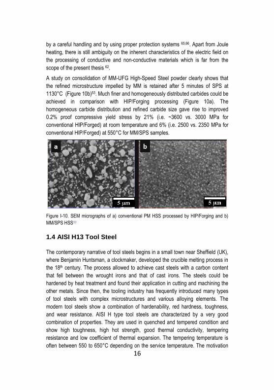
A study on consolidation of MM-UFG High-Speed Steel powder clearly shows that
the refined microstructure impelled by MM is retained after 5 minutes of SPS at
1130°C (Figure 10b)53. Much finer and homogeneously distributed carbides could be
achieved in comparison with HIP/Forging processing (Figure 10a). The
homogeneous carbide distribution and refined carbide size gave rise to improved
0.2% proof compressive yield stress by 21% (i.e. ~3600 vs. 3000 MPa for
conventional HIP/Forged) at room temperature and 6% (i.e. 2500 vs. 2350 MPa for
conventional HIP/Forged) at 550°C for MM/SPS samples.
Figure I-10. SEM micrographs of a) conventional PM HSS processed by HIP/Forging and b)
MM/SPS HSS53
1.4 AISI H13 Tool Steel
The contemporary narrative of tool steels begins in a small town near Sheffield (UK),
where Benjamin Huntsman, a clockmaker, developed the crucible melting process in
the 18th century. The process allowed to achieve cast steels with a carbon content
that fell between the wrought irons and that of cast irons. The steels could be
hardened by heat treatment and found their application in cutting and machining the
other metals. Since then, the tooling industry has frequently introduced many types
of tool steels with complex microstructures and various alloying elements. The
modern tool steels show a combination of hardenability, red hardness, toughness,
and wear resistance. AISI H type tool steels are characterized by a very good
combination of properties. They are used in quenched and tempered condition and
show high toughness, high hot strength, good thermal conductivity, tempering
resistance and low coefficient of thermal expansion. The tempering temperature is
often between 550 to 650°C depending on the service temperature. The motivation

17
behind tempering is to trigger the formation of secondary carbides of the carbide
forming alloying elements (i.e. Cr, Mo, W, and V) which is known as secondary
hardening process. The secondary carbides retard the softening at elevated
temperatures and also guarantee the high hot hardness (strength)67. AISI H13 is a
chromium hot work tool steel which is widely being used as dies for Al or Mg
extrusion, die casting dies, forging dies and tools thanks to its good wear (abrasion)
resistance, high hardness and good toughness.
1.4.1 Research progress in production of UFG PM AISI H13
While a considerable number of research works are dealing with the hot isostatic
pressing of AISI H13 tool steel and tool steel matrix composites 68,69, very limited
attention has been paid to the consolidation of this steel via SPS. The work of
Fedrizzi et al. 70 showed that it was possible to obtain an UFG AISI H13 by short time
SPS of NC and UFG mechanically milled powders. Mechanical Milling of gas
atomized H13 powders was conducted using Fritsch Pulverisette 6 planetary mono
mill at 450 rpm under vacuum. Spheres with 10 mm diameter of 100Cr6 (63HRC)
and a ball to powder weight ratio (BPR) of 10:1 was selected. At the early stages of
the high energy MM (i.e. 200 min), both particle size and crystallite size showed a
sharp reduction. The cellular microstructure of the Atomized powders showing micro-
segregated areas as a consequence of the rapid solidification process was totally
destroyed. Finally, a nearly homogenous UFG lamellar microstructure was achieved.
The continuation of MM resulted in further slight particle size refinement, similarly to
the crystallite size as shown in Figure (11).
Figure I-11. Mean particle size (a) and Crystallite size (b) as a function of milling time70
The powders were then consolidated by SPS at 1100°C for 5 min to yield a UFG
microstructure as depicted in Figure (12b).

18
Figure I-12. SEM micrographs of SPS a) atomized H13 and b) MM-H13 71
The MM-H13 samples showed higher hardness than the atomized counterpart
(Figure 12a) both in as sintered (800 HV10 vs. 640 HV10) and also in heat treated
condition (quenching from 1020°C in a 5bar nitrogen, followed by double tempering
at 625°C). However, a drop in fracture toughness was evidenced (58 MPa m1/2 vs. 77
MPa m1/2). This drop was ascribed to i) the effect of grain size reduction down to
1um, ii) oxygen pick-up during high energy milling that resulted in a higher
concentration of surface oxides impeding the formation of strong metallic bonding,
and iii) the slightly lower relative density of the MM samples compared to the as
atomized ones (99.4% vs. 99.6%) due to the lower compressibility of strain hardened
MM particles.
1.5 Particle reinforced Hot Work Tool Steels
Particle reinforced tool steel matrix composites (MMCs) are developed to increase
the wear resistance of the tool. The designs aim at integrating of the high toughness
of metallic matrix and superior hardness of the hard particles to develop an excellent
wear resistant material 72. A strong motivation behind the production of these
composites is the increasing demand of abrasive wear resistance for dies used in the
extrusion of lightweight metal matrix composites (i.e. Aluminum and Al alloys
reinforced with SiC). The interaction of hard ceramic particles (HPs) with the die can
severely damage and decrease its lifetime. A dramatically high die wear is observed
when processing MMCs using conventional tool steels as die material 73. Pagounis et
al. 69 have shown that the incorporation of 12 vol. % reinforcing particles (i.e. VC or
Cr3C2) in a PM hot work tool steel led to increased three-body abrasive wear
resistance up to seven times, compared to the matrix base material.
Even if PM is more expensive than conventional processing routes such as casting,
the particle reinforced tool steel matrix composites are generally produced via PM
routes due to improved mechanical properties as discussed earlier. The atomized

19
powders are mechanically milled or mixed with the hard particles of the second
phase (i.e. ceramics) in a ball mill or mixer; the powders are then consolidated mostly
using HIPing to obtain a fully dense material18,72.
1.5.1 Role of HPs in Densification of MMCs
In general, the solid state consolidation of MMCs is carried out at sintering
temperatures well below the melting point of HPs. Therefore, the HPs should be
considered as rigid, non-deformable particles during densification. Recalling the
densification mechanism in HIP and SPS (i.e. plastic deformation, power law creep,
grain boundary and bulk diffusion), consolidation of powder blends of HPs and matrix
particles, called soft particles (SPs), is strongly dependent on HPs volume fraction,
size (d), shape and the ratio of (dSP/dHP) 74–76.
At low vol. % of HPs (i.e. isolated HPs), upon application of the pressure at the
processing temperature the matrix particles can deform and fill the holes in the
vicinity of HPs and matrix particles contacts to accomplish the densification. By
increasing the HP volume fraction, the risk of formation of HP aggregates becomes
higher. In this case, filling the holes, namely the excluded volume 77 trapped in
between of rigid HPs by the soft metallic matrix even by the application of high levels
of pressure or long holding times (i.e. long creep time) is almost impossible.
Therefore a fully dense material cannot be achieved. This drawback appears more
detrimental when dealing with a very fine HP size compared to coarser HPs 75.
Upon further increasing the HP's vol. % a percolating HP network might be formed.
The network may partly support the applied external pressure so that the effective
pressure on softer metallic particles will be reduced which in turn leads to hindering
of densification. On the other hand, in this condition, densification might progress by
the rearrangement of the percolated HP network under the applied pressure. The
ease of the rearrangement is dependent on the shape of HPs, the rearrangement of
the spherical particles is easier compared to the irregularly shaped HPs. However,
due to inherent brittleness of HP, rearrangements may be in accompany with HP
fracture and cracking which will consequently demolish the expected mechanical
properties of MMCs under mechanical load.
The vol. % thresholds of the three highlighted conditions (i.e. isolated, aggregated
and percolated HPs) is tightly dependent on the dSP/dHP ratio (Figure 13). Moreover,
since the increased contact area of HPs can hinder the densification in all three
regimes described above, the spherical morphology which offers the lowest contact
area between the hard particles is considered the optimum HP morphology with
regard to ease of densification.

20
Figure I-13. Effect of hard particle volume fraction and particle size ratio on the densification
behavior of hard and soft powder mixtures 78
However, from a mechanical properties viewpoint, the strength of hard ceramic
particles in the metallic matrix is highly dependent on their particle size. In the fine
ceramic particles, the probability of the existence of processing related flaws (i.e.
pores, inclusions and grain boundary fissures) exceeding the critical flaw size is very
low. Therefore according to the Griffith strength formalism 79, the strength of fine HPs
is higher than that of coarser ones. To overcome the percolation and aggregation of
HP’s, MA has been suggested by many researchers as a very efficient technique.
MA provides a very homogeneous distribution of fine HPs in the metallic matrix thus
by-passing the percolation threshold typically found by simple mixing of the powders 56,80–82.
1.5.2 Role of HPs in Mechanical performance of the steel matrix composites
Apart from the governing function of the hardenable metallic matrix, the critical
parameters that influence the mechanical properties of MMCs are briefly described in
the following.
1.5.2.1 HPs size and volume fraction
A fine HP size provides higher strength due to the reduced mean free path between
hard particles. For the same reason, fracture toughness drops significantly. In the
presence of a theoretically clean and seamless interface, when the stress at the

21
poles of the particles becomes high, the crack initiates and easily propagates inside
the HPs. Therefore, at given HP content, the higher the number of HPs the higher
the probability of crack initiation and consequent crack propagation either through the
HPs or HP/Matrix interface 18. Figure (14) schematically depicts the effect of HP size
on the strength and fracture toughness of steel based MMCs. However, the critical
flaw size in ceramic particles should also be considered. The probability of premature
failure (initiated from particles) due to the presence of processing related flaws in
larger ceramic particles is much higher than that of the finer ones 82. Therefore, even
if the schematic presentation in this figure can be assumed for a qualitative
evaluation of strength and toughness, it cannot be a design guideline to produce
MMCs with improved toughness using coarser HP sizes.
Figure I-14. (a) Bend Strength and (b) fracture toughness dependence of MMC on HP size 72
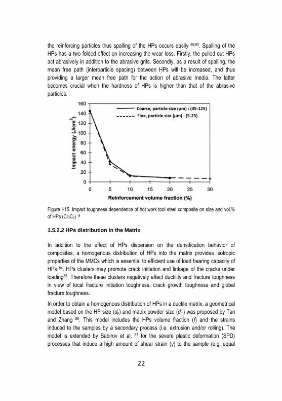
Figure (15) clearly shows the influence of the HPs volume fraction and size on the
impact toughness of hot work tool steel composites. No practical difference in impact
toughness can be observed with regard to the size of the reinforcing particles. This
conveys the fact that the quantity of processing related flaws larger than the critical
flaw size serving as the locations of the initiating defect is much higher inside the
coarse particles. These defects deteriorate the strength of the coarse ceramic
particles and compensate for the positive effect of increased mean free path between
them in view of mechanical properties of the MMCs. Moreover, it is shown that by
increasing the volume fraction of HPs, a drastic drop in toughness is clearly
evidenced. It is also noteworthy to mention that a very high volume fraction of
reinforcement does not necessarily provide better wear resistance in hot work tool
steels. Since in the presence of the secondary carbides, the martensitic matrix will
not be able to support and accommodate excessive volume fractions of the second
phase during the wear test due to the limited toughness, the matrix can not support
22
the reinforcing particles thus spalling of the HPs occurs easily 69,83. Spalling of the
HPs has a two folded effect on increasing the wear loss. Firstly, the pulled out HPs
act abrasively in addition to the abrasive grits. Secondly, as a result of spalling, the
mean free path (interparticle spacing) between HPs will be increased, and thus
providing a larger mean free path for the action of abrasive media. The latter
becomes crucial when the hardness of HPs is higher than that of the abrasive
particles.
Figure I-15. Impact toughness dependence of hot work tool steel composite on size and vol.%
of HPs (Cr3C2) 18
1.5.2.2 HPs distribution in the Matrix
In addition to the effect of HPs dispersion on the densification behavior of
composites, a homogenous distribution of HPs into the matrix provides isotropic
properties of the MMCs which is essential to efficient use of load bearing capacity of
HPs 84. HPs clusters may promote crack initiation and linkage of the cracks under
loading85. Therefore these clusters negatively affect ductility and fracture toughness
in view of local fracture initiation toughness, crack growth toughness and global
fracture toughness.
In order to obtain a homogenous distribution of HPs in a ductile matrix, a geometrical
model based on the HP size (dp) and matrix powder size (dm) was proposed by Tan
and Zhang 86. This model includes the HPs volume fraction (f) and the strains
induced to the samples by a secondary process (i.e. extrusion and/or rolling). The
model is extended by Sabirov et al. 87 for the severe plastic deformation (SPD)
processes that induce a high amount of shear strain (γ) to the sample (e.g. equal
23
channel angular pressing). Based on the model, the HPs distribution is expected to
be homogenous when the HP size (dp) is not smaller than a critical value.
𝑑𝑝 ≥𝑑𝑚
[(𝜋
6𝑓)
13−1]
√𝑅
1−𝑅′𝛾
(10)
where R is the extrusion ratio and R’ reduction ratio during rolling. It appears that the
large shear strains can effectively lower the critical size of HPs needed to achieve a
homogenous distribution into the matrix. It was shown that in an extruded Al6061
powder metallurgy MMC reinforced with 20 vol. % fine Al2O3 particles showing
diffused clusters elongated in the extrusion direction, 7 Passes of ECAP (i.e.
introducing γ to Eq. 10) was sufficient to homogenize the particle distribution within
the matrix87. As a result, the fracture toughness was increased from 1.5 to 2.7 KJ/m2.
Therefore, in order to achieve a homogeneous distribution of fine HPs inside the
matrix, SPD processes seem to be highly efficient.
1.5.2.3 Matrix-Reinforcement Interface
Considering the possible different strengthening mechanisms of HPs in MMCs, load
transfer and matrix strengthening models predominantly rely on the existence of a
defect free and strong matrix/HP interface 88. During solid state processing of
composites, the interface can be classified according to the possible reactions
between HPs and matrix into pure mechanical bond or reaction bond 18,89. As a
general rule, the formation of reaction zones at the interface can significantly affect
the mechanical properties, since most reaction products are brittle 56. However, there
exist sparse results in the literature indicating that the formation of a limited (in size)
reaction zone might improve the bonding between the matrix and the HPs thus
improving the load transfer from matrix to the reinforcement 90.

24
Chapter II The aim of the work
2.1 PM AISI H13 with “Harmonic Microstructure”
As author tried to introduce and rationalize the effect of grain refinement down to
UFG regime on the deterioration of uniform elongation and toughness in ferritic steel,
It would be thus of high industrial importance to imply some metallurgical practices to
overcome ductility problem. One is to produce gradient grain microstructure in which,
only the surface is characterized by (UFG) microstructure and the coarse grain (CG)
core plate provides ductility. This can be achieved by implementing different
mechanical or thermomechanical treatments 91–94. A successful industrial practice is
hot rolling close to the transformation temperature and high rolling strains to achieve
UFG ferrite on the surface down to 0.25 thickness of the strips as a result of strain
induced transformation from austenite to ferrite due to the large strains and high
undercooling 95. Other thermomechanical processes such as cryogenic rolling
followed by secondary recrystallization are useful to produce heterogeneous bimodal
grain materials 96. Bimodal grain size microstructure can also be achieved through
powder processing 97.
In theory, similar to the concept developed by Ashby98 describing the deformation of
plastically non-homogenous materials, the increased strain hardening capability in
these heterogeneous microstructure materials stems from the storage of
geometrically necessary dislocations (dislocations of the same sign). Since the
coarser grains undergo higher plastic deformation than that of the UFGs, there will
be a plastic deformation gradient build up in the microstructure. Accommodation of
this plastic strain gradient requires the storage of geometrically necessary
dislocations. The dislocation density gradient is maximum in case of randomly
distributed CGs that are fully embedded inside the surrounding UFGs 99.
However, when considering the toughness, bimodal grain size materials do not
always show a homogenous behavior due to the inhomogeneous distribution of fine
grains inside the coarse grain matrix 100 or the grain shape and orientation
dependency of toughness in severely plastically deformed grains 24.
An interesting extension to the gradient grains and heterogeneous bimodal grain
size microstructures is realized by a powder metallurgical production route leading to
25
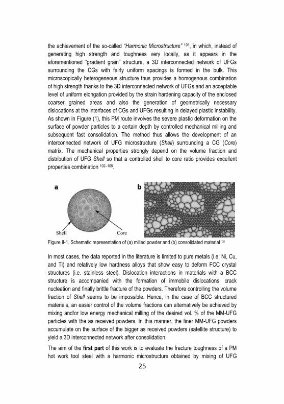
the achievement of the so-called “Harmonic Microstructure” 101, in which, instead of
generating high strength and toughness very locally, as it appears in the
aforementioned “gradient grain” structure, a 3D interconnected network of UFGs
surrounding the CGs with fairly uniform spacings is formed in the bulk. This
microscopically heterogeneous structure thus provides a homogenous combination
of high strength thanks to the 3D interconnected network of UFGs and an acceptable
level of uniform elongation provided by the strain hardening capacity of the enclosed
coarser grained areas and also the generation of geometrically necessary
dislocations at the interfaces of CGs and UFGs resulting in delayed plastic instability.
As shown in Figure (1), this PM route involves the severe plastic deformation on the
surface of powder particles to a certain depth by controlled mechanical milling and
subsequent fast consolidation. The method thus allows the development of an
interconnected network of UFG microstructure (Shell) surrounding a CG (Core)
matrix. The mechanical properties strongly depend on the volume fraction and
distribution of UFG Shell so that a controlled shell to core ratio provides excellent
properties combination 102–105.
Figure II-1. Schematic representation of (a) milled powder and (b) consolidated material106
In most cases, the data reported in the literature is limited to pure metals (i.e. Ni, Cu,
and Ti) and relatively low hardness alloys that show easy to deform FCC crystal
structures (i.e. stainless steel). Dislocation interactions in materials with a BCC
structure is accompanied with the formation of immobile dislocations, crack
nucleation and finally brittle fracture of the powders. Therefore controlling the volume
fraction of Shell seems to be impossible. Hence, in the case of BCC structured
materials, an easier control of the volume fractions can alternatively be achieved by
mixing and/or low energy mechanical milling of the desired vol. % of the MM-UFG
particles with the as received powders. In this manner, the finer MM-UFG powders
accumulate on the surface of the bigger as received powders (satellite structure) to
yield a 3D interconnected network after consolidation.
The aim of the first part of this work is to evaluate the fracture toughness of a PM
hot work tool steel with a harmonic microstructure obtained by mixing of UFG
26
mechanically milled (MM) and coarser grained as atomized (AT) powders
consolidated by SPS. In a second step, the best performing harmonic microstructure
has been subjected to thermal fatigue testing. Considering the industrial application
of hot work tool steel for hot forging and die casting, surface damages by heat
checking most likely occurs 107,108. Heat checks are defined as a network of surface
cracks which are formed because of the fatigue developed upon the repetition of
thermal stresses. These stresses are generated because the expansion and
contraction of the surface during heating and cooling is constrained by the core.
Crack initiation at the surface of the tool impairs surface finishing and forces repairing
operations. A deep propagation of these cracks may eventually trigger the tool
failure. Resistance to heat checking can be improved by a combination of hot
strength, ductility, and toughness together with inherent high thermal conductivity
and low coefficient of thermal expansion. Thermal fatigue resistance evaluation of a
harmonic microstructure can then be then of interest in its potential industrial
application where the tool has to show a combination of high toughness and
reasonable hardness together with high TF resistance. Therefore, the TF resistance
of the harmonic PM AISI H13 tool steel is also investigated using a simple TF test
equipment.
2.2 PM AISI H13-PSZ composites
Previous studies confirmed that the failure of MMCs with a high strength matrix
initiates predominantly either from the HP or matrix-reinforcement interface 10,18,109.
Moreover, the difference between the coefficient of thermal expansion of matrix and
reinforcement generates a hydrostatic tensile field of stress in the matrix upon
cooling from the processing temperature, which in turn deviates the crack towards
the matrix/reinforcement interface and lowers the fracture toughness 69. One way to
reduce the negative influence of the reinforcement on toughness is to select
“Ceramic Materials” with relatively high stress to fracture and high fracture
toughness.
Partially stabilized Zirconia (PSZ), firstly introduced by Garvie et al.110 showed
promising properties. Below 1170 °C, ZrO2 transforms from the tetragonal phase (t)
into a monoclinic structure (m), accompanied by 3% to 5% volume expansion. In
PSZ, by using dopants (e.g. Y2O3 or MgO) the tetragonal phase will be metastable at
room temperature and shows stress-induced martensitic transformation into the
monoclinic structure. In view of the aforementioned feature, PSZ shows higher
fracture toughness (i.e. K IC ~ 8 MPa m1/2) in comparison with other ceramics as a
result of the dissipation of the strain energy in the vicinity of the tip of a propagating
crack due to the stress-induced transformation of the metastable tetragonal phase (t)

27
into the stable monoclinic one (m). Another toughening mechanism has been
ascribed to the creation of compressive strain fields about the crack tip, due to the
volume expansion resulting from t to m transformation, that opposes crack
propagation 111. In a PSZ containing composite, the effective volumetric
transformation strain (θT) is defined by Eq. 1 112
𝜃𝑇 = 𝐶𝜃𝑇𝑃 (1)
where C is the volume fraction of transforming particles and 𝜃𝑇𝑃 is the volumetric
transformation strain of the particles when the particles are not constrained by the
matrix. In a composite material containing small vol. % of transforming phase (i.e.
PSZ), the effective volumetric transformation strain will be enhanced if the matrix
material is not stiffer than PSZ (E ~ 210 GPa , ν = 0.3)111,112. The energy-dissipative
stress induced phase transformation of PSZ thus can be expected to enhance the
toughness of the tool steel matrix composite (Ematrix ~ 208 GPa) in comparison with
the same tool steel reinforced with other ceramic compounds.
Partially stabilized zirconia shows much higher hardness compared to the metals. A
good combination of both hardness and fracture toughness makes it a proper
candidate as a tribological material 113. PSZ shows the potential to enhance the
abrasive wear resistance of the MMC more than other ceramic compounds not
showing such kind of transformation. If there exists a strong bonding between PSZ
and the matrix, volume expansion caused by phase transformation creates
compressive zones at the tip of the propagating cracks which in turn opposes the
linking up of these cracks and delays the particle removal by fracture 114.
The strengthening mechanism of PSZ in a metallic matrix was investigated by Martin
et al. 115. Incorporation of PSZ into a TRIP steel matrix led to an increase in the
strength of the composite material with reference to the unreinforced alloy and also in
comparison with the TRIP steel reinforced with a conventional HP (i.e. Al2O3). The
load transfer to PSZ particles and energy dissipation due to the stress induced
transformation before particle fracture or particle debonding was also well
documented 115–117.
In the frame of the second part of the present work, the feasibility and mechanical
properties of a tool steel matrix-PSZ composite by mechanical alloying and spark
plasma sintering has been evaluated. Two different types of zirconia and different
volume fractions of reinforcement is taken into consideration. Mechanical Milling is
carried out to achieve a full dispersion of hard particles into the severely deformed
tool steel matrix to pursue the synergistic effects of i) strain hardening and
microstructural refinement due to severe plastic deformation and ii) dispersion
hardening by HPs.

28
Chapter III Materials and Experimental Procedures
3.1 Materials and fabrication of samples
3.1.1 Harmonic microstructure design
To tailor the feasibility of development of a Core/Shell Structure in AISI H13 gas
atomized powders, controlled mechanical milling was performed. A commercial gas
atomized AISI H13 powder (Table 1) was used.
Table III-1. Chemical composition of AISI H13 powder (wt. %)
𝐅𝐞 𝐂 𝐂𝐫 𝐌𝐨 𝐕 𝐌𝐧 𝐒𝐢 N* O*
AISI H13 Bal. 0.41 5.1 1.6 1.1 0.35 0.9 383 105
*in ppm
Particles showed an average size of 100 μm and the maximum particle size was
lower than 150 µm. The initial micro-hardness was 710 HV0.1, in agreement with the
martensite (plus some retained austenite) microstructure obtained during rapid
solidification. A first powder batch was used in the as-atomized state (AT) while a
second one was annealed (AN) to reduce hardness and to improve the strain
hardening capability. Annealing was performed in a tubular furnace (Alumina tube) in
a reducing atmosphere (20% H2 and 80% Ar). Preheating rate was 0.5 °C/min up to
200°C, and powders were heated at a rate of 3.5 °C/min up to 860°C. Dwell time
was set to 2 hours followed by slow cooling (0.5 °C/min) down to 560°C and
subsequent free cooling to room temperature.
Powders were then subjected to low energy (controlled) mechanical milling using a
Fritsch Pulverisette 6 planetary mono mill with a 500 ml vial using 100Cr6 steel balls
under vacuum at room temperature for 16 hours. Parameters of the rotational speed
(RPM) and ball to powder weight ratio (BPR) were chosen in order to reduce the
29
frequency of high energy impacts to avoid powder fragmentation during mechanical
milling. Therefore, as suggested in previous research works118,119 the ball to powder
ratio was set to 1.5:1(g/g) and the rotational speed of 150 rpm.
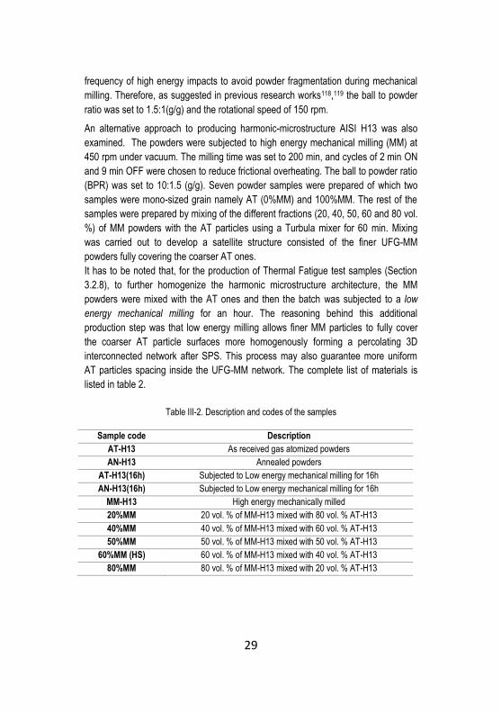
An alternative approach to producing harmonic-microstructure AISI H13 was also
examined. The powders were subjected to high energy mechanical milling (MM) at
450 rpm under vacuum. The milling time was set to 200 min, and cycles of 2 min ON
and 9 min OFF were chosen to reduce frictional overheating. The ball to powder ratio
(BPR) was set to 10:1.5 (g/g). Seven powder samples were prepared of which two
samples were mono-sized grain namely AT (0%MM) and 100%MM. The rest of the
samples were prepared by mixing of the different fractions (20, 40, 50, 60 and 80 vol.
%) of MM powders with the AT particles using a Turbula mixer for 60 min. Mixing
was carried out to develop a satellite structure consisted of the finer UFG-MM
powders fully covering the coarser AT ones.
It has to be noted that, for the production of Thermal Fatigue test samples (Section
3.2.8), to further homogenize the harmonic microstructure architecture, the MM
powders were mixed with the AT ones and then the batch was subjected to a low
energy mechanical milling for an hour. The reasoning behind this additional
production step was that low energy milling allows finer MM particles to fully cover
the coarser AT particle surfaces more homogenously forming a percolating 3D
interconnected network after SPS. This process may also guarantee more uniform
AT particles spacing inside the UFG-MM network. The complete list of materials is
listed in table 2.
Table III-2. Description and codes of the samples
Sample code Description
AT-H13 As received gas atomized powders
AN-H13 Annealed powders
AT-H13(16h) Subjected to Low energy mechanical milling for 16h
AN-H13(16h) Subjected to Low energy mechanical milling for 16h
MM-H13 High energy mechanically milled
20%MM 20 vol. % of MM-H13 mixed with 80 vol. % AT-H13
40%MM 40 vol. % of MM-H13 mixed with 60 vol. % AT-H13
50%MM 50 vol. % of MM-H13 mixed with 50 vol. % AT-H13
60%MM (HS) 60 vol. % of MM-H13 mixed with 40 vol. % AT-H13
80%MM 80 vol. % of MM-H13 mixed with 20 vol. % AT-H13
30
3.1.2 AISI H13 Tool Steel-PSZ composites
Commercial AISI H13 tool steel powder (d < 45μm) was selected as the matrix
material (Table 3). Two different types of PSZ particles, namely Magnesia Partially
Stabilized Zirconia (Mg-PSZ) and a commercial 3 mol. % Yttria Stabilized Zirconia
(from now on referred to as 3Y-PSZ) with mean particle sizes equal to 5 and 0.5 μm
respectively (Table 4), were selected as the reinforcement.
Table III-3. Chemical composition of AISI H13 (wt. %)
𝐅𝐞 𝐂 𝐂𝐫 𝐌𝐨 𝐕 𝐌𝐧 𝐒𝐢 𝐎
AISI H13 Bal. 0.38 5.1 1.0 1.4 0.35 1.0 0.05
Table III-4 Chemical composition of reinforcement (wt. %)
𝐙𝐫𝐎𝟐
+ 𝐇𝐟𝐎𝟐
𝐘𝟐𝐎𝟑 𝐒𝐢𝐎𝟐 𝐅𝐞𝟐𝐎𝟑 𝐀𝐥𝟐𝐎𝟑 𝐍𝐚𝟐𝐎 𝐌𝐠𝐎 𝐓𝐢𝐎𝟐
3Y-PSZ Bal. 5.23 0.003 0.002 0.005 0.007 N/A N/A
Mg-PSZ Bal. N/A 0.025 0.005 N/A 0.006 3.5 1.0
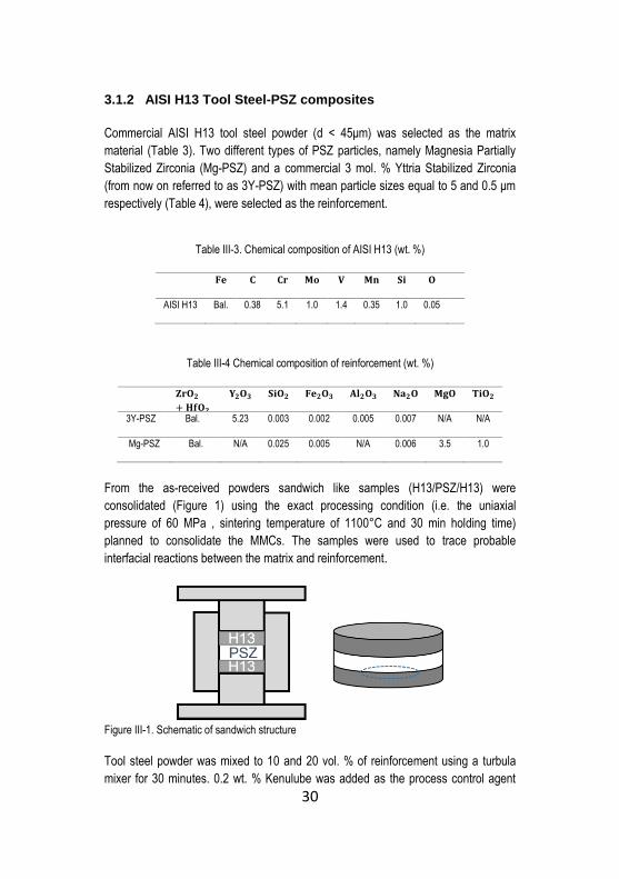
From the as-received powders sandwich like samples (H13/PSZ/H13) were
consolidated (Figure 1) using the exact processing condition (i.e. the uniaxial
pressure of 60 MPa , sintering temperature of 1100°C and 30 min holding time)
planned to consolidate the MMCs. The samples were used to trace probable
interfacial reactions between the matrix and reinforcement.
Figure III-1. Schematic of sandwich structure
Tool steel powder was mixed to 10 and 20 vol. % of reinforcement using a turbula
mixer for 30 minutes. 0.2 wt. % Kenulube was added as the process control agent
31
(PCA). The powder mixture was then mechanically alloyed (MA) using a planetary
mono mill under vacuum at a rotational speed of 450 rpm. The ball to powder ratio
(BPR) was set to 10:1.5 (g/g). Milling was extended up to 340 minutes, and powders
were collected after 90 min, 200 min and 340 min of milling to determine the optimum
processing time. Cycles of 2 min ON (i.e. milling) and 9 min OFF (i.e. stop) were
selected to avoid overheating. Air cooling suppressed drastic variations in vial
temperature.
For the purpose of comparison, a TiC reinforced H13 were also produced under the
same processing condition. The mean particle size of TiC powder was 3 μm. A list of
developed composites specifying the reinforcement type, vol. % and mean particle
size is listed in table 5.
Table III-5 composition and codes of MA powders
Sample code Reinforcement
vol. %
Reinforcement
type
Reinforcement
Mean particle
size (μm)
MA(H13+10%Mg-PSZ) 10 Mg-PSZ 5
MA(H13+20%Mg-PSZ) 20 Mg-PSZ 5
MA(H13+10%3Y-PSZ) 10 3Y-PSZ 0.5
MA(H13+20%3Y-PSZ) 20 3Y-PSZ 0.5
MA(H13+20%TiC)* 20 TiC 3
* TiC reinforced H13 (i.e. MA(H13+20%TiC)) serving as a reference tool steel composite
produced in lab of metallurgy using the same technique was just evaluated by means of
fracture toughness and hardness
3.1.3 Spark Plasma Sintering
All Powders in this work were consolidated using a DR. SINTER® SPS1050
apparatus (Sumitomo Coal & Mining, now SPS Syntex Inc.) using graphite dies. The
disc-shaped samples with small dimensions (20 mm in diameter, 7 mm in height)
were heated at 100 °C/min up to the sintering temperature (1100°C) and were held
for 30 minutes. A pressure of 60 MPa was applied once the temperature reached
570°C. The samples were free cooled from the sintering temperature. Due to the
limitation of the apparatus, heating rate could not exceed 50 °C/min for relatively
large samples. Therefore, disks for the plane strain fracture toughness tests (30 mm
in diameter and 7 mm height) and Thermal Fatigue test (40mm diameter and 20mm
height) were consolidated using a lower heating rate (i.e. 50 °C/min).
Overall views of the production of harmonic microstructure and tool steel-PSZ
composites are schematically shown in Figures (2a) and (2b) respectively.
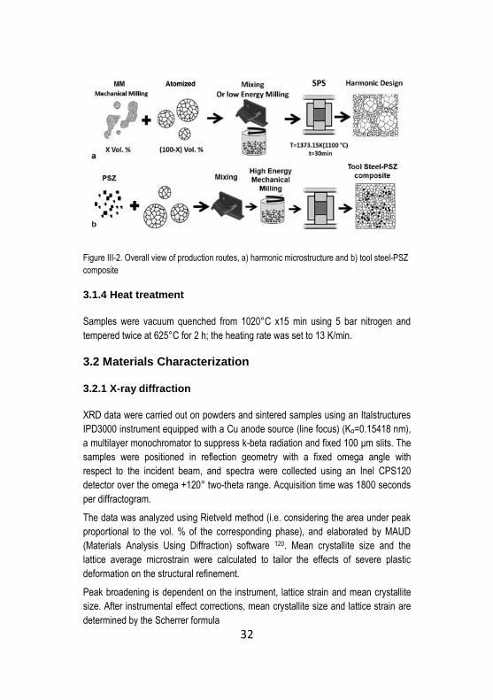
32
Figure III-2. Overall view of production routes, a) harmonic microstructure and b) tool steel-PSZ
composite
3.1.4 Heat treatment
Samples were vacuum quenched from 1020°C x15 min using 5 bar nitrogen and
tempered twice at 625°C for 2 h; the heating rate was set to 13 K/min.
3.2 Materials Characterization
3.2.1 X-ray diffraction
XRD data were carried out on powders and sintered samples using an Italstructures
IPD3000 instrument equipped with a Cu anode source (line focus) (Kα=0.15418 nm),
a multilayer monochromator to suppress k-beta radiation and fixed 100 μm slits. The
samples were positioned in reflection geometry with a fixed omega angle with
respect to the incident beam, and spectra were collected using an Inel CPS120
detector over the omega +120° two-theta range. Acquisition time was 1800 seconds
per diffractogram.
The data was analyzed using Rietveld method (i.e. considering the area under peak
proportional to the vol. % of the corresponding phase), and elaborated by MAUD
(Materials Analysis Using Diffraction) software 120. Mean crystallite size and the
lattice average microstrain were calculated to tailor the effects of severe plastic
deformation on the structural refinement.
Peak broadening is dependent on the instrument, lattice strain and mean crystallite
size. After instrumental effect corrections, mean crystallite size and lattice strain are
determined by the Scherrer formula

33
𝐵 =0.9𝜆
𝑑𝑐𝑜𝑠(𝜃)+ 𝜂𝑡𝑔(𝜃) (1)
where B is the width of the peak at half of its height, λ is the radiation wavelength, d
is the crystallite size, η is the lattice strain, and θ is the Bragg angle. The equation
can be rearranged by multiplying both sides by cos (θ) to give a linear function of θ
𝐵𝑐𝑜𝑠(𝜃) = (0.9𝜆
𝑑) + 𝜂 sin (𝜃) (2)
where the slope (η) is the lattice strain. This method can be applied if the crystallite
size distribution lies in the range of 10-100 nm12.
3.2.2 Density measurements
Density measurements were done on as sintered specimen according to the
“Archimedes” principle conforming to ASTM B962-08 121. The density of AISI H13
was considered to be 7.76 g/cm3.
The density of composites was assumed to obey the linear “ rule of mixtures.”
𝜌𝑐𝑜𝑚𝑝𝑜𝑠𝑖𝑡𝑒 = 𝜌𝐻13𝑣𝐻13 + 𝜌𝑟𝑒𝑖𝑛𝑓𝑜𝑟𝑐𝑒𝑚𝑒𝑛𝑡𝑣𝑅𝑒𝑖𝑛𝑓𝑜𝑟𝑐𝑒𝑚𝑒𝑛𝑡 (3)
where ρ and v are the absolute density and volume fraction respectively. The
literature data on the absolute densities of 3Y-PSZ ( 6.05 g/cm3 ) and Mg-PSZ (5.7
g/cm3 ) were used.
3.2.3 Metallography
Sintered samples were cut by precision micro-cutting with a diamond blade.
Metallographic sections were prepared by grinding with SiC papers up to 1200 grit
followed by polishing with 3 μm and 1 μm diamond paste and chemical etching with
Nital (5% nitric acid in ethanol solution) was carried out on sintered samples and
powders. Sintered samples Microstructures and powder morphologies were
investigated by Scanning Electron Microscopy (SEM). All semi-qualitative chemical
analyses were performed by energy-dispersive X-ray spectroscopy (EDS). EDS line
scan analysis and elemental mapping was carried out on sandwich samples and
consolidated composites respectively to identify the possible formation of reaction
layers.
3.2.4 Grain size measurement
Quantitative image analysis using the linear intercept method on SEM micrographs
was implemented to measure the grain size of the samples. The results were
elaborated according to ASTM E112-13.

34
3.2.5 Hardness measurements
Vickers hardness measurements on as sintered and heat treated samples was
performed according to ASTM E92-82 122. The applied load was set to 10 Kg and the
average of at least six indentations was reported.
Microhardness test was performed on the metallographic samples. Applied load was
set to 0.05 N for the powders in order to eliminate the influence of the substrate. The
load was set to 0.1 N for the bulks.
3.2.6 Measurement of yield strength
The yield strength of the harmonic microstructure samples was measured using
spherical indentation according to the empirical method proposed by Herbert et al. 123. The technique gives a good estimation of the yield stress for materials showing
small yield strain (less than 1%) in which, yielding occurs well before any finite-
deformation effects 124. The advantages of this method are its nondestructive
characteristics, relatively low cost and the possibility of applying the test on the small
samples. For the construction of “stress-strain curves,” the contact area during
indentation has been calculated by the following equation
𝑎 = √2ℎ𝑐𝑅 − ℎ𝑐2 (4)
where a is the contact radius, hc is half the amount of h, the total displacement of the
indenter into the sample, and R being the radius of the spherical indenter using the
Hertz solution which is proved to be algebraically straightforward and precise in this
context123. According to the observations of Tabor125 and using Eq.5, it is possible to
define the mean pressure (Pm) as the applied load (P) over the contact area.
𝑃𝑚 =𝑃
𝜋𝑎2 (5)
Following the work of Mesarovic and Fleck 124, the yield is observed when (a/R) (i.e.
contact area divided by indenter radius) approaches 0.16, this ratio is independent of
the magnitude of σy , Young’s modulus, and Poisson’s ratio. At this point, the mean
pressure (Pm= P/ πa2) divided by 1.6, somewhat estimates the yield point of the
material 123.
The stress and strain in the uniaxial tensile test are equivalent to:
𝜎𝑖𝑛𝑑𝑒𝑛𝑡𝑎𝑡𝑖𝑜𝑛 ≈𝑃𝑚
𝜓≈ 𝜎𝑢𝑛𝑖𝑎𝑥𝑖𝑎𝑙 𝑡𝑒𝑛𝑠𝑖𝑙𝑒 𝑡𝑒𝑠𝑡 (6)
𝜀𝑖𝑛𝑑𝑒𝑛𝑡𝑎𝑡𝑖𝑜𝑛 ≈ 0.2𝑎
𝑅 ≈ 𝜀𝑢𝑛𝑖𝑎𝑥𝑖𝑎𝑙 𝑡𝑒𝑛𝑠𝑖𝑙𝑒 𝑡𝑒𝑠𝑡 (7)
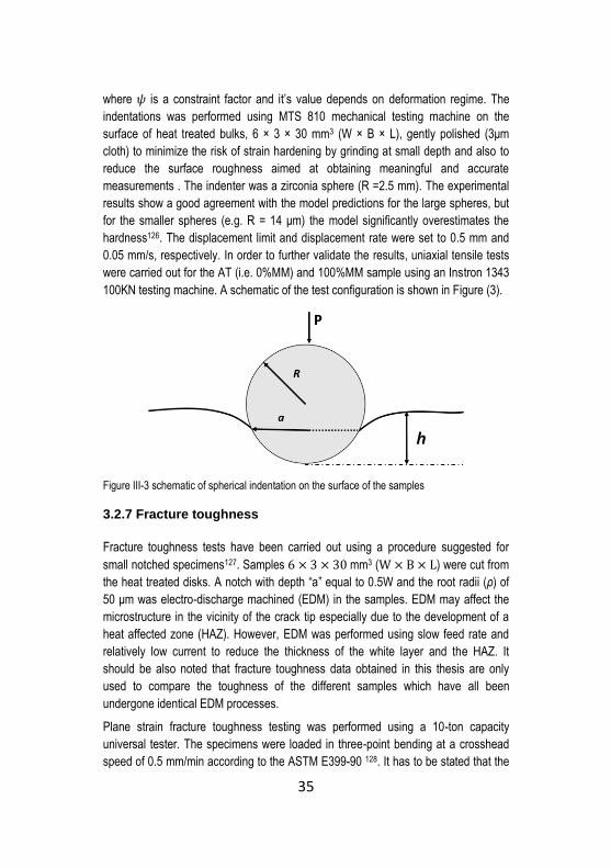
35
where 𝜓 is a constraint factor and it’s value depends on deformation regime. The
indentations was performed using MTS 810 mechanical testing machine on the
surface of heat treated bulks, 6 × 3 × 30 mm3 (W × B × L), gently polished (3μm
cloth) to minimize the risk of strain hardening by grinding at small depth and also to
reduce the surface roughness aimed at obtaining meaningful and accurate
measurements . The indenter was a zirconia sphere (R =2.5 mm). The experimental
results show a good agreement with the model predictions for the large spheres, but
for the smaller spheres (e.g. R = 14 μm) the model significantly overestimates the
hardness126. The displacement limit and displacement rate were set to 0.5 mm and
0.05 mm/s, respectively. In order to further validate the results, uniaxial tensile tests
were carried out for the AT (i.e. 0%MM) and 100%MM sample using an Instron 1343
100KN testing machine. A schematic of the test configuration is shown in Figure (3).
Figure III-3 schematic of spherical indentation on the surface of the samples
3.2.7 Fracture toughness
Fracture toughness tests have been carried out using a procedure suggested for
small notched specimens127. Samples 6 × 3 × 30 mm3 (W × B × L) were cut from
the heat treated disks. A notch with depth “a” equal to 0.5W and the root radii (ρ) of
50 μm was electro-discharge machined (EDM) in the samples. EDM may affect the
microstructure in the vicinity of the crack tip especially due to the development of a
heat affected zone (HAZ). However, EDM was performed using slow feed rate and
relatively low current to reduce the thickness of the white layer and the HAZ. It
should be also noted that fracture toughness data obtained in this thesis are only
used to compare the toughness of the different samples which have all been
undergone identical EDM processes.
Plane strain fracture toughness testing was performed using a 10-ton capacity
universal tester. The specimens were loaded in three-point bending at a crosshead
speed of 0.5 mm/min according to the ASTM E399-90 128. It has to be stated that the

36
use of a finite notch radius in place of a fatigue pre-crack, takes higher stress to
reach the “critical stress intensity,“ therefore leading to apparent Kapp values slightly
greater than the corresponding KIC obtained from fatigue pre-cracked specimen.
3.2.8 Thermal Fatigue test
Thermal fatigue testing was performed on three samples, namely the harmonic
microstructure that showed the optimized mechanical properties, 100% UFG-MM
and 0% MM (AT).
Dimensional specifications are shown in Figure (4). The thickness of the disk (20
mm) made it possible to develop a biaxial state of stress and bidirectional cracking
on the surface. A condition which is similar to that observed in many industrial
components 129.
Figure III-4. Technical drawing of disks
TF tests were performed using a customary test rig as depicted in Figure (5). The
rotating disc (8 rev/min) was induction-heated in a limited central portion of the
external surface up to 660±10°C (i.e. higher than the tempering temperature of the
samples) and rapidly cooled by a water jet (2l/min) down to 60°C. A beaker,
continuously filled with flowing water, was also placed beneath the rotating disk to
warranty the minimum temperature to be achieved. An infrared pyrometer
continuously monitored the surface temperature.
Tests were interrupted after 200 and 500 cycles to evaluate surface thermal cracking
after slightly polishing of the surface oxide layer. After 500 cycles metallographic
cross sections parallel and perpendicular to the rotation direction were prepared to
be analyzed by scanning electron (SEM) and optical microscopy (OM). The mean
crack length (lm), maximum crack length (lmax), crack density (ρ) and the product of
these parameters, i.e. the so-called Pyrocracking factor (P) 129 were calculated using
quantitative image analysis. For this purpose only cracks longer than 20 μm were
taken into account.

37
Figure III-5. Schematic view of the test rig
3.2.9 High-temperature chemical stability of composites
The chemical stability at the processing temperature was further studied by holding
the consolidated samples at the SPS temperature (1100°C) under vacuum (5×10⁻⁴
mbar) for longer dwell times (i.e. 1 and 2 hours). The metallographic cross-sections
were analyzed using EDS semi-quantitative analysis.
3.2.10 Tempering resistance
Tempering resistance testing was performed on cylinderes (10 mm in height , 5 mm
in diamater) at 550°C and 650°C under vacuum (5×10⁻⁴ mbar), for a maximum
holding time of 10 hours.
3.2.11 Hot Compression Tests
Cylindrical samples were extracted by electro-discharge machining (EDM) from the
sintered cylinders, with the main axis along the pressing direction. Hot compression
tests were carried out on these cylinders using a Bähr dilatometer model 805A/D at
650°C, 450°C and room temperature at a strain rate of 0.002 s-1 to 6% plastic strain.

38
Chapter IV Results and Discussion
Part of this chapter has been published in:
F. Deirmina, M. Pellizzari, and M. Federici
“Production of a Powder Metallurgical Hot Work Tool Steel with Harmonic Structure by Mechanical Milling and Spark Plasma Sintering”, Metall. Mater. Trans. A, vol. 48, no. 4, pp. 1910–1920, Apr. 2017. F. Deirmina, M. Pellizzari
"Thermal fatigue resistance of a PM tool steel with bimodal grain size", Proc. of 10th TOOL Conference, ASMET, the Austrian Society for Metallurgy and Materials, 4-7 October 2016, Bratislava, Slovakia, ISBN : 978-3-200-04786-0. F. Deirmina, M. Pellizzari
“Production and characterization of a tool steel-PSZ composite by mechanical alloying and spark plasma sintering”, J. Alloys Compd., vol. 709, pp. 742–751, Jun. 2017.
F. Deirmina, M.Pellizzari
“Production of HWTS (AISI H13) Matrix Composite Reinforced With Partially Stabilized Zirconia”, Proc. of the World PM 2016 Congress & Exhibition 9-13 October, Hamburg, Germany, ISBN: 978-1-899072-47-7. M. Pellizzari, F. Deirmina, "POWDER METALLURGY OPENS NEW WAYS FOR TOOL STEELS," (In press), International Journal of Microstructure and Materials Properties
Part 1
4.1 Harmonic structure design by low energy MM
Figure (1) shows SEM micrographs of the starting powders. The AT powder
evidences the typical microstructure from rapid solidification, composed by primary
martensite and retained austenite 71 (Figure 1a). Its hardness is rather high (712

39
HV0.05). Highly segregated areas can be detected in the intercellular regions. On the
other hand, the annealed powders show carbide distribution mostly at prior
intercellular regions, due to the local positive micro-segregation of carbide forming
elements (Figure 1b). As a result of recrystallization, the hardness of the annealed
powder is very low (190 HV0.05).
Figure IV-1. SEM micrographs of a) Gas Atomized (AT) powder and b) Annealed Powder (AN),
(nital 5%)
Figure (2) shows the powders microstructure after 16 hours of mechanical milling.
The hard (AT) particles show a visible deformed surface (Figure 2a) which can be
recognized by the change in grain shape aspect ratio (i.e. prior austenite grain
boundaries). The degree of straining gradually decreases towards the core. As a
result of the lower hardness the (AN) particles (Figure 2b), experienced a much more
severe surface plastic deformation.
Figure IV-2. SEM micrographs showing the development of SHELL in a) (AT) and b) (AN)
particles, (nital 5%)
Grain boundaries are difficult to be distinguished and the precipitated carbides, at the
intercellular region, which act elastically against the impacts are forced to accumulate

40
and align tangentially to the surface of the (AN) particles (Figure 3). There also exists
evidence of cracked carbides in the deformed matrix and voids that are initiated at
the carbides and matrix interfaces. In both cases, the fraction of the microstructurally
refined surface is about 10 vol. % of the entire particle.
Figure IV-3. SEM micrograph showing the core/shell structure in (AN) powders, arrows
indicating cracked carbides and generated void, (nital 5%)
XRD patterns of the four samples are shown in Figure (4), peak broadening is
evidenced in both mechanically milled samples with respect to the un-milled ones.
Moreover, It can be observed that γ (retained austenite) peaks are not present in
collected spectra of AT sample milled for 16 h as an indicative of strain induced
martensitic transformation in the shell area (Figure 4a). Since the penetration depth
of Cu-Kα radiation in steel particles does not exceed more than a few microns 130, it
is possible to assume that the collected data accounts for the severely deformed
shell of (AT) and (AN) powders.
Figure IV-4. XRD patterns of a) AN and AN milled for 16 h, b) AT and AT milled for 16 h
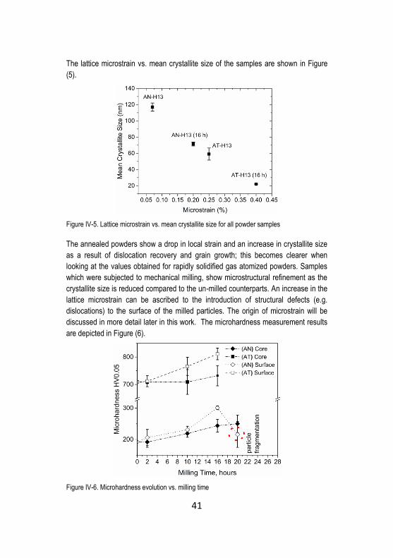
41
The lattice microstrain vs. mean crystallite size of the samples are shown in Figure
(5).
Figure IV-5. Lattice microstrain vs. mean crystallite size for all powder samples
The annealed powders show a drop in local strain and an increase in crystallite size
as a result of dislocation recovery and grain growth; this becomes clearer when
looking at the values obtained for rapidly solidified gas atomized powders. Samples
which were subjected to mechanical milling, show microstructural refinement as the
crystallite size is reduced compared to the un-milled counterparts. An increase in the
lattice microstrain can be ascribed to the introduction of structural defects (e.g.
dislocations) to the surface of the milled particles. The origin of microstrain will be
discussed in more detail later in this work. The microhardness measurement results
are depicted in Figure (6).
Figure IV-6. Microhardness evolution vs. milling time

42
The shell microhardness gradually increases by extending the milling time up to 16 h.
As mentioned earlier, at this stage of milling, around 10 vol. % of the particles was
severely deformed and microstructurally refined. By further extending the milling
time, a drop in the shell micro-hardness is evidenced, in line with the SEM
observations showing particle fragmentation after 20 h of mechanical milling (see
Figure 7).
Figure IV-7. SEM micrograph showing the fragmentation after 20 h of milling in (AN) powders,
(nital 5%)
The results thus suggest that in AISI H13 powder particles controlling the shell vol. %
is rather hard or even impossible. To explain such behavior, one has to refer to the
dislocation interactions in BCC structured materials. In a BCC structure material, the
interaction of dislocations to generate a new dislocation with multiple Burgers vector
of type <100> might nucleate a cleavage crack. However, there is strong evidence
that the dislocations interaction cannot provide a stress concentration sufficient for a
cleavage crack nucleation 131. Therefore, the role of the carbides should also be
taken into account 131. As the surface of the particle is plastically deformed, at a
certain level of strain hardening, a crack might nucleate in the carbides; the crack
reaches the interface of carbide and strain hardened ferrite. Since strain hardened
ferrite is not able to accommodate the plastic strain in the stress concentration site at
the tip of the crack, the crack can be considered as a Griffith flaw. Therefore, once
the length of these micro-cracks (i.e. cracking of coarse carbides or carbide films in
the prior intercellular regions) reaches the critical length, because of the very slow
velocity of dislocation movement in readily work hardened BCC ferrite 132, the crack
will propagate by cleavage on the (001) plane. Another probability is to assume that
the generated voids at the carbide/matrix interface acted as preferred sites for crack
nucleation and subsequent cleavage fracture133.
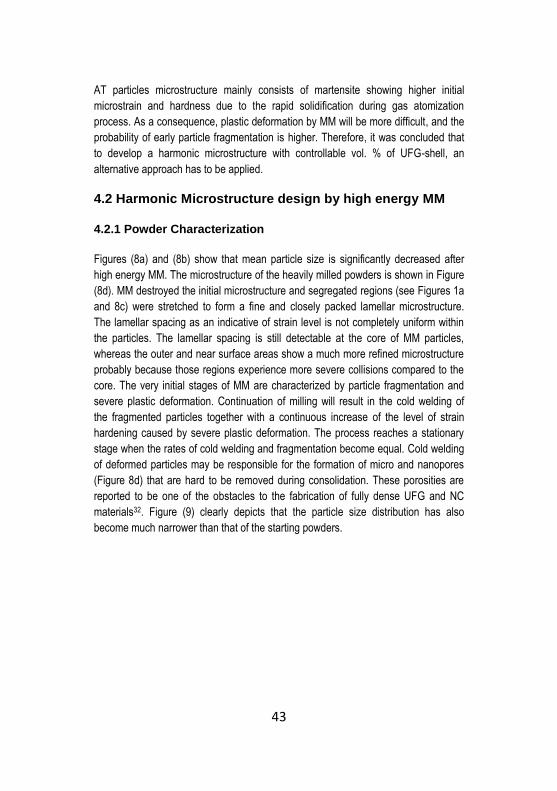
43
AT particles microstructure mainly consists of martensite showing higher initial
microstrain and hardness due to the rapid solidification during gas atomization
process. As a consequence, plastic deformation by MM will be more difficult, and the
probability of early particle fragmentation is higher. Therefore, it was concluded that
to develop a harmonic microstructure with controllable vol. % of UFG-shell, an
alternative approach has to be applied.
4.2 Harmonic Microstructure design by high energy MM
4.2.1 Powder Characterization
Figures (8a) and (8b) show that mean particle size is significantly decreased after
high energy MM. The microstructure of the heavily milled powders is shown in Figure
(8d). MM destroyed the initial microstructure and segregated regions (see Figures 1a
and 8c) were stretched to form a fine and closely packed lamellar microstructure.
The lamellar spacing as an indicative of strain level is not completely uniform within
the particles. The lamellar spacing is still detectable at the core of MM particles,
whereas the outer and near surface areas show a much more refined microstructure
probably because those regions experience more severe collisions compared to the
core. The very initial stages of MM are characterized by particle fragmentation and
severe plastic deformation. Continuation of milling will result in the cold welding of
the fragmented particles together with a continuous increase of the level of strain
hardening caused by severe plastic deformation. The process reaches a stationary
stage when the rates of cold welding and fragmentation become equal. Cold welding
of deformed particles may be responsible for the formation of micro and nanopores
(Figure 8d) that are hard to be removed during consolidation. These porosities are
reported to be one of the obstacles to the fabrication of fully dense UFG and NC
materials32. Figure (9) clearly depicts that the particle size distribution has also
become much narrower than that of the starting powders.

44
Figure IV-8. Morphology of a) gas atomized, b) mechanically milled powders (200min, BPR:
10:1.5 (g/g)), microstructures of c) gas atomized and d) mechanically milled powders. (SEM,
nital 5%)
Figure IV-9. particle size distribution of AT and MM H13
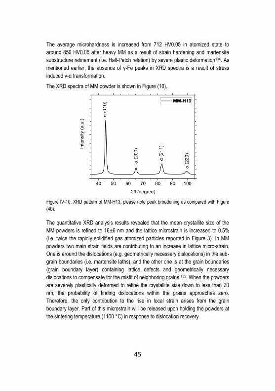
45
The average microhardness is increased from 712 HV0.05 in atomized state to
around 850 HV0.05 after heavy MM as a result of strain hardening and martensite
substructure refinement (i.e. Hall-Petch relation) by severe plastic deformation134. As
mentioned earlier, the absence of γ-Fe peaks in XRD spectra is a result of stress
induced γ-α transformation.
The XRD spectra of MM powder is shown in Figure (10).
Figure IV-10. XRD pattern of MM-H13, please note peak broadening as compared with Figure
(4b).
The quantitative XRD analysis results revealed that the mean crystallite size of the
MM powders is refined to 16±6 nm and the lattice microstrain is increased to 0.5%
(i.e. twice the rapidly solidified gas atomized particles reported in Figure 3). In MM
powders two main strain fields are contributing to an increase in lattice micro-strain.
One is around the dislocations (e.g. geometrically necessary dislocations) in the sub-
grain boundaries (i.e. martensite laths), and the other one is at the grain boundaries
(grain boundary layer) containing lattice defects and geometrically necessary
dislocations to compensate for the misfit of neighboring grains 135. When the powders
are severely plastically deformed to refine the crystallite size down to less than 20
nm, the probability of finding dislocations within the grains approaches zero.
Therefore, the only contribution to the rise in local strain arises from the grain
boundary layer. Part of this microstrain will be released upon holding the powders at
the sintering temperature (1100 °C) in response to dislocation recovery.

46
4.2.2 Spark plasma sintering
Figures (11a & b) depict the sintered microstructures of 0% MM (i.e. AT) and 100%
MM respectively. The 100% MM shows a considerably finer grain size compared to
the gas atomized counterpart, confirming that the fast Spark Plasma Sintering
technique (30 min, 1100°C) allowed to retaining the structural modifications induced
by MM.
Figure IV-11. SEM (BSE) micrographs showing the microstructure of as sintered a) Atomized
and b) 100% UFG-MM, (nital 5%)
The optical micrographs of sintered mixtures are shown in Figure (12). The
micrographs revealed that a threshold of 50 vol. % UFG-MM particles should be
overcome to achieve a 3D interconnected network of UFG-MM surrounding the CG
(AT) particles. Otherwise, the UFG-MM will appear as isolated zones within the CG
matrix. Therefore the 50 to 80% MM samples are referred to as “harmonic
microstructures” while the 20 and 40% MM specimen are considered as “bimodal
grained” microstructures.

47
Figure IV-12. OM micrographs showing the microstructure of as sintered harmonic steels, a)
20%MM, b) 40 % MM, c) 60% MM and d) 80% MM (nital 5%)
The results of intercept length distribution are shown in Figure (13) and the
corresponding average grain size is reported in Table 1. Mean grain diameter (i.e.
prior austenite boundaries) for UFG-MM is 1.4±0.1 m. 25% of grain size population
is smaller than 1.0 μm and 75% of the population is finer than 1.8 μm. Whereas, the
sintered AT particles show a mean grain diameter of 4.2±0.5 m.
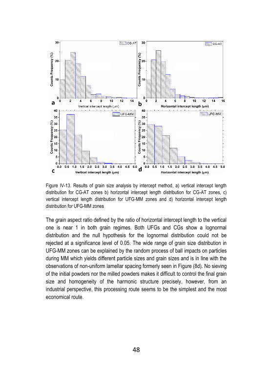
48
Figure IV-13. Results of grain size analysis by intercept method, a) vertical intercept length
distribution for CG-AT zones b) horizontal intercept length distribution for CG-AT zones, c)
vertical intercept length distribution for UFG-MM zones and d) horizontal intercept length
distribution for UFG-MM zones
The grain aspect ratio defined by the ratio of horizontal intercept length to the vertical
one is near 1 in both grain regimes. Both UFGs and CGs show a lognormal
distribution and the null hypothesis for the lognormal distribution could not be
rejected at a significance level of 0.05. The wide range of grain size distribution in
UFG-MM zones can be explained by the random process of ball impacts on particles
during MM which yields different particle sizes and grain sizes and is in line with the
observations of non-uniform lamellar spacing formerly seen in Figure (8d). No sieving
of the initial powders nor the milled powders makes it difficult to control the final grain
size and homogeneity of the harmonic structure precisely, however, from an
industrial perspective, this processing route seems to be the simplest and the most
economical route.

49
Table IV-1 Grain Size ASTM E-112-96 Mean of Vertical and Horizontal Lines
Measuring
Zone
No. of
grains
(mm-2)
Avg.
Grain
area
(μm2)
Avg.
Grain
diameter
(μm)
No.
intercept
(mm-1)
Mean
linear
intercept
line (μm)
ASTM
grain
size
No.
UFG 530000 1.9 1.4 815 1.2 15.8
CG 59000 17 4.2 270 3.7 12.8
The presence of upper bainite and retained austenite (RA) is evidenced mostly in the
UFG zones (see Figure 14).
Figure IV-14. a) SEM (BSE) micrograph of 50% MM microstructure showing bainite in UFG-MM
zones (dark areas) and b) a higher magnification SEM (BSE) micrograph highlighting the
presence of upper bainite and retained austenite
Upon free SPS cooling (i.e. relatively low cooling rates), Austenite (γ) decomposition
into bainite begins at the grain boundaries136. Therefore the higher grain boundary
vol. % in UFG-MM promotes the formation of bainite by increasing the preferential
nucleation sites. As it is highlighted in Figure (14), RA is evidenced in UFGs with a
grain diameter less than 1 μm. It is widely accepted that austenite grain size
reduction increases the stability of austenite, thus hindering the martensitic
transformation137,138.However, due to low vol. % of RA, this phase could not be
quantified by XRD analysis. Since free cooling could not provide a fully martensitic
microstructure, further quench and tempering of the samples will be necessary.

50
4.2.3 Density and hardness of the SPS samples
Figure (15) depicts the density and hardness measurements after SPS. Near full
density samples were produced (see Figure 15a). A gradual decrease in relative
density is observed by increasing the MM vol. %. On one side, MM powders possess
a higher surface energy leading to higher driving force for sintering. However, on the
other hand, this high surface energy is associated with a strong strain hardening of
particles, showing very limited compressibility. As a consequence, neck formation
and extension during SPS will become more difficult, thus hindering the sintering
process.
All blends also show a negative deviation from the linear “rule of mixtures” calculated
by Eq. 1.
𝜌𝐶 = 𝑓 × 𝜌𝑀𝑀 + (1 − 𝑓) × 𝜌𝐴𝑇 (1)
where f is the volume fraction of MM and ρ is the relative density. AT (i.e. 0%MM)
and 100%-MM densities were considered as the reference values.
As it is shown in Figure 15(b), the hardness assumes a general increase by
increasing the MM vol. %. Experimental measurements show a systematic negative
deviation with respect to the theoretical values obtained by the rule of mixtures. This
deviation can be tailored and justified by the same deviation observed in density
measurements.
Figure IV-15. a) Relative density vs. MM volume fraction, b) average Hardness of sintered
specimen vs. MM volume fraction (the straight lines show predicted quantities by the rule of
mixtures)
There exist many experimental evidences that Young’s modulus is negatively
affected by porosity content in polycrystalline materials 5. A widely accepted empirical
relation is proposed by Sanders et al. 139
𝐸 = 𝐸0𝑒𝑥𝑝(−𝑏𝑃) (2)

51
Where E is the reduced modulus, E0 being the fully dense bulk modulus, b is a
parameter equal to 5.03 in a material with the nearly similar Young’s modulus to H13
steel 140 and P is the porosity.
The Vickers indentation impression is a result of elastic-plastic deformation in a fully
dense material. However, in a material containing porosity, pore closure by the
indentation stress also contributes to the indentation impression. It is widely accepted
that by increasing the porosity, hardness decreases. The extent of porosity closure is
proportional to the level of stress induced by the indentation in bulk. By assuming an
elastic deformation, the strain ε (ε11+ ε22+ ε33) is linearly related to the stress σ (σ11+
σ22+ σ33) by the elastic modulus.
𝜎
3𝐸= 𝜀 (3)
Hence it is convenient to roughly conclude that, the observed decrease in hardness
is linearly proportional to a decrease in Young’s modulus of the porous material.
𝐻
𝐻0= 𝑘
𝐸
𝐸0 (4)
where k is a constant and is reported to be very close or equal to 1140. Therefore,
combining (2) and (4), the relation between hardness and porosity is quantified as
follows:
𝐻
𝐻0= 𝑒𝑥𝑝(−5.03𝛥𝑃) (5)
Taking the theoretical hardness calculated by the “rule of mixtures” as the reference
hardness (H0) for each sample, and 𝛥𝑃 as the porosity content difference of the
experimental density measurements with that predicted by the mixtures rule, the
predicted hardness (H) influenced by the porosity, somehow approaches the
experimental results (see Figure 15b).
In addition to the effect of porosity, the non-uniformly distributed MM particles in 40%
MM and 50% MM might account for the high scatters observed in hardness
measurements. It means that whether indenting on a surface with the larger volume
fraction of fine grains than the nominal mixed value, the hardness shifts towards
higher levels and vice versa. However, referring to Eq.6, the radius of the plastic
zone (Cp,) under the Vickers indenter is roughly around 350 μm as depicted in Figure
(16). Looking at the micrographs in Figure (12) and taking the average diameter of
AT and MM powders (i.e. 100 μm and 30 μm respectively) into account, makes it
possible to postulate that the average hardness is statistically accounting for the bulk
(i.e. average microstructure). This is schematically shown in Figure (16).
𝐶𝑝 = √3𝑃
2𝜋𝜎𝑦 (6)

52
Where P is the applied load (100 N, HV10), and σy is the yield stress of the
material141.
Figure IV-16. A schematic of the extent of plastic zone under Vickers indenter, d is the diagonal
of residual impression of indentation which varies in between of 160 to 170 μm in the present
experiment
4.2.4 Grain growth and recrystallization
In MM particles a closed pack lamellar spacing was observed. After SPS, the grains
show a nearly equiaxed morphology that confirms the occurrence of recovery,
recrystallization and limited grain growth during sintering. Both these effects are
responsible for a part of hardness drop after sintering.
It is assumed that the Vickers indentation on powders is not affected by the porosity.
The effect of “sintered sample” porosity (i.e. 1.4%) on the hardness can be
elaborated using Eq. 5. The result suggests that, by neglecting the influence of
porosity, the hardness should be around 810 HV10 in the as-sintered state.
Therefore, the observed difference in hardness (i.e. 810 HV10 vs. 850 HV10 in MM
powder) might be related strain relief and grain growth. XRD analysis results on the
SPS sample confirmed that the mean crystallite size of the sintered 100% UFG-MM
(i.e. 24±4 nm) is increased compared to the as-milled state (i.e. 16±6 nm). Around
40 HV10 drop in hardness is thus a consequence of the limited crystallite grain
growth and follows the widely accepted Hall-Petch relation on the linear
proportionality of strength (hardness) to the reciprocal square route of grain size. The
relation also holds for martensite packets and α-Fe crystallite size in a microstructure
which shows grains with random crystallographic orientations 134.
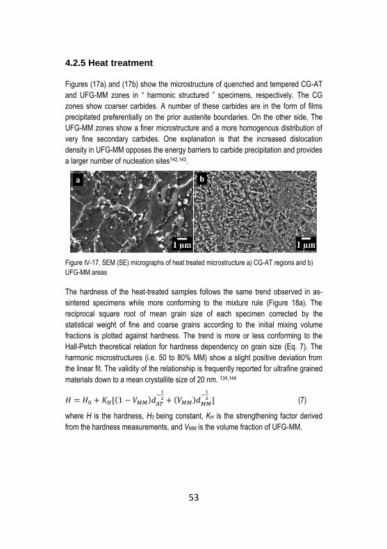
53
4.2.5 Heat treatment
Figures (17a) and (17b) show the microstructure of quenched and tempered CG-AT
and UFG-MM zones in “ harmonic structured ” specimens, respectively. The CG
zones show coarser carbides. A number of these carbides are in the form of films
precipitated preferentially on the prior austenite boundaries. On the other side, The
UFG-MM zones show a finer microstructure and a more homogenous distribution of
very fine secondary carbides. One explanation is that the increased dislocation
density in UFG-MM opposes the energy barriers to carbide precipitation and provides
a larger number of nucleation sites142,143.
Figure IV-17. SEM (SE) micrographs of heat treated microstructure a) CG-AT regions and b)
UFG-MM areas
The hardness of the heat-treated samples follows the same trend observed in as-
sintered specimens while more conforming to the mixture rule (Figure 18a). The
reciprocal square root of mean grain size of each specimen corrected by the
statistical weight of fine and coarse grains according to the initial mixing volume
fractions is plotted against hardness. The trend is more or less conforming to the
Hall-Petch theoretical relation for hardness dependency on grain size (Eq. 7). The
harmonic microstructures (i.e. 50 to 80% MM) show a slight positive deviation from
the linear fit. The validity of the relationship is frequently reported for ultrafine grained
materials down to a mean crystallite size of 20 nm. 134,144
𝐻 = 𝐻0 + 𝐾𝐻[(1 − 𝑉𝑀𝑀)𝑑𝐴𝑇
−1
2 + (𝑉𝑀𝑀)𝑑𝑀𝑀
−1
2 ] (7)
where H is the hardness, H0 being constant, KH is the strengthening factor derived
from the hardness measurements, and VMM is the volume fraction of UFG-MM.

54
Figure IV-18. a) Average hardness vs. the volume fraction of mechanically milled powder b)
Average hardness vs. d (μm)-1/2
4.2.6 Spherical indentation
Figure (19a) plots the reconstructed stress-strain curves from the indentation curves
for 5 samples, namely 0% (i.e. AT), 20%, 50%, 60% and 100% UFG-MM. Figure
(19b) displays the tensile true stress-true strain curves for 0% MM and 100% MM.
Figure IV-19. a) Stress-strain curves reconstructed from spherical indentation curves for the five
samples and b) uniaxial tensile test true stress-true strain curves for 0% MM (AT) and 100%
MM
Table 2 lists the 0.2% proof yield strength of the mono-size grain samples (i.e.
0%MM and 100%MM) together with the yield strength results obtained from spherical
indentation. There is a good agreement between the values obtained from tensile
tests and those of the spherical indentation. Moreover, results show a substantial
increase in the yield strength of the samples by increasing the UFG-MM volume
fraction.
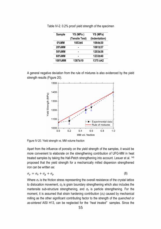
55
Table IV-2. 0.2% proof yield strength of the specimen
Sample YS (MPa )
(Tensile Test)
YS (MPa)
(Indentation)
0%MM 1053±6 1064±30
20%MM - 1081±37
50%MM - 1203±36
60%MM - 1233±40
100%MM 1387±10 1375 ±42
A general negative deviation from the rule of mixtures is also evidenced by the yield
strength results (Figure 20).
Figure IV-20. Yield strength vs. MM volume fraction
Apart from the influence of porosity on the yield strength of the samples, it would be
more convenient to elaborate on the strengthening contribution of UFG-MM in heat
treated samples by taking the Hall-Petch strengthening into account. Lesuer et al. 145
proposed that the yield strength for a mechanically milled dispersion strengthened
iron can be written as:
𝜎𝑦 = 𝜎0 + 𝜎𝑔 + 𝜎𝑝 (8)
Where σo is the friction stress representing the overall resistance of the crystal lattice
to dislocation movement, σg is grain boundary strengthening which also includes the
martensite sub-structure strengthening, and σp is particle strengthening. For the
moment, it is assumed that strain hardening contribution (σd) caused by mechanical
milling as the other significant contributing factor to the strength of the quenched or
as-sintered AISI H13, can be neglected for the “heat treated” samples. Since the

56
samples under investigation are tempered above the secondary hardening peak (i.e.
at 625°C), this assumption is more than plausible. An explanation is that upon the
isothermal holding of AISI H13 at temperatures above the secondary hardening
peak, the dislocation recovery rapidly takes place irrespective of the initial micro-
strain 146. However, the initial dislocation density induced by severe plastic
deformation during MM may increase the number of carbide nucleation sites as
described previously, (see Figure 17) thus decreasing the carbides size and carbides
spacing.
Considering (AT) as the reference specimen, it is possible to rewrite the equation for
the rest of the samples as follows;
𝜎𝑦 − 𝜎𝑦𝐴𝑇 = ∆𝜎𝑦 = ∆𝜎𝑔 + ∆𝜎𝑝 (9)
𝜎𝑔 is the contribution of grain refinement and can be considered analogous to Eq. 7
but with a different value of K’, while 𝜎𝑝 is the contribution of strengthening by
particles and can be written as :
𝜎𝑝 = 𝐾"𝜆𝑠−1/2
(10)
where K” is a constant and λs is the carbide (particle) spacing which is derived from:
𝜆𝑠 = 1.51/2 [(𝜋
4𝑓𝑣)
1
2− 1] 𝑑𝑝 (11)
where fv is the vol. Fraction and dp is the average diameter of carbides. According to
the quantitative image analysis the vol. % of carbides in the samples were estimated
to be around 11.5, the average diameter of carbides (irrespective of the carbide type)
was estimated to be around 90 nm for (AT) and 60 nm for the 100% MM sample. The
value of K” is approximated to be 395 MPa μm1/2 for iron 145. Therefore, it is possible
to estimate the strengthening contribution of fine carbides in harmonic microstructure
and then to evaluate the contribution of grain refinement. Table 3 lists the Δσp for the
samples.

57
Table IV-3. Contribution of particle strengthening to the yield strength of the specimen
considering 0% MM (AT) as the reference, dp is corrected by the statistical weight of fine and
coarse grains according to the initial mixing volume fractions
Sample dp (nm) Δσp
(MPa)
0%MM (AT) 90 0
20%MM 84 32.8
50%MM 75 89.3
60%MM 72 110.4
100%MM 60 210.2
Figure (21) shows the contribution of distinct strengthening mechanisms in harmonic
microstructures.
Figure IV-21. A comparison between experimental yield strength vs. individual strengthening
mechanisms (please note that the fitted line excludes 20% MM data point)
The particle strengthening effect increases by increasing the UFG-MM vol. % as a
result of reduced interparticle (carbide) spacing. Moreover, except from the 20% MM
sample, which did not show a 3D interconnected network of UFG, the grain
refinement strengthening is obeying the Hall-Petch relation. Disregarding the
20%MM sample, the slope (i.e. Hall-Petch slope) of the linear fit of data (dashed
line) becomes around 282 MPa μm1/2, very near to that reported in the literature for
pure iron and steel (i.e. varying between 260 to 310 MPa μm1/2)145,147. A similar trend
is also reported for bimodally grained Iron and SUS 316L steel with harmonic
microstructural design 148,149. It is mandatory to note that in both grain size regimes,

58
the very fine secondary carbides that are not detectable by SEM are not considered
in the above calculations.
4.2.7 Fracture Toughness
The apparent fracture toughness (Kapp) is decreasing by increasing the volume
fraction of harder MM particles (Figure 22). The Ka of AT-H13 is 61.5 MPa m1/2 while
that of 100%MM is 36 MPa m1/2.
Figure IV-22. Fracture toughness (Kapp) of the samples vs. volume fraction of UFG-MM (straight
line shows the predicted values by rule of mixture)
20%MM shows a slightly lower fracture toughness with respect to that predicted by
the “ rule of mixtures.” The sample showed a very similar hardness and yield strength
as compared with the 0%MM (AT) but a lower relative density. The 40%MM shows a
drastic decrease in fracture toughness with highly scattered values. An
inhomogeneous distribution of UFG MM around the CG matrix results in highly
scattered Kapp values for bimodal grain sized materials 100. As mentioned earlier,
40%MM does not show an interconnected network of fine grains due to the
insufficient volume fraction of MM to fully surround AT particles (i.e. forming a 3D
interconnected network). The confinement of isolated coarse grain zones by UFG is
a prerequisite for enhancement of ductility and improved work hardening in bimodal
grained metals by providing the condition for the development of strain gradients
imposed by the microstructure150,151. This can somehow be extended to the
toughness. Therefore, in the absence of an interconnected network, it is probable
that the increased vol. % of hard isolated UFG-MM particles that act as energetically

59
preferential sites for crack propagation is responsible for this drop. Indeed, 50% to
80%MM samples (i.e. harmonic microstructures) and especially 60%MM show a
positive deviation from the rule of mixtures. It was previously stated that there is a
negative deviation from the mixtures rule for hardness and yield strength of these
samples (Figures 18a and 20) attributable, at least in part, to porosity. Knowing that
porosity plays a deleterious effect on the fracture toughness by providing local stress
concentration, a general negative deviation should have been witnessed for the Kapp
values. Moreover, reduced carbide spacing in UFG-MM regions is well-documented
to have a negative influence on toughness by providing a higher number of
energetically preferred sites for crack propagation or in other words, decreasing the
material resistance to crack propagation152. Therefore, despite the validity limits of
the linear “mixtures rule” in predicting a complex fracture behavior, this systematic
deviation might be related to a toughening mechanism induced by the harmonic
microstructure.
The fracture surfaces and the crack propagation paths are depicted in Figures (23 &
24) and (25), respectively. As it is shown in Figure (23a), limited ductile fracture near
the notch region is evidenced for the 0%MM (AT) sample. The rest of the fracture
surface is characterized by interparticle fracture and a few cleavage facets. The
interparticle fracture might be explained by the presence of surface oxides that
hindered a full consolidation (i.e. development of strong metallic bondings between
the particles) despite a nearly complete densification (Figure 15). The surface of the
as-received gas atomized AISI H13 contains a mixed oxide layer on the surface
consisted of a thin and homogeneous iron oxide layer (~7 nm thick) and isolated
oxide particles rich in chromium, manganese, silicon and vanadium 65,66. The
elimination of these oxides requires high vacuum annealing up to 900°C which
introduces a very expensive additional step to the production. Moreover, in spite of a
careful protection (storage in glow box), the oxidation of the surface cannot be easily
avoided while handling these highly reactive powders to the SPS unit.
The interparticle fracture might increase the apparent fracture toughness by
promoting the crack path deflection 44. This type of fracture, as shown in Figure (23d)
is characterized by the presence of localized dimples as an indicative of sintering
neck failure. The 20 and 40%MM samples also show an inter-particle fracture
mechanism (Figures 23b and 23c). The islands of hard UFG-MM particles seem to
anticipate the failure acting as defects inside the AT matrix. The presence of isolated
UFG regions on the fracture path can be appreciated from Figure (25a).

60
Figure IV-23. Fracture surface of a) 0%MM (AT), b) 20%MM (arrows indicating cleavage
facets), c) 40%MM, d) sintering neck failure in 0%MM,e) 60% MM,f) higher magnification of
60%MM (arrows showing delaminations), g) 80%MM and h) 100% MM ( in all micrographs the
dashed lines are representing the boundary of near notch regions and the rest of the fracture
surface, and dashed circles represent the AT particles)
In 50 to 80% UFG-MM samples, the inter-particle fracture can be observed.
Moreover, the fracture surface is characterized by a few cleavage facets and plenty
of very fine dimples (see Figure 24). Cleavage facets are in the range of 5 μm or
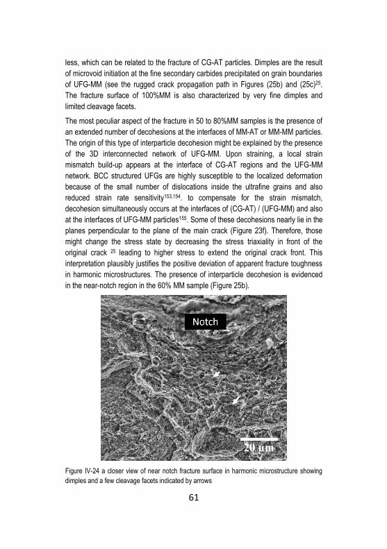
61
less, which can be related to the fracture of CG-AT particles. Dimples are the result
of microvoid initiation at the fine secondary carbides precipitated on grain boundaries
of UFG-MM (see the rugged crack propagation path in Figures (25b) and (25c)25.
The fracture surface of 100%MM is also characterized by very fine dimples and
limited cleavage facets.
The most peculiar aspect of the fracture in 50 to 80%MM samples is the presence of
an extended number of decohesions at the interfaces of MM-AT or MM-MM particles.
The origin of this type of interparticle decohesion might be explained by the presence
of the 3D interconnected network of UFG-MM. Upon straining, a local strain
mismatch build-up appears at the interface of CG-AT regions and the UFG-MM
network. BCC structured UFGs are highly susceptible to the localized deformation
because of the small number of dislocations inside the ultrafine grains and also
reduced strain rate sensitivity153,154. to compensate for the strain mismatch,
decohesion simultaneously occurs at the interfaces of (CG-AT) / (UFG-MM) and also
at the interfaces of UFG-MM particles155. Some of these decohesions nearly lie in the
planes perpendicular to the plane of the main crack (Figure 23f). Therefore, those
might change the stress state by decreasing the stress triaxiality in front of the
original crack 25 leading to higher stress to extend the original crack front. This
interpretation plausibly justifies the positive deviation of apparent fracture toughness
in harmonic microstructures. The presence of interparticle decohesion is evidenced
in the near-notch region in the 60% MM sample (Figure 25b).
Figure IV-24 a closer view of near notch fracture surface in harmonic microstructure showing
dimples and a few cleavage facets indicated by arrows

62
Figure IV-25 crack propagation path, a) 20% MM, b)60% MM, arrow is showing the decohesion
and c) 80% MM ( horizontal arrows are addressing the notch )
From mechanical properties viewpoint, the 60%MM sample (hereinafter referred to
as harmonic sample (HS)) shows the optimum combination of strength and fracture
toughness. The properties of this sample are in good agreement with the
observations of Zheng et al. 148 which reported that optimized mechanical properties
in steel with harmonic microstructure are achieved by the contribution of 50 to 60
vol.% ultrafine grains. It is noteworthy mentioning that the average CG size in their
work was about 2 μm whereas the UFG grains were in the range of 0.7 μm.

63
4.2.8 Thermal Fatigue resistance of the Harmonic Microstructure
The optimized combination of hardness and fracture toughness in the bimodal
harmonic structure are very promising looking at improved resistance to heat
checking. Thermal fatigue resistance of the HS can be of interest in its potential
industrial application where the tool has to show a combination of high toughness
and reasonable hot strength and hardness together with high TF resistance.
4.2.8.1 Microstructure of HS sample used for TF test
The microstructure of the as sintered HS is shown in Figure (26). As stated earlier in
the experimental part, the soft milling of the mixed (UFG-MM and CG-AT) powders
for 1 hour improves the uniformity of the microstructure compared to the sintered
bulk from the mixed powders. The as sintered and heat treated hardness of the
100%MM, HS and 0%MM (AT) disks were the same as the previously tested
samples (Figures 15 and 18) while the standard deviation was considerably reduced
in the case of HS (i.e. 680±8 and 408±2 in as sintered and tempered condition
respectively).
Figure IV-26 Optical micrograph of as-SPS HS produced for TF testing; please note the more
homogeneous AT-AT spacing compared to Figure (12c)
4.2.8.2 TF test results
Figure (27) shows the TF damage of the samples after 200 and 500 cycles. The 0%
MM (AT) (Figures 27 a,d) is clearly showing thicker heat checks which may be held
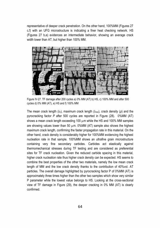
64
representative of deeper crack penetration. On the other hand, 100%MM (Figures 27
c,f) with an UFG microstructure is indicating a finer heat checking network. HS
(Figures 27 b,e) evidences an intermediate behavior, showing an average crack
width lower than AT, but higher than 100% MM.
Figure IV-27. TF damage after 200 cycles a) 0% MM (AT) b) HS, c) 100% MM and after 500
cycles d) 0% MM (AT), e) HS and f) 100% MM
The mean crack length (lm), maximum crack length (lmax), crack density (ρ) and the
pyrocracking factor P after 500 cycles are reported in Figure (28). 0%MM (AT)
shows a mean crack length exceeding 100 m while the HS and 100% MM samples
are showing values lower than 50 m. 0%MM (AT) sample also shows the highest
maximum crack length, confirming the faster propagation rate in this material. On the
other hand, crack density is considerably higher for 100%MM evidencing the highest
nucleation rate in that sample. 100%MM shows an ultrafine grain microstructure
containing very fine secondary carbides. Carbides act elastically against
thermomechanical stresses during TF testing and are considered as preferential
sites for TF crack nucleation. Given the reduced carbide spacing in this material,
higher crack nucleation rate thus higher crack density can be expected. HS seems to
combine the best properties of the other two materials, namely the low mean crack
length of MM and the low crack density thanks to the contribution of 40%vol. AT
particles. The overall damage highlighted by pyrocracking factor P of 0%MM (AT) is
approximately three times higher than the other two samples which show very similar
P parameter while the lowest value belongs to HS. Looking at the cross-sectional
view of TF damage in Figure (29), the deeper cracking in 0% MM (AT) is clearly
confirmed.

65
Figure IV-28 a) Mean crack length, b) Maximum crack length, c) Crack density and d)
pyrocracking factor P measured after 500 TF cycles
Figure IV-29. SEM micrographs of perpendicular plane to damaged surface of a) 0% MM (AT),
b) HS and c) 100% MM

66
The heavy internal oxidation of cracks let to assume the contribution of oxide-
induced propagation mechanisms156. The cracks are very open in this sample
suggesting a considerably high plastic strain. On the other hand, 100%MM sample
shows very short and sharp cracks, whereas HS shows a bimodal cracking which is
responsible for an increase in lm and lmax parameters compared to the 100%MM. The
three-dimensional constraint for the (AT) regions by the harder UFGs is responsible
for the absence of very open cracks in HS.
Figure (30a) depicts the microhardness profile after 500 cycles, normalized by the
initial micro-hardness of each sample, measured in a central position of the TF
specimen. A thermomechanically affected zone exists in all three samples. The
depth of this region is about 2.5 mm for the coarse-grained 0% MM (AT) and around
1 mm for the HS and ultrafine-grained 100% MM. Moreover, the hardness drops to
0.7 initial value near the damaged surface for AT. The situation is different for 100%
MM and HS that show a lower drop in hardness near the “damaged surface.” The
observations in Figure (29) and the microhardness results suggest that 0%MM (AT)
is affected by thermal and plastic strain induced softening 108 more than the two other
samples in the first hundreds of cycles of TF testing. Another important
understanding from the hardness profiles is that the depth of the softening region is
larger than the longest cracks observed in all 3 three samples. This observation
conveys the fact that under the current testing condition (T= 660°C), the resistance
to the TF cracking is mainly controlled by the hot strength and resistance to thermal
softening rather than the toughness of the material 107,157. Resistance to thermal
softening can be directly linked to tempering resistance of the steel. The tempering
curves at 650°C (i.e. near to the TF test temperature) for 0%MM (AT) and 100%MM
are shown in Figure (30b).
Figure IV-30 a) Microhardness profiles (surface to core) after 500 cycles of TF test and b)
tempering resistance curves for 100% MM and 0% MM (AT)

67
After just 1 hour of tempering (Stage 1), the hardness is identical for both samples. A
condition which conveys that hardness drop in 100%MM (HSPS= 755 HV10) occurs at
a higher rate compared to the 0%MM (AT) (HSPS= 636 HV10). For longer isothermal
holding intervals (stage 2), 100%MM shows a higher tempering resistance compared
to the AT counterpart.
The sudden drop in hardness for 100%MM at stage 1 is in agreement with the stress
relieving of the severely deformed UFG-MM microstructure at the tempering
temperature. However, after prolonged soaking, the over-tempering is retarded in
this sample in comparison with the (AT) counterpart. Such behavior is formerly
reported for the AISI H13 tool steel isothermally hold at temperatures above the
secondary hardening peak (i.e. 580°C) 107. At these temperatures, the hardness
drops drastically in the very early stages of isothermal holding irrespective to the
initial microstrain (i.e. dislocation density and other structural defects) due to the fast
dislocation recovery of the substructure interior (i.e. martensite lath)146. By extending
the tempering time, the crucial parameter to determine the tempering resistance is
the precipitated carbides type, morphology, distribution, and size. The finer and more
homogenously dispersed carbides the higher the resistance to thermal softening.
Therefore, the presence of finer secondary carbides in 100%MM corresponds to a
better tempering resistance 158. The contribution of 60 vol. % ultrafine grains forming
an interconnected network in HS thus can be expected to increase the tempering
resistance of this sample as well.
4.2.8.3 TF crack interaction with the harmonic microstructure
The interaction of the strain field in front of a TF crack with the harmonic
microstructure is shown in Figures (31) and (32).
From the metallographic cross-sectional in Figure 29 and theoretical background on
the mechanical properties of the UFG materials discussed earlier, it is convenient to
postulate that most of the TF cracks in HS have been initiated in the UFG zones. The
cracks inside the UFG-MM areas are sharp and propagate along the grain
boundaries. As soon as the crack approach an AT particle, it is arrested (Figure 31a),
and its propagation is retarded by crack-tip blunting as shown in Figure (31b). Crack
tip blunting occurs because of the presence of relatively large grains at the tip of the
propagating crack that accommodate a higher number of emitted dislocations without
hindering the motion of the other dislocations. When more dislocations are emitted
inside the coarse grains (i.e. at higher levels of thermomechanical stresses arising
from heating and cooling cycles), the local strain mismatch between the CG and
UFG will lead to the crack propagation by the decohesion of the UFG/CG interface.
So that crack deflects through these interfaces (see Figures 32a-c) 155. Therefore,
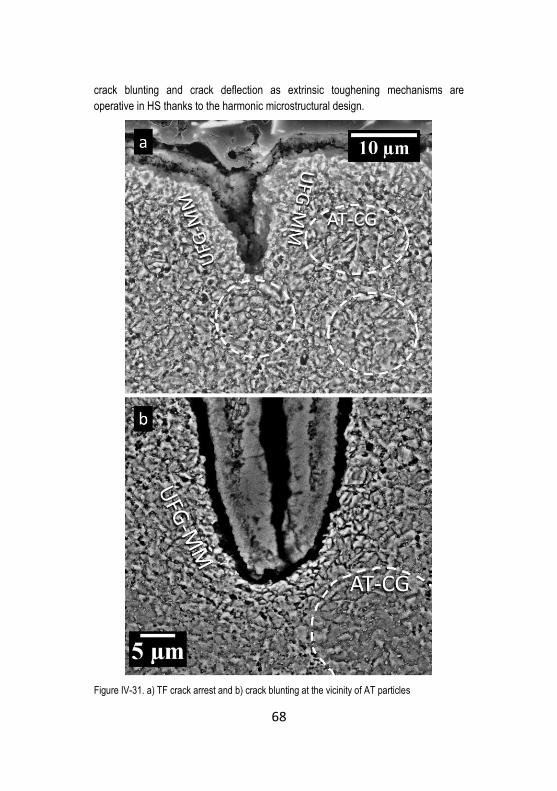
68
crack blunting and crack deflection as extrinsic toughening mechanisms are
operative in HS thanks to the harmonic microstructural design.
Figure IV-31. a) TF crack arrest and b) crack blunting at the vicinity of AT particles

69
Figure IV-32. a) crack deflection along UFG/CG interface, b)closer view of CG AT particle and
c) closer view of UFG-MM zone
To further validate the hypothesis supporting the development of a local strain
mismatch between the UFG and CG zone, the strain hardening rates obtained from
the spherical indentation test for 100%MM, HS and 0%MM is depicted in Figure (33).
Even if these results are obtained at room temperature, those can be used as a
qualitative comparison between strain hardening capacity of the UFG-H13 and CG-
H13.

70
Figure IV-33. Strain hardening rates obtained from spherical indentation test
The pronounced difference between the hardening rates of these two materials up to
~ 15% plastic strain may reinforce the assumption above. It is also evident that the
HS shows a transitional hardening rate expect for the early plastic strain regime
where it shows higher strain hardening than the AT samples. In this strain regime,
due to the presence of a high strength 3D interconnected UFG network it is probable
that the tightly constrained CGs have undergone more intense strain hardening.
Since the UFGs and CGs are not equally easy to deform under the spherical
indentation, the confined coarse grains experience complex strain paths and triaxial
strain components with large plastic strain gradients96. Therefore, according to the
strain-gradient theory 159, this gradient plastic deformation of a length scale of ~10
μm or more (see the spacing between CGs in Figure 26) results in extra strain
hardening due to the storage of large number of geometrically necessary dislocations
near the interfaces of UFGs and CGs which are essentially present to accommodate
the plastic strain gradient. In addition to the direct strengthening effect of the
accumulated dislocations, because of the existence of dislocation density gradients,
these dislocations generate long-range stresses impeding dislocation motion in
regions far from the interface and cause additional hardening 99. This behavior has
been documented in a number of bimodal grain size, harmonic microstructure and
also metals with dispersed nano-domains 99. Upon further straining, as it appears at
an equivalent strain of 15%, where the coarse grains (both in HS and AT samples)
have accumulated a large number of dislocations, all 3 samples show a similar
hardening behavior.

71
Conclusions of part 1
Novel tool steels showing bimodal grain size were fabricated by spark plasma
sintering of as atomized and mechanically milled particles. MM significantly refined
the grain size and introduced a remarkable strain hardening which promotes a
hardness increase in as sintered specimen. A harmonic microstructure, given by a
3D interconnected network of fine-grains surrounding coarse-grained atomized
particles, was achieved by the addition of 50-80% MM powder.
It was shown that in in the case of BCC structured materials, an easier control of
the volume fractions of UFG/CG can be achieved by mixing and/or low energy
mechanical milling of the desired vol. % of the MM-UFG particles with the as-
atomized-CG powders
The hardness of steel increased by increasing the vol. fraction of MM powder.
Despite the bimodal grain size distribution in Harmonic microstructures, both
hardness and yield strength obey the Hall-Petch relationship.
The harmonic microstructure shows enhanced strain hardening compared to the
both mono-size grain (i.e. CG and UFG) under spherical indentation due to the
generation of geometrically necessary dislocation as a result of plastic strain gradient
imposed by the microstructure.
The fracture toughness decreased by increasing the vol. % of MM powder. A
toughening effect was evidenced for the samples essentially showing harmonic
microstructure. Toughening is interpreted to be the result of the deviatory effect of
coarse-grained atomized particles together with energy dissipation by interparticle
fracture at the CG/UFG or UFG/UFG interfaces leading to a local drop of the driving
force for the crack propagation.
Looking at TF test results, the harmonic microstructure combined the beneficial
effects of both of its constituents, i.e., the low nucleation rate of 0%MM (AT)-H13 and
the low propagation rate of 100% MM-H13 and showed the lowest pyrocracking
factor. The harmonic microstructure shows two extrinsic toughening mechanisms,
namely crack blunting and crack deviation along the interfaces between CG and
UFG-MM particles.
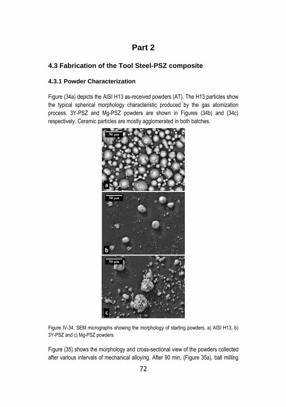
72
Part 2
4.3 Fabrication of the Tool Steel-PSZ composite
4.3.1 Powder Characterization
Figure (34a) depicts the AISI H13 as-received powders (AT). The H13 particles show
the typical spherical morphology characteristic produced by the gas atomization
process. 3Y-PSZ and Mg-PSZ powders are shown in Figures (34b) and (34c)
respectively. Ceramic particles are mostly agglomerated in both batches.
Figure IV-34. SEM micrographs showing the morphology of starting powders, a) AISI H13, b)
3Y-PSZ and c) Mg-PSZ powders
Figure (35) shows the morphology and cross-sectional view of the powders collected
after various intervals of mechanical alloying. After 90 min, (Figure 35a), ball milling

73
destroyed the initial spherical morphology of AISI H13 and flattened the powders.
The particle size is increased compared to the starting powder also due to cold
welding caused by the intense collisions with the balls and the vial. The flat
morphology suggests that the milling process has not reached the stationary state
yet 12. After 200 min the particles show an equiaxed morphology and a quite narrow
size distribution. Moreover, a significant particle size reduction is evidenced (Figure
35b). After 340 min of MA (Figure 35c) no substantial changes regarding particle size
and morphology was observed. Therefore, it is convenient to assume that the steady
state has been reached after 200 min.
Figure IV-35. SEM micrographs of MA (H13+20 vol. % 3Y-PSZ) powders, a) SE image of MA,
90 min, b) SE image of MA, 200 min, c) SE image of MA, 340 min
As it is shown in Figures (36a) and (36b), after 90 min, the surface of the H13
particles is covered with PSZ agglomerates (brighter particles in BSE micrograph),
confirming that a homogenous dispersion of PSZ particles into the matrix is not
achieved. More importantly, the limited local deformability because of the presence
of a hard shell of PSZ suggests that densification will be hindered during SPS. Even
if the driving force for sintering in severe plastically deformed steel particles (see the
steel microstructure in Figure (36b) is increased given the increased dislocation
density and other structural defects, PSZ agglomerates impede the steel particles
contact during sintering thus leading to a weak metallic bonding and consolidation.
Furthermore, the lower specific surface area of the flattened particles partly
counteracts the positive effect of the intense deformation on increasing the driving
force for sintering. It is noteworthy to remark that for all four powders batches, the
vol. % and (dSP/dHP) nearly satisfied the percolation or aggregation of PSZ
particles75,78. Therefore the extension of milling time was necessary to bypass the
aggregation or percolation threshold82. After 200 min (Figure 36c), the distribution of
PSZ inside the matrix became more homogenous. Most particles were occluded in
lamellas of severely deformed steel particles. The number of remained PSZ particles
on the surface is very limited. That is further confirmed by looking at the cross-
sectional view of the polished and etched MA particles in Figure (36d), showing a
severely deformed microstructure characterized by ultrafine lamellas. An unalloyed,
yet severely deformed, isolated H13 can be identified in the same figure. In Figures

74
(36c) and (36d), some micro-pores and nano-cracks appear at the conjunctions of
the cold welded particles. These porosities might be retained after SPS of the MA
powders and are reported to be one of the serious drawbacks to the production of
fully dense nano-sized grain and UFG bulk via PM processing routes 160.
Figure IV-36. BSE image of MA (H13 + 20 vol. % 3Y-PSZ) powders a) after 90 min (powder
surface, brighter particles are Zirconia, b) metallographic cross-section of MA powders, 90 min,
c) BSE image of the powder after 200 min (brighter particles are Zirconia), please follow the
arrow to see micro-pores, and d) metallographic cross-section of MA powders, 200 min
As shown in Figure (37), EDS elemental mapping on the cross section of the
carefully polished MA powders confirmed the achievement of a nearly homogenous
distribution of PSZ in the H13 matrix.
Figure IV-37. EDS elemental mapping on MA powder (20 vol. % Mg-PSZ), the dashed area
shows a region with less concentration of PSZ and arrows are addressing to PSZ particles
(PSZ particles appear brighter in BSE micrograph)

75
Figure (38) shows the particle size distribution of the starting AISI H13 powders and
the mechanically alloyed powders for 200 and 340 min. Looking at the data of 200
min of MA, the size distribution has not been subjected to considerable change after
340 min. Therefore, 200 min was selected as the optimum milling time in this work.
Figure IV-38. Particle size distribution of AT AISI H13 powders, MA (200min) and MA (340min)
The average microhardness of MA powders was higher than 1000 HV0.01 after
200min of milling, however no meaningful distinction between 10 vol. % and 20 vol.
% reinforcement could be appreciated due to the very high scatter of the micro-
hardness measurements which might be related to the very fine size of the powders,
existing un-alloyed H13 areas and presence of microporosity previously shown in
Figure 36. The AT powders microhardness was similar to that reported in section 4.1,
and the average microhardness of mechanically milled H13 powders (MM-H13)
powders was slightly higher than that reported in section 4.2.1 (i.e. 870 HV0.05).
Quantitative analysis results and XRD patterns and are shown in Table 4 and Figure
(39) respectively.
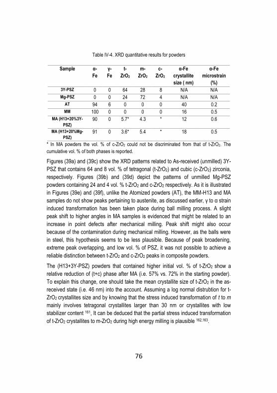
76
Table IV-4. XRD quantitative results for powders
Sample α-
Fe
γ-
Fe
t-
ZrO2
m-
ZrO2
c-
ZrO2
α-Fe
crystallite
size ( nm)
α-Fe
microstrain
(%)
3Y-PSZ 0 0 64 28 8 N/A N/A
Mg-PSZ 0 0 24 72 4 N/A N/A
AT 94 6 0 0 0 40 0.2
MM 100 0 0 0 0 16 0.5
MA (H13+20%3Y-
PSZ)
90 0 5.7* 4.3 * 12 0.6
MA (H13+20%Mg-
PSZ)
91 0 3.6* 5.4 * 18 0.5
* In MA powders the vol. % of c-ZrO2 could not be discriminated from that of t-ZrO2. The
cumulative vol. % of both phases is reported.
Figures (39a) and (39c) show the XRD patterns related to As-received (unmilled) 3Y-
PSZ that contains 64 and 8 vol. % of tetragonal (t-ZrO2) and cubic (c-ZrO2) zirconia,
respectively. Figures (39b) and (39d) depict the patterns of unmilled Mg-PSZ
powders containing 24 and 4 vol. % t-ZrO2 and c-ZrO2 respectively. As it is illustrated
in Figures (39e) and (39f), unlike the Atomized powders (AT), the MM-H13 and MA
samples do not show peaks pertaining to austenite, as discussed earlier, γ to α strain
induced transformation has been taken place during ball milling process. A slight
peak shift to higher angles in MA samples is evidenced that might be related to an
increase in point defects after mechanical milling. Peak shift might also occur
because of the contamination during mechanical milling. However, as the balls were
in steel, this hypothesis seems to be less plausible. Because of peak broadening,
extreme peak overlapping, and low vol. % of PSZ, it was not possible to achieve a
reliable distinction between t-ZrO2 and c-ZrO2 peaks in composite powders.
The (H13+3Y-PSZ) powders that contained higher initial vol. % of t-ZrO2 show a
relative reduction of (t+c) phase after MA (i.e. 57% vs. 72% in the starting powder).
To explain this change, one should take the mean crystallite size of t-ZrO2 in the as-
received state (i.e. 46 nm) into the account. Assuming a log normal distrubtion for t-
ZrO2 crystallites size and by knowing that the stress induced transformation of t to m
mainly involves tetragonal crystallites larger than 30 nm or crystallites with low
stabilizer content 161, It can be deduced that the partial stress induced transformation
of t-ZrO2 crystallites to m-ZrO2 during high energy milling is plausible 162,163.

77
Figure IV-39. XRD patterns of a) 3Y-PSZ (unmilled), b) Mg-PSZ (unmilled), c) elaboration on c-
ZrO2 and t-ZrO2 vol. % in 3Y-PSZ, d) elaboration on c-ZrO2 and t-ZrO2 vol. % in Mg-PSZ, e)
unreinforced powders (i.e. MM and AT) and f) composite (MA) powders milled for 200 min
In the case of coarser Mg-PSZ powders with a large monoclinic phase content (i.e.
72 vol. %) in the as-received state, the vol. % of (t+c) phases is increased after MA
(40% vs. 28% in the starting powder). The mean crystallite size of the t-ZrO2 in as-
received Mg-PSZ powders was calculated to be 16 nm. Therefore, in this system, the
t-m stress induced transformation requires higher energy or longer milling time
compared to the 3Y-PSZ reinforced composite powders 162. On the other hand, even

78
without the addition of a stabilizer, m-ZrO2 can be transformed to cubic and
tetragonal phase by high energy ball milling. This transformation is a consequence of
the significant crystallite size reduction and/or distortion of the monoclinic lattice
because of the high-energy impacts during the ball milling process 164,165. Moreover,
in the presence of a stabilizer (i.e. MgO), the formation of solid solution is favored by
high energy mechanical milling 166. Probably, the same mechanisms are operative in
composite powders containing Mg-PSZ and are responsible for m-t transformation
during MA. It has to be noted that the mean crystallite size of the monoclinic phase in
the unmilled Mg-PSZ powders was about 53 nm while this value reduced to around
21 nm after high energy milling.
PSZ does not show its nominal mixing volume fraction (i.e. 20 vol. %). Lower than
expected zirconia volume fraction can be explained by the absorption contrast effects
in XRD analysis due to the much bigger size of steel particles than that of the
dispersed PSZ 167. This assumption can be justified by looking at the XRD patterns of
powders milled for 90 min (Figure 40) showing that the volume fraction of zirconia in
samples milled for 90 min is overestimated (i.e. 29 vol.%).
Figure IV-40. XRD pattern and vol. % of phases after 90 min MA, please note the overestimated
vol. % of PSZ
Overestimation stems from the accumulation of PSZ on the surface of the powders
with a thickness of about 4 μm (see Figure 36b). Whereas, for the 200 min milled
powders, in which most of the PSZ particles are trapped within the ductile matrix
lamellas (see Figure 36d), the vol. % of PSZ is underestimated.

79
4.3.2 Spark Plasma Sintering
Figure (41a) depicts the lower punch displacement registered during sintering of MA
powders. The curves qualitatively describe the samples densification. Upon applying
the uniaxial pressure, the start of punch displacement nearly appears after 400s
[573°C]. In this stage the steep linear increase is caused by the plastic deformation
of the particles, the harder the particles, the lower the slope. This can be better
appreciated when looking at the displacement, and the first derivative of
displacement curves of softer AT-H13 in Figure (41b). The next stage begins
immediately as the maximum uniaxial pressure (i.e. 60 MPa) is achieved, after
almost 500s and the samples are being heated up to the sintering temperature. This
stage is characterized by a slight decrease in the densification rate due to the ferrite
to austenite transformation in AISI H13 steel (Ac1 ~840°C) 168. The final stage of
consolidation is characterized by the achievement of a plateau for the punch
displacement in Mg-PSZ reinforced composites.
Figure IV-41. Sintering curves of a) composites and b) a comparison of sintering behavior of
AT-H13 and the composites with regard to punch displacement and its first derivative
In the case of the 3Y-PSZ reinforced composites, the curves still maintain a slight
positive slope confirming that complete densification is not achieved. This result can
be explained in the light of the very fine particle size of the starting 3Y-PSZ particles.
Accordingly, the dH13/d3Y-PSZ particle size ratio is much smaller compared to the Mg-
PSZ composite and hard zirconia particles may completely cover the H13 ones, thus
hindering densification and also the diffusion processes promoting sintering. The
incomplete densification of 3Y-PSZ composites will be confirmed by the aid of
density measurements reported in the next section of this work.

80
4.4 Characterization of the tool steel-PSZ composites
4.4.1 Microstructure, hardness, and density
The micrographs of the as-sintered samples are shown in Figure (42).
Figure IV-42. SEM micrographs of as-sintered microstructure of a) AT-H13, b) MM-H13, c) MA(
H13 +10%Mg-PSZ), d) MA( H13 +20% Mg-PSZ) the dashed areas are unalloyed H13, e) MA(
H13 +10%3Y-PSZ), Please note the inter-particle porosities and f) MA( H13 +20% 3Y-PSZ),
Please note the inter-particle porosities
The AT-H13 (Figure 41a) shows an average grain size of nearly 5 μm, the same of
the sintered sample previously described in section 4.2. The MM-H13 sample shows
an ultrafine grained (UFG) microstructure with a mean grain size of 1.3 μm (Figure

81
42b). As it is depicted in (Figures 42c to 42f), composites also evidence an UFG
microstructure. Over 80 vol. % of the bulk demonstrates the achievement of a
successful PSZ dispersion while the rest of the microstructure consists of isolated
unalloyed H13 areas similar to those in the milled powders (Figure 36d). In 3Y-PSZ
reinforced samples, the presence of porosities at the particles interface is evidenced
confirming the former deduction regarding the incomplete densification of this
material. A higher magnification micrograph of the composite microstructure reveals
the presence of fine PSZ particles dispersed in the matrix (Figures 43a and b).
Figure IV-43. a) BSE-SEM micrograph of the 20 vol. % Mg-PSZ reinforced composite, dashed
area is an unalloyed H13, and the brighter spots inside the composite area are PSZ particles
and b) a higher magnification SE micrograph showing a good bonding between dispersed PSZ
particles and the matrix (some PSZ particles are pointed by the arrows)
XRD patterns of the as-SPS samples, shown in Figure (44), confirm the stability of
the t-ZrO2 and c-ZrO2 in the composites thanks to the short time, fast sintering. The t-
m transformation is reported to occur at a critical grain size of t-zirconia 169–171 or due
to the formation of spinel or Mg-rich silicates at the matrix-reinforcement interface
leading to the destabilization of the t-zirconia 172. Present XRD results seem to
exclude both possibilities. The mean crystallite size of α-Fe in AT-H13 is
approximated to be 40 nm while this value for the MM-H13 and the composites is in
the range of 25 nm. For the heavily milled powders recrystallization during sintering
is generally easier than that of as-received powders because of the large excess free
energy. Therefore, in order to preserve the refined microstructure, short time low-
temperature consolidation techniques appear to be necessary. As mentioned earlier,
consolidation by SPS lead to a very limited grain growth in composites and MM-H13.
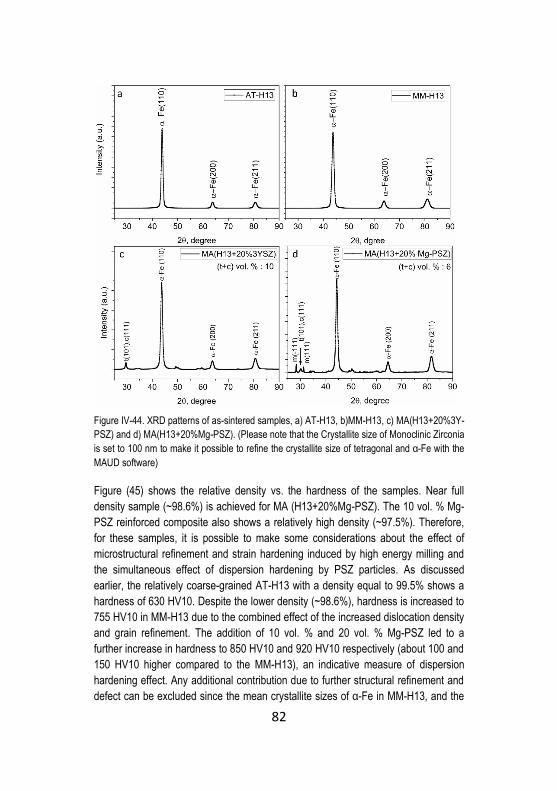
82
Figure IV-44. XRD patterns of as-sintered samples, a) AT-H13, b)MM-H13, c) MA(H13+20%3Y-
PSZ) and d) MA(H13+20%Mg-PSZ). (Please note that the Crystallite size of Monoclinic Zirconia
is set to 100 nm to make it possible to refine the crystallite size of tetragonal and α-Fe with the
MAUD software)
Figure (45) shows the relative density vs. the hardness of the samples. Near full
density sample (~98.6%) is achieved for MA (H13+20%Mg-PSZ). The 10 vol. % Mg-
PSZ reinforced composite also shows a relatively high density (~97.5%). Therefore,
for these samples, it is possible to make some considerations about the effect of
microstructural refinement and strain hardening induced by high energy milling and
the simultaneous effect of dispersion hardening by PSZ particles. As discussed
earlier, the relatively coarse-grained AT-H13 with a density equal to 99.5% shows a
hardness of 630 HV10. Despite the lower density (~98.6%), hardness is increased to
755 HV10 in MM-H13 due to the combined effect of the increased dislocation density
and grain refinement. The addition of 10 vol. % and 20 vol. % Mg-PSZ led to a
further increase in hardness to 850 HV10 and 920 HV10 respectively (about 100 and
150 HV10 higher compared to the MM-H13), an indicative measure of dispersion
hardening effect. Any additional contribution due to further structural refinement and
defect can be excluded since the mean crystallite sizes of α-Fe in MM-H13, and the
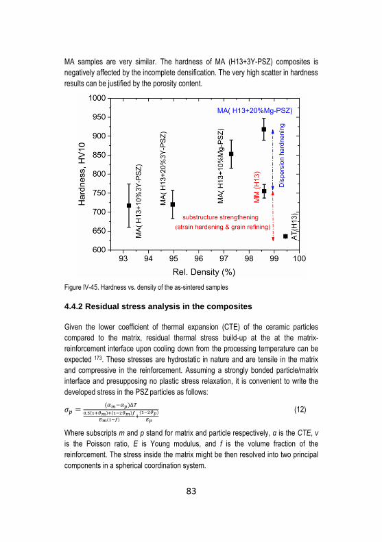
83
MA samples are very similar. The hardness of MA (H13+3Y-PSZ) composites is
negatively affected by the incomplete densification. The very high scatter in hardness
results can be justified by the porosity content.
Figure IV-45. Hardness vs. density of the as-sintered samples
4.4.2 Residual stress analysis in the composites
Given the lower coefficient of thermal expansion (CTE) of the ceramic particles
compared to the matrix, residual thermal stress build-up at the at the matrix-
reinforcement interface upon cooling down from the processing temperature can be
expected 173. These stresses are hydrostatic in nature and are tensile in the matrix
and compressive in the reinforcement. Assuming a strongly bonded particle/matrix
interface and presupposing no plastic stress relaxation, it is convenient to write the
developed stress in the PSZ particles as follows:
𝜎𝑝 =(𝛼𝑚−𝛼𝑝)∆𝑇
0.5(1+𝜗𝑚)+(1−2𝜗𝑚)𝑓
𝐸𝑚(1−𝑓)+
(1−2𝜗𝑝)
𝐸𝑝
(12)
Where subscripts m and p stand for matrix and particle respectively, α is the CTE, ν
is the Poisson ratio, E is Young modulus, and f is the volume fraction of the
reinforcement. The stress inside the matrix might be then resolved into two principal
components in a spherical coordination system.
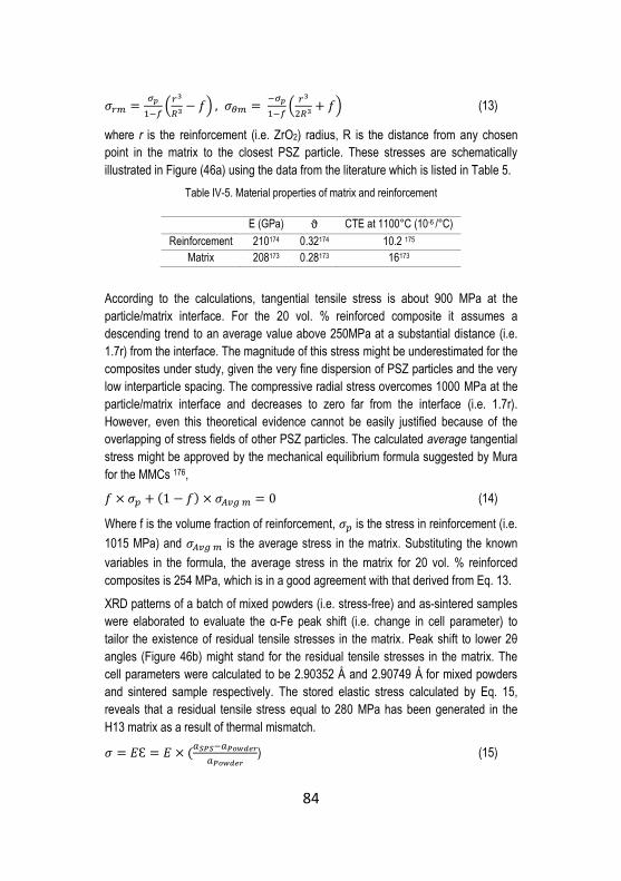
84
𝜎𝑟𝑚 =𝜎𝑝
1−𝑓(
𝑟3
𝑅3 − 𝑓) , 𝜎𝜃𝑚 = −𝜎𝑝
1−𝑓(
𝑟3
2𝑅3 + 𝑓) (13)
where r is the reinforcement (i.e. ZrO2) radius, R is the distance from any chosen
point in the matrix to the closest PSZ particle. These stresses are schematically
illustrated in Figure (46a) using the data from the literature which is listed in Table 5.
Table IV-5. Material properties of matrix and reinforcement
E (GPa) ϑ CTE at 1100°C (10-6 /°C)
Reinforcement 210174 0.32174 10.2 175
Matrix 208173 0.28173 16173
According to the calculations, tangential tensile stress is about 900 MPa at the
particle/matrix interface. For the 20 vol. % reinforced composite it assumes a
descending trend to an average value above 250MPa at a substantial distance (i.e.
1.7r) from the interface. The magnitude of this stress might be underestimated for the
composites under study, given the very fine dispersion of PSZ particles and the very
low interparticle spacing. The compressive radial stress overcomes 1000 MPa at the
particle/matrix interface and decreases to zero far from the interface (i.e. 1.7r).
However, even this theoretical evidence cannot be easily justified because of the
overlapping of stress fields of other PSZ particles. The calculated average tangential
stress might be approved by the mechanical equilibrium formula suggested by Mura
for the MMCs 176,
𝑓 × 𝜎𝑝 + (1 − 𝑓) × 𝜎𝐴𝑣𝑔 𝑚 = 0 (14)
Where f is the volume fraction of reinforcement, 𝜎𝑝 is the stress in reinforcement (i.e.
1015 MPa) and 𝜎𝐴𝑣𝑔 𝑚 is the average stress in the matrix. Substituting the known
variables in the formula, the average stress in the matrix for 20 vol. % reinforced
composites is 254 MPa, which is in a good agreement with that derived from Eq. 13.
XRD patterns of a batch of mixed powders (i.e. stress-free) and as-sintered samples
were elaborated to evaluate the α-Fe peak shift (i.e. change in cell parameter) to
tailor the existence of residual tensile stresses in the matrix. Peak shift to lower 2θ
angles (Figure 46b) might stand for the residual tensile stresses in the matrix. The
cell parameters were calculated to be 2.90352 Å and 2.90749 Å for mixed powders
and sintered sample respectively. The stored elastic stress calculated by Eq. 15,
reveals that a residual tensile stress equal to 280 MPa has been generated in the
H13 matrix as a result of thermal mismatch.
𝜎 = 𝐸Ɛ = 𝐸 × (𝑎𝑆𝑃𝑆−𝑎𝑃𝑜𝑤𝑑𝑒𝑟
𝑎𝑃𝑜𝑤𝑑𝑒𝑟) (15)
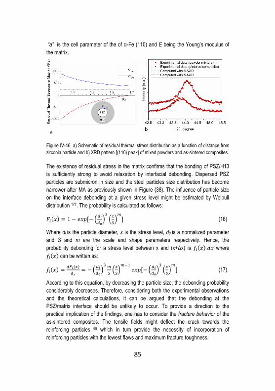
85
“a” is the cell parameter of the of α-Fe (110) and E being the Young’s modulus of
the matrix.
Figure IV-46. a) Schematic of residual thermal stress distribution as a function of distance from
zirconia particle and b) XRD pattern [(110) peak] of mixed powders and as-sintered composites
The existence of residual stress in the matrix confirms that the bonding of PSZ/H13
is sufficiently strong to avoid relaxation by interfacial debonding. Dispersed PSZ
particles are submicron in size and the steel particles size distribution has become
narrower after MA as previously shown in Figure (38). The influence of particle size
on the interface debonding at a given stress level might be estimated by Weibull
distribution 177. The probability is calculated as follows:
𝐹𝑖(𝑥) = 1 − 𝑒𝑥𝑝 [− (𝑑𝑖
𝑑0)
3(
𝑥
𝑆)
𝑚] (16)
Where di is the particle diameter, x is the stress level, d0 is a normalized parameter
and S and m are the scale and shape parameters respectively. Hence, the
probability debonding for a stress level between x and (x+Δx) is 𝑓𝑖(𝑥) 𝑑𝑥 where
𝑓𝑖(𝑥) can be written as:
𝑓𝑖(𝑥) =𝑑𝐹𝑖(𝑥)
𝑑𝑥= − (
𝑑𝑖
𝑑0)
3 𝑚
𝑆(
𝑥
𝑆)
𝑚−1𝑒𝑥𝑝 [− (
𝑑𝑖
𝑑0)
3(
𝑥
𝑆)
𝑚] (17)
According to this equation, by decreasing the particle size, the debonding probability
considerably decreases. Therefore, considering both the experimental observations
and the theoretical calculations, it can be argued that the debonding at the
PSZ/matrix interface should be unlikely to occur. To provide a direction to the
practical implication of the findings, one has to consider the fracture behavior of the
as-sintered composites. The tensile fields might deflect the crack towards the
reinforcing particles 69 which in turn provide the necessity of incorporation of
reinforcing particles with the lowest flaws and maximum fracture toughness.

86
4.4.3 High-temperature chemical stability
The microstructures of the sandwich structure (H13/PSZ/H13) are depicted in
Figures (47a) and (47c).
Figure IV-47. SEM micrographs on the interface of a) H13/3Y-PSZ and b) H13/Mg-PSZ (arrows
are pointing to the cracks)
A seamless interface has formed in H13/3Y-PSZ while Mg-PSZ/H13 interface is
characterized by cracking of the MgPSZ particles at the interface and propagation of
these cracks inside the Mg-PSZ zone. The finer 3Y-PSZ powders can account for the
absence of interface failure and crack extension in H13/3Y-PSZ. The tensile stress
developing in the matrix upon cooling may cause cracking in the adjacent PSZ
particles. Based on energy balance 178, there exist a critical particle size above which
cracking is likely to occur.
𝑑𝑐 > 𝐶/𝜎𝑡 (18)
Where dc is the critical particle size, C is a constant depending on the
matrix/reinforcement pair, and σt (the tensile stress) is calculated by Eq. 13. In a
large number of materials combination where the second phase shows lower CTE,
relatively large particles can satisfy the crack extension condition. Therefore the 3Y-
PSZ particles (d=0.5 μm) may not have satisfied the requirement in Eq.18 while the
coarser as-received Mg-PSZ particles (d=5 μm) satisfied the crack extension
condition. From a mechanical properties point of view, these observations further
confirm the beneficial effect of MA on refining the large Mg-PSZ particles size
resulting in the absence of particle cracking in MA(H13+Mg-PSZ) composites.
The EDS line scan results in H13/Mg-PSZ (Figure 48a) show that the concentration
of Zr, Si, and Mg increases across the interface and remains constant within the PSZ
region. The condition is the same while looking at the line scan analysis of H13/3Y-
PSZ. Under present sintering condition (i.e. 1100°C, 30 min), the consolidated bulks
from as-received powders forming a planar interface apparently show no precipitates

87
or any newly formed phase. The absence of reaction phases is of particular
importance for Mg-PSZ reincforced composite in which silicates have been
previously found to precipitate due to the presence of SiO2 impurity90,179. These
silicates at the interface might impede the t to m transformation in PSZ particle 117.
Figure IV-48. EDS line scan analysis results for the planar interface in a) H13/Mg-PSZ and b)
H13/3Y-PSZ (arrow is pointing at the H13 surface oxides)
However, in 3Y-PSZ reinforced composites produced by mechanical alloying, the
backscattered electron (BSE) micrographs of the as-sintered sample revealed the
formation of small sized reaction layers adjacent to the unalloyed H13 particles
(Figure 49). These areas are characterized by high concentrations of Cr, V and Zr
and the absence of Fe.

88
Figure IV-49. EDS elemental mapping on 3Y-PSZ reinforced composite (arrow is showing the
emerged new phase, and the dashed area is un-alloyed H13)
In Mg-PSZ reinforced composites (Figure 50), EDS mapping did not show any visible reaction zone. In particular, considering Si distribution, it is rather hard to deduce whether silicates have been formed at the matrix-reinforcement interface or not.
Figure IV-50. EDS elemental mapping on Mg-PSZ reinforced composite (brighter spots in BSE
micrographs are PSZ particles)
The coexistence of Cr2O3 and ZrO2 in Steel-Zirconia joint is thermodynamically
plausible at high temperatures (i.e. 1300°C) and an oxygen partial pressure greater
than 5.7 × 10⁻¹⁰ mbar 180 where ZrO2 can be reduced at the expense of oxidation
of Cr. The reduction of Zr does not completely occur, and zirconia will still exist in a
non-stoichiometry state 181:
ZrO2 → ZrO2−X + X/2O2 , 0 ≤ X ≤ 0.02 (19)
However, in a severe plastically deformed matrix with a high density of structural
defects (i.e. dislocations ) that might accelerate the diffusion mechanisms, these
reactions might occur even at a temperature lower than that suggested in the
literature. Moreover, the very fine particle size of 3Y-PSZ leads to a much larger
PSZ-H13 interface area, shorter diffusion path and faster kinetics for the precipitation
reactions of Cr and V oxides compared to the sandwich experiment above. As stated

89
earlier, the peaks pertaining to new phases could not be detected by XRD analysis,
showing only the presence of t-ZrO2 and martensite. This can be explained by the
low amount and very fine distribution of these precipitates. In the case of Mg-PSZ
reinforced composites, the same phenomenon is not observed due to the coarser
size of PSZ particles.
In order to prove the chemical stability of the composites and to validate the above
conclusions, samples were further subjected to long time (i.e. 1 and 2 h) exposure at
the sintering temperature (i.e. 1100° C) under vacuum (5.0 × 10⁻⁷ bar). After two
hours (Figures 51a and 52b) in both Mg-PSZ and 3Y-PSZ reinforced composites,
new phases have emerged. EDS spot analysis results for Mg-PSZ and 3Y-PSZ
reinforced composites are listed in Tables 6 and 7 respectively.
Figure IV-51. BSE micrograph of composite after 2 h holding at 1100°C, a) MA( H13+20% Mg-
PSZ) and b) MA(H13+20% 3Y-PSZ)
Table IV-6. EDS spot analysis on 20 vol. % Mg-PSZ reinforced composite (wt. %)
Zone Fe Zr Cr V Si Mn Mo Mg
1 24.5 14.3 25.1 6.0 4.2 1.7 - 0.5
2 86.8 0.3 0.9 - - - 1.8 -
3 44.0 6.4 4.6 1.0 11.6 5.1 - 2.9
4 11.3 71.4 0.1 0.6 - - - 0.4
Table IV-7. EDS spot analysis on 20 vol. % 3Y-PSZ reinforced composite (wt. %)
Zone Fe Zr Cr V Si Mn Mo Y
1 38.0 8.1 20.7 5.0 1.8 1.2 - -
2 74.2 - 0.3 - - - 1.7 -
3 66.8 10.8 0.5 - 0.2 - 1.4 0.6
4 23.5 52.7 0.3 - 1.7 - 1.0 1.3
Spot 1 in both micrographs is corresponding to a Cr, V rich zone. It appears that the
reaction layer has been formed in the H13-ZrO2 system. These zones might consist

90
of complex oxides of Cr, V, and Zr. Spot 2 in both micrographs is showing H13
matrix in the vicinity of reaction zones which has been depleted of Cr, V, and Mn.
Therefore, it can be postulated that inter-diffusion of several elements has taken
place during high-temperature holding thus resulting in the formation of complex
oxides. In Figure (51a), Spot 3 is characterized by a high concentration of Si, Mn,
and Mg that might represent the precipitation of (Mg, Mn)Si2O4 which was formerly
reported in Steel-Mg-PSZ systems 90,179. In Figure (51b) spot 3 is an MA area which
is depleted of Cr and V. The brightest particles (Spot 4 in Figures 51a and 51b) are
PSZ particles. Further investigations are needed to be performed by the aid of EBSD
analysis on these samples to elaborate more on the composition and structure of the
newly formed phases.
The conclusion is mostly intended to highlight the efficiency of short time sintering of
SPS that has not allowed the formation of excessive reaction zones. For the as-
sintered 3Y-PSZ reinforced composite, the width of the reaction layers was limited to
several microns. The presence of small and limited reaction zone can be beneficial in
view of the strengthening of reinforcement and matrix interface which in turn results
in more efficient load transfer from the matrix to the reinforcement 182. The absence
of reaction zones in the as-sintered Mg-PSZ reinforced composites can be related to
the coarser particle size corresponding to lower surface energy and lower kinetics of
Mg-PSZ/Steel interfacial reaction. However, since in the present study the properties
of the composites with the incorporation of fine sized Mg-PSZ particles is not
elaborated, a definitive interpretation of the dependence of the interfacial reaction
kinetics on the reinforcement particle size cannot be made.
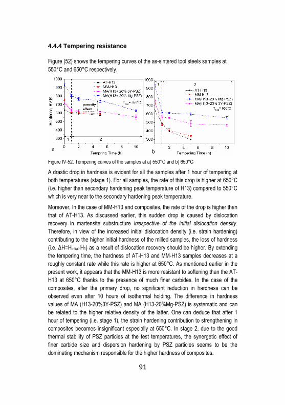
91
4.4.4 Tempering resistance
Figure (52) shows the tempering curves of the as-sintered tool steels samples at
550°C and 650°C respectively.
Figure IV-52. Tempering curves of the samples at a) 550°C and b) 650°C
A drastic drop in hardness is evident for all the samples after 1 hour of tempering at
both temperatures (stage 1). For all samples, the rate of this drop is higher at 650°C
(i.e. higher than secondary hardening peak temperature of H13) compared to 550°C
which is very near to the secondary hardening peak temperature.
Moreover, In the case of MM-H13 and composites, the rate of the drop is higher than
that of AT-H13. As discussed earlier, this sudden drop is caused by dislocation
recovery in martensite substructure irrespective of the initial dislocation density.
Therefore, in view of the increased initial dislocation density (i.e. strain hardening)
contributing to the higher initial hardness of the milled samples, the loss of hardness
(i.e. ΔH=Hintial-H1) as a result of dislocation recovery should be higher. By extending
the tempering time, the hardness of AT-H13 and MM-H13 samples decreases at a
roughly constant rate while this rate is higher at 650°C. As mentioned earlier in the
present work, it appears that the MM-H13 is more resistant to softening than the AT-
H13 at 650°C thanks to the presence of much finer carbides. In the case of the
composites, after the primary drop, no significant reduction in hardness can be
observed even after 10 hours of isothermal holding. The difference in hardness
values of MA (H13-20%3Y-PSZ) and MA (H13-20%Mg-PSZ) is systematic and can
be related to the higher relative density of the latter. One can deduce that after 1
hour of tempering (i.e. stage 1), the strain hardening contribution to strengthening in
composites becomes insignificant especially at 650°C. In stage 2, due to the good
thermal stability of PSZ particles at the test temperatures, the synergetic effect of
finer carbide size and dispersion hardening by PSZ particles seems to be the
dominating mechanism responsible for the higher hardness of composites.
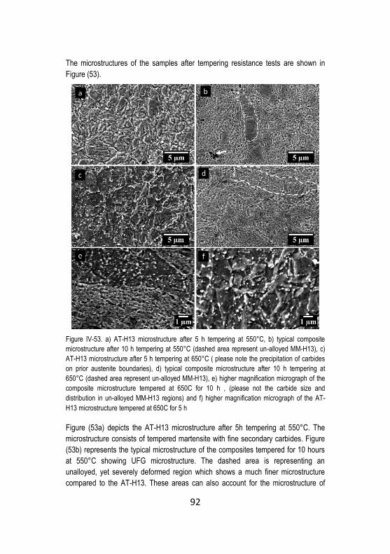
92
The microstructures of the samples after tempering resistance tests are shown in
Figure (53).
Figure IV-53. a) AT-H13 microstructure after 5 h tempering at 550°C, b) typical composite
microstructure after 10 h tempering at 550°C (dashed area represent un-alloyed MM-H13), c)
AT-H13 microstructure after 5 h tempering at 650°C ( please note the precipitation of carbides
on prior austenite boundaries), d) typical composite microstructure after 10 h tempering at
650°C (dashed area represent un-alloyed MM-H13), e) higher magnification micrograph of the
composite microstructure tempered at 650C for 10 h , (please not the carbide size and
distribution in un-alloyed MM-H13 regions) and f) higher magnification micrograph of the AT-
H13 microstructure tempered at 650C for 5 h
Figure (53a) depicts the AT-H13 microstructure after 5h tempering at 550°C. The
microstructure consists of tempered martensite with fine secondary carbides. Figure
(53b) represents the typical microstructure of the composites tempered for 10 hours
at 550°C showing UFG microstructure. The dashed area is representing an
unalloyed, yet severely deformed region which shows a much finer microstructure
compared to the AT-H13. These areas can also account for the microstructure of

93
MM-H13. Figure (53c) depicts the AT-H13 microstructure showing a larger number of
secondary carbides precipitated (carbide films) on the prior austenite grain
boundaries. Figure (53d) shows the composite tempered for 10 h at 650°C. The UFG
microstructure contains very fine and homogeneously distributed carbides. Looking
at the dashed area (representing the unalloyed H13) in the same figure, it can be
appreciated that the carbide size is much finer than that of AT-H13 that precipitates
are more homogenously distributed. The higher magnification micrographs in Figures
(53e) and (53f) better highlight the size and distribution of secondary carbides inside
the unalloyed H13 regions in composite (i.e. MM-H13) and the AT-H13 respectively.
It can be concluded that the very fine PSZ particles embedded in the ultra-fine
grained matrix seem to be stable to the temperature exposure and dispersion
hardening effect holds even for longer tempering times2.
4.4.5 Hot Compression
The hot compression test results of 20 vol. % reinforced composites and the
unreinforced samples are listed in Table 8. AT-H13 shows the lowest yield strength
in all testing temperatures. The yield strength of the UFG MM-H13 is around 1.3
times more than the AT-H13 thanks to the strain hardening and substructure
strengthening induced by mechanical milling. The yield strength is significantly
improved by the incorporation of PSZ particles especially at higher temperatures
indicative of the dispersion strengthening effect of the PSZ reinforcement. Again, the
lower relative density of MA (H13+20% 3Y-PSZ) might be responsible for the lower
compressive yield strength of the composite compared to the Mg-PSZ reinforced
counterpart.
Table IV-8. 0.2% offset compressive yield strength of the samples
Temperature (°C) AT-H13 MM-H13 MA
(H13-3Y-PSZ)`
MA
(H13-Mg-PSZ)
20 1810 MPa 2130 MPa 2420 MPa 2650 MPa
450 720 MPa 1130 MPa 1920 MPa 2070 MPa
650 480 MPa 795 MPa 920 MPa 1270 MPa
It is noteworthy to mention that, the room temperature test results are in line with the
approximated yield strength calculated from the hardness measurements (Table 9).
The conversion of the Vickers hardness to Yield strength is done using the following
relation for the “severely cold worked steel” 183.
𝜎𝑦(𝐺𝑃𝑎) = 0.003𝐻𝑉 (20)

94
Dealing with particle reinforced MMCs, in a hardness test, deformation is localized,
and particles undergo compressive stresses with a high degree of stress triaxiality184.
As a result, particle fracture during indentation is suppressed, and HPs contribute to
the “strengthening.” Therefore, the compressive yield strength might show a
meaningful correlation with the hardness.
Table IV-9. Estimated room temperature yield strength using the hardness results
Temperature (°C) AT-H13 MM-H13 MA
(H13-3Y-PSZ)`
MA
(H13-Mg-PSZ)
20 1910 MPa 2250 MPa 2160 MPa* 2760 MPa
*relative density in this sample is 95%
The stress-strain curves at room temperature and 650°C tests are shown in Figures
(54a) and (54b) respectively. Due to approaching the force limit of the equipment (i.e.
20 KN, corresponding to a stress equal to about 2800 MPa) at the initial stages of
strain hardening, it was not possible to complete the room temperature compression
test to 6% strain for the composites.
Figure IV-54. Stress-strain curves of samples tested at a) room temperature (20 °C) and b)
650°C
Figure (55) shows the strain hardening rate curves and strain hardening exponents
(n) of the samples at 650°C and 450°C under quasi-static compressive deformation.
The matrix strain hardening can be described by the dislocation movement and
accumulation of dislocations. The general lower hardening rates at 650°C compared
to 450°C is due to the loss of strength by increasing the temperature that counteracts
the strain hardening by compression. The lower strain hardening rate of AT-H13
compared to MM-H13 can be attributed to its larger grain size and lower density of
structural defects (i.e. dislocations) in the as-sintered condition. As it can be
appreciated from the graphs, the “apparent strain hardening rate” at the initial stages
of plastic deformation is highest for the Mg-PSZ reinforced sample due to the

95
strengthening effect of Mg-PSZ particles which is in agreement with the observations
of Martin et al. 185 For TRIP steel-Mg-PSZ composites. This effect is less pronounced
in 3Y-PSZ reinforced composite which is probably due to the higher amount of
porosity in the composite material.
Figure IV-55. a) Strain hardening rate of the samples at 650°C, b) strain hardening rate of the
samples at 450°C , c) hardening exponent (n) during plastic deformation for matrix material and
Mg-PSZ reinforced composite at 650°C and d) hardening exponent (n) during plastic
deformation for matrix material and Mg-PSZ reinforced composite at 450°C
From around 3% up to 6% plastic strain at both temperatures, it is evident that the
hardening rate and hardening exponent drop to lower values compared to the matrix
material (i.e. MM-H13). The decline in hardening rate might have caused by
debonding and fracture of PSZ or the reaction products179,186,187. The increased work
hardening rate of the MMCs can be ascribed to the geometric constraints generated
by the presence of HPs impeding the dislocations movement, and local increase of
HPs volume fraction under loading and accordingly the parallel decrease in volume
fraction of the matrix which is being deformed. Moreover, PSZ particles may undergo
t-m stress induced transformation accompanied by volume expansion. The
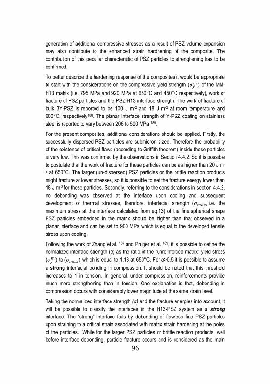
96
generation of additional compressive stresses as a result of PSZ volume expansion
may also contribute to the enhanced strain hardnening of the composite. The
contribution of this peculiar characteristic of PSZ particles to strenghening has to be
confirmed.
To better describe the hardening response of the composites it would be appropriate
to start with the considerations on the compressive yield strength (𝜎𝑦𝑚) of the MM-
H13 matrix (i.e. 795 MPa and 920 MPa at 650°C and 450°C respectively), work of
fracture of PSZ particles and the PSZ-H13 interface strength. The work of fracture of
bulk 3Y-PSZ is reported to be 100 J m-2 and 18 J m-2 at room temperature and
600°C, respectively188. The planar Interface strength of Y-PSZ coating on stainless
steel is reported to vary between 206 to 500 MPa 189.
For the present composites, additional considerations should be applied. Firstly, the
successfully dispersed PSZ particles are submicron sized. Therefore the probability
of the existence of critical flaws (according to Griffith theorem) inside these particles
is very low. This was confirmed by the observations in Section 4.4.2. So it is possible
to postulate that the work of fracture for these particles can be as higher than 20 J m-
2 at 650°C. The larger (un-dispersed) PSZ particles or the brittle reaction products
might fracture at lower stresses, so it is possible to set the fracture energy lower than
18 J m-2 for these particles. Secondly, referring to the considerations in section 4.4.2,
no debonding was observed at the interface upon cooling and subsequent
development of thermal stresses, therefore, interfacial strength (𝜎𝑚𝑎𝑥, i.e. the
maximum stress at the interface calculated from eq.13) of the fine spherical shape
PSZ particles embedded in the matrix should be higher than that observed in a
planar interface and can be set to 900 MPa which is equal to the developed tensile
stress upon cooling.
Following the work of Zhang et al. 187 and Pruger et al. 189, it is possible to define the
normalized interface strength (α) as the ratio of the “unreinforced matrix” yield stress
(𝜎𝑦𝑚) to (𝜎𝑚𝑎𝑥) which is equal to 1.13 at 650°C. For α>0.5 it is possible to assume
a strong interfacial bonding in compression. It should be noted that this threshold
increases to 1 in tension. In general, under compression, reinforcements provide
much more strengthening than in tension. One explanation is that, debonding in
compression occurs with considerably lower magnitude at the same strain level.
Taking the normalized interface strength (α) and the fracture energies into account, it
will be possible to classify the interfaces in the H13-PSZ system as a strong
interface. The “strong” interface fails by debonding of flawless fine PSZ particles
upon straining to a critical strain associated with matrix strain hardening at the poles
of the particles. While for the larger PSZ particles or brittle reaction products, well
before interface debonding, particle fracture occurs and is considered as the main
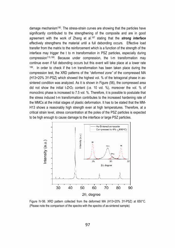
97
damage mechanism190. The stress-strain curves are showing that the particles have
significantly contributed to the strengthening of the composite and are in good
agreement with the work of Zhang et al.187 stating that the strong interface
effectively strengthens the material until a full debonding occurs. Effective load
transfer from the matrix to the reinforcement which is a function of the strength of the
interface may trigger the t to m transformation in PSZ particles, especially during
compression115,189. Because under compression, the t-m transformation may
continue even if full debonding occurs but this event will take place at a lower rate 189. In order to check if the t-m transformation has been taken place during the
compression test, the XRD patterns of the “deformed zone” of the compressed MA
(H13+20% 3Y-PSZ) which showed the highest vol. % of the tetragonal phase in as-
sintered condition was analyzed. As it is shown in Figure (56), the compressed area
did not show the initial t-ZrO2 content (i.e. 10 vol. %), moreover the vol. % of
monoclinic phase is increased to 7.5 vol. %. Therefore, it is possible to postulate that
the stress induced t-m transformation contributes to the increased hardening rate of
the MMCs at the initial stages of plastic deformation. It has to be stated that the MM-
H13 shows a reasonably high strength even at high temperatures. Therefore, at a
critical strain level, stress concentration at the poles of the PSZ particles is expected
to be high enough to cause damage to the interface or large PSZ particles.
Figure IV-56. XRD pattern collected from the deformed MA (H13+20% 3Y-PSZ) at 650°C.
(Please note the comparison of the spectra with the spectra of as-sintered sample)

98
Unfortunately, reliable results could not be obtained from the XRD analysis on Mg-
PSZ reinforced composites mainly because of low vol. % of t-ZrO2 in as sintered
samples and difficulties in sample preparation.
Figure (57a) is showing the un-deformed surface of the Mg-PSZ reinforced
composite. Figure (57b-c) are showing the deformed surface of Mg-PSZ reinforced
composite subjected to hot compression at 650°C and Figure (57d) is showing the
debonding of a fine PSZ particle (spot 1). The figure also highlights the fracture of a
reaction product which is rich in Si, Mn, and Zr, (spot 2). The EDS spot analysis
results of the particle are listed in Table 10.
Figure IV-57. Deformed surface of the samples at 650°C, a) OM micrograph of the un-deformed
composite (white isolated regions are un-alloyed H13), b) OM micrograph of the deformed
composite, please see the plastic deformation of unalloyed H13, arrows indicating compression
direction, c) SEM micrograph of the deformed surface, arrows indicating compression direction
and d) higher magnification SEM micrograph showing particle debonding (1) and particle
fracture (2)
Table IV-10. EDS spot analysis results on particles (1) and (2) in Figure (57d), wt. %
spot Fe Zr Cr V Si Mn Mo Mg
1 52 35 5 1.4 1 0.4 - 0.3
2 62 25 7 1 5 1.7 1 -

99
It appears that the transformation of t to m can be successfully exploited to
strengthen the H13 matrix.
Application of higher heating rates for the SPS may completely exclude the formation
of thermodynamically plausible reaction products. On one side, elimination of the
reaction layers can be beneficial since these products are generally brittle and
detrimental to strength. Moreover, their emergence is accompanied by t-ZrO2
destabilization. On the other hand, extremely thin and limited reaction layers can
promote the interfacial strength allowing more efficient load transfer. Therefore,
elaboration on the extent and composition of silicates and possibly spinel phases are
of the future work of the author.
4.4.6 Fracture Toughness
The hardness vs. fracture toughness of heat-treated composites together with the
results of 20 vol. % TiC reinforced H13 are shown in Figure 58. The TiC reinforced
composite showed a relative density equal to ~ 98.5 %. In comparison with the data
of unreinforced MM-H13 (i.e. ~420 HV10 and Kapp=36 MPa m1/2) a general decrease
in fracture toughness and a general increase in hardness can be appreciated. The
apparent fracture toughness of Mg-PSZ reinforced composite is the highest among
all 3 samples, the hardness being practically the same of TiC reinforced composite.
The MA (H13+ 20%3Y-PSZ) is showing the lowest fracture toughness and also a
very low hardness compared to the other counterparts, due to the high inter-particle
porosity.
Figure IV-58. Hardness vs. apparent fracture toughness of the composites

100
Figure (59a) depicts the fracture surface of TiC reinforced composite. The surface
seems to exclude any ductility contribution to fracture. The interparticle fracture
(dashed area), and very fine and limited cleavage facets probably belong to the
unalloyed H13 zones can be seen in Figure (59d). The higher magnification
micrograph in Figure (59d) reveals the mechanism of void initiation by matrix/TiC
decohesion. There also exists a few number of fractured TiC particles on the fracture
surface (see Figure 60). The EDS area analysis as a semi-quantitative analysis
revealed the presence of 15±1.5 wt. % Ti on the fracture surfaces corresponding to
around 25 vol. % of TiC which is 1.25 times higher than the initial mixing volume. The
fracture surface analysis suggests that the crack has propagated mainly through the
reinforcement or by decohesion at reinforcement/particle interface. The fracture
surface of Mg-PSZ reinforced composite shown in Figures (59b) and (59d) features
some decohesion between the unalloyed H13 regions and the composite parts. The
higher magnification micrograph (Figure 59f) reveals the occurrence of the
particle/matrix decohesion together with the presence of clusters of PSZ and also
regions characterized by fractured “reaction products.” The vol. % of Mg-PSZ on the
fracture surfaces is approximately 1.1 times higher than the nominal mixing volume.
In these composites, the absence of extensive interparticle fracture confirms
successful consolidation and development of strong metallic bonding. Therefore,
upon the increase of stress concentration at the poles of the particles, the reinforcing
particles fractured or debonded and crack propagated in the most energetically
preferential path. This type of fracture behavior was formerly evidenced for the
MMCs processed with severe plastic deformation showing a very homogeneous
distribution of fine HPs 87. Generation of tensile fields (as a result of the thermal
mismatch between matrix and reinforcement) near the particle/matrix interface, might
also be effective in view of crack deviation towards the particle/matrix interface 18.
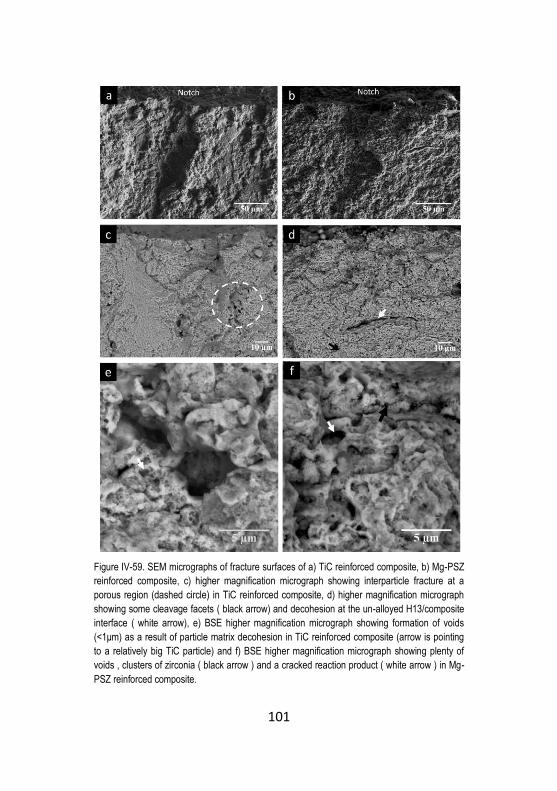
101
Figure IV-59. SEM micrographs of fracture surfaces of a) TiC reinforced composite, b) Mg-PSZ
reinforced composite, c) higher magnification micrograph showing interparticle fracture at a
porous region (dashed circle) in TiC reinforced composite, d) higher magnification micrograph
showing some cleavage facets ( black arrow) and decohesion at the un-alloyed H13/composite
interface ( white arrow), e) BSE higher magnification micrograph showing formation of voids
(<1μm) as a result of particle matrix decohesion in TiC reinforced composite (arrow is pointing
to a relatively big TiC particle) and f) BSE higher magnification micrograph showing plenty of
voids , clusters of zirconia ( black arrow ) and a cracked reaction product ( white arrow ) in Mg-
PSZ reinforced composite.
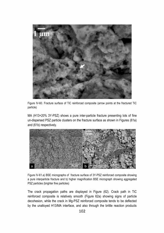
102
Figure IV-60. Fracture surface of TiC reinforced composite (arrow points at the fractured TiC
particle)
MA (H13+20% 3Y-PSZ) shows a pure inter-particle fracture presenting lots of fine
un-dispersed PSZ particle clusters on the fracture surface as shown in Figures (61a)
and (61b) respectively.
Figure IV-61.a) BSE micrographs of fracture surface of 3Y-PSZ reinforced composite showing
a pure interparticle fracture and b) higher magnification BSE micrograph showing aggregated
PSZ particles (brighter fine particles)
The crack propagation paths are displayed in Figure (62). Crack path in TiC
reinforced composite is relatively smooth (Figure 62a) showing signs of particle
decohesion, while the crack in Mg-PSZ reinforced composite tends to be deflected
by the unalloyed H13/MA interface, and also through the brittle reaction products
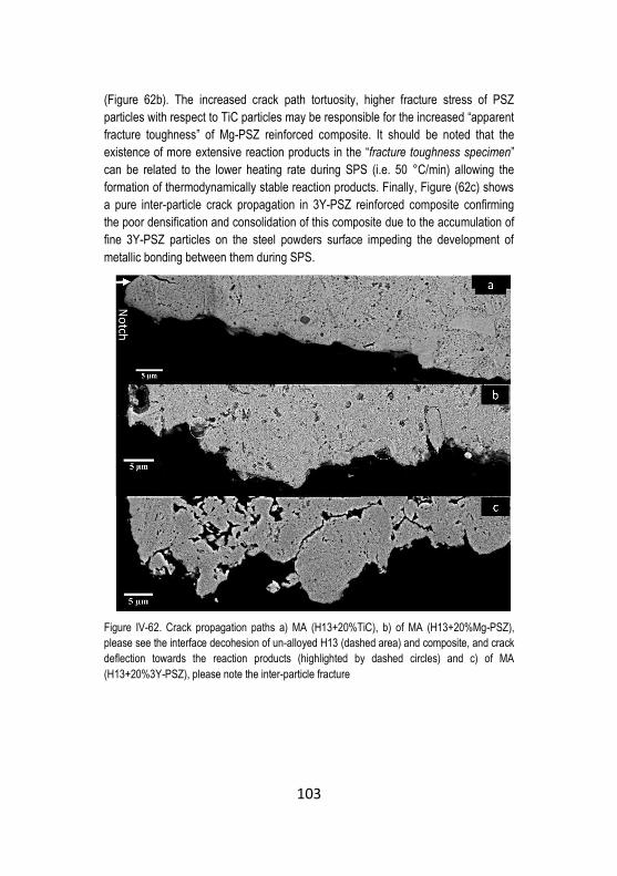
103
(Figure 62b). The increased crack path tortuosity, higher fracture stress of PSZ
particles with respect to TiC particles may be responsible for the increased “apparent
fracture toughness” of Mg-PSZ reinforced composite. It should be noted that the
existence of more extensive reaction products in the “fracture toughness specimen”
can be related to the lower heating rate during SPS (i.e. 50 °C/min) allowing the
formation of thermodynamically stable reaction products. Finally, Figure (62c) shows
a pure inter-particle crack propagation in 3Y-PSZ reinforced composite confirming
the poor densification and consolidation of this composite due to the accumulation of
fine 3Y-PSZ particles on the steel powders surface impeding the development of
metallic bonding between them during SPS.
Figure IV-62. Crack propagation paths a) MA (H13+20%TiC), b) of MA (H13+20%Mg-PSZ),
please see the interface decohesion of un-alloyed H13 (dashed area) and composite, and crack
deflection towards the reaction products (highlighted by dashed circles) and c) of MA
(H13+20%3Y-PSZ), please note the inter-particle fracture

104
Conclusions of part 2
Near full density composites were successfully produced by optimized
Mechanical Alloying and fast Spark Plasma Sintering.
A too fine particle size negatively affects the densification of MA (H13+3Y-PSZ)
composites due to overcoming the percolation threshold, impeding the direct H13-
H13 contact during sintering. Therefore, in order to achieve a more homogenous
distribution of PSZ particles into the matrix, the initial particle size of the PSZ (or the
particle size ratio dH13/dPSZ) has to be properly selected. The practical interpretation
of the present results can be summarized as follows. MA can be considered as an
efficient method to refine the size of relatively large HPs (d ~ 5 μm, dmatrix/dhp = 4)
down to less than 1 μm and provide a homogenous distribution of these particles
inside the matrix. A condition which guarantees the achievement of near fully dense
composite reinforced with high strength flawless fine HPs. In view of the present
results, this combination cannot be achieved using 10 and 20 vol. % of ultrafine HPs
as the starting powder (d ~ 0.5 μm, dmatrix/dhp= 40), since in these particles the rate of
agglomeration takes over the fragmentation rate during early stages of MA.
Therefore, agglomerates of ceramic particles which are mostly found on the ductile
matrix particles surface may not be fully dispersed within the matrix lamellas by the
continuation of MA. This will lead to incomplete densification at relatively low
temperatures (i.e. 1100 °C) because of the impediment of the development of
metallic contacts due to the presence of HPs on the surface.
The tetragonal phase is partially retained in as-sintered samples and opens the
way to exploit the beneficial effect of t to m stress induced transformation of ZrO2 on
fracture toughness and strength.
The composites show improved hardness due to the combined effect of strain
hardening and grain refinement induced by high energy mechanical alloying, and
dispersion hardening by hard particles.
There exists a residual thermal stress build up in the composites due to the
thermal mismatch between steel matrix and reinforcement. Stresses are tensile in
the matrix and compressive in the particle.
For the samples sintered at 100°C/min, the H13/3Y-PSZ interface is
characterized by a limited reaction layer with a thickness of a few microns after fast
consolidation by SPS, whereas, in the Mg-PSZ reinforced composite no reaction
zone was found.
Tempering resistance of the composites was significantly increased as a result of
the good thermal stability of the PSZ particles at testing temperatures.
The room temperature and hot compressive strength of the composites were
significantly enhanced by the incorporation of PSZ particles. The contribution of

105
stress-induced phase transformation to the strengthening of the composites was
confirmed for the 3Y-PSZ reinforced composite. Fracture of large particles and
debonding of fine PSZ particles occurred during the hot compression test. According
to the strain hardening rate curves, fracture and debonding occur at a critical strain
level of 2.5 to 3%.
The hardness of the heat-treated composites was improved with respect to the
unreinforced matrix while, as expected, fracture toughness drastically decreased.
However, one of the PSZ reinforced composites (i.e. Mg-PSZ reinforced composite)
showed slightly higher fracture toughness compared to the TiC reinforced composite.
In view of the practically same hardness and similar densities of these two samples,
the higher toughness of PSZ particles may be responsible for this increase. On the
other hand, the 3Y-PSZ composite with lower density showed an inter-particle failure
with poor fracture toughness.
The lower heating rate during spark plasma sintering triggered the formation of
thermodynamically plausible reaction products in PSZ-reinforced composites.
Therefore in the future endeavor, the possibility of SPS at a higher heating rate
should be taken into consideration.

106
Chapter V
Conclusions and Future Perspectives
Some of the mechanical properties of developed materials are listed in Table
1. The results obtained in the frame of this Ph.D. thesis open interesting
opportunities for many industrial applications. Harmonic steels could be tested when
a relatively high toughness/hardness ratio is required, i.e. for forging dies. On the
other side, according to the well higher hardness of the composites, a higher
abrasive wear resistance is expected. PSZ reinforced Tool Steels become a more
suited solution when high wear resistance is prominent, i.e. for in extrusion dies.
Therefore, examining the wear resistance and also thermal fatigue resistance of the
newly developed composites will be a future work of the author. Nevertheless,
present results also highlighted some limits of the PM process (e.g. surface oxidation
of powder particles), which should be solved in order to get the maximum benefits
from the toughening/strengthening effects reported in this work. Very important
design criteria could be investigated and implemented, looking for the development
of novel PM steels.

107
Table V-1. List of some mechanical properties of the samples developed in the present thesis
* Obtained by spherical indentation method

108
References
1. Ritchie, R. O. The conflicts between strength and toughness. Nat. Mater. 10,
817–822 (2011).
2. Dieter, G. E. & Bacon, D. J. Mechanical metallurgy. 3, (McGraw-Hill New
York, 1986).
3. Li, J. C. M. & Chou, Y. T. The role of dislocations in the flow stress grain size
relationships. Metall. Mater. Trans. 1, 1145 (1970).
4. Song, R., Ponge, D., Raabe, D., Speer, J. G. & Matlock, D. K. Overview of
processing, microstructure and mechanical properties of ultrafine grained bcc
steels. Mater. Sci. Eng. A 441, 1–17 (2006).
5. Meyers, M. A., Mishra, A. & Benson, D. J. Mechanical properties of
nanocrystalline materials. Prog. Mater. Sci. 51, 427–556 (2006).
6. Takaki, S., Kawasaki, K. & Kimura, Y. Mechanical properties of ultra fine
grained steels. J. Mater. Process. Technol. 117, 359–363 (2001).
7. Nardone, V. C. & Prewo, K. M. On the strength of discontinuous silicon
carbide reinforced aluminum composites. Scr. Metall. 20, 43–48 (1986).
8. Arsenault, R. J. & Shi, N. Proceedings of the International Conference on
Low Energy Dislocation Structures Dislocation generation due to differences
between the coefficients of thermal expansion. Mater. Sci. Eng. 81, 175–187
(1986).

109
9. Zhang, Z. & Chen, D. L. Contribution of Orowan strengthening effect in
particulate-reinforced metal matrix nanocomposites. Mater. Sci. Eng. A 483–
484, 148–152 (2008).
10. Chawla, N. & Shen, Y.-L. Mechanical Behavior of Particle Reinforced Metal
Matrix Composites. Adv. Eng. Mater. 3, 357–370 (2001).
11. Shewfelt, R. S. W. & Brown, L. M. HighTemperature Strength of Dispersion-
Hardened Single Crystals II. Theory. Philos. Mag. 35, 945–962 (1977).
12. Suryanarayana, C. Mechanical alloying and milling. Prog. Mater. Sci. 46, 1–
184 (2001).
13. Krauss, G. Martensite in steel: strength and structure. Mater. Sci. Eng. A
273–275, 40–57 (1999).
14. Norström, L.-Å. The relation between microstructure and yield strength in
tempered low-carbon lath martensite with 5% nickel. Met. Sci. 10, 429–436
(1976).
15. Badmos, A. Y., Bhadeshia, H. & MacKay, D. J. C. Tensile properties of
mechanically alloyed oxide dispersion strengthened iron alloys Part 1-Neural
networkmodels. Mater. Sci. Technol. 14, 793–809 (1998).
16. J.W. Morris, J., Guo, Z., Krenn, C. R. & Kim, Y.-H. The Limits of Strength and
Toughness in Steel. ISIJ Int. 41, 599–611 (2001).
17. Tsipouridis, P., Werner, E., Krempaszky, C. & Tragl, E. Formability of High
Strength Dual-phase Steels. Steel Res. Int. 77, 654–667 (2006).
18. Pagounis, E. & Lindroos, V. K. Processing and properties of particulate
reinforced steel matrix composites. Mater. Sci. Eng. A 246, 221–234 (1998).

110
19. Liaw, P. K. & Landes, J. D. Influence of prestrain history on fracture
toughness properties of steels. Metall. Trans. A 17, 473 (1986).
20. Wang, C., Wang, M., Shi, J., Hui, W. & Dong, H. Effect of microstructural
refinement on the toughness of low carbon martensitic steel. Scr. Mater. 58,
492–495 (2008).
21. Schwalbe, K.-H. On the influence of microstructure on crack propagation
mechanisms and fracture toughness of metallic materials. Eng. Fract. Mech.
9, 795–832 (1977).
22. Tetelman, A. S. & McEvily, A. J. Fracture of structural materials. (Wiley,
1967).
23. Song, R., Ponge, D. & Raabe, D. Mechanical properties of an ultrafine
grained C–Mn steel processed by warm deformation and annealing. Acta
Mater. 53, 4881–4892 (2005).
24. Hohenwarter, A. & Pippan, R. Fracture and fracture toughness of
nanopolycrystalline metals produced by severe plastic deformation. Phil
Trans R Soc A 373, 20140366 (2015).
25. Pippan, R. & Hohenwarter, A. The importance of fracture toughness in
ultrafine and nanocrystalline bulk materials. Mater. Res. Lett. 4, 127–136
(2016).
26. Liu, M. et al. A submicron mild steel produced by simple warm deformation.
Mater. Sci. Eng. A 360, 101–106 (2003).
27. Wiley: Ultrafine Grained Materials III - Yuntian Theodore Zhu, Terence G.
Langdon, Ruslan Z. Valiev, et al. Available at:
111
http://www.wiley.com/WileyCDA/WileyTitle/productCd-0873395719.html.
(Accessed: 12th December 2016)
28. Hickson, M. R. & Hodgson, P. D. Effect of preroll quenching and post-roll
quenching on production and properties of ultrafine ferrite in steel. Mater. Sci.
Technol. 15, 85–90 (1999).
29. Lian, J., Baudelet, B. & Nazarov, A. A. Model for the prediction of the
mechanical behaviour of nanocrystalline materials. Mater. Sci. Eng. A 172,
23–29 (1993).
30. Valiev, R. Z. et al. Deformation behaviour of ultra-fine-grained copper. Acta
Metall. Mater. 42, 2467–2475 (1994).
31. Park, K.-T., Kim, Y.-S., Lee, J. G. & Shin, D. H. Thermal stability and
mechanical properties of ultrafine grained low carbon steel. Mater. Sci. Eng.
A 293, 165–172 (2000).
32. Ma, E. Instabilities and ductility of nanocrystalline and ultrafine-grained
metals. Scr. Mater. 49, 663–668 (2003).
33. Kasak, A. & Dulis, E. J. Powder-Metallurgy Tool Steels. Powder Metall. 21,
114–123 (1978).
34. Shephard, R. G., Harrison, J. D. L. & Russell, L. E. The Fabrication of High-
Speed Tool Steel by Ultrafine Powder Metallurgy. Powder Metall. 16, 200–
219 (1973).
35. Rosso, M., Ugues, D. & Grande, M. A. The challenge of PM tool steels for the
innovation. J. Achiev. Mater. Manuf. Eng. 18, (2006).

112
36. Benjamin, J. S. & Volin, T. E. The mechanism of mechanical alloying. Metall.
Trans. 5, 1929–1934 (1974).
37. Fecht, H. J., Hellstern, E., Fu, Z. & Johnson, W. L. Nanocrystalline metals
prepared by high-energy ball milling. Metall. Trans. A 21, 2333 (1990).
38. Khatirkar, R. K. & Murty, B. S. Structural changes in iron powder during ball
milling. Mater. Chem. Phys. 123, 247–253 (2010).
39. Daróczi, L., Beke, D. L., Posgay, G., Zhou, G. F. & Bakker, H. Production and
magnetic properties of nanocrystalline Fe and Ni. Nanostructured Mater. 2,
515–525 (1993).
40. Jang, J. S. C. & Koch, C. C. The hall-petch relationship in nanocrystalline iron
produced by ball milling. Scr. Metall. Mater. 24, 1599–1604 (1990).
41. Eckert, J., Holzer, J. C., Iii, C. E. K. & Johnson, W. L. Mechanically driven
alloying and grain size changes in nanocrystalline Fe‐Cu powders. J. Appl.
Phys. 73, 2794–2802 (1993).
42. Kimura, Y., Takaki, S., Suejima, S., Uemori, R. & Tamehiro, H. Ultra Grain
Refining and Decomposition of Oxide during Super-heavy Deformation in
Oxide Dispersion Ferritic Stainless Steel Powder. ISIJ Int. 39, 176–182
(1999).
43. Suryanarayana, C. Does a disordered γ-TiAl phase exist in mechanically
alloyed TiAl powders? Intermetallics 3, 153–160 (1995).
44. Pellizzari, M., Fedrizzi, A. & Zadra, M. Spark Plasma co-Sintering of hot work
and high speed steel powders for fabrication of a novel tool steel with
composite microstructure. Powder Technol. 214, 292–299 (2011).
113
45. Kim, K. T. & Kim, J. S. Stage 1 Compaction Behaviour of Tool Steel Powder
Under Die Pressing. Powder Metall. 41, 199–204 (1998).
46. Arzt, E., Ashby, M. F. & Easterling, K. E. Practical applications of hotisostatic
Pressing diagrams: Four case studies. Metall. Trans. A 14, 211–221 (1983).
47. El-Eskandarany, M. S. Mechanical alloying: For fabrication of advanced
engineering materials. (William Andrew, 2001).
48. Grinder, O. The HIP way to make cleaner, better steels. Met. Powder Rep.
62, 16–22 (2007).
49. Kim, H. S. Densification mechanisms during hot isostatic pressing of
stainless steel powder compacts. J. Mater. Process. Technol. 123, 319–322
(2002).
50. Atkinson, H. V. & Davies, S. Fundamental aspects of hot isostatic pressing:
An overview. Metall. Mater. Trans. A 31, 2981–3000 (2000).
51. Takigawa, H., Manto, H., Kawai, N. & Homma, K. Properties of High-Speed
Steels Produced by Powder Metallurgy. Powder Metall. 24, 196–202 (1981).
52. Kimura, Y. & Takaki, S. Microstructural Changes during Annealing of Work-
Hardened Mechanically Milled Metallic Powders (<I>Overview</I>). Mater.
Trans. JIM 36, 289–296 (1995).
53. Zoz, H., Ameyama, K., Umekawa, S., Ren, H. & Jaramillo, V. D. Alternative
mechanical milling routes for grain-refinement of conventional high-speed
steel powder for later consolidation by SPS....640. Metall 57, 640–648
(2003).

114
54. Menapace, C., Lonardelli, I., Tait, M. & Molinari, A. Nanostructured/ultrafine
multiphase steel with enhanced ductility obtained by mechanical alloying and
spark plasma sintering of powders. Mater. Sci. Eng. A 517, 1–7 (2009).
55. Zhang, Z., Vajpai, S. K., Orlov, D. & Ameyama, K. Improvement of
mechanical properties in SUS304L steel through the control of bimodal
microstructure characteristics. Mater. Sci. Eng. A 598, 106–113 (2014).
56. Fedrizzi, A., Pellizzari, M., Zadra, M. & Marin, E. Microstructural study and
densification analysis of hot work tool steel matrix composites reinforced with
TiB2 particles. Mater. Charact. 86, 69–79 (2013).
57. Orrù, R., Licheri, R., Locci, A. M., Cincotti, A. & Cao, G.
Consolidation/synthesis of materials by electric current activated/assisted
sintering. Mater. Sci. Eng. R Rep. 63, 127–287 (2009).
58. Chen, W., Anselmi-Tamburini, U., Garay, J. E., Groza, J. R. & Munir, Z. A.
Fundamental investigations on the spark plasma sintering/synthesis process:
I. Effect of dc pulsing on reactivity. Mater. Sci. Eng. A 394, 132–138 (2005).
59. Tokita, M. Mechanism of spark plasma sintering. in Proceeding of NEDO
International Symposium on Functionally Graded Materials 21, 22 (Japan,
1999).
60. Libardi, S., Zadra, M., Casari, F. & Molinari, A. Mechanical properties of
nanostructured and ultrafine-grained iron alloys produced by spark plasma
sintering of ball milled powders. Mater. Sci. Eng. A 478, 243–250 (2008).
115
61. Zhang, H. W., Gopalan, R., Mukai, T. & Hono, K. Fabrication of bulk
nanocrystalline Fe-C alloy by spark plasma sintering of mechanically milled
powder. Scr. Mater. 53, 863–868 (2005).
62. Munir, Z. A., Anselmi-Tamburini, U. & Ohyanagi, M. The effect of electric field
and pressure on the synthesis and consolidation of materials: A review of the
spark plasma sintering method. J. Mater. Sci. 41, 763–777 (2006).
63. Bonifacio, C. S., Holland, T. B. & van Benthem, K. Evidence of surface
cleaning during electric field assisted sintering. Scr. Mater. 69, 769–772
(2013).
64. Bonifacio, C. S., Holland, T. B. & van Benthem, K. Time-dependent dielectric
breakdown of surface oxides during electric-field-assisted sintering. Acta
Mater. 63, 140–149 (2014).
65. Arnberg, L. & Karlsson, A. Influence of powder surface oxidation on some
properties of a HIPed martensitic chromium steel. Int. J. Powder Metall. 1986
24, 107–112 (1988).
66. Brust, S. Transformation of Surface Oxides during Vacuum Heat Treatment
of a Powder Metallurgical Hot Work Tool Steel. (2013).
67. Tool Steels, 5th Edition - ASM International. Available at:
http://www.asminternational.org/search/-
/journal_content/56/10192/06590G/PUBLICATION. (Accessed: 14th
December 2016)

116
68. Viswanathan, S., Ren, W., Luk, K. & Brucher, H. G. Manufacture of Die
Casting Dies by Hot Isostatic Pressing. Crada Final Report. (Oak Ridge
National Lab., TN (United States), 1998).
69. Pagounis, E., Talvitie, M. & Lindroos, V. K. Microstructure and Mechanical
Properties of Hot Work Tool Steel Matrix Composites Produced by Hot
Isostatic Pressing. Powder Metall. 40, 55–61 (1997).
70. Fedrizzi, A., Pellizzari, M., Zadra, M. & Dies, F. Studio del processo di
macinazione meccanica di un acciaio per lavorazioni a caldo. Metall. Ital.
(2013).
71. Fedrizzi, A. Production of steel matrix composites by mechanical milling and
spark plasma sintering. (University of Trento, 2013).
72. Berns, H. Comparison of wear resistant MMC and white cast iron. Wear 254,
47–54 (2003).
73. Nair, F. & Karamis, M. B. An investigation of the tribological interaction
between die damage and billet deformation during MMC extrusion. Tribol. Int.
43, 347–355 (2010).
74. Pagounis, E., Talvitie, M. & Lindroos, V. K. Consolidation behavior of a
particle reinforced metal matrix composite during HIPing. Mater. Res. Bull.
31, 1277–1285 (1996).
75. Bouvard, D. Densification behaviour of mixtures of hard and soft powders
under pressure. Powder Technol. 111, 231–239 (2000).
76. Olmos, L., Martin, C. L. & Bouvard, D. Sintering of mixtures of powders:
Experiments and modelling. Powder Technol. 190, 134–140 (2009).

117
77. Lange, F. F., Atteraas, L., Zok, F. & Porter, J. R. Deformation consolidation of
metal powders containing steel inclusions. Acta Metall. Mater. 39, 209–219
(1991).
78. Fedrizzi, A., Pellizzari, M. & Zadra, M. Influence of particle size ratio on
densification behaviour of AISI H13/AISI M3:2 powder mixture. Powder
Technol. 228, 435–442 (2012).
79. Evans, A. G. Perspective on the Development of High-Toughness Ceramics.
J. Am. Ceram. Soc. 73, 187–206 (1990).
80. Angers, R., Krishnadev, M. R., Tremblay, R., Corriveau, J.-F. & Dubé, D.
Characterization of SiCp/2024 aluminum alloy composites prepared by
mechanical processing in a low energy ball mill. Mater. Sci. Eng. A 262, 9–15
(1999).
81. Boey, F. Y. C., Yuan, Z. & Khor, K. A. Mechanical alloying for the effective
dispersion of sub-micron SiCp reinforcements in Al–Li alloy composite.
Mater. Sci. Eng. A 252, 276–287 (1998).
82. Liu, Z. Y., Loh, N. H., Khor, K. A. & Tor, S. B. Mechanical alloying of TiC/M2
high speed steel composite powders and sintering investigation. Mater. Sci.
Eng. A 311, 13–21 (2001).
83. Gahr, K.-H. Z. & Doane, D. V. Optimizing fracture toughness and abrasion
resistance in white cast irons. Metall. Trans. A 11, 613–620 (1980).
84. McKimpson, M. G. & Scott, T. E. Processing and properties of metal matrix
composites containing discontinuous reinforcement. Mater. Sci. Eng. A 107,
93–106 (1989).

118
85. Murphy, A. M., Howard, S. J. & Clyne, T. W. Characterisation of severity of
particle clustering and its effect on fracture of particulate MMCs. Mater. Sci.
Technol. 14, 959–968 (1998).
86. Tan, M. J. & Zhang, X. Powder metal matrix composites: selection and
processing. Mater. Sci. Eng. A 244, 80–85 (1998).
87. Sabirov, I., Kolednik, O., Valiev, R. Z. & Pippan, R. Equal channel angular
pressing of metal matrix composites: Effect on particle distribution and
fracture toughness. Acta Mater. 53, 4919–4930 (2005).
88. Akhtar, F. Ceramic reinforced high modulus steel composites: processing,
microstructure and properties. Can. Metall. Q. 53, 253–263 (2014).
89. Parashivamurthy, K. I., Kumar, R. K., Seetharamu, S. & Chandrasekharaiah,
M. N. Review on TiC reinforced steel composites. J. Mater. Sci. 36, 4519–
4530 (2001).
90. Baumgart, C., Weigelt, C., Krüger, L. & Aneziris, C. G. Investigations on the
sintering response of steel-ceramic composites. IOP Conf. Ser. Mater. Sci.
Eng. 139, 012013 (2016).
91. Lu, K. & Lu, J. Nanostructured surface layer on metallic materials induced by
surface mechanical attrition treatment. Mater. Sci. Eng. A 375–377, 38–45
(2004).
92. Fang, T. H., Li, W. L., Tao, N. R. & Lu, K. Revealing Extraordinary Intrinsic
Tensile Plasticity in Gradient Nano-Grained Copper. Science 331, 1587–
1590 (2011).

119
93. Ma, E. Eight routes to improve the tensile ductility of bulk nanostructured
metals and alloys. JOM 58, 49–53 (2006).
94. Howe, A. A. Ultrafine grained steels: industrial prospects. Mater. Sci.
Technol. 16, 1264–1266 (2000).
95. Hodgson, P. D., Hickson, M. R. & Gibbs, R. K. The Production and
Mechanical Properties of Ultrafine Ferrite. Mater. Sci. Forum 284–286, 63–72
(1998).
96. Wang, Y., Chen, M., Zhou, F. & Ma, E. High tensile ductility in a
nanostructured metal. Nature 419, 912–915 (2002).
97. Witkin, D., Lee, Z., Rodriguez, R., Nutt, S. & Lavernia, E. Al–Mg alloy
engineered with bimodal grain size for high strength and increased ductility.
Scr. Mater. 49, 297–302 (2003).
98. Ashby, M. F. The deformation of plastically non-homogeneous materials.
Philos. Mag. 21, 399–424 (1970).
99. Ma, E. & Zhu, T. Towards strength–ductility synergy through the design of
heterogeneous nanostructures in metals. Mater. Today
doi:10.1016/j.mattod.2017.02.003
100. Chakrabarti, D., Strangwood, M. & Davis, C. Effect of Bimodal Grain Size
Distribution on Scatter in Toughness. Metall. Mater. Trans. A 40, 780–795
(2009).
101. Ameyama, K. & Fujiwara, H. Creation of Harmonic Structure Materials with
Outstanding Mechanical Properties. Mater. Sci. Forum 706–709, 9–16
(2012).

120
102. Sawangrat, C., Kato, S., Orlov, D. & Ameyama, K. Harmonic-structured
copper: performance and proof of fabrication concept based on severe plastic
deformation of powders. J. Mater. Sci. 49, 6579–6585 (2014).
103. Okada S, S. K. Harmonic Structure Design and Mechanical Properties of
Pure Ni Compact. J. Powder Metall. Min. 03, (2014).
104. Ciuca, O. P., Ota, M., Deng, S. & Ameyama, K. Harmonic Structure Design of
a SUS329J1 Two Phase Stainless Steel and Its Mechanical Properties.
Mater. Trans. 54, 1629–1633 (2013).
105. Zhang, Z., Orlov, D., Vajpai, S. K., Tong, B. & Ameyama, K. Importance of
Bimodal Structure Topology in the Control of Mechanical Properties of a
Stainless Steel. Adv. Eng. Mater. 17, 791–795 (2015).
106. Sekiguchi, T., Ono, K., Fujiwara, H. & Ameyama, K. New Microstructure
Design for Commercially Pure Titanium with Outstanding Mechanical
Properties by Mechanical Milling and Hot Roll Sintering. Mater. Trans. 51,
39–45 (2010).
107. Sjöström, J. & Bergström, J. Thermal fatigue testing of chromium martensitic
hot-work tool steel after different austenitizing treatments. J. Mater. Process.
Technol. 153–154, 1089–1096 (2004).
108. Pellizzari, M., Molinari, A., Cescato, D., Ghidini, A. & S. Cantini. Thermal
fatigue properties of hot-work tool steels. Int. J. Microstruct. Mater. Prop. 3,
363–372 (2008).

121
109. Bacon, D. H., Edwards, L., Moffatt, J. E. & Fitzpatrick, M. E. Fatigue and
fracture of a 316 stainless steel metal matrix composite reinforced with 25%
titanium diboride. Int. J. Fatigue 48, 39–47 (2013).
110. Garvie, R. C., Hannink, R. H. & Pascoe, R. T. Ceramic steel? Nature 258,
703–704 (1975).
111. Hannink, R. H. J., Kelly, P. M. & Muddle, B. C. Transformation Toughening in
Zirconia-Containing Ceramics. J. Am. Ceram. Soc. 83, 461–487 (2000).
112. McMeeking, R. M. Effective Transformation Strain in Binary Elastic
Composites. J. Am. Ceram. Soc. 69, C-301 (1986).
113. Hannink, R. H. J., Murray, M. J. & Scott, H. G. Friction and wear of partially
stabilized zirconia: Basic science and practical applications. Wear 100, 355–
366 (1984).
114. Doǧan, C. P. & Hawk, J. A. Role of zirconia toughening in the abrasive wear
of intermetallic and ceramic composites. Wear 212, 110–118 (1997).
115. Martin, S. et al. Reinforcing Mechanism of Mg-PSZ Particles in Highly-
Alloyed TRIP Steel. Steel Res. Int. 82, 1133–1140 (2011).
116. Krüger, L. et al. Strength and Failure Behaviour of Spark Plasma Sintered
Steel-Zirconia Composites Under Compressive Loading. Steel Res. Int. 82,
1017–1021 (2011).
117. Eckner, R., Krampf, M., Segel, C. & Krüger, L. Strength and Fracture
Behavior of a Particle-Reinforced Transformation-Toughened Trip Steel/ZrO2
Composite. Mech. Compos. Mater. 51, 707–720 (2016).

122
118. Gotor, F. J., Achimovicova, M., Real, C. & Balaz, P. Influence of the milling
parameters on the mechanical work intensity in planetary mills. Powder
Technol. 233, 1–7 (2013).
119. Mio, H., Kano, J., Saito, F. & Kaneko, K. Effects of rotational direction and
rotation-to-revolution speed ratio in planetary ball milling. Mater. Sci. Eng. A
332, 75–80 (2002).
120. Lutterotti, L., Matthies, S., Wenk, H.-R., Schultz, A. S. & Jr, J. W. R.
Combined texture and structure analysis of deformed limestone from time-of-
flight neutron diffraction spectra. J. Appl. Phys. 81, 594–600 (1997).
121. B962-08 Standard Test Methods for Density of Compacted or Sintered
Powder Metallurgy (PM) Products Using Archimedes’ Principle, 2008 -
MADCAD.com. Available at: http://www.madcad.com/library/ASTM-B962-08/.
(Accessed: 5th August 2016)
122. ASTM E92 - 82(2003) Standard Test Method for Vickers Hardness of Metallic
Materials. Available at:
http://www.astm.org/DATABASE.CART/HISTORICAL/E92-82R03.htm.
(Accessed: 3rd September 2016)
123. Herbert, E. G., Pharr, G. M., Oliver, W. C., Lucas, B. N. & Hay, J. L. On the
measurement of stress–strain curves by spherical indentation. Thin Solid
Films 398–399, 331–335 (2001).
124. Mesarovic, S. D. & Fleck, N. A. Spherical indentation of elastic–plastic solids.
Proc. R. Soc. Lond. Math. Phys. Eng. Sci. 455, 2707–2728 (1999).
125. Tabor, D. The Hardness of Metals. (OUP Oxford, 2000).

123
126. Pharr, G. M., Herbert, E. G. & Gao, Y. The indentation size effect: a critical
examination of experimental observations and mechanistic interpretations.
Annu. Rev. Mater. Res. 40, 271–292 (2010).
127. Lee, B.-W., Jang, J. & Kwon, D. Evaluation of fracture toughness using small
notched specimens. Mater. Sci. Eng. A 334, 207–214 (2002).
128. ASTM E399-90 (Reapproved 1997). Standard test method for plane-strain
fracture toughness of metallic materials.
129. Pellizzari, M., Molinari, A. & Straffelini, G. Thermal fatigue resistance of gas
and plasma nitrided 41CrAlMo7 steel. Mater. Sci. Eng. A 352, 186–194
(2003).
130. Delhez, R., de Keijser, T. H. & Mittemeijer, E. J. Role of X-Ray Diffraction
Analysis in Surface Engineering: Investigation of Microstructure of Nitrided
Iron and Steels. Surf. Eng. 3, 331–342 (1987).
131. Armstrong, R. W. Cleavage crack propagation within crystals by the Griffith
mechanism versus a dislocation mechanism. Mater. Sci. Eng. 1, 251–254
(1966).
132. Ayres, R. & Stein, D. F. A dislocation dynamics approach to prediction of
cleavage planes in b.c.c. metals. Acta Metall. 19, 789–794 (1971).
133. Lee, S., Kim, S., Hwang, B., Lee, B. S. & Lee, C. G. Effect of carbide
distribution on the fracture toughness in the transition temperature region of
an SA 508 steel. Acta Mater. 50, 4755–4762 (2002).
124
134. Kimura, Y., Hidaka, H. & Takaki, S. Work-Hardening Mechanism during
Super-Heavy Plastic Deformation in Mechanically Milled Iron Powder. Mater.
Trans. JIM 40, 1149–1157 (1999).
135. Valiev, R. Z., Korznikov, A. V. & Mulyukov, R. R. Structure and properties of
ultrafine-grained materials produced by severe plastic deformation. Mater.
Sci. Eng. A 168, 141–148 (1993).
136. Calcagnotto, M., Ponge, D. & Raabe, D. On the Effect of Manganese on
Grain Size Stability and Hardenability in Ultrafine-Grained Ferrite/Martensite
Dual-Phase Steels. Metall. Mater. Trans. A 43, 37–46 (2012).
137. Yang, H.-S. & Bhadeshia, H. K. D. H. Austenite grain size and the
martensite-start temperature. Scr. Mater. 60, 493–495 (2009).
138. Sugimoto, K., Misu, M., Kobayashi, M. & Shirasawa, H. Effects of Second
Phase Morphology on Retained Austenite Morphology and Tensile Properties
in a TRIP-aided Dual-phase Steel Sheet. ISIJ Int. 33, 775–782 (1993).
139. Sanders, P. G., Eastman, J. A. & Weertman, J. R. Elastic and tensile
behavior of nanocrystalline copper and palladium. Acta Mater. 45, 4019–
4025 (1997).
140. Luo, J. & Stevens, R. Porosity-dependence of elastic moduli and hardness of
3Y-TZP ceramics. Ceram. Int. 25, 281–286 (1999).
141. Kramer, D. et al. Yield strength predictions from the plastic zone around
nanocontacts. Acta Mater. 47, 333–343 (1998).
125
142. Sauvage, X., Wilde, G., Divinski, S. V., Horita, Z. & Valiev, R. Z. Grain
boundaries in ultrafine grained materials processed by severe plastic
deformation and related phenomena. Mater. Sci. Eng. A 540, 1–12 (2012).
143. Fillon, A. et al. Influence of severe plastic deformation on the precipitation
hardening of a FeSiTi steel. J. Mater. Sci. 47, 7939–7945 (2012).
144. Hanamura, T. & Qiu, H. Ultra-Fine Grained Steel: Relationship Between
Grain Size and Tensile Properties. in Analysis of Fracture Toughness
Mechanism in Ultra-fine-grained Steels 9–25 (Springer Japan, 2014).
doi:10.1007/978-4-431-54499-9_2
145. Lesuer, D. R., Syn, C. K. & Sherby, O. D. Influence of Iron Oxide Particles on
the Strength of Ball-Milled Iron. Mater. Trans. 47, 1508–1517 (2006).
146. Sjöström, J. Chromium martensitic hot-work tool steels : damage,
performance and microstructure. (2004).
147. Sherby, O. D. et al. Mechanical Property - Microstructure Relations in Iron-
Carbon Alloys from 1.0 to 5.2% Carbon. Mater. Sci. Forum 426–432, 11–18
(2003).
148. Zheng, R. et al. Enhanced ductility in harmonic structure designed SUS316L
produced by high energy ball milling and hot isostatic sintering. Mater. Sci.
Eng. A 674, 212–220 (2016).
149. Srinivasarao, B., Oh-ishi, K., Ohkubo, T. & Hono, K. Bimodally grained high-
strength Fe fabricated by mechanical alloying and spark plasma sintering.
Acta Mater. 57, 3277–3286 (2009).

126
150. Massart, T. J. & Pardoen, T. Strain gradient plasticity analysis of the grain-
size-dependent strength and ductility of polycrystals with evolving grain
boundary confinement. Acta Mater. 58, 5768–5781 (2010).
151. Wang, Y. M. & Ma, E. Three strategies to achieve uniform tensile deformation
in a nanostructured metal. Acta Mater. 52, 1699–1709 (2004).
152. Blaha, J., Krempaszky, C., Werner, E. A. & Liebfahrt, W. Carbide distribution
effects in cold work tool steels. in 6th International Tooling Conference 245–
252 (Karlstadt University, Schweden, 2002).
153. Wei, Q., Cheng, S., Ramesh, K. T. & Ma, E. Effect of nanocrystalline and
ultrafine grain sizes on the strain rate sensitivity and activation volume: fcc
versus bcc metals. Mater. Sci. Eng. A 381, 71–79 (2004).
154. Malow, T. R. & Koch, C. C. Mechanical properties in tension of mechanically
attrited nanocrystalline iron by the use of the miniaturized disk bend test. Acta
Mater. 46, 6459–6473 (1998).
155. Han, B. O., Lavernia, E. J., Lee, Z., Nutt, S. & Witkin, D. Deformation
behavior of bimodal nanostructured 5083 Al alloys. Metall. Mater. Trans. A
36, 957–965 (2005).
156. Neu, R. W. & Sehitoglu, H. Thermomechanical fatigue, oxidation, and creep:
Part i. Damage mechanisms. Metall. Trans. A 20, 1755–1767 (1989).
157. Norström, L.-Å., Svensson, M. & Öhrberg, N. Thermal-fatigue behaviour of
hot-work tool steels. Met. Technol. 8, 376–381 (1981).
158. Fedrizzi, A., Pellizzari, M. & Zadra, M. Sviluppo di un acciaio per lavorazione
a caldo rinforzato tramite alligazione meccanica. Metall. Ital. 0, (2013).

127
159. Gao, H., Huang, Y., Nix, W. D. & Hutchinson, J. W. Mechanism-based strain
gradient plasticity— I. Theory. J. Mech. Phys. Solids 47, 1239–1263 (1999).
160. Ma, E. Instabilities and ductility of nanocrystalline and ultrafine-grained
metals. Scr. Mater. 49, 663–668 (2003).
161. Scardi, P., Lutterotti, L. & Maggio, R. D. XRD Microstructural Characterization
of Tetragonal Pure Zirconia Powders Obtained by Controlled Hydrolysis of
Zirconium Alkoxides. Powder Diffr. 6, 20–25 (1991).
162. Mitsuhashi, T., Ichihara, M. & Tatsuke, U. Characterization and Stabilization
of Metastable Tetragonal ZrO2. J. Am. Ceram. Soc. 57, 97–101 (1974).
163. Skovgaard, M., Ahniyaz, A., Sørensen, B. F., Almdal, K. & van Lelieveld, A.
Effect of microscale shear stresses on the martensitic phase transformation
of nanocrystalline tetragonal zirconia powders. J. Eur. Ceram. Soc. 30, 2749–
2755 (2010).
164. Liu, X., Wang, Z. & Bian, X. Monoclinic to cubic phase transformation of ZrO2
induced by ball milling. J. Mater. Sci. 39, 2585–2587 (2004).
165. Stubičar, N., Bermanec, V., Stubičar, M., Popović, D. & Kaysser, W. A. X-ray
diffraction study of microstructural evolution of some ZrO2–Y2O3–MgO
powder mixtures induced by high-energy ball milling. J. Alloys Compd. 379,
216–221 (2004).
166. Dai, L. H., Ling, Z. & Bai, Y. L. Size-dependent inelastic behavior of particle-
reinforced metal–matrix composites. Compos. Sci. Technol. 61, 1057–1063
(2001).
128
167. Taylor, J. C. & Matulis, C. E. Absorption contrast effects in the quantitative
XRD analysis of powders by full multiphase profile refinement. J. Appl.
Crystallogr. 24, 14–17 (1991).
168. Pellizzari, M., Fedrizzi, A. & Zadra, M. Influence of processing parameters
and particle size on the properties of hot work and high speed tool steels by
Spark Plasma Sintering. Mater. Des. 32, 1796–1805 (2011).
169. Bravo-Leon, A., Morikawa, Y., Kawahara, M. & Mayo, M. J. Fracture
toughness of nanocrystalline tetragonal zirconia with low yttria content. Acta
Mater. 50, 4555–4562 (2002).
170. Miriyev, A., Grützner, S., Krüger, L., Kalabukhov, S. & Frage, N. Bonding of
TRIP-Steel/Al2O3-(3Y)-TZP Composites and (3Y)-TZP Ceramic by a Spark
Plasma Sintering (SPS) Apparatus. Materials 9, 558 (2016).
171. Ruiz, L. & Readey, M. J. Effect of Heat Treatment on Grain Size, Phase
Assemblage, and Mechanical Properties of 3 mol% Y-TZP. J. Am. Ceram.
Soc. 79, 2331–2340 (1996).
172. Franke, P., Ksyta, M. & Seifert, H. j. Interfacial Reactions in TRIP-Steel/ZrO2
Composites. Steel Res. Int. 82, 1149–1157 (2011).
173. Pagounis, E. et al. Effect of thermal expansion coefficients on the martensitic
transformation in a steel matrix composite. Scr. Mater. 34, 407–413 (1996).
174. Selçuk, A. & Atkinson, A. Elastic properties of ceramic oxides used in solid
oxide fuel cells (SOFC). J. Eur. Ceram. Soc. 17, 1523–1532 (1997).
175. Hayashi, H. et al. Thermal expansion coefficient of yttria stabilized zirconia
for various yttria contents. Solid State Ion. 176, 613–619 (2005).

129
176. Mura, T. Micromechanics of defects in solids. 3, (Springer Netherlands,
1987).
177. Yamada, Y., Kawasaki, A., Taya, M. & Watanabe, R. Effect of Debonding at
the Phase Interface on Young’s Modulus of Sintered PSZ/Stainless Steel
Composite. Mater. Trans. JIM 35, 814–820 (1994).
178. Claussen, N. Fracture Toughness of Al2O3 with an Unstabilized
ZrO2Dispersed Phase. J. Am. Ceram. Soc. 59, 49–51 (1976).
179. Weigelt, C. et al. Compressive and tensile deformation behaviour of TRIP
steel-matrix composite materials with reinforcing additions of zirconia and/or
aluminium titanate. J. Alloys Compd. 695, 9–20 (2017).
180. Dourandish, M., Simchi, A., Tamjid Shabestary, E. & Hartwig, T.
Pressureless Sintering of 3Y-TZP/Stainless-Steel Composite Layers. J. Am.
Ceram. Soc. 91, 3493–3503 (2008).
181. Hanson, W. B., Ironside, K. I. & Fernie, J. A. Active metal brazing of zirconia.
Acta Mater. 48, 4673–4676 (2000).
182. Berek, H., Ballaschk, U., Aneziris, C. G., Losch, K. & Schladitz, K. The
correlation of local deformation and stress-assisted local phase
transformations in MMC foams. Mater. Charact. 107, 139–148 (2015).
183. Cahoon, J. R., Broughton, W. H. & Kutzak, A. R. The determination of yield
strength from hardness measurements. Metall. Trans. 2, 1979–1983 (1971).
184. Shen, Y. L., Fishencord, E. & Chawla, N. Correlating macrohardness and
tensile behavior in discontinuously reinforced metal matrix composites. Scr.
Mater. 42, 427–432 (2000).
130
185. Martin, S. et al. Reinforcing Mechanism of Mg-PSZ Particles in Highly-
Alloyed TRIP Steel. Steel Res. Int. 82, 1133–1140 (2011).
186. Singh, J. & Alpas, A. T. High-temperature wear and deformation processes in
metal matrix composites. Metall. Mater. Trans. A 27, 3135–3148 (1996).
187. Zhang, H., Ramesh, K. T. & Chin, E. S. C. Effects of interfacial debonding on
the rate-dependent response of metal matrix composites. Acta Mater. 53,
4687–4700 (2005).
188. Pastor, J. Y., Planas, J. & Elices, M. Ambient and High-Temperature Stable
Fracture Tests in Ceramics: Applications to Yttria-Partially-Stabilized
Zirconia. J. Am. Ceram. Soc. 76, 2927–2929 (1993).
189. Prüger, S., Mehlhorn, L., Mühlich, U. & Kuna, M. Study of Reinforcing
Mechanisms in TRIP-Matrix Composites under Compressive Loading by
Means of Micromechanical Simulations. Adv. Eng. Mater. 15, 542–549
(2013).
190. Buffière, J.-Y., Maire, E., Cloetens, P., Lormand, G. & Fougères, R.
Characterization of internal damage in a MMCp using X-ray synchrotron
phase contrast microtomography. Acta Mater. 47, 1613–1625 (1999).
131
Scientific Production
International Journals
[1] F. Deirmina, M. Pellizzari, and M. Federici, “Production of a Powder Metallurgical Hot Work Tool Steel with Harmonic Structure by Mechanical Milling and Spark Plasma Sintering,” Metall. Mater. Trans. A, vol. 48, no. 4, pp. 1910–1920, Apr. 2017.
[2] F. Deirmina and M. Pellizzari, “Production and characterization of a tool steelPSZ composite by mechanical alloying and spark plasma sintering,” J. Alloys Compd., vol. 709, pp. 742–751, Jun. 2017.
[3] M. Pellizzari and F.Deirmina, "POWDER METALLURGY OPENS NEW WAYS FOR TOOL STEELS," (In press), International Journal of Microstructure and Materials Properties.
Proceedings
[1] F. Deirmina and M. Pellizzari, "Thermal fatigue resistance of a PM tool steel with bimodal grain size", Proc. of 10th TOOL Conference, ASMET, the Austrian Society for Metallurgy and Materials, 4-7 October 2016, Bratislava, Slovakia, ISBN : 978-3-200-04786-0.
[2] F. Deirmina and M.Pellizzari, “Production of HWTS (AISI H13) Matrix Composite Reinforced With Partially Stabilized Zirconia”, Proc. of the World PM 2016 Congress & Exhibition 9-13 October, Hamburg, Germany, ISBN: 978-1-899072-47-7.
[3] D. Ugues, F.Gobber, A. Pisa, M.Pellizzari and F.Deirmina, “Influence of surface finishing on the resistance to washout of an Al-Alloy die casting tool steel”, Proc. of 10th TOOL Conference, ASMET, the Austrian Society for Metallurgy and Materials, 4-7 October 2016, Bratislava, Slovakia, ISBN : 978-3-200-04786-0.
[4] A.Molinari, S.Amirabdollahian and F.Deirmina, “Study Of the Pores Characteristics in the Uniaxially Cold Compacted Green Parts by Image Analysis”, Proc. of the World PM 2016 Congress & Exhibition 9-13 October, Hamburg, Germany, ISBN: 978-1-899072-47-7.

132
Acknowledgements
Firstly, I would like to express my sincere gratitude to my advisor Prof. Massimo Pellizzari for the continuous support of my Ph.D. study, for his patience, motivation, and immense knowledge in the field. I really have been privileged for having the opportunity to work with him. I am grateful to Prof. Lutterotti for sharing his precious experience in X-ray diffraction theory and applications with me.
I am grateful to my father in law and mother in law, Bahram and Fati, who have provided me through moral and emotional support during these years. I am also grateful to my family and friends who have supported me along the way.
I thank my fellow lab mates, Marco, Samuel, Giulia and Lorena for their generous help and for all the fun we have had during the past 3 years. A special thanks goes to Sasan Amirbodalliahin and Hamid Hassani who were always there for me.