np242j h.d.fixed yoke kit - advance adapters inc. we strongly recommend that you contact our sales...
TRANSCRIPT
KIT CONSISTS OF: No. Qty Part No. Description
SPECIAL NOTE: The components packaged in this kit have been assembled and machined for specific type of conversions. Modifications to any of the components will void any possible warranty or return privileges. If you do not fully understand modifications or changes that will be required to complete your conversion, we strongly recommend that you contact our sales department for more information. This instruction sheet is only to be used for the assembly of Advance Adapter components. We recommend that a service manual pertaining to your vehicle be obtained for specific torque values, wiring diagrams and other related equipment. These manuals are normally available at automotive dealerships and parts stores.
P.O. Box 247, 4320 Aerotech Center Way Paso Robles, CA 93447Telephone: (800) 350-2223 Fax: (805) 238-4201 PAGE 1 OF 6 Page Rev. Date: 03-13-17P/N: 50-7921
1. 1 51-7920 TAILHOUSING2. 1 52-7920 NP242 OUTPUT SHAFT3. 1 300474 SEAL WASHER, REAR YOKE4. 1 300476 NUT, REAR YOKE5. 1 300475 1310 CV YOKE6. 1 300625 RING GEAR, SPEED-O7. 2 300627 SNAP RING, SPEED-O RING GEAR8. 1 716318 BEARING, 207 OPEN BALL (No Snap Ring)9. 1 716464 SNAP RING, 207 BEARING10. 1 716751 SEAL, TAILHOUSING11. 1 716075 PLUG 5/8-1812. 1 716076 .090 SEAL WASHER
NP242J H.D."FIXED YOKE" KIT
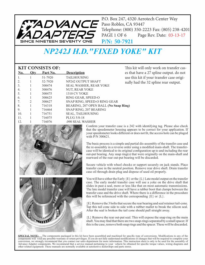
Confirm your transfer case is a 242 with identifying tag. Please also check that the speedometer housing appears to be correct for your application. If your speedometer looks different or does not fit, the access hole can be pluged with P/N 300621.
The basic process is a simple and partial dis-assembly of the transfer case and the re-assembly in a reverse order using a modified main-shaft. The transfer-case will be identical to its original configuration up to and including the rear out-put bearing. Any snap ring(s) that were originally on the main-shaft and rearward of the rear out-put bearing will be discarded.
Secure vehicle with wheel chocks or support securely on jack stands. Place transfer case in the neutral position. Remove rear drive shaft. Drain transfer case oil through drain plug and dispose of used oil properly.
You will have either the Early {E} or the {L} Late model output on the transfer case. The early model transfer case will use a yoke on the drive shaft that slides in past a seal, more or less like that on most automatic transmissions. The late model transfer case will have a rubber boot that clamps between the transfer case and the drive shaft. Where there is a difference in the procedure this will be referenced with the corresponding {E} or {L}.
{E} Remove the 3 bolts that secure the rear bearing and seal retainer/tail-cone. Tap this tail cone side to side with a rubber mallet to break the silicon seal. After the seal is broken the tail cone should pull straight away.
{L} Remove the rear out-put seal. This will expose the snap ring on the main shaft. You may find that there are two snap-rings separated by a small spacer. If this is the case, remove both snap rings and the spacer. These will be discarded.
This kit will only work on transfer cas-es that have a 27 spline output. do not use this kit if your transfer case origi-nally had the 32 spline rear output.
SPECIAL NOTE: The components packaged in this kit have been assembled and machined for specific type of conversions. Modifications to any of the components will void any possible warranty or return privileges. If you do not fully understand modifications or changes that will be required to complete your conversion, we strongly recommend that you contact our sales department for more information. This instruction sheet is only to be used for the assembly of Advance Adapter components. We recommend that a service manual pertaining to your vehicle be obtained for specific torque values, wiring diagrams and other related equipment. These manuals are normally available at automotive dealerships and parts stores.
NP242J H.D."FIXED YOKE" KITRemove the speedometer driven gear and spindle.
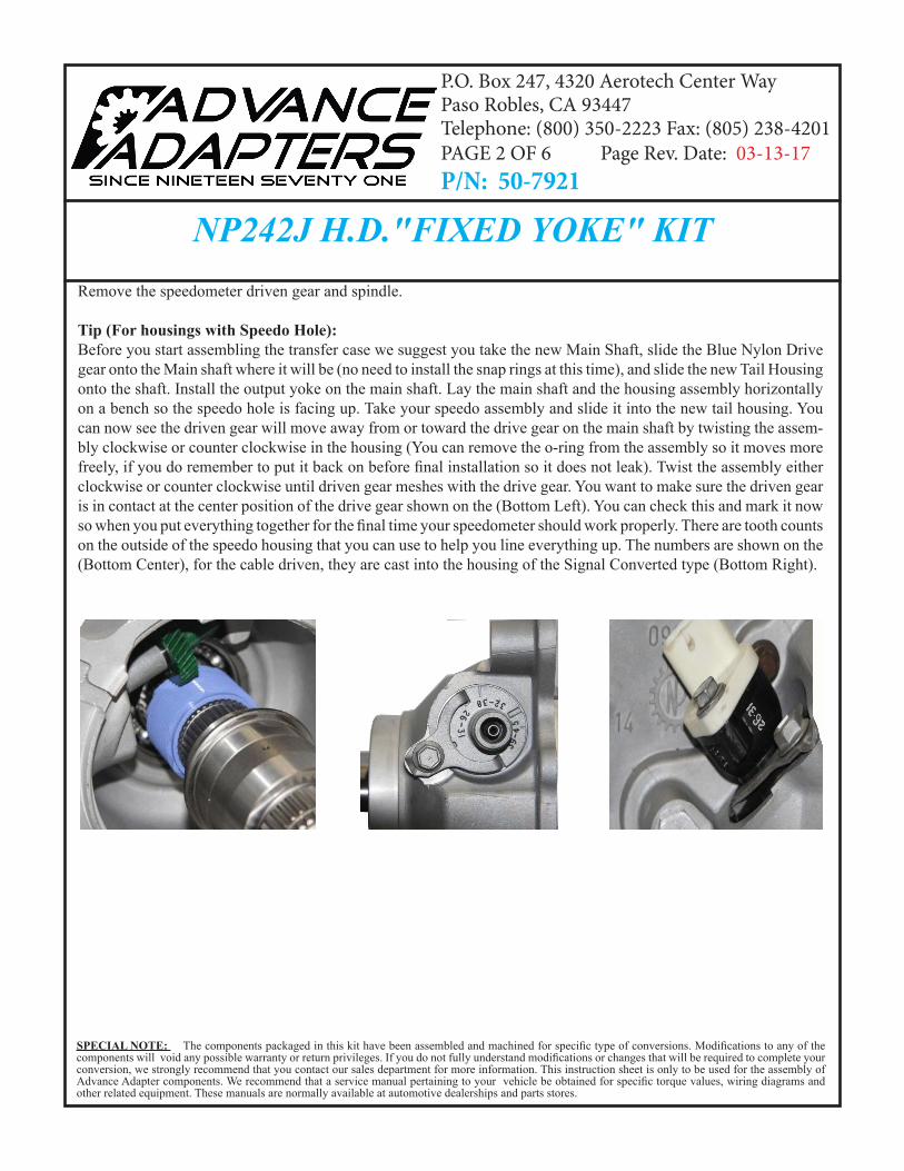
Tip (For housings with Speedo Hole):Before you start assembling the transfer case we suggest you take the new Main Shaft, slide the Blue Nylon Drive gear onto the Main shaft where it will be (no need to install the snap rings at this time), and slide the new Tail Housing onto the shaft. Install the output yoke on the main shaft. Lay the main shaft and the housing assembly horizontally on a bench so the speedo hole is facing up. Take your speedo assembly and slide it into the new tail housing. You can now see the driven gear will move away from or toward the drive gear on the main shaft by twisting the assem-bly clockwise or counter clockwise in the housing (You can remove the o-ring from the assembly so it moves more freely, if you do remember to put it back on before final installation so it does not leak). Twist the assembly either clockwise or counter clockwise until driven gear meshes with the drive gear. You want to make sure the driven gear is in contact at the center position of the drive gear shown on the (Bottom Left). You can check this and mark it now so when you put everything together for the final time your speedometer should work properly. There are tooth counts on the outside of the speedo housing that you can use to help you line everything up. The numbers are shown on the (Bottom Center), for the cable driven, they are cast into the housing of the Signal Converted type (Bottom Right).
P.O. Box 247, 4320 Aerotech Center Way Paso Robles, CA 93447Telephone: (800) 350-2223 Fax: (805) 238-4201 PAGE 2 OF 6 Page Rev. Date: 03-13-17P/N: 50-7921
SPECIAL NOTE: The components packaged in this kit have been assembled and machined for specific type of conversions. Modifications to any of the components will void any possible warranty or return privileges. If you do not fully understand modifications or changes that will be required to complete your conversion, we strongly recommend that you contact our sales department for more information. This instruction sheet is only to be used for the assembly of Advance Adapter components. We recommend that a service manual pertaining to your vehicle be obtained for specific torque values, wiring diagrams and other related equipment. These manuals are normally available at automotive dealerships and parts stores.
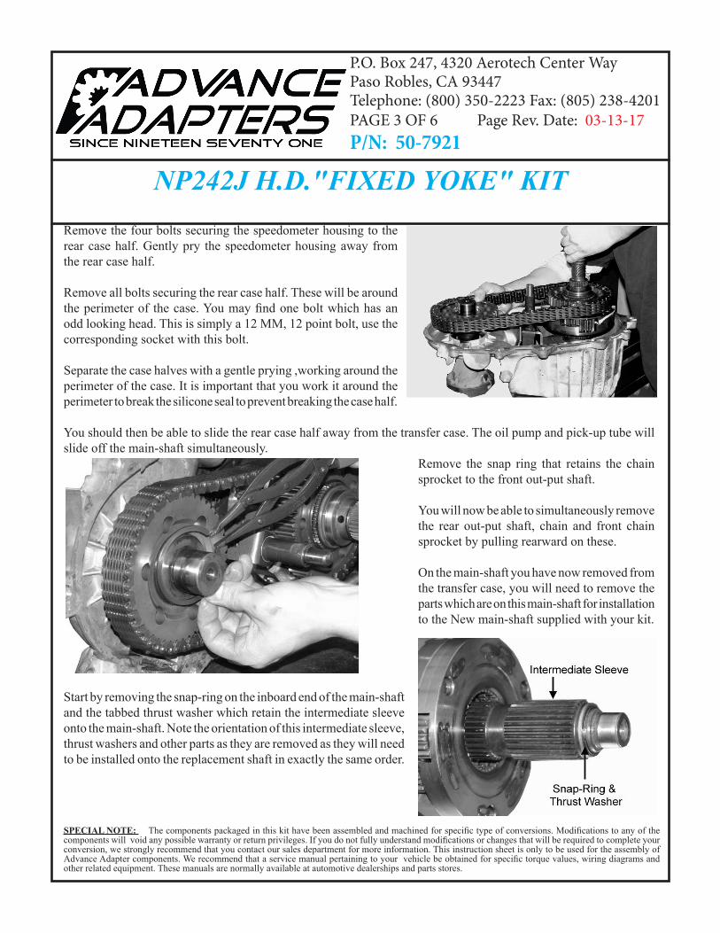
NP242J H.D."FIXED YOKE" KITRemove the four bolts securing the speedometer housing to the rear case half. Gently pry the speedometer housing away from the rear case half.
Remove all bolts securing the rear case half. These will be around the perimeter of the case. You may find one bolt which has an odd looking head. This is simply a 12 MM, 12 point bolt, use the corresponding socket with this bolt.
Separate the case halves with a gentle prying ,working around the perimeter of the case. It is important that you work it around the perimeter to break the silicone seal to prevent breaking the case half.
You should then be able to slide the rear case half away from the transfer case. The oil pump and pick-up tube will slide off the main-shaft simultaneously.
Remove the snap ring that retains the chain sprocket to the front out-put shaft.
You will now be able to simultaneously remove the rear out-put shaft, chain and front chain sprocket by pulling rearward on these.
On the main-shaft you have now removed from the transfer case, you will need to remove the parts which are on this main-shaft for installation to the New main-shaft supplied with your kit.
Start by removing the snap-ring on the inboard end of the main-shaft and the tabbed thrust washer which retain the intermediate sleeve onto the main-shaft. Note the orientation of this intermediate sleeve, thrust washers and other parts as they are removed as they will need to be installed onto the replacement shaft in exactly the same order.
P.O. Box 247, 4320 Aerotech Center Way Paso Robles, CA 93447Telephone: (800) 350-2223 Fax: (805) 238-4201 PAGE 3 OF 6 Page Rev. Date: 03-13-17P/N: 50-7921
SPECIAL NOTE: The components packaged in this kit have been assembled and machined for specific type of conversions. Modifications to any of the components will void any possible warranty or return privileges. If you do not fully understand modifications or changes that will be required to complete your conversion, we strongly recommend that you contact our sales department for more information. This instruction sheet is only to be used for the assembly of Advance Adapter components. We recommend that a service manual pertaining to your vehicle be obtained for specific torque values, wiring diagrams and other related equipment. These manuals are normally available at automotive dealerships and parts stores.
NP242J H.D."FIXED YOKE" KIT
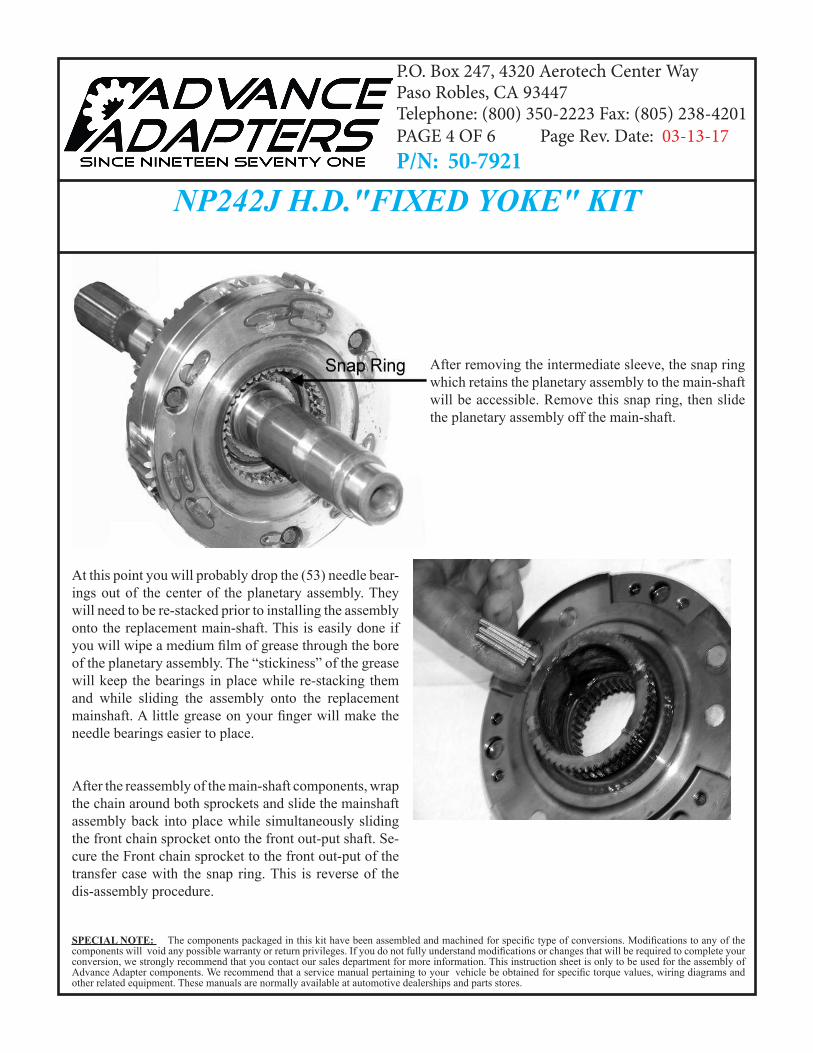
After removing the intermediate sleeve, the snap ring which retains the planetary assembly to the main-shaft will be accessible. Remove this snap ring, then slide the planetary assembly off the main-shaft.
At this point you will probably drop the (53) needle bear-ings out of the center of the planetary assembly. They will need to be re-stacked prior to installing the assembly onto the replacement main-shaft. This is easily done if you will wipe a medium film of grease through the bore of the planetary assembly. The “stickiness” of the grease will keep the bearings in place while re-stacking them and while sliding the assembly onto the replacement mainshaft. A little grease on your finger will make the needle bearings easier to place.
After the reassembly of the main-shaft components, wrap the chain around both sprockets and slide the mainshaft assembly back into place while simultaneously sliding the front chain sprocket onto the front out-put shaft. Se-cure the Front chain sprocket to the front out-put of the transfer case with the snap ring. This is reverse of the dis-assembly procedure.
P.O. Box 247, 4320 Aerotech Center Way Paso Robles, CA 93447Telephone: (800) 350-2223 Fax: (805) 238-4201 PAGE 4 OF 6 Page Rev. Date: 03-13-17P/N: 50-7921
SPECIAL NOTE: The components packaged in this kit have been assembled and machined for specific type of conversions. Modifications to any of the components will void any possible warranty or return privileges. If you do not fully understand modifications or changes that will be required to complete your conversion, we strongly recommend that you contact our sales department for more information. This instruction sheet is only to be used for the assembly of Advance Adapter components. We recommend that a service manual pertaining to your vehicle be obtained for specific torque values, wiring diagrams and other related equipment. These manuals are normally available at automotive dealerships and parts stores.
NP242J H.D."FIXED YOKE" KIT
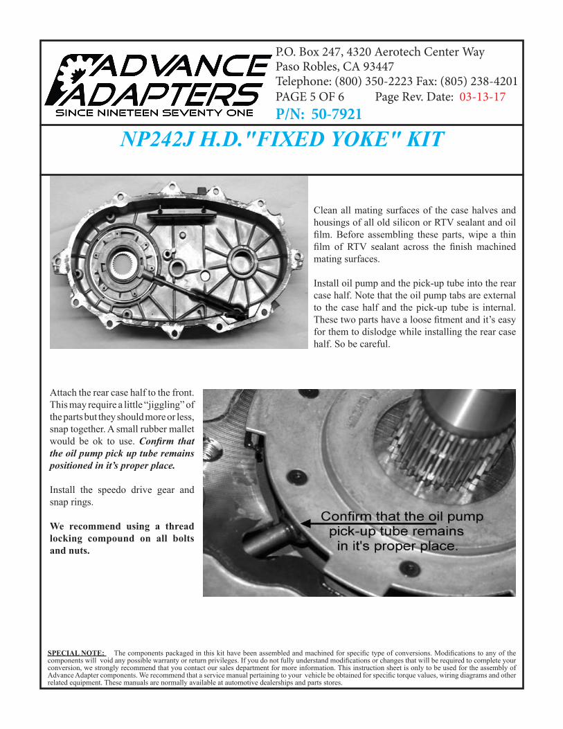
Clean all mating surfaces of the case halves and housings of all old silicon or RTV sealant and oil film. Before assembling these parts, wipe a thin film of RTV sealant across the finish machined mating surfaces.
Install oil pump and the pick-up tube into the rear case half. Note that the oil pump tabs are external to the case half and the pick-up tube is internal. These two parts have a loose fitment and it’s easy for them to dislodge while installing the rear case half. So be careful.
Attach the rear case half to the front. This may require a little “jiggling” of the parts but they should more or less,snap together. A small rubber mallet would be ok to use. Confirm that the oil pump pick up tube remains positioned in it’s proper place.
Install the speedo drive gear and snap rings.
We recommend using a thread locking compound on all bolts and nuts.
P.O. Box 247, 4320 Aerotech Center Way Paso Robles, CA 93447Telephone: (800) 350-2223 Fax: (805) 238-4201 PAGE 5 OF 6 Page Rev. Date: 03-13-17P/N: 50-7921
SPECIAL NOTE: The components packaged in this kit have been assembled and machined for specific type of conversions. Modifications to any of the components will void any possible warranty or return privileges. If you do not fully understand modifications or changes that will be required to complete your conversion, we strongly recommend that you contact our sales department for more information. This instruction sheet is only to be used for the assembly of Advance Adapter components. We recommend that a service manual pertaining to your vehicle be obtained for specific torque values, wiring diagrams and other related equipment. These manuals are normally available at automotive dealerships and parts stores.
NP242J H.D."FIXED YOKE" KIT
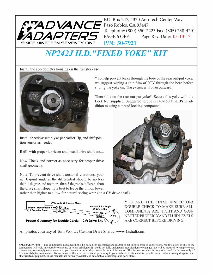
Install the speedometer housing on the transfer case.
* To help prevent leaks through the bore of the rear out-put yoke, we suggest wiping a thin film of RTV through the bore before sliding the yoke on. The excess will ooze outward.
Then slide on the rear out-put yoke*. Secure this yoke with the Lock Nut supplied. Suggested torque is 140-150 FT/LBS in ad-dition to using a thread locking compound.
Install speedo assembly as per earlier Tip, and shift posi-tion sensor as needed.
Refill with proper lubricant and install drive shaft etc....
Now Check and correct as necessary for proper drive shaft geometry.
Note: To prevent drive shaft torsional vibrations, your net U-joint angle at the differential should be no less than 1 degree and no more than 3 degree’s different than the drive shaft slope. It is best to leave the pinion lower rather than higher to allow for natural spring wrap (on a CV drive shaft).
YOU ARE THE FINAL INSPECTOR! DOUBLE CHECK TO MAKE SURE ALL COMPONENTS ARE TIGHT AND CON-NECTED PROPERLY AND FLUID LEVELS ARE CORRECT BEFORE DRIVING.
All photos courtesy of Tom Wood's Custom Drive Shafts. www.4xshaft.com
P.O. Box 247, 4320 Aerotech Center Way Paso Robles, CA 93447Telephone: (800) 350-2223 Fax: (805) 238-4201 PAGE 6 OF 6 Page Rev. Date: 03-13-17P/N: 50-7921