np#70701 instruction manual 2000w-24v marine grade … · instruction manual 2000w-24v marine grade...
TRANSCRIPT
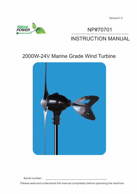
INSTRUCTION MANUAL
2000W-24V Marine Grade Wind Turbine
Version1.3
Serial number:
Please read and understand this manual completely before operating the machine.
NP#70701
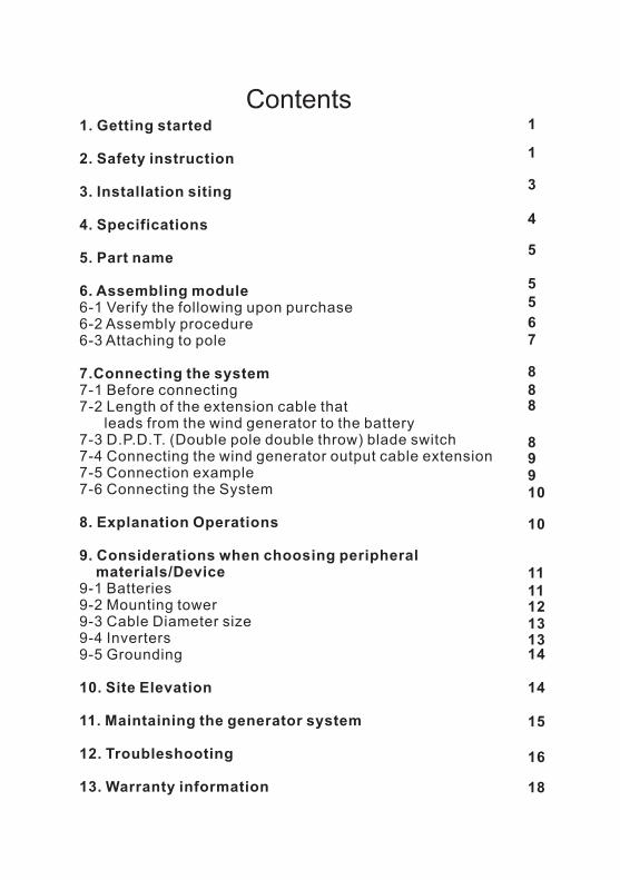
Contents1. Getting started
2. Safety instruction
3. Installation siting
4. Specifications
5. Part name
6. Assembling module6-1 Verify the following upon purchase6-2 Assembly procedure6-3 Attaching to pole 7.Connecting the system7-1 Before connecting7-2 Length of the extension cable that leads from the wind generator to the battery7-3 D.P.D.T. (Double pole double throw) blade switch7-4 Connecting the wind generator output cable extension7-5 Connection example7-6 Connecting the System
8. Explanation Operations
9. Considerations when choosing peripheral materials/Device9-1 Batteries9-2 Mounting tower9-3 Cable Diameter size9-4 Inverters9-5 Grounding
10. Site Elevation
11. Maintaining the generator system
12. Troubleshooting
13. Warranty information
1
1
3
4
5
55
67
888
89
10
10
11
131314
9
12
14
15
18
16
11
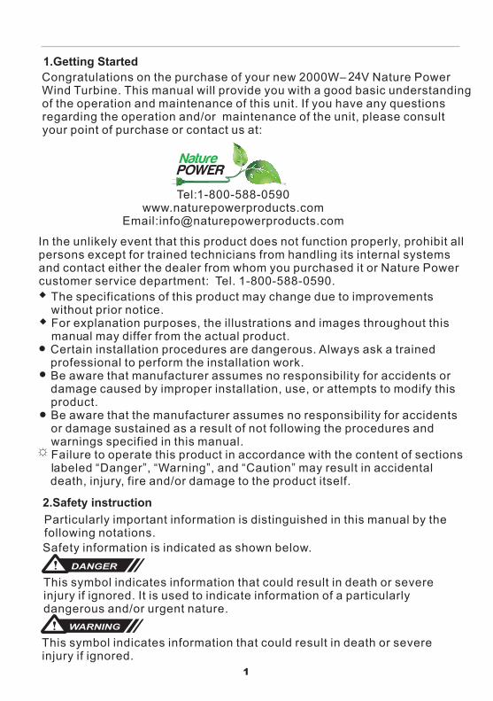
1.Getting Started
1
Congratulations on the purchase of your new 2000W– V Nature Power Wind Turbine. This manual will provide you with a good basic understanding of the operation and maintenance of this unit. If you have any questions regarding the operation and/or maintenance of the unit, please consult your point of purchase or contact us at:
Tel:1-800-588-0590www.naturepowerproducts.com
Email:[email protected]
In the unlikely event that this product does not function properly, prohibit all persons except for trained technicians from handling its internal systems and contact either the dealer from whom you purchased it or Nature Power customer service department: Tel. 1-800-588-0590.
The specifications of this product may change due to improvements without prior notice.For explanation purposes, the illustrations and images throughout this manual may differ from the actual product.Certain installation procedures are dangerous. Always ask a trained professional to perform the installation work.Be aware that manufacturer assumes no responsibility for accidents or damage caused by improper installation, use, or attempts to modify this product.Be aware that the manufacturer assumes no responsibility for accidents or damage sustained as a result of not following the procedures and warnings specified in this manual.Failure to operate this product in accordance with the content of sections labeled “Danger”, “Warning”, and “Caution” may result in accidental death, injury, fire and/or damage to the product itself.
☼
2.Safety instructionParticularly important information is distinguished in this manual by the following notations.Safety information is indicated as shown below. DANGER This symbol indicates information that could result in death or severe injury if ignored. It is used to indicate information of a particularly dangerous and/or urgent nature.
WARNING
This symbol indicates information that could result in death or severe injury if ignored.
24
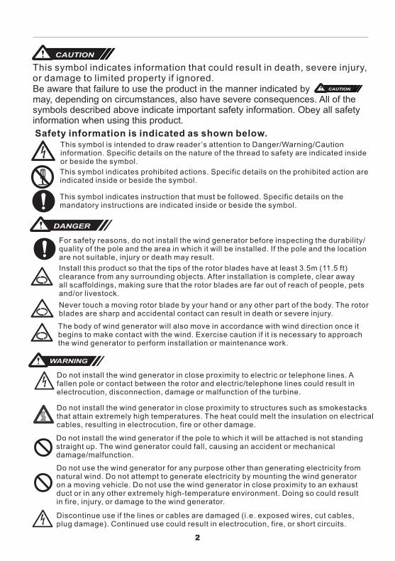
Be aware that failure to use the product in the manner indicated by may, depending on circumstances, also have severe consequences. All of the symbols described above indicate important safety information. Obey all safety information when using this product.
CAUTION
DANGER
Safety information is indicated as shown below.This symbol is intended to draw reader’s attention to Danger/Warning/Cautioninformation. Specific details on the nature of the thread to safety are indicated inside or beside the symbol.
This symbol indicates prohibited actions. Specific details on the prohibited action are indicated inside or beside the symbol.
This symbol indicates instruction that must be followed. Specific details on the mandatory instructions are indicated inside or beside the symbol.
Install this product so that the tips of the rotor blades have at least 3.5m (11.5 ft)clearance from any surrounding objects. After installation is complete, clear away all scaffoldings, making sure that the rotor blades are far out of reach of people, petsand/or livestock.
Never touch a moving rotor blade by your hand or any other part of the body. The rotor blades are sharp and accidental contact can result in death or severe injury.
The body of wind generator will also move in accordance with wind direction once it begins to make contact with the wind. Exercise caution if it is necessary to approach the wind generator to perform installation or maintenance work.
WARNING
For safety reasons, do not install the wind generator before inspecting the durability/quality of the pole and the area in which it will be installed. If the pole and the location are not suitable, injury or death may result.
Do not install the wind generator in close proximity to structures such as smokestacks that attain extremely high temperatures. The heat could melt the insulation on electrical cables, resulting in electrocution, fire or other damage.
Do not install the wind generator if the pole to which it will be attached is not standing straight up. The wind generator could fall, causing an accident or mechanical damage/malfunction.
Do not use the wind generator for any purpose other than generating electricity from natural wind. Do not attempt to generate electricity by mounting the wind generator on a moving vehicle. Do not use the wind generator in close proximity to an exhaust duct or in any other extremely high-temperature environment. Doing so could result in fire, injury, or damage to the wind generator.
Discontinue use if the lines or cables are damaged (i.e. exposed wires, cut cables, plug damage). Continued use could result in electrocution, fire, or short circuits.
2
CAUTION
This symbol indicates information that could result in death, severe injury, or damage to limited property if ignored.
Do not install the wind generator in close proximity to electric or telephone lines. A fallen pole or contact between the rotor and electric/telephone lines could result in electrocution, disconnection, damage or malfunction of the turbine.
CAUTION
Do not pull on, excessively bend, or attempt to modify the wires/cables of the wind generator. Doing so could result in cord damage, electrocution, or fire.
Never attempt to disassemble or modify the wind generator. Doing so could result in electrocution, fire, or wind generator malfunction.
Due to conditions of use, this system may not continuously supply stable electrical power. Do not attempt to use the electricity generated by the wind generator to power medical devices or other equipment related to human life systems support. Do not attempt to use the electricity generated by the wind generator to power personal computers not equipped with batteries or other auxiliary power sources.
Observe all safety precautions when working on the wind generator in high locations. Take care to ensure that hardware and other parts do not fall from the wind generator. Falling parts can cause injuries or other accidents.
Before assembling the wind generator, secure adequate space to ensure that work can be completed safely. Inadequate space can result in injuries or other accidents.
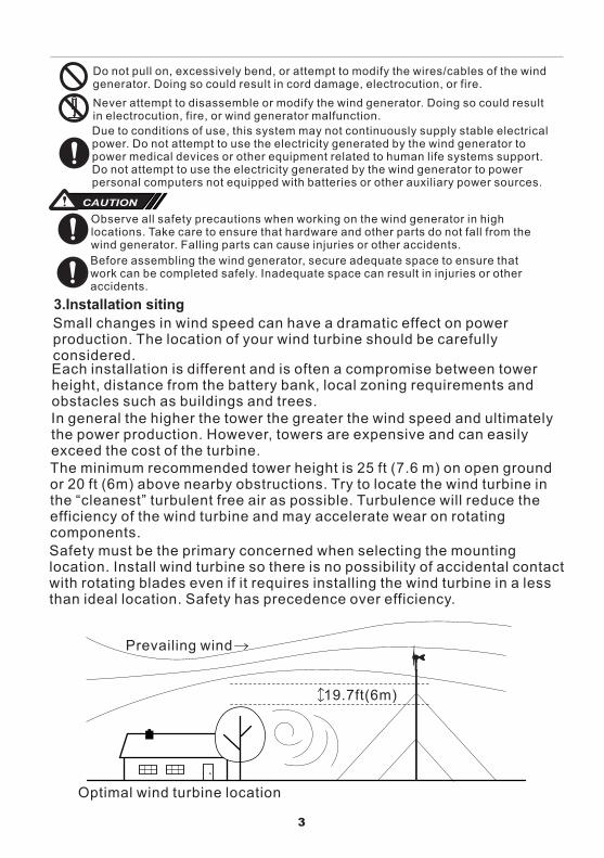
3.Installation siting
Small changes in wind speed can have a dramatic effect on power production. The location of your wind turbine should be carefully considered.
In general the higher the tower the greater the wind speed and ultimately the power production. However, towers are expensive and can easily exceed the cost of the turbine.The minimum recommended tower height is 25 ft (7.6 m) on open groundor 20 ft (6m) above nearby obstructions. Try to locate the wind turbine in the “cleanest” turbulent free air as possible. Turbulence will reduce the efficiency of the wind turbine and may accelerate wear on rotatingcomponents.
Safety must be the primary concerned when selecting the mounting location. Install wind turbine so there is no possibility of accidental contactwith rotating blades even if it requires installing the wind turbine in a less than ideal location. Safety has precedence over efficiency.
Prevailing wind
Optimal wind turbine location
19.7ft(6m)
3
Each installation is different and is often a compromise between tower height, distance from the battery bank, local zoning requirements and obstacles such as buildings and trees.
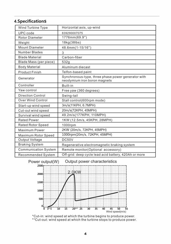
4.Specifications
3m/s(11KPH, 6.7MPH)
20m/s(72KPH, 45MPH)
2KW (20m/s, )72KPH, 45MPH
1000rpm(20m/s, )72KPH, 45MPH
839290007075UPC code
Rotor Diameter 1776mm(69.9 )''
Weight 18kg(38lbs)
Mount Diameter 48.6mm(1-15/16 )''
Number Blades 3
Horizontal axis, up-windWind Turbine Type
Blade Material Carbon-fiber
Blade Mass (per piece) 532g
Body Material Aluminum diecast
Product Finish Telfon-based paint
Generator Synchronous-type, three phase power generator with neodymium iron boron magnets
Controller Built-in
Yaw control Free yaw (360 degrees)
Direction Control Swing-tail
Over Wind Control Stall control(600rpm mode)
Start-up wind speed
49.2m/s(177KPH, 110MPH)
Cut-out wind speed
Survival wind speed
Rated Power 1KW (12.5m/s, 45KPH, 28MPH)
Rated Rotor Speed 1000rpm
Maximum Power
Maximum Rotor Speed
Output Voltage DC50V
Braking System Regenerative electromagnetic braking system
Communication System Remote monitor(Optional accessory)
Recommended System Off-grid: deep cycle lead acid battery, 420Ah or more
50
500
0
1000
1500
2000
2500
10 15 20** 25 30 35 40 45 50 55
Output power characteristicsPower output(W)
Wind speed(m/s)3*
*Cut-in: wind speed at which the turbine begins to produce power.**Cut-out: wind speed at which the turbine stops to produce power.
2.0KW
4
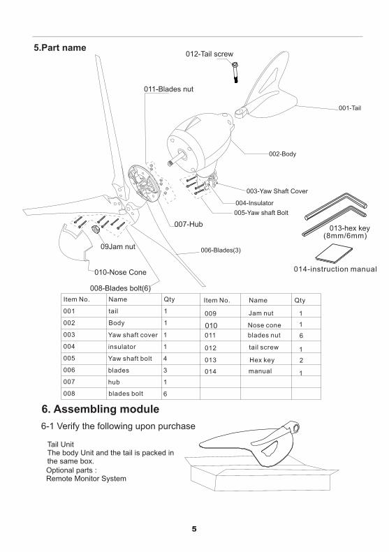
5.Part name
013-hex key
012-Tail screw
001-Tail
002-Body
003-Yaw Shaft Cover
004-Insulator
005-Yaw shaft Bolt
011-Blades nut
006-Blades(3)
007-Hub
008-Blades bolt(6)
010-Nose Cone
09Jam nut
010
(8mm/6mm)
014-instruction manual
5
6. Assembling module
6-1 Verify the following upon purchase
Tail UnitThe body Unit and the tail is packed inthe same box.Optional parts :Remote Monitor System
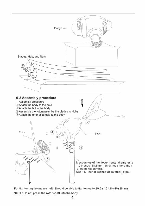
Body Unit
Blades, Hub, and Nuts
6-2 Assembly procedureAssembly procedureAttach the body to the poleAttach the tail to the bodyAssemble the rotor(assembe the blades to Hub)Attach the rotor assembly to the body.
12
34
6
Tail
BodyRotor
1
2
3
4
Mast on top of the tower (outer diameter is 1.9 inches [48.6mm]) thickness more than 3/16 inches (5mm).Use 1½ inches (schedule 80steel) pipe.
For tightening the main-shaft. Should be able to tighten up to 29.5 (40±2N.m)±1.5ft.lb
NOTE: Do not press the rotor shaft into the body.
WARNING
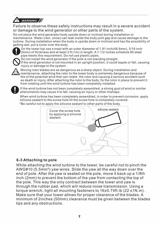
Failure to observe these safety instructions may result in a severe accident or damage to the wind generator or other parts of the system.Do not place the wind generator body upside down or inclined during installation or maintenance. Water (rain, snow) can leak inside the body joint gap and cause damage to the turbine. During installation when the body is upside down or inclined and has the possibility of getting wet, put a cover over the body.
On the tower top use a mast with an outer diameter of 1.91 inch(48.6mm), 3/16 inch(5mm) of thickness and at least 3 ft (1m) in length. A 1-1/2 inches schedule 80 steel pipe meets this requirement. Do not use plastic pipes.Do not install the wind generator if the pole is not standing straight.If the wind generator is not mounted in an upright position, it could topple or fall, causing injury or damage to the system.
Moving rotor blades are as dangerous as a sharp object. During installation andmaintenance, attaching the rotor to the tower body is extremely dangerous because of the of the potential wind that can rotate the rotor and causing a serious accident such as death or injury. After attaching the rotor to the body, fix the rotor in place to prevent it from rotating until the wind turbine has been completely installed.
If the wind turbine has not been completely assembled, a strong gust of wind or similar phenomenon may cause it to fall, causing an injury or other mishaps.
silicone sealant
When wind turbine has been completely assembled, in order to prevent corrosion, apply silicone sealant to the screw hole till the screw hole is completely covered.
*Be careful not to apply the silicone sealant to other parts of the body.
Cover the screw hole by applying a silicone sealant.
7
6-3 Attaching to pole
While attaching the wind turbine to the tower, be careful not to pinch the AWG#10 (5.5mm²) yaw wires. Slide the yaw all the way down over the end of pole. After the yaw is seated on the pole, move it back up a 1/8th inch (2mm) to prevent the bottom of the yaw from contacting the top of the pole. This way the only contract between the tower and yaw is through the rubber pad, which will reduce noise transmission. Using a torque wrench, tight all mounting fasteners to 16±0.74ft.lb (22 ±1N.m). Make sure that your tower allows for proper clearance of the blades. A minimum of 2inches (50mm) clearance must be given between the blades tips and any obstructions.
Important
7-2 Length of the extension cable that leads from the wind generator to the battery
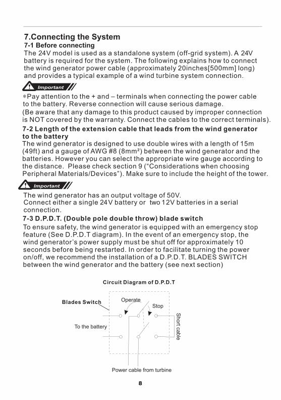
The wind generator has an output voltage of 50V.Connect either a single 24V battery or two 12V batteries in a serial connection.7-3 D.P.D.T. (Double pole double throw) blade switchTo ensure safety, the wind generator is equipped with an emergency stop feature (See D.P.D.T diagram). In the event of an emergency stop, the wind generator’s power supply must be shut off for approximately 10 seconds before being restarted. In order to facilitate turning the power on/off, we recommend the installation of a D.P.D.T. BLADES SWITCH between the wind generator and the battery (see next section)
8
7.Connecting the System7-1 Before connectingThe 24V model is used as a standalone system (off-grid system). A 24V battery is required for the system. The following explains how to connect the wind generator power cable (approximately 20inches[500mm] long) and provides a typical example of a wind turbine system connection.
Important
*Pay attention to the + and – terminals when connecting the power cable to the battery. Reverse connection will cause serious damage.(Be aware that any damage to this product caused by improper connectionis NOT covered by the warranty. Connect the cables to the correct terminals).
The wind generator is designed to use double wires with a length of 15m (49ft) and a gauge of AWG #8 (8mm²) between the wind generator and the batteries. However you can select the appropriate wire gauge according to the distance. Please check section 9 (“Considerations when choosing Peripheral Materials/Devices”). Make sure to include the height of the tower.
OperateStop
To the battery
Power cable from turbine
Short cable
Circuit Diagram of D.P.D.T
Blades Switch
9
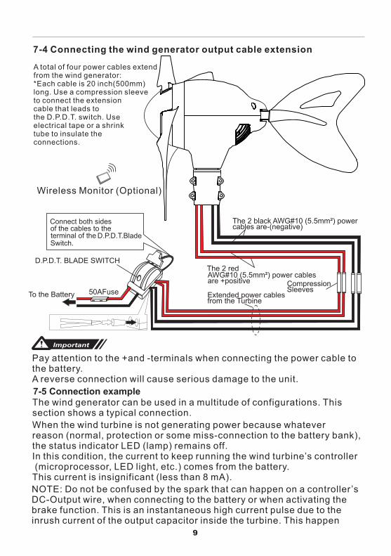
The 2 black AWG# ) power 10 (5.5mm²cables are-(negative)
The 2 red AWG#10 ( ) 5.5mm² power cablesare +positive
Extended power cablesfrom the Turbine
CompressionSleeves
To the Battery 50AFuse
D.P.D.T. BLADE SWITCH
Connect both sidesof the cables to theterminal of the D.P.D.T.BladeSwitch.
7-4 Connecting the wind generator output cable extension
Wireless Monitor (Optional)
A total of four power cables extendfrom the wind generator:*Each cable is 20 inch(500mm)long. Use a compression sleeveto connect the extensioncable that leads tothe D.P.D.T. switch. Useelectrical tape or a shrinktube to insulate theconnections.
Important
Pay attention to the +and -terminals when connecting the power cable to the battery.A reverse connection will cause serious damage to the unit.
7-5 Connection exampleThe wind generator can be used in a multitude of configurations. Thissection shows a typical connection.
When the wind turbine is not generating power because whateverreason (normal, protection or some miss-connection to the battery bank),the status indicator LED (lamp) remains off.In this condition, the current to keep running the wind turbine’s controller (microprocessor, LED light, etc.) comes from the battery. This current is insignificant (less than 8 mA).
NOTE: Do not be confused by the spark that can happen on a controller ’sDC-Output wire, when connecting to the battery or when activating thebrake function. This is an instantaneous high current pulse due to theinrush current of the output capacitor inside the turbine. This happen
7-6 Connecting the System
10
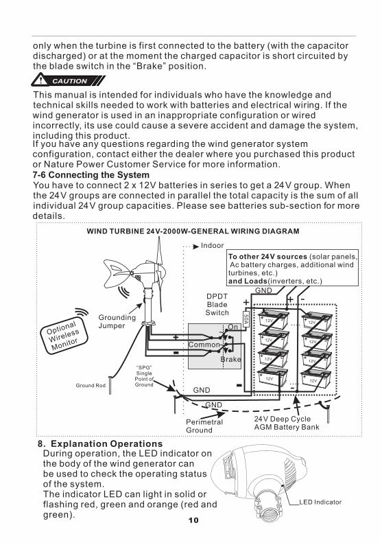
LED Indicator
8. Explanation OperationsDuring operation, the LED indicator onthe body of the wind generator canbe used to check the operating status of the system.The indicator LED can light in solid orflashing red, green and orange (red andgreen).
only when the turbine is first connected to the battery (with the capacitordischarged) or at the moment the charged capacitor is short circuited bythe blade switch in the “Brake” position.
This manual is intended for individuals who have the knowledge and technical skills needed to work with batteries and electrical wiring. If the wind generator is used in an inappropriate configuration or wired incorrectly, its use could cause a severe accident and damage the system, including this product.If you have any questions regarding the wind generator system configuration, contact either the dealer where you purchased this product or Nature Power Customer Service for more information.
You have to connect 2 x 12V batteries in series to get a 24V group. When the 24V groups are connected in parallel the total capacity is the sum of all individual 24V group capacities. Please see batteries sub-section for more details.
CAUTION
12V -+
+- Common
Brake
On
50A
-+
-+
-+
Ground Rod
12V -+
-+
-+
-+
DPDTBladeSwitch
“SPG” Single
Point of Ground
+
-
To other 24V sources (solar panels, Ac battery charges, additional wind turbines, etc.)and Loads(inverters, etc.)
Indoor
....
....-
+ -GND
PerimetralGround
24V Deep Cycle AGM Battery Bank
GroundingJumper
Optional
Wireless
Monitor
GND
GND
WIND TURBINE 24V-2000W-GENERAL WIRING DIAGRAM
12V12V
12V12V
12V12V
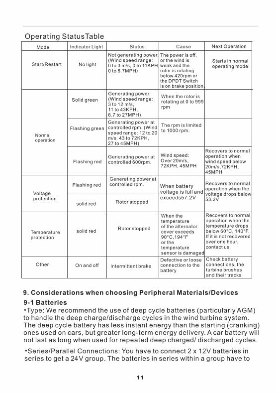
Operating StatusTableMode Indicator Light Status Cause Next Operation
Start/Restart No light
Not generating power.(Wind speed range: 0 to 3 m/s, 0 to 11KPH,0 to 6.7MPH)
The power is off,or the wind is weak and the rotor is rotating below 420rpm or the DPDT Switchis on brake position.
Starts in normaloperating mode
Normaloperation
Solid greenGenerating power.(Wind speed range:3 to 12 m/s,11 to 43KPH,6.7 to 27MPH)
When the rotor isrotating at 0 to 999rpm
Flashing greenGenerating power atcontrolled rpm. (Windspeed range: 12 to 20m/s, 43 to 72KPH,27 to 45MPH)
The rpm is limited to 1000 rpm.
Flashing redGenerating power atcontrolled 600rpm.
Voltageprotection
solid red
Generating power atcontrolled rpm. When battery
voltage is full andexceeds57.2V
Rotor stopped
Recovers to normaloperation when thevoltage drops below53.2V
Flashing red
Temperatureprotection
solid red Rotor stopped
When the temperatureof the alternator cover exceeds 90°C,194°For the temperaturesensor is damaged
Recovers to normaloperation when thetemperature dropsbelow 60°C, 140°F,If it is not recovered over one hour, contact us
Other On and off Intermittent brakeDefective or loose connection to the battery
Check battery connections, the turbine brushes and their tracks
11
•Type: We recommend the use of deep cycle batteries (particularly AGM)to handle the deep charge/discharge cycles in the wind turbine system. The deep cycle battery has less instant energy than the starting (cranking) ones used on cars, but greater long-term energy delivery. A car battery will not last as long when used for repeated deep charged/ discharged cycles.
9. Considerations when choosing Peripheral Materials/Devices9-1 Batteries
Wind speed: Over 20m/s, 72KPH, 45MPH
Recovers to normaloperation whenwind speed below20m/s,72KPH,45MPH
•Series/Parallel Connections: You have to connect 2 x 12V batteries in series to get a 24V group. The batteries in series within a group have to
12
be the same type, chemical, age and capacity (in Ah). You can connect several 24V groups in parallel to increase the battery bank capacity in Ah. However the capacity of a 24V group is the same of each single battery in series within the group (no Ah increment). Each 24V group can have different capacities. When connected in parallel the total capacity is the sum of all individual 24V group capacities.•Minimum Battery Bank Capacity in Ah: We recommend 500Ah (420 Ah minimum) when using the 2000W wind turbine as the unique power source. If there are additional 24VDC sources connected to the battery bank (i.e. solar panels, AC-battery chargers, additional wind turbines, etc.) the capacity of the batteries should be increased to avoid exceeding their maximum charging current. As an approximation, the ratio between Total-24VDC-Source-Power / 2 = Minimum recommended battery capacity. For example if there are up to 500W of solar panel power and up to 2000W of the wind turbine power connected to the battery bank, we get (500+2000) / 2 = 2500/2 = 310 Ah = minimum recommended battery bank capacity. Please check your batteries specifications.•Sizing: The size (capacity in Ah) of your battery bank depends on your application. For a specific load, the bigger the battery capacity in Ah, the longer the run time and the charging time. The charging time for the battery bank depends on its capacity in Ah, the average consumption current of the loads and the average power supplied by the turbine. This average power depends on the average wind speed condition (in MPH) at your location. The higher the average power you get from the turbine the shorter the charging time will be. As a result of that, for a specific charging time, the faster the average wind speed the bigger (in Ah) the battery bank can be. The wind turbine can supply a power from 0 to 2000W in a wind speed range from 7 to 45 MPH. You can approximate the values in between the range. With this information and using standard battery charging tables/calculators (check the Web), you can get the average charging time. So you can play with all the parameters in order to meet the requirements for your specific application.
9-2 Mounting Tower:The mounting tower that supports the wind generator is an extremely important part with respect to safety. The mast used to attach the turbine and its foundation, must be strong enough to provide adequate safety.•Location and height of the mounting tower: select a free and safe location where the ample amount of wind flow is obtained. The height of the pole must be 11.5ft (3.5m) or more to ensure safety from hazard to people.•The tower must have an upper portion of at least 3ft(1m) in length and an outer diameter of 1.9inches(48.6mm)(the1½inch schedule 80 steel pipe
13
•
•
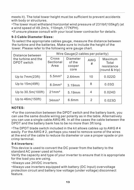
9-3 Cable Diameter Sizes:
Ω
Ω
Ω
Ω
NOTES:•
•
9-4 Inverters:
••
24
14
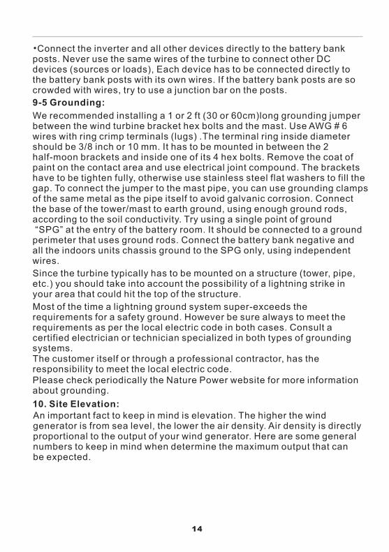
•Connect the inverter and all other devices directly to the battery bank posts. Never use the same wires of the turbine to connect other DC devices (sources or loads), Each device has to be connected directly to the battery bank posts with its own wires. If the battery bank posts are so crowded with wires, try to use a junction bar on the posts.
9-5 Grounding:
We recommended installing a 1 or 2 ft (30 or 60cm)long grounding jumper between the wind turbine bracket hex bolts and the mast. Use AWG # 6 wires with ring crimp terminals (lugs) .The terminal ring inside diameter should be 3/8 inch or 10 mm. It has to be mounted in between the 2 half-moon brackets and inside one of its 4 hex bolts. Remove the coat of paint on the contact area and use electrical joint compound. The brackets have to be tighten fully, otherwise use stainless steel flat washers to fill the gap. To connect the jumper to the mast pipe, you can use grounding clamps of the same metal as the pipe itself to avoid galvanic corrosion. Connect the base of the tower/mast to earth ground, using enough ground rods, according to the soil conductivity. Try using a single point of ground “SPG” at the entry of the battery room. It should be connected to a ground perimeter that uses ground rods. Connect the battery bank negative and all the indoors units chassis ground to the SPG only, using independent wires.
Since the turbine typically has to be mounted on a structure (tower, pipe, etc.) you should take into account the possibility of a lightning strike in your area that could hit the top of the structure.
Most of the time a lightning ground system super-exceeds the requirements for a safety ground. However be sure always to meet the requirements as per the local electric code in both cases. Consult a certified electrician or technician specialized in both types of grounding systems.The customer itself or through a professional contractor, has the responsibility to meet the local electric code.Please check periodically the Nature Power website for more information about grounding.
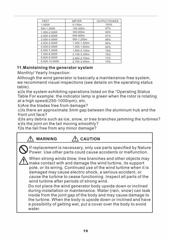
10. Site Elevation:An important fact to keep in mind is elevation. The higher the wind generator is from sea level, the lower the air density. Air density is directly proportional to the output of your wind generator. Here are some general numbers to keep in mind when determine the maximum output that can be expected.
11.Maintaining the generator system
Monthly/ Yearly Inspection:
FEET
1-500ft
METER
0-150m
OUTPUT POWER
100%
500-1,000ft
1,000-2,000ft
2,000-3,000ft
3,000-4,000ft
4,000-5,000ft
5,000-6,000ft
6,000-7,000ft
7,000-8,000ft
8,000-9,000ft
9,000-10,000ft
150-300m
300-600m
600-900m
900-1,200m
1,200-1,500m
1,500-1,800m
1,800-2,100m
2,100-2,400m
2,400-2,700m
2,700-3,000m
97%
94%
91%
88%
85%
82%
79%
76%
73%
70%
Although the wind generator is basically a maintenance-free system, we recommend visual inspections (see details on the operating status table).a)Is the system exhibiting operations listed on the “Operating Status Table For example: the indicator lamp is green when the rotor is rotating at a high speed(250-1000rpm), etc.b)Are the blades free from damage?c)Is there an approximate 3mm gap between the aluminum hub and the front unit face?d)Is any debris such as ice, snow, or tree branches jamming the turbines?e)Is the joint on the tail moving smoothly?f)Is the tail free from any minor damage?
WARNING CAUTION
15
If replacement is necessary, only use parts specified by Nature Power. Use other parts could cause accidents or malfunction.
When strong winds blow, tree branches and other objects may make contact with and damage the wind turbine, its support pole, or its wiring. Continued use of the wind turbine when it is damaged may cause electric shock, a serious accident, or cause the turbine to cease functioning. Inspect all parts of the wind turbine after periods of strong wind.Do not place the wind generator body upside down or inclined during installation or maintenance. Water (rain, snow) can leak inside from the joint gap of the body and may cause damage to the turbine. When the body is upside down or inclined and have a possibility of getting wet, put a cover over the body to avoid water.
16
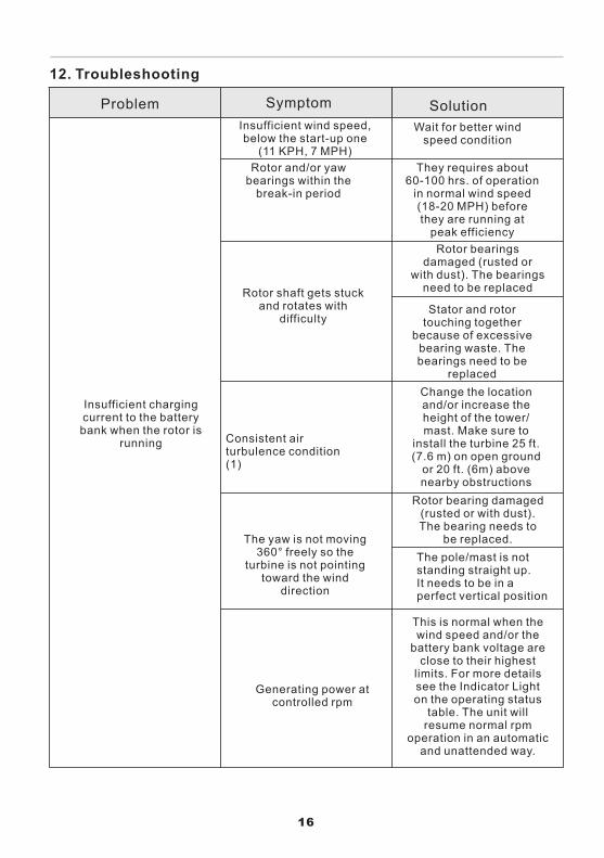
12. Troubleshooting
Problem Symptom Solution
Insufficient charging current to the battery bank when the rotor is
running
Insufficient wind speed, below the start-up one
(11 KPH, 7 MPH)
Wait for better wind speed condition
Rotor and/or yaw bearings within the
break-in period
They requires about 60-100 hrs. of operation
in normal wind speed (18-20 MPH) before they are running at
peak efficiency
Rotor shaft gets stuck and rotates with
difficulty
Rotor bearings damaged (rusted or
with dust). The bearings need to be replaced
Stator and rotor touching together
because of excessive bearing waste. The bearings need to be
replaced
Consistent air turbulence condition (1)
Change the location and/or increase the height of the tower/mast. Make sure to
install the turbine 25 ft. (7.6 m) on open ground
or 20 ft. (6m) above nearby obstructions
The yaw is not moving 360° freely so the
turbine is not pointing toward the wind
direction
Rotor bearing damaged (rusted or with dust). The bearing needs to
be replaced.
The pole/mast is not standing straight up. It needs to be in a perfect vertical position
Generating power at controlled rpm
This is normal when the wind speed and/or the
battery bank voltage are close to their highest
limits. For more details see the Indicator Light on the operating status
table. The unit will resume normal rpm
operation in an automatic and unattended way.
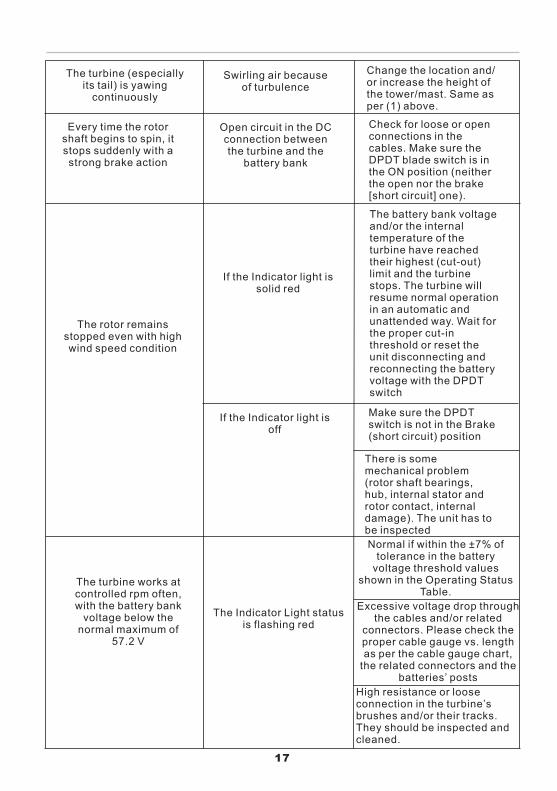
The turbine (especiallyits tail) is yawing
continuously
Swirling air because of turbulence
Change the location and/or increase the height of the tower/mast. Same as per (1) above.
Every time the rotor shaft begins to spin, it stops suddenly with a strong brake action
Open circuit in the DC connection between the turbine and the
battery bank
Check for loose or open connections in the cables. Make sure the DPDT blade switch is in the ON position (neither the open nor the brake [short circuit] one).
The rotor remains stopped even with high wind speed condition
If the Indicator light is solid red
The battery bank voltage and/or the internal temperature of the turbine have reached their highest (cut-out) limit and the turbine stops. The turbine will resume normal operation in an automatic and unattended way. Wait for the proper cut-in threshold or reset the unit disconnecting and reconnecting the battery voltage with the DPDT switch
If the Indicator light is off
Make sure the DPDT switch is not in the Brake (short circuit) position
There is some mechanical problem (rotor shaft bearings, hub, internal stator and rotor contact, internal damage). The unit has to be inspected
The turbine works at controlled rpm often, with the battery bank
voltage below the normal maximum of
57.2 V
The Indicator Light status is flashing red
Normal if within the ±7% of tolerance in the battery
voltage threshold values shown in the Operating Status
Table.
Excessive voltage drop through the cables and/or related
connectors. Please check the proper cable gauge vs. length as per the cable gauge chart,
the related connectors and the batteries’ posts
High resistance or loose connection in the turbine’s brushes and/or their tracks. They should be inspected and cleaned.
17
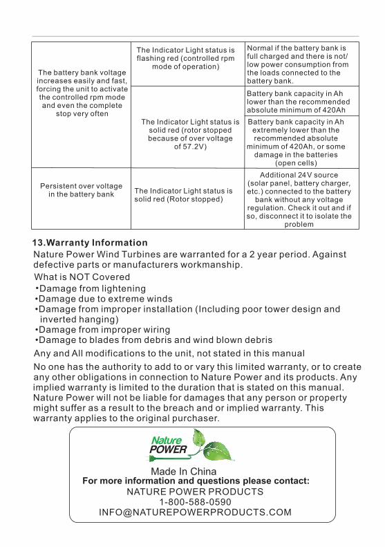
The battery bank voltage increases easily and fast, forcing the unit to activate the controlled rpm mode and even the complete
stop very often
The Indicator Light status is flashing red (controlled rpm
mode of operation)
The Indicator Light status is solid red (rotor stopped because of over voltage
of 57.2V)
Normal if the battery bank is full charged and there is not/low power consumption from the loads connected to the battery bank.
Battery bank capacity in Ah lower than the recommended absolute minimum of 420AhBattery bank capacity in Ah
extremely lower than the recommended absolute
minimum of 420Ah, or some damage in the batteries
(open cells)
Persistent over voltage in the battery bank The Indicator Light status is
solid red (Rotor stopped)
Additional 24V source (solar panel, battery charger, etc.) connected to the battery
bank without any voltage regulation. Check it out and if so, disconnect it to isolate the
problem
13.Warranty InformationNature Power Wind Turbines are warranted for a 2 year period. Against defective parts or manufacturers workmanship.What is NOT Covered •Damage from lightening •Damage due to extreme winds •Damage from improper installation (Including poor tower design and inverted hanging) •Damage from improper wiring •Damage to blades from debris and wind blown debrisAny and All modifications to the unit, not stated in this manual No one has the authority to add to or vary this limited warranty, or to create any other obligations in connection to Nature Power and its products. Any implied warranty is limited to the duration that is stated on this manual. Nature Power will not be liable for damages that any person or property might suffer as a result to the breach and or implied warranty. This warranty applies to the original purchaser.
Made In China
NATURE POWER PRODUCTS1-800-588-0590