npr 3719 kit no 59551. - sd truck springs
TRANSCRIPT

1
Technical Support
1-800-248-0892Ext. 2
MN-495(01112)
NPR 3719
Please read these instructions completely before proceeding with installation
Kit No. 59551
by
www.airliftcompany.com
N
C
A
B
J
K
F
E
H
GI
L
K
M
O
Driver Side InstallationParts List
Item P/N Description QuantityA 58571 Air Spring 2B 07940 Upper Bracket 2C 03616 Lower Bracket 2D 10622 Installation Tool 1E 21837 Air Fitting 2F 18454 3/4" Nylon Nut 2G 17124 1/2"-13 x 7/8" Bolt 2H 18414 1/2" Flat Washer, SAE 2I 01426 Clamp Bar 2J 10583 3/8" x 3.5" x 4.5" U-bolt 2K 18435 3/8" Nylock Nut 11L 18444 3/8" Flat Washer, SAE 4M 18447 3/8" Large Flat Washer 7N 17243 3/8" Washer Head Bolt 7O 17129 3/8" x 1 Self Tapper 1
AA 20086sub Air Line Assembly 1 BB 10466 Tie Strap 6 CC 21230 Valve Cap 2 DD 18405 5/16" Flat Washer 2 EE 21234 Rubber Washer 2 FF 18411 Star Washer 2 GG 21233 5/16" Hex Nut 4
IMPORTANT: This kits mountsbehind the alxe. Figure 1shows the installation for thedriver side only. Refer toFigure 7 for the passenger sideinstallation.
Figure 1

2
Technical Support
1-800-248-0892Ext. 2
NOTE: The measurement from one end of the arrow to the other end is the Normal Ride Height.
Tools Needed
IMPORTANT: Your vehicle may be equipped with a rear brake proportioning valve. Any type of load assist product couldaffect brake performance. We recommend that you check with your dealer before installing this type of product. If yourvehicle DOES NOT have a rear brake proportioning valve or is equipped with an anti-lock type brake system, installationof a load assist product will have NO EFFECT ON BRAKE SYSTEM PERFORMANCE.
7/16", 9/16" open-end or box wrenchesCrescent WrenchRatchet with 3/8", 9/16", and 1/2" deep well sockets3/8" and 5/16" drill bits (very sharp)3/8" Nut DriverHeavy Duty DrillTorque Wrench
Hose Cutter, Razor Blade, or Sharp KnifeHoist or Floor JacksSafety StandsSafety GlassesAir Compressor, or Compressed Air SourceSpray Bottle with Dish Soap/Water Solution
I. Getting Started
1. Determine the Normal Ride Height. The Normal Ride Height isthe distance between the bottom edge of the wheel-well and thecenter of the hub with the vehicle in the “as delivered” condition.In some cases, Normal Ride Height is not perfectly level.
a. Remove unusual loads and examine your vehicle from theside to ensure it is on a level surface.
b. If necessary (in cases where your leaf springs are saggingbadly), use a jack to raise the rear end so that the vehicleachieves the original “as delivered” ride height.
2. Measure the distance between the center of the hub and thebottom edge of the wheel well (Figure 2). This is the NormalRide Height. Enter the measurement below:
NORMALRIDE HEIGHT: __________ inches
3. Measure the distance between the frame and the tire. This kitrequires a minimum of 6" of clearance for a fully inflated airspring (Figure 3).
II. Raising the Vehicle
1. Raise the vehicle and remove the wheels.
2. Check the distance between the center of the hub and the bottomedge of the wheel to ensure that it is at the normal ride heightrecorded above. If not, raise the frame or lower the axle asnecessary to restore the original distance.
a. If the vehicle is raised with an axle contact hoist, place axlestands under the frame and lower the axle as needed.
b. If the vehicle is raised with a frame contact hoist, place axlestands under the axle and lower the frame as needed.
c. If the vehicle is raised with a jack and supported with axlestands on the frame, use a floor jack to lower the axle.
Figure 2
Figure 3

3
Technical Support
1-800-248-0892Ext. 2
5.1"
Figure 5
Figure 6
Figure 4
III. Assembling the Installation Tool
1. The tool provided with this kit will assist in proper setup andalignment of the air spring and will also position the upper bracketfor drilling the bolt holes. The tool attaches to the upper andlower bracket and is rigid so that it will self-align the upper bracket.The threaded section of the upper part of the tool ensures thatthe air spring can only be mounted at the correct height. The airspring will work throughout the entire threaded range on the tool.This kit will mount behind the axle.
2. Secure the upper bracket (B) to the installation tool (D) using theprovided nylon nut (F) (Figure 4).
3. Loosely attach the tool to the lower bracket (C) using 1/2" flatwasher (H) and 1/2" bolt (G). Refer to Figure 4. Leave loose foradjustment.
IV. Attaching the Lower Bracket
1. Set the assembly on the leaf spring behind the axle.
2. With the hook end of the lower bracket placed over the edge ofthe spring retaining plate (Figure 5), secure the lower bracket tothe leaf spring with the provided U-bolt (J), clamp bar (I), flatwashers (L), and lock nuts (K). Torque to 16 ft-lbs.
NOTE: The bracket will pull down flat to the leaf spring when thelock nuts are tightened.
3. The air spring will expand to 5.1" in diameter at maximum inflationpressure. Check horizontally along the shaft of the installationtool for sufficient clearance of 2.50" all around the tool (Figure6).
V. Positioning the Upper Bracket
1. Using the slot in the lower bracket, push the upper bracket againstthe frame rail.
2. Use the two nylon nuts on the threaded portion of the tool toadjust the upper bracket so that the legs are flat against theframe rail and all four holes are in the middle section of theframe. The mounting holes must not fall on the rounded edgesof the frame rail and at least 1.5" must be left above the top ofthe upper bracket for air fitting clearance.
Installation Tool
LowerBracket
Nylon Nut,Flange Down
Nylon Nut
1/2" Flat Washer
1/2" HHCS

4
Technical Support
1-800-248-0892Ext. 2
VI. Attaching the Upper Bracket
IMPORTANT: Please read this entire section completely beforedrilling any holes.
1. CAUTION: Before drilling, check the back side of the frame forclearance issues such as, brake lines, gas lines, electrical lines,etc. All obstacles need to be temporarily relocated to clear thearea.
2. DRIVER SIDE INSTALLATION:
a. Center punch the lower rear hole and drill a 3/8" hole throughthe frame.
b. Loosely install a 3/8" washer head bolt (N), a large flat washer(M), and nylock nut (K).
Figure 7
Passenger Side
c. Center punch the forward lower hole and drill a 3/8" hole through the frame.
d. Remove the tool by removing the bolt securing the tool to the lower bracket. Swing the bracket up and removethe nylon nut on the top of the upper bracket. Remove the tool. Save the hardware, as it will be reused to mountthe air spring.
e. Replace the upper bracket to the mounting location and secure at the forward, lower mounting hole location using3/8" washer head bolt (N), large flat washer (M) and nylock nut (K) as shown in Figure 1.
f. Center punch and drill a 5/16" hole for the forward upper hole and install a 3/8" self tapper (O). Tighten to 16 ft-lbs(Figure 1).
g. Drill the remaining hole out to a 3/8" diameter and install a 3/8" washer head bolt (N), a large flat washer (M), anda nylock nut (K).
3. PASSENGER SIDE INSTALLATION: Install the passenger side assembly in the same manner, with the exception tothe forward upper hole location. Drill this hole to a 3/8" diameter and install a 3/8" washer head bolt (N), a large flatwasher (M), and a nylock nut (K). No self tapper is used on the passenger side. Refer to Figure 7.
VII. Installing the Air Spring
1. Install 90 degree air swivel fitting (E) to the top of the air spring (A) (Figure 1). Use a 7/16" open end wrench beingcareful to tighten on the metal hex nut only. Tighten 1 1/2 turns. Do not over tighten. NOTE: This fitting is precoatedwith sealant.
2. Guide the fitting through the center mounting hole in the upper bracket (Figure 1).
3. Attach the air spring to the lower bracket using flat washer (H) and bolt (G). Carefully hand turn the air spring onto thelower mounting bolt. Leave loose for later adjustment.
4. Loosely, install nylon nut (F) over the air fitting and onto the upper threadpost of the air spring (Figure 1).
5
Technical Support
1-800-248-0892Ext. 2
Air Line toBellows
FF
Vehicle bodyor bumper
GG
GG
EE
DD
CC
Figure 9
Figure 8
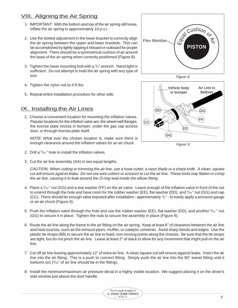
VIII. Aligning the Air Spring
1. IMPORTANT: With the bottom and top of the air spring still loose,inflate the air spring to approximately 10 p.s.i.
2. Use the slotted adjustment in the lower bracket to correctly alignthe air spring between the upper and lower brackets. This canbe accomplished by lightly tapping it inboard or outboard for properalignment. There should be a symmetrical cushion of air aroundthe base of the air spring when correctly positioned (Figure 8).
3. Tighten the lower mounting bolt with a 3/4" wrench. Hand tight issufficient. Do not attempt to hold the air spring with any type oftool.
4. Tighten the nylon nut to 4 ft-lbs.
5. Repeat entire installation procedure for other side.
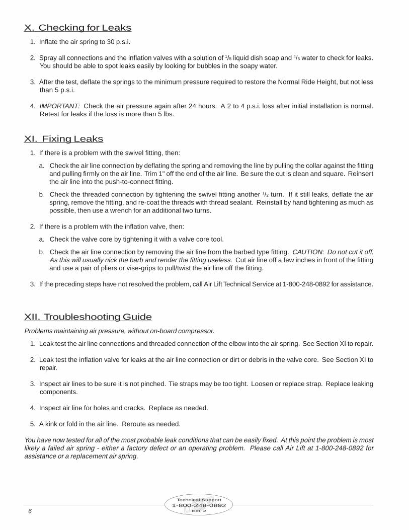
IX. Installing the Air Lines
1. Choose a convenient location for mounting the inflation valves.Popular locations for the inflation valve are: the wheel well flanges,the license plate recess in bumper, under the gas cap accessdoor, or through license plate itself.
NOTE: What ever the chosen location is, make sure there isenough clearance around the inflation valves for an air chuck.
2. Drill a 5/16 " hole to install the inflation valves.
Equ
alCushion of Air
PISTONFlex Member
3. Cut the air line assembly (AA) in two equal lengths.
CAUTION: When cutting or trimming the air line, use a hose cutter, a razor blade or a sharp knife. A clean, squarecut will ensure against leaks. Do not use wire cutters or scissors to cut the air line. These tools may flatten or crimpthe air line, causing it to leak around the O-ring seal inside the elbow fitting.
4. Place a 5/16 " nut (GG) and a star washer (FF) on the air valve. Leave enough of the inflation valve in front of the nutto extend through the hole and have room for the rubber washer (EE), flat washer (DD), and 5/16 " nut (GG) and cap(CC). There should be enough valve exposed after installation - approximately 1/2 " - to easily apply a pressure gaugeor an air chuck (Figure 9).
5. Push the inflation valve through the hole and use the rubber washer (EE), flat washer (DD), and another 5/16 " nut(GG) to secure it in place. Tighten the nuts to secure the assembly in place (Figure 9).
6. Route the air line along the frame to the air fitting on the air spring. Keep at least 6" of clearance between the air lineand heat sources, such as the exhaust pipes, muffler, or catalytic converter. Avoid sharp bends and edges. Use theplastic tie straps (BB) to secure the air line to fixed, non-moving points along the chassis. Be sure that the tie strapsare tight, but do not pinch the air line. Leave at least 2" of slack to allow for any movement that might pull on the airline.
7. Cut off air line leaving approximately 12" of extra air line. A clean square cut will ensure against leaks. Insert the airline into the air fitting. This is a push to connect fitting. Simply push the air line into the 90° swivel fitting until itbottoms out (9/16" of air line should be in the fitting).
8. Install the minimum/maximum air pressure decal in a highly visible location. We suggest placing it on the driver’sside window just above the door handle.
6
Technical Support
1-800-248-0892Ext. 2
X. Checking for Leaks
1. Inflate the air spring to 30 p.s.i.
2. Spray all connections and the inflation valves with a solution of 1/5 liquid dish soap and 4/5 water to check for leaks.You should be able to spot leaks easily by looking for bubbles in the soapy water.
3. After the test, deflate the springs to the minimum pressure required to restore the Normal Ride Height, but not lessthan 5 p.s.i.
4. IMPORTANT: Check the air pressure again after 24 hours. A 2 to 4 p.s.i. loss after initial installation is normal.Retest for leaks if the loss is more than 5 lbs.
XI. Fixing Leaks
1. If there is a problem with the swivel fitting, then:
a. Check the air line connection by deflating the spring and removing the line by pulling the collar against the fittingand pulling firmly on the air line. Trim 1" off the end of the air line. Be sure the cut is clean and square. Reinsertthe air line into the push-to-connect fitting.
b. Check the threaded connection by tightening the swivel fitting another 1/2 turn. If it still leaks, deflate the airspring, remove the fitting, and re-coat the threads with thread sealant. Reinstall by hand tightening as much aspossible, then use a wrench for an additional two turns.
2. If there is a problem with the inflation valve, then:
a. Check the valve core by tightening it with a valve core tool.
b. Check the air line connection by removing the air line from the barbed type fitting. CAUTION: Do not cut it off.As this will usually nick the barb and render the fitting useless. Cut air line off a few inches in front of the fittingand use a pair of pliers or vise-grips to pull/twist the air line off the fitting.
3. If the preceding steps have not resolved the problem, call Air Lift Technical Service at 1-800-248-0892 for assistance.
XII. Troubleshooting Guide
Problems maintaining air pressure, without on-board compressor.
1. Leak test the air line connections and threaded connection of the elbow into the air spring. See Section XI to repair.
2. Leak test the inflation valve for leaks at the air line connection or dirt or debris in the valve core. See Section XI torepair.
3. Inspect air lines to be sure it is not pinched. Tie straps may be too tight. Loosen or replace strap. Replace leakingcomponents.
4. Inspect air line for holes and cracks. Replace as needed.
5. A kink or fold in the air line. Reroute as needed.
You have now tested for all of the most probable leak conditions that can be easily fixed. At this point the problem is mostlikely a failed air spring - either a factory defect or an operating problem. Please call Air Lift at 1-800-248-0892 forassistance or a replacement air spring.

7
Technical Support
1-800-248-0892Ext. 2
XIII. Checklist
You can protect your warranty on this product and prevent unnecessary wear by ensuring the following checks havebeen made:
Section I – Installation (To be completed by the installer):
Section II - Post Installation Checklist (To be completed by the owner):
1. Clearance Test - Inflate the air springs to 60 p.s.i. and ensure there is at least 1/2 " clearance aroundeach sleeve from anything that might rub against them. Be sure to check the tire, brake drum,frame, shock absorbers and brake cables.
2. Leak Test Before Road Test – Inflate the air springs to 60 p.s.i., check all connections for leaks witha soapy water solution. See page 6 of the manual for tips on how to spot leaks. All leaks must beeliminated before the vehicle is road tested.
3. Heat Test – Be sure there is sufficient clearance from heat sources - at least 6" for air springs and airlines. If a heat shield was included in the kit - install it. If there is no heat shield, but one is required,call 1-800-248-0892.
4. Fastener Test – Recheck all bolts for proper torque.
Torque Guide:3/8 " Frame Bolts 16 ft-lbsU-bolt Lock Nuts 16 ft-lbs
5. Road Test – The vehicle should be road tested after the preceding tests. Inflate the springs to 25p.s.i. (50 p.s.i. if vehicle is loaded). Drive the vehicle 10 miles and recheck for clearance, loosefasteners and/or air leaks.
6. Operating Instructions – If professionally installed, the installer should review the operating instructionson page 8 with the owner. Be sure to provide the owner with all of the paperwork that came withthe kit.
1. Overnight Leakdown Test – Recheck air pressure after vehicle has been used for 24 hours. If pressurehas dropped more than 5 p.s.i. then, you have a leak that must be fixed. Either fix the leak yourself (seepage 6) or return to the installer for service.
2. Air Pressure Requirements – I understand that the air pressure requirements of my air spring system areas follows:
Minimum ___________ Maximum ___________
I also understand that I must inflate the air springs until the Ride Height measurement that was recordedon page 2 has been restored. Regardless of load, the air pressure should always be adjusted so that theRide Height is maintained at all times.
3. Thirty Day or 500 Mile Test. I understand that I must recheck the air spring system after 30 days or 500miles, whichever comes first. If any part shows signs of rubbing or abrasion, the source should be identifiedand moved, if possible. If it is not possible to relocate the cause of the abrasion, the air spring may needto be remounted. If professionally installed, the installer should be consulted. Check all fasteners fortightness.

8
Technical Support
1-800-248-0892Ext. 2
XIV. Maintenance and Operations
By following these steps, vehicle owners will obtain the longest life and best results from their airsprings.
1. Check the air pressure weekly.
2. Always maintain Normal Ride Height. Never inflate beyond 100 p.s.i.
3. If you develop an air leak in the system, use a soapy water solution to check all air line connections and the inflationvalve core before deflating and removing the air spring (see page 6).
4. When increasing load, always adjust the air pressure to maintain the Normal Ride Height. Increase or decreasepressure from the system as necessary to attain Normal Ride Height for optimal ride and handling. Remember thatloads carried behind the axle (including tongue loads) require more leveling force (pressure) than those carrieddirectly over the axle.
5. IMPORTANT: For your safety and to prevent possible damage to your vehicle, do not exceed maximum GrossVehicle Weight Rating (GVWR), as indicated by the vehicle manufacturer. Although your air springs are rated at amaximum inflation pressure of 100 p.s.i. The air pressure actually needed is dependant on your load and GVWR,which may be less than 100 p.s.i. Check your vehicle owners manual and do not exceed the maximum load listedfor your vehicle.
6. Always add air to springs in small quantities, checking the pressure frequently. Sleeves require less air volumethan a tire and inflate quickly.
7. Should it become necessary to raise the vehicle by the frame, make sure the system is at minimum pressure (5p.s.i.) to reduce the tension on the suspension/brake components. Use of on–board leveling systems do not requiredeflation or disconnection.
5 p.s.i. 100 p.s.i.
Failure to maintain correct minimum pressure (or pressure proportional to load),bottoming out, over-extension, or rubbing against another component will void the
warranty.
Maximum Air PressureMinimum Air Pressure
1010“The Choice of the Professional Installer”
For Technical Assistance call 1-800-248-0892
Thank you for purchasing Air Lift ProductsMailing Address: Street Address:AIR LIFT COMPANY AIR LIFT COMPANYP.O. Box 80167 2727 Snow Rd.Lansing, MI 48908-0167 Lansing, MI 48917
Local Phone: (517) 322-2144Fax: (517) 322-0240
Printed in the USA

Product Use Information
Frequently asked questions
Q. Will installing air springs increase the weight ratings of a vehicle?
No. Adding air springs will not change the weight ratings (GAWR, GCWR and/or GVWR) of a vehicle. Exceeding the GVWR is dangerous and voids the Air Lift warranty.
Q. Is it necessary to keep air in the air springs at all time and how much pressure will they need?
The minimum air pressure should be maintained at all times. The minimum air pressure keeps the air spring in shape, ensuring that it will move throughout its travel without rubbing or wearing on itself.
Q. Is it necessary to add a compressor system to the air springs?
No.Airpressurecanbeadjustedwithanytypeofcompressoraslongasitcanproducesufficientpressuretoservicethe springs. Even a bicycle tire pump can be used, but it’s a lot of work.
Q. How long should air springs last?
Iftheairspringsareproperlyinstalledandmaintainedtheycanlastindefinitely.
Q. Will raising the vehicle on a hoist for service work damage the air springs?
No. The vehicle can be lifted on a hoist for short-term service work such as tire rotation or oil changes. However, if the vehicle will be on the hoist for a prolonged period of time, support the axle with jack stands in order to take the tension off of the air springs.
Tuning the air pressure
Pressure determination comes down to three things — level vehicle, ride comfort, and stability.
1. Level vehicle
Ifthevehicle’sheadlightsareshiningintothetreesorthevehicleisleaningtooneside,thenitisnotlevel(fig.1).Raise the air pressure to correct either of these problems and level the vehicle.
2. Ride comfort
Ifthevehiclehasaroughandharshrideitmaybeduetoeithertoomuchpressureornotenough(fig.2).Trydifferentpressures to determine the best ride comfort.
3. Stability
Stabilitytranslatesintosafetyandshouldbethepriority,meaningthedrivermayneedtosacrificeaperfectlylevelandcomfortableride.Stabilityissuesincluderollcontrol,bounce,diveduringbrakingandsponginess(fig.3).Tuningout these problems usually requires an increase in pressure.
Continued on pg. 2
Bad headlight aim Rough rideSway and body rollfig. 1 fig. 2 fig. 3

Thank you for purchasing Air Lift products! For technical support, please call (800) 248-0892.Air Lift Company • P.O. Box 80167, MI 48908-0167 • (517) 322-2144 • Fax: (517) 322-0240 • www.airliftcompany.com
Guidelines for adding air:1. Startwiththevehiclelevelorslightlyabove.
2. Whenindoubt,alwaysaddair.
3. Formotorhomes,startwith50-100PSIintherearbecauseitcanbesafelyassumedthatitisheavilyloaded.
4. If the front of the vehicle dives while braking, increase the pressure in the front air bags, if equipped.
5. Ifitiseversuspectedthattheairbagshavebottomedout,increasethepressure(fig.4).
6. Adjustthepressureupanddowntofindthebestride.
7. If the vehicle rocks and rolls, adjust the air pressure to reduce movement.
8. It may be necessary to maintain different pressures on each side of the vehicle. Loads such as water, fuel, andapplianceswillcausethevehicletobeheavierononeside(fig.5).Asmuchasa50PSIdifferenceisnotuncommon.
Rev. 4/5/07
Continued from pg. 1
fig. 5fig. 4Bottoming out Unlevel Level
Air Lift Company warrants its products, for the time periods listed below, to the original retail purchaser against manufacturing defects when used on catalog-listed applications on cars, vans, light trucks and motorhomes under normal operating conditions for as long as Air Lift manufactures the product. The warranty does not apply to products that have been improperly applied, improperly installed, used in racing or off-road applications, used for commercial purposes, or which have not been maintained in accordance with installation instructions furnished with all products. The consumer will be responsible for removing (labor charges) the defective product from the vehicle and returningit,transportationcostsprepaid,tothedealerfromwhichitwaspurchasedortoAirLiftCompanyforverification.
AirLiftwillrepairorreplace,atitsoption,defectiveproductsorcomponents.Aminimum$10.00shippingandhandlingchargewillapplytoallwarrantyclaims.Beforereturninganydefectiveproduct,youmustcallAirLiftat(800)248-0892intheU.S.andCanada(elsewhere,(517)322-2144)foraReturnedMaterialsAuthorization(RMA)number.ReturnstoAirLiftcanbesentto:AirLiftCompany•2727SnowRoad•Lansing,MI•48917.
Product failures resulting from abnormal use or misuse are excluded from this warranty. The loss of use of the product, loss of time, inconvenience, commercial loss or consequential damages is not covered. The consumer is responsible for installation/reinstallation (labor charges) of the product. Air Lift Company reserves the right to change the design of any product without assuming any obligation to modify any product previously manufactured.
This warranty gives you specific legal rights and you may also have other rights that vary from state-to-state. Some states do not allow limitations on how long an implied warranty lasts or allow the exclusion or limitation of incidental or consequential damages. The above limitation or exclusion may not apply to you. There are no warranties, expressed or implied including any implied warranties of merchantability andfitness,whichextendbeyondthiswarrantyperiod.Therearenowarrantiesthatextendbeyondthedescriptiononthefacehereof.Sellerdisclaims the implied warranty of merchantability. (Dated proof of purchase required.)
Air Lift 1000 ............................... Lifetime LimitedRideControl ............................... Lifetime LimitedSlamAir ...................................... Lifetime LimitedLoadLifter 5000*........................ Lifetime LimitedEasyStreet Systems .................... 1 Year Limited
Load Controller (I) ....................... 2 Year LimitedLoad Controller (II) ...................... 2 Year LimitedSmartAir ....................................... 2 Year LimitedWireless AIR................................. 2 Year LimitedOther Accessories ....................... 2 Year Limited
*formerly SuperDuty
Warranty and Returns Policy