nrel/cp-500-38126 wind turbine generators august 2005 · ercot’s dynamic model of wind turbine...
TRANSCRIPT
National Renewable Energy Laboratory Innovation for Our Energy Future
A national laboratory of the U.S. Department of EnergyOffice of Energy Efficiency & Renewable Energy
NREL is operated by Midwest Research Institute ● Battelle Contract No. DE-AC36-99-GO10337
ERCOT’s Dynamic Model of Wind Turbine Generators Preprint E. Muljadi, C.P. Butterfield National Renewable Energy Laboratory
J. Conto, K. Donoho Electric Reliability Council of Texas
To be presented at WindPower 2005 Denver, Colorado May 15–18, 2005
Conference Paper NREL/CP-500-38126 August 2005

NOTICE
The submitted manuscript has been offered by an employee of the Midwest Research Institute (MRI), a contractor of the US Government under Contract No. DE-AC36-99GO10337. Accordingly, the US Government and MRI retain a nonexclusive royalty-free license to publish or reproduce the published form of this contribution, or allow others to do so, for US Government purposes.
This report was prepared as an account of work sponsored by an agency of the United States government. Neither the United States government nor any agency thereof, nor any of their employees, makes any warranty, express or implied, or assumes any legal liability or responsibility for the accuracy, completeness, or usefulness of any information, apparatus, product, or process disclosed, or represents that its use would not infringe privately owned rights. Reference herein to any specific commercial product, process, or service by trade name, trademark, manufacturer, or otherwise does not necessarily constitute or imply its endorsement, recommendation, or favoring by the United States government or any agency thereof. The views and opinions of authors expressed herein do not necessarily state or reflect those of the United States government or any agency thereof.
Available electronically at http://www.osti.gov/bridge
Available for a processing fee to U.S. Department of Energy and its contractors, in paper, from:
U.S. Department of Energy Office of Scientific and Technical Information P.O. Box 62 Oak Ridge, TN 37831-0062 phone: 865.576.8401 fax: 865.576.5728 email: mailto:[email protected]
Available for sale to the public, in paper, from: U.S. Department of Commerce National Technical Information Service 5285 Port Royal Road Springfield, VA 22161 phone: 800.553.6847 fax: 703.605.6900 email: [email protected] online ordering: http://www.ntis.gov/ordering.htm
Printed on paper containing at least 50% wastepaper, including 20% postconsumer waste
ERCOT’s Dynamic Model of Wind Turbine Generators
E. Muljadi1 C.P. Butterfield 1, 2 J. Conto3 K. Donoho3
National Renewable Energy Laboratory Electric Reliability Council of Texas 1617 Cole Boulevard 2705 West Lake Drive Golden, CO 80401 Taylor, Texas 76574
ABSTRACT
By the end of 2003, the total installed wind farm
capacity in the Electric Reliability Council of Texas (ERCOT) system was approximately 1 gigawatt (GW) and the total in the United States was about 5 GW. As the number of wind turbines installed throughout the United States increases, there is a greater need for dynamic wind turbine generator models that can properly model entire power systems for different types of analysis.
ERCOT took the initiative to develop wind turbine dynamic simulation models to be used in power system studies. The project’s objective was to make these models available to the public so that utility planners, wind farm developers and operators, and wind turbine manufacturers could evaluate planned wind farm developments (new or expanded).
Built under a subcontract from ERCOT on the Power System Simulation for Engineers (PSS/E) platform by Power Technologies Inc., also known as PTI (presently Siemens Power Technologies International), the wind turbine models represent different types of wind turbines installed and systems planned in the ERCOT region. Each model includes an aerodynamic model, pitch (or stall) control, a mechanical shaft, and different types of wind turbines (fixed-speed, variable-speed) and their controls.
This paper describes the ERCOT dynamic models and simulations of a simple network with different types of wind turbine models currently available. The power system network is assumed to operate under normal conditions and then a three-phase fault is introduced to simulate a disturbance in the power system network.
1National Renewable Energy Laboratory, Golden, CO 80401 2This article is offered by the Midwest Research Institute (MRI)
employees under U.S. Government Contract No. DE-AC36-99GO10337. Government and MRI retain non-exclusive, royalty-free license to publish or reproduce published articles or allow others to do so for Government purposes.
3 Electric Reliability Council of Texas, 2705 West Lake Drive, Taylor, Texas 76574.
INTRODUCTION Because there is a significant number of requests for wind farm interconnections in the ERCOT area and a lack of dynamic models of wind turbine generators, ERCOT decided to jump-start the model development process to make wind farm planning more accurate and to provide answers to difficult questions about the characteristics of a wind farm in the power system environment. At the start of this project, the participants decided that the most important modules will be made available. These modules are mostly wind turbines representing installed or planned wind farms in the ERCOT area. The wind turbines include:
1. Bonus 1300 (1.3 MW), fixed-speed, squirrel cage induction generator (SCIG), stall control wind turbine.
2. GEWE 1500 (1.5 MW), variable-speed, doubly fed induction generator (DFIG), with pitch control.
3. Vestas V47 (600 kW) and Vestas V80 (1.8 MW) variable slip, wound rotor induction generator (WRIG) with active external rotor resistance control, and pitch control.
4. NEG Micon (NM 72, 1.MW), fixed-speed, squirrel cage induction generator, stall control.
5. Kennetech (33 MVS, 400 kW), variable-speed, squirrel cage induction generator, pitch control, full power conversion.
The dynamic models discussed in this paper are based on the data provided by the manufacturers. The authors did not change the control algorithms or the transfer function provided by the manufacturers to improve turbine performance. The authors do not endorse nor criticize the algorithm implemented in the dynamic models. The implementation of the wind turbine model is solely based on the information provided by the manufacturers to PTI at the time. The changes made after the model was implemented were not included in the model and are beyond the scope of the ERCOT effort.
Because the purpose of this dynamic model is to study power system behavior, most of the mechanical systems are not modeled in detail but are sufficiently represented
1

to reflect the real turbine. Some simplifications were made, such as aerodynamic representation of the turbine models, and some others are omitted, such as the mechanical brakes, yaw drives model, and individual blade representation.
Many of the parts of the control blocks implemented in the models are not shown because of space limitation. Although the finer details (low pas filter, PID transfer functions, nonlinear characteristics of controller gains, pitch limits) of the controller are implemented inside the major blocks of the dynamic models, they are not shown in this paper.
Each turbine model is equipped with an IPLAN program that guides the user in preparing the dynamic modules related to this model. In addition, the IPLAN program initializes the load flow program before progressing into dynamic analysis. The aggregation of wind turbines, wind speed information, wind turbine parameters (i.e. inertia, blade dimension, gear ratio, shaft stiffness and damping), generator parameters (stator and rotor resistances), and the characteristics of the control systems are embedded directly or inputted from different files. The IPLAN program computes the initial conditions to solve load flow analysis and it writes the dynamic data needed by the modules associated with the wind turbine. The dynamic models written to a separate file should be combined with the dynamic models of existing plants.
The package program is expected to simulate a perturbation (the fault event) during which the post fault operation is observed. A four cycles three phase to ground fault is applied at the system bus and the impact of the fault is observed.
Figure 1 is a single line diagram of the system simulated in the next few sections. A three-phase symmetrical fault occurs at bus 151 (load bus). Because
the space is limited, and the purpose of this exercise is to show the capability of different models, the number of plot were limited to two frames for each model. The results shown for each model may be different because each turbine is built differently with a different control strategy. Thus, in this way, we do not compare oranges with apples.
Figure 1. Single line diagram of the power system network under investigation.
fault
wind turbine
BONUS 1300
Description The module for the Bonus 1300 has a three-bladed
upwind rotor with stall regulation and constant rotor speed, an induction generator coupled directly to the grid, and fail-safe safety systems with automatic air brakes and hydraulic disc brakes.
The power is limited by active stall regulation. Stall regulation is a gradual, automatic adjustment of the blade pitch that maintains maximum power at a pre-selected level. This compensates for variations in air density and other factors affecting the peak output of a wind turbine rotor.
Figure 2. Bonus 1300 Implemented Block Diagram
The generator is dual-winding induction generator. In low winds, the 6-pole small generator winding is activated for power production at 2/3 nominal speed. In higher winds, the generator is switched to the 4-pole main winding, operating at nominal speed.
Although information on the turbine’s aerodynamic characteristics was not available at the time, a dynamic module for the Bonus turbine was implemented using a generator dynamic model. The active-stall control was not implemented, and the aerodynamic characteristics were based on the turbine’s power curve (using a lookup table). Figure 2 shows a simplified control block diagram implemented in the PSS/E Program.
IPLAN Program As it is presently implemented, the IPLAN Program
takes the parameters input characterizing the wind turbine and the generator and outputs the dynamic model of the generator and the initial power and reactive power for the load flow (raw input) program. With the IPLAN program, the user can choose to activate the relay
2
protection for both over and under voltage or frequency.
Table 1. Bonus Wind Turbine Generator Dynamic Model
Descriptions
CIMTSS Induction Generator Model (fixed speed)
VTGTRP Voltage Relay FRQTRP Frequency Relay
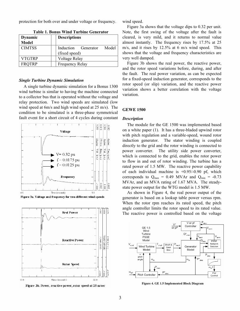
Single Turbine Dynamic Simulation A single turbine dynamic simulation for a Bonus 1300
wind turbine is similar to having the machine connected to a collector bus that is operated without the voltage and relay protection. Two wind speeds are simulated (low wind speed at 6m/s and high wind speed at 25 m/s). The condition to be simulated is a three-phase symmetrical fault event for a short circuit of 4 cycles during constant
wind speed. Figure 3a shows that the voltage dips to 0.32 per unit.
Note, the first swing of the voltage after the fault is cleared, is very mild, and it returns to normal value almost instantly. The frequency rises by 17.5% at 25 m/s, and it rises by 12.5% at 6 m/s wind speed. This shows that the voltage and frequency characteristics are very well damped.
Figure 3b shows the real power, the reactive power, and the rotor speed variations before, during, and after the fault. The real power variation, as can be expected for a fixed-speed induction generator, corresponds to the rotor speed (or slip) variation, and the reactive power variation shows a better correlation with the voltage variation.
GEWE 1500
Description The module for the GE 1500 was implemented based
on a white paper (1). It has a three-bladed upwind rotor with pitch regulation and a variable-speed, wound rotor induction generator. The stator winding is coupled directly to the grid and the rotor winding is connected to power converter. The utility side power converter, which is connected to the grid, enables the rotor power to flow in and out of rotor winding. The turbine has a rated power of 1.5 MW. The reactive power capability of each individual machine is +0.95/-0.90 pf, which corresponds to Qmax = 0.49 MVAr and Qmin = -0.73 MVAr, and an MVA rating of 1.67 MVA. The steady-state power output for the WTG model is 1.5 MW.
As shown in Figure 4, the real power output of the generator is based on a lookup table power versus rpm. When the rotor rpm reaches its rated speed, the pitch angle controller limits the rotor speed to its rated value. The reactive power is controlled based on the voltage
Figure 4. GE 1.5 Implemented Block Diagram
3

reference or power factor setting. For voltage control, the terminal voltage is compared to the reference value, and the voltage error is used to control the reactive power output of the wind turbine. For power factor control, the reactive power is controlled to keep the power factor constant at the specified value. For power factor control, both reactive power output and the real power output are used as inputs to the controller. Both voltage and frequency relays can be implemented with the wind turbine systems.
IPLAN Program The IPLAN program generates the input data for the
dynamic model of the wind turbine components listed in Table 2. The turbine includes a doubly fed induction generator, two mass shaft dynamic models, pitch controller (pitch angle and angle rates limits), control algorithm block (control for voltage or reactive power, control of real power), and voltage and frequency relay protections.
Table 2. GE 1.5 Wind Turbine Generator
Dynamic Model
Descriptions
DFIGPQ4 Doubly fed induction generator model (variable speed, including the power converter model)
TSHAFT2 Two mass shaft dynamic models TGPTCH Pitch controller CGECN2 GE wind turbine controller GE15AE Wind turbine aerodynamic for a GE
1.5 MW TWIND1 Wind speed model VTGTRP Voltage relay FRQTRP Frequency relay
Single Turbine Dynamic Simulation A single turbine dynamic simulation is a wind turbine
connected to a bus that is operated without the voltage and relay protection. Figure 5 shows that the wind turbine is operated at 20 m/s where the turbine reaches its rated power of 1.5 MW. Figure 5a shows that at this wind speed, the pitch angle is at 19.3 degrees to keep the rotor at its rated speed. When the fault occurred, the imbalance of electrical power and the aerodynamic power caused the rotor speed to vary. To keep the rotor at or below its rated speed (to avoid a runaway condition) the pitch controller adjusted the pitch angle to keep the rotor speed constant. Within a few seconds after the fault, the
rotor speed variation was damped out. Figure 5b shows the voltage, the real power, and the
reactive power on the same graph. Note that the real power varies in proportion to the rotor speed as the real power output is mapped (look-up table, power versus rpm) based on the rotor speed input. The resulting real power is smoother than the variation of rotor speed due to filtering of the rotor speed as the input to the lookup table. Although the voltage output of the turbine is controlled to be constant, during the fault, the reactive power output is limited by the converter limit. Thus, it was not possible to maintain constant voltage during the fault.
4

VESTAS V47 AND V80
Description The Vestas turbine model operates at higher than
synchronous speed. The generator output power is controlled by adjusting the effective rotor resistance during high wind speed operation. Adjustable rotor resistors are implemented through the use of power electronics mounted on the rotor of the induction generator. The output power can be adjusted to a prescribed power profile by using a mapping strategy or other nonlinear approximations of power versus rotor speed. The pitch angle can also be adjusted to limit the rotor speed. Although Vestas’ turbine can adjust the pitch angle of individual blades, the implemented model assumes that the pitch angle of all three blades is adjusted simultaneously. The pitch controller uses the rotor speed, reference speed, reference power, and actual power to refine the pitch angle control.
IPLAN Program The IPLAN Program generates the input data for the dynamic model of the wind turbine components listed in Table 3 below. The natures of the 600-kW V47 version and the 1800-kW V80 version are more or less the same. Thus the dynamic models are very similar with the exception of the input parameters. Table 3 lists the component modules for the Vestas wind turbine. These modules represent major components of the wind turbine.
Table 3. Vestas V47 or V80 Wind Turbine
Generator Dynamic Model
Descriptions
CVEST11 Wound rotor induction generator including the controller
TSHAFT2 Two mass shaft dynamic model
V80PCH Pitch controller V80AER Wind turbine aerodynamics TWIND1 Wind speed model VTGTRP Voltage relay FRQTRP Frequency relay
Single Turbine Dynamic Simulation This single turbine dynamic simulation represents the Vestas V80 only and does not include the V47 version. The fault location and condition are the same as for previous turbines. In this simulation, the wind speed is 25 m/s. The rated power is reached when the wind speed is about 20 m/s, and the opti-slip controller, which is an adjustable
Figure 6. Vestas Control Block Diagram
5

effective rotor resistance controller, is activated as soon as the wind turbine reaches its rated power. Figure 7a presents the rotor speed and the pitch angle on the same graph. Note that the blade pitch actively controls the rotor speed during and after the fault occurs. Figure 7b presents the real power, the reactive power, and the terminal voltage on the same graph. Compared to the rotor speed and pitch angle trace, the real and reactive power variations are a lot smoother because the power to the converter is controlled by the filtered rotor speed.
NEG MICON NM72
Description The NM72 is a three blade upwind turbine with an
induction generator. It has a rated power of 1500 kW, an apparent power of 1667 kVA, a synchronous rotational speed of 1200 RPM, and a rated speed (at rated power) of 1214 RPM. The rated voltage is 600 volt. NEG Micon is currently managed by Vestas.
The control block diagram, in the Figure 8, shows the major components of the wind turbine. The pitch angle controls aerodynamic power regulation. The wind speed input to the pitch controller determines the range of pitch angle and the gain for power regulation controller. The output power of the generator Pelec actively controls the pitch angle, especially in high wind speeds.
IPLAN Program The IPLAN Program for this model initializes the steady state load flow in preparation for the dynamic simulation. The program calculates the operating slip, the required capacitor compensations, and the initial pitch angle. The program also prepares the dynamic models of the generator, the pitch controller, the shaft dynamic, and the relay protections. After running the program, the user should place the generated dynamic models in the dynamic file that contains all the other plant models from the power network.
Table 4. NEG Micon NM72 Wind Turbine Generator
Dynamic Model
Descriptions
CIMTSS Induction generator model (fixed speed)
TSHAFT2 Two mass shaft dynamic models TMPTCH Pitch controller NM72AE Wind turbine aerodynamic, Micon
NM72 TWIND1 Wind speed model VTGTRP Voltage relay FRQTRP Frequency relay
Single Turbine Dynamic Simulation The fault location and condition for the Micon NM72 simulation are the same as for previous turbine simulations. In this simulation, the wind speed is 9 m/s. Thus, the wind turbine is operated below rated power. The rated power of 1.5 MW is reached when the wind speed is about 15 m/s. This wind turbine uses a direct connected squirrel cage induction generator. In high wind speed, the wind turbine operates in the stalling region.
When the fault occurs at t = 1 second, the voltage at the terminal of the wind turbine generator drops significantly. Keep in mind that the voltage is phasor quantity, an upon the fault condition, both the magnitude and the phase angle change during the transient. So do the current, real power, and reactive power.
Figure 8. NEG Micon NM72 Control Block Diagram
6
KENNETECH 33 MVS
Description The Kennetech 33 MVS is a variable-speed wind turbine with full power processing. Although this turbine is no longer manufactured, there are many turbines of this type that are still operating in the ERCOT service territory. This 400-kW turbine has two induction generators and two power converters that use ac-dc-ac systems with a dynamic model called VSCDCL. The dynamic model for aerodynamic calculation, called STATAE, defines the range of tip-speed ratio, the minimum and maximum pitch angle, and the time constant for a first order delay block. The induction generator is modeled by a dynamic model available from the library of PSSE called CIMTSS. The static pitch controller model, STPTCH, calculates the pitch angle and rate limits and defines the time constants of the filters. The two-shaft dynamic model, STSHAFT, defines the stiffness and damping, the gearbox ratio, the rotor inertia, and the pole numbers. The wind model, TWIND1, calculates the wind speed and the wind gust characteristic. The voltage or frequency relay protections (VTGTRP and FRQTRP) will disconnect the turbine when a certain voltage or frequency band is exceeded. The relay protection can protect the entire wind farm or individual wind turbines under abnormal conditions.
IPLAN Program The IPLAN Program of this model is initializes the steady state load flow as preparation for the dynamic simulation. The program calculates the operating slip, the required capacitor compensation, and the initial pitch angle. The program also prepares dynamic models of the generator, the pitch controller, the shaft dynamic, and the relay protections. After running the program, the user should place the generated dynamic models into the master dynamic file containing the other plant models from the power network.
Table 5. Kennetech 33 MVS Wind Turbine Generator
Dynamic Model
Descriptions
CIMTSS Induction generator model STSHAFT Two mass shaft dynamic models STPTCH Static interface pitch controller STATAE Static interface wind turbine aero-
dynamics VSCDCL DC link comprising two back-to-back
VSC converters and WTG related
control TWIND1 Wind speed model VTGTRP Voltage relay FRQTRP Frequency relay
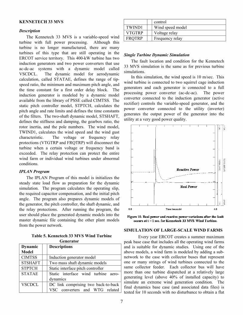
Single Turbine Dynamic Simulation The fault location and condition for the Kennetech 33 MVS simulation is the same as for previous turbine simulations. In this simulation, the wind speed is 10 m/sec. This wind turbine is connected to two squirrel cage induction generators and each generator is connected to a full processing power converter (ac-dc-ac). The power converter connected to the induction generator (active rectifier) controls the variable-speed generator, and the power converter connected to the utility (inverter) generates the output power of the generator into the utility at a very good power quality.
SIMULATION OF LARGE-SCALE WIND FARMS Every year ERCOT creates a summer maximum
peak base case that includes all the operating wind farms and is suitable for dynamic studies. Using one of the above models, a wind farm is modeled by adding a sub-network to the case with collector buses that represent one or many strings of wind turbines connected to the same collector feeder. Each collector bus will have more than one turbine dispatched at a relatively large generating level (above 40% of installed capacity) to simulate an extreme wind generation condition. The final dynamics base case (and associated data files) is tested for 10 seconds with no disturbance to obtain a flat
7

line response. This work is done in collaboration with the transmission owners where the wind farms are located.
PLAN FOR VALIDATON
Wind Turbine and Wind Farm Representation A large wind farm may have a generating
capacity of 300 MW or greater. Because it covers a very large area, each turbine will be exposed to different wind speeds and turbulence. Generally, turbines in the same vicinity can be grouped together and fed by one wind speed file to represent spatial distribution. One way to simulate this type of diversity is to compute the distance between the groups in the direction of prevailing wind. Then introduce a time shift or time delay of one wind speed time series with respect to another. The time delay is computed based on the distance between the groups and the average wind speed. Another more detailed way to represent the wind farm is with buses and transmission lines and a number of collector buses where a single wind turbine can represent many real wind turbines. This sub-network is added to the larger electric system at the point of interconnection. From the wind farm operator’s perspective, including the diversity of the wind farm is of interest. The diversity of a wind farm tends to smooth out the output of the wind farm, thus reducing the output fluctuations. Each wind turbine exposed to different wind speeds responds differently to major disturbances, but the collective output tends to cancel the output variations. Steady state data verification helps the operator determine the wind farm’s capabilities to produce the nameplate rated real power, rated reactive power, and to maintain nominal voltage under normal circumstances.
From the transmission planner’s perspective, for relay protection coordination or remedial action schemes (RAS), including the worst-case scenario is of interest. Knowing how a wind farm responds to a major disturbance can help determine the strategy and the settings of the control algorithms and protection schemes for the surrounding power systems. A worst-case scenario can be simulated by representing the entire wind farm with a single turbine. Thus, the output of the wind farm is assumed to be synchronized on a single shaft. This case can be used for checking the fault contribution from the wind farm, and to determine the size of the switchgear and relay protection needed to protect against the fault at the substation. In this analysis, a three-phase fault to the ground is used.
From the wind turbine manufacturer’s perspective, the response of a single turbine to a major
disturbance is very important. The manufacturer wants to know how the turbine responds in terms of their shaft speed oscillation, reactive power or voltage control response, output power, and voltage regulation with normal wind fluctuations or when there is a major disturbance on the transmission line.
Dynamic Model Validation and Field Measurements To build confidence in wind turbine models,
dynamic models must be validated. As mentioned in the previous section, the nature of the tests depends on the purpose of the test. Ideally, the following tests should be performed to achieve a complete validation. Wind Farm Based
The total output of the wind farm needs to be verified (real and reactive power) at the point of interconnection. Reactive power compensation in the wind farm should be taken into account. The total feeder losses (real or reactive) should be quantified if possible.
Our interest is based on the wind farm response during disturbance or during normal operation to observe the ramp-rates (ramping up/down) impact on the power systems. To determine the impacts of the ramp rates, measurements are taken at the point of interconnection (power, reactive power, voltage and currents).
This test was conducted to investigate the diversity in the wind farm. Some of the turbines will operate at rated the wind speed while some others will operate at low wind speeds. The wind speed is non-uniformly distributed in the wind farm, thus the wind farm can be represented as groups of turbines. The test can be conducted during the ramping rise of the wind speed. The test data recorded is compared to previous test results. Thus the trace of powers, voltages, and currents at the point of common coupling can be compared. The test subjects included:
- loss of grid during partial generation or full generation
- loss of excitation during partial generation or full generation
- islanding issues - short circuit on the point of common coupling or
point of interconnection of the wind farm - normal ramp up/down and the impact on voltage
and frequency at the point of interconnection Wind Turbine Based
This test will investigate the impact of the disturbance on the wind farm, the transmission or distribution network, and individual turbines. This type of test is
8

very important for large conventional fuel generators because outside disturbances can influence the dynamics of the power generation (governor, excitations systems, power system stabilizer etc.), and the impact of the response of the large generator to the power network will influence the dynamics of all power systems. Thus, there is an interaction between the large conventional generator and the power system network.
In a large wind farm with many wind turbines, the output generation of a single turbine has very little impact on the power system network, especially if the wind farm is very large and/or consists of a lot of different types of turbines. Theoretically, the collective output of the wind farm will cancel the effect from one turbine with respect to the others in the wind farm, but this hypothesis needs to be confirmed by test results.
This test will confirm whether or not the individual turbine can survive a power system network disturbance and if the control blocks reflect the model represented by the dynamic models.
In this test, the real power, reactive power, voltage, and currents of the wind turbines will need to be measured. The rotor speed, the torque, and the wind speed also need to be monitored. Several turbines at different corners of the wind farm need to be measured to verify the level of diversity in the wind farm. The electrical output at the point of interconnection should also be recorded for a comparison between the outputs of an individual turbine to the total output of the wind farm. The measurements should include:
- loss of grid during partial generation or full generation
- loss of excitation during partial generation or full generation
- short circuit on the point of common coupling or point of interconnection of the wind farm
- overriding the control setting: o Change the voltage command by step
and compare the output with the commanded signal.
o Change the power command by step and compare the output with the commanded signal.
CONCLUSION This paper summarized the project initiated by
ERCOT to provide dynamic models of wind turbines. Siemens Power Technologies International along with Electrotek Concept undertook the project to build dynamic models of the turbines available in the ERCOT system.
The dynamic models were tested using a simple
power system network. Using the same size wind farm and a single turbine representation, each model was simulated under constant wind speeds and the same fault condition. The important variables are plotted to show the response under fault conditions.
The models developed were based on input provided by the manufacturers at the time this project was undertaken. However, validation of the dynamic models by comparing them to field-test data has not yet been completed.
ACKNOWLEDGEMENTS We acknowledge the support of the U.S. Department
of Energy and ERCOT. We also thank Yuriy Kazachov of Siemens Power Technologies International, Bob Zavadil of Enernex, Jason Taylor, formerly with Electrotek Concepts, for their excellent work completing these models, and for valuable discussions during the development of these PSSE dynamic models for wind turbines.
REFERENCES [1] Miller, N.W. , Price, W.W., Sanches-Gasca, J.J.,
“Dynamic Modeling of GE 1.5 and 3.6 Wind Turbine Generators”, Version 3.0, Technical Report, GE Power Systems Energy Consulting, Schenectady, NY, December 22, 2003
[2] Zavadil, R., Kasachov, Y., “Final Report: Development and Verification of ERCOT Wind Generation Models,” Electrotek Concepts, Enernex, Power Technologies Inc. , September, 2003
[3] Y. Kazachkov, J. Feltes, R. Zavadil, "Modeling Wind Farms for Power System Stability Studies", IEEE PES 2003 General Meeting, Publication No. 03GM0946, Toronto, Canada., 2003
[4] Anderson, P.M, Power System Protection, IEEE Press Engineering Series, McGraw Hill, ISBN 0-07-134323-7.
[5] Western Systems Coordinating Councils, NERC/WSCC Planning Standards, Attachment B, June 2001.
[6] Muljadi, E., Butterfield, C.P., "Dynamic Simulation of a Wind Farm with Variable Speed Wind Turbines," Journal of Solar Energy Engineering, A Special Issue on Wind Energy, Transactions of the ASME, Vol. 125. No. 4, November 2003, pp. 410-417.
[7] Muljadi, E., Butterfield, C.P., “Dynamic Model for Wind Farm Power Systems,” Global Wind Power Conference 2004, Chicago, IL, March 29-April 1, 2004
9
F1147-E(12/2004)
REPORT DOCUMENTATION PAGE Form Approved OMB No. 0704-0188
The public reporting burden for this collection of information is estimated to average 1 hour per response, including the time for reviewing instructions, searching existing data sources, gathering and maintaining the data needed, and completing and reviewing the collection of information. Send comments regarding this burden estimate or any other aspect of this collection of information, including suggestions for reducing the burden, to Department of Defense, Executive Services and Communications Directorate (0704-0188). Respondents should be aware that notwithstanding any other provision of law, no person shall be subject to any penalty for failing to comply with a collection of information if it does not display a currently valid OMB control number. PLEASE DO NOT RETURN YOUR FORM TO THE ABOVE ORGANIZATION. 1. REPORT DATE (DD-MM-YYYY)
August 2005 2. REPORT TYPE
Conference Paper 3. DATES COVERED (From - To)
5a. CONTRACT NUMBER
DE-AC36-99-GO10337
5b. GRANT NUMBER
4. TITLE AND SUBTITLE ERCOT's Dynamic Model of Wind Turbine Generators: Preprint
5c. PROGRAM ELEMENT NUMBER
5d. PROJECT NUMBER NREL/CP-500-38126
5e. TASK NUMBER CP-500-38126
6. AUTHOR(S) E. Muljadi, C.P. Butterfield, J. Conto, and K. Donoho
5f. WORK UNIT NUMBER
7. PERFORMING ORGANIZATION NAME(S) AND ADDRESS(ES) National Renewable Energy Laboratory 1617 Cole Blvd. Golden, CO 80401-3393
8. PERFORMING ORGANIZATION REPORT NUMBER NREL/CP-500-38126
10. SPONSOR/MONITOR'S ACRONYM(S) NREL
9. SPONSORING/MONITORING AGENCY NAME(S) AND ADDRESS(ES)
11. SPONSORING/MONITORING AGENCY REPORT NUMBER
12. DISTRIBUTION AVAILABILITY STATEMENT National Technical Information Service U.S. Department of Commerce 5285 Port Royal Road Springfield, VA 22161
13. SUPPLEMENTARY NOTES
14. ABSTRACT (Maximum 200 Words) By the end of 2003, the total installed wind farm capacity in the Electric Reliability Council of Texas (ERCOT) system was approximately 1 gigawatt (GW) and the total in the United States was about 5 GW. As the number of wind turbines installed throughout the United States increases, there is a greater need for dynamic wind turbine generator models that can properly model entire power systems for different types of analysis. This paper describes the ERCOT dynamic models and simulations of a simple network with different types of wind turbine models currently available.
15. SUBJECT TERMS wind power; wind turbine generator model; Electric Reliability Council of Texas; ERCOT; wind turbine models
16. SECURITY CLASSIFICATION OF: 19a. NAME OF RESPONSIBLE PERSON a. REPORT
Unclassified b. ABSTRACT Unclassified
c. THIS PAGE Unclassified
17. LIMITATION OF ABSTRACT
UL
18. NUMBER OF PAGES
19b. TELEPHONE NUMBER (Include area code)
Standard Form 298 (Rev. 8/98) Prescribed by ANSI Std. Z39.18