nrz edc proposal for 10gbase-lrm - ieeegrouper.ieee.org/groups/802/3/aq/public/jul04/lawton_1... ·...
TRANSCRIPT

Presented by Michael Lawton, Agilent Technologies14 July 2004
Contributions and Support from:Lars Thon AelurosPiers Dawe, Michael Lawton AgilentKeith Conroy AMCCJohn Jaeger, Jonathan King, Tricia Hill, Sudeep Bhoja Big BearAndre Van Schyndel BookhamAli Ghiasi BroadcomTom Lindsay, Norm Swenson, Paul Voois ClariPhySteve Swanson CorningRyan Latchman, Judith Meester Gennum Lew Aronson FinisarJohn Ewen, Wenbin Jiang JDSU Petar Pepeljugoski IBMJens Fiedler, Stefano Bottacchi Infineon Bob Zona, Jan Peeters Weem, Martin Lobel, Henrik JohansenJesper Hanberg, Pete Kirkpatrick IntelDimitry Taich MysticomMike Fukatsu, David Jenkins, Kirk Bovill OCPYi Sun OFSNick Weiner, Chet Babla, Ben Wilcocks PhyworksPetre Popescu QuakeAbhijit Shanbhag ScinteraPaul Kolesar SystimaxBill Ring TycoKevin Witt, Badri Gomatam VitesseTom Palkert XilinxHank Blauvelt Xponent Photonics
NRZ EDC Proposal for 10GBASE-LRM

NRZ EDC ProposalJuly 2004
Page 2
Summary
Motivation for an NRZ EDC proposal
Vendor support, technical feasibility, broadest implementation scope (source, launch, cheap electronics), timing
Highlighted areas within the specification proposal:-
Parameters we can agree on today
Comparison with 10GBASE-LR (differences in blue)
Parameters in tables which warrant further study (shown in red)
Comments on implementation scope of the specification
Compliance testing strategy
Draft Proposal Document also submitted.
NRZ EDC ProposalJuly 2004
Page 3
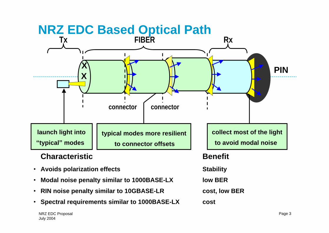
NRZ EDC Based Optical Path
Characteristic Benefit
Avoids polarization effects Stability
Modal noise penalty similar to 1000BASE-LX low BER
RIN noise penalty similar to 10GBASE-LR cost, low BER
Spectral requirements similar to 1000BASE-LX cost
Tx
connector connector
Rx
PIN
launch light into
typical modes
typical modes more resilient
to connector offsets
collect most of the light
to avoid modal noise
FIBER
XX

NRZ EDC ProposalJuly 2004
Page 4
Availability of Building Blocks
Full suite of building blocks should be available by end of 2004
Laser Driver
EDC
Tx_in Tx_out
CDR
Rx_in
Rx_out
Now10G CDR
200410G EDC chip
Now10G capable PIN
Now10G capable laser
Now10G NRZ Laser Driver
AvailabilityComponent
NRZ EDC ProposalJuly 2004
Page 5
Specification
Fiber types
Transmitter characteristics
Link Budget
Receiver characteristics
Compliance testing to be further addressed by Lew Aronson
Areas for further study
Conclusions
NRZ EDC ProposalJuly 2004
Page 6
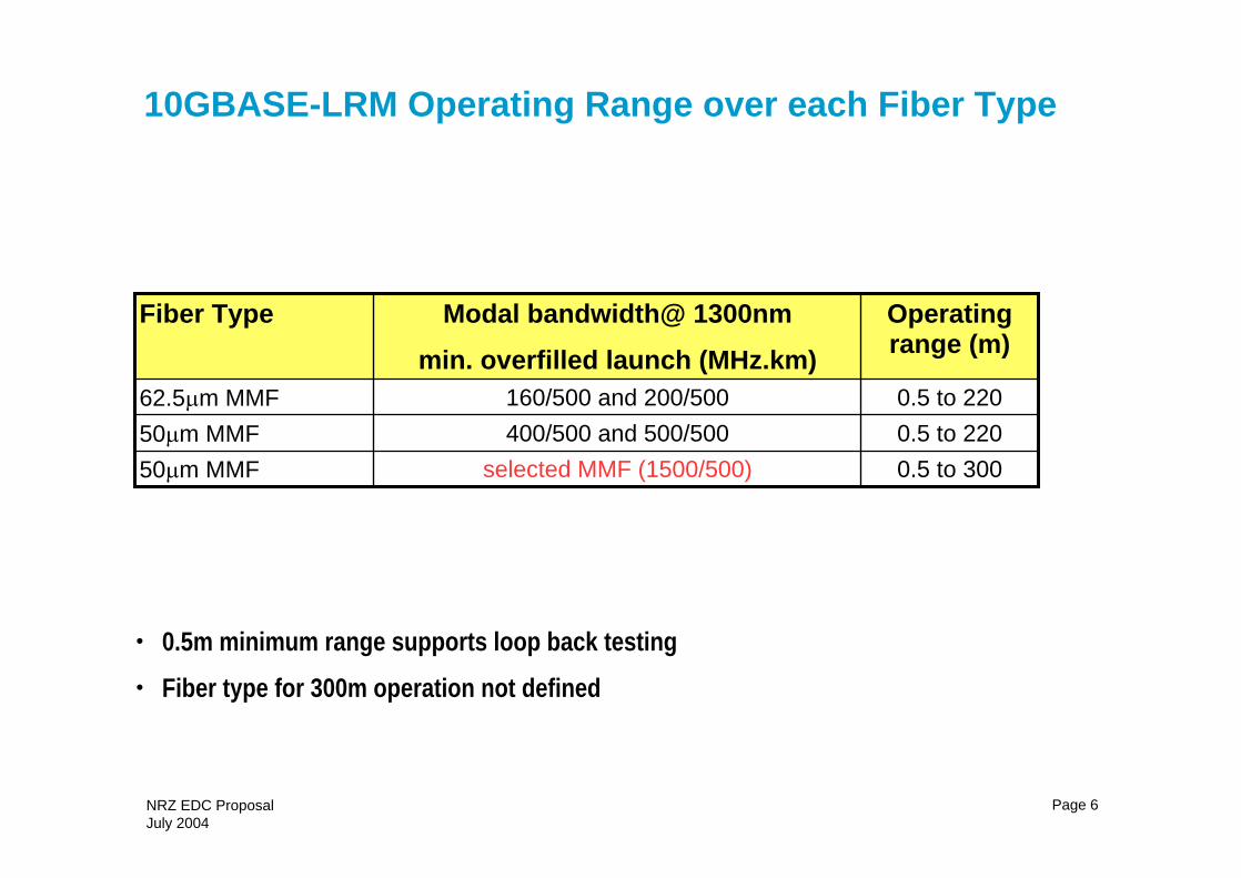
10GBASE-LRM Operating Range over each Fiber Type
0.5m minimum range supports loop back testing
Fiber type for 300m operation not defined
0.5 to 220400/500 and 500/50050 m MMF
0.5 to 300selected MMF (1500/500)50 m MMF
0.5 to 220160/500 and 200/50062.5 m MMF
Operating range (m)
Modal bandwidth@ 1300nm
min. overfilled launch (MHz.km)
Fiber Type

NRZ EDC ProposalJuly 2004
Page 7
Transmitter Parameters (TP2)
>86% in 19 m radius <30% in 4.5 m radius
NAEncircled flux test for 50 m fiber
dBm1.5maxOptical modulation amplitude
NA
{0.25, 0.40, 0.25, 0.28, 0.4}
-12
12
-128
3.5
30
-5.2
-8.2
0.5
NA
1260 to 1355
+/- 100
10.3125
10GBASE-LR
dBm-7.5minAverage launch power (informative)
dBm0.5maxAverage launch power
{0.25, 0.40, 0.25, 0.28, 0.4}*
Transmitter eye mask definition {X1, X2, X3, Y1, Y2, Y3})
>86% in 24 m radius <30% in 4.5 m radius
Encircled flux test for 62.5 m fiber
nm5maxRMS spectral width
max
max
max
min
max
min
Range
max
Nominal
Type
dBm-4.5Optical modulation amplitude
dB-12Transmitter reflectance
dB12Optical return loss tolerance
dB/Hz-128RIN12OMA
dB3.5Extinction ratio
dBm30Launch power of OFF transmitter
nm1260 to 1355Center wavelength
ppm+/- 100Signaling speed variation from nominal
GBd10.3125Signaling speed
Unit10GBASE-LRMDescription
* Relaxed eye mask TBD (subject of further study)
Are there any Tx impairments that have not yet been captured?

NRZ EDC ProposalJuly 2004
Page 8
Scope of implementation
>86% in 19 m radius <30% in 4.5 m radius
NAEncircled flux test for 50 m fiber
dBm1.5maxOptical modulation amplitude
NA
{0.25, 0.40, 0.25, 0.28, 0.4}
-12
12
-128
3.5
30
-5.2
-8.2
0.5
NA
1260 to 1355
+/- 100
10.3125
10GBASE-LR
dBm-7.5minAverage launch power (informative)
dBm0.5maxAverage launch power
{0.25, 0.40, 0.25, 0.28, 0.4} relaxed tbd
Transmitter eye mask definition {X1, X2, X3, Y1, Y2, Y3})
>86% in 24 m radius <30% in 4.5 m radius
Encircled flux test for 62.5 m fiber
nm5maxRMS spectral width
max
max
max
min
max
min
Range
max
Nominal
Type
dBm-4.5Optical modulation amplitude
dB-12Transmitter reflectance
dB12Optical return loss tolerance
dB/Hz-128RIN12OMA
dB3.5Extinction ratio
dBm30Launch power of OFF transmitter
nm1260 to 1355Center wavelength
ppm+/- 100Signaling speed variation from nominal
GBd10.3125Signaling speed
Unit10GBASE-LRMDescription
supports
DFB/FP/VCSELrelaxed eye
margin? low cost
launch?

NRZ EDC ProposalJuly 2004
Page 9
10GBASE-LRM Transmitter Power WindowTP2 power map
-8
-7
-6
-5
-4
-3
-2
-1
0
1
-5 -3 -1 1
OMA (dBm)
Mea
n p
ower
(dB
m)
Range oftransmitted power
Ext R 3.5,4,5,6 10,infinite
Similar window to 10GBASE-LR (TDP=1.7dB)
-4.5 dBm min
-7.5dBm, min (informative)
1.5 dBm max
0.5dBm max

NRZ EDC ProposalJuly 2004
Page 10
Link Power Budget for 220m (informative)
dB0.5Rx Dynamic Adaptation Penalty
dB0.2Consequent Penalty
dB4.0Total
dB0.4RIN penalty
dB0.5Modal noise penalty
dB0.4Fiber attenuation (220m)
dB2.0Connector losses
UnitsValueParameter
Link budget is very different for 10GBASE-LRM
Dispersion allowance is not part of the 10GBASE-LRM link budget
Receiver specification and compliance testing determine the required dispersion performance
Built intostressed Rx test
captured in anindividual test

NRZ EDC ProposalJuly 2004
Page 11
Interpreting the EDC Link Budget (OMA) +1.5dBm
-4.5dBm
Tx power window
connector losses = 2dB
Fiber attenuation = 0.4dB
Rx dynamic adaptation penalty= 0.5dB
Rx level for stressed
receiver sensitivity
-7.6dBm
Modal noise = 0.5dB
RIN = 0.4dB
Ideal EDC
TP3 compliance test
loss
added
noise
added
dispersion
-14.0dBm
matched filter bound sens
equiv to 13.1 dBm with LR filter
Required only for
feasibility/design work
consequent penalty = 0.2dB
EDC implementation penalty = 1.0dB
category:-
additional EDC
implementation penalty
lossemulated by
power penalty = 4.5dB
Not a spec item as AGC
performance not required

NRZ EDC ProposalJuly 2004
Page 12
TP3 Conformance Testing10GBASE-LR
Diagram taken from 802.3ae
Add jitter
filter
attenuate it TP3
the signal

NRZ EDC ProposalJuly 2004
Page 13
Freq Synthesizer
Clock Source
Patt. Generator
Stress Conditioning
A1A2
t +
Sinusoidal Amplitude Interferer
ISI Generator Block
E/OConverter?
OpticalAttenuator 62/125 Mode
Cond. Patchcord
TP3
System Under Test
PMD (RX)
PMA (RX)
PCS (RX)
SignalCharacterization
Measurement
For Future Study
Provided to Test Rx Ability to Captures Enough 62 MMF Output(Other Implementations Possible, This one Easily Available)
TP3 Conformance Testing10GBASE-LRM
Add jitter
filter the signaladd ISI
Add noise
attenuate it
Fill fiber output
Diagram taken from presentation to be given by Lew Aronson
Approach is similar to 10GBASE-LR with additional stress terms:-
Emulates ISI, Modal noise, RIN

NRZ EDC ProposalJuly 2004
Page 14
Receiver parameters (TP3)
dBm???NAmaxReceiver sensitivity with ISI only in OMA
dBm+1.5maxReceived OMA
dB0.5maxDynamic adaptation penalty
dBmNA-12.6maxReceiver sensitivity in OMA (informative)
12.3
2.2
-10.3
-14.4
0.5
1260 to 1355
+/-100
10.3125
10GBASE-LR
max
min
max
min
max
range
max
nominal
Type
dBNot usedVertical eye closure penalty
dBm-7.6 (TBC)(Static) Stressed receiver sensitivity in OMA (with ISI and sinusoidal jitter and noise applied)
GHz?3dB electrical bandwidth
dBm-9.9Average receive power (informative)
dBm0.5Average receive power
nm1260 to 1355Center wavelength
ppm+/-100Signalling speed variation from nominal
GBd10.3125Nominal signalling speed
Units10GBASE-LRMParameter

NRZ EDC ProposalJuly 2004
Page 15
Areas for further study Transmitter
Eye mask specification
Determine launch test definition and limits
Extinction ratio
Link budget
Agree dynamic adaptation penalty
Validate equalization penalties with channel model work
Receiver
Define stressed test and limits
Receiver compliance testing to be addressed in a presentation by Lew Aronson

NRZ EDC ProposalJuly 2004
Page 16
Conclusions
NRZ EDC standardization progress:-
Demonstrated strong technical feasibility
Presented draft specification with broad scope for implementation
Transmitter is well defined with only two open issues:-
launch test
Relaxed Eye mask margin test
The link budget is defined (detailed validation required)
based on low mode dependent loss and resulting low modal noise penalty
Well considered proposals presented for conformance testing
Progress in line with standardization milestones
Hardware progress supports timely product development

NRZ EDC ProposalJuly 2004
Page 17
Motion 8
Move that the 802.3aq task force adopt the NRZ EDC based proposal (lawton_01_0704) all of diagrams on page 10, 11 & 13 in aronson_2_0704 as the basis for on-going committee tasks in order to focus & progress the work towards a draft standard as modified according to the notes 1 and 2 below
Note 1: this motion does not change the draft TF timeline nor does it preclude new proposals from being brought forward in the September interim. It does direct the task force to work on key areas of the NRZ EDC proposal.
Note 2: All the table entries in lawton_01_0704 in red & all of diagrams from pgs 10, 11 & 13 in aronson_2_0704 shall be considered and identifed as TBD , with a corresponding Editors note based upon the placeholder value to be considered by the value/parameter in red
Moved: Mike Lawton Second: Pete Hallemeier
Y/N/A 59/0/2
NRZ EDC ProposalJuly 2004
Page 18
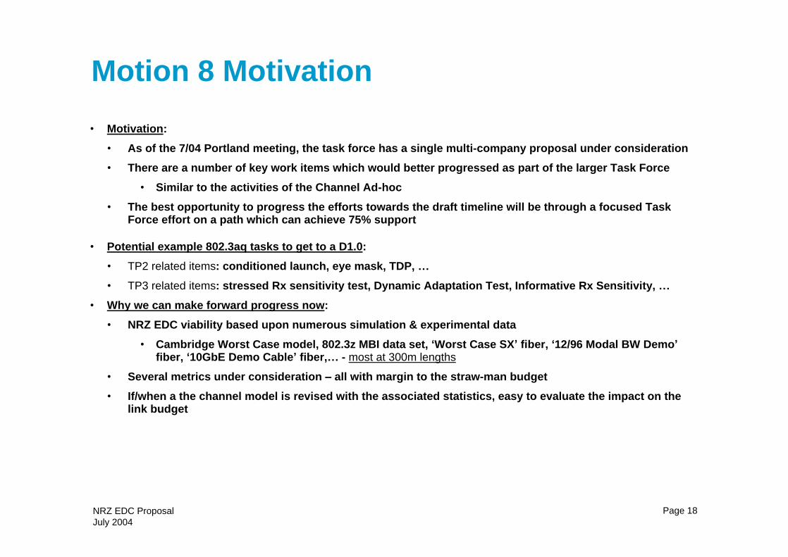
Motion 8 Motivation
Motivation:
As of the 7/04 Portland meeting, the task force has a single multi-company proposal under consideration
There are a number of key work items which would better progressed as part of the larger Task Force
Similar to the activities of the Channel Ad-hoc
The best opportunity to progress the efforts towards the draft timeline will be through a focused Task Force effort on a path which can achieve 75% support
Potential example 802.3aq tasks to get to a D1.0:
TP2 related items: conditioned launch, eye mask, TDP,
TP3 related items: stressed Rx sensitivity test, Dynamic Adaptation Test, Informative Rx Sensitivity,
Why we can make forward progress now:
NRZ EDC viability based upon numerous simulation & experimental data
Cambridge Worst Case model, 802.3z MBI data set, Worst Case SX fiber, 12/96 Modal BW Demo fiber, 10GbE Demo Cable fiber, - most at 300m lengths
Several metrics under consideration all with margin to the straw-man budget
If/when a the channel model is revised with the associated statistics, easy to evaluate the impact on the link budget
NRZ EDC ProposalJuly 2004
Page 19
Items in red
Definition of MMF for 300m
Tx
Eye mask specification
Launch test
Extinction ratio
Additional Tx impairments
Link Budget
ISI Adaptation penalty
Rx
Static Rx stressed test
Dynamic Rx stressed test
Normative Rx sensitivity (in presence of ISI) test

NRZ EDC ProposalJuly 2004
Page 20
TP3- Normative (Static) Stressed Sensitivity Test (page 10 aronson_02_0704)
Goals:
Simplest Test Which Adequately Stresses EDC Start Really Simple!
Reuse as Much 10GBASE- LR Stressed RX Test Hardware As Practical
Avoid User Tradeoff Choices Allowed in LR Stressed Test
Proposed Parameters (to be included in 10GBASE-LRM receive characteristics table)
2 Peak Impulse Response.
A2/A1 ~ 1.5 (?)
t Chosen to Yield Target Figure or Merit (Based on Allocated EDC Link Penalty) and Representative of DMD span of channel model
Choose One Sinusoidal Jitter Frequency and Amplitude from the 10GBASE-LR Mask
Add Sinusoidal Interferer to Generate S/N Equivalent to Modal Noise and RIN Penalties Assumed in Link Budget. Calculate and define as specific S/N
E/O Converter Provides Linear Response and 3.5 dB ER Output
Freq Synthesizer
Clock Source
Patt. Generator
Stress Conditioning
+
Sinusoidal Amplitude Interferer
ISI Generator Block E/OConverter?
OpticalAttenuator 62/125 Mode
Cond. Patchcord
TP3
System Under Test
PMD (RX)
PMA (RX)
PCS (RX)
SignalCharacterization
MeasurementFor Future Study
If Needed to Limit r/f of E/O (Gives minimum impulse width)
Provided to Test Rx Ability to Captures Enough 62 MMF Output(Other Implementations Possible, This one Easily Available)

NRZ EDC ProposalJuly 2004
Page 21
TP3- Adaptation Speed Test(page 11 aronson_02_0704)Goals:
Simplest Test to Establish Adequate EDC Adaptation Speed
Decouple from Stressed RX Test, Do not Include SJ and Amplitude Noise
Likely Used Only in IC Development and XCVR Design Verification, But Still Normative
Choose Minimum OMA and Test for < 1e-12 BER Over Minimum ISI Cycle
Is an Initialization Time Spec / Test Needed or is it Implicit in Form Factor MSAs
Probably needed but outside scope of IEEE specification
A1A2
t
Patt. Generator E/OConverter
OpticalAttenuator 62/125 Mode
Cond. Patchcord
PMD (RX)
Shift Power Sinusoidally and Completely Between A1 and A2 But Retain A Larger Fixed Peak Specify Adaptation Rate in Receive
Characteristics Table
Rate of Oscillation Cycle Between A1 and A2
Chosen using Measurement Experiments on Time Variation of Perturbed Fiber Link
Measure Penalty for Dynamic (At Specified Test Rate) vs Static ISI
Static case probably being the worst specific ISI case in the dynamic cycle, OR
Same much slower (1000x?) rate
Parameters included in 10GBASE-LRM Receive Characteristics Table.
1
TP3
Fixed PeakTime varying peaks A1,A2

NRZ EDC ProposalJuly 2004
Page 22
TP3- Simple Informative Sensitivity Test(page 13 aronson_02_0704)
Goals:
EDC Relevant Test Equivalent to Informative Basic Sensitivity Test in 802.3ae
Low Noise, No SJ Signal with Simple ISI Block
Provide Simplest Test For Use in Day-to-Day Measurements Such as Manufacturing
Patt. Generator
A1A2
t
2.3 GHz BT Filter(500 MHz/km / 0.22km)
E/OConverter
OpticalAttenuator 62/125 Mode
Cond. Patchcord
PMD (RX)
Option 1 - Simplest:
Option 2 If Option 1 is Considered Inadequate:
Patt. GeneratorE/O
ConverterOptical
Attenuator 62/125 Mode Cond. Patchcord
PMD (RX)
Same ISI Block as Stressed Test
Need to Calculate Required Informative Sensitivity for Receive Characteristics Table
Not a Clear Way to Do So, Requires Further Study
TP3
TP3