nss-8000 installation manual - on time auto equipment manual.pdf · nss-8000 installation manual ....
TRANSCRIPT

NSS-8000 Installation Manual

2
ATTENTION
By following the instructions in this manual you can save
yourself much time, frustration and money. The installation of
your lift will take 4-5 hours. Do not rush. It is better to spend
a few extra minutes and do the job right. If you will avoid the
following common mistakes your lift will go together easily
and serve you well for many years.
1. Do not attempt to use the power unit to extend your
cylinder. This must be done manually.
2. If you do not know how to wire your motor, get
professional help.
3
3. Make sure all cables are on pulleys before operating your
lift.
4. Always lower your lift onto the safety locks; this will
protect your power unit. Your power unit will not raise a
car while the pump is loaded.
5. Before using your lift, lubricate the inside of the four
columns. WD-40 or spray silicate works best.
6. Do not over tighten the hydraulic fittings.
We have sold over 25,000 of these style lifts. These six things
are the most common mistakes people make. If you will follow
your manual and avoid these pitfalls, you will be proud of your
lift.
IMPORTANT SAFETY INSTRUCTIONS Read these safety instructions entirely! Failure to read these instructions may result in injury to user, other people within the area of the lift, or vehicles. We are not responsible for any injury
or damage as a result of neglecting to carefully read and follow these instructions.
Always lock the lift in place before going under the vehicle. Never allow anyone to go under the lift when raising or lowering.
INSPECT your lift daily. Never operate if it malfunctions or if is has broken or damaged parts. Repairs should be made with original equipment parts. ATTENTION! LOOK OUT!
Routine check of safety latch system is very important - the discovery of device failure before needed could save you from expensive property
damage, lost production time, serious personal injury and even death. Operating controls are designed to close when released. Do not block open
or override them.
4
NEVER overload your lift. Manufacturer’s rated capacity is shown on
nameplate affixed to the lift. ALWAYS know the gross weight of vehicle. NEVER use the lift to raise one end or one side of vehicle.
NEVER raise vehicle with anyone inside it. No one should be in the lift area during operation.
ALWAYS keep lift area free of obstructions, grease, oil, trash and other debris. Before lowering lift, be sure tool trays, stands, etc. are removed
from under vehicle. Release locking devices before attempting to lower lift. Adequate ventilation should be provided when working on internal
combustion engines. Use only manufacturer’s recommended attachments.
KEEP HANDS AND FEET CLEAR. Remove hands and feet from any moving parts. Keep feet clear of lift when lowering. Avoid pinch points.
GUARD AGAINST ELECTRIC SHOCK. This lift must be grounded while in use to protect the operator from electric shock.
DANGER! The power unit used on this lift contains high voltage.
Disconnect power at the receptacle before performing any electrical repairs. Secure plug so that it cannot be accidentally plugged in during service.
WARNING! RISK OF EXPLOSION. This equipment has internal arcing or sparking parts which should not be exposed to flammable vapors. This machine should not be located in a recessed area or below floor level.
MAINTAIN WITH CARE. Keep lift clean for better and safe performance. Follow manual for proper lubrication and maintenance instructions. Keep control handles and/or buttons dry, clean and free from grease and oil.
STAY ALERT. Watch what you are doing. Use common sense. Be aware.
CHECK FOR DAMAGED PARTS. Check for alignment of moving parts, breakage of parts or any condition that may affect its operation. Do not use lift if any component is broken or damaged.
NEVER remove safety related components from the lift. Do not use lift if safety related components are damaged or missing.

5
ALWAYS wear safety glasses. Every day eyeglasses only have impact resistant lenses. They are not safety glasses.
READ AND UNDERSTAND ALL SAFETY WARNINGS & PROCEDURES BEFORE OPERATING LIFT. POST THESE SAFETY TIPS WHERE THEY WILL BE A CONSTANT
REMINDER TO YOUR LIFT OPERATOR. FOR INFORMATION SPECIFIC TO THE LIFT, ALWAYS REFER TO THE LIFT MANUFACTURER’S MANUAL.
Improper installation can cause accelerated wear, resulting catastrophic failure which may cause property damage and / or bodily injury. Manufacturer will assume no liability for loss or damage of any kind, expressed or implied, resulting from improper installation or use of this product. Read this installation manual in its entirety before attempting to install or operate the lift. SELECTING SITE: Before installing your new lift, check the following.
OVERHEAD OBSTRUCTIONS: The area where the lift will be located should be free of overhead obstructions such as heaters, building supports, electrical lines
etc. FLOOR REQUIREMENTS: Visually inspect the site where the lift is to be
installed and check for cracked or defective concrete. This lift must be installed on a solid level concrete floor with no more than 2 degrees of slope. A level floor is suggested for proper installation and level lifting. If a floor is of questionable
slope, consider a survey of the site and/or the possibility of pouring a new level concrete slab. This lift is designed to be installed on a minimum of 4” thick, 3500psi, steel reinforced concrete. Do not install this lift on asphalt, wood, or any
other surface other than described. This lift is only as strong as the foundation on which it is installed. DO NOT install this lift outdoors unless special consideration has been made to
protect the power unit from weather conditions. DO NOT begin installation with lift close to wall. It is necessary to leave adequate clearance for installing safety linkage rods. Allow 60” for clearance. (See Fig.1)

6
NOTE The power unit can be placed in one of two locations, front left or rear right (See Fig. 1)
Unpacking: Unpacked the lift close to the installation site. Layout a chalk line on the floor following the floorplan (See Fig.1).
Stand the columns in place making sure to position the power unit mounting bracket at the correct location and the lock blocks facing outward.
TOOLS recommended "Rotary Hammer Drill Or Similar ( If Anchoring ) "Medium Crescent Wrench "3/4" Masonry Bit ( If Anchoring / Not required) "Medium Pipe Wrench
"Hammer "Crow Bar "4 Foot Level "Chalk Line "Open-End Wrench Set: 7/16" - 1-1/8" "Medium Flat Screwdriver
"Socket And Ratchet Set: 7/16" - 1-1/8" "Tape Measure: 25 Foot Minimum "Hex-Key / Allen Wrench Set "Needle Nose Pliers
COLUMN & CROSSRAIL INSTALLATION Lay down rear columns. Position the
crossrail at the top of the two columns. (both cross rails are the same ) Install the crossrail in the column by sliding the plastic guide blocks into the column channel. The safety latch must be positioned with bevel side to the leg top, and
safety latch facing towards the outside of the lift when you stand the columns back up. Manually open the safety latch devise on each side of the crossrail and slide the crossrail down until it rests on the safety lock position closest to the
floor. Repeat the procedure for the remaining columns and crossrail. Stand the assembled columns up in the positions indicated on the floor plan.
7
Track Installation
Start with the track with the cylinder. This track will be located with the hose connection facing out toward the leg with power unit bracket attached. NOTE The power unit can be located in two locations shown. With an assistant, pick up and
place one end of the main side track on the crossrail, and then pick up and place the other end on the opposite crossrail (if you have three assistants, place both ends at the same time). Use a large screwdriver or aligning punch to align the
mounting holes in the cross rails with the mounting holes in the track. Do not leave the tracks unbolted – install the mounting bolts immediately! Install 1/2” x 4” mounting bolts and 1/2” washers thru the ramp brackets and wheel
stops. Make sure the bolt head is on the flat side of the bracket. Install the two ramp brackets and two wheel stop with bolts and washers as you secure the main side track to the cross rail. Secure the bolts with 1/2” washers and nuts
placed hand tight. Now, install the offside track and again secure with ramp brackets, wheel stops with 1/2” x 4” bolts and nuts. After both tracks are installed, tighten all bolts 1/2” x 4” bolts - torque - 45 ft-lbs.
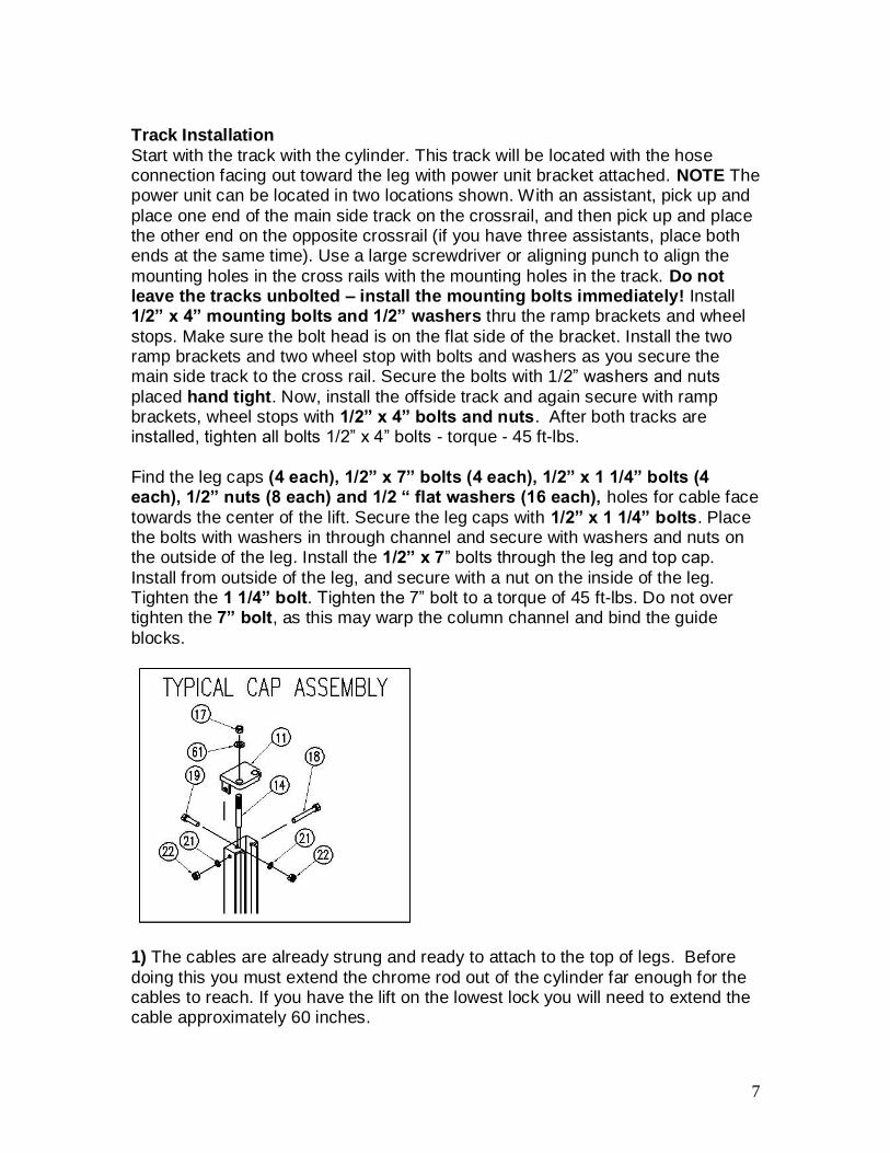
Find the leg caps (4 each), 1/2” x 7” bolts (4 each), 1/2” x 1 1/4” bolts (4 each), 1/2” nuts (8 each) and 1/2 “ flat washers (16 each), holes for cable face
towards the center of the lift. Secure the leg caps with 1/2” x 1 1/4” bolts. Place the bolts with washers in through channel and secure with washers and nuts on the outside of the leg. Install the 1/2” x 7” bolts through the leg and top cap.
Install from outside of the leg, and secure with a nut on the inside of the leg. Tighten the 1 1/4” bolt. Tighten the 7” bolt to a torque of 45 ft-lbs. Do not over tighten the 7” bolt, as this may warp the column channel and bind the guide
blocks.
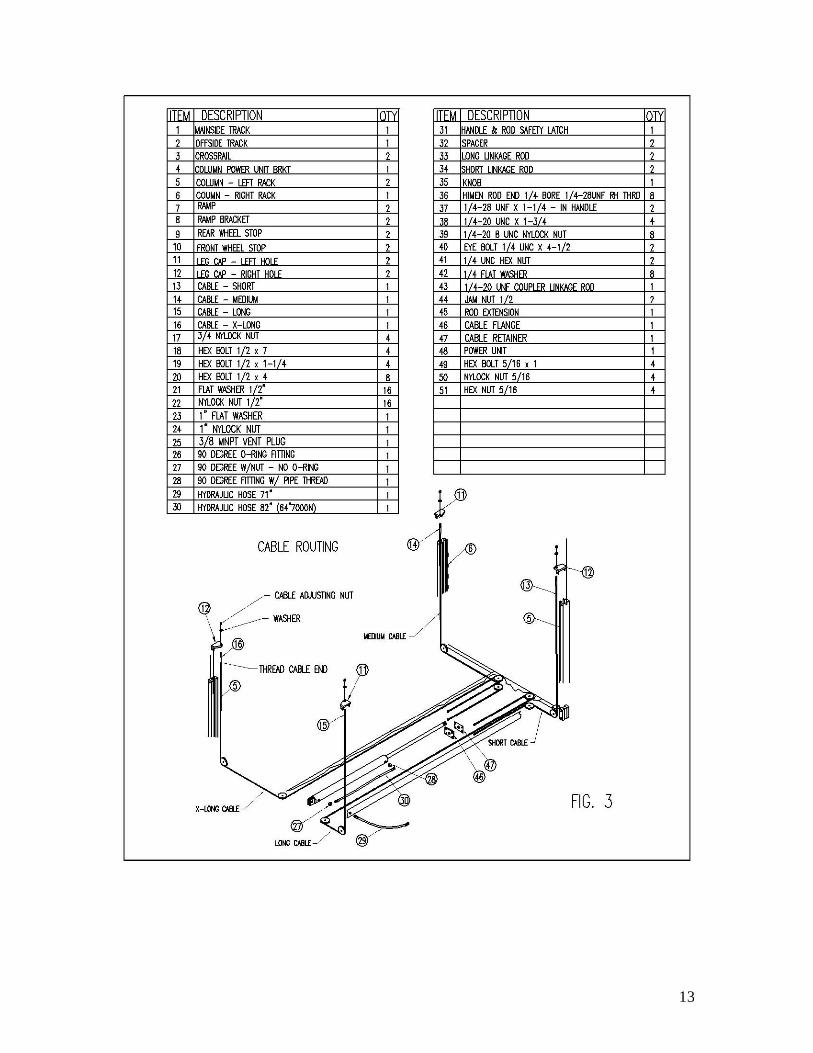
1) The cables are already strung and ready to attach to the top of legs. Before
doing this you must extend the chrome rod out of the cylinder far enough for the cables to reach. If you have the lift on the lowest lock you will need to extend the cable approximately 60 inches.

8
DO NOT USE THE POWER UNIT TO EXTEND THE CYLINDER
Make sure both parts on the cylinder are open to allow the easy flow of air. Manually or with a device such as a come along, pull the cylinder out 60 inches. Although the cylinder may be difficult to move at first, it is usually much easier
once you get the first movement. If you have a compressor you can use air to extend the cylinder. Place the air
Into the back port, (the port away from the chrome rod) and blow air into the cylinder.
After you have extended the chrome rod attach the cable to the top caps in the legs. Make sure each cable is on the pulleys. Place both nuts on top of the top cap and tighten them together.
Safety Latch Linkage Installation: Locate and identify the components needed to install the safety latch linkage rods. Install the spacers from on the straight
threaded end of the 1/2” x 50” (1/2” x 70” for the XLT) bent rod and the threaded end of the 1/2” x 126” straight safety latch linkage rod.
Install the 1/2” x 50” (70” XLT) bent safety latch linkage rod into the main side track adjacent to back end of the cylinder (opposite the cylinder rod). Safety latch linkage rod should pass through guide tubes on underside of track.
Install the 1/2” x 126” straight safety latch linkage rod into the main side track from the opposite end. The rod should pass through two guides on the underside
of the main side track.
Attach the 71” hose to the fitting on the power unit. Attach the other end of the
71” hose to outside fitting in main side track. Attach hose from cylinder to track fitting.
Place a funnel into vent cap hole and fill the tank with one of the following fluids: AW-32 or ISO-32 hydraulic oil. Mobile DTE 24, or Texaco HD 32 DO NOT USE DEXRON® IN THIS LIFT! This tank will hold approximately 12 quarts.
Relocating or changing components may cause problems. Each component in the system must be compatible; an undersized or restricted line will cause a drop
in pressure. All valve, pump, and hose connections should be sealed and/or capped until just before use. All parts should be supplied from manufacture. Air hoses can be used to clean fittings and other components. However, the air
supply must be filtered and dry to prevent contamination. Most important - cleanliness - contamination is the most frequent cause of malfunction or failure of hydraulic equipment.

9
Check Pulley Cover and Lock Collars: Before proceeding, double check to make sure the locking shaft collars for the crossrail cable pulleys are tight and
secure. Check the pulley cover (2-RIGHT and 2 LEFT) over the shaft located on the pulley side of each crossrail. CHECK the pulley and cover are firm against the locking shaft collar already in place. Check the additional lock collar on the
outside of the shaft is tight and secure. To prevent personal injury or death, crossrail lock collars must be tight. If they are ever removed - always make sure the locking shaft collars are tight and secure.
Check the crossrail locking assembly before use. Make sure all bolts and collars are tight. The assembly is pre-installed from the factory but parts
may come loose during shipping. After installation is completed, before start up, be sure to inspect and
tighten all bolts. Start Up: Make sure power unit reservoir is full with 12 quarts of 10-wt hydraulic
oil and spray the inside of the columns where the slide blocks glide with a light lubricant.
2) If you are not familiar with electrical hooks, it is best to call a certified electrician. Check inside the switch box to make sure you use the correct colored wire for ground. Also, check the outside plate to make sure your motor is
the proper voltage. Your motor will be for 110 volts unless you specifically ordered a 220 volt motor.
Initial Operation: Press the UP SWITCH on the power unit. Raise the lift slowly until all the slack in the cables is taken out. Raise the lift until the safety latch closest to the power unit comes within 1” to the bottom of the lowest lock
position. Tighten the cable-adjusting nut on top of each leg cap until all remaining safety latches come within 1” to the bottom of the lowest lock position. If cables are adjusted evenly the lift should be raising level and all four safety latches
engage or audibly click simultaneously. IF LIFT DOES NOT RISE: Check hose connections. Fluid should be pumping
through the hose. Check fluid level. NOTE: There will be some initial stretching of the cables in the beginning. It will
be necessary to readjust the cables a week or so after first use. Run the lift up and down a few times to make sure that the safety latches is
engaging uniformly and that the safety latch release is functioning properly. Re-adjust if necessary.
When lowering the lift PAY CAREFUL ATTENTION. ALWAYS make sure that all FOUR SAFETY LATCHES are disengaged. If one of the latches locks on
10
descent STOP immediately and raise until it is clear of the stop and adjust the hemin on that latch.
Install the approach ramps on the entry side of the lift. Drive a vehicle onto the lift tracks then install the rear wheel chocks. Run the lift up and down a few times to
insure that the latches are engaging uniformly and that the safety latch release is functioning properly. Re-adjust if necessary.
OPERATION Do not use this lift unless you know the proper operation of the lift and its safety devices, and the hazards involved. See Safety Instructions page 2.
1. Drive the vehicle onto lift platform. Set the vehicle’s parking brake and leave the transmission in park / gear. Chock the vehicle’s wheels.
2. Stand clear - Push the top UP button to raise vehicle to desired height. Push the rod handle on the power unit to open release valve and lower tracks until it
stops, check the all four latches for full engagement in the rack on each leg. 3. To lower – push UP button to raise – rotate latch release rod handle and hold -
push rod handle on power unit to lower. Warning: Make sure all four latches release – if not STOP, raise higher until latch is clear, if it does not work now the hemin - tie rod end on that latch needs adjustment.
4. Any hydraulic oil leakage, unusual noise, or excessive wear must be fixed before using lift.
PRE OPERATION CHECK The user should perform daily check. ATTENTION! LOOK OUT! Daily check of safety latch system is very important - the discovery of device failure before needed could save you from expensive property damage, lost production time, serious personal injury and even death. 1. Check safety latches for free movement and full engagement with rack. 2. Check hydraulic connections, and hoses for leakage. 3. Check cables for damage and that they are in the groove on cable sheave. 4. Check lock collars at all rollers and sheaves. 5. Check bolts, nuts, and screws and tighten. 6. Check wiring & switches for damage. 7. Keep base plate free of dirt, grease or any other corrosive substances.

11

12
13