nstx experimental proposal - op-xp-825 title: hhfw heating/cd phase scans in d l-mode plasmas p....
TRANSCRIPT

NSTX EXPERIMENTAL PROPOSAL - OP-XP-825 Title: HHFW Heating/CD phase scans in D L-mode plasmas
P. Ryan, J. Hosea, R. Bell, L. Delgado-Aparicio, S. Kubota, B. LeBlanc, F. Levinton, C.K. Phillips, S. Sabbagh, G. Taylor, K. Tritz, J. Wilgen, J.R. Wilson, et al.
ET – Wave Physics
1. Objectives of the experiment:
Heating in D2 L mode:• Determine if density can be kept low enough to prevent wave propagation near wall• Show how efficiency depends on wavelength in deuterium • Need to establish behavior in deuterium L mode to optimize current drive for startup and in preparation for H mode studies
CD in D2 L mode:1. Phase scan for HHFW CD with time-resolved MSE
Use conditions of shots 107899 and 107907 (at 5.5 kG) if required to show loop voltage change
• MSE beam blip at end of HHFW pulse and progressively move it forward in time upon succeeding shots to determine the current relaxation time
• Determine the effect of co-, cntr-CD, and heating on stability of NBI-driven plasmas.
2
Heating and CD in D2 L mode
2. Theoretical/ empirical justification• This XP is a continuation of XPs 712 and 717 which established
HHFW heating efficiency and CD properties in helium L mode plasmas
• Properties in deuterium are to be determined and compared to helium properties and analyzed with advanced RF modeling codes
• Need to establish behavior in deuterium L mode to optimize current drive for startup and in preparation for H mode studies
• Need increased power (3-4 MW) to improve the MSE CD measurement.

Edge density appears to affect the heating when it is above the onset density close to the antenna
• How does efficiency depend on wavelength in deuterium? (XP712 rev)
Helium plasma results
• Can density be held below onset value in deuterium?
Helium plasma results

Phase scan needed for deuterium case
Phase scan illuminates decrease in heating efficiency at longer wavelength and permits MSE measurements of CD
• Results in helium suggest movement of onset density to antenna/wall causes losses rather than lack of cancellation of reactive currents• Need D2 scan to provide data set for comparing to helium case
5
7
6
5
4
3
2
1
0-20 -10 0 10 20
kz(m-1)
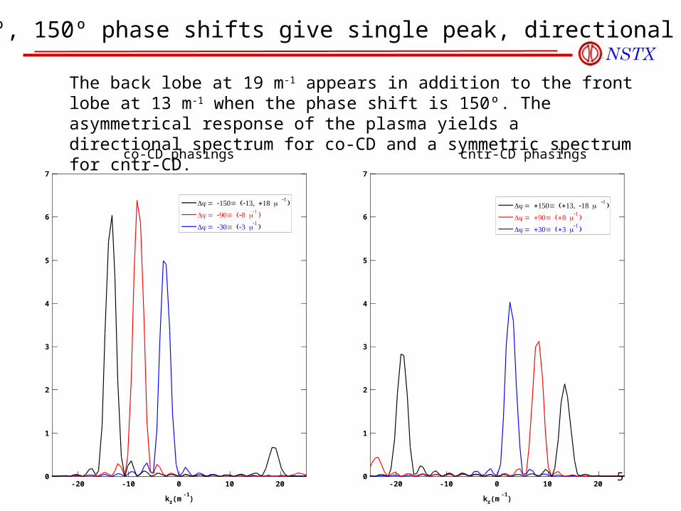
Δφ = -150 (-13, +18 º m-1 )
Δφ = -90 (-8 º m-1 )
Δφ = -30 (-3 º m-1 )
7
6
5
4
3
2
1
0-20 -10 0 10 20
kz(m-1)
Δφ = +150 (+13, -18 º m-1 )
Δφ = +90 (+8 º m-1 )
Δφ = +30 (+3 º m-1 )
co-CD phasings cntr-CD phasings
The back lobe at 19 m-1 appears in addition to the front lobe at 13 m-1 when the phase shift is 150º. The asymmetrical response of the plasma yields a directional spectrum for co-CD and a symmetric spectrum for cntr-CD.
30º, 90º, 150º phase shifts give single peak, directional spectra
6
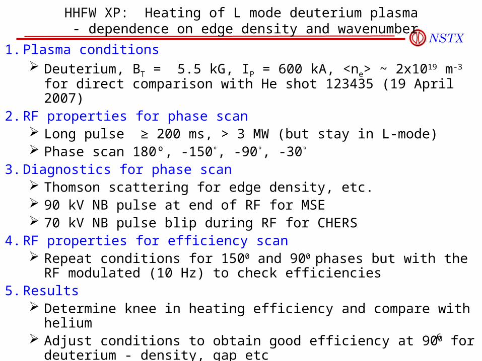
HHFW XP: Heating of L mode deuterium plasma - dependence on edge density and wavenumber
1. Plasma conditions Deuterium, BT = 5.5 kG, IP = 600 kA, <ne> ~ 2x10¹⁹ m-3 for direct
comparison with He shot 123435 (19 April 2007)2. RF properties for phase scan
Long pulse ≥ 200 ms, > 3 MW (but stay in L-mode) Phase scan 180º, -150º, -90º, -30º
3. Diagnostics for phase scan Thomson scattering for edge density, etc. 90 kV NB pulse at end of RF for MSE 70 kV NB pulse blip during RF for CHERS
4. RF properties for efficiency scan Repeat conditions for 1500 and 900 phases but with the RF modulated
(10 Hz) to check efficiencies 5. Results
Determine knee in heating efficiency and compare with helium Adjust conditions to obtain good efficiency at 900 for deuterium - density,
gap etc

7
Phase scan for HHFW CD with time-resolved MSE
1. Plasma conditions Continue conditions from heating phase, but may need to reduce density
to increase CD efficiency. This may involve using outer gas feeds so that gas may be turned off
before RF comes on (check during XMP26 conditioning day)
2. RF Properties Same power and pulse length as phase 1.
3. Diagnostics Start MSE beam at end of HHFW pulse and progressively move it
forward in time upon succeeding shots to determine the current relaxation time (3 steps).
Observe effect of HHFW/NBI on plasma stability as a function of phase.
4. Phase scan Run -90º, +90º (-30º, +30º, if time permits) If time, phase transition from -90º to -30º(-8 to -3 m-1); two beam blips
before transition, two after (4 additional shots).

8
Previous CD measurements in D2 made at lower density than last year’s MSE measurements in He
D2 CD, April 19, 20024.5 kG
He CD, April 19, 20075.5 kG, MSE

Heating and CD in D2 L mode
3. Experimental run plan -- 1 day of run time
Setup conditions as for XP712 at B = 5.5 kG but with deuterium plasma:3. LSN, deuterium L-mode, gap ~ 4 - 5 cm (same conditions as for shot 123435, -90 degrees)
4. Apply PRF as for ~ 200 ms (at full 0.55 Tesla field) with k || = -8m-1
5. Apply 90 kV NB pulse at end of RF pulse - use 70 kV beam to measure T i and rotation
3 shots
A Perform wavenumber scan at ~ 4 cm Scan vs phase is limited by need to complete it in 1/2 day
• With plasma settings as for shot 123435 but with deuterium - Gap at ~ 4 cm:
• 1 shot @ 14 m-1 (180o)
• 1 shot @ -13 m-1 (-150o)
• 1 shot @ -8 m-1 (-90o)
• 1 shot @ -3 m-1 (-30o)
• 1 no RF shot
(Additional shots may be required to set matching for each k ||. NB should be added 20 ms before end of RF pulse)
10
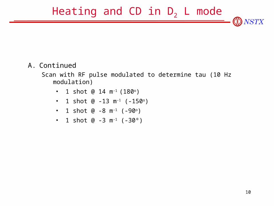
Heating and CD in D2 L mode
A. ContinuedScan with RF pulse modulated to determine tau (10 Hz modulation)
• 1 shot @ 14 m-1 (180o)
• 1 shot @ -13 m-1 (-150o)
• 1 shot @ -8 m-1 (-90o)
• 1 shot @ -3 m-1 (-30º)
11
Heating and CD in D2 L mode
B Phase scan for HHFW CD with time-resolved MSE
With NB pulse near end of RF pulse:
• 1 shot @ 14 m-1 (180o)
• 1 shot @ -8 m-1 (-90o)
• 1 shot @ +8 m-1 (+90o) Check that voltage is responding to phase. If not change
conditions
With NB stepped in toward start of RF pulse
• 2 shots @ +8 m-1 (+90o)
• 2 shot @ -8 m-1 (-90o)
• 1 no RF shot
(Additional shots may be required to set matching for each k ||.)

12
B Continued
Put on long NB pulse and see if reaction depends on phase• 1 shot @ -8 m-1 (-90o)
• 1 shot @ +8 m-1 (+90o)
• 1 shot @ 14 m-1 (180o)
These shots are intended to see if we can drive current (or even operate) in the presence of high power NBI. May also go into H-mode. May need to go to 70 kV beams.
Some of this may be accomplished during the time-resolved MSE measurements.
Heating and CD in D2 L mode

13
Example of Time-Resolved MSE Measurements
1st2nd3rd
90 kV NB
Ip (0.6 MA)
3+ MW HHFW
0 .18 .48.45.35.25
30 ms beam blip positioned at the end of the RF pulseIncrement beam turn-on time by 100 ms on succeeding shotsEstablish CD relaxation time and HHFW/NBI stability as a function of phase.
14
Heating and CD in D2 L mode
4. Required machine, NBI, RF, CHI and diagnostic capabilitiesStable or at least reproducible plasma conditions are required for the quantitative comparisons of this XP. Critical diagnostics include:
• Soft x-ray and Mirnov loops for stability• EFIT with high time resolution for • Thomson scattering for electrons• Edge rotation diagnostic for edge heating• NPA for edge and core ion heating• Radiated power diagnostic• Reflectometry for edge density and PDI• Reflectometry for wave measurements for opposite side from antenna• Edge probe for PDI• Gap RF probes for leakage• 3 RF probe(s) for edge RF field
• CHERS for some shots for Ti and velocities• MSE for as required for determining effects on current• NB pulses needed at 90 kV and 70 kV
15
Heating and CD in D2 L mode
5. Expected results and planned analysisExpected results:
• Heating efficiency in deuterium L mode vs wavenumber: 14 m-1, -8 m-1 (co CD), -3 m-1, -13 m-1, etc.– Core heating from EFIT W
– Core electron heating from Thomson scattering
– Ion heating and core rotation from Chers
• Edge heating/power loss – Edge ion heating from edge rotation diagnostic
– Edge electron heating from Thomson scattering
– Rotation effects
• MSE measurements of current drive– Co vs counter for conditions where loop voltage is reduced for co
5. Loop voltage difference for co/cntr, compare to MSE
6. Plasma profiles, core and edge, for permitting predictions of wave propagation damping and CD characteristics

16
Heating and CD in D2 L mode
Planned analysis:
• Compare power coupling efficiencies vs wavenumber to those for helium
• Determine CD profile vs time in RF pulse, CD efficiency and compare with RF code predictions.
• Determine if stability with NB is dependent on antenna phase
• Analysis of wave propagation, damping and CD characteristics from onset density into the core of plasma - along field and perpendicular directions of the ray path, and including collisions - for predicting CD and surface losses
• Benchmarking of RF codes that include surface losses

17
RF Power Flow and Possible Loss Channels
Mode conversion at nci
Ion absorption at nci
Landau damping on
core electrons
AN
TE
NN
A
Evanescent waves(local sheaths,
collisional heating)
IBW waves,surface waves,
PDI
Non-absorbed(Far-field sheaths,
wall heating)
HHFW PowerRF Power
Shots analyzed107899 (co-CD)107907 (cntr-CD)
GLOSI/RANT3D (propagating FW calculation)<RL>(co-CD) = 16.2 <RL>(cntr-CD) = 8.2
Measurement<RL>(co-CD) = 19.3 <RL>(cntr-CD) = 7.9
Loading calculations agree with measurements to within 20% for co-CD, 5% for cntr-CD
5-20%? ~ 25% ??
~35-55% co~50-70% cntr
< 5%