nt, nshd,nb & dv
TRANSCRIPT

NT, NSHD,NB & DVEND-SUCTION CENTRIFUGAL PUMPS TO EN733 (DIN 24255)

Version 1 - NT, NSHD & NB: Rapid Allweiler PumpsWhilst all care has been taken to ensure the accuracy of the information contained in this brochure was correct at the time of printing, please be advised we cannot be held responsible for any errors contained within and or changes that may have taken place. Dimensions contained within are for reference purpose only and should not be used for construction; certified drawings are available upon request. For confirmation of any information contained herewith please contact a member of our technical sales team.
DEEP APPLICATION KNOWLEDGE
TAILOR MADE PUMPING SOLUTIONS
STATE OF THE ART TRAINING CENTRE
LEADING PROVIDER OF TOP QUALITY PRODUCTS
LOCAL MANUFACTURE
FOUNDED IN 1932
OWN FOUNDRY
ACCREDITED PUMP REPAIR/SERVICE WORKSHOP
ISO 9001:2008
BEE ACCREDITED
AFTER MARKET SERVICE
WE HAVE ALL THE TICKS
FOUNDER A J HINDRY
RAPID ALLWEILER PUMPS HEAD OFFICE
OWN WORKSHOP
OWN FOUNDRY
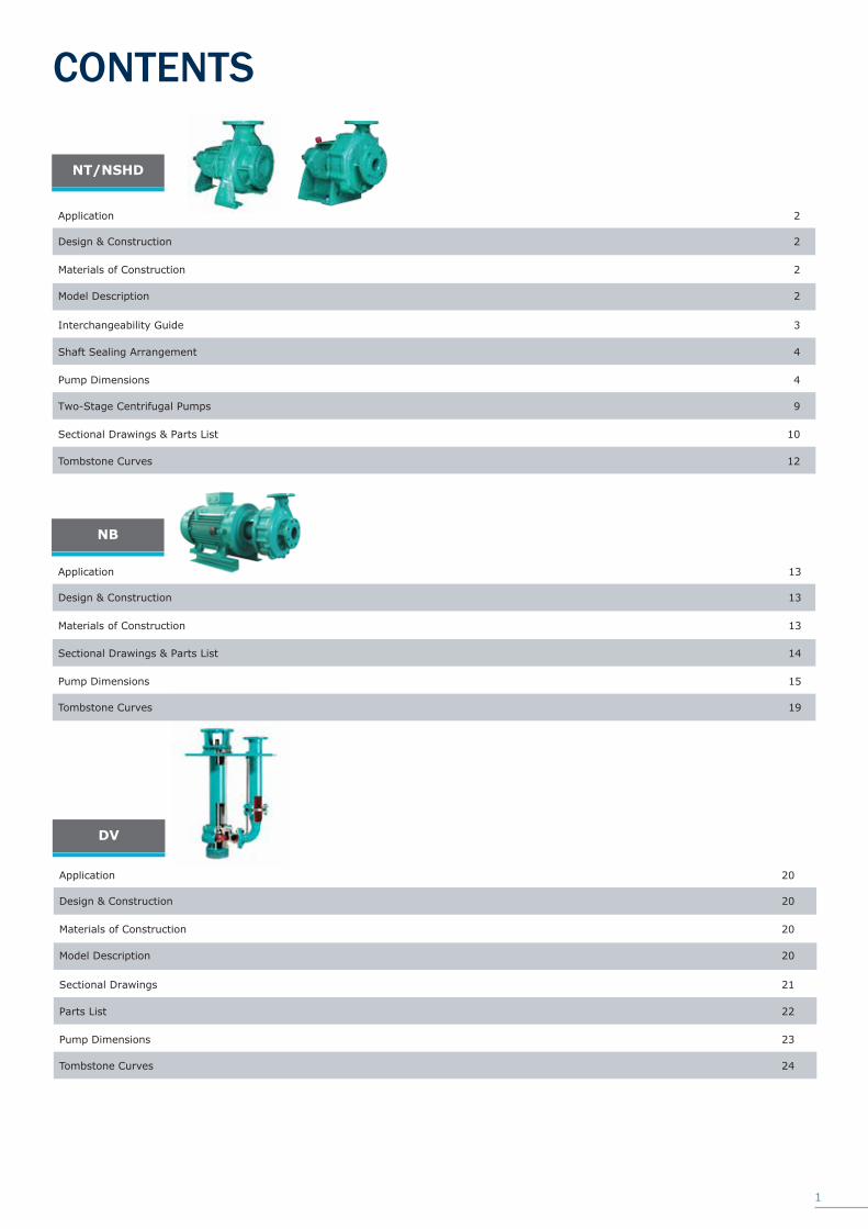
DV
Parts List
Application
Tombstone Curves
Pump Dimensions
Sectional Drawings
Design & Construction
Materials of Construction
Model Description
22
20
24
23
21
20
20
20
1
NT/NSHD
NB
Shaft Sealing Arrangement
Application
Two-Stage Centrifugal Pumps
Pump Dimensions
Tombstone Curves
Interchangeability Guide
Sectional Drawings & Parts List
Design & Construction
Materials of Construction
CONTENTS
Model Description
4
2
9
4
12
3
10
2
2
2
Application
Pump Dimensions
Tombstone Curves
Sectional Drawings & Parts List
Design & Construction
Materials of Construction
13
15
19
14
13
13
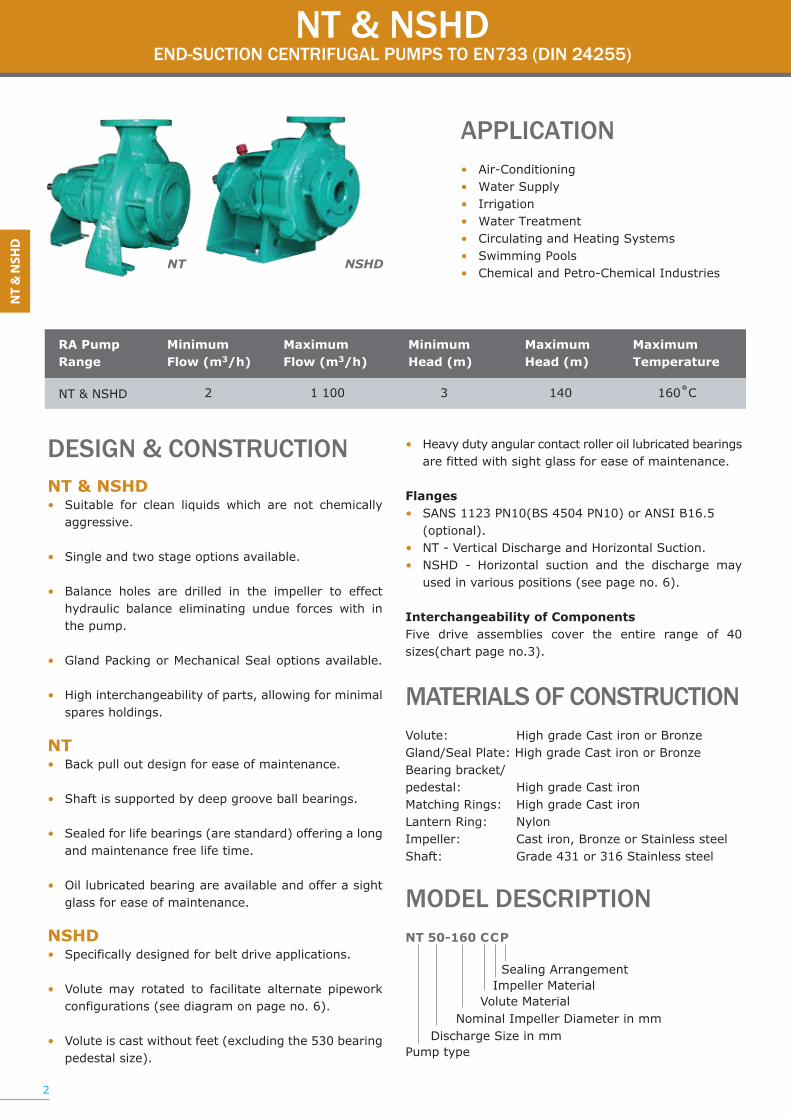
NT & NSHDEND-SUCTION CENTRIFUGAL PUMPS TO EN733 (DIN 24255)
NT & NSHDEND-SUCTION CENTRIFUGAL PUMPS TO EN733 (DIN 24255)
RA Pump Range
Minimum Flow (m3/h)
Maximum Flow (m3/h)
Minimum Head (m)
Maximum Head (m)
Maximum Temperature
NT & NSHD 2 1 100 3 140 160˚C
APPLICATION• Air-Conditioning• Water Supply• Irrigation• Water Treatment• Circulating and Heating Systems• Swimming Pools• Chemical and Petro-Chemical Industries
NT NSHD
2
DESIGN & CONSTRUCTION NT & NSHD• Suitable for clean liquids which are not chemically aggressive. • Single and two stage options available. • Balance holes are drilled in the impeller to effect hydraulic balance eliminating undue forces with in the pump. • Gland Packing or Mechanical Seal options available.
• High interchangeability of parts, allowing for minimal spares holdings. NT• Back pull out design for ease of maintenance.
• Shaft is supported by deep groove ball bearings.
• Sealed for life bearings (are standard) offering a long and maintenance free life time.
• Oil lubricated bearing are available and offer a sight glass for ease of maintenance.
NSHD• Specifically designed for belt drive applications.
• Volute may rotated to facilitate alternate pipework configurations (see diagram on page no. 6).
• Volute is cast without feet (excluding the 530 bearing pedestal size).
• Heavy duty angular contact roller oil lubricated bearings are fitted with sight glass for ease of maintenance.
Flanges• SANS 1123 PN10(BS 4504 PN10) or ANSI B16.5 (optional). • NT - Vertical Discharge and Horizontal Suction.• NSHD - Horizontal suction and the discharge may used in various positions (see page no. 6).
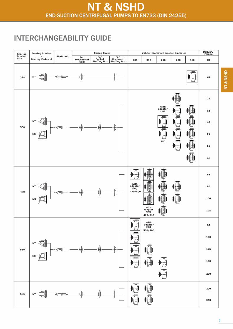
Interchangeability of ComponentsFive drive assemblies cover the entire range of 40 sizes(chart page no.3).
MATERIALS OF CONSTRUCTIONVolute: High grade Cast iron or BronzeGland/Seal Plate: High grade Cast iron or BronzeBearing bracket/pedestal: High grade Cast ironMatching Rings: High grade Cast ironLantern Ring: NylonImpeller: Cast iron, Bronze or Stainless steelShaft: Grade 431 or 316 Stainless steel
MODEL DESCRIPTIONNT 50-160 CCP Sealing Arrangement Impeller Material Volute Material Nominal Impeller Diameter in mm Discharge Size in mmPump type
NT & NSHDEND-SUCTION CENTRIFUGAL PUMPS TO EN733 (DIN 24255)
INTERCHANGEABILITY GUIDE
3
Bearing Bracketor
Bearing PedestalShaft unit
Casing Cover Volute - Nominal Impeller Diameter Delivery Flange
ID
BearingBracketSize
withadaptor
ring
withadaptor
ring
withadaptor
ring
250
470/400
withadaptor
ring470/315
530/400
For Mechanical
Seal400
25228
360
470
530
585
NT
NT
NT
NT
NT
NS
25
32
40
50
65
80
65
80
80
100
100
125
150
200
200
250
125
315 250 200 160For
Cooled Stuffing Box
For Uncooled
Stuffing Box
NS
NS

SHAFT SEALING ARRANGEMENT - SINGLE STAGE
Gland packing withlantern ring
Gland packing withoutlantern ring
Gland packing withexternal flush
Mechanical seal
NT & NSHDEND-SUCTION CENTRIFUGAL PUMPS TO EN733 (DIN 24255)
201GNISAC ETULOV
1.161ETALP DNALG
2.161ETALP LAES
112TFAHS
032RELLEPMI
033TEKCARB GNIRAEB
233LATSEDEP GNIRAEB
254DNALG
854GNIR NRETNAL
1.074LAES LACINAHCEM
PUMP DIMENSIONSNT
Size 250-400 only.
585 Foot
(1) 200mm
(2) 160mm
(3) 12mm
(4) M16
4
230 33-01 332102 400-2 161-1 458 452211161-1 161-1 161-1 470-1

NB. The “ * ” refers to additional pumps which sizes are not included in DIN 24255
Size
Dis
char
ge F
lang
e
Suct
ion
Flan
ge
snoisnemiD tooFsnoisnemiD pmuP
Dis
man
tling
Spa
ce
Bol
ts
Shaft endacc. to DIN
42946
Filli
ng H
ole
Dra
inag
e
Leak
age
wat
erC
onne
ctio
n
Gau
ge C
onne
ctio
n
Gau
ge C
onne
ctio
n
Con
nect
ion
for
Stuf
fing
Box
Coo
ling
Fore
ign
Seal
ing
Con
nect
ion
IDd IDs a f h1 h2 b1 b2 b c h3 i m1 m2 m3 n1 n2 w x s d l t u A B D M1 M2 K S
25-160 25 25 63 243 112 160 100 108 50 12 112 - 100 70 - 220 180 - 60 M10 17 41 19 5 R1/4” R1/4” R1/4” R1/4” R1/4” R1/8” R1/8”
25-200 25 40 80 360 160 180 132 132 50 15 160 28 100 70 50 240 190 260 80 M12 24 50 27 8 R1/4” R1/4” R1/4” R1/4” R1/4” R1/4” R1/8”
32-160 32 50 80 360 132 160 123 123 50 15 132 28 100 70 50 240 190 260 80 M12 24 50 27 8 R1/4” R1/4” R3/8” R1/4” R1/4” R1/4” R1/8”
32-200 32 50 80 360 160 180 124 130 50 15 160 28 100 70 50 240 190 260 80 M12 24 50 27 8 R1/4” R1/4” R3/8” R1/4” R1/4” R1/4” R1/8”
40-160 40 65 80 360 132 160 123 123 50 15 132 28 100 70 50 240 190 260 80 M12 24 50 27 8 R1/4” R1/4” R3/8” R1/4” R1/4” R1/4” R1/8”
40-200 40 65 100 360 160 180 125 135 50 15 160 28 100 70 50 265 212 265 80 M12 24 50 27 8 R1/4” R1/4” R3/8” R1/4” R1/4” R1/4” R1/8”
40-250 40 65 100 360 180 225 150 156 65 15 180 28 125 95 50 320 250 265 80 M12 24 50 27 8 R1/4” R1/4” R3/8” R1/4” R1/4” R1/4” R1/8”
50-160 50 65 100 360 160 180 125 130 50 15 160 28 100 70 50 265 212 260 80 M12 24 50 27 8 R1/4” R1/4” R3/8” R1/4” R1/4” R1/4” R1/8”
50-200 50 65 100 360 160 200 133 145 50 15 160 28 100 70 50 265 212 265 80 M12 24 50 27 8 R1/4” R1/4” R3/8” R1/4” R1/4” R1/4” R1/8”
50-250 50 65 100 360 180 225 156 169 65 15 180 28 125 95 50 320 250 265 80 M12 24 50 27 8 R1/4” R1/4” R3/8” R1/4” R1/4” R1/4” R1/8”
65-160 65 80 100 360 160 200 133 162 65 15 160 28 125 95 50 280 212 265 80 M12 24 50 27 8 R1/4” R1/4” R3/8” R1/4” R1/4” R1/4” R1/8”
65-200 65 80 100 360 180 225 148 170 65 15 180 28 125 95 50 320 250 265 100 M12 24 50 27 8 R1/4” R1/4” R3/8” R1/4” R1/4” R1/4” R1/8”
65-250 65 80 100 470 200 250 164 184 80 18 200 28 160 120 50 360 280 340 100 M16 32 80 35 10 R3/8” R3/8” R3/8” R3/8” R1/4” R1/4” R1/8”
65-315 65 80 125 470 225 280 202 211 80 25 225 28 160 120 50 400 315 340 100 M16 32 80 35 10 R3/8” R3/8” R3/8” R3/8” R1/4” R1/4” R1/8”
65-400 65 80 125 470 250 355 239 255 80 25 250 28 160 120 50 420 335 340 100 M16 32 80 35 10 R3/8” R3/8” R3/8” R3/8” R1/4” R1/4” R1/8”
80-160 80 100 125 360 180 225 136 170 65 15 180 28 125 95 50 320 250 265 100 M12 24 50 27 8 R1/4” R1/4” R3/8” R1/4” R1/4” R1/4” R1/8
80-200 80 100 125 470 180 250 163 188 65 18 180 28 125 95 50 345 280 340 100 M12 32 80 35 10 R3/8” R3/8” R3/8” R3/8” R1/4” R1/4” R1/8”
80-250 80 100 125 470 200 280 182 208 80 18 200 28 160 120 50 400 315 340 100 M16 32 80 35 10 R3/8” R3/8” R3/8” R3/8” R1/4” R1/4” R1/8”
80-315 80 100 125 470 250 315 210 231 80 25 250 28 160 120 50 400 315 340 100 M16 32 80 35 10 R3/8” R3/8” R3/8” R3/8” R1/4” R1/4” R1/8”
80-400 80 100 125 530 280 355 246 265 80 25 280 28 160 120 50 435 355 370 140 M16 42 110 45 12 R3/8” R3/8” R3/8” R3/8” R1/4” R1/4” R1/4”
100-200 100 125 125 470 200 280 165 203 80 18 200 28 160 120 50 360 280 340 120 M16 32 80 35 10 R3/8” R3/8” R3/8” R3/8” R1/4” R1/4” R1/8”
100-250 100 125 140 470 225 280 189 224 80 18 225 28 160 120 50 400 315 340 120 M16 32 80 35 10 R3/8” R3/8” R3/8” R3/8” R1/4” R1/4” R1/8”
100-315 100 125 140 470 250 315 220 250 80 25 250 28 160 120 50 400 315 340 120 M16 32 80 35 10 R3/8” R3/8” R3/8” R3/8” R1/4” R1/4” R1/8”
100-400 100 125 140 530 280 355 256 272 100 27 280 28 200 150 50 500 400 370 140 M20 42 110 45 12 R3/8” R3/8” R3/8” R3/8” R1/4” R1/4” R1/4”
125-250 125 150 140 470 250 355 212 255 80 18 250 28 160 120 50 400 315 340 120 M16 32 80 35 10 R3/8” R3/8” R3/8” R3/8” R1/4” R1/4” R1/8”
125-315 125 150 140 530 280 355 226 252 100 27 280 28 200 150 50 500 400 370 140 M20 42 110 45 12 R3/8” R3/8” R3/8” R3/8” R1/4” R1/4” R1/4”
125-400 125 150 140 530 315 400 264 283 100 27 315 28 200 150 50 500 400 370 140 M20 42 110 45 12 R3/8” R3/8” R3/8” R3/8” R1/4” R1/4” R1/4”
150-250 150 200 160 530 280 375 231 283 100 27 280 28 200 150 50 500 400 370 140 M20 42 110 45 12 R3/8” R3/8” R3/8” R3/8” R1/4” R1/4” R1/4”
150-315 150 200 160 530 280 400 239 271 100 27 280 28 200 150 50 550 450 370 140 M20 42 110 45 12 R3/8” R3/8” R3/8” R3/8” R1/4” R1/4” R1/4”
150-400/1 150 200 160 530 315 450 277 305 100 27 315 28 200 150 50 550 450 370 140 M20 42 110 45 12 R3/8” R3/8” R3/8” R3/8” R1/4” R1/4” R1/4”
200-250 200 200 180 530 355 425 262 330 100 27 355 28 200 150 50 550 450 370 140 M20 42 110 45 12 R3/8” R3/8” R3/8” R3/8” R1/4” R1/4” R1/4”
200-315 200 250 200 585 355 450 270 335 110 27 355 37 200 150 65 550 450 420 180 M20 60 105 64 18 R3/8” R3/8” R3/8” R3/8” R1/4” R1/4” R1/4”
200-400 200 250 180 585 355 500 315 374 100 30 355 37 200 150 65 550 450 420 180 M20 60 105 64 18 R3/8” R3/8” R3/8” R3/8” R1/4” R1/4” R1/4”
250-315 250 300 250 585 400 560 325 408 130 30 400 37 260 190 65 690 560 420 180 M24 60 105 64 18 R3/8” R3/8” R3/8” R3/8” R1/4” R1/4” R1/4”
250-400 250 300 225 585 375 625 350 440 120 30 400 37 280 200 65 630 500 420 180 M27 60 105 64 18 R3/8” R3/8” R3/8” R3/8” R1/4” R1/4” R1/4”
PUMP DIMENSIONSNT SERIES
NT & NSHDEND-SUCTION CENTRIFUGAL PUMPS TO EN733 (DIN 24255)
Flange up to ID 150 acc. toDIN 2533 from ID 200 onwards
acc. to DIN 2532
No. of
IDd Holes
25 115 16 85 14 4
32 140 18 100 18 4
40 150 18 110 18 4
50 165 20 125 18 4
65 185 20 145 18 4
80 200 22 160 18 8
100 220 24 180 18 8
125 250 26 210 18 8
150 285 26 240 22 8
200 340 26 295 22 12
250 395 28 350 22 12
300 445 28 400 22 125

DESIGN & CONSTRUCTION NT & NSHD• Suitable for clean liquids which are not chemically aggressive. • Single and two stage options available. • Balance holes are drilled in the impeller to effect hydraulic balance eliminating undue forces with in the pump. • Gland Packing or Mechanical Seal options available.
• High interchangeability of parts, allowing for minimal spares holdings. NT• Back pull out design for ease of maintenance.
• Shaft is supported by deep groove ball bearings.
• Sealed for life bearings (are standard) offering a long and maintenance free life time.
• Oil lubricated bearing are available and offer a sight glass for ease of maintenance.
NSHD• Specifically designed for belt drive applications.
• Volute may rotated to facilitate alternate pipework configurations (see diagram on page no. 6).
• Volute is cast without feet (excluding the 530 bearing pedestal size).
• Heavy duty angular contact roller oil lubricated bearings are fitted with sight glass for ease of maintenance.
Flanges• SANS 1123 PN10(BS 4504 PN10) or ANSI B16.5 (optional). • NT - Vertical Discharge and Horizontal Suction.• NSHD - Horizontal suction and the discharge may used in various positions (see page no. 6).
Interchangeability of ComponentsFive drive assemblies cover the entire range of 40 sizes(chart page no.3).
MATERIALS OF CONSTRUCTIONVolute: High grade Cast iron or BronzeGland/Seal Plate: High grade Cast iron or BronzeBearing bracket/pedestal: High grade Cast ironMatching Rings: High grade Cast ironLantern Ring: NylonImpeller: Cast iron, Bronze or Stainless steelShaft: Grade 431 or 316 Stainless steel
MODEL DESCRIPTIONNT 50-160 CCP Sealing Arrangement Impeller Material Volute Material Nominal Impeller Diameter in mm Discharge Size in mmPump type
NT & NSHDEND-SUCTION CENTRIFUGAL PUMPS TO EN733 (DIN 24255)
BRANCH POSITION (Seen on suction branch)
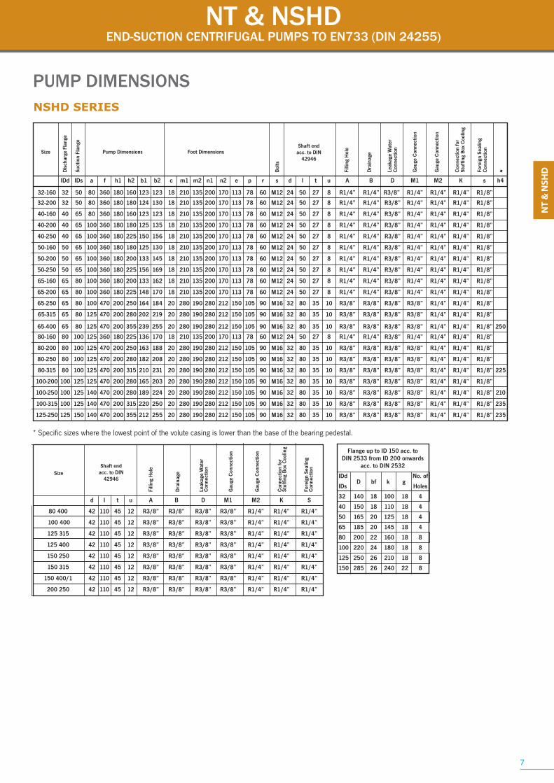
PUMP DIMENSIONS
NSHD SERIES
NSHD SERIES - WITH BEARING PEDESTAL SIZES 360 & 470
Bearing pedestal size 360
Note:
3L, 3R, 4L and 4R imply an alteration of the bolt hole positions on the suction flange and requires flange on pipe
work to be adjusted accordingly.
Bearing pedestal size 470
6
45˚ 45˚90˚ 90˚
1L 2L 2Rstandard 1R
30˚ 30˚ 60˚ 60˚90˚ 90˚
3L 3R 4L 4R 5L 5Rstandard
NT & NSHDEND-SUCTION CENTRIFUGAL PUMPS TO EN733 (DIN 24255)
Size
Dis
char
ge F
lang
e
Suct
ion
Flan
ge
snoisnemiD tooFsnoisnemiD pmuP
Bol
ts
Shaft endacc. to DIN
42946
Filli
ng H
ole
Dra
inag
e
Leak
age
Wat
erC
onne
ctio
n
Gau
ge C
onne
ctio
n
Gau
ge C
onne
ctio
n
Con
nect
ion
for
Stuf
fing
Box
Coo
ling
Fore
ign
Seal
ing
Con
nect
ion
IDd IDs a f h1 h2 b1 b2 c m1 m2 n1 n2 e p r s d l t u A B D M1 M2 K s h4
32-160 32 50 80 360 180 160 123 123 18 210 135 200 170 113 78 60 M12 24 50 27 8 R1/4” R1/4” R3/8” R1/4” R1/4” R1/4” R1/8”
32-200 32 50 80 360 180 180 124 130 18 210 135 200 170 113 78 60 M12 24 50 27 8 R1/4” R1/4” R3/8” R1/4” R1/4” R1/4” R1/8”
40-160 40 65 80 360 180 160 123 123 18 210 135 200 170 113 78 60 M12 24 50 27 8 R1/4” R1/4” R3/8” R1/4” R1/4” R1/4” R1/8”
40-200 40 65 100 360 180 180 125 135 18 210 135 200 170 113 78 60 M12 24 50 27 8 R1/4” R1/4” R3/8” R1/4” R1/4” R1/4” R1/8”
40-250 40 65 100 360 180 225 150 156 18 210 135 200 170 113 78 60 M12 24 50 27 8 R1/4” R1/4” R3/8” R1/4” R1/4” R1/4” R1/8”
50-160 50 65 100 360 180 180 125 130 18 210 135 200 170 113 78 60 M12 24 50 27 8 R1/4” R1/4” R3/8” R1/4” R1/4” R1/4” R1/8”
50-200 50 65 100 360 180 200 133 145 18 210 135 200 170 113 78 60 M12 24 50 27 8 R1/4” R1/4” R3/8” R1/4” R1/4” R1/4” R1/8”
50-250 50 65 100 360 180 225 156 169 18 210 135 200 170 113 78 60 M12 24 50 27 8 R1/4” R1/4” R3/8” R1/4” R1/4” R1/4” R1/8”
65-160 65 80 100 360 180 200 133 162 18 210 135 200 170 113 78 60 M12 24 50 27 8 R1/4” R1/4” R3/8” R1/4” R1/4” R1/4” R1/8”
65-200 65 80 100 360 180 225 148 170 18 210 135 200 170 113 78 60 M12 24 50 27 8 R1/4” R1/4” R3/8” R1/4” R1/4” R1/4” R1/8”
65-250 65 80 100 470 200 250 164 184 20 280 190 280 212 150 105 90 M16 32 80 35 10 R3/8” R3/8” R3/8” R3/8” R1/4” R1/4” R1/8”
65-315 65 80 125 470 200 280 202 219 20 280 190 280 212 150 105 90 M16 32 80 35 10 R3/8” R3/8” R3/8” R3/8” R1/4” R1/4” R1/8”
65-400 65 80 125 470 200 355 239 255 20 280 190 280 212 150 105 90 M16 32 80 35 10 R3/8” R3/8” R3/8” R3/8” R1/4” R1/4” R1/8” 250
80-160 80 100 125 360 180 225 136 170 18 210 135 200 170 113 78 60 M12 24 50 27 8 R1/4” R1/4” R3/8” R1/4” R1/4” R1/4” R1/8”
80-200 80 100 125 470 200 250 163 188 20 280 190 280 212 150 105 90 M16 32 80 35 10 R3/8” R3/8” R3/8” R3/8” R1/4” R1/4” R1/8”
80-250 80 100 125 470 200 280 182 208 20 280 190 280 212 150 105 90 M16 32 80 35 10 R3/8” R3/8” R3/8” R3/8” R1/4” R1/4” R1/8”
80-315 80 100 125 470 200 315 210 231 20 280 190 280 212 150 105 90 M16 32 80 35 10 R3/8” R3/8” R3/8” R3/8” R1/4” R1/4” R1/8” 225
100-200 100 125 125 470 200 280 165 203 20 280 190 280 212 150 105 90 M16 32 80 35 10 R3/8” R3/8” R3/8” R3/8” R1/4” R1/4” R1/8”
100-250 100 125 140 470 200 280 189 224 20 280 190 280 212 150 105 90 M16 32 80 35 10 R3/8” R3/8” R3/8” R3/8” R1/4” R1/4” R1/8” 210
100-315 100 125 140 470 200 315 220 250 20 280 190 280 212 150 105 90 M16 32 80 35 10 R3/8” R3/8” R3/8” R3/8” R1/4” R1/4” R1/8” 235
125-250 125 150 140 470 200 355 212 255 20 280 190 280 212 150 105 90 M16 32 80 35 10 R3/8” R3/8” R3/8” R3/8” R1/4” R1/4” R1/8” 235
Flange up to ID 150 acc. toDIN 2533 from ID 200 onwards
acc. to DIN 2532
seloHsDI
32 140 18 100 18 4
40 150 18 110 18 4
50 165 20 125 18 4
65 185 20 145 18 4
80 200 22 160 18 8
100 220 24 180 18 8
125 250 26 210 18 8
150 285 26 240 22 8
* Specific sizes where the lowest point of the volute casing is lower than the base of the bearing pedestal.
*
SizeShaft end
acc. to DIN42946
Filli
ng H
ole
Dra
inag
e
Leak
age
Wat
erC
onne
ctio
n
Gau
ge C
onne
ctio
n
Gau
ge C
onne
ctio
n
Con
nect
ion
for
Stuf
fing
Box
Coo
ling
Fore
ign
Seal
ing
Con
nect
ion
d l t u A B D M1 M2 K S
80 400 42 110 45 12 R3/8” R3/8” R3/8” R3/8” R1/4” R1/4” R1/4”
100 400 42 110 45 12 R3/8” R3/8” R3/8” R3/8” R1/4” R1/4” R1/4”
125 315 42 110 45 12 R3/8” R3/8” R3/8” R3/8” R1/4” R1/4” R1/4”
125 400 42 110 45 12 R3/8” R3/8” R3/8” R3/8” R1/4” R1/4” R1/4”
150 250 42 110 45 12 R3/8” R3/8” R3/8” R3/8” R1/4” R1/4” R1/4”
150 315 42 110 45 12 R3/8” R3/8” R3/8” R3/8” R1/4” R1/4” R1/4”
150 400/1 42 110 45 12 R3/8” R3/8” R3/8” R3/8” R1/4” R1/4” R1/4”
200 250 42 110 45 12 R3/8” R3/8” R3/8” R3/8” R1/4” R1/4” R1/4”
7
PUMP DIMENSIONSNSHD SERIES
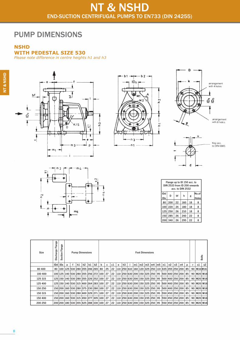
PUMP DIMENSIONSNSHDWITH PEDESTAL SIZE 530Please note difference in centre heights h1 and h3
Flange up to ID 150 acc. toDIN 2533 from ID 200 onwards
acc. to DIN 2532
seloHsDI
80 200 22 160 18 8
100 220 24 180 18 8
125 250 26 210 18 8
150 285 26 240 22 8
200 340 26 295 22 8
NT & NSHDEND-SUCTION CENTRIFUGAL PUMPS TO EN733 (DIN 24255)
Size
Dis
char
ge F
lang
e
Suct
ion
Flan
ge
snoisnemiD tooFsnoisnemiD pmuP
Bol
ts
IDd IDs a f h1 h2 b1 b2 b c c1 e h3 i m1 m2 m3 m4 m5 n1 n2 n3 n4 p r s1 s2
100 400 100 125 140 530 280 355 256 272 100 27 22 110 250 630 200 150 325 250 95 500 400 250 200 85 90 M20 M16
125 315 125 150 140 530 280 355 226 252 100 27 22 110 250 630 200 150 325 250 95 500 400 250 200 85 90 M20 M16
125 400 125 150 140 530 315 400 264 283 100 27 22 110 250 630 200 150 325 250 95 500 400 250 200 85 90 M20 M16
150 250 150 200 160 530 280 375 230 280 100 27 22 110 250 630 200 150 325 250 95 500 400 250 200 85 90 M20 M16
150 315 150 200 160 530 280 400 329 271 100 27 22 110 250 630 200 150 325 250 95 550 450 250 200 85 90 M20 M16
150 400 150 200 160 530 315 450 277 305 100 27 22 110 250 630 200 150 235 250 95 550 450 250 200 85 90 M20 M16
200 250 200 200 180 530 355 425 288 330 100 27 22 110 250 630 200 150 325 250 95 550 450 250 200 85 90 M20 M16
8
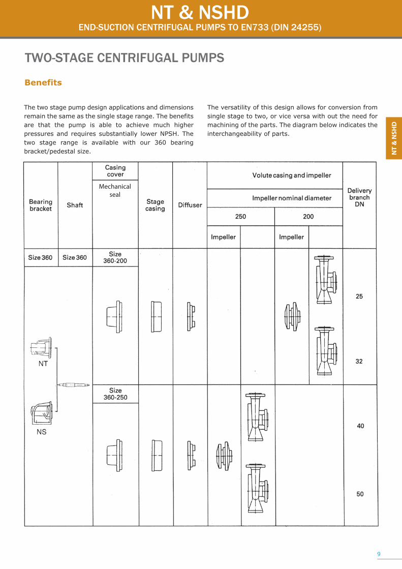
Benefits
TWO-STAGE CENTRIFUGAL PUMPS
The two stage pump design applications and dimensions remain the same as the single stage range. The benefits are that the pump is able to achieve much higher pressures and requires substantially lower NPSH. The two stage range is available with our 360 bearing bracket/pedestal size.
The versatility of this design allows for conversion from single stage to two, or vice versa with out the need for machining of the parts. The diagram below indicates the interchangeability of parts.
NT & NSHDEND-SUCTION CENTRIFUGAL PUMPS TO EN733 (DIN 24255)
9
Mechanical seal

NT & NSHDEND-SUCTION CENTRIFUGAL PUMPS TO EN733 (DIN 24255)
SECTIONAL DRAWINGS & PARTS LIST
HYDRAULIC/LIQUID END
SHAFT SEALING
SINGLE-STAGE PUMP TWO-STAGE PUMP
STUFFING BOX MECHANICAL SEAL
MATCHING RING
10
NT & NSHDEND-SUCTION CENTRIFUGAL PUMPS TO EN733 (DIN 24255)
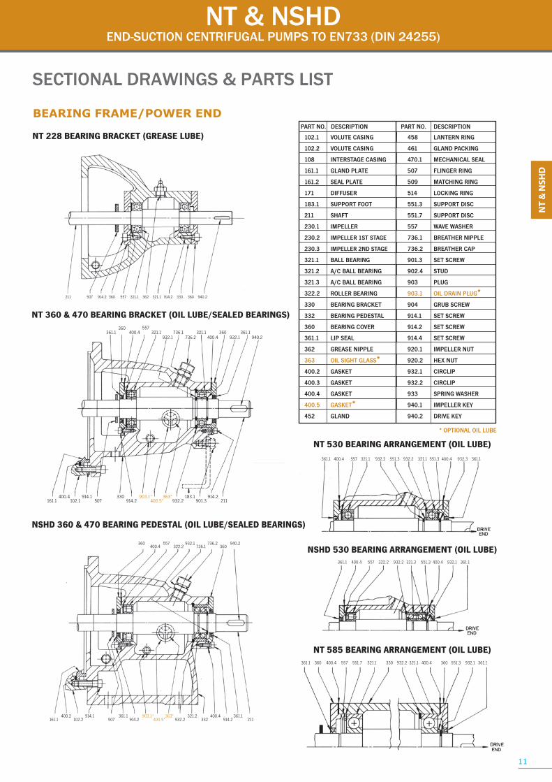
SECTIONAL DRAWINGS & PARTS LIST
BEARING FRAME/POWER END
NT 228 BEARING BRACKET (GREASE LUBE)
NT 360 & 470 BEARING BRACKET (OIL LUBE/SEALED BEARINGS)
NSHD 360 & 470 BEARING PEDESTAL (OIL LUBE/SEALED BEARINGS)
NT 530 BEARING ARRANGEMENT (OIL LUBE)
211 507 914.2 360 557 321.1 362 321.1 914.2 330 360 940.2
361.1360
400.4557
321.1932.1
736.1736.2
321.1400.4
360932.1
361.1940.2
161.1400.4
102.1914.1
507330
914.2903.1*
400.5*363*
932.2183.1
901.3914.2
211
360400.4
557322.2
932.1736.1
736.2360
940.2
161.1400.2
102.2914.1
507361.1
914.2903.1*
400.5*363*
932.2321.2
332400.4
914.2361.1
211
361.1 400.4 557 321.1 932.2 551.3 932.2 321.1 551.3 400.4 932.3 361.1
NSHD 530 BEARING ARRANGEMENT (OIL LUBE)361.1 400.4 557 322.2 932.2 321.3 551.3 400.4 932.1 361.1
NT 585 BEARING ARRANGEMENT (OIL LUBE)361.1 360 400.4 557 551.7 321.1 330 932.2 321.1 400.4 360 551.3 932.1 361.1
102.1 VOLUTE CASING
102.2 VOLUTE CASING
108 INTERSTAGE CASING
161.1 GLAND PLATE
161.2 SEAL PLATE
171 DIFFUSER
183.1 SUPPORT FOOT
211 SHAFT
230.1 IMPELLER
230.2 IMPELLER 1ST STAGE
230.3 IMPELLER 2ND STAGE
321.1 BALL BEARING
321.2 A/C BALL BEARING
321.3 A/C BALL BEARING
322.2 ROLLER BEARING
330 BEARING BRACKET
332 BEARING PEDESTAL
360 BEARING COVER
361.1 LIP SEAL
362 GREASE NIPPLE
363 OIL SIGHT GLASS*400.2 GASKET
400.3 GASKET
400.4 GASKET
400.5 GASKET*452 GLAND
458 LANTERN RING
461 GLAND PACKING
470.1 MECHANICAL SEAL
507 FLINGER RING
509 MATCHING RING
514 LOCKING RING
551.3 SUPPORT DISC
551.7 SUPPORT DISC
557 WAVE WASHER
736.1 BREATHER NIPPLE
736.2 BREATHER CAP
901.3 SET SCREW
902.4 STUD
903 PLUG
903.1 OIL DRAIN PLUG*904 GRUB SCREW
914.1 SET SCREW
914.2 SET SCREW
914.4 SET SCREW
920.1 IMPELLER NUT
920.2 HEX NUT
932.1 CIRCLIP
932.2 CIRCLIP
933 SPRING WASHER
940.1 IMPELLER KEY
940.2 DRIVE KEY
* OPTIONAL OIL LUBE
11

TOMBSTONE CURVES
NT & NSHDEND-SUCTION CENTRIFUGAL PUMPS TO EN733 (DIN 24255)
12
2 3 4 6 8 10 20 30 40 60 80 100
FLOW RATE [m3/h]
200 300 400 600 800 1000 16002
3
4
6
8
10
[m]
20
30
40
60
80
25-160
25-200
32-160
32-200
40-200
2/25-2002/32-200
40-160
65-16080-160
50-160
100-200
80-200
65-200
50-200
100-25080-250
65-250
40-25050-250
2/40-250
2/50-250
125-250150-250
200-25065-315
65-400
80-315
100-315
125-315
150-315
200-315
250-315
80-400100-400
125-400
200-400250-400
125-400/1 150-400/1
HEA
D
10
20
30
40
100
160
70
2 3 4 6 8 10
FLOW RATE [m3/h]
20 60 100 200 300 400 700
25-160
25-200
32-160
32-200
40-200
2/25-200 2/32-200
40-160
65-16080-160
50-160
125-250
100-200
80-200
65-200
50-200
100-250
80-250
65-25040-250
50-250
2/40-250
2/50-250
[m]
HEA
D
1450 rpm
2900 rpm
Pg. no.
25-160 2 4225-200 3 432/25-200 4 4432-160 5 4532-200 6 462/32-200 7 4740-160 8 4840-200 9 4940-250 10 502/40-250 11 5150-160 12 5250-200 13 5350-250 14 542/50-250 15 5565-160 16 5665-200 17 5765-250 18 5865-315 19 65-400 2080-160 21 5980-200 22 6080-250 23 6180-315 24 80-400 25100-200 26 62100-250 27 63100-315 28100-400 29125-250 30 64125-315 31125-400 32125-400/1 33150-250 34150-315 35150-400/1 36200-250 37200-315 38200-400 39250-315 40250-400 41
Size*
* FOR INDIVIDUAL PUMP PERFORMANCE CURVES, REFER TO OUR EN733 (DIN 24255) CURVES BOOK.

NBMONOBLOCK END-SUCTION CENTRIFUGAL PUMPS TO EN733 (DIN 24255)
APPLICATION• Air-Conditioning• Water Supply• Irrigation• Water Treatment• Circulating and Heating Systems• Swimming Pools• Chemical and Petro-Chemical Industries
NB 2 530 3 140 160˚C
RA Pump Range
Minimum Flow (m3/h)
Maximum Flow (m3/h)
Minimum Head (m)
Maximum Head (m)
Maximum Temperature
DESIGN & CONSTRUCTION • Suitable for clean liquids which are not chemically aggressive. • Single and two stage options available. • Balance holes are drilled in the impeller to effect hydraulic balance eliminating undue forces with in the pump. • Gland Packing or Mechanical Seal options available. • High interchange ability of parts allowing for minimal spares holdings. • Space saving design compared to long coupled pump sets.
• More cost economical option compared to long coupled pump sets.
• Designed for horizontal installation with vertical optional.
• Drive Coupling and Stub Shaft design which utilizes standard IEC flange mounted electric motors. • The Stub Shaft is attached directly to the motor shaft and runs on the grease lubricated motor bearings.
Flanges • SANS 1123 PN10(BS 4504 PN10) or ANSI B16.5 (optional).• Horizontal suction and the discharge may used in various positions (per the Branch Position diagram see page no. 6)
MATERIALS OF CONSTRUCTIONPump Shaft: Grade 431 or 316 Stainless steelVolute Casing: High Grade Cast Iron, BronzeImpeller: Cast Iron, Stainless Steel or BronzeShaft Sealing: Stuffing box or Mechanical seal (Cooled or Uncooled) to suit applicationMotor Bearings: Grease lubricated ball bearings
MotorStandard I.E.C flange mounted or foot and flangemounted, three phase 380 or 525 volt, totally enclosed fan cooled motors are used with either cast iron oraluminum bodies. Non standard motors can be supplied upon request.
MODEL DESCRIPTIONNB 50-250 CCP 120 Motor Frame Size Seal Arrangement Impeller Volute Material Nominal Impeller Diameter in mm Discharge Size in mmPump Type 13
NBMONOBLOCK END-SUCTION CENTRIFUGAL PUMPS TO EN733 (DIN 24255)
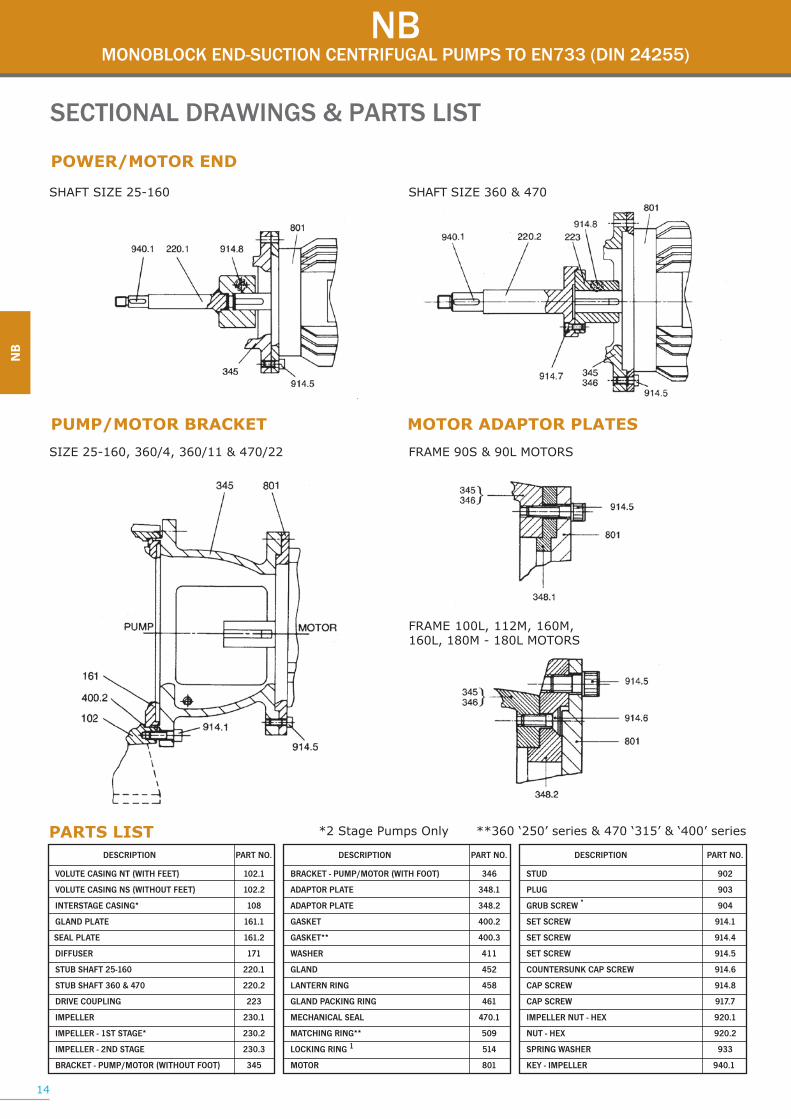
SECTIONAL DRAWINGS & PARTS LIST
POWER/MOTOR END
PUMP/MOTOR BRACKET MOTOR ADAPTOR PLATES
SHAFT SIZE 25-160
SIZE 25-160, 360/4, 360/11 & 470/22 FRAME 90S & 90L MOTORS
SHAFT SIZE 360 & 470
FRAME 100L, 112M, 160M,160L, 180M - 180L MOTORS
PARTS LIST *2 Stage Pumps Only **360 ‘250’ series & 470 ‘315’ & ‘400’ series
DESCRIPTION PART NO.
VOLUTE CASING NT (WITH FEET) 102.1
VOLUTE CASING NS (WITHOUT FEET) 102.2
801*GNISAC EGATSRETNI
1.161ETALP DNALG
2.161ETALP LAES
171RESUFFID
1.022061-52 TFAHS BUTS
2.022074 & 063 TFAHS BUTS
322GNILPUOC EVIRD
1.032RELLEPMI
2.032*EGATS TS1 - RELLEPMI
IMPELLER - 2ND STAGE 230.3
BRACKET - PUMP/MOTOR (WITHOUT FOOT) 345
DESCRIPTION PART NO.
BRACKET - PUMP/MOTOR (WITH FOOT) 346
1.843ETALP ROTPADA
2.843ETALP ROTPADA
2.004TEKSAG
3.004**TEKSAG
114REHSAW
254DNALG
854GNIR NRETNAL
164GNIR GNIKCAP DNALG
1.074LAES LACINAHCEM
905**GNIR GNIHCTAM
LOCKING RING 1 514
108ROTOM
DESCRIPTION PART NO.
209DUTS
309GULP
GRUB SCREW * 904
1.419WERCS TES
4.419WERCS TES
5.419WERCS TES
COUNTERSUNK CAP SCREW 914.6
8.419WERCS PAC
7.719WERCS PAC
1.029XEH - TUN RELLEPMI
2.029XEH - TUN
339REHSAW GNIRPS
1.049RELLEPMI - YEK
14
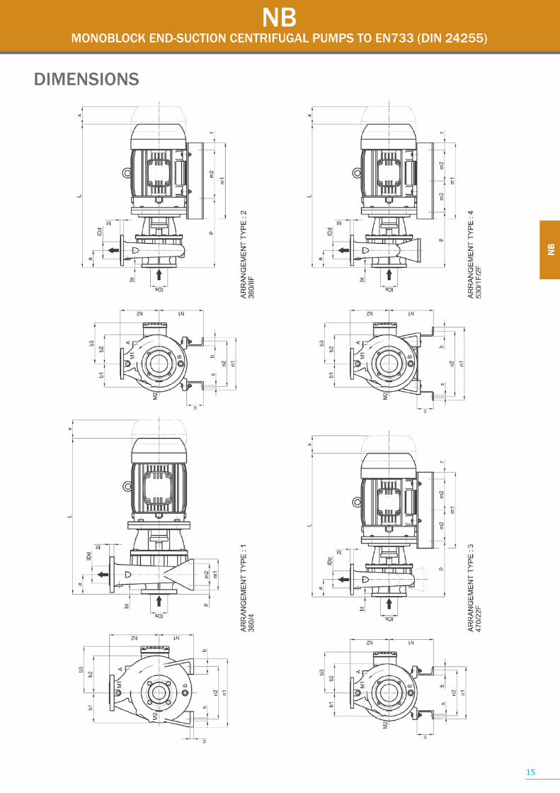
NBMONOBLOCK END-SUCTION CENTRIFUGAL PUMPS TO EN733 (DIN 24255)
DIMENSIONS
15
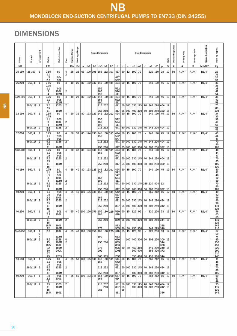
NBMONOBLOCK END-SUCTION CENTRIFUGAL PUMPS TO EN733 (DIN 24255)
DIMENSIONS
Pum
p
Arra
ngem
ent
Bol
ts
Mot
or fr
ame
Size
Suct
ion
Flan
ge
Dis
char
ge F
lang
e
Dis
man
tling
Spa
ce
Pri
ning
Hol
e
Dra
inag
e H
ole
Gau
ge C
onne
ctio
n
Mas
s kg
App
rox.
Bra
cket
Mot
or
Pol
e
16

NBMONOBLOCK END-SUCTION CENTRIFUGAL PUMPS TO EN733 (DIN 24255)
DIMENSIONS
17
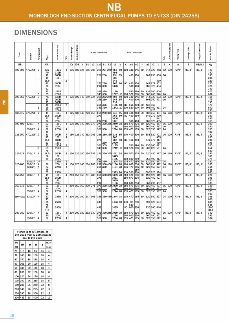
NBMONOBLOCK END-SUCTION CENTRIFUGAL PUMPS TO EN733 (DIN 24255)
DIMENSIONS
18
Flange up to ID 150 acc. toDIN 2533 from ID 200 onwards
acc. to DIN 2532
No. of
IDd Holes
25 115 16 85 14 4
32 140 18 100 18 4
40 150 18 110 18 4
50 165 20 125 18 4
65 185 20 145 18 4
80 200 22 160 18 8
100 220 24 180 18 8
125 250 26 210 18 8
150 285 26 240 22 8
200 340 26 295 22 12
250 395 28 350 22 12
300 445 28 400 22 12

Pg. no.
25-160 2 4225-200 3 432/25-200 4 4432-160 5 4532-200 6 462/32-200 7 4740-160 8 4840-200 9 4940-250 10 502/40-250 11 5150-160 12 5250-200 13 5350-250 14 542/50-250 15 5565-160 16 5665-200 17 5765-250 18 5865-315 19 65-400 2080-160 21 5980-200 22 6080-250 23 6180-315 24 80-400 25100-200 26 62100-250 27 63100-315 28100-400 29125-250 30 64125-315 31125-400 32125-400/1 33150-250 34150-315 35150-400/1 36200-250 37
Size*
19
NBMONOBLOCK END-SUCTION CENTRIFUGAL PUMPS TO EN733 (DIN 24255)
TOMBSTONE CURVES
* FOR INDIVIDUAL PUMP PERFORMANCE CURVES, REFER TO OUR EN733 (DIN 24255) CURVES BOOK.
2 3 4 6 8 10 20 30 40 60 80 100 200 300 400 600 800
25-160
25-200
32-160
32-200
40-200
2/25-2002/32-200
40-160 65-16080-160
50-160
100-200
80-200
65-200
50-200
100-250
80-25065-250
40-250
50-250
2/40-250
2/50-250
125-250150-250
200-250
65-315
65-400
80-315
100-315125-315
150-315
80-400100-400
125-400
2 3 4 6 8 10 20 60 100 200 300 400 700
25-160
25-200
32-160
32-200
40-200
2/25-200 2/32-200
40-160 65-160
80-160
50-160
125-250
100-200
80-200
65-200
50-200
80-250
65-250
40-25050-250
2/40-250 2/50-250
FLOW RATE [m3/h]
FLOW RATE [m3/h]
2900 rpm
1450 rpm
2
3
4
6
8
10
[m]
H
20
30
40
60
80
10
20
30
40
100
160
70
[m]
H
HE
AD
HE
AD

DVVERTICAL SPINDLE CENTRIFUGAL PUMP TO EN733 (DIN 24255)
RA Pump Range
Minimum Flow (m3/h)
Maximum Flow (m3/h)
Minimum Head (m)
Maximum Head (m)
Maximum Temperature
DV 4 400 3 90 120˚C
APPLICATION• Industrial• Agricultural• Refinery• Mining Industries• Lubrication System
DESIGN & CONSTRUCTION • Vertical spindle design with electric motor on top and liquid end below.
• Suitable for pumping a variety of liquids and can handle solids in suspension and also run dry for short periods. • Balance holes are drilled in the impeller to effect hydraulic balance eliminating undue forces with in the pump. • Double Mechanical Seal that run in an oil bath.
• High interchangeability of parts, allowing for minimal spares holdings.
• Suitable for wet and dry pit installations.
• Replaceable shaft sleeves are fitted as standard.
• Heavy duty shaft supported by bearings in the column.
• Parts are easily removed for inspection, service and maintenance.
• Column lengths available from 400mm to 2400mm.
Flanges• SANS 1123 PN10(BS 4504 PN10) or ANSI B16.5.
MATERIALS OF CONSTRUCTIONVolute Casing: High Grade Cast Iron, Bronze or Stainless SteelImpeller: Cast Iron or Bronze Column: Mild Steel/Stainless SteelMounting Flange: Mild Steel/Stainless SteelMotor: Standard IECMotor Stool: Mild Steel/Stainless SteelBall Bearings: Grease LubricationLower shaft sleeve: Stainless SteelUpper shaft sleeve: Mild SteelDischarge pipe: Mild SteelMechanical seal: Double arrangementShaft: EN8/316 MODEL DESCRIPTIOND V S/L 50 250 1400
Column Length mm Nominal Impeller Diameter in mm Discharge Size in mm Bearing Bracket S = Small L = Large VerticalDIN
20

DVVERTICAL SPINDLE CENTRIFUGAL PUMP TO EN733 (DIN 24255)
21
DIMENSIONS
PumpModel
Column Length Discharge FlangeDIN 2532 PN10*
Mounting Plate
A B A B A B A B A B C D PCD N F G H J K
32-160 32 100
32-200 506 1006 1506 2506
40-16016
40-200 40 110
40-250
50-160 426 926 1426 1926 2426 4 356 279 483 381 247
50-200 526 1026 1526 2026 2526 50 125
50-250
65-16016
65-200 65 145
80-160 551 1051 1551 2051 2551 80 160
65-250 538 1038 1538 2038 2538
65-315 65 145
65-400
80-20043652360236513601365
80-250 438 938 1438 1938 2438 80 16 160 527 356 660 559 324
80-315
100-200100 180
100-250 8
100-315578 1078 1578 2078 2578
125-250 125 20 210
All dimensions in mm
DVS
DVL

SECTIONAL DRAWING
DVVERTICAL SPINDLE CENTRIFUGAL PUMP TO EN733 (DIN 24255)
22
Electric Motor
Flanged Discharge Pipe
Coupling
Upper Motor BracketUpper “O” RingUpper BearingUpper Bearing Housing
Mounting Plate
Upper Lip-sealBearing Cover
Pump Shaft
Flanged Column
Bearing Cover
Intermediate Lip-seal
Lower Lip-seal
Intermediate “O” Ring
Intermediate “O” Ring
Lower “O” Ring
Lower Pump Motor BracketMechanical Seal
Lower BearingLower Bearing Housing
Impeller
Casing
Strainer
Seal Failure Indicator Pipe
Bearing Cover
Intermediate BRGIntermediate BRG Housing
Impeller KeyImpeller Masher
Impeller Nut
Flanged Column

DVVERTICAL SPINDLE CENTRIFUGAL PUMP TO EN733 (DIN 24255)
23
PARTS LIST
DescriptionCouplingUpper Motor BracketFlanged Discharge PipeImpellerImpeller KeyImpeller MasherImpeller NutElectric MotorUpper, Intermediate & Lower “O” RingUpper, Intermediate & Lower BearingUpper, Intermediate & Lower Bearing HousingMounting PlateUpper, Intermediate & Lower Lip-SealBearing CoverPump ShaftFlanged ColumnSeal Failure Indicator PipeMechanical SealCasingStrainer
Part223346.2211230940.1933920.1801496321.1134.B203361.1360211200.1202.1470.1102.3202.2

Pg. no.
32-160 5 4532-200 6 4640-160 8 4840-200 9 4940-250 10 5050-160 12 5250-200 13 5350-250 14 5465-160 16 5665-200 17 5765-250 18 5865-315 19 65-400 2080-160 21 5980-200 22 6080-250 23 6180-315 24 100-200 26 62100-250 27 63100-315 28125-250 30 64
Size*
DVVERTICAL SPINDLE CENTRIFUGAL PUMP TO EN733 (DIN 24255)
TOMBSTONE CUVES
* FOR INDIVIDUAL PUMP PERFORMANCE CURVES, REFER TO OUR EN733 (DIN 24255) CURVES BOOK.24
2 3 4 6 8 10 20 30 40 60 80 100 200 300 400 600 8002
3
4
6
8
10
20
30
40
60
80
32-160
32-200
40-200
40-160 65-16080-160
50-160
100-200
80-200
65-200
50-200
100-250
80-25065-250
40-250
50-250
125-25065-315
65-400
80-315
100-315
10
20
30
40
100
160
70
2 3 4 6 8 10 20 60 100 200 300 400 700
32-160
32-200
40-200
40-160 65-160
80-160
50-160
125-250
100-200
80-200
65-200
50-200
80-250
65-250
40-25050-250
[m]
HE
AD
FLOW RATE [m3/h]
1450 rpm
[m]
HE
AD
FLOW RATE [m3/h]
2900 rpm

Centrifugal and Axial Flow Pump Affinity Laws:
Speed changes & impeller diameter remains the same:
Q1/Q2 = N1/N2
H1/H2 = (N1/N2)²
P1/P2 = (N1/N2)³
Impeller diameter changes and speed remains the same:
Q1/Q2 = D1/D2
H1/H2 = (D1/D2)²
P1/P2 = (D1/D2)³
BASIC FORMULAS Q = Flow(m³/h)H= Head(m) Density = SGEff = Pump Eff%
Capacity
l/sec x 3.6 = m³/h m³/h ÷ 3.6 = l/sec
US gpm ÷ 0.246 = l/min l/min x 0.246 = US gpm
Imp gpm x 0.2271 = m³/h m³/h x 4.403 = Imp gpm
10000 kg/hr =10m³h
Density(SG)
Head/Pressure
Ft ÷ 3.28 = m m x 3.28048 = Ft
m x 9.805 = kpa kpa x 0.102 = m
m x 1.45 = psi
Bar x 10.19 = m
Bar x 100 = kpa
m x 0.098 = Bar
psi x 6.895 = kpa
Efficiency
EFF(%) = Q x H x SG
367 x kw(abs)
Q x H x SG367 x Eff(%)
Power
hp x 0.746 = kw kw x 1.340483 = hp
kw abs =
Hz x 120No of Poles
RPM =
RPM x No Of Poles120
Hz =
Q x 353.63(Pipe Dia)²
Velocity m/sec =
Amps x Volts x Power Factor x 1.7321000
kw =
Temperature
Deg.C = (deg.F-32) x 0.556
Deg.F = (1.8 x deg.C) + 32
imp.dia.(mm) x π x N(Rpm)
60 000
Peripheral Speed
Peripheral Speed(Impeller) =
QvisCQ
Qw =
C% x %wQw =
Qvis x Hvis x Pvis367 x Eff(%) vis
Pvis =
HvisCH
Hw =
Viscosity
vis Viscous Liquid
w Water
Given: Qvis in m³/h
Hvis in m
kinematic viscosity v in mm²/s
pvis in kg/dm³

08600 RAPID
10 Girder Street • Isando • 1601T: +27 11 573 7400 • F: +27 11 974 8757
www.rapidallweiler.co.za