nth25/25c programmable terminal -...
TRANSCRIPT
Cat. No. V054-E1-1
Programmable TerminalNTH25/25C
iii
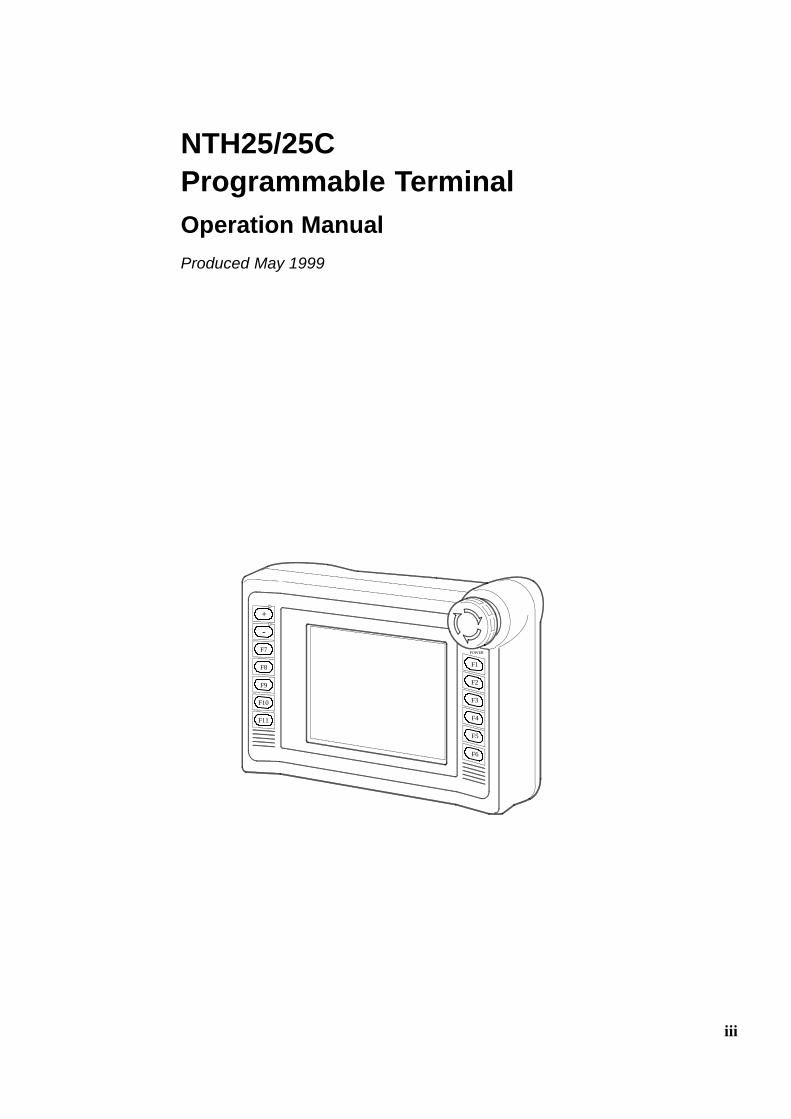
NTH25/25CProgrammable TerminalOperation ManualProduced May 1999
+
--
F7
F8
F9
F10
F11
POWER
F1
F2
F3
F4
F5
F6
v
OMRON Product ReferencesAll OMRON products are capitalized in thismanual. Theword “Unit” is also capitalizedwhen it refers to anOMRON product, regardless of whether or not it appears in the proper name of the product.
The abbreviation “Ch,” which appears in some displays and on some OMRON products, often means“word” and is abbreviated “Wd” in documentation in this sense.
The abbreviation “PC” means Programmable Controller and is not used as an abbreviation for anythingelse.
The abbreviation “Host” means a controller such as an FA computer which controls a PT (programmableterminal).
Visual AidsThe following headings appear in the left column of the manual to help you locate different types of infor-mation.
Reference Indicates information of particular interest for efficient and convenient operationof the product.
1, 2, 3... 1. Indicates lists of one sort or another, such as procedures, checklists, etc.
OMRON, 1999All rights reserved. No part of this publication may be reproduced, stored in a retrieval system, or transmitted, in anyform, or by any means, mechanical, electronic, photocopying, recording, or otherwise, without the prior written permis-sion of OMRON.
No patent liability is assumed with respect to the use of the information contained herein. Moreover, because OMRONis constantly striving to improve its high-quality products, the information contained in this manual is subject to changewithout notice. Every precaution has been taken in the preparation of this manual. Nevertheless, OMRON assumes noresponsibility for errors or omissions. Neither is any liability assumed for damages resulting from the use of the infor-mation contained in this publication.
vii
TABLE OF CONTENTS
PRECAUTIONS xiii. . . . . . . . . . . . . . . . . . . . . . . . . . . . . . . . .1 Intended Audience xiv. . . . . . . . . . . . . . . . . . . . . . . . . . . . . . . . . . . . . . . . . . . . . . . . . . . . . .2 General Precautions xiv. . . . . . . . . . . . . . . . . . . . . . . . . . . . . . . . . . . . . . . . . . . . . . . . . . . . .3 Safety Precautions xiv. . . . . . . . . . . . . . . . . . . . . . . . . . . . . . . . . . . . . . . . . . . . . . . . . . . . . .
SECTION 1General 1. . . . . . . . . . . . . . . . . . . . . . . . . . . . . . . . . . . . . . . . .1-1 Role and Operation of the NTH25/NTH25C 2. . . . . . . . . . . . . . . . . . . . . . . . . . . . . . . . .1-2 Functions of the NTH25/NTH25C 4. . . . . . . . . . . . . . . . . . . . . . . . . . . . . . . . . . . . . . . . .1-3 Communications with the Host 15. . . . . . . . . . . . . . . . . . . . . . . . . . . . . . . . . . . . . . . . . . . .1-4 Communications by Using Memory Link 22. . . . . . . . . . . . . . . . . . . . . . . . . . . . . . . . . . . .1-5 System Configuration 24. . . . . . . . . . . . . . . . . . . . . . . . . . . . . . . . . . . . . . . . . . . . . . . . . . .1-6 Before Operating the NTH25/NTH25C 26. . . . . . . . . . . . . . . . . . . . . . . . . . . . . . . . . . . . .
SECTION 2Connection 29. . . . . . . . . . . . . . . . . . . . . . . . . . . . . . . . . . . . . .2-1 Method for Connection to the Host 30. . . . . . . . . . . . . . . . . . . . . . . . . . . . . . . . . . . . . . . . .2-2 Names and Functions of Parts 32. . . . . . . . . . . . . . . . . . . . . . . . . . . . . . . . . . . . . . . . . . . . .2-3 Wiring Cable Functions and Connections 34. . . . . . . . . . . . . . . . . . . . . . . . . . . . . . . . . . . .2-4 Connecting to the NTH Screen Data Converter 38. . . . . . . . . . . . . . . . . . . . . . . . . . . . . . .2-5 Connecting to the Host 40. . . . . . . . . . . . . . . . . . . . . . . . . . . . . . . . . . . . . . . . . . . . . . . . . .
SECTION 3CHECK Menu Operation 59. . . . . . . . . . . . . . . . . . . . . . . . . .3-1 CHECK Menu Operation Flow 60. . . . . . . . . . . . . . . . . . . . . . . . . . . . . . . . . . . . . . . . . . . .3-2 Starting the NTH25/NTH25C 61. . . . . . . . . . . . . . . . . . . . . . . . . . . . . . . . . . . . . . . . . . . . .3-3 Operation Modes and the CHECK menu 62. . . . . . . . . . . . . . . . . . . . . . . . . . . . . . . . . . . .3-4 Transmitting the Screen Data 65. . . . . . . . . . . . . . . . . . . . . . . . . . . . . . . . . . . . . . . . . . . . .3-5 Starting Operation 67. . . . . . . . . . . . . . . . . . . . . . . . . . . . . . . . . . . . . . . . . . . . . . . . . . . . . .3-6 Switching the Display Language 69. . . . . . . . . . . . . . . . . . . . . . . . . . . . . . . . . . . . . . . . . . .3-7 Adjusting LCD Contrast 70. . . . . . . . . . . . . . . . . . . . . . . . . . . . . . . . . . . . . . . . . . . . . . . . .3-8 Setting the Clock Data 71. . . . . . . . . . . . . . . . . . . . . . . . . . . . . . . . . . . . . . . . . . . . . . . . . . .3-9 Checking Screen Data 73. . . . . . . . . . . . . . . . . . . . . . . . . . . . . . . . . . . . . . . . . . . . . . . . . . .3-10 Programming Console Function 74. . . . . . . . . . . . . . . . . . . . . . . . . . . . . . . . . . . . . . . . . . .
SECTION 4NTH25/NTH25C Functions 79. . . . . . . . . . . . . . . . . . . . . . . .4-1 PT Configuration Settings 80. . . . . . . . . . . . . . . . . . . . . . . . . . . . . . . . . . . . . . . . . . . . . . . .4-2 NTH25/NTH25C Screen 83. . . . . . . . . . . . . . . . . . . . . . . . . . . . . . . . . . . . . . . . . . . . . . . . .4-3 Areas for Control/Notification 89. . . . . . . . . . . . . . . . . . . . . . . . . . . . . . . . . . . . . . . . . . . . .4-4 Memory Tables 98. . . . . . . . . . . . . . . . . . . . . . . . . . . . . . . . . . . . . . . . . . . . . . . . . . . . . . . .4-5 Fixed Displays 109. . . . . . . . . . . . . . . . . . . . . . . . . . . . . . . . . . . . . . . . . . . . . . . . . . . . . . . . .4-6 Image and Library Data 130. . . . . . . . . . . . . . . . . . . . . . . . . . . . . . . . . . . . . . . . . . . . . . . . . .4-7 Lamps 137. . . . . . . . . . . . . . . . . . . . . . . . . . . . . . . . . . . . . . . . . . . . . . . . . . . . . . . . . . . . . . . .4-8 Touch Switches 145. . . . . . . . . . . . . . . . . . . . . . . . . . . . . . . . . . . . . . . . . . . . . . . . . . . . . . . .4-9 Numeral Display 159. . . . . . . . . . . . . . . . . . . . . . . . . . . . . . . . . . . . . . . . . . . . . . . . . . . . . . .
viii
4-10 Character String Display 166. . . . . . . . . . . . . . . . . . . . . . . . . . . . . . . . . . . . . . . . . . . . . . . . .4-11 Graphs 172. . . . . . . . . . . . . . . . . . . . . . . . . . . . . . . . . . . . . . . . . . . . . . . . . . . . . . . . . . . . . . .4-12 Alarm List, Alarm History 189. . . . . . . . . . . . . . . . . . . . . . . . . . . . . . . . . . . . . . . . . . . . . . . .4-13 Inputting Numerals 196. . . . . . . . . . . . . . . . . . . . . . . . . . . . . . . . . . . . . . . . . . . . . . . . . . . . .4-14 Special Functions 211. . . . . . . . . . . . . . . . . . . . . . . . . . . . . . . . . . . . . . . . . . . . . . . . . . . . . . .
SECTION 5Using Memory Link (NTH Protocol) 219. . . . . . . . . . . . . . . . .5-1 Operation of Memory Link 220. . . . . . . . . . . . . . . . . . . . . . . . . . . . . . . . . . . . . . . . . . . . . . .5-2 Outline of Communications 224. . . . . . . . . . . . . . . . . . . . . . . . . . . . . . . . . . . . . . . . . . . . . . .5-3 Data Structure According to Display Element and Function 230. . . . . . . . . . . . . . . . . . . . .
SECTION 6NTH Screen Data Converter 249. . . . . . . . . . . . . . . . . . . . . . .6-1 Outline of NTH Screen Data Converter 250. . . . . . . . . . . . . . . . . . . . . . . . . . . . . . . . . . . . .6-2 Setting Up NTH Screen Data Converter 252. . . . . . . . . . . . . . . . . . . . . . . . . . . . . . . . . . . . .6-3 Operating NTH Screen Data Converter 259. . . . . . . . . . . . . . . . . . . . . . . . . . . . . . . . . . . . .
SECTION 7Troubleshooting and Maintenance 275. . . . . . . . . . . . . . . . . . .7-1 Troubleshooting 276. . . . . . . . . . . . . . . . . . . . . . . . . . . . . . . . . . . . . . . . . . . . . . . . . . . . . . . .7-2 Maintenance of the NTH25/NTH25C 281. . . . . . . . . . . . . . . . . . . . . . . . . . . . . . . . . . . . . . .7-3 Inspection and Cleaning 282. . . . . . . . . . . . . . . . . . . . . . . . . . . . . . . . . . . . . . . . . . . . . . . . .
APPENDICES 285. . . . . . . . . . . . . . . . . . . . . . . . . . . . . . . . . . .A Specifications 286. . . . . . . . . . . . . . . . . . . . . . . . . . . . . . . . . . . . . . . . . . . . . . . . . . . . . . . . . .B Dimensions 292. . . . . . . . . . . . . . . . . . . . . . . . . . . . . . . . . . . . . . . . . . . . . . . . . . . . . . . . . . .C Using an RS--232C/RS--422A Converter Unit 293. . . . . . . . . . . . . . . . . . . . . . . . . . . . . . . .D Transporting and Storing the NTH25/NTH25C 299. . . . . . . . . . . . . . . . . . . . . . . . . . . . . . .E Making the Cable 300. . . . . . . . . . . . . . . . . . . . . . . . . . . . . . . . . . . . . . . . . . . . . . . . . . . . . . .F Differences with NT31/NT31C Screen Data 303. . . . . . . . . . . . . . . . . . . . . . . . . . . . . . . . . .G Model List 316. . . . . . . . . . . . . . . . . . . . . . . . . . . . . . . . . . . . . . . . . . . . . . . . . . . . . . . . . . . .H PC Memory Map 321. . . . . . . . . . . . . . . . . . . . . . . . . . . . . . . . . . . . . . . . . . . . . . . . . . . . . . .I Keycode Tables 323. . . . . . . . . . . . . . . . . . . . . . . . . . . . . . . . . . . . . . . . . . . . . . . . . . . . . . . .
INDEX 325. . . . . . . . . . . . . . . . . . . . . . . . . . . . . . . . . . . . . . . . .
ix
About this Manual:
This manual describes the basic functions and operation procedures of the NTH-series programmableterminal NTH25/NTH25C, its operations when connected to a PC or a Host, and includes the sectionsdescribed below.
Please read this manual carefully and be sure you understand the information provided before attemptingto install and operate the NTH-series programmable terminal NTH25/NTH25C.
Section 1 describes the functions and configuration of the NTH25/NTH25C.
Section 2 gives basic information on the method for connecting to the host and communication methods,and describes the names and functions of the parts of the NTH25/NTH25C.
Section 3 describes how to use the system menu, which allows various settings and checks to be per-formed using the touch panel of the NTH25/NTH25C.
Section 4 describes the functions of the NTH25/NTH25C, focusing on the functions of the display ele-ments that can be registered for the screens.
Section 5 describes how to use the NTH25/NTH25C, when using memory link
Section 6 describes how to use the NTH Screen Data Converter.
Section 7 describes the corrective action to take when the system does not function normally, and theprocedures for daily maintenance of the NTH25/NTH25C.
APPENDIX describes the specifications and method for making connector cables, and includes a list ofrelated parts and a PC area map.

x
Related Manuals and Their Contents:
The related manuals are listed below.
The j symbol at the end of the manual number is the revision history number.
[Operating the programmable terminal and communicating with the host]
S NTH25/25C Programmable Terminal Operation Manual (V054-E1-j)This manual. . . . . . . . . . . . . . . . . . . . . . . . . . . . . . . . . . . . . . . . . . . . . . . . . . . . . . .
This operation manual is the manual for the NTH25/25C itself.
This operationmanual describes the functions and handling of both the program-mable terminal body and the host interface function.
[Creating and transferring screen data]
S NT-series Support Tool Operation Manual (V053-E1-j)
The screens displayed on the NTH25/25C are created with the support tool andtransferred to theNTH25/25C. Thismanual describes how to create and transferscreen data.
Note that in this manual, the NT-series Support Tool for Windows 95/98 is re-ferred to as the “Support Tool”.

xi
PRECAUTIONS
This section provides general precautions for using the Programmable Terminal.
The information contained in this section is important for the safe and reliable application of the Programmable Ter-minal. You must read this section and understand the information contained before attempting to set up or operate aProgrammable Terminal.
1 Intended Audience xii. . . . . . . . . . . . . . . . . . . . . . . . . . . . . . . . . . . . . . . . . . . . . . . . . . . . . .2 General Precautions xii. . . . . . . . . . . . . . . . . . . . . . . . . . . . . . . . . . . . . . . . . . . . . . . . . . . . .3 Safety Precautions xii. . . . . . . . . . . . . . . . . . . . . . . . . . . . . . . . . . . . . . . . . . . . . . . . . . . . . .
xii
Precautions
1 Intended AudienceThis manual is intended for the following personnel, who must also have knowl-edge of electrical systems (an electrical engineer or the equivalent).
! Personnel in charge of introducing FA systems into production facilities.
! Personnel in charge of designing FA systems.
! Personnel in charge of installing and connecting FA systems.
! Personnel in charge of managing FA systems and facilities.
2 General PrecautionsThe user must operate the product according to the performance specificationsdescribed in the operation manuals.Before using the product under conditions which are not described in the manualor applying the product to nuclear control systems, railroad systems, aviationsystems, vehicles, combustion systems, medical equipment, amusement ma-chines, safety equipment, and other systems, machines and equipment thatmayhave a serious influence on lives and property if used improperly, consult yourOMRON representative.Make sure that the ratings and performance characteristics of the product aresufficient for the systems, machines, and equipment, and be sure to provide thesystems, machines, and equipment with double safety mechanisms.This manual provides information for using the Programmable Terminal. Be sureto read this manual before attempting to use the NTH25/NTH25C and keep thismanual close at hand for reference during operation.
WARNING It is extremely important that Programmable Terminals and related devices beused for the specified purpose and under the specified conditions, especially inapplications that can directly or indirectly affect human life. Youmust consult withyour OMRON representative before applying Programmable Terminals to theabove-mentioned applications.
WARNING Donot use input functions such as PT touch switches for applications where dan-ger to human life or serious damage is possible, or for emergency switch applica-tions.
3 Safety PrecautionsRead these safety precautions carefully andmake sure you understand thembe-fore using the Programmable Terminal so that you can use it safely and correctly.
Safety Conventions andtheir Meanings This operation manual uses the following conventions and symbols to indicate--
cautions, warnings, and dangers in order to ensure safe use of theNTH25/NTH25C.The cautions, warnings, and dangers shown here contain important informationrelated to safety. These instructions in the cautions, warnings, and dangers mustbe observed.
The conventions used and their meanings are presented below.WARNING Indicates information that, if not heeded, could possibly result in loss of life or seri-
ous injury.
Caution Indicates information that, if not heeded, could result in relatively serious orminorinjury, damage to the product, or faulty operation.
xiii
Precautions
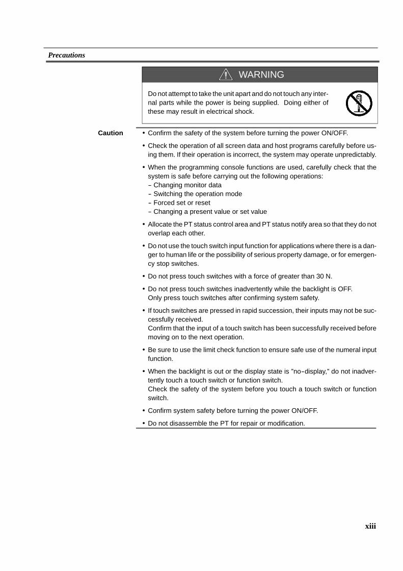
Donot attempt to take the unit apart and do not touch any inter-nal parts while the power is being supplied. Doing either ofthese may result in electrical shock.
Caution ! Confirm the safety of the system before turning the power ON/OFF.
! Check the operation of all screen data and host programs carefully before us-ing them. If their operation is incorrect, the system may operate unpredictably.
! When the programming console functions are used, carefully check that thesystem is safe before carrying out the following operations:-- Changing monitor data-- Switching the operation mode-- Forced set or reset-- Changing a present value or set value
! Allocate the PT status control area and PT status notify area so that they do notoverlap each other.
! Do not use the touch switch input function for applications where there is a dan-ger to human life or the possibility of serious property damage, or for emergen-cy stop switches.
! Do not press touch switches with a force of greater than 30 N.
! Do not press touch switches inadvertently while the backlight is OFF.Only press touch switches after confirming system safety.
! If touch switches are pressed in rapid succession, their inputs may not be suc-cessfully received.Confirm that the input of a touch switch has been successfully received beforemoving on to the next operation.
! Be sure to use the limit check function to ensure safe use of the numeral inputfunction.
! When the backlight is out or the display state is ”no--display,” do not inadver-tently touch a touch switch or function switch.Check the safety of the system before you touch a touch switch or functionswitch.
! Confirm system safety before turning the power ON/OFF.
! Do not disassemble the PT for repair or modification.
WARNING
1
SECTION 1General
This section provides basic information about the functions and features of the NTH25/NTH25C, types of connection andcommunications methods. This information will enable you to understand the applications of the NTH25/NTH25C.
1-1 Role and Operation of the NTH25/NTH25C 2. . . . . . . . . . . . . . . . . . . . . . . . . . . . . . . . . . . . . . .1-1-1 Operation of an NTH25/NTH25C at an FA Production Site 2. . . . . . . . . . . . . . . . . . . . . .1-1-2 Operations of the NTH25/NTH25C 3. . . . . . . . . . . . . . . . . . . . . . . . . . . . . . . . . . . . . . . . .
1-2 Functions of the NTH25/NTH25C 4. . . . . . . . . . . . . . . . . . . . . . . . . . . . . . . . . . . . . . . . . . . . . . .1-2-1 Features 4. . . . . . . . . . . . . . . . . . . . . . . . . . . . . . . . . . . . . . . . . . . . . . . . . . . . . . . . . . . . . .1-2-2 Comparison between NTH25 and NTH25C 5. . . . . . . . . . . . . . . . . . . . . . . . . . . . . . . . . .1-2-3 Comparison between NTH25/NTH25C and NT31/NT31C 6. . . . . . . . . . . . . . . . . . . . . .1-2-4 Principal Functions of NTH25/NTH25C 8. . . . . . . . . . . . . . . . . . . . . . . . . . . . . . . . . . . . .1-2-5 Displays 10. . . . . . . . . . . . . . . . . . . . . . . . . . . . . . . . . . . . . . . . . . . . . . . . . . . . . . . . . . . . . .
1-3 Communications with the Host 15. . . . . . . . . . . . . . . . . . . . . . . . . . . . . . . . . . . . . . . . . . . . . . . . . .1-3-1 Direct Connection Function 15. . . . . . . . . . . . . . . . . . . . . . . . . . . . . . . . . . . . . . . . . . . . . . .1-3-2 Host Link 16. . . . . . . . . . . . . . . . . . . . . . . . . . . . . . . . . . . . . . . . . . . . . . . . . . . . . . . . . . . . .1-3-3 NT Link 16. . . . . . . . . . . . . . . . . . . . . . . . . . . . . . . . . . . . . . . . . . . . . . . . . . . . . . . . . . . . . .1-3-4 Functions of Allocated Bits and Words 17. . . . . . . . . . . . . . . . . . . . . . . . . . . . . . . . . . . . . .
1-4 Communications by Using Memory Link 22. . . . . . . . . . . . . . . . . . . . . . . . . . . . . . . . . . . . . . . . .1-4-1 Memory Link 22. . . . . . . . . . . . . . . . . . . . . . . . . . . . . . . . . . . . . . . . . . . . . . . . . . . . . . . . . .1-4-2 Comparison between Direct Connection and Memory Link 23. . . . . . . . . . . . . . . . . . . . . .
1-5 System Configuration 24. . . . . . . . . . . . . . . . . . . . . . . . . . . . . . . . . . . . . . . . . . . . . . . . . . . . . . . . .1-5-1 Compatible Peripheral Devices 24. . . . . . . . . . . . . . . . . . . . . . . . . . . . . . . . . . . . . . . . . . . .1-5-2 Connecting to the Host 25. . . . . . . . . . . . . . . . . . . . . . . . . . . . . . . . . . . . . . . . . . . . . . . . . .
1-6 Before Operating the NTH25/NTH25C 26. . . . . . . . . . . . . . . . . . . . . . . . . . . . . . . . . . . . . . . . . . .
2
Role and Operation of the NTH25/NTH25C Section 1-1
1-1 Role and Operation of the NTH25/NTH25CThe NTH25/NTH25C is a sophisticated display unit (programmable terminal)which automatically displays information and can also be used for operationswhen necessary at an FA production site. The following gives a general descrip-tion of the role and operation of the NTH25/NTH25C for first--time users of a pro-grammable terminal (PT).
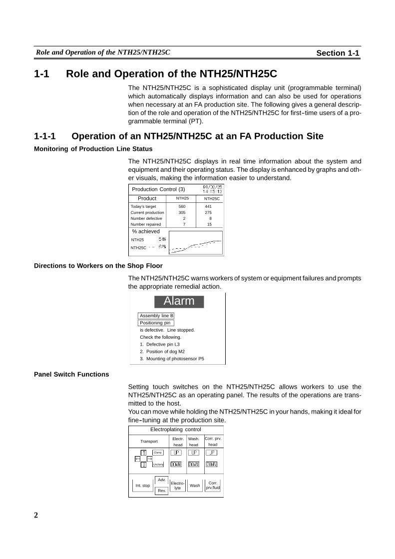
1-1-1 Operation of an NTH25/NTH25C at an FA Production SiteMonitoring of Production Line Status
The NTH25/NTH25C displays in real time information about the system andequipment and their operating status. The display is enhanced by graphs and oth-er visuals, making the information easier to understand.
Production Control (3)
Product
% achieved
Today’s target 560 441
Current production 305 275Number defective 2 8Number repaired 7 15
NTH25
NTH25
NTH25C
NTH25C
Directions to Workers on the Shop Floor
The NTH25/NTH25C warns workers of system or equipment failures and promptsthe appropriate remedial action.
AlarmAssembly line B
Positioning pin
is defective. Line stopped.
Check the following.
1. Defective pin L3
2. Position of dog M2
3. Mounting of photosensor P5
Panel Switch Functions
Setting touch switches on the NTH25/NTH25C allows workers to use theNTH25/NTH25C as an operating panel. The results of the operations are trans-mitted to the host.You canmove while holding the NTH25/NTH25C in your hands, making it ideal forfine--tuning at the production site.
Electroplating control
TransportElectr.
head
Wash.
head
Corr. prv.
head
Clamp
Unclamp
Int. stopAdv.
Rev.
Electro-lyte Wash
Corr.prv.fluid
3
Role and Operation of the NTH25/NTH25C Section 1-1
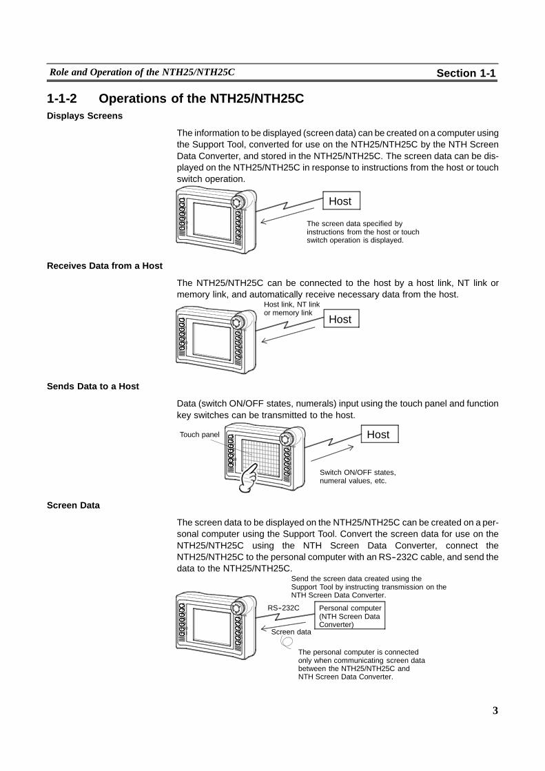
1-1-2 Operations of the NTH25/NTH25CDisplays Screens
The information to be displayed (screen data) can be created on a computer usingthe Support Tool, converted for use on the NTH25/NTH25C by the NTH ScreenData Converter, and stored in the NTH25/NTH25C. The screen data can be dis-played on the NTH25/NTH25C in response to instructions from the host or touchswitch operation.
Host
The screen data specified byinstructions from the host or touchswitch operation is displayed.
+--F7F8F9F10F11
POWERF1F2F3F4F5F6
Receives Data from a Host
The NTH25/NTH25C can be connected to the host by a host link, NT link ormemory link, and automatically receive necessary data from the host.
Host+--F7F8F9F10F11
POWERF1F2F3F4F5F6
Host link, NT linkor memory link
Sends Data to a Host
Data (switch ON/OFF states, numerals) input using the touch panel and functionkey switches can be transmitted to the host.
Host+--F7F8F9F10F11
POWERF1F2F3F4F5F6
Touch panel
Switch ON/OFF states,numeral values, etc.
Screen Data
The screen data to be displayed on the NTH25/NTH25C can be created on a per-sonal computer using the Support Tool. Convert the screen data for use on theNTH25/NTH25C using the NTH Screen Data Converter, connect theNTH25/NTH25C to the personal computer with an RS--232C cable, and send thedata to the NTH25/NTH25C.
Personal computer(NTH Screen DataConverter)
The personal computer is connectedonly when communicating screen databetween the NTH25/NTH25C andNTH Screen Data Converter.
Send the screen data created using theSupport Tool by instructing transmission on theNTH Screen Data Converter.
+--F7F8F9F10F11
POWERF1F2F3F4F5F6
RS--232C
Screen data
4
Functions of the NTH25/NTH25C Section 1-2
1-2 Functions of the NTH25/NTH25CThe NTH25/NTH25C has the following features.
1-2-1 FeaturesHandy PT
! Need not be mounted on operation panels.
! Easy to connect. Only connectors are needed.
Downsized Body
! Slim and light body
! The communications cable and power cable are integrated in a single, slimcable, facilitating cable laying.
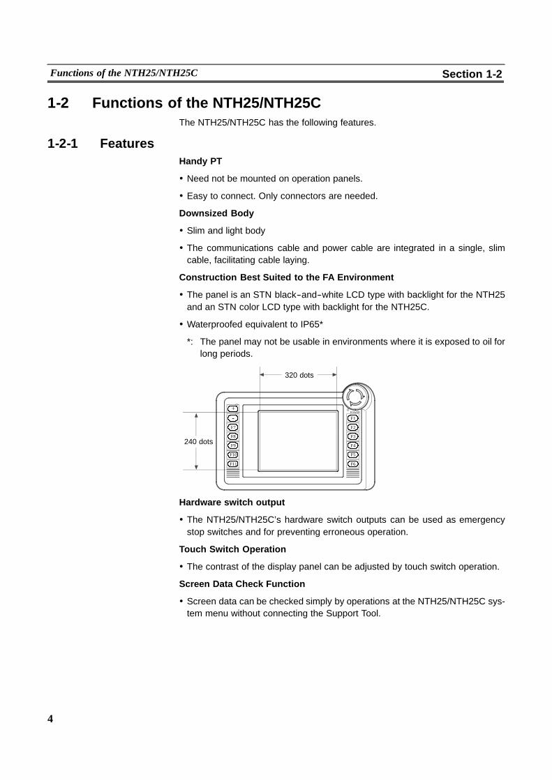
Construction Best Suited to the FA Environment
! The panel is an STN black--and--white LCD type with backlight for the NTH25and an STN color LCD type with backlight for the NTH25C.
! Waterproofed equivalent to IP65*
*: The panel may not be usable in environments where it is exposed to oil forlong periods.
240 dots
320 dots
+--
F7
F8
F9
F10
F11
POWER
F1
F2
F3
F4
F5
F6
Hardware switch output
! The NTH25/NTH25C’s hardware switch outputs can be used as emergencystop switches and for preventing erroneous operation.
Touch Switch Operation
! The contrast of the display panel can be adjusted by touch switch operation.
Screen Data Check Function
! Screen data can be checked simply by operations at the NTH25/NTH25C sys-tem menu without connecting the Support Tool.
5
Functions of the NTH25/NTH25C Section 1-2
Binary Data can be Read to/Written from the Host
! It is now possible to write binary data stored in words on the host directly to theNTH25/NTH25C. This makes data conversion by a program at the host unnec-essary, reducing the load on the host.
Complies with International Standards
! The NTH25/NTH25C meets UL standards and EC directives.
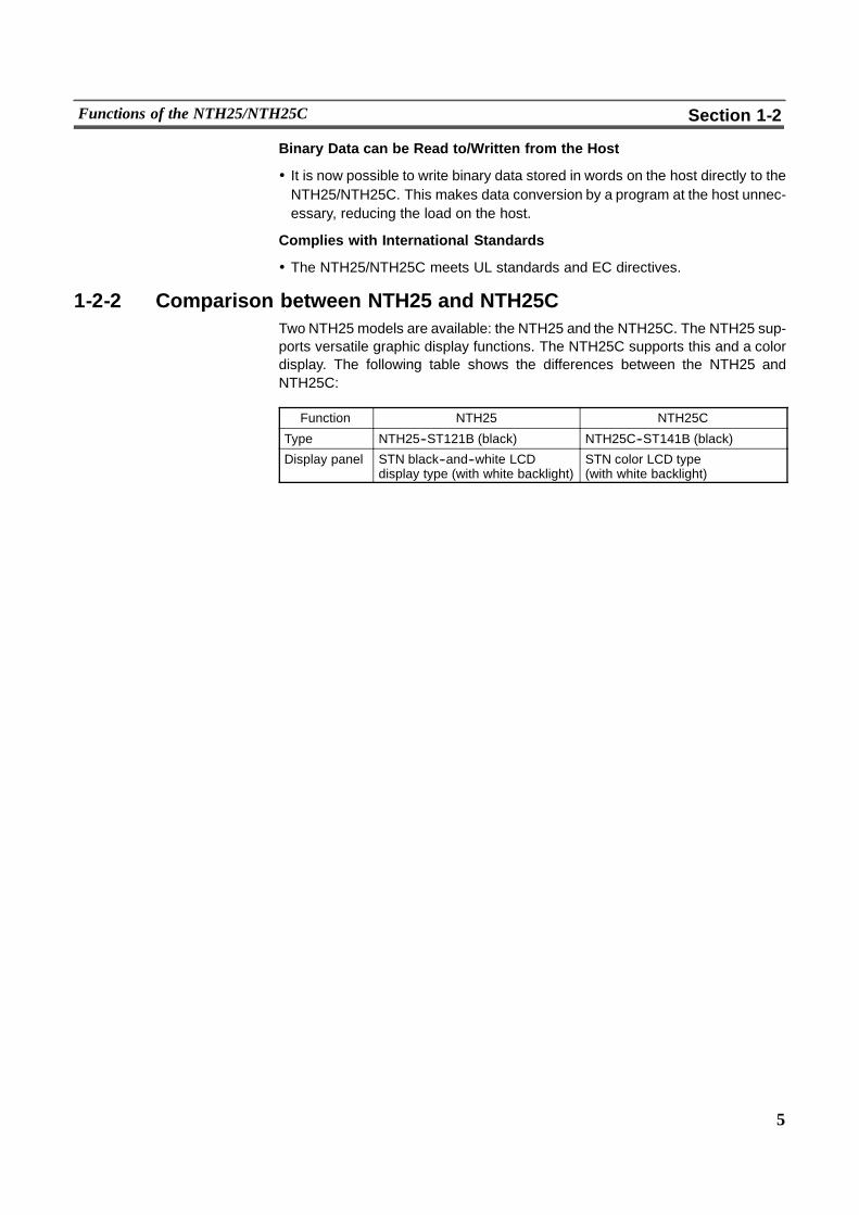
1-2-2 Comparison between NTH25 and NTH25CTwo NTH25 models are available: the NTH25 and the NTH25C. The NTH25 sup-ports versatile graphic display functions. The NTH25C supports this and a colordisplay. The following table shows the differences between the NTH25 andNTH25C:
Function NTH25 NTH25C
Type NTH25--ST121B (black) NTH25C--ST141B (black)
Display panel STN black--and--white LCDdisplay type (with white backlight)
STN color LCD type(with white backlight)
6
Functions of the NTH25/NTH25C Section 1-2
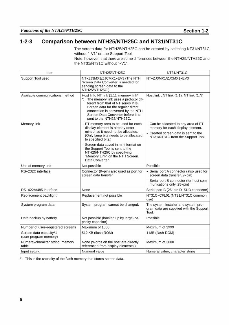
1-2-3 Comparison between NTH25/NTH25C and NT31/NT31CThe screen data for NTH25/NTH25C can be created by selecting NT31/NT31Cwithout “--V1” on the Support Tool.Note, however, that there are some differences between the NTH25/NTH25C andthe NT31/NT31C without “--V1”.
Item NTH25/NTH25C NT31/NT31C
Support Tool used NT--ZJ3MX1/ZJCMX1--EV3 (The NTHScreen Data Converter is needed forsending screen data to theNTH25/NTH25C.)
NT--ZJ3MX1/ZJCMX1--EV3
Available communications method Host link, NT link (1:1), memory link**: The memory link uses a protocol dif-
ferent from that of NT series PTs.Screen data for the regular directconnection is converted by the NTHScreen Data Converter before it issent to the NTH25/NTH25C.
Host link , NT link (1:1), NT link (1:N)
Memory link -- PT memory area to be used for eachdisplay element is already deter-mined, so it need not be allocated.(Only lamp bits needs to be allocatedto specified bits.)
-- Screen data saved in mmi format onthe Support Tool is sent to theNTH25/NTH25C by specifying”Memory Link” on the NTH ScreenData Converter.
-- Can be allocated to any area of PTmemory for each display element.
-- Created screen data is sent to theNT31/NT31C from the Support Tool.
Use of memory unit Not possible Possible
RS--232C interface Connector (9--pin) also used as port forscreen data transfer
-- Serial port A connector (also used forscreen data transfer, 9--pin)
-- Serial port B connector (for host com-munications only, 25--pin)
RS--422A/485 interface None Serial port B (25--pin D--SUB connector)
Replacement backlight Replacement not possible NT31C--CFL01 (NT31/NT31C commonuse)
System program data System program cannot be changed. The system installer and system pro-gram data are supplied with the SupportTool.
Data backup by battery Not possible (backed up by large--ca-pacity capacitor)
Possible
Number of user--registered screens Maximum of 1000 Maximum of 3999
Screen data capacity*1(user program memory)
512 KB (flash ROM) 1 MB (flash ROM)
Numeral/character string memorytable
None (Words on the host are directlyreferenced from display elements.)
Maximum of 2000
Input setting Numeral value Numeral value, character string
*1 This is the capacity of the flash memory that stores screen data.

7
Functions of the NTH25/NTH25C Section 1-2
Item NTH25/NTH25C NT31/NT31C
Graph display Bar graph, trend graph Bar graph, broken--line graph, trendgraph
Indirect reference Not possible Possible
Bit memory table 240 Maximum of 1000
Image data Maximum of 30 (Size is fixed by eachcode number for the image data.)
Maximum of 4095 (Any size can bespecified in multiples of 8 dots.)
Library data Maximum of 3980 Maximum of 12288
PT status control area size 5 words (partial change of contents) 5 words
PT status notify area size 7 words (partial change of contents) 2 words
Window control area Maximum of 20 words (Individual wordscan be set to any area or position by theNTH Screen Data Converter.)
None
Trend graph control area 4 words (Can be set to any area orposition by the NTH Screen Data Con-verter.)
None
Addresses allocatable to control area DM, CH DM, CH, HR, AR, LR
In addition to the above differences, themaximum number of elements that can beregistered and how they are used may also differ.For details on elements, see Section 4 ”NTH25/NTH25C Functions.”For differences in programming, see Appendix F ”Differences with NT31/NT31CScreen Data” on page 303.
! Differences in software and hardware specifications have resulted invarious setting restrictions when using screen data created on the Sup-port Tool on the NTH25/NTH25C. Before you create screen data on theSupport Tool, first check Section 4 ”NTH25/NTH25C Functions” andAp-pendix F ”Differences with NT31/NT31C Screen Data” and create thescreen data taking these restrictions into consideration.
! On the NTH25/NTH25C, thoroughly check the screen data created onthe Support Tool before starting actual operation using that screen data.
8
Functions of the NTH25/NTH25C Section 1-2
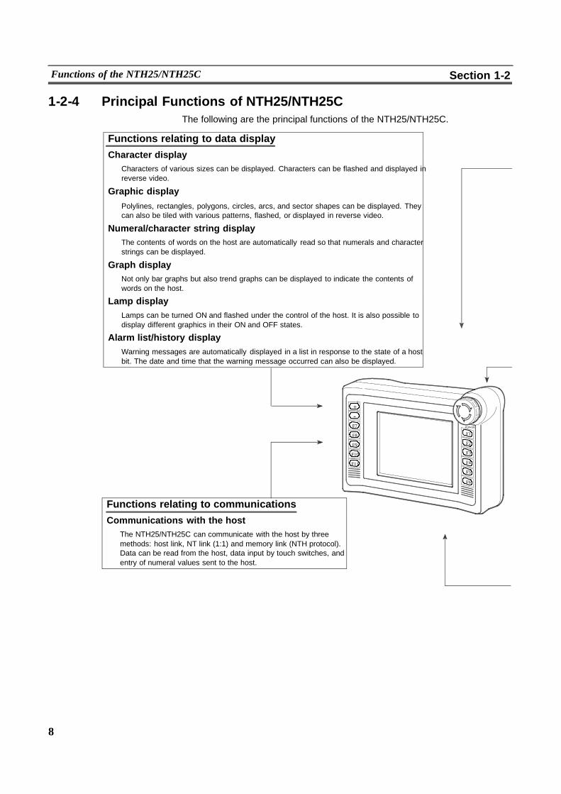
1-2-4 Principal Functions of NTH25/NTH25CThe following are the principal functions of the NTH25/NTH25C.
Functions relating to data display
Character displayCharacters of various sizes can be displayed. Characters can be flashed and displayed inreverse video.
Graphic display
Polylines, rectangles, polygons, circles, arcs, and sector shapes can be displayed. Theycan also be tiled with various patterns, flashed, or displayed in reverse video.
Numeral/character string displayThe contents of words on the host are automatically read so that numerals and characterstrings can be displayed.
Graph displayNot only bar graphs but also trend graphs can be displayed to indicate the contents ofwords on the host.
Lamp displayLamps can be turned ON and flashed under the control of the host. It is also possible todisplay different graphics in their ON and OFF states.
Alarm list/history displayWarning messages are automatically displayed in a list in response to the state of a hostbit. The date and time that the warning message occurred can also be displayed.
Functions relating to communications
Communications with the hostThe NTH25/NTH25C can communicate with the host by threemethods: host link, NT link (1:1) and memory link (NTH protocol).Data can be read from the host, data input by touch switches, andentry of numeral values sent to the host.
+--
F7
F8
F9
F10
F11
POWER
F1
F2
F3
F4
F5
F6

9
Functions of the NTH25/NTH25C Section 1-2
Functions relating to the system
System menuSystem settings and maintenance can be performed by selecting from system menus displayed on the screen.
Creation of screen dataScreen data created using the Support Tool on a personal computer can be converted for use on theNTH25/NTH25C using the NTH Screen Data Converter and stored in the built--in screen data memory.
Clock functionThe time can be measured and output according to the internal clock data.
Programming console functionWhen the NTH25/NTH25C is connected to a C series CPM1, CQM1, or C200HX/HG/HE--(Z)E or SRM1 PC in anNT link (1:1) connection, operations equivalent to those of a programming console (C200H--PR027--E) are pos-sible.
Trend graph logging function and background functionChanges in the contents on the host displayed in trend graphs can be recorded (logging function). Also, the recordcan be maintained even while the trend graph is not displayed (background function).
Functions relating to data input
Input by touch switchesData can be input by simply touching touch switches displayed on the screen.The possible functions of touch switches include sending entered data to the host and switching the screen display.
Input by function switchesPressing a function switch on the NTH25/NTH25C sends the state of that switch to the host regardless of the cur-rently displayed screen.
Pop--up window functionA window overlaying the currently displayed screen can be alternately opened and closed by pressing a touchswitch.In addition to fixed character and graphic displays, control keys and numeral input fields created as touch switchescan also be registered to the window. The screen can be used efficiently since the window need only be openedwhen input is required.
Numeral input functionNumeral keys can be assigned to touch switches so that numerals can be input at the production site. The inputdata is written to words on the host.
Functions relating to data output
Switch outputThe states of the emergency stop switches and two operation switches can beoutput.
10
Functions of the NTH25/NTH25C Section 1-2
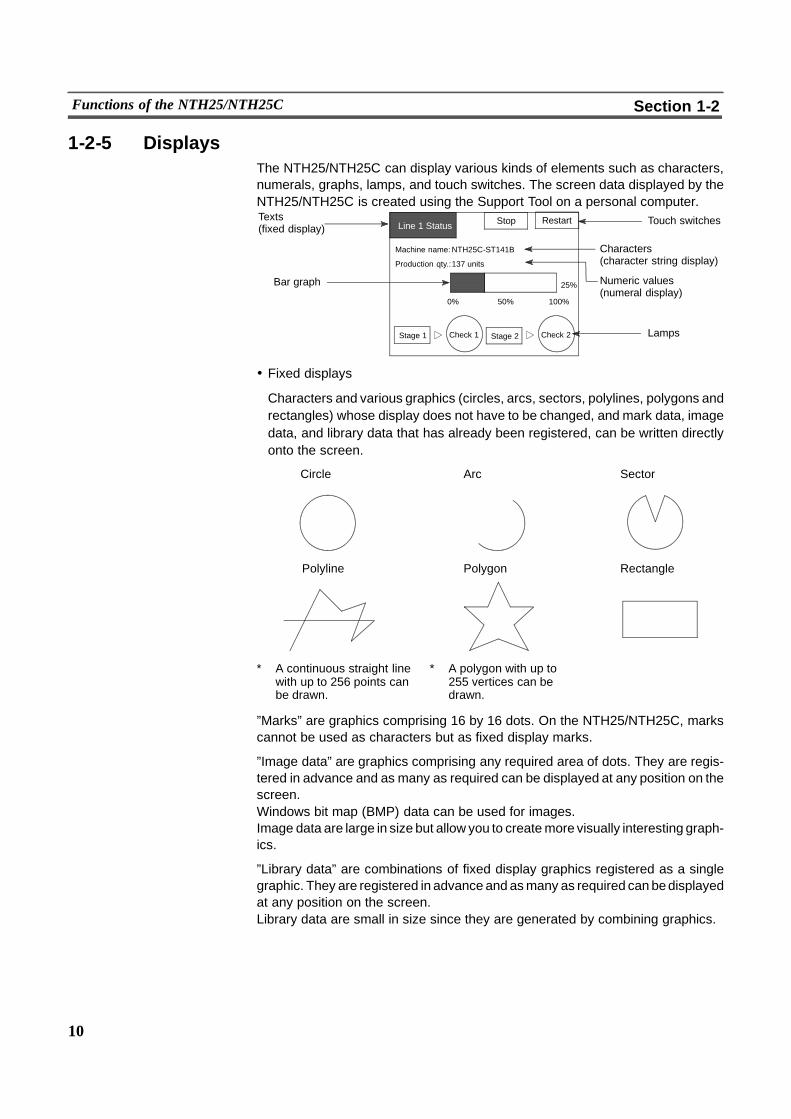
1-2-5 DisplaysThe NTH25/NTH25C can display various kinds of elements such as characters,numerals, graphs, lamps, and touch switches. The screen data displayed by theNTH25/NTH25C is created using the Support Tool on a personal computer.
Lamps
Characters(character string display)
Touch switchesTexts(fixed display)
Bar graph
Line 1 Status Stop Restart
Machine name:NTH25C-ST141B
Production qty.:137 units
Stage 2 Check 2Check 1Stage 1
0% 50% 100%
25% Numeric values(numeral display)
! Fixed displays
Characters and various graphics (circles, arcs, sectors, polylines, polygons andrectangles) whose display does not have to be changed, and mark data, imagedata, and library data that has already been registered, can be written directlyonto the screen.
� Polyline � Polygon � Rectangle
� Circle � Sector� Arc
* A continuous straight linewith up to 256 points canbe drawn.
* A polygon with up to255 vertices can bedrawn.
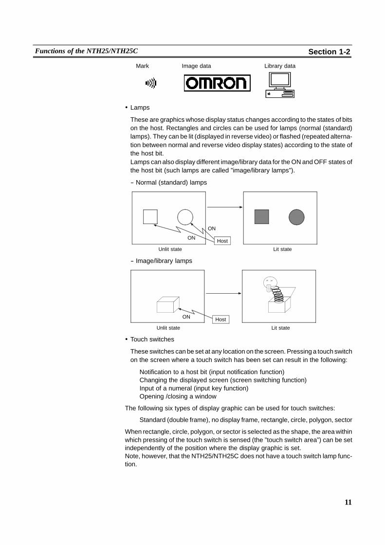
”Marks” are graphics comprising 16 by 16 dots. On the NTH25/NTH25C, markscannot be used as characters but as fixed display marks.
”Image data” are graphics comprising any required area of dots. They are regis-tered in advance and as many as required can be displayed at any position on thescreen.Windows bit map (BMP) data can be used for images.Image data are large in size but allow you to createmore visually interesting graph-ics.
”Library data” are combinations of fixed display graphics registered as a singlegraphic. They are registered in advance and asmany as required can bedisplayedat any position on the screen.Library data are small in size since they are generated by combining graphics.
11
Functions of the NTH25/NTH25C Section 1-2
Mark Image data Library data
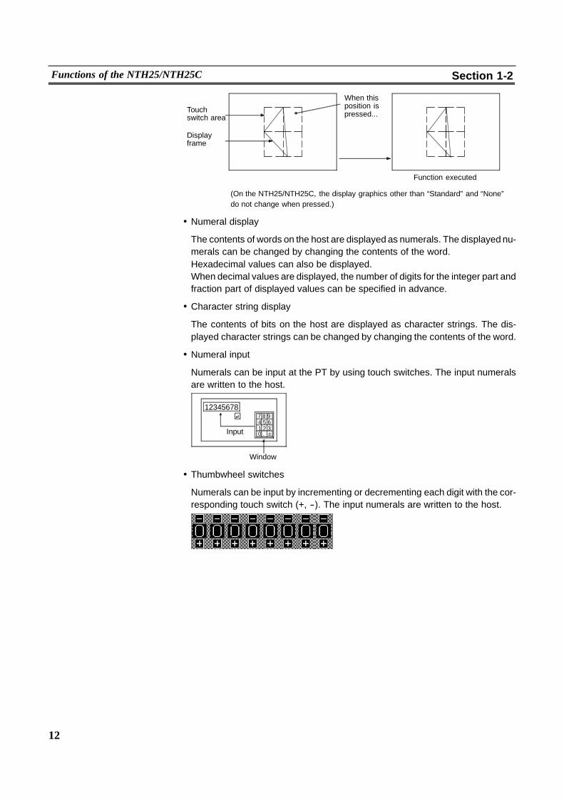
! Lamps
These are graphics whose display status changes according to the states of bitson the host. Rectangles and circles can be used for lamps (normal (standard)lamps). They can be lit (displayed in reverse video) or flashed (repeated alterna-tion between normal and reverse video display states) according to the state ofthe host bit.Lamps can also display different image/library data for theONandOFF states ofthe host bit (such lamps are called ”image/library lamps”).
-- Normal (standard) lamps
ON
ON Host
Unlit state Lit state
-- Image/library lamps
ON
Unlit state Lit state
Host
! Touch switches
These switches can be set at any location on the screen. Pressinga touchswitchon the screen where a touch switch has been set can result in the following:
Notification to a host bit (input notification function)Changing the displayed screen (screen switching function)Input of a numeral (input key function)Opening /closing a window
The following six types of display graphic can be used for touch switches:
Standard (double frame), no display frame, rectangle, circle, polygon, sector
When rectangle, circle, polygon, or sector is selected as the shape, the areawithinwhich pressing of the touch switch is sensed (the ”touch switch area”) can be setindependently of the position where the display graphic is set.Note, however, that the NTH25/NTH25C does not have a touch switch lamp func-tion.
12
Functions of the NTH25/NTH25C Section 1-2
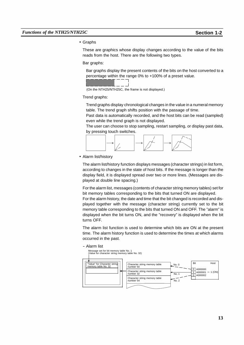
Touchswitch area
When thisposition ispressed...
Displayframe
Function executed
(On the NTH25/NTH25C, the display graphics other than “Standard” and “None”do not change when pressed.)
! Numeral display
The contents of words on the host are displayed as numerals. The displayed nu-merals can be changed by changing the contents of the word.Hexadecimal values can also be displayed.When decimal values are displayed, the number of digits for the integer part andfraction part of displayed values can be specified in advance.
! Character string display
The contents of bits on the host are displayed as character strings. The dis-played character strings can be changed by changing the contents of the word.
! Numeral input
Numerals can be input at the PT by using touch switches. The input numeralsare written to the host.
7 8 94 5 61 2 30 .
12345678
Window
Input
! Thumbwheel switches
Numerals can be input by incrementing or decrementing each digit with the cor-responding touch switch (+, --). The input numerals are written to the host.
13
Functions of the NTH25/NTH25C Section 1-2
! Graphs
These are graphics whose display changes according to the value of the bitsreads from the host. There are the following two types.
Bar graphs:
Bar graphs display the present contents of the bits on the host converted to apercentage within the range 0% to +100% of a preset value.
(On the NTH25/NTH25C, the frame is not displayed.)
Trend graphs:
Trend graphs display chronological changes in the value in a numeralmemorytable. The trend graph shifts position with the passage of time.Past data is automatically recorded, and the host bits can be read (sampled)even while the trend graph is not displayed.The user can choose to stop sampling, restart sampling, or display past data,by pressing touch switches.
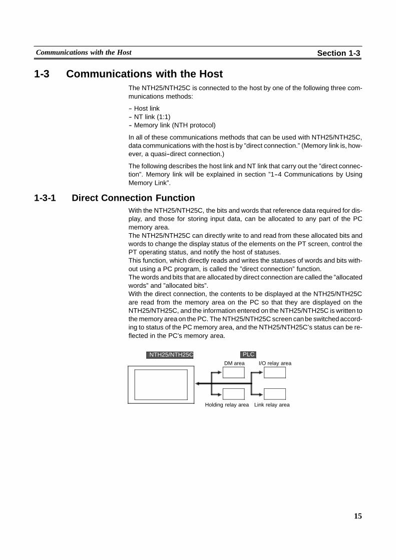
! Alarm list/history
The alarm list/history function displays messages (character strings) in list form,according to changes in the state of host bits. If the message is longer than thedisplay field, it is displayed spread over two or more lines. (Messages are dis-played at double line spacing.)
For the alarm list, messages (contents of character string memory tables) set forbit memory tables corresponding to the bits that turned ON are displayed.For the alarm history, the date and time that the bit changed is recorded and dis-played together with the message (character string) currently set to the bitmemory table corresponding to the bits that turned ON and OFF. The ”alarm” isdisplayed when the bit turns ON, and the ”recovery” is displayed when the bitturns OFF.
The alarm list function is used to determine which bits are ON at the presenttime. The alarm history function is used to determine the times at which alarmsoccurred in the past.
-- Alarm list
“Value” for Character stringmemory table No. 32
Character string memory tablenumber 50
Character string memory tablenumber 32
Character string memory tablenumber 54
BitNo. 0
" 1 (ON)No. 1
No. 2
0 A0000001 A0000010 A000002
Host
Message set for bit memory table No. 1(Value for character string memory table No. 32)

14
Functions of the NTH25/NTH25C Section 1-2
-- Alarm history
Character string memory tablenumber 11
Character string memory tablenumber 12
Character string memory tablenumber 13
No. 22 Bit memory table 2497/12/04 11:19:20ON�Bit memory table 2397/12/04 11:25:12 ON
No. 23
No. 24
Message set for bit memory table No. 24(Value for character string memory table No. 13)
Alarm 12/04 11:19 “Value”for character string memorytable No.13Alarm 12/04 11:25 “Value”for character string memorytable No.12
Record data
15
Communications with the Host Section 1-3
1-3 Communications with the HostThe NTH25/NTH25C is connected to the host by one of the following three com-munications methods:
-- Host link-- NT link (1:1)-- Memory link (NTH protocol)
In all of these communications methods that can be used with NTH25/NTH25C,data communications with the host is by ”direct connection.” (Memory link is, how-ever, a quasi--direct connection.)
The following describes the host link and NT link that carry out the ”direct connec-tion”. Memory link will be explained in section ”1--4 Communications by UsingMemory Link”.
1-3-1 Direct Connection FunctionWith the NTH25/NTH25C, the bits and words that reference data required for dis-play, and those for storing input data, can be allocated to any part of the PCmemory area.The NTH25/NTH25C can directly write to and read from these allocated bits andwords to change the display status of the elements on the PT screen, control thePT operating status, and notify the host of statuses.This function, which directly reads and writes the statuses of words and bits with-out using a PC program, is called the ”direct connection” function.The words and bits that are allocated by direct connection are called the ”allocatedwords” and ”allocated bits”.With the direct connection, the contents to be displayed at the NTH25/NTH25Care read from the memory area on the PC so that they are displayed on theNTH25/NTH25C, and the information entered on the NTH25/NTH25C is written tothememory area on the PC. TheNTH25/NTH25C screen canbe switchedaccord-ing to status of the PC memory area, and the NTH25/NTH25C’s status can be re-flected in the PC’s memory area.
DM area I/O relay area
Holding relay area Link relay area
PLCNTH25/NTH25C
16
Communications with the Host Section 1-3
Features of the Direct Connection Function
The direct connection function has the following features:
- The bits and words for referencing the operating status and work instruction in-formation and those for storing input data can be freely allocated to any area ofPC memory.
- Since the NTH25/NTH25C can directly reference PC bit and word data withoutusing a PC program, it can be connected to the PCwithout changing the PCpro-gram which controls the currently running production line.
- The area for controlling and notifying the NTH25/NTH25C statuses, includingdisplay screens, and display/no display status, can be freely allocated to anypart of the PC memory area. This means that the PT status can be read andcontrolled just by reading this area at the PC, without preparing a special com-munications program.
The direct connection function allows the NTH25/NTH25C to read and write bitsand words in the PC and to automatically update the NTH25/NTH25C screen dis-play. This function can reduce the load on the PC so that its program developmentefficiency is improved.
1-3-2 Host LinkThe host is connected to a PT in a 1:1 connection, and the words and bits of thehost are read and displayed by host link communications. This method can beused for connection to the majority of PC types.
1-3-3 NT LinkNT link is amethod for high--speed communications with aPCusing the direct con-nection function. The PCs that can be connected to NTH25/NTH25C with the NTlink are as follows:
CPM1, CQM1, C200HS, C200HX/HG/HE(--Z)E, CVM1/CV--series PC (--EV1or later version), SRM1
TheNTH25/NTH25C only supports NT link (1:1).With NT link (1:1), onePT is con-nected to one PC. The NT link (1:N) for connecting two or more PTs to one PC isnot supported.
17
Communications with the Host Section 1-3
Features of the NT Link
- The NT link has the following features:
- High--speed communications with specific types of PCs can be executed.
- Writing in units of bits to the PC memory area is possible.This enables the other bits of words to which a touch switch has been allocatedto be allocated for other purposes (e.g. a lamp).However, since data is written to the DM area in word units, the other bits ofwords allocated to touch switches in this area cannot be used for other pur-poses.
- It is possible to connect to PT without switching the PC operation mode. (Whenthe host link is used, the PC is switched to themonitor modewhen it is in theRUNmode.)
- When using C200HX/HG/HE--(Z)E, up to three NT link (1:1) systems can beconnected by installing a communications board in the option slot of the CPUunit. For details on the communications board, refer to the SYSMAC #Commu-nications Board User’s Manual (SCCC--305 � ).
- If the PC used supports the programming console function, theNTH25/NTH25Ccan be used as a programming console.
The NT link is compatible with the host link. So, the NTH25/NTH25C screen dataandPCprograms usedwith the host link direct connection can be usedwith theNTlink as they are.
1-3-4 Functions of Allocated Bits and WordsElements displayed on the NTH25/NTH25C and the NTH25/NTH25C status canbe allocated to the bits and words of the PCwhenusing the direct connection func-tion. By changing the contents of these bits and words, the NTH25/NTH25C canbe controlled by the PC. It is also possible to send data to the PCby pressing touchswitches at the NTH25/NTH25C.
Controlling the NTH25/NTH25C with a PC
The following NTH25/NTH25C functions can be controlled by a PC.
- Screens:Display of designated screens, confirmation of screen numbers, etc.
- Display details of numerals and character strings:Updating of the contents of numerals, graphs and character strings to be dis-played on the NTH25/NTH25C
- Lamps:Display instructions, confirmation of display status, etc.
- System control:Backlight ON/OFF, instruction of clock data output

18
Communications with the Host Section 1-3
Notifying a PC from the NTH25/NTH25C
Data in the NTH25/NTH25C is sent to a PC when, for example, a touch switch ispressed. The following three types of data are sent to a PC:
- NTH25/NTH25C status, screen number of currently displayed screen
- Touch switch input states
- Numeral value input with the numeral input function using touch switches
Functions of Display Elements
- Lamps (See page 137.)Allocation destination: Bit
Lamp #1 (Bit 000100)
Lamp #2 (Bit 000101)
Switch 1: ON (Bit 000100)
Switch 2: OFF (Bit 000101)
Lit
Unlit
PLCNTH25/NTH25C
The PC’s bit state is displayed by the ”lamp” at the NTH25/NTH25C.Normal (standard) lamps turn on (flash) when the PC’s bit state (lamp bit) is ON(1), and go off when it is OFF (0).With image/library lamps, the displayed image or library data can be switched ac-cording to the ON (1)/OFF (0) state of PC bits (lamp bits).
- Touch switches (See page 145.)Allocation destination: Bit
1009012Touch switch #12Bit 009012
Bit 009012: ON
PLCNTH25/NTH25C
When the touch switch is pressed, the bit (notification bit) allocated to the PC turnsON (1) or goes OFF (0).
19
Communications with the Host Section 1-3
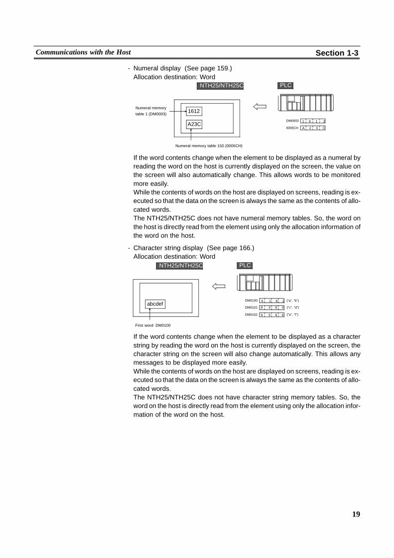
- Numeral display (See page 159.)Allocation destination: Word
1 6 1 2DM0003
1612
A23CA 2 3 C0005CH
Numeral memory
table 1 (DM0003)
Numeral memory table 150 (0005CH)
PLCNTH25/NTH25C
If the word contents change when the element to be displayed as a numeral byreading the word on the host is currently displayed on the screen, the value onthe screen will also automatically change. This allows words to be monitoredmore easily.While the contents of words on the host are displayed on screens, reading is ex-ecuted so that the data on the screen is always the same as the contents of allo-cated words.The NTH25/NTH25C does not have numeral memory tables. So, the word onthe host is directly read from the element using only the allocation information ofthe word on the host.
- Character string display (See page 166.)Allocation destination: Word
6 1 6 2DM0100abcdef
DM0101
DM0102
(“a”, “b”)
(“c”, “d”)
(”e”, “f”)
First word: DM0100
6 3 6 4
6 5 6 6
PLCNTH25/NTH25C
If the word contents change when the element to be displayed as a characterstring by reading the word on the host is currently displayed on the screen, thecharacter string on the screen will also change automatically. This allows anymessages to be displayed more easily.While the contents of words on the host are displayed on screens, reading is ex-ecuted so that the data on the screen is always the same as the contents of allo-cated words.The NTH25/NTH25C does not have character string memory tables. So, theword on the host is directly read from the element using only the allocation infor-mation of the word on the host.
20
Communications with the Host Section 1-3
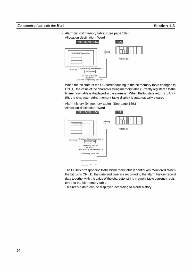
- Alarm list (bit memory table) (See page 189.)Allocation destination: Word
1010009
Material low
Alarm listCharacter string memory table 120
Material low
Bit memory table 23Bit 010009
Character string memory table 120
PLCNTH25/NTH25C
When the bit state of the PC corresponding to the bit memory table changes toON (1), the value of the character string memory table currently registered to thebit memory table is displayed in the alarm list. When the bit state returns to OFF(0), the character string memory table display is automatically cleared.
- Alarm history (bit memory table) (See page 189.)Allocation destination: Word
1015012
Water temp. high
Alarm historyCharacter string memory table 134
Water temp. high
Bit memory table 52Bit 015012
Character string memory table 134
Alarm history record data
PLCNTH25/NTH25C
ThePCbit corresponding to the bit memory table is continually monitored.Whenthe bit turns ON (1), the date and time are recorded to the alarm history recorddata together with the value of the character string memory table currently regis-tered to the bit memory table.This record data can be displayed according to alarm history.

21
Communications with the Host Section 1-3
Functions of the PT Status Control Area (PC $ PT)
The ”PT status control area” is used to control the NTH25/NTH25C status. Whendata is written to this area on the PC, the NTH25/NTH25C reads the contents ofthis area and operates according to the contents.
[Example of PT status control area application]When data is written to the PT status control area, the NTH25/NTH25C operatesas follows (page 90).
System reserve
PT status control area
Clock data
Screen No.3 000000000021 PT status control bits
Screen switch settingSystem reserve
Output to the host
0003
System reserve0000
PLCNTH25/NTH25C
Functions of the PT Status Notify Area (PT to PC)
The ”PT status notify area” is used to notify the changes in the NTH25/NTH25Cstatus.When the NTH25/NTH25C status changes, this change in status is written to thePT status notify area on the PC. The NTH25/NTH25C status can be checked byreading the data from this area.
[Example of PT status notify area application]When the NTH25/NTH25C status changes, this change in status is notified to thePT status notify area as follows (page 93):
12345678PT status notify area
PT status0801
System reserve0000
PLCNTH25/NTH25C
7 8 94 5 61 2 3
5 6 7 81 2 3 4
12345678�
Allocated word (numeral table 13)
StartStart + 1
0 .
22
Communications by Using Memory Link Section 1-4
1-4 Communications by Using Memory LinkThis section describes a communications method other than direct connection,called the ”memory link”.
1-4-1 Memory LinkMemory link is a means of sending and receiving data between a personal com-puter or an FA computer and the NTH25/NTH25C over the RS--232C interface.
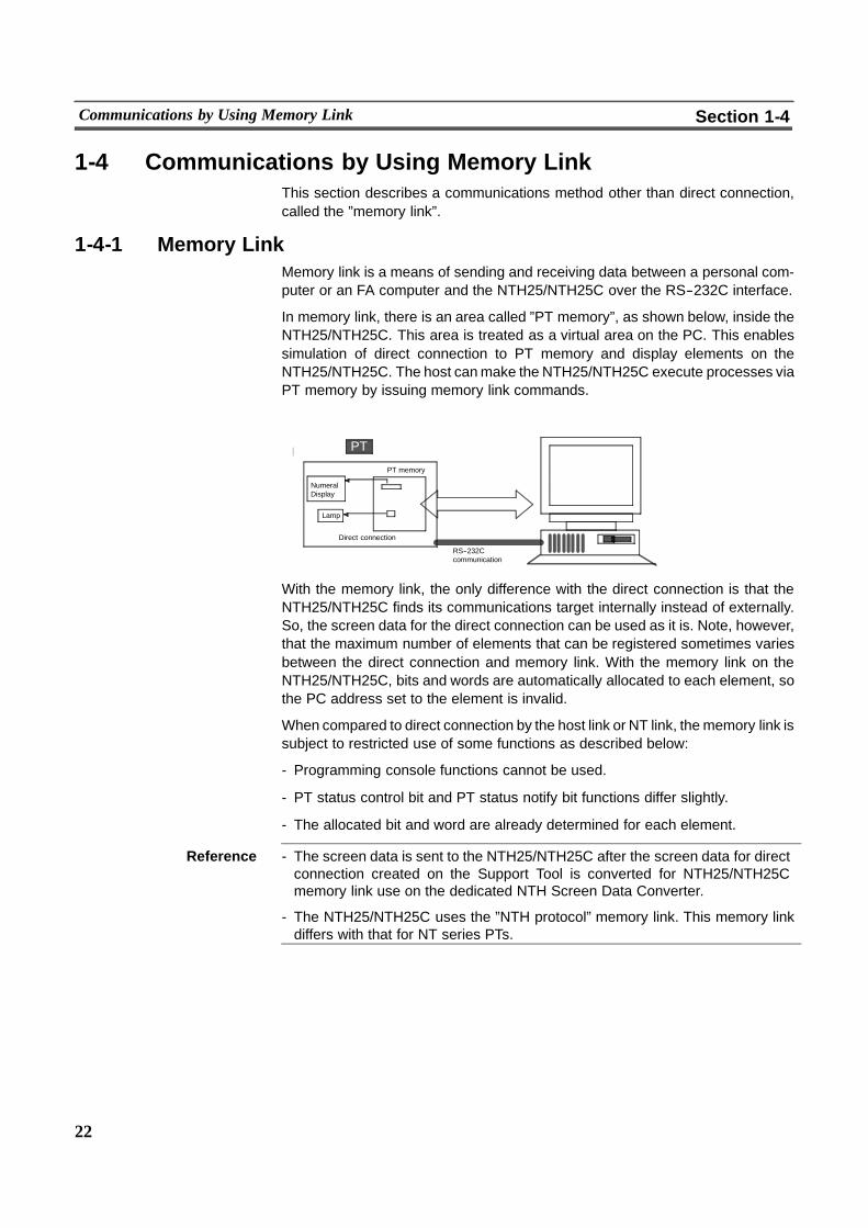
In memory link, there is an area called ”PT memory”, as shown below, inside theNTH25/NTH25C. This area is treated as a virtual area on the PC. This enablessimulation of direct connection to PT memory and display elements on theNTH25/NTH25C. The host canmake the NTH25/NTH25C execute processes viaPT memory by issuing memory link commands.
Lamp
PT memory
PT
RS--232Ccommunication
PCNT31/NT31C
Direct connection
NumeralDisplay
With the memory link, the only difference with the direct connection is that theNTH25/NTH25C finds its communications target internally instead of externally.So, the screen data for the direct connection can be used as it is. Note, however,that the maximum number of elements that can be registered sometimes variesbetween the direct connection and memory link. With the memory link on theNTH25/NTH25C, bits and words are automatically allocated to each element, sothe PC address set to the element is invalid.
When compared to direct connection by the host link or NT link, the memory link issubject to restricted use of some functions as described below:
- Programming console functions cannot be used.
- PT status control bit and PT status notify bit functions differ slightly.
- The allocated bit and word are already determined for each element.
Reference - The screen data is sent to the NTH25/NTH25C after the screen data for directconnection created on the Support Tool is converted for NTH25/NTH25Cmemory link use on the dedicated NTH Screen Data Converter.
- The NTH25/NTH25C uses the ”NTH protocol” memory link. This memory linkdiffers with that for NT series PTs.
23
Communications by Using Memory Link Section 1-4
1-4-2 Comparison between Direct Connection and Memory LinkThe two major differences between direct connection and memory link are as fol-lows:
a) With the memory link, communications with the host must be carried out by us-ing commands. Compared with regular direct connection, which can be usedrequiring almost no programs, memory link requires a program for executingcommand transactions. This, however, allows the PT to be used in a widerrange of applications as a large variety of functions available in the direct con-nection can be used from numerous equipment such as personal computersand FA computers supporting the RS--232C interface.
b) As PT memory area to be used for each element is already determined, the PCaddress currently set to elements is invalid.When PTmemory area is read andwritten from the host, the address already determined for each element is ac-cessed regardless of the currently set PC address.
For details on communications between the host and the PT by the memory link,see Section 5 ”Using Memory Link (NTH Protocol)”. For details on how to usescreens and display elements, see Section 4 ”NTH25/NTH25C Functions”.
24
System Configuration Section 1-5
1-5 System ConfigurationThis section shows the configuration of a system that uses an NTH25/NTH25C.For details on product models, see Appendix G ”Model List” (page 316).
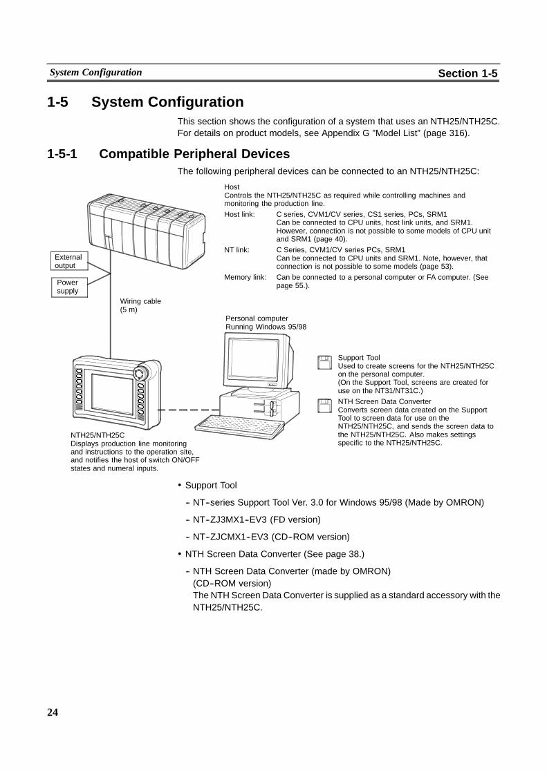
1-5-1 Compatible Peripheral DevicesThe following peripheral devices can be connected to an NTH25/NTH25C:
Personal computerRunning Windows 95/98
Support ToolUsed to create screens for the NTH25/NTH25Con the personal computer.(On the Support Tool, screens are created foruse on the NT31/NT31C.)NTH Screen Data ConverterConverts screen data created on the SupportTool to screen data for use on theNTH25/NTH25C, and sends the screen data tothe NTH25/NTH25C. Also makes settingsspecific to the NTH25/NTH25C.
HostControls the NTH25/NTH25C as required while controlling machines andmonitoring the production line.Host link: C series, CVM1/CV series, CS1 series, PCs, SRM1
Can be connected to CPU units, host link units, and SRM1.However, connection is not possible to some models of CPU unitand SRM1 (page 40).
NT link: C Series, CVM1/CV series PCs, SRM1Can be connected to CPU units and SRM1. Note, however, thatconnection is not possible to some models (page 53).
Memory link: Can be connected to a personal computer or FA computer. (Seepage 55.).
NTH25/NTH25CDisplays production line monitoringand instructions to the operation site,and notifies the host of switch ON/OFFstates and numeral inputs.
�
Wiring cable(5 m)
Powersupply
Externaloutput
! Support Tool
-- NT--series Support Tool Ver. 3.0 for Windows 95/98 (Made by OMRON)
-- NT--ZJ3MX1--EV3 (FD version)
-- NT--ZJCMX1--EV3 (CD--ROM version)
! NTH Screen Data Converter (See page 38.)
-- NTH Screen Data Converter (made by OMRON)(CD--ROM version)The NTH Screen Data Converter is supplied as a standard accessory with theNTH25/NTH25C.
25
System Configuration Section 1-5
1-5-2 Connecting to the HostA dedicated communications connector (D--SUB 9--pin) is attached to theNTH25/NTH25C’s cable. Use this connector to connect the NTH25/NTH25C tothe host.The NTH25/NTH25C’s cable also divides into the control/power supply connector10 cm from its tip. Use this connector, for example, to supply power and outputswitch states.For details on connections, see 2--5 ”Connecting to the Host”.

26
Before Operating the NTH25/NTH25C Section 1-6
1-6 Before Operating the NTH25/NTH25CFollow the procedure below to start the NTH25/NTH25C system:
Host NTH25/NTH25C Personal computer
Settings on host Install the Support Toolat the computer.
Settings in CHECK menu
Connect the power supply.(See page 34.)
(Refer to the manual forthe Support Tool.)
Create the screens.(See Sections 4 and 5 and theSupport Tool manual.)
(See page 250.)
Convert and transmit the screen data. (See page 65.)
Connect to the host.
(See page 40.)
Confirm the settings andcheck communications.
-- For the host link,see page 40 and themanuals for the hostlink unit andperipheral tools.
-- For the NT link(1:1), see page 53.
-- For the Memory link,see page 55.
Connect to theNTH25/NTH25C.
Create the hostprogram.
Start operation.
*1
Install NTH ScreenData Converter on thepersonal computer.
Make the settings specificto the NTH25/NTH25C.
(See Section 6.)
(See Section 3)
(See page 73.)
*2
*3
*1 On the NTH25/NTH25C, only the setting made in the CHECK menu is valid as theclock data.
*2 On the Support Tool, set the PT type to ”NT31” or ”NT31C” when you create screendata for the NTH25 and NTH25C, respectively. (NTH25 and NTH25C cannot be setdirectly on the Support Tool.) Do not, however, set ”NT31--V1” or ”NT31C--V1”.Also, save the screen data created on the Support Tool only in the mmi format. Otherformat data such as the onw regular save format cannot be read by the NTH ScreenData Converter.
*3 mmi format screen data created on the Support Tool is read, and settings specific tothe NTH25/NTH25C are made. On the NTH25/NTH25C, the communicationsmethod settings and PT type (NTH25/NTH25C) settings are both made in the NTHScreen Data Converter.
Reference - For the Support Tool, use NT--series Support Tool for Windows 95/98 (Ver.3.0.).
- NTH Screen Data Converter is provided with the NTH25/NTH25C.
27
Before Operating the NTH25/NTH25C Section 1-6
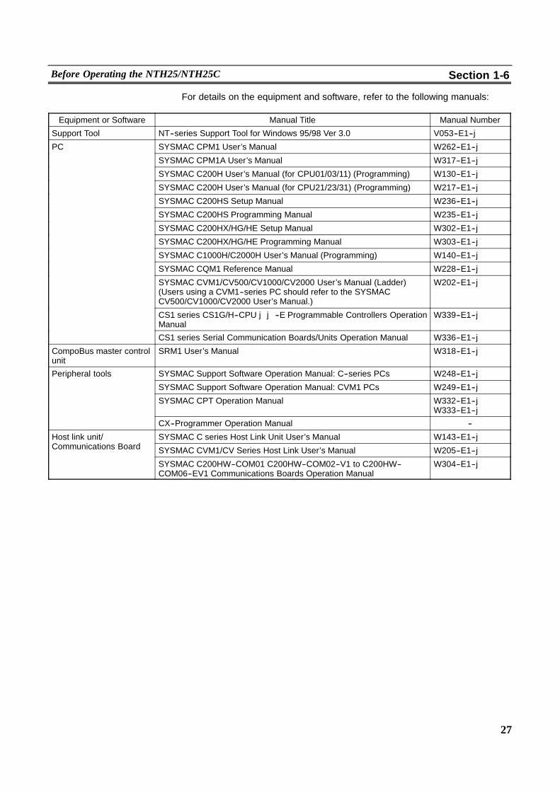
For details on the equipment and software, refer to the following manuals:
Equipment or Software Manual Title Manual Number
Support Tool NT--series Support Tool for Windows 95/98 Ver 3.0 V053--E1--j
PC SYSMAC CPM1 User’s Manual W262--E1--j
SYSMAC CPM1A User’s Manual W317--E1--j
SYSMAC C200H User’s Manual (for CPU01/03/11) (Programming) W130--E1--j
SYSMAC C200H User’s Manual (for CPU21/23/31) (Programming) W217--E1--j
SYSMAC C200HS Setup Manual W236--E1--j
SYSMAC C200HS Programming Manual W235--E1--j
SYSMAC C200HX/HG/HE Setup Manual W302--E1--j
SYSMAC C200HX/HG/HE Programming Manual W303--E1--j
SYSMAC C1000H/C2000H User’s Manual (Programming) W140--E1--j
SYSMAC CQM1 Reference Manual W228--E1--j
SYSMAC CVM1/CV500/CV1000/CV2000 User’s Manual (Ladder)(Users using a CVM1--series PC should refer to the SYSMACCV500/CV1000/CV2000 User’s Manual.)
W202--E1--j
CS1 series CS1G/H--CPU jj--E Programmable Controllers OperationManual
W339--E1--j
CS1 series Serial Communication Boards/Units Operation Manual W336--E1--j
CompoBus master controlunit
SRM1 User’s Manual W318--E1--j
Peripheral tools SYSMAC Support Software Operation Manual: C--series PCs W248--E1--jp
SYSMAC Support Software Operation Manual: CVM1 PCs W249--E1--j
SYSMAC CPT Operation Manual W332--E1--jW333--E1--j
CX--Programmer Operation Manual --
Host link unit/C
SYSMAC C series Host Link Unit User’s Manual W143--E1--j/Communications Board SYSMAC CVM1/CV Series Host Link User’s Manual W205--E1--j
SYSMAC C200HW--COM01 C200HW--COM02--V1 to C200HW--COM06--EV1 Communications Boards Operation Manual
W304--E1--j
29
SECTION 2Connection
This section describes the possible connection methods with the NTH25/NTH25C, and the functions of parts on theNTH25/NTH25C. This knowledge is required before connecting to the host and to peripheral devices.This section also describes the operating environment for the NTH25/NTH25C, and how to connect to the host and the NTHScreen Data Converter running on the personal computer.
2-1 Method for Connection to the Host 30. . . . . . . . . . . . . . . . . . . . . . . . . . . . . . . . . . . . . . . . . . . . . .2-1-1 Connection Method and Communications Method 30. . . . . . . . . . . . . . . . . . . . . . . . . . . . .
2-2 Names and Functions of Parts 32. . . . . . . . . . . . . . . . . . . . . . . . . . . . . . . . . . . . . . . . . . . . . . . . . . .2-2-1 Installation Environment 32. . . . . . . . . . . . . . . . . . . . . . . . . . . . . . . . . . . . . . . . . . . . . . . . .2-2-2 Front View 33. . . . . . . . . . . . . . . . . . . . . . . . . . . . . . . . . . . . . . . . . . . . . . . . . . . . . . . . . . . .2-2-3 Rear View 33. . . . . . . . . . . . . . . . . . . . . . . . . . . . . . . . . . . . . . . . . . . . . . . . . . . . . . . . . . . . .
2-3 Wiring Cable Functions and Connections 34. . . . . . . . . . . . . . . . . . . . . . . . . . . . . . . . . . . . . . . . .2-3-1 Connecting the control/power supply connector 34. . . . . . . . . . . . . . . . . . . . . . . . . . . . . . .2-3-2 Connecting the 9--pin D--SUB Connector 37. . . . . . . . . . . . . . . . . . . . . . . . . . . . . . . . . . . .2-3-3 Grounding 37. . . . . . . . . . . . . . . . . . . . . . . . . . . . . . . . . . . . . . . . . . . . . . . . . . . . . . . . . . . .
2-4 Connecting to the NTH Screen Data Converter 38. . . . . . . . . . . . . . . . . . . . . . . . . . . . . . . . . . . . .2-4-1 Connection Method 39. . . . . . . . . . . . . . . . . . . . . . . . . . . . . . . . . . . . . . . . . . . . . . . . . . . . .
2-5 Connecting to the Host 40. . . . . . . . . . . . . . . . . . . . . . . . . . . . . . . . . . . . . . . . . . . . . . . . . . . . . . . .2-5-1 Host Types and Settings 40. . . . . . . . . . . . . . . . . . . . . . . . . . . . . . . . . . . . . . . . . . . . . . . . . .2-5-2 Connections 56. . . . . . . . . . . . . . . . . . . . . . . . . . . . . . . . . . . . . . . . . . . . . . . . . . . . . . . . . . .

30
Method for Connection to the Host Section 2-1
2-1 Method for Connection to the HostThis section describes the methods for connecting to the host used with theNTH25/NTH25C, and the relationship between the connection method and thecommunications method.
2-1-1 Connection Method and Communications Method! NTH25/NTH25C communications ports and communications methods
The NTH25/NTH25C has one communications port which is used as follows:
CommunicationsPort
Available CommunicationsMethods Communications Type
Serial port
Host linkNT link (1:1)Memory link (NTH protocol)(NTH Screen Data Converterconnection)
RS--232C
! Available communications methods with the host
The following communications method can be used with hosts that are compat-ible with the NTH25/NTH25C:
-- RS--232C
The communications type that is actually supported varies according to thehost.For details, see 2--5 ”Connecting to the Host”.
! Converting the communications typewith anRS--232C/RS--422A converter unit
The communications type can be converted as follows by using anRS--232C/RS--422A converter unit (NT--AL001, made by OMRON).
-- (NTH25/NTH25C side) RS--232C$ Converter unit$ RS--422A (Host side)
31
Method for Connection to the Host Section 2-1
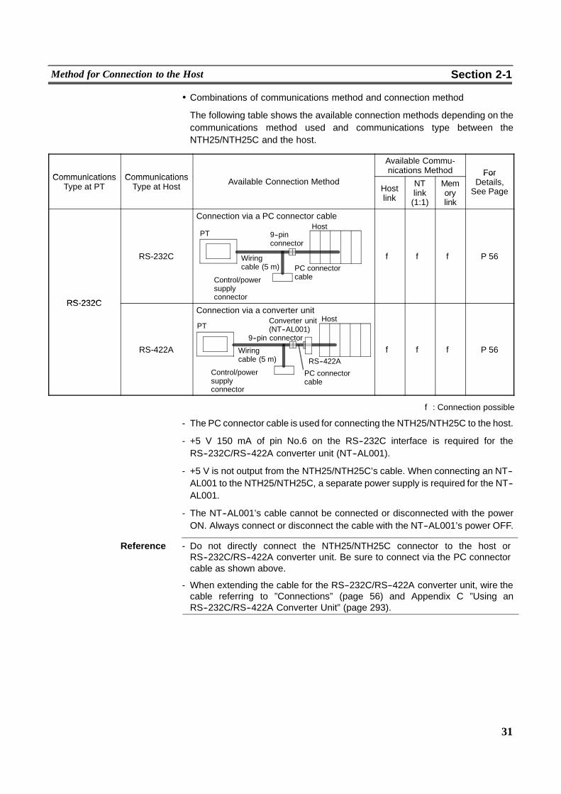
! Combinations of communications method and connection method
The following table shows the available connection methods depending on thecommunications method used and communications type between theNTH25/NTH25C and the host.
Communications Communications
Available Commu-nications Method ForCommunications
Type at PTCommunicationsType at Host Available Connection Method
Hostlink
NTlink(1:1)
Memorylink
ForDetails,See Page
RS 232C
RS-232C
Connection via a PC connector cable
PT 9--pinconnector
Wiringcable (5 m)
Control/powersupplyconnector
Host
PC connectorcable
f f f P 56
RS-232C
RS-422A
PTConverter unit(NT--AL001)
Wiringcable (5 m)
Control/powersupplyconnector
Host
PC connectorcable
RS--422A
Connection via a converter unit
9--pin connector
f f f P 56
f: Connection possible
- The PC connector cable is used for connecting the NTH25/NTH25C to the host.
- +5 V 150 mA of pin No.6 on the RS--232C interface is required for theRS--232C/RS--422A converter unit (NT--AL001).
- +5 V is not output from the NTH25/NTH25C’s cable. When connecting an NT--AL001 to the NTH25/NTH25C, a separate power supply is required for the NT--AL001.
- The NT--AL001’s cable cannot be connected or disconnected with the powerON. Always connect or disconnect the cable with the NT--AL001’s power OFF.
Reference - Do not directly connect the NTH25/NTH25C connector to the host orRS--232C/RS--422A converter unit. Be sure to connect via the PC connectorcable as shown above.
- When extending the cable for the RS--232C/RS--422A converter unit, wire thecable referring to ”Connections” (page 56) and Appendix C ”Using anRS--232C/RS--422A Converter Unit” (page 293).
32
Names and Functions of Parts Section 2-2
2-2 Names and Functions of PartsThis section describes the operating environment for the NTH25/NTH25C, andthe names and functions of parts.
Caution When unpacking the NTH25/NTH25C and peripheral devices, check their exter-nal appearance and confirm that they are not damaged. Also shake them lightlyand confirm that they do not emit any abnormal noises.
2-2-1 Installation EnvironmentPay attention to the following points when installing the NTH25/NTH25C.
Caution Do not install the NTH25/NTH25C at sites subject to the following:
-- Severe temperature variations-- Temperature or humidity outside the ranges stated in the specifications-- High humidity, condensation-- Splashing chemical agents-- Severe oil splashing-- Corrosive or flammable gases-- Strong vibrations or shocks-- Direct exposure to wind and rain (outdoor sites)-- Strong ultra--violet irradiation
Take adequatemeasures to ensure shielding if the unit is used at a location subjectto the following:
-- Static electricity, or electrical noise from other equipment-- Strong electromagnetic fields-- Nearby power cables-- Potential exposure to radioactivity
33
Names and Functions of Parts Section 2-2
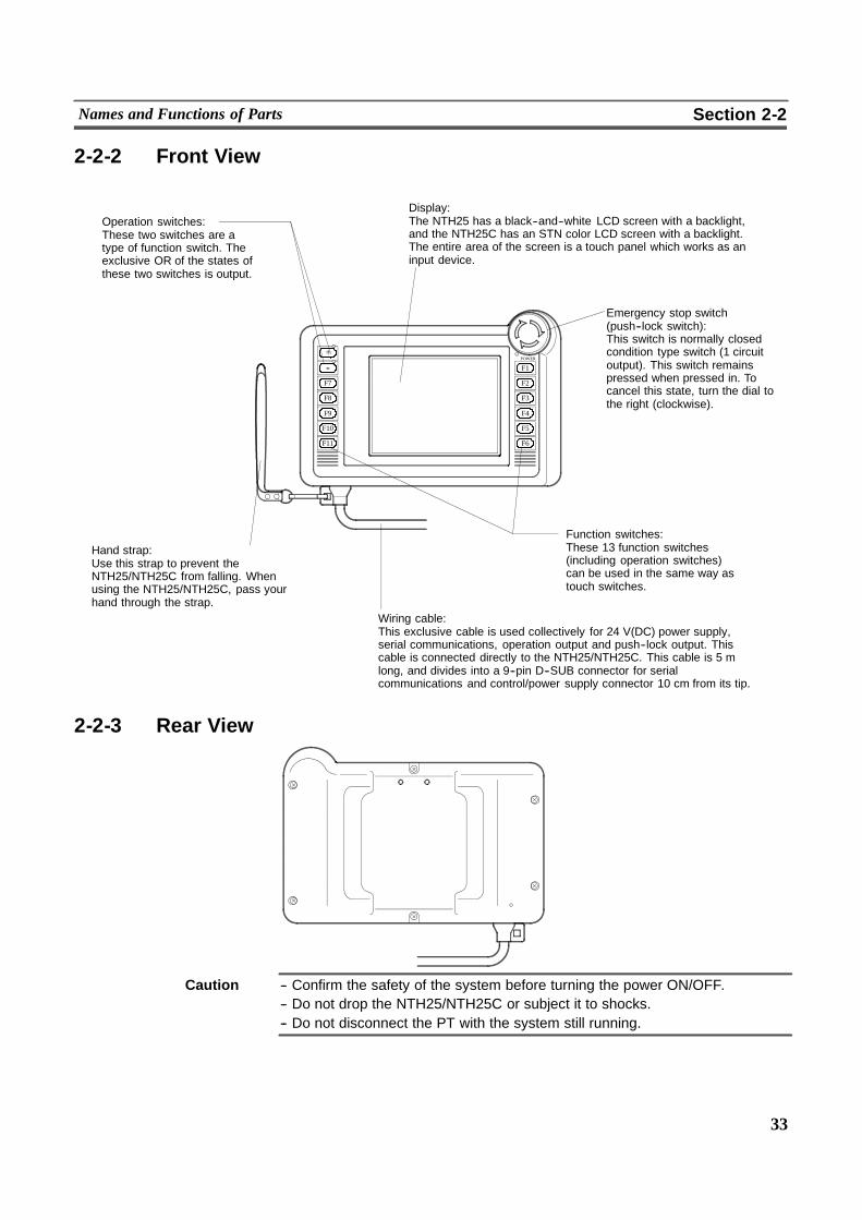
2-2-2 Front View
Display:The NTH25 has a black--and--white LCD screen with a backlight,and the NTH25C has an STN color LCD screen with a backlight.The entire area of the screen is a touch panel which works as aninput device.
Emergency stop switch(push--lock switch):This switch is normally closedcondition type switch (1 circuitoutput). This switch remainspressed when pressed in. Tocancel this state, turn the dial tothe right (clockwise).
Operation switches:These two switches are atype of function switch. Theexclusive OR of the states ofthese two switches is output.
Hand strap:Use this strap to prevent theNTH25/NTH25C from falling. Whenusing the NTH25/NTH25C, pass yourhand through the strap.
Function switches:These 13 function switches(including operation switches)can be used in the same way astouch switches.
Wiring cable:This exclusive cable is used collectively for 24 V(DC) power supply,serial communications, operation output and push--lock output. Thiscable is connected directly to the NTH25/NTH25C. This cable is 5 mlong, and divides into a 9--pin D--SUB connector for serialcommunications and control/power supply connector 10 cm from its tip.
+
--
F7
F8
F9
F10
F11
POWER
F1
F2
F3
F4
F5
F6
2-2-3 Rear View
Caution -- Confirm the safety of the system before turning the power ON/OFF.-- Do not drop the NTH25/NTH25C or subject it to shocks.-- Do not disconnect the PT with the system still running.
34
Wiring Cable Functions and Connections Section 2-3
2-3 Wiring Cable Functions and ConnectionsThis section describes the power supply and external output connections requiredfor connecting the host and the NTH Screen Data Converter.For details on connecting theNTH25/NTH25C to theNTHScreen DataConverter,see 2--4 ”Connecting to the NTH Screen Data Converter”. For details on connect-ing the NTH25/NTH25C to the host, see 2--5 ”Connecting to the Host”.
2-3-1 Connecting the control/power supply connectorConnect the external output and power supply via an exclusive connector to thecontrol/power supply connector on thewiring cable that is connected directly to theNTH25/NTH25C .
Preparing the connector cable
Prepare the cable for connecting the external outputs or power supply to the con-trol/power supply connector.
! Applicable connectors
Use the following parts for connecting the control/power supply connector(10--pin flat cable connector) on the NTH25/NTH25C. For details, contact themanufacturer.
Use the following connectors to prepare the PT wiring cable and the cable forrelaying the power supply and external outputs.
Model Name Remarks Manufacturer
IL--M--10P--S3C2--SA Relay plughousing
10--pin Relaycable(
Japan Avi-ation Elec-
( )IL--M--C2--1--10000 Crimpedpin con-nector
Contact pitch 2.5 mm,applicable power leadAWG28 to 22
cable(PTside)
ation Electronics (JAE)
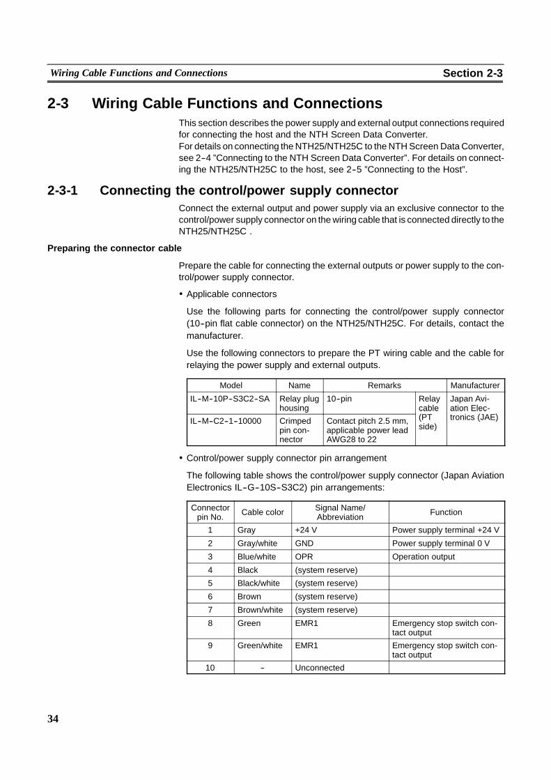
! Control/power supply connector pin arrangement
The following table shows the control/power supply connector (Japan AviationElectronics IL--G--10S--S3C2) pin arrangements:
Connectorpin No. Cable color Signal Name/
Abbreviation Function
1 Gray +24 V Power supply terminal +24 V
2 Gray/white GND Power supply terminal 0 V
3 Blue/white OPR Operation output
4 Black (system reserve)
5 Black/white (system reserve)
6 Brown (system reserve)
7 Brown/white (system reserve)
8 Green EMR1 Emergency stop switch con-tact output
9 Green/white EMR1 Emergency stop switch con-tact output
10 -- Unconnected
35
Wiring Cable Functions and Connections Section 2-3
Connecting the control/power supply connector
Insert the control/power supply connector in as far as it will gowith the notch on therelay connector (plug housing) aligned with the NTH25/NTH25C connector (sock-et housing). Do not exert unnecessary force when inserting the connector.
Power supply connection
Caution -- The entire system may stop depending on how the power is switched ON/OFF.Follow the correct procedure when turning the power ON/OFF.
-- Do not perform a dielectric voltage test.
-- If complying with EC directives (low voltage directives), use a power supply withreinforced insulation.
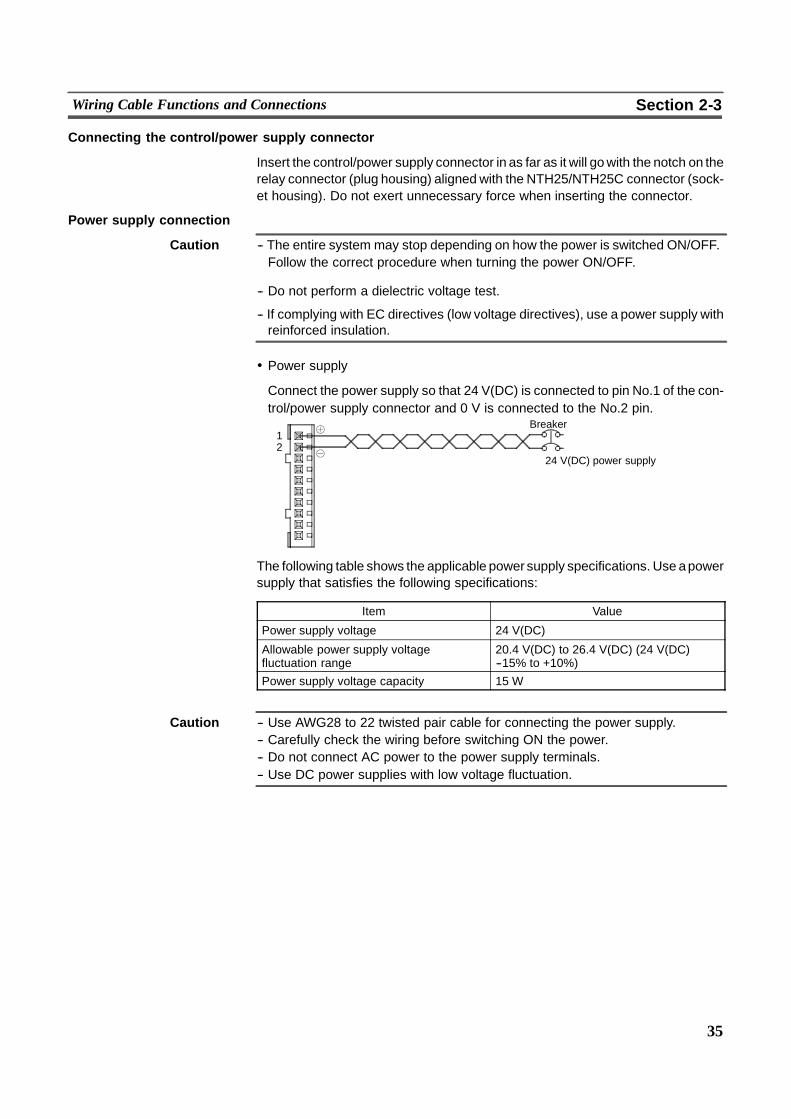
! Power supply
Connect the power supply so that 24 V(DC) is connected to pin No.1 of the con-trol/power supply connector and 0 V is connected to the No.2 pin.
12
Breaker
24 V(DC) power supply
The following table shows the applicable power supply specifications. Use apowersupply that satisfies the following specifications:
Item Value
Power supply voltage 24 V(DC)
Allowable power supply voltagefluctuation range
20.4 V(DC) to 26.4 V(DC) (24 V(DC)--15% to +10%)
Power supply voltage capacity 15 W
Caution -- Use AWG28 to 22 twisted pair cable for connecting the power supply.-- Carefully check the wiring before switching ON the power.-- Do not connect AC power to the power supply terminals.-- Use DC power supplies with low voltage fluctuation.

36
Wiring Cable Functions and Connections Section 2-3
Use of operation output
Pin No.3 (OPR) of the control/power supply connector is an operation switch out-put (Exclusive OR of two operation switches). Operation output can be used byconnecting the required equipment to this pin via the circuit board.With operation output, the state of the two operation switches is exclusive--ORedandoutput only whenone isONand the other isOFF.So it can beused for prevent-ing erroneous operation.The host can also be notified of the state of these operation switches.The action (momentary/alternate) when the switch is pressed is set in ”FunctionKey Settings” on the NTH Screen Data Converter. (See page 265.)Note, however, that operation output and host notification function only when theNTH25/NTH25C is running. These do not function when the NTH25/NTH25C isnot running, for example, while the CHECK menu is displayed or when the pro-gramming console function is being used.
Operationoutput
GND(gray/white)
(blue/white) Inputterminal
COM
12 to 24 V(DC)
Insulation method: PhotocouplerExternal supply power: 12 to 24 V(DC)Max. load current: 50 mA
Internalcircuit
PCinputunit
Caution Operation output is not hard--wired; it is processed in the software. Do not useoperation output in situations where its use may affect human life or cause majordamage, or as emergency output. Implement a failsafe design on the system.
Use of emergency stop output
Pins No.8 (EMR1) and No.9 (EMR2) of the control/power supply connector areemergency stop switch outputs. Emergency stop output can be used by connect-ing the required equipment to these pins via the circuit board.Once the emergency switch is pressed, it stays pressed (its output stays ON). So,the output can be used for an emergency stop. To cancel the switch (turn outputOFF), turn the emergency stop (push--lock) switch on the NTH25/NTH25C to theright (clockwise).
Push--lockoutput
(green/white)
(green)
LoadPush--lockoutputPush--
lockswitch 12 to 24 V(DC)
Type: Normally closed conditionExternal supply power: 5 to 24 V(DC)Max. load current: 1 mA to 1 A
Reference Do not connect a load that exceeds 24 V(DC) 1A.
37
Wiring Cable Functions and Connections Section 2-3
2-3-2 Connecting the 9--pin D--SUB ConnectorConnect the tool connector cable or PC connector cable to the 9--pin D--SUB con-nector (female) of the wiring cable that is directly connected to theNTH25/NTH25C.Connect the tool connector cable to the personal computer (onwhich NTHScreenData Converter is running), and connect the PC connector cable to the host (PC).For details on personal computer (on which NTH Screen Data Converter is run-ning) connections, see 2--4 ”Connecting to the NTH Screen Data Converter”. Fordetails on connecting to the host, see 2--5 ”Connecting to the Host”.
Pin arrangement of 9--pin D--SUB connector
The pin arrangement of the 9--pin D--SUB connector (female) is as follows:
Connector pinNo. Abbreviation Signal Name Signal Direction
(PT$ host/computer)
2 SD Send data %
3 RD Receive data "
4 RS Request send %
5 CS Clear to send "
9 SG Grounding for signal --
Connector hood FG Functional grounding --
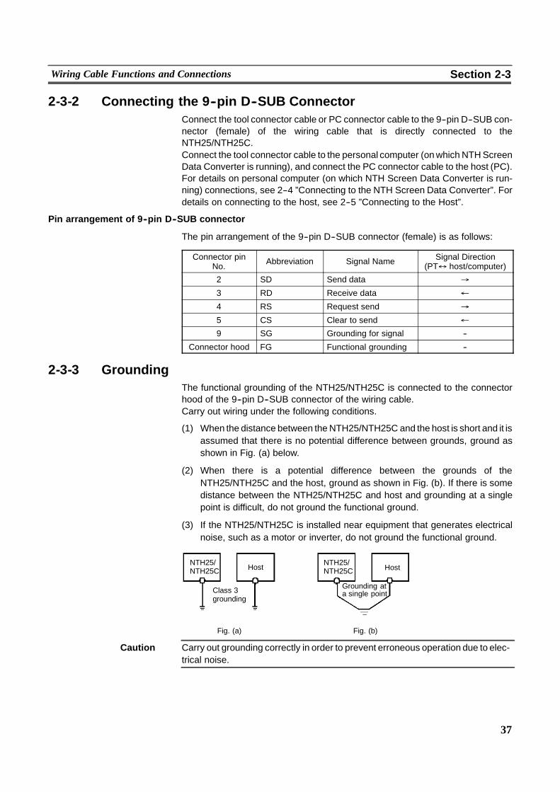
2-3-3 GroundingThe functional grounding of the NTH25/NTH25C is connected to the connectorhood of the 9--pin D--SUB connector of the wiring cable.Carry out wiring under the following conditions.
(1) When the distance between theNTH25/NTH25C and the host is short and it isassumed that there is no potential difference between grounds, ground asshown in Fig. (a) below.
(2) When there is a potential difference between the grounds of theNTH25/NTH25C and the host, ground as shown in Fig. (b). If there is somedistance between the NTH25/NTH25C and host and grounding at a singlepoint is difficult, do not ground the functional ground.
(3) If the NTH25/NTH25C is installed near equipment that generates electricalnoise, such as a motor or inverter, do not ground the functional ground.
Fig. (a) Fig. (b)
Class 3grounding
a single pointGrounding at
NTH25/NTH25C Host
NTH25/NTH25C Host
Caution Carry out grounding correctly in order to prevent erroneous operation due to elec-trical noise.
38
Connecting to the NTH Screen Data Converter Section 2-4
2-4 Connecting to the NTH Screen Data ConverterThe NTH Screen Data Converter is for making settings unique to theNTH25/NTH25C, and converting screen data created on the Support Tool forsending to the NTH25/NTH25C.To send screen data to the NTH25/NTH25C, connect the NTH25/NTH25C to thepersonal computer on which NTH Screen Data Converter is running via the toolconnector cable.
Do not connect the 9--pin connector of the NTH25/NTH25C directly to theRS--232C port on the personal computer.
Reference - Screen data cannot be sent directly from the Support Tool to theNTH25/NTH25C.
- The screen data for the NTH25/NTH25C must be created as the screen data forthe NT31/NT31C on the Support Tool (Save it as ammi format screen data file).The NTH Screen Data Converter reads the saved mmi format screen data, ap-pends the screen data with settings specific to the NTH25/NTH25C, convertsthis data to screen data exclusively for use on the NTH25/NTH25C and sendsthe converted data to the NTH25/NTH25C.
- The NTH Screen Data Converter does not have a function for receiving (upload-ing) data stored on theNTH25/NTH25C. To back up screendata, besure to savescreen data created using the NT--series Support Tool.

39
Connecting to the NTH Screen Data Converter Section 2-4
2-4-1 Connection MethodConnect the RS--232C connector on the NTH25/NTH25C’s wiring cable to theconnector on the tool connector cable connected to the personal computer.The following tool connector cables can be used:
Model CV500--CN228 (cable length 2 m, made by OMRON)(D--SUB 9--pin male$ D--SUB 25--pin male for NEC PC--9800 series exclud-ing PC98--NX)
Model XW2Z--S001 (conversion cable, made by OMRON)(D--SUB 25--pin female $ half--pitch 14--pin male for NEC notebook typePC--9800 series excluding PC98--NX)A separate connector cable CV500--CN228 is needed for using this cable.
Model XW2Z--S002 (cable length 2 m, made by OMRON)(D--SUB 9--pin male$ D--SUB 9--pin female, for PC/AT compatible personalcomputers
PT
Computer
9--pinconnector
Tool connectorcable
Control/powersupply connector
Wiring cable (5 m)Support ToolNTH Screen Data Converter
! Communications conditions
The communications conditions are automatically set when the NTH ScreenData Converter is started up. (You need to specify only the communicationsport.)
40
Connecting to the Host Section 2-5
2-5 Connecting to the HostThe following describes the method for connecting between the NTH25/NTH25Cand the host.Connect the PC connector cable to the RS--232C connector (D--SUB 9--pin con-nector) on the NTH25/NTH25C’s wiring cable. Then connect the PC connectorcable to the RS--232C port on the host.The following PC connector cables can be used:
Model XW2Z--200T (9--pin and host side 9--pin connection, 2 m)Model XW2Z--500T (9--pin and host side 9--pin connection, 5 m)Model XW2Z--200S (9--pin and host side 25--pin connection, 2 m)Model XW2Z--500S (9--pin and host side 25--pin connection, 5 m)
Fasten the above cable connectors and NTH25/NTH25C RS--232C connectorswith screws using the mounting fixture (XM2Z--0001, sold separately).The tensile load of thewiring cable is 30N. Donot apply a load exceeding this limit.
2-5-1 Host Types and SettingsThe following describes the types of host that can be connected to a PT and thesettings to be made at the host.
When using the host link
! Compatible host units
Some models and series of OMRON PCs have the host link function built in. Inaddition, some C200HX/HG/HE (--Z) have an integral CPU that can be con-nected by the host link by installing a communications board.Check the model and series of the PC against the type of installed host link unitbefore making the connections.The following table shows the host units that can be connected to theNTH25/NTH25C by the host link.
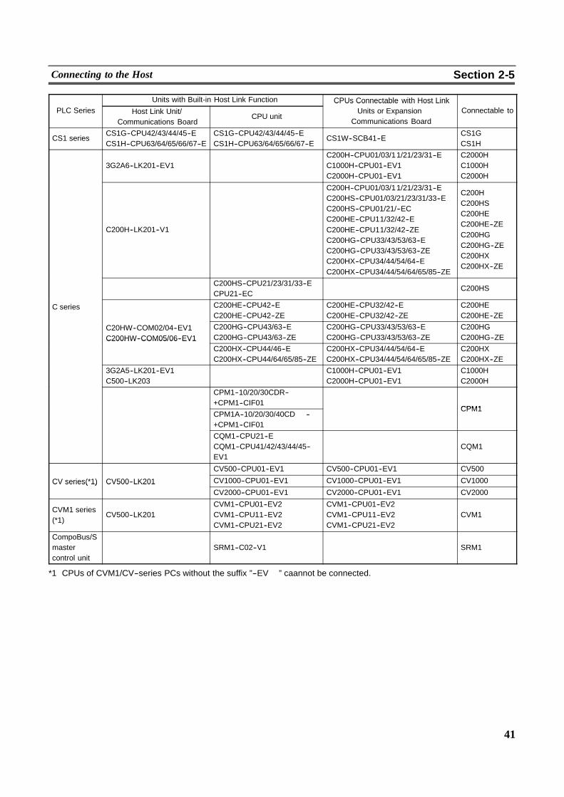
41
Connecting to the Host Section 2-5
Units with Built-in Host Link Function CPUs Connectable with Host LinkPLC Series Host Link Unit/
Communications BoardCPU unit
CPUs Connectable with Host LinkUnits or Expansion
Communications BoardConnectable to
CS1 seriesCS1G--CPU42/43/44/45--ECS1H--CPU63/64/65/66/67--E
CS1G--CPU42/43/44/45--ECS1H--CPU63/64/65/66/67--E
CS1W--SCB41--ECS1GCS1H
3G2A6--LK201--EV1C200H--CPU01/03/11/21/23/31--EC1000H--CPU01--EV1C2000H--CPU01--EV1
C2000HC1000HC2000H
C200H--LK201--V1
C200H--CPU01/03/11/21/23/31--EC200HS--CPU01/03/21/23/31/33--EC200HS--CPU01/21/--ECC200HE--CPU11/32/42--EC200HE--CPU11/32/42--ZEC200HG--CPU33/43/53/63--EC200HG--CPU33/43/53/63--ZEC200HX--CPU34/44/54/64--EC200HX--CPU34/44/54/64/65/85--ZE
C200HC200HSC200HEC200HE--ZEC200HGC200HG--ZEC200HXC200HX--ZE
C200HS--CPU21/23/31/33--ECPU21--EC
C200HS
C series C200HE--CPU42--EC200HE--CPU42--ZE
C200HE--CPU32/42--EC200HE--CPU32/42--ZE
C200HEC200HE--ZE
C20HW--COM02/04--EV1C200HW--COM05/06--EV1
C200HG--CPU43/63--EC200HG--CPU43/63--ZE
C200HG--CPU33/43/53/63--EC200HG--CPU33/43/53/63--ZE
C200HGC200HG--ZEC200HW COM05/06 EV1
C200HX--CPU44/46--EC200HX--CPU44/64/65/85--ZE
C200HX--CPU34/44/54/64--EC200HX--CPU34/44/54/64/65/85--ZE
C200HXC200HX--ZE
3G2A5--LK201--EV1C500--LK203
C1000H--CPU01--EV1C2000H--CPU01--EV1
C1000HC2000H
CPM1--10/20/30CDR-- �+CPM1--CIF01
CPM1CPM1A--10/20/30/40CD � --�+CPM1--CIF01
CPM1
CQM1--CPU21--ECQM1--CPU41/42/43/44/45--EV1
CQM1
CV500--CPU01--EV1 CV500--CPU01--EV1 CV500
CV series(*1) CV500--LK201 CV1000--CPU01--EV1 CV1000--CPU01--EV1 CV1000CV series( 1) CV500 LK201CV2000--CPU01--EV1 CV2000--CPU01--EV1 CV2000
CVM1 series(*1)
CV500--LK201CVM1--CPU01--EV2CVM1--CPU11--EV2CVM1--CPU21--EV2
CVM1--CPU01--EV2CVM1--CPU11--EV2CVM1--CPU21--EV2
CVM1
CompoBus/Smastercontrol unit
SRM1--C02--V1 SRM1
*1 CPUs of CVM1/CV--series PCs without the suffix ”--EV� ” caannot be connected.
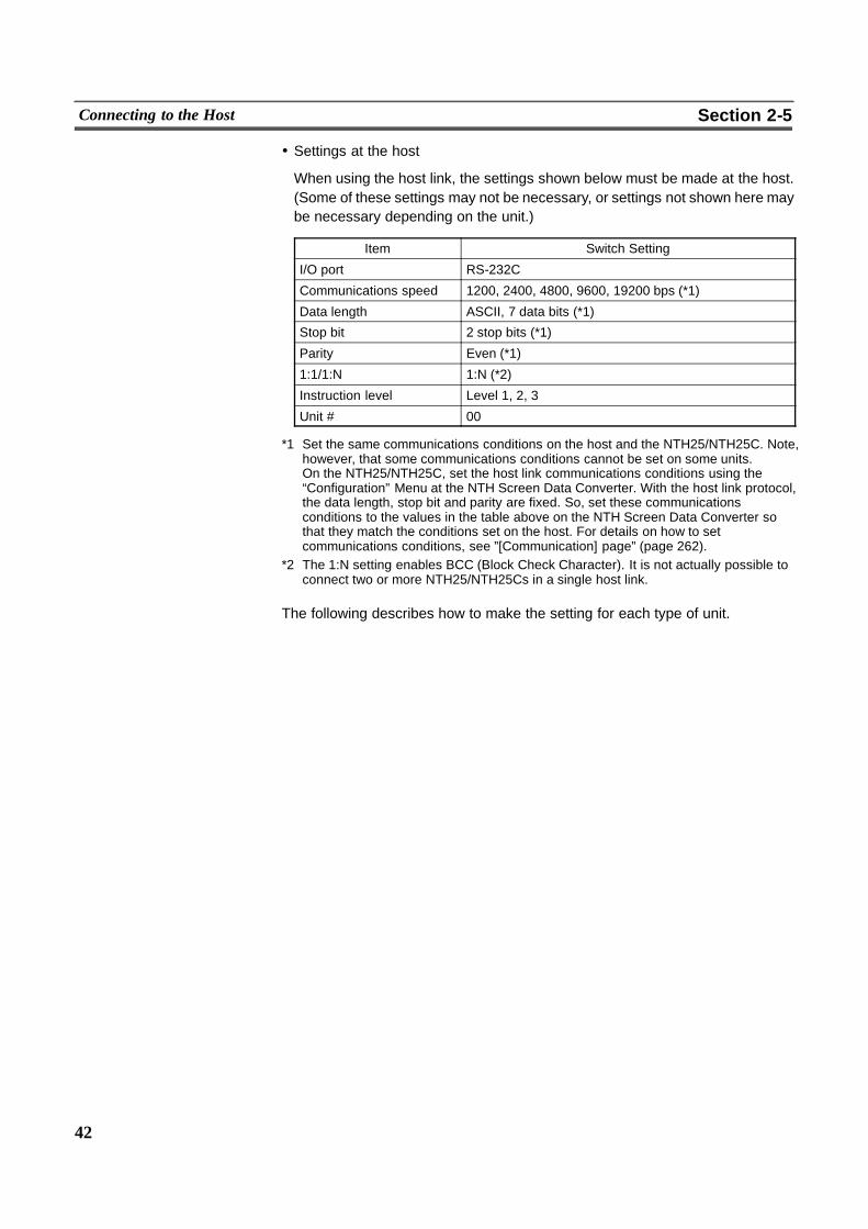
42
Connecting to the Host Section 2-5
! Settings at the host
When using the host link, the settings shown below must be made at the host.(Some of these settings may not be necessary, or settings not shown here maybe necessary depending on the unit.)
Item Switch Setting
I/O port RS-232C
Communications speed 1200, 2400, 4800, 9600, 19200 bps (*1)
Data length ASCII, 7 data bits (*1)
Stop bit 2 stop bits (*1)
Parity Even (*1)
1:1/1:N 1:N (*2)
Instruction level Level 1, 2, 3
Unit # 00
*1 Set the same communications conditions on the host and the NTH25/NTH25C. Note,however, that some communications conditions cannot be set on some units.On the NTH25/NTH25C, set the host link communications conditions using the“Configuration” Menu at the NTH Screen Data Converter. With the host link protocol,the data length, stop bit and parity are fixed. So, set these communicationsconditions to the values in the table above on the NTH Screen Data Converter sothat they match the conditions set on the host. For details on how to setcommunications conditions, see ”[Communication] page” (page 262).
*2 The 1:N setting enables BCC (Block Check Character). It is not actually possible toconnect two or more NTH25/NTH25Cs in a single host link.
The following describes how to make the setting for each type of unit.
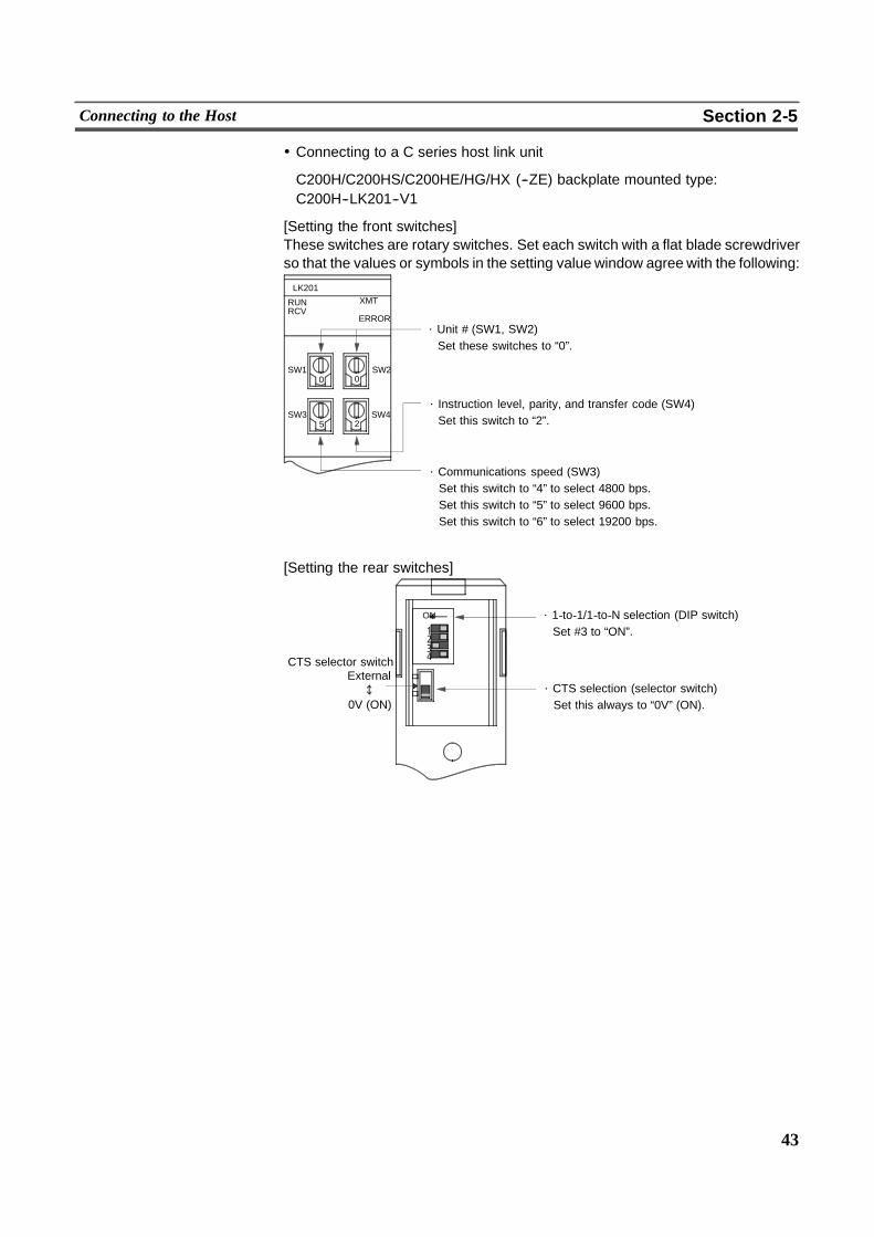
43
Connecting to the Host Section 2-5
! Connecting to a C series host link unit
C200H/C200HS/C200HE/HG/HX (--ZE) backplate mounted type:C200H--LK201--V1
[Setting the front switches]These switches are rotary switches. Set each switch with a flat blade screwdriverso that the values or symbols in the setting value window agree with the following:
LK201
RUNRCV
XMT
ERROR
SW10 0
5 2
⋅ Unit # (SW1, SW2)Set these switches to “0”.
⋅ Instruction level, parity, and transfer code (SW4)Set this switch to “2”.
⋅ Communications speed (SW3)Set this switch to “4” to select 4800 bps.Set this switch to “5” to select 9600 bps.Set this switch to “6” to select 19200 bps.
SW3
SW2
SW4
[Setting the rear switches]
ON
1
CTS selector switchExternal
0V (ON)
⋅ 1-to-1/1-to-N selection (DIP switch)Set #3 to “ON”.
⋅ CTS selection (selector switch)Set this always to “0V” (ON).
234
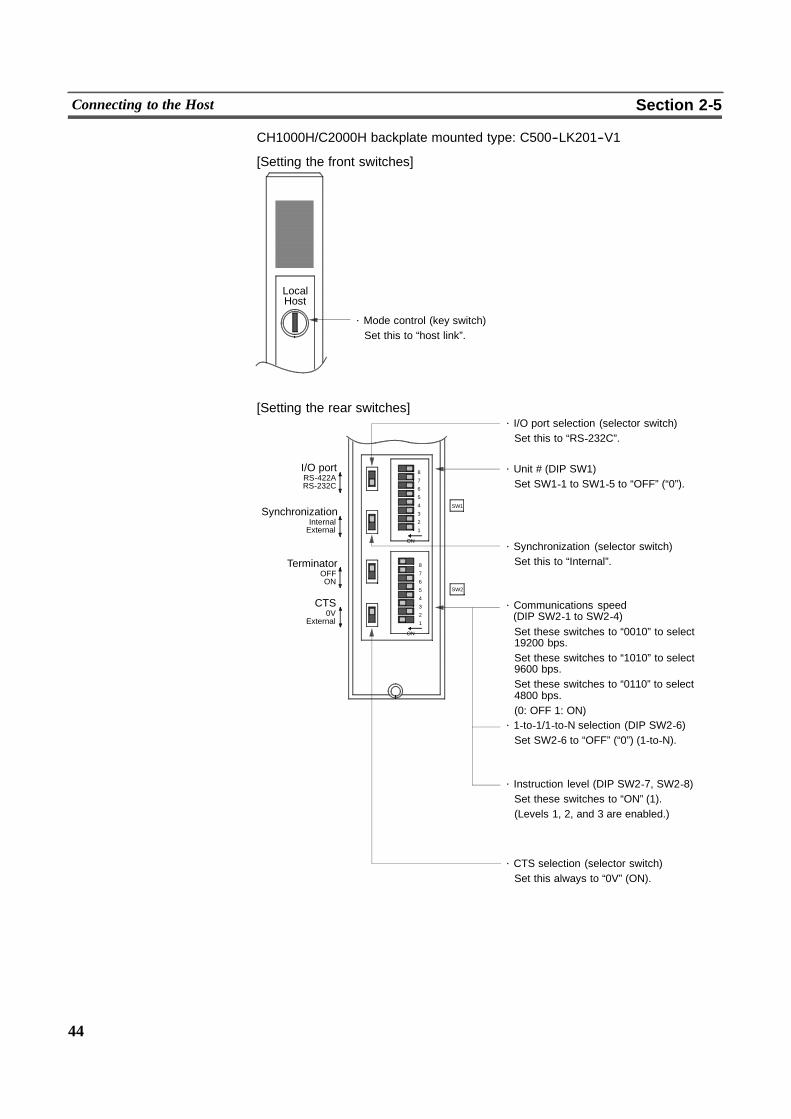
44
Connecting to the Host Section 2-5
CH1000H/C2000H backplate mounted type: C500--LK201--V1
[Setting the front switches]
⋅ Mode control (key switch)Set this to “host link”.
LocalHost
[Setting the rear switches]
ON
ON
SW1
SW2
1
2
3
4
5
6
7
8I/O portRS-422ARS-232C
SynchronizationInternalExternal
TerminatorOFFON
CTS0V
External
⋅ I/O port selection (selector switch)Set this to “RS-232C”.
⋅ Unit # (DIP SW1)Set SW1-1 to SW1-5 to “OFF” (“0”).
⋅ Synchronization (selector switch)Set this to “Internal”.
⋅ Communications speed(DIP SW2-1 to SW2-4)Set these switches to “0010” to select19200 bps.Set these switches to “1010” to select9600 bps.Set these switches to “0110” to select4800 bps.(0: OFF 1: ON)
⋅ 1-to-1/1-to-N selection (DIP SW2-6)Set SW2-6 to “OFF” (“0”) (1-to-N).
⋅ Instruction level (DIP SW2-7, SW2-8)Set these switches to “ON” (1).(Levels 1, 2, and 3 are enabled.)
⋅ CTS selection (selector switch)Set this always to “0V” (ON).
1
2
3
4
5
6
7
8
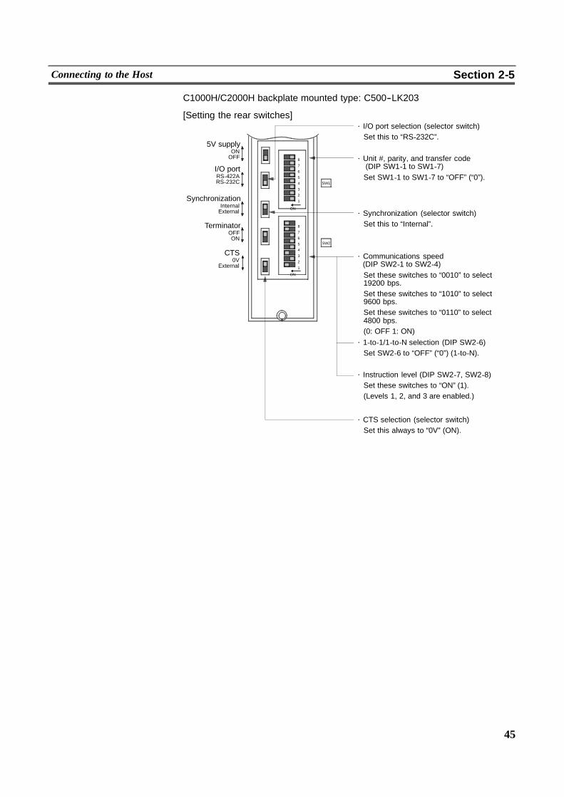
45
Connecting to the Host Section 2-5
C1000H/C2000H backplate mounted type: C500--LK203
[Setting the rear switches]
ON
ON
��
SW1
SW2
I/O portRS-422ARS-232C
SynchronizationInternalExternal
TerminatorOFFON
CTS0V
External
⋅ I/O port selection (selector switch)Set this to “RS-232C”.
⋅ Synchronization (selector switch)Set this to “Internal”.
⋅ Communications speed(DIP SW2-1 to SW2-4)Set these switches to “0010” to select19200 bps.Set these switches to “1010” to select9600 bps.Set these switches to “0110” to select4800 bps.(0: OFF 1: ON)
⋅ 1-to-1/1-to-N selection (DIP SW2-6)Set SW2-6 to “OFF” (“0”) (1-to-N).
⋅ Instruction level (DIP SW2-7, SW2-8)Set these switches to “ON” (1).(Levels 1, 2, and 3 are enabled.)
5V supplyONOFF ⋅ Unit #, parity, and transfer code
(DIP SW1-1 to SW1-7)Set SW1-1 to SW1-7 to “OFF” (“0”).
⋅ CTS selection (selector switch)Set this always to “0V” (ON).
1
2
3
4
5
6
7
8
1
2
3
4
5
6
7
8
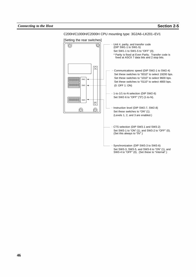
46
Connecting to the Host Section 2-5
C200H/C1000H/C2000H CPU mounting type: 3G2A6--LK201--EV1
[Setting the rear switches]
SW1
SW2
SW3
⋅ Unit #, parity, and transfer code(DIP SW1-1 to SW1-5)Set SW1-1 to SW1-5 to “OFF” (0).* Parity is fixed at Even Parity. Transfer code isfixed at ASCII 7 data bits and 2 stop bits.
⋅ Communications speed (DIP SW2-1 to SW2-4)Set these switches to “0010” to select 19200 bps.Set these switches to “1010” to select 9600 bps.Set these switches to “0110” to select 4800 bps.(0: OFF 1: ON)
⋅ 1-to-1/1-to-N selection (DIP SW2-6)Set SW2-6 to “OFF” (“0”) (1-to-N).
⋅ Instruction level (DIP SW2-7, SW2-8)Set these switches to “ON” (1).(Levels 1, 2, and 3 are enabled.)
⋅ CTS selection (DIP SW3-1 and SW3-2)Set SW3-1 to “ON” (1), and SW3-2 to “OFF” (0).(Set this always to “0V”.)
⋅ Synchronization (DIP SW3-3 to SW3-6)Set SW3-3, SW3-5, and SW3-6 to “ON” (1), andSW3-4 to “OFF” (0). (Set these to “Internal”.)
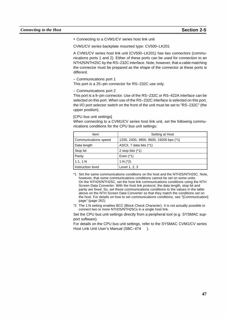
47
Connecting to the Host Section 2-5
! Connecting to a CVM1/CV series host link unit
CVM1/CV series backplate mounted type: CV500--LK201
A CVM1/CV series host link unit (CV500--LK201) has two connectors (commu-nications ports 1 and 2). Either of these ports can be used for connection to anNTH25/NTH25C by the RS--232C interface. Note, however, that a cablematchingthe connector must be prepared as the shape of the connector at these ports isdifferent.
-- Communications port 1This port is a 25--pin connector for RS--232C use only.
-- Communications port 2This port is a 9--pin connector. Use of the RS--232C or RS--422A interface can beselected on this port. When use of the RS--232C interface is selected on this port,the I/O port selector switch on the front of the unit must be set to ”RS--232C” (theupper position).
[CPU bus unit settings]When connecting to a CVM1/CV series host link unit, set the following commu-nications conditions for the CPU bus unit settings:
Item Setting at Host
Communications speed 1200, 2400, 4800, 9600, 19200 bps (*1)
Data length ASCII, 7 data bits (*1)
Stop bit 2 stop bits (*1)
Parity Even (*1)
1:1, 1:N 1:N (*2)
Instruction level Level 1, 2, 3
*1 Set the same communications conditions on the host and the NTH25/NTH25C. Note,however, that some communications conditions cannot be set on some units.On the NTH25/NTH25C, set the host link communications conditions using the NTHScreen Data Converter. With the host link protocol, the data length, stop bit andparity are fixed. So, set these communications conditions to the values in the tableabove on the NTH Screen Data Converter so that they match the conditions set onthe host. For details on how to set communications conditions, see ”[Communication]page” (page 262).
*2 The 1:N setting enables BCC (Block Check Character). It is not actually possible toconnect two or more NTH25/NTH25Cs in a single host link.
Set the CPU bus unit settings directly from a peripheral tool (e.g. SYSMAC sup-port software).For details on the CPU bus unit settings, refer to the SYSMAC CVM1/CV seriesHost Link Unit User’s Manual (SBC--474 � ).
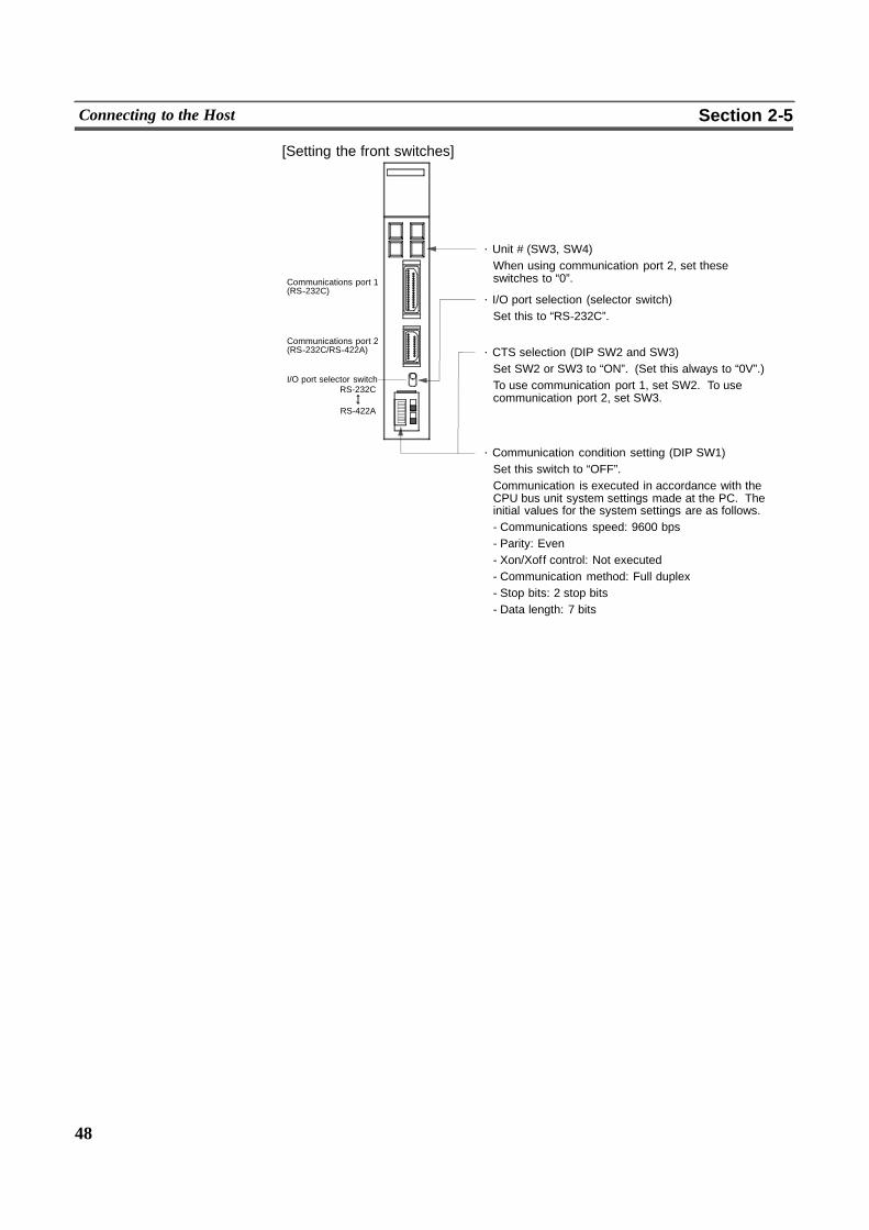
48
Connecting to the Host Section 2-5
[Setting the front switches]
RS-232C
Communications port 1(RS-232C)
Communications port 2(RS-232C/RS-422A)
I/O port selector switch
RS-422A
⋅ Unit # (SW3, SW4)When using communication port 2, set theseswitches to “0”.
⋅ Communication condition setting (DIP SW1)Set this switch to “OFF”.Communication is executed in accordance with theCPU bus unit system settings made at the PC. Theinitial values for the system settings are as follows.- Communications speed: 9600 bps- Parity: Even- Xon/Xoff control: Not executed- Communication method: Full duplex- Stop bits: 2 stop bits- Data length: 7 bits
⋅ I/O port selection (selector switch)Set this to “RS-232C”.
⋅ CTS selection (DIP SW2 and SW3)Set SW2 or SW3 to “ON”. (Set this always to “0V”.)To use communication port 1, set SW2. To usecommunication port 2, set SW3.
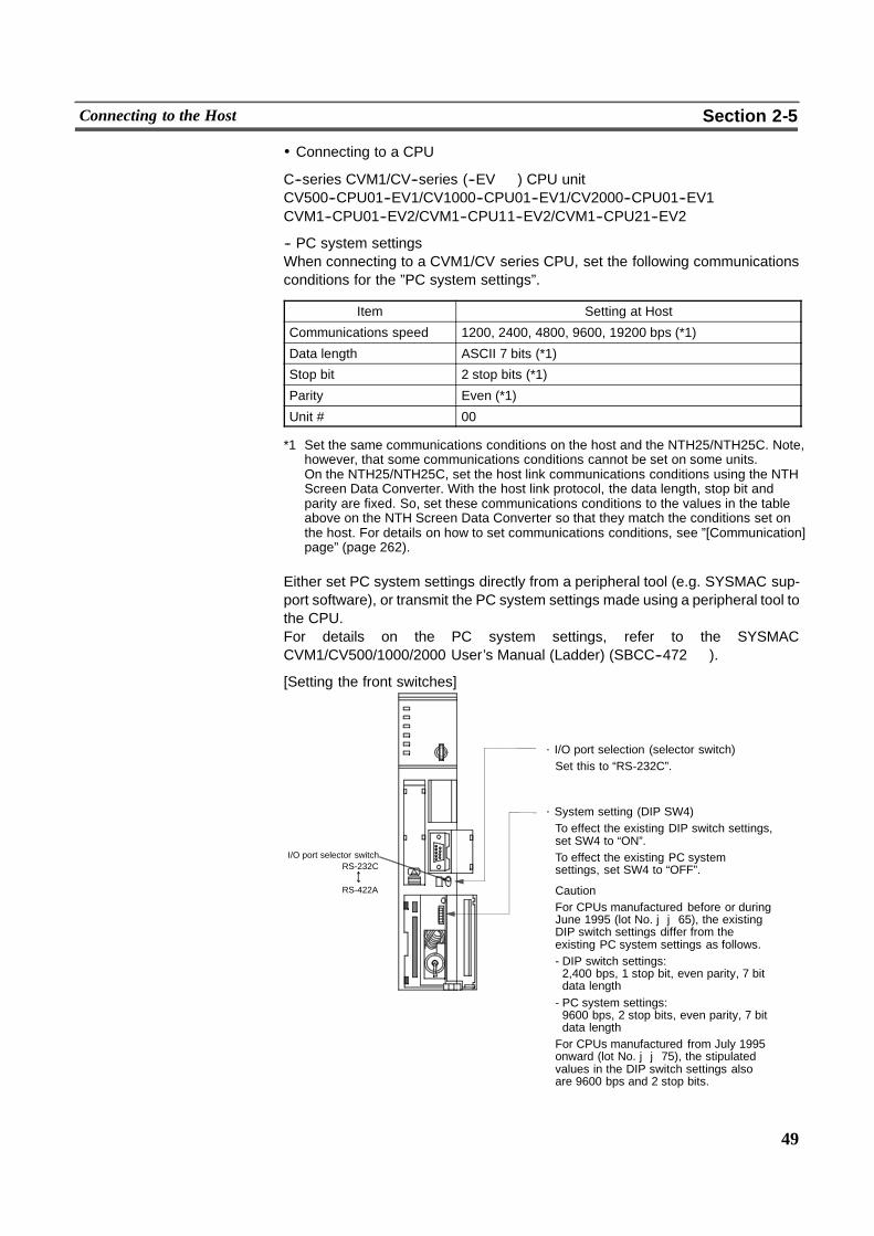
49
Connecting to the Host Section 2-5
! Connecting to a CPU
C--series CVM1/CV--series (--EV � ) CPU unitCV500--CPU01--EV1/CV1000--CPU01--EV1/CV2000--CPU01--EV1CVM1--CPU01--EV2/CVM1--CPU11--EV2/CVM1--CPU21--EV2
-- PC system settingsWhen connecting to a CVM1/CV series CPU, set the following communicationsconditions for the ”PC system settings”.
Item Setting at Host
Communications speed 1200, 2400, 4800, 9600, 19200 bps (*1)
Data length ASCII 7 bits (*1)
Stop bit 2 stop bits (*1)
Parity Even (*1)
Unit # 00
*1 Set the same communications conditions on the host and the NTH25/NTH25C. Note,however, that some communications conditions cannot be set on some units.On the NTH25/NTH25C, set the host link communications conditions using the NTHScreen Data Converter. With the host link protocol, the data length, stop bit andparity are fixed. So, set these communications conditions to the values in the tableabove on the NTH Screen Data Converter so that they match the conditions set onthe host. For details on how to set communications conditions, see ”[Communication]page” (page 262).
Either set PC system settings directly from a peripheral tool (e.g. SYSMAC sup-port software), or transmit the PC system settings made using a peripheral tool tothe CPU.For details on the PC system settings, refer to the SYSMACCVM1/CV500/1000/2000 User’s Manual (Ladder) (SBCC--472 � ).
[Setting the front switches]
RS-232CI/O port selector switch
RS-422A
⋅ I/O port selection (selector switch)Set this to “RS-232C”.
⋅ System setting (DIP SW4)To effect the existing DIP switch settings,set SW4 to “ON”.To effect the existing PC systemsettings, set SW4 to “OFF”.
CautionFor CPUs manufactured before or duringJune 1995 (lot No. jj65), the existingDIP switch settings differ from theexisting PC system settings as follows.- DIP switch settings:2,400 bps, 1 stop bit, even parity, 7 bitdata length- PC system settings:9600 bps, 2 stop bits, even parity, 7 bitdata lengthFor CPUs manufactured from July 1995onward (lot No. jj75), the stipulatedvalues in the DIP switch settings alsoare 9600 bps and 2 stop bits.

50
Connecting to the Host Section 2-5
C--series C200HS, C200HX/HG/HE (--ZE), CPM1, CQM1 CPUs, SRM1
Connect to theRS--232C port with the built--in CPU unit, or theRS--232C port (portA or B) of the communications board. Note that the connection to aCPM1must bemade via an RS--232C adapter (CPM1--CIF01).
Reference Connection to the peripheral port of the CPU unit is not possible.
-- PC system setting area settingsWhen connecting to a C200HS, C200HX/HG/HE (--ZE), CPM1, or CQM1 CPU, orSRM1, set the communications conditions for the PC system setting area as fol-lows:
Item Setting at Host
Communications mode Host link mode
Communications speed 1200, 2400, 4800, 9600, 19200 bps (*1)
Data length ASCII 7 bits (*1)
Stop bit 2 stop bits (*1)
Parity Even (*1)
Unit # 00
*1 Set the same communications conditions on the host and the NTH25/NTH25C. Note,however, that some communications conditions cannot be set on some units.On the NTH25/NTH25C, set the host link communications conditions using the NTHScreen Data Converter. With the host link protocol, the data length, stop bit andparity are fixed. So, set these communications conditions to the values in the tableabove on the NTH Screen Data Converter so that they match the conditions set onthe host. For details on how to set communications conditions, see ”[Communication]page” (page 262).
Set the PC system setting area settings directly from a peripheral tool (e.g. SYS-MAC support software).For details on operations on the PC system setting area, refer to themanual for thePC in use.
The following shows the PC system setting area word numbers and settings to bemade depending on the unit and port to which the connection is made.
When using the built--in RS--232C port of C200HS, C200HX/HG/HE (--ZE),CQM1, SRM1
Word Number Writing Value Settings
DM6645 0001 Host link mode, CTS control OFFCommunications conditions are set by thecontents of DM.
DM6646 0302 Data length 7 bits, 2 stop bits, even parity,communications speed 4800 bps
0303 Data length 7 bits, 2 stop bits, even parity,communications speed: 9600 bps
0304 Data length 7 bits, 2 stop bits, even parity,communications speed: 19200 bps
DM6648 0000 Unit # 00
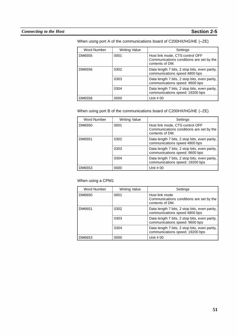
51
Connecting to the Host Section 2-5
When using port A of the communications board of C200HX/HG/HE (--ZE)
Word Number Writing Value Settings
DM6555 0001 Host link mode, CTS control OFFCommunications conditions are set by thecontents of DM.
DM6556 0302 Data length 7 bits, 2 stop bits, even parity,communications speed 4800 bps
0303 Data length 7 bits, 2 stop bits, even parity,communications speed: 9600 bps
0304 Data length 7 bits, 2 stop bits, even parity,communications speed: 19200 bps
DM6558 0000 Unit # 00
When using port B of the communications board of C200HX/HG/HE (--ZE)
Word Number Writing Value Settings
DM6550 0001 Host link mode, CTS control OFFCommunications conditions are set by thecontents of DM.
DM6551 0302 Data length 7 bits, 2 stop bits, even parity,communications speed 4800 bps
0303 Data length 7 bits, 2 stop bits, even parity,communications speed: 9600 bps
0304 Data length 7 bits, 2 stop bits, even parity,communications speed: 19200 bps
DM6553 0000 Unit # 00
When using a CPM1
Word Number Writing Value Settings
DM6650 0001 Host link modeCommunications conditions are set by thecontents of DM.
DM6651 0302 Data length 7 bits, 2 stop bits, even parity,communications speed 4800 bps
0303 Data length 7 bits, 2 stop bits, even parity,communications speed: 9600 bps
0304 Data length 7 bits, 2 stop bits, even parity,communications speed: 19200 bps
DM6653 0000 Unit # 00
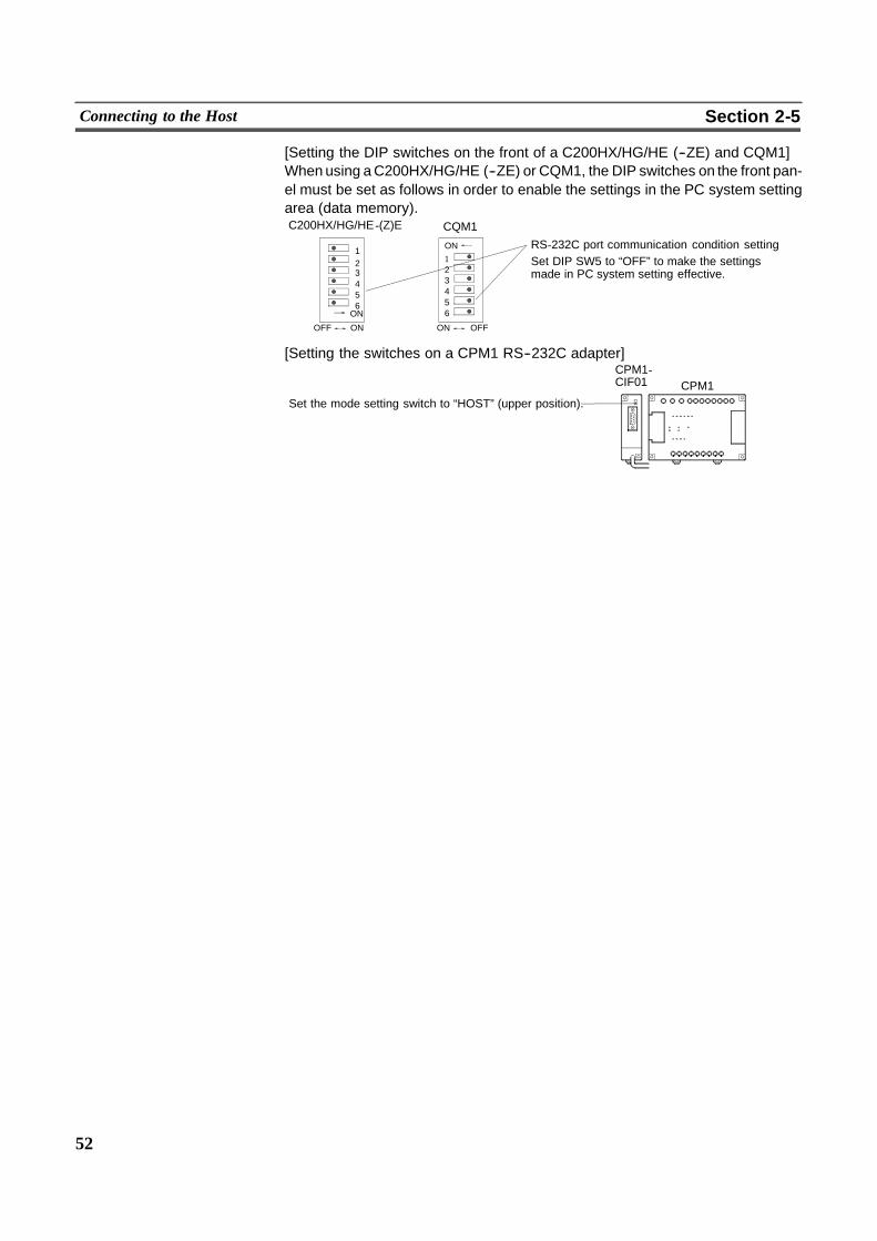
52
Connecting to the Host Section 2-5
[Setting the DIP switches on the front of a C200HX/HG/HE (--ZE) and CQM1]Whenusing aC200HX/HG/HE (--ZE) or CQM1, the DIP switches on the front pan-el must be set as follows in order to enable the settings in the PC system settingarea (data memory).
OFFONONOFF
123456ON
ON
C200HX/HG/HE -(Z)E CQM1
RS-232C port communication condition settingSet DIP SW5 to “OFF” to make the settingsmade in PC system setting effective.
123456
[Setting the switches on a CPM1 RS--232C adapter]
CPM1Set the mode setting switch to “HOST” (upper position).
CPM1-CIF01
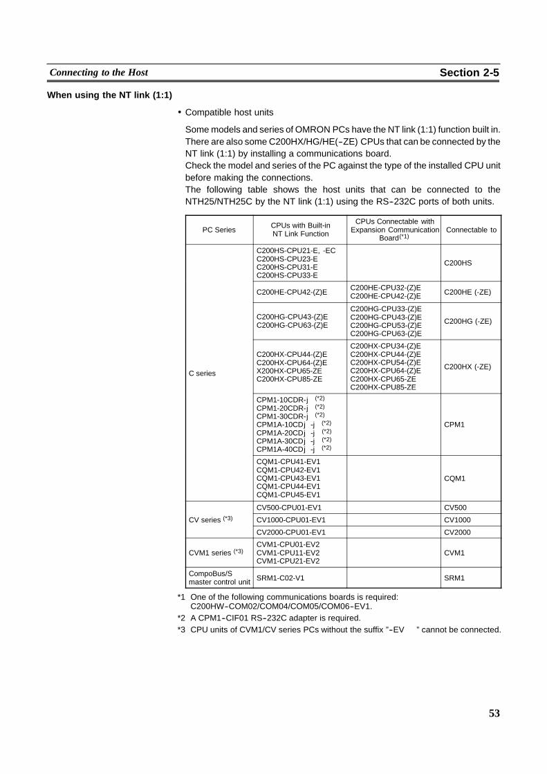
53
Connecting to the Host Section 2-5
When using the NT link (1:1)
! Compatible host units
Somemodels and series of OMRON PCs have the NT link (1:1) function built in.There are also some C200HX/HG/HE(--ZE) CPUs that can be connected by theNT link (1:1) by installing a communications board.Check the model and series of the PC against the type of the installed CPU unitbefore making the connections.The following table shows the host units that can be connected to theNTH25/NTH25C by the NT link (1:1) using the RS--232C ports of both units.
PC Series CPUs with Built-inNT Link Function
CPUs Connectable withExpansion Communication
Board(*1)Connectable to
C200HS-CPU21-E, -ECC200HS-CPU23-EC200HS-CPU31-EC200HS-CPU33-E
C200HS
C200HE-CPU42-(Z)E C200HE-CPU32-(Z)EC200HE-CPU42-(Z)E C200HE (-ZE)
C200HG-CPU43-(Z)EC200HG-CPU63-(Z)E
C200HG-CPU33-(Z)EC200HG-CPU43-(Z)EC200HG-CPU53-(Z)EC200HG-CPU63-(Z)E
C200HG (-ZE)
C series
C200HX-CPU44-(Z)EC200HX-CPU64-(Z)EX200HX-CPU65-ZEC200HX-CPU85-ZE
C200HX-CPU34-(Z)EC200HX-CPU44-(Z)EC200HX-CPU54-(Z)EC200HX-CPU64-(Z)EC200HX-CPU65-ZEC200HX-CPU85-ZE
C200HX (-ZE)
CPM1-10CDR-j (*2)
CPM1-20CDR-j (*2)
CPM1-30CDR-j (*2)
CPM1A-10CDj-j (*2)
CPM1A-20CDj-j (*2)
CPM1A-30CDj-j (*2)
CPM1A-40CDj-j (*2)
CPM1
CQM1-CPU41-EV1CQM1-CPU42-EV1CQM1-CPU43-EV1CQM1-CPU44-EV1CQM1-CPU45-EV1
CQM1
CV500-CPU01-EV1 CV500
CV series (*3) CV1000-CPU01-EV1 CV1000
CV2000-CPU01-EV1 CV2000
CVM1 series (*3)CVM1-CPU01-EV2CVM1-CPU11-EV2CVM1-CPU21-EV2
CVM1
CompoBus/Smaster control unit SRM1-C02-V1 SRM1
*1 One of the following communications boards is required:C200HW--COM02/COM04/COM05/COM06--EV1.
*2 A CPM1--CIF01 RS--232C adapter is required.*3 CPU units of CVM1/CV series PCs without the suffix ”--EV � ” cannot be connected.

54
Connecting to the Host Section 2-5
! Settings at the host
The following describes the setting methods for each unit.
! Connecting to a C--series C200HS, C200HX/HG/HE(--ZE), CPM1, CQM1,SRM1
[PC system setting area settings]Write the settings to the ”PC system setting area” (data memory) directly from aperipheral tool (e.g. SYSMAC support software) according to the host model andport.
Host Model Word Number Writing Value Setting
Built--in RS-232C port of C200HS,C200HX/HG/HE(-ZE), CQM1, SRM1
DM6645
Port A of C200HX/HG/HE(-ZE) (*1) DM6555 4000 Use NT link(1:1)
Port B of C200HX/HG/HE(-ZE) (*1) DM65504000 (1:1)
CPM1 DM6650
*1 RS--232C port of the communications board
For details on operations on the ”PC system setting area”, refer to the manual forthe PC in use.
[Setting the DIP switches on the front of a C200HX/HG/HE(--ZE)and CQM1]When using a C200HX/HG/HE(--ZE) or CQM1, the DIP switches on the front pan-el must be set as follows to enable the settings in the ”PC system setting area”(data memory).
C200HX/HG/HE-(Z)E CQM1
RS-232C port communication condition settingSet DIP SW5 to “OFF” to make the settingsmade in PC system setting effective.
OFF ON123456
123456ON
OFFON
ON
[Setting the switches on a CPM1 RS--232C adapter]CPM1-CIF01
Set the mode setting switch to “NT” (lower position).
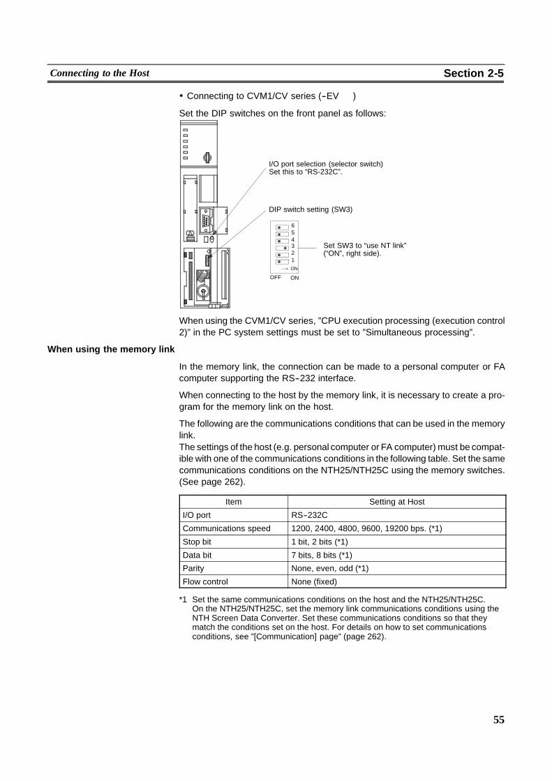
55
Connecting to the Host Section 2-5
! Connecting to CVM1/CV series (--EV � )
Set the DIP switches on the front panel as follows:
OFF ON
123456
ON
I/O port selection (selector switch)Set this to “RS-232C”.
Set SW3 to “use NT link”(“ON”, right side).
DIP switch setting (SW3)
When using the CVM1/CV series, ”CPU execution processing (execution control2)” in the PC system settings must be set to ”Simultaneous processing”.
When using the memory link
In the memory link, the connection can be made to a personal computer or FAcomputer supporting the RS--232 interface.
When connecting to the host by the memory link, it is necessary to create a pro-gram for the memory link on the host.
The following are the communications conditions that can be used in the memorylink.The settings of the host (e.g. personal computer or FA computer) must be compat-ible with one of the communications conditions in the following table. Set the samecommunications conditions on the NTH25/NTH25C using the memory switches.(See page 262).
Item Setting at Host
I/O port RS--232C
Communications speed 1200, 2400, 4800, 9600, 19200 bps. (*1)
Stop bit 1 bit, 2 bits (*1)
Data bit 7 bits, 8 bits (*1)
Parity None, even, odd (*1)
Flow control None (fixed)
*1 Set the same communications conditions on the host and the NTH25/NTH25C.On the NTH25/NTH25C, set the memory link communications conditions using theNTH Screen Data Converter. Set these communications conditions so that theymatch the conditions set on the host. For details on how to set communicationsconditions, see ”[Communication] page” (page 262).
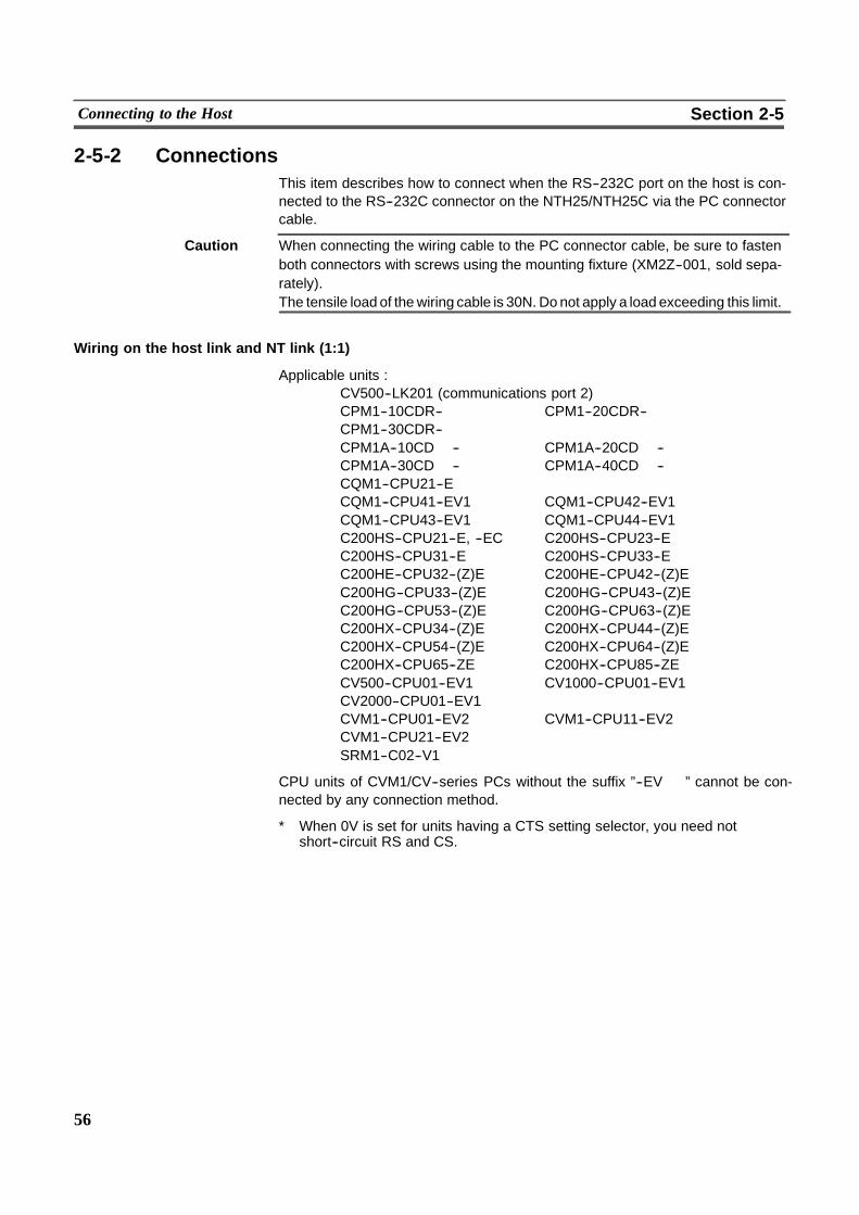
56
Connecting to the Host Section 2-5
2-5-2 ConnectionsThis item describes how to connect when the RS--232C port on the host is con-nected to the RS--232C connector on the NTH25/NTH25C via the PC connectorcable.
Caution When connecting the wiring cable to the PC connector cable, be sure to fastenboth connectors with screws using the mounting fixture (XM2Z--001, sold sepa-rately).The tensile load of thewiring cable is 30N. Donot apply a load exceeding this limit.
Wiring on the host link and NT link (1:1)
Applicable units :CV500--LK201 (communications port 2)CPM1--10CDR--� CPM1--20CDR--�CPM1--30CDR--�CPM1A--10CD� --� CPM1A--20CD� --�CPM1A--30CD� --� CPM1A--40CD� --�CQM1--CPU21--ECQM1--CPU41--EV1 CQM1--CPU42--EV1CQM1--CPU43--EV1 CQM1--CPU44--EV1C200HS--CPU21--E, --EC C200HS--CPU23--EC200HS--CPU31--E C200HS--CPU33--EC200HE--CPU32--(Z)E C200HE--CPU42--(Z)EC200HG--CPU33--(Z)E C200HG--CPU43--(Z)EC200HG--CPU53--(Z)E C200HG--CPU63--(Z)EC200HX--CPU34--(Z)E C200HX--CPU44--(Z)EC200HX--CPU54--(Z)E C200HX--CPU64--(Z)EC200HX--CPU65--ZE C200HX--CPU85--ZECV500--CPU01--EV1 CV1000--CPU01--EV1CV2000--CPU01--EV1CVM1--CPU01--EV2 CVM1--CPU11--EV2CVM1--CPU21--EV2SRM1--C02--V1
CPU units of CVM1/CV--series PCs without the suffix ”--EV � ” cannot be con-nected by any connection method.
* When 0V is set for units having a CTS setting selector, you need notshort--circuit RS and CS.
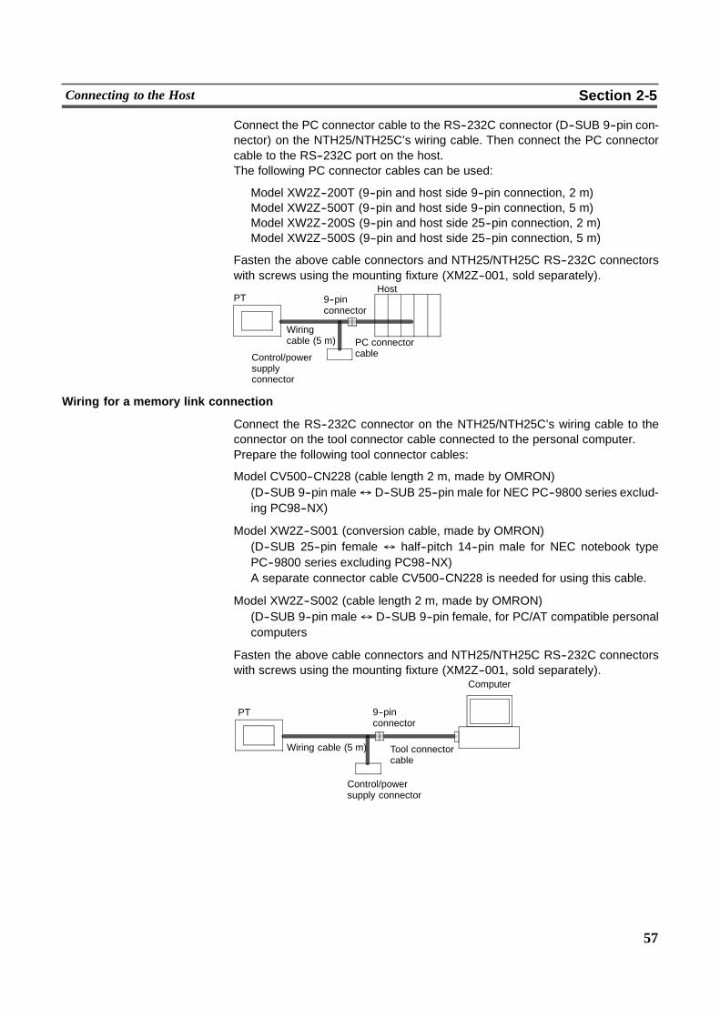
57
Connecting to the Host Section 2-5
Connect the PC connector cable to the RS--232C connector (D--SUB 9--pin con-nector) on the NTH25/NTH25C’s wiring cable. Then connect the PC connectorcable to the RS--232C port on the host.The following PC connector cables can be used:
Model XW2Z--200T (9--pin and host side 9--pin connection, 2 m)Model XW2Z--500T (9--pin and host side 9--pin connection, 5 m)Model XW2Z--200S (9--pin and host side 25--pin connection, 2 m)Model XW2Z--500S (9--pin and host side 25--pin connection, 5 m)
Fasten the above cable connectors and NTH25/NTH25C RS--232C connectorswith screws using the mounting fixture (XM2Z--001, sold separately).
PT 9--pinconnector
Wiringcable (5 m)
Control/powersupplyconnector
Host
PC connectorcable
Wiring for a memory link connection
Connect the RS--232C connector on the NTH25/NTH25C’s wiring cable to theconnector on the tool connector cable connected to the personal computer.Prepare the following tool connector cables:
Model CV500--CN228 (cable length 2 m, made by OMRON)(D--SUB 9--pin male$ D--SUB 25--pin male for NEC PC--9800 series exclud-ing PC98--NX)
Model XW2Z--S001 (conversion cable, made by OMRON)(D--SUB 25--pin female $ half--pitch 14--pin male for NEC notebook typePC--9800 series excluding PC98--NX)A separate connector cable CV500--CN228 is needed for using this cable.
Model XW2Z--S002 (cable length 2 m, made by OMRON)(D--SUB 9--pin male$ D--SUB 9--pin female, for PC/AT compatible personalcomputers
Fasten the above cable connectors and NTH25/NTH25C RS--232C connectorswith screws using the mounting fixture (XM2Z--001, sold separately).
PT
Computer
9--pinconnector
Tool connectorcable
Control/powersupply connector
Wiring cable (5 m)

59
SECTION 3CHECK Menu Operation
This section describes the operation of the CHECK menu, focusing on the procedure to start up the NTH25/NTH25C.This section also describes functions that are convenient when using the NTH25/NTH25C and those that are useful for sys-tem maintenance.
3-1 CHECK Menu Operation Flow 60. . . . . . . . . . . . . . . . . . . . . . . . . . . . . . . . . . . . . . . . . . . . . . . . . .3-2 Starting the NTH25/NTH25C 61. . . . . . . . . . . . . . . . . . . . . . . . . . . . . . . . . . . . . . . . . . . . . . . . . . .
3-2-1 Operation at Startup 61. . . . . . . . . . . . . . . . . . . . . . . . . . . . . . . . . . . . . . . . . . . . . . . . . . . . .3-3 Operation Modes and the CHECK menu 62. . . . . . . . . . . . . . . . . . . . . . . . . . . . . . . . . . . . . . . . . .
3-3-1 Relationships among Modes 62. . . . . . . . . . . . . . . . . . . . . . . . . . . . . . . . . . . . . . . . . . . . . .3-3-2 Operations with the CHECK menu 63. . . . . . . . . . . . . . . . . . . . . . . . . . . . . . . . . . . . . . . . .
3-4 Transmitting the Screen Data 65. . . . . . . . . . . . . . . . . . . . . . . . . . . . . . . . . . . . . . . . . . . . . . . . . . .3-5 Starting Operation 67. . . . . . . . . . . . . . . . . . . . . . . . . . . . . . . . . . . . . . . . . . . . . . . . . . . . . . . . . . . .3-6 Switching the Display Language 69. . . . . . . . . . . . . . . . . . . . . . . . . . . . . . . . . . . . . . . . . . . . . . . .3-7 Adjusting LCD Contrast 70. . . . . . . . . . . . . . . . . . . . . . . . . . . . . . . . . . . . . . . . . . . . . . . . . . . . . . .3-8 Setting the Clock Data 71. . . . . . . . . . . . . . . . . . . . . . . . . . . . . . . . . . . . . . . . . . . . . . . . . . . . . . . .
3-8-1 Setting the Date and Time 72. . . . . . . . . . . . . . . . . . . . . . . . . . . . . . . . . . . . . . . . . . . . . . . .3-9 Checking Screen Data 73. . . . . . . . . . . . . . . . . . . . . . . . . . . . . . . . . . . . . . . . . . . . . . . . . . . . . . . . .3-10 Programming Console Function 74. . . . . . . . . . . . . . . . . . . . . . . . . . . . . . . . . . . . . . . . . . . . . . . . .
3-10-1Usable Systems 74. . . . . . . . . . . . . . . . . . . . . . . . . . . . . . . . . . . . . . . . . . . . . . . . . . . . . . . .3-10-2Connection Method 75. . . . . . . . . . . . . . . . . . . . . . . . . . . . . . . . . . . . . . . . . . . . . . . . . . . . .3-10-3Method of Use 76. . . . . . . . . . . . . . . . . . . . . . . . . . . . . . . . . . . . . . . . . . . . . . . . . . . . . . . . .
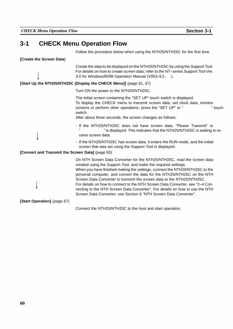
60
CHECK Menu Operation Flow Section 3-1
3-1 CHECK Menu Operation FlowFollow the procedure below when using the NTH25/NTH25C for the first time.
[Create the Screen Data]
Create the data to be displayed on the NTH25/NTH25C by using the Support Tool.For details on how to create screen data, refer to the NT--series Support Tool Ver.3.0 for Windows95/98 Operation Manual (V053--E1--� ).
[Start Up the NTH25/NTH25C (Display the CHECK Menu)] (page 61, 67)
Turn ON the power to the NTH25/NTH25C.
The initial screen containing the ”SET UP” touch switch is displayed.To display the CHECK menu to transmit screen data, set clock data, monitorscreens or perform other operations, press the ”SET UP” or “������ ” touchswitch.After about three seconds, the screen changes as follows:
- If the NTH25/NTH25C does not have screen data, ”Please Transmit” or”����� ” is displayed. This indicates that the NTH25/NTH25C is waiting to re-ceive screen data.
- If the NTH25/NTH25C has screen data, it enters the RUN mode, and the initialscreen that was set using the Support Tool is displayed.
[Convert and Transmit the Screen Data] (page 65)
On NTH Screen Data Converter for the NTH25/NTH25C, read the screen datacreated using the Support Tool, and make the required settings.When you have finished making the settings, connect the NTH25/NTH25C to thepersonal computer, and convert the data for the NTH25/NTH25C on the NTHScreen Data Converter to transmit the screen data to the NTH25/NTH25C.For details on how to connect to the NTH Screen Data Converter, see ”2--4 Con-necting to the NTH Screen Data Converter”. For details on how to use the NTHScreen Data Converter, see Section 6 ”NTH Screen Data Converter”.
[Start Operation] (page 67)
Connect the NTH25/NTH25C to the host and start operation.
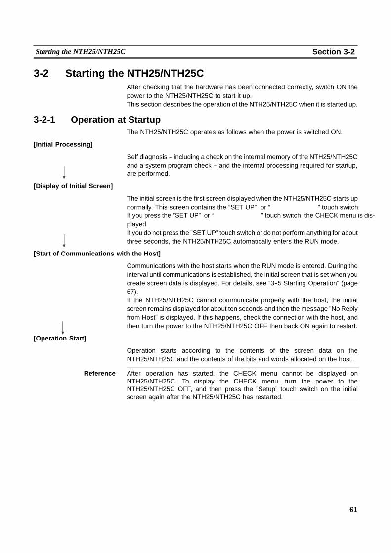
61
Starting the NTH25/NTH25C Section 3-2
3-2 Starting the NTH25/NTH25CAfter checking that the hardware has been connected correctly, switch ON thepower to the NTH25/NTH25C to start it up.This section describes the operation of the NTH25/NTH25C when it is started up.
3-2-1 Operation at StartupThe NTH25/NTH25C operates as follows when the power is switched ON.
[Initial Processing]
Self diagnosis -- including a check on the internal memory of the NTH25/NTH25Cand a system program check -- and the internal processing required for startup,are performed.
[Display of Initial Screen]
The initial screen is the first screen displayed when the NTH25/NTH25C starts upnormally. This screen contains the ”SET UP” or “������ ” touch switch.If you press the ”SET UP” or “������ ” touch switch, the CHECK menu is dis-played.If you do not press the ”SET UP” touch switch or do not perform anything for aboutthree seconds, the NTH25/NTH25C automatically enters the RUN mode.
[Start of Communications with the Host]
Communications with the host starts when the RUN mode is entered. During theinterval until communications is established, the initial screen that is set when youcreate screen data is displayed. For details, see ”3--5 Starting Operation” (page67).If the NTH25/NTH25C cannot communicate properly with the host, the initialscreen remains displayed for about ten seconds and then the message ”NoReplyfrom Host” is displayed. If this happens, check the connection with the host, andthen turn the power to the NTH25/NTH25C OFF then back ON again to restart.
[Operation Start]
Operation starts according to the contents of the screen data on theNTH25/NTH25C and the contents of the bits and words allocated on the host.
Reference After operation has started, the CHECK menu cannot be displayed onNTH25/NTH25C. To display the CHECK menu, turn the power to theNTH25/NTH25C OFF, and then press the ”Setup” touch switch on the initialscreen again after the NTH25/NTH25C has restarted.
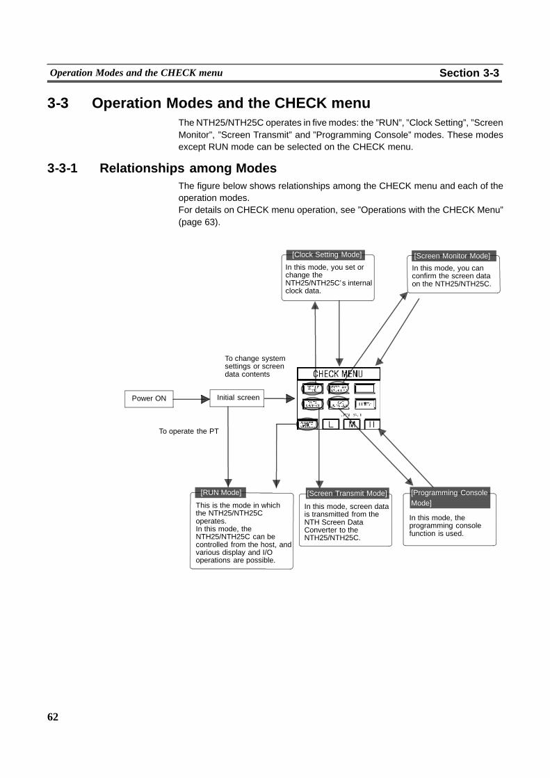
62
Operation Modes and the CHECK menu Section 3-3
3-3 Operation Modes and the CHECK menuThe NTH25/NTH25C operates in five modes: the ”RUN”, ”Clock Setting”, ”ScreenMonitor”, ”Screen Transmit” and ”Programming Console” modes. These modesexcept RUN mode can be selected on the CHECK menu.
3-3-1 Relationships among ModesThe figure below shows relationships among the CHECK menu and each of theoperation modes.For details on CHECK menu operation, see ”Operations with the CHECK Menu”(page 63).
[Clock Setting Mode]
In this mode, you set orchange theNTH25/NTH25C’s internalclock data.
[Screen Monitor Mode]
In this mode, you canconfirm the screen dataon the NTH25/NTH25C.
Power ON
[RUN Mode]
This is the mode in whichthe NTH25/NTH25Coperates.In this mode, theNTH25/NTH25C can becontrolled from the host, andvarious display and I/Ooperations are possible.
[Programming ConsoleMode]
In this mode, theprogramming consolefunction is used.
To change systemsettings or screendata contents
Initial screen
To operate the PT
[Screen Transmit Mode]
In this mode, screen datais transmitted from theNTH Screen DataConverter to theNTH25/NTH25C.
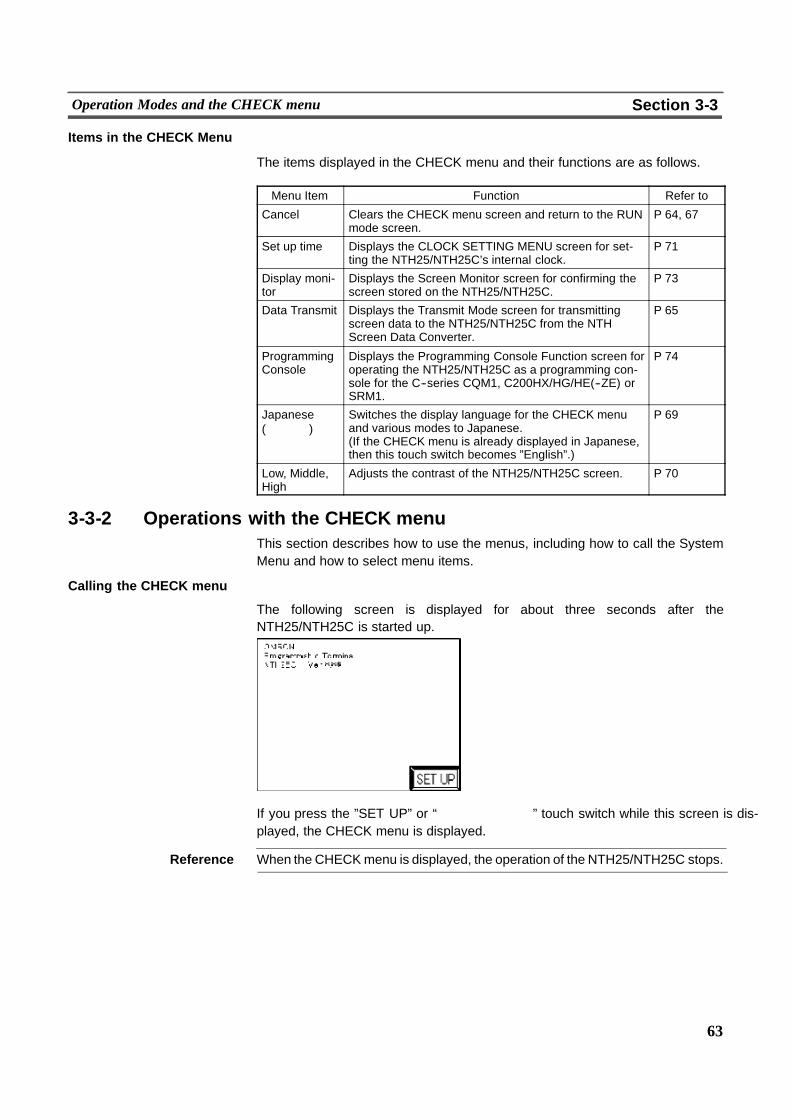
63
Operation Modes and the CHECK menu Section 3-3
Items in the CHECK Menu
The items displayed in the CHECK menu and their functions are as follows.
Menu Item Function Refer to
Cancel Clears the CHECK menu screen and return to the RUNmode screen.
P 64, 67
Set up time Displays the CLOCK SETTING MENU screen for set-ting the NTH25/NTH25C’s internal clock.
P 71
Display moni-tor
Displays the Screen Monitor screen for confirming thescreen stored on the NTH25/NTH25C.
P 73
Data Transmit Displays the Transmit Mode screen for transmittingscreen data to the NTH25/NTH25C from the NTHScreen Data Converter.
P 65
ProgrammingConsole
Displays the Programming Console Function screen foroperating the NTH25/NTH25C as a programming con-sole for the C--series CQM1, C200HX/HG/HE(--ZE) orSRM1.
P 74
Japanese(��� )
Switches the display language for the CHECK menuand various modes to Japanese.(If the CHECK menu is already displayed in Japanese,then this touch switch becomes ”English”.)
P 69
Low, Middle,High
Adjusts the contrast of the NTH25/NTH25C screen. P 70
3-3-2 Operations with the CHECK menuThis section describes how to use the menus, including how to call the SystemMenu and how to select menu items.
Calling the CHECK menu
The following screen is displayed for about three seconds after theNTH25/NTH25C is started up.
If you press the ”SET UP” or “������ ” touch switch while this screen is dis-played, the CHECK menu is displayed.
Reference When the CHECKmenu is displayed, the operation of the NTH25/NTH25C stops.
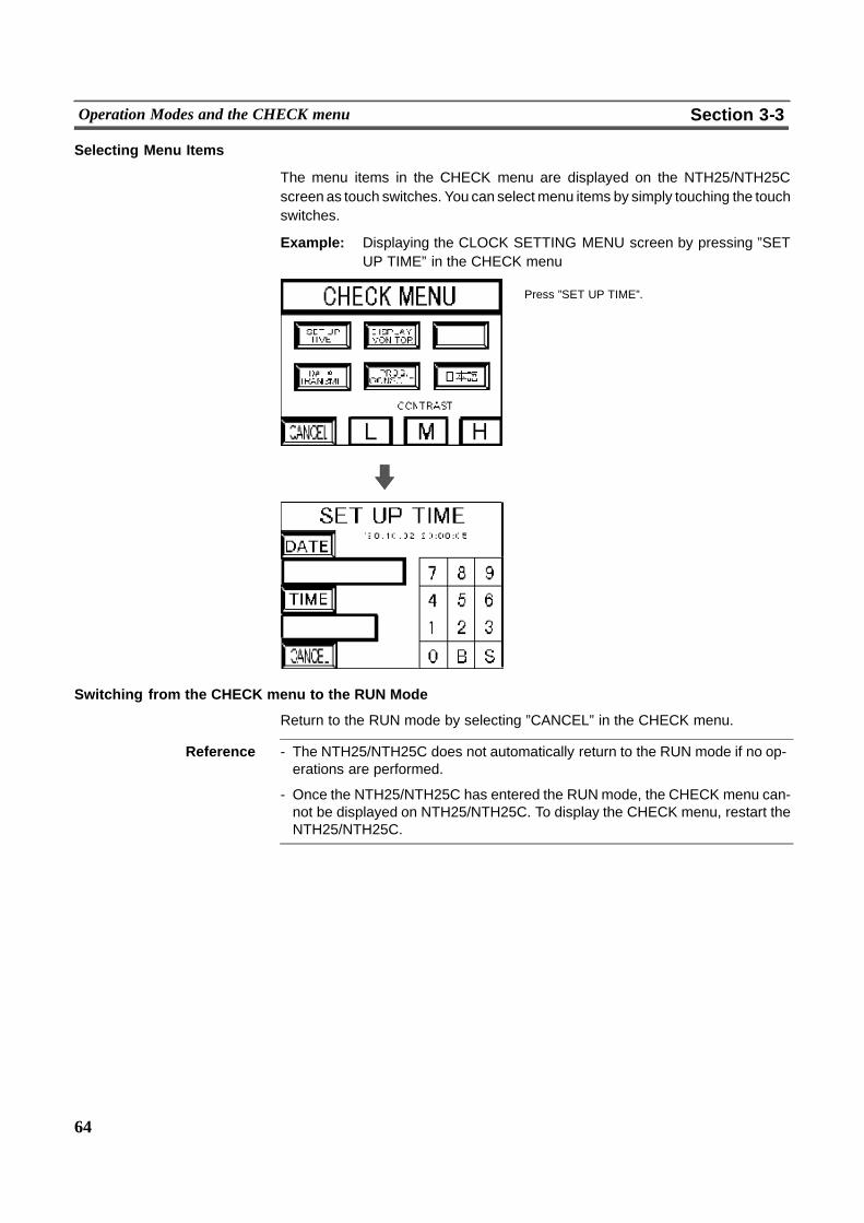
64
Operation Modes and the CHECK menu Section 3-3
Selecting Menu Items
The menu items in the CHECK menu are displayed on the NTH25/NTH25Cscreen as touch switches. You can selectmenu items by simply touching the touchswitches.
Example: Displaying the CLOCK SETTING MENU screen by pressing ”SETUP TIME” in the CHECK menu
Press ”SET UP TIME”.
Switching from the CHECK menu to the RUN Mode
Return to the RUN mode by selecting ”CANCEL” in the CHECK menu.
Reference - The NTH25/NTH25C does not automatically return to the RUN mode if no op-erations are performed.
- Once the NTH25/NTH25C has entered the RUNmode, the CHECK menu can-not be displayed on NTH25/NTH25C. To display the CHECK menu, restart theNTH25/NTH25C.
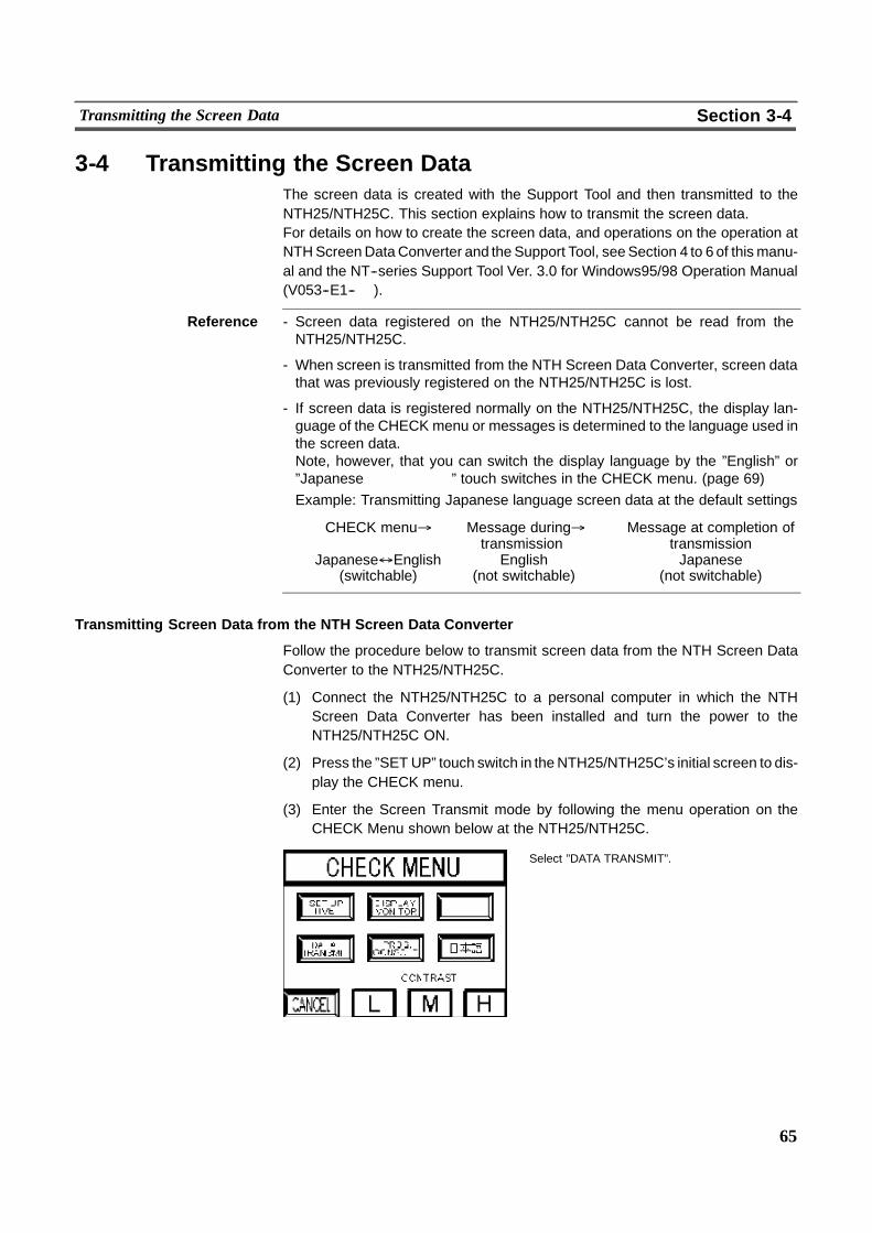
65
Transmitting the Screen Data Section 3-4
3-4 Transmitting the Screen DataThe screen data is created with the Support Tool and then transmitted to theNTH25/NTH25C. This section explains how to transmit the screen data.For details on how to create the screen data, and operations on the operation atNTHScreenDataConverter and the Support Tool, seeSection 4 to 6 of thismanu-al and the NT--series Support Tool Ver. 3.0 for Windows95/98 Operation Manual(V053--E1--� ).
Reference - Screen data registered on the NTH25/NTH25C cannot be read from theNTH25/NTH25C.
- When screen is transmitted from the NTH Screen Data Converter, screen datathat was previously registered on the NTH25/NTH25C is lost.
- If screen data is registered normally on the NTH25/NTH25C, the display lan-guage of the CHECK menu or messages is determined to the language used inthe screen data.Note, however, that you can switch the display language by the ”English” or”Japanese����� ” touch switches in the CHECK menu. (page 69)Example: Transmitting Japanese language screen data at the default settings
CHECK menu% Message during% Message at completion oftransmission transmission
Japanese$English English Japanese(switchable) (not switchable) (not switchable)
Transmitting Screen Data from the NTH Screen Data Converter
Follow the procedure below to transmit screen data from the NTH Screen DataConverter to the NTH25/NTH25C.
(1) Connect the NTH25/NTH25C to a personal computer in which the NTHScreen Data Converter has been installed and turn the power to theNTH25/NTH25C ON.
(2) Press the ”SET UP” touch switch in theNTH25/NTH25C’s initial screen to dis-play the CHECK menu.
(3) Enter the Screen Transmit mode by following the menu operation on theCHECK Menu shown below at the NTH25/NTH25C.
Select ”DATA TRANSMIT”.
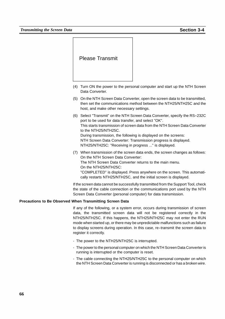
66
Transmitting the Screen Data Section 3-4
Please Transmit
(4) Turn ON the power to the personal computer and start up the NTH ScreenData Converter.
(5) On the NTH Screen Data Converter, open the screen data to be transmitted,then set the communications method between the NTH25/NTH25C and thehost, and make other necessary settings.
(6) Select ”Transmit” on the NTH Screen Data Converter, specify the RS--232Cport to be used for data transfer, and select ”OK”.This starts transmission of screen data from the NTH Screen Data Converterto the NTH25/NTH25C.During transmission, the following is displayed on the screens:NTH Screen Data Converter: Transmission progress is displayed.NTH25/NTH25C: ”Receiving in progress ...” is displayed.
(7) When transmission of the screen data ends, the screen changes as follows:On the NTH Screen Data Converter:The NTH Screen Data Converter returns to the main menu.On the NTH25/NTH25C:”COMPLETED” is displayed. Press anywhere on the screen. This automati-cally restarts NTH25/NTH25C, and the initial screen is displayed.
If the screen data cannot be successfully transmitted from theSupport Tool, checkthe state of the cable connection or the communications port used by the NTHScreen Data Converter (personal computer) for data transmission.
Precautions to Be Observed When Transmitting Screen Data
If any of the following, or a system error, occurs during transmission of screendata, the transmitted screen data will not be registered correctly in theNTH25/NTH25C. If this happens, the NTH25/NTH25C may not enter the RUNmode when started up, or theremay beunpredictable malfunctions such as failureto display screens during operation. In this case, re--transmit the screen data toregister it correctly.
- The power to the NTH25/NTH25C is interrupted.
- The power to the personal computer onwhich theNTHScreenDataConverter isrunning is interrupted or the computer is reset.
- The cable connecting the NTH25/NTH25C to the personal computer on whichtheNTH ScreenData Converter is running is disconnected or has a brokenwire.
67
Starting Operation Section 3-5
3-5 Starting OperationAfter you have finished transmitting screen data, connect the NTH25/NTH25C tothe host and start operation.
Caution Check the operation of all screen data and host programs carefully before usingthem. If their operation is incorrect, the system may operate unpredictably.
Switching to the RUN Mode and Starting Operation
Press the ”Cancel” touch switch on the CHECK menu screen. TheNTH25/NTH25C switches to the RUN mode and starts operation.The operation at the start is as follows.
[Display of the Initial Screen]
First of all, the initial screen that was set to the screen data by the Support Tool isdisplayed.Nothing will be displayed if the screen contents are incorrect, or data has not beenregistered to the currently set screen number.At this stage, communications with the host is not yet established. So, if displayelements that require communications with the host for referencing words allo-cated on the host are in the initial screen, numerical values are expressed as ”0”(zero) and character string are expressed as blank spaces.
[Checking Communications with the Host]
The NTH25/NTH25C waits for communications with the host to be established.If communications is not established within about ten seconds, theNTH25/NTH25C displays the message ”No Reply from Host”.
[Display of the Specified Screen]
The specified screen is displayedwhen the contents (screen number of the screento be displayed) of the first word of the PT status control area are read.The screen will not be switched if the contents of the first word of the PT statuscontrol area are incorrect as a screen number. Also, nothing will be displayed if nodata is registered to the currently set screen number.
68
Starting Operation Section 3-5
Confirming Communications between the NTH25/NTH25C and the Host
Execute the host program and confirm that the following operations are performednormally.
- Confirm that the NTH25/NTH25C screens switch in accordance with the hostprogram.If the screens do not switch correctly, check the connection between the hostand the NTH25/NTH25C, and also check that the hardware settings are correct.For details, see Section 2 ”Connection”.
- Confirm that the operation results of touch switch and numeral input at theNTH25/NTH25C are sent to the host correctly by displaying the contents of thehost words and bits using a peripheral tool (e.g. SYSMAC support software).If the results of operations at the NTH25/NTH25C are not sent to the host cor-rectly, check the setting of the display elements. For details on setting displayelements, see Section 4 ”NTH25/NTH25C Functions”.
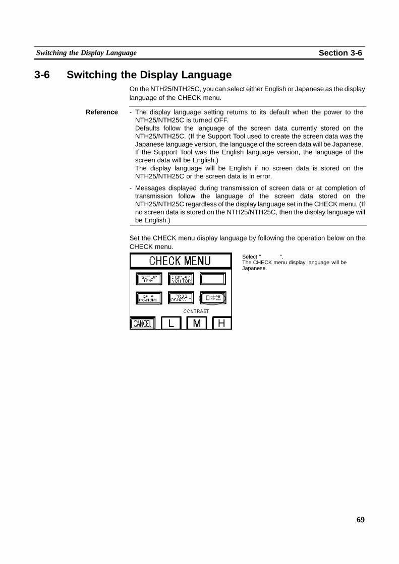
69
Switching the Display Language Section 3-6
3-6 Switching the Display LanguageOn the NTH25/NTH25C, you can select either English or Japanese as the displaylanguage of the CHECK menu.
Reference - The display language setting returns to its default when the power to theNTH25/NTH25C is turned OFF.Defaults follow the language of the screen data currently stored on theNTH25/NTH25C. (If the Support Tool used to create the screen data was theJapanese language version, the language of the screen data will be Japanese.If the Support Tool was the English language version, the language of thescreen data will be English.)The display language will be English if no screen data is stored on theNTH25/NTH25C or the screen data is in error.
- Messages displayed during transmission of screen data or at completion oftransmission follow the language of the screen data stored on theNTH25/NTH25C regardless of the display language set in the CHECK menu. (Ifno screen data is stored on the NTH25/NTH25C, then the display language willbe English.)
Set the CHECK menu display language by following the operation below on theCHECK menu.
Select ”��� ”.The CHECK menu display language will beJapanese.
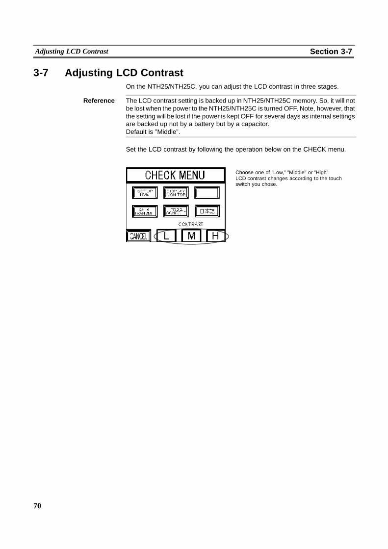
70
Adjusting LCD Contrast Section 3-7
3-7 Adjusting LCD ContrastOn the NTH25/NTH25C, you can adjust the LCD contrast in three stages.
Reference The LCD contrast setting is backed up in NTH25/NTH25C memory. So, it will notbe lost when the power to the NTH25/NTH25C is turned OFF. Note, however, thatthe setting will be lost if the power is kept OFF for several days as internal settingsare backed up not by a battery but by a capacitor.Default is ”Middle”.
Set the LCD contrast by following the operation below on the CHECK menu.
Choose one of ”Low,” ”Middle” or ”High”.LCD contrast changes according to the touchswitch you chose.
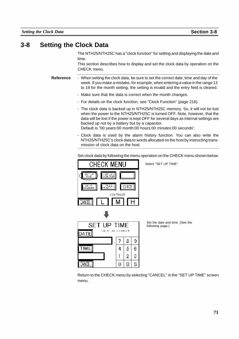
71
Setting the Clock Data Section 3-8
3-8 Setting the Clock DataThe NTH25/NTH25C has a ”clock function” for setting and displaying the date andtime.This section describes how to display and set the clock data by operation on theCHECK menu.
Reference - When setting the clock data, be sure to set the correct date, time and day of theweek. If youmake amistake, for example, whenentering a value in the range 13to 19 for the month setting, the setting is invalid and the entry field is cleared.
- Make sure that the data is correct when the month changes.
- For details on the clock function, see ”Clock Function” (page 216).
- The clock data is backed up in NTH25/NTH25C memory. So, it will not be lostwhen the power to the NTH25/NTH25C is turned OFF. Note, however, that thedata will be lost if the power is kept OFF for several days as internal settings arebacked up not by a battery but by a capacitor.Default is ”00 years:00 month:00 hours:00 minutes:00 seconds”.
- Clock data is used by the alarm history function. You can also write theNTH25/NTH25C’s clock data to words allocated on the host by instructing trans-mission of clock data on the host.
Set clock data by following themenu operation on the CHECKmenu shownbelow.
Select ”SET UP TIME”.
Set the date and time. (See thefollowing page.)
Return to the CHECKmenu by selecting ”CANCEL” in the “SET UP TIME” screenmenu.
72
Setting the Clock Data Section 3-8
3-8-1 Setting the Date and Time! Setting the date
(1) Press ”Date”.You can now enter the date under the ”Date” field.
(2) Enter the date in order ”Year, Month, Day” using the number keys displayedon the right. (”B” stands for Backspace, and ”S” stands for Set.)Year: 4 digits (1980 to 2155*)Month: 2 digits (00 to 12)Day: 2 digits (00 to 31)* The years 2156 to 2158 can be entered. The NTH25/NTH25C, however,may malfunction.
(3) Press the ”S” key. This sets the date and displays it at the top of the screen.Example: December 24, 1998Input: [1998122] % [S] % Display: [1998--12--24]
! Setting the time
(1) Press ”Time”.You can now enter the time under the ”Time” field.
(2) Enter the time in order ”Hour, Minute, Second” using the number keys dis-played on the right. (”B” stands for Backspace, and ”S” stands for Set.)Hour: 2 digits (00 to 24) (In the 24--hour clock system, ”24” becomes ”00”)Minute: 2 digits (00 to 60) (”60” becomes ”00”)Second: 2 digits (00 to 60) (”60” becomes ”00”)
(3) Press the ”S” key. This sets the time and displays it at the top of the screen.
Example: To enter 16 hours:08 minutes;45 secondsInput: [160845] % [S] % Display: [16:08:45]
Reference Though theNTH25/NTH25C checkswhether the date and time that you entered iscorrect or not, be sure to enter the correct clock data.

73
Checking Screen Data Section 3-9
3-9 Checking Screen DataThe NTH25/NTH25C allows the registered screens (Nos. 1 to 1000) to be dis-played and checked by operation on the CHECK menu.
Reference - Window screens cannot be displayed by operation on the CHECKmenu. In theScreenMonitor screen, communications with the host is not performed. So, nu-merical values are expressed as ”0” (zero) and character strings are expressedas blank spaces in the case of display elements that require communicationswith the host for referencingwords allocated on the host. Also, other display ele-ments will not function.
- Only the user screens (Nos. 1 to 1000) can be displayed. Screens for systemuse cannot be displayed.
Display the ScreenMonitor screen by following themenu operation on theCHECKmenu shown below.
Select ”DISPLAY MONITOR”.
Specify the screen number to be checked usingthe number keys displayed on the right. (”B”stands for Backspace, and ”S” stands for Set.)Press the ”S” key. This displays the screen youspecified.If you specified an invalid screen number, ”Error”is displayed. Or, if you specified a screen numberfor which there is no screen data, a screen withoutany display elements is displayed.
T 015003RUN
BOILER OPERATION
T 015301STOP
T 016312ERROR
L 020000
StartConfirmation
StopConfirmation
ErrorOccurrence
L 020005 L 020013
When you have finished checking the screen,press anywhere on the screen to return to theScreen Monitor screen.You can now continue to confirm other screens.
Return to the CHECK menu by selecting ”Cancel” in the “DISPLAY MONITOR”screen.
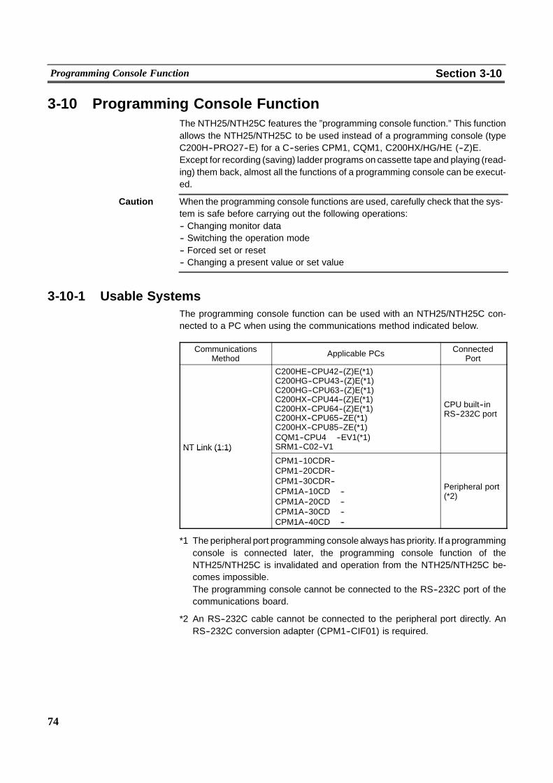
74
Programming Console Function Section 3-10
3-10 Programming Console FunctionThe NTH25/NTH25C features the ”programming console function.” This functionallows the NTH25/NTH25C to be used instead of a programming console (typeC200H--PRO27--E) for a C--series CPM1, CQM1, C200HX/HG/HE (--Z)E.Except for recording (saving) ladder programs on cassette tape and playing (read-ing) them back, almost all the functions of a programming console can be execut-ed.
Caution When the programming console functions are used, carefully check that the sys-tem is safe before carrying out the following operations:-- Changing monitor data-- Switching the operation mode-- Forced set or reset-- Changing a present value or set value
3-10-1 Usable SystemsThe programming console function can be used with an NTH25/NTH25C con-nected to a PC when using the communications method indicated below.
CommunicationsMethod Applicable PCs Connected
Port
NT Link (1:1)
C200HE--CPU42--(Z)E(*1)C200HG--CPU43--(Z)E(*1)C200HG--CPU63--(Z)E(*1)C200HX--CPU44--(Z)E(*1)C200HX--CPU64--(Z)E(*1)C200HX--CPU65--ZE(*1)C200HX--CPU85--ZE(*1)CQM1--CPU4� --EV1(*1)SRM1--C02--V1
CPU built--inRS--232C port
NT Link (1:1)
CPM1--10CDR--�CPM1--20CDR--�CPM1--30CDR--�CPM1A--10CD� --�CPM1A--20CD� --�CPM1A--30CD� --�CPM1A--40CD� --�
Peripheral port(*2)
*1 The peripheral port programming console always has priority. If aprogrammingconsole is connected later, the programming console function of theNTH25/NTH25C is invalidated and operation from the NTH25/NTH25C be-comes impossible.The programming console cannot be connected to the RS--232C port of thecommunications board.
*2 An RS--232C cable cannot be connected to the peripheral port directly. AnRS--232C conversion adapter (CPM1--CIF01) is required.

75
Programming Console Function Section 3-10
Reference Note that the programming console function cannot be used with CPM1, CQM1,and C200HX/HG/HE PCs of the following lot numbers.CPM1:��� 5, �� *6where * is a number in the range 1 to 9 or the letter X or Y.
CQM1: ��� 3, ��� 4, ��� 5, �� *6where * is a number in the range 1 to 9 or the letter X or Y.
C200HX/HG/HE: ��� 5 �� *6where * is a number in the range 1 to 9 or the letter X.
3-10-2 Connection MethodFor CQM1, C200HX/HG/HE(--ZE), SRM1
The connection method is exactly the same as for the NT link (1:1). Make the con-nection to the PC by referring to Section 2 ”Connection”.
For CPM1
The connectionmethod is the same as for the NT link (1:1). Connect theRS--232Ccable to the peripheral port via an RS--232C conversion adapter (CPM1--CIF01).Make the connection to the PC by referring to Section 2 ”Connection”.
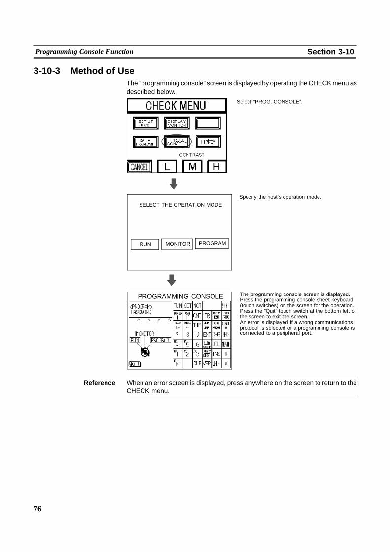
76
Programming Console Function Section 3-10
3-10-3 Method of UseThe ”programming console” screen is displayed by operating theCHECKmenu asdescribed below.
Select ”PROG. CONSOLE”.
Specify the host’s operation mode.
The programming console screen is displayed.Press the programming console sheet keyboard(touch switches) on the screen for the operation.Press the ”Quit” touch switch at the bottom left ofthe screen to exit the screen.An error is displayed if a wrong communicationsprotocol is selected or a programming console isconnected to a peripheral port.
PROGRAMMING CONSOLE
SELECT THE OPERATION MODE
RUN PROGRAMMONITOR
Reference When an error screen is displayed, press anywhere on the screen to return to theCHECK menu.
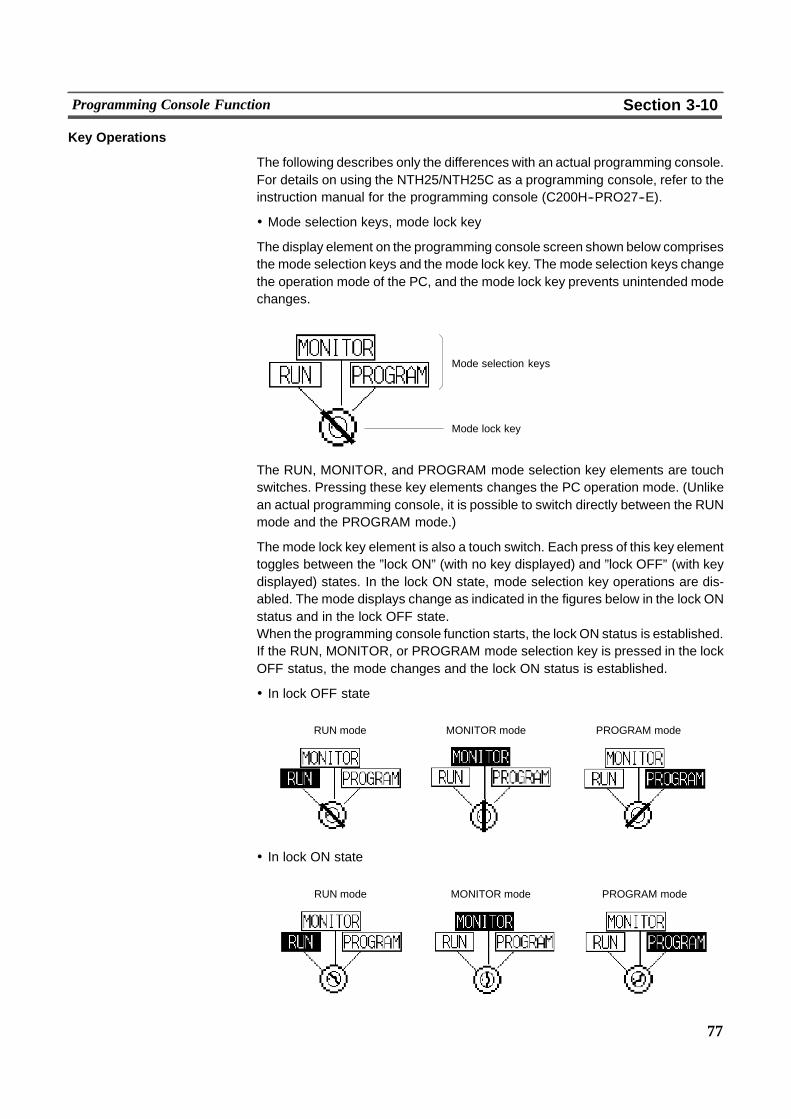
77
Programming Console Function Section 3-10
Key Operations
The following describes only the differences with an actual programming console.For details on using the NTH25/NTH25C as a programming console, refer to theinstruction manual for the programming console (C200H--PRO27--E).
! Mode selection keys, mode lock key
The display element on the programming console screen shown below comprisesthe mode selection keys and the mode lock key. The mode selection keys changethe operation mode of the PC, and the mode lock key prevents unintended modechanges.
Mode selection keys
Mode lock key
The RUN, MONITOR, and PROGRAM mode selection key elements are touchswitches. Pressing these key elements changes the PC operation mode. (Unlikean actual programming console, it is possible to switch directly between the RUNmode and the PROGRAM mode.)
The mode lock key element is also a touch switch. Each press of this key elementtoggles between the ”lock ON” (with no key displayed) and ”lock OFF” (with keydisplayed) states. In the lock ON state, mode selection key operations are dis-abled. The mode displays change as indicated in the figures below in the lock ONstatus and in the lock OFF state.When the programming console function starts, the lock ON status is established.If the RUN, MONITOR, or PROGRAM mode selection key is pressed in the lockOFF status, the mode changes and the lock ON status is established.
! In lock OFF state
RUN mode MONITOR mode PROGRAM mode
! In lock ON state
RUN mode MONITOR mode PROGRAM mode
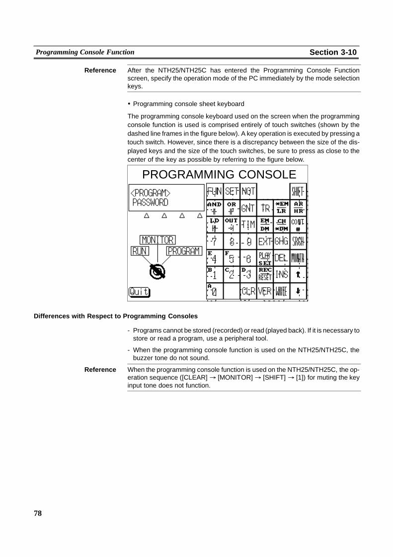
78
Programming Console Function Section 3-10
Reference After the NTH25/NTH25C has entered the Programming Console Functionscreen, specify the operation mode of the PC immediately by the mode selectionkeys.
! Programming console sheet keyboard
The programming console keyboard used on the screen when the programmingconsole function is used is comprised entirely of touch switches (shown by thedashed line frames in the figure below). A key operation is executed by pressing atouch switch. However, since there is a discrepancy between the size of the dis-played keys and the size of the touch switches, be sure to press as close to thecenter of the key as possible by referring to the figure below.
PROGRAMMING CONSOLE
Differences with Respect to Programming Consoles
- Programs cannot be stored (recorded) or read (played back). If it is necessary tostore or read a program, use a peripheral tool.
- When the programming console function is used on the NTH25/NTH25C, thebuzzer tone do not sound.
Reference When the programming console function is used on the NTH25/NTH25C, the op-eration sequence ([CLEAR] % [MONITOR]% [SHIFT] % [1]) for muting the keyinput tone does not function.
79
SECTION 4NTH25/NTH25C Functions
This section describes the functions of the NTH25/NTH25C.
4-1 PT Configuration Settings 80. . . . . . . . . . . . . . . . . . . . . . . . . . . . . . . . . . . . . . . . . . . . . . . . . . . . . .4-1-1 Support Tool ”PT Configuration” Settings 80. . . . . . . . . . . . . . . . . . . . . . . . . . . . . . . . . . .4-1-2 NTH Screen Data Converter ”Configuration” Settings 82. . . . . . . . . . . . . . . . . . . . . . . . . .
4-2 NTH25/NTH25C Screen 83. . . . . . . . . . . . . . . . . . . . . . . . . . . . . . . . . . . . . . . . . . . . . . . . . . . . . . .4-2-1 Screen Composition 83. . . . . . . . . . . . . . . . . . . . . . . . . . . . . . . . . . . . . . . . . . . . . . . . . . . . .4-2-2 Screen Numbers 83. . . . . . . . . . . . . . . . . . . . . . . . . . . . . . . . . . . . . . . . . . . . . . . . . . . . . . . .4-2-3 Screen Types 83. . . . . . . . . . . . . . . . . . . . . . . . . . . . . . . . . . . . . . . . . . . . . . . . . . . . . . . . . .4-2-4 Color Display 85. . . . . . . . . . . . . . . . . . . . . . . . . . . . . . . . . . . . . . . . . . . . . . . . . . . . . . . . . .4-2-5 Display Elements 87. . . . . . . . . . . . . . . . . . . . . . . . . . . . . . . . . . . . . . . . . . . . . . . . . . . . . . .
4-3 Areas for Control/Notification 89. . . . . . . . . . . . . . . . . . . . . . . . . . . . . . . . . . . . . . . . . . . . . . . . . .4-3-1 PT Status Control Area (Host$ NTH25/NTH25C) 90. . . . . . . . . . . . . . . . . . . . . . . . . . .4-3-2 PT Status Notify Area (NTH25/NTH25C to Host) 93. . . . . . . . . . . . . . . . . . . . . . . . . . . . .4-3-3 Window Control Area 95. . . . . . . . . . . . . . . . . . . . . . . . . . . . . . . . . . . . . . . . . . . . . . . . . . .4-3-4 Trend Graph Control Area (host to NTH25/NTH25C) 96. . . . . . . . . . . . . . . . . . . . . . . . . .
4-4 Memory Tables 98. . . . . . . . . . . . . . . . . . . . . . . . . . . . . . . . . . . . . . . . . . . . . . . . . . . . . . . . . . . . . .4-4-1 Numeral Memory Tables 98. . . . . . . . . . . . . . . . . . . . . . . . . . . . . . . . . . . . . . . . . . . . . . . . .4-4-2 Character String Memory Tables 101. . . . . . . . . . . . . . . . . . . . . . . . . . . . . . . . . . . . . . . . . . .4-4-3 Bit Memory Tables 103. . . . . . . . . . . . . . . . . . . . . . . . . . . . . . . . . . . . . . . . . . . . . . . . . . . . .
4-5 Fixed Displays 109. . . . . . . . . . . . . . . . . . . . . . . . . . . . . . . . . . . . . . . . . . . . . . . . . . . . . . . . . . . . . . .4-5-1 Circles, Arcs, Sectors, Polylines, Polygons, Rectangles(fixed displays) 109. . . . . . . . . . . . . . . . . . . . . . . . . . . . . . . . . . . . . . . . . . . . . . . . . . . . . . . . . . . . . .4-5-2 Text (Fixed Display) 119. . . . . . . . . . . . . . . . . . . . . . . . . . . . . . . . . . . . . . . . . . . . . . . . . . . .4-5-3 Tiling 123. . . . . . . . . . . . . . . . . . . . . . . . . . . . . . . . . . . . . . . . . . . . . . . . . . . . . . . . . . . . . . . .4-5-4 Marks 126. . . . . . . . . . . . . . . . . . . . . . . . . . . . . . . . . . . . . . . . . . . . . . . . . . . . . . . . . . . . . . . .
4-6 Image and Library Data 130. . . . . . . . . . . . . . . . . . . . . . . . . . . . . . . . . . . . . . . . . . . . . . . . . . . . . . .4-6-1 Image Data Display 130. . . . . . . . . . . . . . . . . . . . . . . . . . . . . . . . . . . . . . . . . . . . . . . . . . . . .4-6-2 Library Data Display 134. . . . . . . . . . . . . . . . . . . . . . . . . . . . . . . . . . . . . . . . . . . . . . . . . . . .
4-7 Lamps 137. . . . . . . . . . . . . . . . . . . . . . . . . . . . . . . . . . . . . . . . . . . . . . . . . . . . . . . . . . . . . . . . . . . . .4-8 Touch Switches 145. . . . . . . . . . . . . . . . . . . . . . . . . . . . . . . . . . . . . . . . . . . . . . . . . . . . . . . . . . . . . .4-9 Numeral Display 159. . . . . . . . . . . . . . . . . . . . . . . . . . . . . . . . . . . . . . . . . . . . . . . . . . . . . . . . . . . . .4-10 Character String Display 166. . . . . . . . . . . . . . . . . . . . . . . . . . . . . . . . . . . . . . . . . . . . . . . . . . . . . . .4-11 Graphs 172. . . . . . . . . . . . . . . . . . . . . . . . . . . . . . . . . . . . . . . . . . . . . . . . . . . . . . . . . . . . . . . . . . . . .
4-11-1 Bar Graphs 172. . . . . . . . . . . . . . . . . . . . . . . . . . . . . . . . . . . . . . . . . . . . . . . . . . . . . . . . . . . .4-11-2 Trend Graphs 176. . . . . . . . . . . . . . . . . . . . . . . . . . . . . . . . . . . . . . . . . . . . . . . . . . . . . . . . . .
4-12 Alarm List, Alarm History 189. . . . . . . . . . . . . . . . . . . . . . . . . . . . . . . . . . . . . . . . . . . . . . . . . . . . .4-13 Inputting Numerals 196. . . . . . . . . . . . . . . . . . . . . . . . . . . . . . . . . . . . . . . . . . . . . . . . . . . . . . . . . . .
4-13-1Numeral key type (”Numeral Input”) 196. . . . . . . . . . . . . . . . . . . . . . . . . . . . . . . . . . . . . . .4-13-2Thumbwheel Type (Thumbwheel) 203. . . . . . . . . . . . . . . . . . . . . . . . . . . . . . . . . . . . . . . . . .
4-14 Special Functions 211. . . . . . . . . . . . . . . . . . . . . . . . . . . . . . . . . . . . . . . . . . . . . . . . . . . . . . . . . . . .4-14-1Window Function 211. . . . . . . . . . . . . . . . . . . . . . . . . . . . . . . . . . . . . . . . . . . . . . . . . . . . . . .4-14-2Function Switches 214. . . . . . . . . . . . . . . . . . . . . . . . . . . . . . . . . . . . . . . . . . . . . . . . . . . . . .4-14-3Backlight OFF Function 215. . . . . . . . . . . . . . . . . . . . . . . . . . . . . . . . . . . . . . . . . . . . . . . . .4-14-4Clock Function 216. . . . . . . . . . . . . . . . . . . . . . . . . . . . . . . . . . . . . . . . . . . . . . . . . . . . . . . . .4-14-5Programming Console Function (Expansion Function) 217. . . . . . . . . . . . . . . . . . . . . . . . .

80
PT Configuration Settings Section 4-1
4-1 PT Configuration SettingsThe basic operation of the NTH25/NTH25C is determined by the ”PT Configura-tion” settings made on the Support Tool and ”Configuration” on the NTH ScreenData Converter.
This section describes the settings made under ”PT Configuration” and ”Configu-ration”. However, note that the operations on the Support Tool are not described.For details on these operations, see the NT--series Support Tool Ver. 3.0 for Win-dows95/98 Operation Manual (V053--E1--� ) or Section 6 ”NTH Screen Data Con-verter”.
4-1-1 Support Tool ”PT Configuration” SettingsThe Support Tool has the following PT Configuration settings:
Only sections enclosed by are valid.
[PT Model]
Set the model of PT to be connected and type of screen data to be created. Set asfollows for whichever of NTH25/NTH25C is being used:
NTH25 in use: NT31 (Do not select NT31--V1.)NTH25C in use: NT31C (Do not select NT31C--V1.)
[Comments]
Set a comment relating to the screen data here. This comment is valid only withinthe Support Tool, and cannot be displayed on the NTH25/NTH25C.
[PT Control/Notify Area]
Set the allocated words for the PT status control area and PT status notify areahere. See ”4--3 Areas for Control/Notification” (page 89).

81
PT Configuration Settings Section 4-1
[Initial Screen]
Set the screen number of the screen that is displayed when NTH25/NTH25C op-eration starts. Note, however, that the screen number switches to the screen num-ber written to the ”screen switch setting” word in the PT status control area whencommunications with the host is begun. For details, see ”Functions of the PT Sta-tus Control Area” (page 91).
[History Setting]
This setting is invalid when the NTH25/NTH25C is used.
[Number of Table Entries]
This setting is invalid when the NTH25/NTH25C is used.
[Numeral Storage Type]
Set whether the contents of words allocated on the host are handled collectively asBCD data or binary data. However, the numeral storage type set here is valid onlywhen ”System” is set for ”Storage Type” for each numeral memory table con-cerned.
Storage Type and Recognizable Numerals
When the contents of words allocated on the host are displayed in numeral displayelements, for example, numerals are interpreted according to the ”NumeralStrageType”. The numeral storage type setting changes how theNTH25/NTH25C recog-nizes numerals even if the contents of the word are the same.
BCD data format:
The contents of words on the host are interpreted as BCD (Binary CodedDecimal) values. Note, however, that the ”--” sign cannot be input to wordson the host. So, the contents of words whose uppermost digit is ”F” aretreated as a negative value.If ”A” to ”E” are stored to the uppermost digit of a word on the host, or if ”A” to”F” are stored to digits other than the uppermost digit, conversion or displaywill be in error. For example, those digits only will be calculated as beinghexadecimal values.
Binary data format:
The contents of words on the host are interpreted as signed binary data.In this format, the uppermost bit is a sign bit. (When the bit is 1, this indicatesthat the contents of words are a negative value.)When the allocated word isone word, bit 15 is the sign bit, and when two words, bit 31 is the sign bit.
82
PT Configuration Settings Section 4-1
4-1-2 NTH Screen Data Converter ”Configuration” SettingsThe NTH Screen Data Converter has the following Configuration settings. For de-tails on settings and operations, see ”Configuration”, page 260.
Reference When ”NT Link” is set to ”Comm. Method” on the [Initialize] page, communicationcannot be set. If set to ”Memory Link”, the PLC Setting cannot be set.
! [Initialize] Page
-- Model (PT type)
NTH25, NTH25C
-- Auto CFL off (backlight auto OFF--ON/OFF and auto OFF time)
0: Auto OFF is OFF (PT status control bit ”backlight mode” is enabled)1 to 99: 1 to 99 minutes (PT status control bit ”backlight mode” is disabled)
-- Comm. Method (communications method used for communications between
NTH25/NTH25C and host)Host link, memory link, NT link (1:1)
! [Communication] page
-- Baud rate (communications speed)
1200, 2400, 4800, 9600, 19200
-- Stop bit (stop bit length)
1, 2
-- Data length
7, 8
-- Parity (ON/OFF, type)
Even, odd, none
! [PLC Setting] page
-- PLC Model (type of PC connected to NTH25/NTH25C)
SYSMAC--C (C series PC, SRM1), SYSMAC--CV/CS1 (CVM1/CV/CS1 seriesPC)
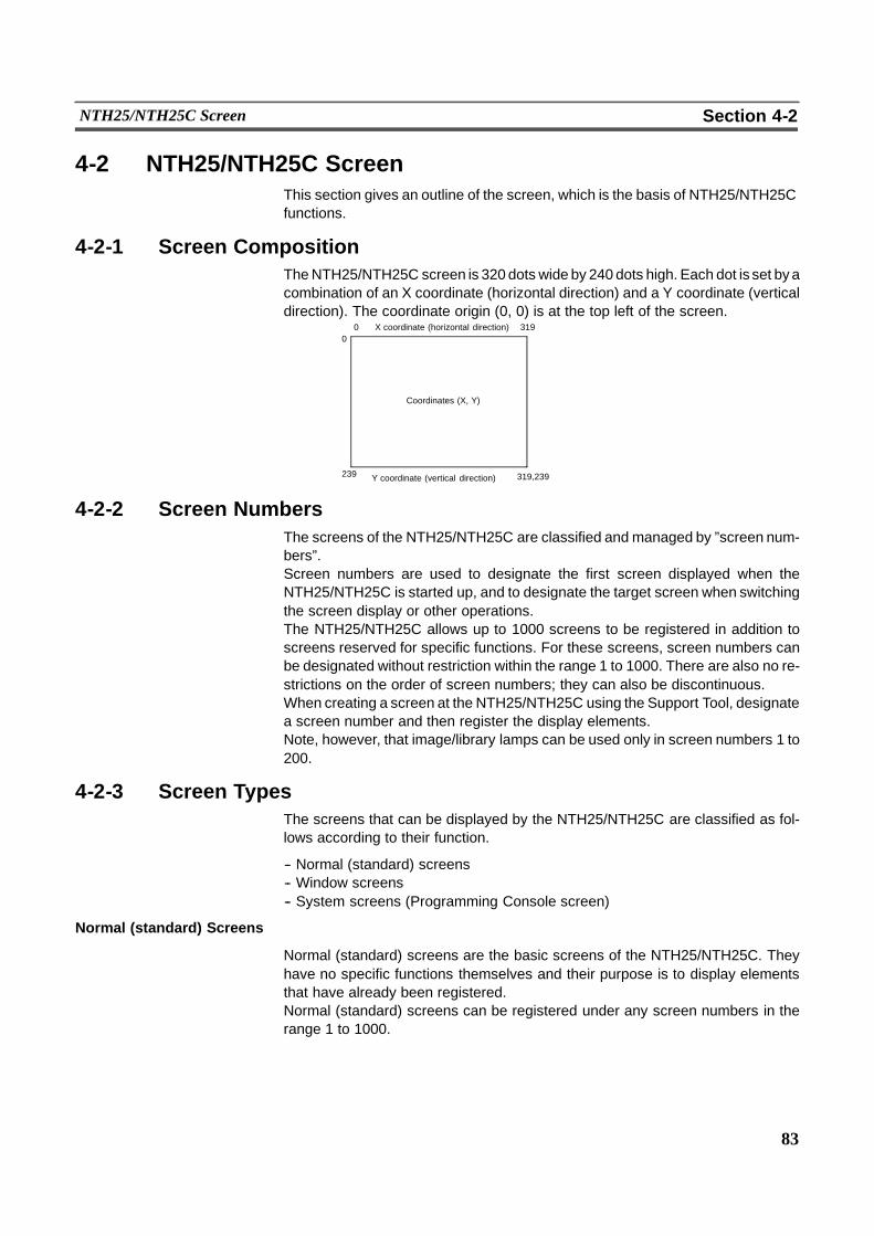
83
NTH25/NTH25C Screen Section 4-2
4-2 NTH25/NTH25C ScreenThis section gives an outline of the screen, which is the basis of NTH25/NTH25Cfunctions.
4-2-1 Screen CompositionTheNTH25/NTH25C screen is 320 dots wide by 240 dots high. Each dot is set byacombination of an X coordinate (horizontal direction) and a Y coordinate (verticaldirection). The coordinate origin (0, 0) is at the top left of the screen.
31900
239 319,239
X coordinate (horizontal direction)
Y coordinate (vertical direction)
Coordinates (X, Y)
4-2-2 Screen NumbersThe screens of the NTH25/NTH25C are classified and managed by ”screen num-bers”.Screen numbers are used to designate the first screen displayed when theNTH25/NTH25C is started up, and to designate the target screen when switchingthe screen display or other operations.The NTH25/NTH25C allows up to 1000 screens to be registered in addition toscreens reserved for specific functions. For these screens, screen numbers canbe designated without restriction within the range 1 to 1000. There are also no re-strictions on the order of screen numbers; they can also be discontinuous.When creating a screen at the NTH25/NTH25C using the Support Tool, designatea screen number and then register the display elements.Note, however, that image/library lamps can be used only in screen numbers 1 to200.
4-2-3 Screen TypesThe screens that can be displayed by the NTH25/NTH25C are classified as fol-lows according to their function.
-- Normal (standard) screens-- Window screens-- System screens (Programming Console screen)
Normal (standard) Screens
Normal (standard) screens are the basic screens of the NTH25/NTH25C. Theyhave no specific functions themselves and their purpose is to display elementsthat have already been registered.Normal (standard) screens can be registered under any screen numbers in therange 1 to 1000.

84
NTH25/NTH25C Screen Section 4-2
Window Screens
By the normal (standard) screen display method, a screen is displayed over theentire panel area. In addition to this display method, the NTH25/NTH25C also al-lows screens to be displayed in only one part of the screen area. This partialscreen is called a ”window”, and a screen to which a window is registered is calleda ”window screen”.
Up to 20 window screens can be registered under any screen number in the range1 to 1000. However, screens that are registered aswindow screens cannot be dis-played independently like normal (standard) screens.
7 8 9 4 5 6 .1 2 3 0
Base screen
Keypad
Touch switch for openingthe window Window displayed on the screen at
the registered size and position
Window screen
Window area
Keypad
7 8 9 4 5 6 .1 2 3 0
Windows can be called anytime by operating a touch switch, regardless of whichscreen is currently displayed. It is also possible to open and close windows by thecontrol from the host.For details, see ”Window Functions” (page 211).
System Screens
Screens with predetermined functions are called ”system screens”.The table below shows the type of system screen:
Screen number Name Function
9020 Programmingconsole func-tion screen
As an extended function, the NTH25/NTH25C fea-tures the ”programming console” function, whichenables equivalent functions to those of a pro-gramming console. When the NTH25/NTH25C isconnected to a host which supports the program-ming console function, it can be used in place ofthe programming console by designating screennumber 9020 as the display screen.
For details on the programming console function, see 3--10 ”Programming Con-sole Function” (page 74).
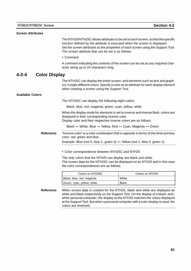
85
NTH25/NTH25C Screen Section 4-2
Screen Attributes
TheNTH25/NTH25C allows attributes to be set to each screen, so that the specificfunction defined by the attribute is executed when the screen is displayed.Set the screen attributes as the properties of each screen using the Support Tool.The screen attribute that can be set is as follows.
! Comment
A comment indicating the contents of the screen can be set as any required char-acter string up to 24 characters long.
4-2-4 Color DisplayThe NTH25C can display the entire screen, and elements such as text and graph-ics, in eight different colors. Specify a color as an attribute for each display elementwhen creating a screen using the Support Tool.
Available Colors
The NTH25C can display the following eight colors:
Black, blue, red, magenta, green, cyan, yellow, white
When the display mode for elements is set to inverse and inverse flash, colors aredisplayed in their corresponding inverse color.Display color and their respective inverse colors are as follows:
Black $ White, Blue$ Yellow, Red$ Cyan, Magenta $ Green
Reference ”Inverse color” is a color combination that is opposite in terms of the three primarycolor: red, green and blue.Example: Blue (red 0, blue 1, green 0)$ Yellow (red 1, blue 0, green 1)
! Color correspondence between NTH25C and NTH25
The only colors that the NTH25 can display are black and white.The screen data for the NTH25C can be displayed on an NTH25 and in this casethe color correspondences are as follows.
Colors on NTH25C Colors on NTH25
Black, blue, red, magenta White
Green, cyan, yellow, white Black
Reference When screen data is created for the NTH25, black and white are displayed aswhite and black respectively on the Support Tool. On the display of a black--and--white personal computer, the display at the NTH25 matches the colors displayedat the Support Tool. But when apersonal computer with a color display is used, thecolors are reversed.
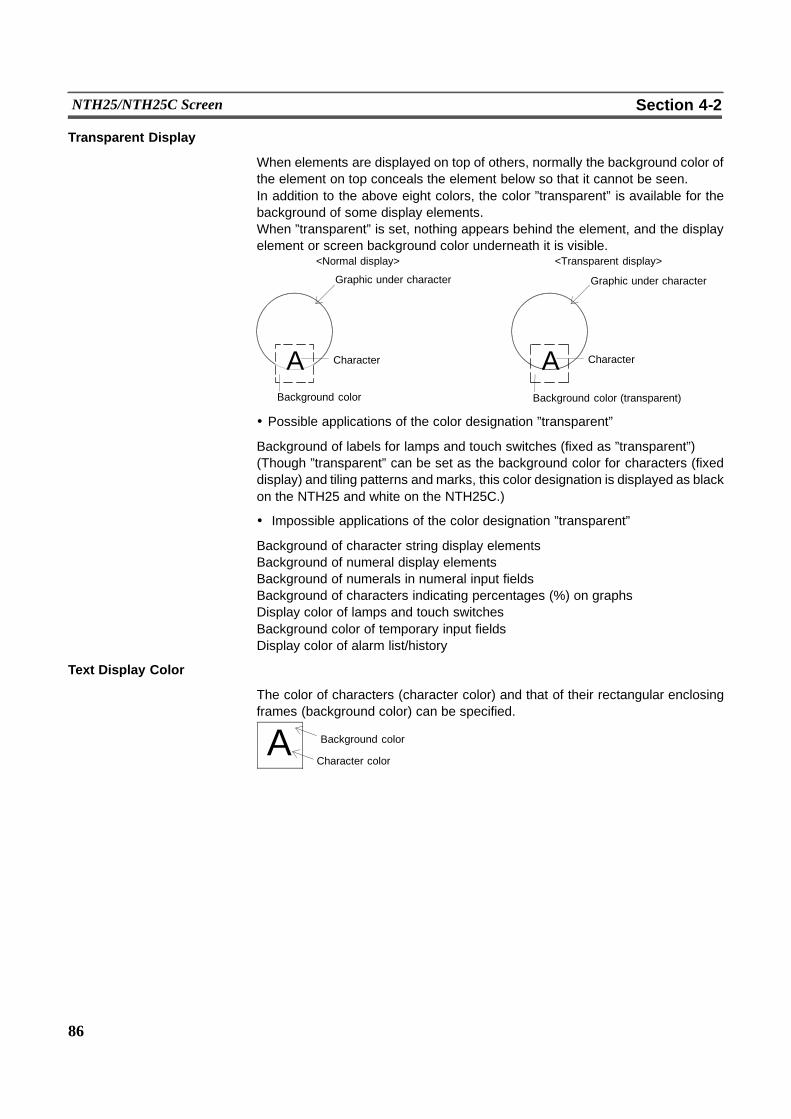
86
NTH25/NTH25C Screen Section 4-2
Transparent Display
When elements are displayed on top of others, normally the background color ofthe element on top conceals the element below so that it cannot be seen.In addition to the above eight colors, the color ”transparent” is available for thebackground of some display elements.When ”transparent” is set, nothing appears behind the element, and the displayelement or screen background color underneath it is visible.
A A
Graphic under character Graphic under character
Character Character
Background color Background color (transparent)
<Normal display> <Transparent display>
! Possible applications of the color designation ”transparent”
Background of labels for lamps and touch switches (fixed as ”transparent”)(Though ”transparent” can be set as the background color for characters (fixeddisplay) and tiling patterns and marks, this color designation is displayed as blackon the NTH25 and white on the NTH25C.)
! Impossible applications of the color designation ”transparent”
Background of character string display elementsBackground of numeral display elementsBackground of numerals in numeral input fieldsBackground of characters indicating percentages (%) on graphsDisplay color of lamps and touch switchesBackground color of temporary input fieldsDisplay color of alarm list/history
Text Display Color
The color of characters (character color) and that of their rectangular enclosingframes (background color) can be specified.
A Background color
Character color
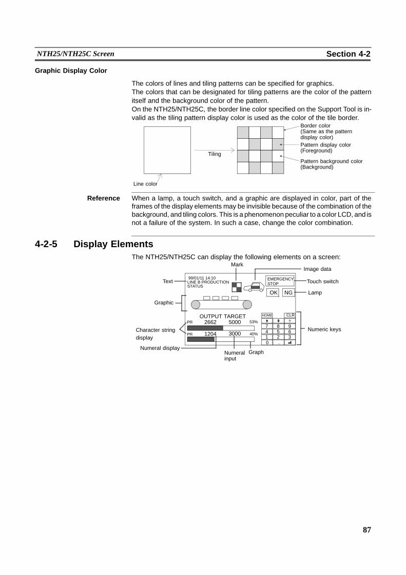
87
NTH25/NTH25C Screen Section 4-2
Graphic Display Color
The colors of lines and tiling patterns can be specified for graphics.The colors that can be designated for tiling patterns are the color of the patternitself and the background color of the pattern.On the NTH25/NTH25C, the border line color specified on the Support Tool is in-valid as the tiling pattern display color is used as the color of the tile border.
Border color(Same as the patterndisplay color)Pattern display color(Foreground)
TilingPattern background color(Background)
Line color
Reference When a lamp, a touch switch, and a graphic are displayed in color, part of theframes of the display elements may be invisible because of the combination of thebackground, and tiling colors. This is a phenomenon peculiar to a color LCD, and isnot a failure of the system. In such a case, change the color combination.
4-2-5 Display ElementsThe NTH25/NTH25C can display the following elements on a screen:
MarkImage data
Touch switch
Graphic
Lamp
Character stringdisplay
Numeric keys
Graph
Text
Numeral displayNumeralinput
EMERGENCYSTOP
OK NG
99/01/11 14:10LINE B PRODUCTIONSTATUS
OUTPUT TARGETPR
PR
2662
1204
5000
3000
53%
40%
0147
.258
369
HOME CLR
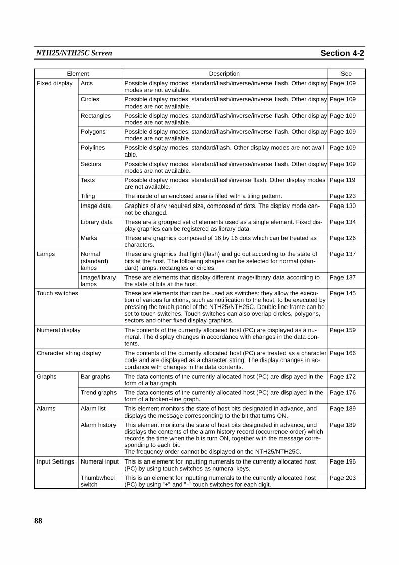
88
NTH25/NTH25C Screen Section 4-2
Element Description See
Fixed display Arcs Possible display modes: standard/flash/inverse/inverse flash. Other displaymodes are not available.
Page 109
Circles Possible display modes: standard/flash/inverse/inverse flash. Other displaymodes are not available.
Page 109
Rectangles Possible display modes: standard/flash/inverse/inverse flash. Other displaymodes are not available.
Page 109
Polygons Possible display modes: standard/flash/inverse/inverse flash. Other displaymodes are not available.
Page 109
Polylines Possible display modes: standard/flash. Other display modes are not avail-able.
Page 109
Sectors Possible display modes: standard/flash/inverse/inverse flash. Other displaymodes are not available.
Page 109
Texts Possible display modes: standard/flash/inverse flash. Other display modesare not available.
Page 119
Tiling The inside of an enclosed area is filled with a tiling pattern. Page 123
Image data Graphics of any required size, composed of dots. The display mode can-not be changed.
Page 130
Library data These are a grouped set of elements used as a single element. Fixed dis-play graphics can be registered as library data.
Page 134
Marks These are graphics composed of 16 by 16 dots which can be treated ascharacters.
Page 126
Lamps Normal(standard)lamps
These are graphics that light (flash) and go out according to the state ofbits at the host. The following shapes can be selected for normal (stan-dard) lamps: rectangles or circles.
Page 137
Image/librarylamps
These are elements that display different image/library data according tothe state of bits at the host.
Page 137
Touch switches These are elements that can be used as switches: they allow the execu-tion of various functions, such as notification to the host, to be executed bypressing the touch panel of the NTH25/NTH25C. Double line frame can beset to touch switches. Touch switches can also overlap circles, polygons,sectors and other fixed display graphics.
Page 145
Numeral display The contents of the currently allocated host (PC) are displayed as a nu-meral. The display changes in accordance with changes in the data con-tents.
Page 159
Character string display The contents of the currently allocated host (PC) are treated as a charactercode and are displayed as a character string. The display changes in ac-cordance with changes in the data contents.
Page 166
Graphs Bar graphs The data contents of the currently allocated host (PC) are displayed in theform of a bar graph.
Page 172
Trend graphs The data contents of the currently allocated host (PC) are displayed in theform of a broken--line graph.
Page 176
Alarms Alarm list This element monitors the state of host bits designated in advance, anddisplays the message corresponding to the bit that turns ON.
Page 189
Alarm history This element monitors the state of host bits designated in advance, anddisplays the contents of the alarm history record (occurrence order) whichrecords the time when the bits turn ON, together with the message corre-sponding to each bit.The frequency order cannot be displayed on the NTH25/NTH25C.
Page 189
Input Settings Numeral input This is an element for inputting numerals to the currently allocated host(PC) by using touch switches as numeral keys.
Page 196
Thumbwheelswitch
This is an element for inputting numerals to the currently allocated host(PC) by using ”+” and ”--” touch switches for each digit.
Page 203
89
Areas for Control/Notification Section 4-3
4-3 Areas for Control/NotificationThe following areas are provided for the controlling and exchanging informationrelating to a PT (such as changes in status) between the NTH25/NTH25C and thehost.
! PT status control area
This area is used to designate the screen to be displayed on the NTH25/NTH25C,to notify the host of the currently displayed screen number, to copy data contentsbetween memory tables in the NTH25/NTH25C, and to control the status of thebacklight and other statuses.Allocate the PT status control area to the host on the Support Tool.
! PT status notify area
This area is used to notify the host of the memory table number when there is achange in the data contents of a memory table in the NTH25/NTH25C, and tonotify the host of information such as changes in the PT status.Allocate the PT status notify area to the host on the Support Tool.
! Window control area
This is work area used by the host for controlling windows. When windows areused, more than the required number of window control areas (maximum 20areas) must be allocated to the host.Allocate the window area to the host on the NTH Screen Data Converter.
! Trend graph control area
This area is for stopping and continuing sampling (reading the contents of wordson the host) of trend graphs and clearing past trend graph records.Allocate the trend graph control area to the host on the NTHScreen DataConvert-er.
Reference - The PT status control area and PT status notify area must be allocated to thehost.
- The PT status control area, PT status notify area, window control area and trendcontrol area must be allocated so that they do not overlap each other.
- The window control area and trend graph control area must be allocated to thehost when windows and trend graphs are used.
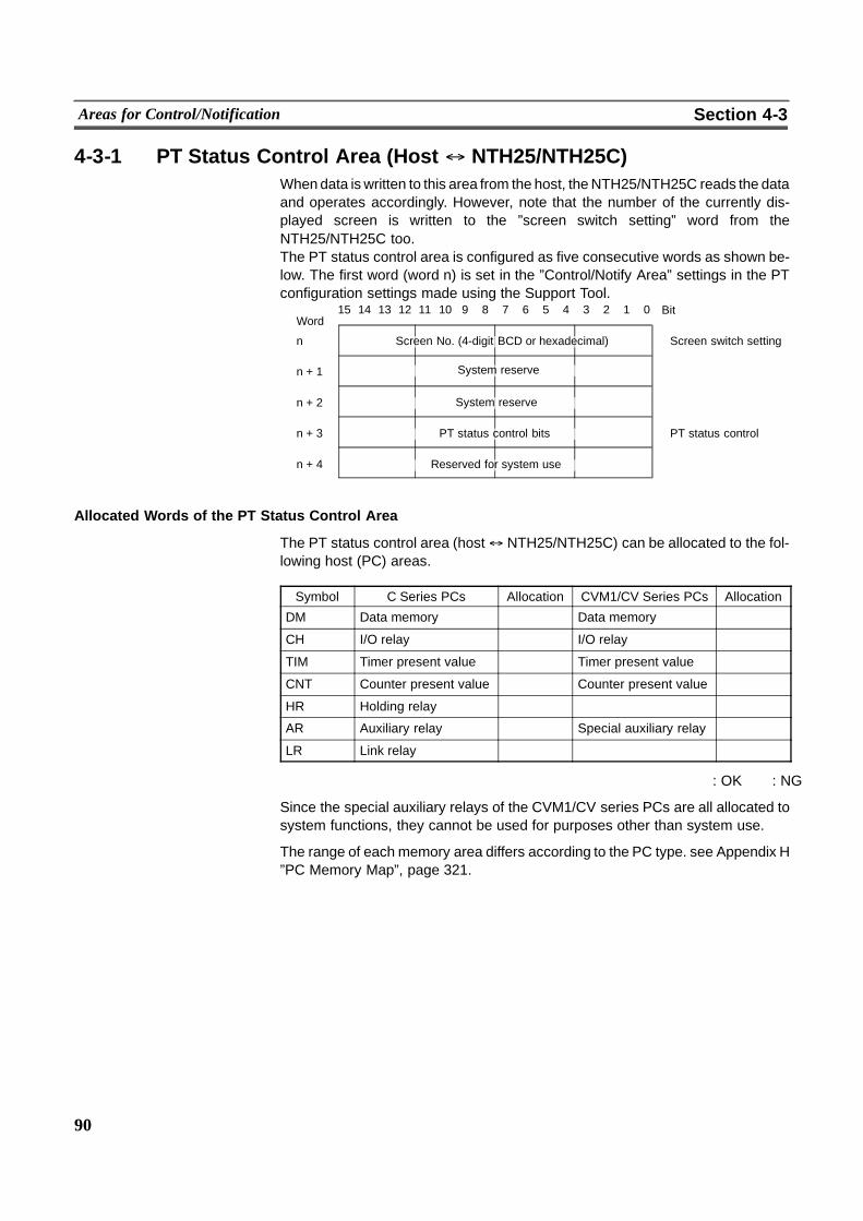
90
Areas for Control/Notification Section 4-3
4-3-1 PT Status Control Area (Host $ NTH25/NTH25C)Whendata is written to this area from the host, theNTH25/NTH25C reads the dataand operates accordingly. However, note that the number of the currently dis-played screen is written to the ”screen switch setting” word from theNTH25/NTH25C too.The PT status control area is configured as five consecutive words as shown be-low. The first word (word n) is set in the ”Control/Notify Area” settings in the PTconfiguration settings made using the Support Tool.
15 14 13 12 11 10 9 8 7 6 5 4 3 2 1 0Word
Bit
n Screen No. (4-digit BCD or hexadecimal) Screen switch setting
n + 1 System reserve
n + 2
n + 3 PT status control bits PT status control
n + 4 Reserved for system use
System reserve
Allocated Words of the PT Status Control Area
The PT status control area (host$ NTH25/NTH25C) can be allocated to the fol-lowing host (PC) areas.
Symbol C Series PCs Allocation CVM1/CV Series PCs Allocation
DM Data memory � Data memory �CH I/O relay � I/O relay �TIM Timer present value � Timer present value �CNT Counter present value � Counter present value �HR Holding relay � � �AR Auxiliary relay � Special auxiliary relay �LR Link relay � � �
� : OK � : NG
Since the special auxiliary relays of the CVM1/CV series PCs are all allocated tosystem functions, they cannot be used for purposes other than system use.
The range of each memory area differs according to the PC type. see Appendix H”PC Memory Map”, page 321.

91
Areas for Control/Notification Section 4-3
Functions of the PT Status Control Area
! Screen switch setting
Data is written to the ”screen switch setting” word from both the NTH25/NTH25Cand the host. Themeaning of the data differs according towhether it is written fromthe NTH25/NTH25C or the host. However, if the NTH25/NTH25C is currently op-erating, the number of the screen currently displayed on the NTH25/NTH25C isalways reflected in the ”screen switch setting” word.
! When data is written from the host
To switch the screen displayed at the NTH25/NTH25C by an instruction from thehost, write the screen number, as a 4--digit BCD value, to the ”screen switch set-ting” word. (On theNTH25/NTH25C, screen numbers cannot be specified in hexa-decimal.)
Designated screen
PLCNTH25/NTH25C
" Screen numberPT status control areaScreen switch setting
System reserve
System reserve
PT status control setting
System reserve
[”Screen switch setting” in the PT status control area]15 14 13 12 11 10 9 8 7 6 5 4 3 2 1 0Word Bit
n Screen switch settingScreen number (4--digit BCD)
The screen numbers that can be set are as follows.
BCD Screen
0000 No--display (screen cleared)
0001 to 1000 Screen numbers 1 to 1000
9020 Programming console screen
Reference - The screen can also be switched by touch switch operation (page 145).
- If no elements are registered to the designated screen number, the screen en-ters a no--display state. If a screen of screen number 1001 or onwards is desig-nated, the screen is not switched.
- When operation of NTH25/NTH25C is started, the screen display follows the”Initial Screen” setting made in ”PT Configuration” on the Support Tool. Afterthis, screen display follows the ”screen switch setting” when communications isestablished with the host.
- If the ”screen switch setting” is also invalid (for example, the screen number isnot specified in BCD), the screen is not switched. Also, the screen enters a no--display state if a screen number to which screen data is not registered is speci-fied.
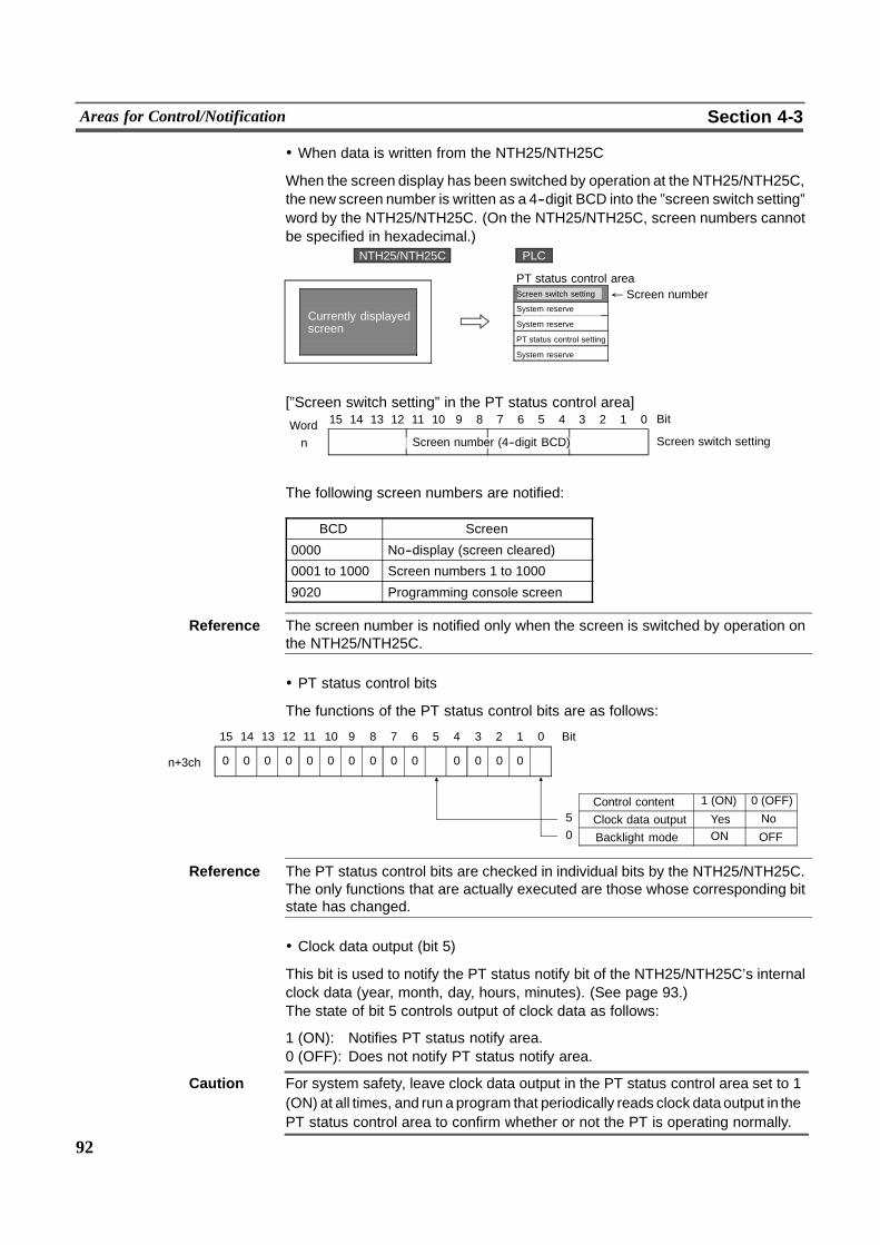
92
Areas for Control/Notification Section 4-3
! When data is written from the NTH25/NTH25C
When the screen display has been switched by operation at the NTH25/NTH25C,the new screen number is written as a 4--digit BCD into the ”screen switch setting”word by the NTH25/NTH25C. (On the NTH25/NTH25C, screen numbers cannotbe specified in hexadecimal.)
Currently displayedscreen
PLCNTH25/NTH25C
" Screen numberPT status control areaScreen switch setting
System reserve
System reserve
PT status control setting
System reserve
[”Screen switch setting” in the PT status control area]15 14 13 12 11 10 9 8 7 6 5 4 3 2 1 0Word Bit
n Screen switch settingScreen number (4--digit BCD)
The following screen numbers are notified:
BCD Screen
0000 No--display (screen cleared)
0001 to 1000 Screen numbers 1 to 1000
9020 Programming console screen
Reference The screen number is notified only when the screen is switched by operation onthe NTH25/NTH25C.
! PT status control bits
The functions of the PT status control bits are as follows:
ON OFF
00
1415 13 12 11 10 9 8 7 Bit
Control content 1 (ON) 0 (OFF)
0
6 5 4 3 2 1 0
0
Clock data output Yes No5
Backlight mode0
00 00000000n+3ch
Reference The PT status control bits are checked in individual bits by the NTH25/NTH25C.The only functions that are actually executed are those whose corresponding bitstate has changed.
! Clock data output (bit 5)
This bit is used to notify the PT status notify bit of the NTH25/NTH25C’s internalclock data (year, month, day, hours, minutes). (See page 93.)The state of bit 5 controls output of clock data as follows:
1 (ON): Notifies PT status notify area.0 (OFF): Does not notify PT status notify area.
Caution For system safety, leave clock data output in the PT status control area set to 1(ON) at all times, and run a program that periodically reads clock dataoutput in thePT status control area to confirm whether or not the PT is operating normally.
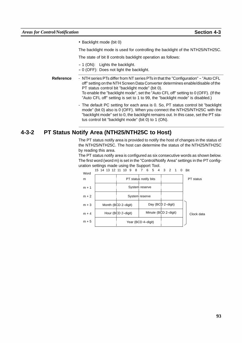
93
Areas for Control/Notification Section 4-3
! Backlight mode (bit 0)
The backlight mode is used for controlling the backlight of the NTH25/NTH25C.
The state of bit 8 controls backlight operation as follows:
-- 1 (ON): Lights the backlight.-- 0 (OFF): Does not light the backlight.
Reference - NTH series PTs differ fromNT series PTs in that the ”Configuration” -- ”Auto CFLoff” setting on theNTHScreenDataConverter determines enable/disable of thePT status control bit ”backlight mode” (bit 0).To enable the ”backlight mode”, set the ”Auto CFL off” setting to 0 (OFF). (If the”Auto CFL off” setting is set to 1 to 99, the ”backlight mode” is disabled.)
- The default PC setting for each area is 0. So, PT status control bit ”backlightmode” (bit 0) also is 0 (OFF). When you connect the NTH25/NTH25C with the”backlight mode” set to 0, the backlight remains out. In this case, set the PT sta-tus control bit ”backlight mode” (bit 0) to 1 (ON).
4-3-2 PT Status Notify Area (NTH25/NTH25C to Host)The PT status notify area is provided to notify the host of changes in the status ofthe NTH25/NTH25C. The host can determine the status of the NTH25/NTH25Cby reading this area.The PT status notify area is configured as six consecutive words as shown below.The first word (wordm) is set in the ”Control/Notify Area” settings in the PT config-uration settings made using the Support Tool.
15 14 13 12 11 10 9 8 7 6 5 4 3 2 1 0Word
Bit
m PT status notify bits PT status
m + 1 System reserve
m + 2
m + 3 Month (BCD 2--digit)
Clock datam + 4 Hour (BCD 2--digit)
System reserve
Year (BCD 4--digit)
Day (BCD 2--digit)
Minute (BCD 2--digit)
m + 5
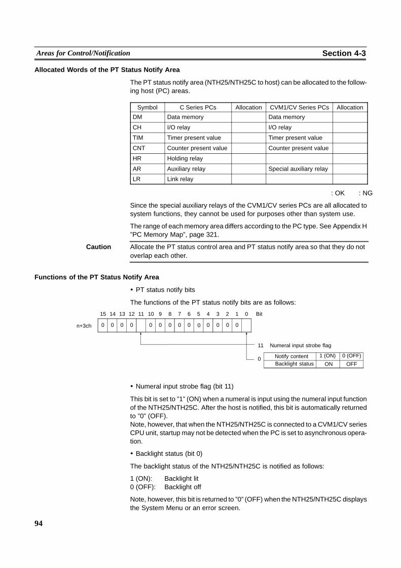
94
Areas for Control/Notification Section 4-3
Allocated Words of the PT Status Notify Area
The PT status notify area (NTH25/NTH25C to host) can be allocated to the follow-ing host (PC) areas.
Symbol C Series PCs Allocation CVM1/CV Series PCs Allocation
DM Data memory � Data memory �CH I/O relay � I/O relay �TIM Timer present value � Timer present value �CNT Counter present value � Counter present value �HR Holding relay � � �AR Auxiliary relay � Special auxiliary relay �LR Link relay � � �
� : OK � : NG
Since the special auxiliary relays of the CVM1/CV series PCs are all allocated tosystem functions, they cannot be used for purposes other than system use.
The range of eachmemory area differs according to the PC type. See Appendix H”PC Memory Map”, page 321.
Caution Allocate the PT status control area and PT status notify area so that they do notoverlap each other.
Functions of the PT Status Notify Area
! PT status notify bits
The functions of the PT status notify bits are as follows:
ON OFF
00
1415 13 12 11 10 9 8 7 Bit
Notify content 1 (ON) 0 (OFF)
0
6 5 4 3 2 1 0
0
11
Backlight status0
00 0000 0000n+3ch
Numeral input strobe flag
! Numeral input strobe flag (bit 11)
This bit is set to ”1” (ON) when a numeral is input using the numeral input functionof the NTH25/NTH25C. After the host is notified, this bit is automatically returnedto ”0” (OFF).Note, however, that when the NTH25/NTH25C is connected to a CVM1/CV seriesCPU unit, startup may not be detected when the PC is set to asynchronous opera-tion.
! Backlight status (bit 0)
The backlight status of the NTH25/NTH25C is notified as follows:
1 (ON): Backlight lit0 (OFF): Backlight off
Note, however, this bit is returned to ”0” (OFF) when the NTH25/NTH25C displaysthe System Menu or an error screen.
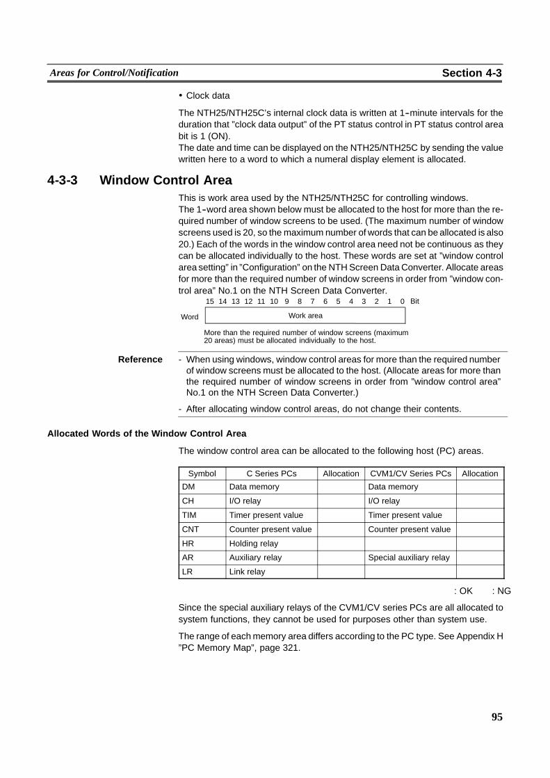
95
Areas for Control/Notification Section 4-3
! Clock data
The NTH25/NTH25C’s internal clock data is written at 1--minute intervals for theduration that ”clock data output” of the PT status control in PT status control areabit is 1 (ON).The date and time can be displayed on the NTH25/NTH25C by sending the valuewritten here to a word to which a numeral display element is allocated.
4-3-3 Window Control AreaThis is work area used by the NTH25/NTH25C for controlling windows.The 1--word area shown below must be allocated to the host for more than the re-quired number of window screens to be used. (The maximum number of windowscreens used is 20, so the maximum number of words that can be allocated is also20.) Each of the words in the window control area need not be continuous as theycan be allocated individually to the host. These words are set at ”window controlarea setting” in ”Configuration” on the NTHScreen DataConverter. Allocate areasfor more than the required number of window screens in order from ”window con-trol area” No.1 on the NTH Screen Data Converter.
15 14 13 12 11 10 9 8 7 6 5 4 3 2 1 0
Word
Bit
More than the required number of window screens (maximum20 areas) must be allocated individually to the host.
Work area
Reference - When using windows, window control areas for more than the required numberof window screens must be allocated to the host. (Allocate areas for more thanthe required number of window screens in order from ”window control area”No.1 on the NTH Screen Data Converter.)
- After allocating window control areas, do not change their contents.
Allocated Words of the Window Control Area
The window control area can be allocated to the following host (PC) areas.
Symbol C Series PCs Allocation CVM1/CV Series PCs Allocation
DM Data memory � Data memory �CH I/O relay � I/O relay �TIM Timer present value � Timer present value �CNT Counter present value � Counter present value �HR Holding relay � � �AR Auxiliary relay � Special auxiliary relay �LR Link relay � � �
� : OK � : NG
Since the special auxiliary relays of the CVM1/CV series PCs are all allocated tosystem functions, they cannot be used for purposes other than system use.
The range of eachmemory area differs according to the PC type. See Appendix H”PC Memory Map”, page 321.
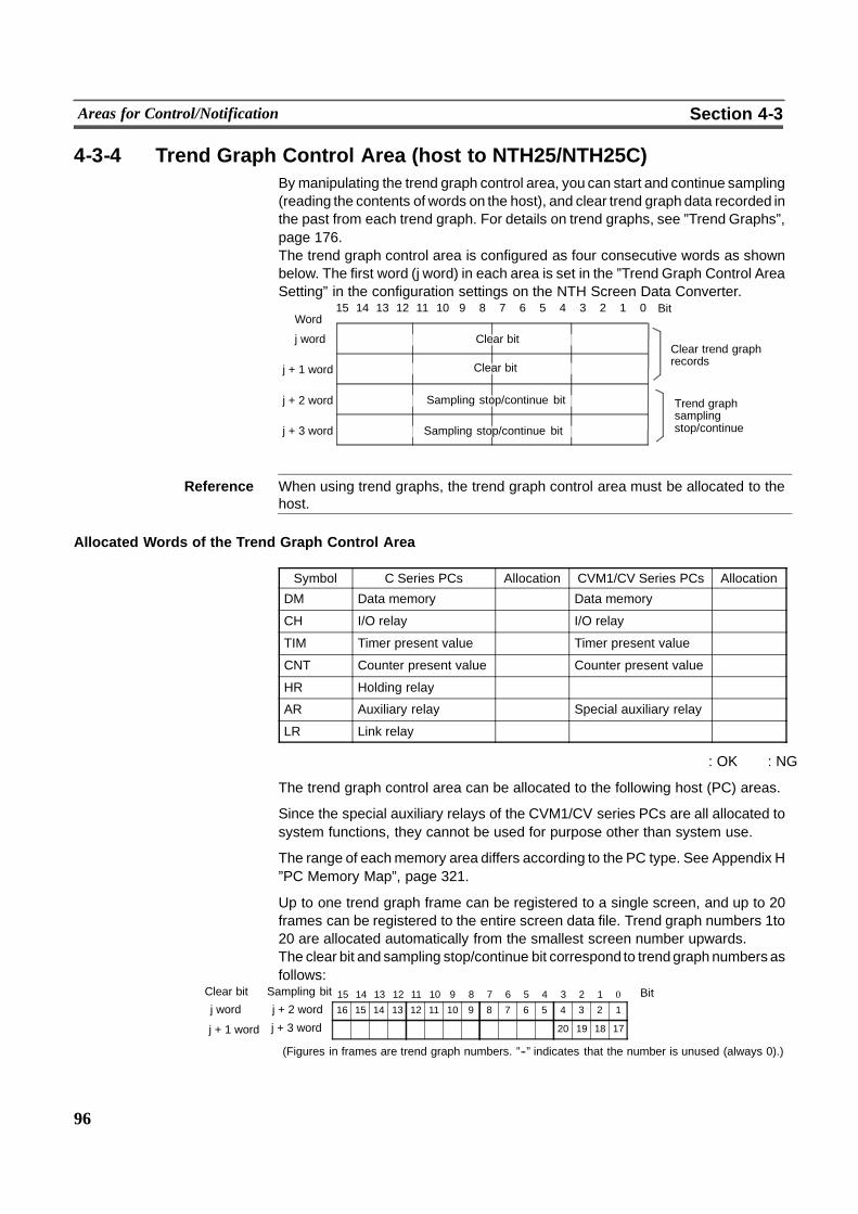
96
Areas for Control/Notification Section 4-3
4-3-4 Trend Graph Control Area (host to NTH25/NTH25C)Bymanipulating the trend graph control area, you can start and continue sampling(reading the contents of words on the host), and clear trend graph data recorded inthe past from each trend graph. For details on trend graphs, see ”Trend Graphs”,page 176.The trend graph control area is configured as four consecutive words as shownbelow. The first word (j word) in each area is set in the ”Trend Graph Control AreaSetting” in the configuration settings on the NTH Screen Data Converter.
15 14 13 12 11 10 9 8 7 6 5 4 3 2 1 0Word
Bit
j word Clear bitClear trend graphrecords
j + 1 word Clear bit
j + 2 word
j + 3 word Sampling stop/continue bit
Trend graphsamplingstop/continue
Sampling stop/continue bit
Reference When using trend graphs, the trend graph control area must be allocated to thehost.
Allocated Words of the Trend Graph Control Area
Symbol C Series PCs Allocation CVM1/CV Series PCs Allocation
DM Data memory � Data memory �CH I/O relay � I/O relay �TIM Timer present value � Timer present value �CNT Counter present value � Counter present value �HR Holding relay � � �AR Auxiliary relay � Special auxiliary relay �LR Link relay � � �
� : OK � : NG
The trend graph control area can be allocated to the following host (PC) areas.
Since the special auxiliary relays of the CVM1/CV series PCs are all allocated tosystem functions, they cannot be used for purpose other than system use.
The range of eachmemory area differs according to the PC type. See Appendix H”PC Memory Map”, page 321.
Up to one trend graph frame can be registered to a single screen, and up to 20frames can be registered to the entire screen data file. Trend graph numbers 1to20 are allocated automatically from the smallest screen number upwards.The clear bit and sampling stop/continue bit correspond to trendgraph numbers asfollows:
16 15 14 13 12 11 10 9 8 7 6 5 4 3 2 1j + 2 word15 14 13 12 11 10 9 8 7 6 5 4 3 2 1 0 Bit
� � � � � � � � � � � � 20 19 18 17j + 3 word
(Figures in frames are trend graph numbers. ”--” indicates that the number is unused (always 0).)
j word
j + 1 word
Sampling bitClear bit

97
Areas for Control/Notification Section 4-3
Functions of the Trend Graph Control Area
Sampling can be stopped and continued, and past data records can be cleared bywriting to each bit corresponding to a trend graph number as follows:
-- Clear bit
0 (OFF): Not cleared1 (ON): Cleared
-- Sampling stop/continue bit
0 (OFF): Continue (not stopped)1 (ON): Stop
Reference Sampling stop/continue and clearing of past records can also be performed by op-erating touch switches. (See page 145.) Note, however, that when a touch switchis operated, the operation is applied collectively to trend graphs 1 to 16 and 17 to20.
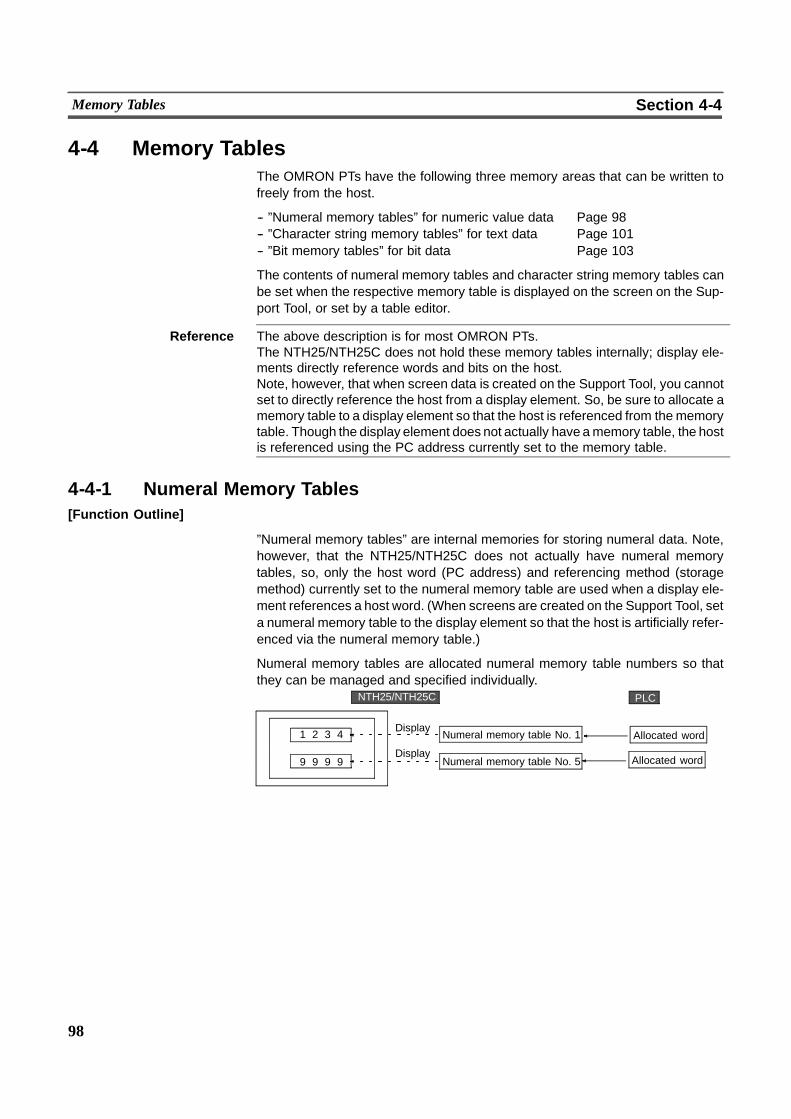
98
Memory Tables Section 4-4
4-4 Memory TablesThe OMRON PTs have the following three memory areas that can be written tofreely from the host.
-- ”Numeral memory tables” for numeric value data Page 98-- ”Character string memory tables” for text data Page 101-- ”Bit memory tables” for bit data Page 103
The contents of numeral memory tables and character string memory tables canbe set when the respective memory table is displayed on the screen on the Sup-port Tool, or set by a table editor.
Reference The above description is for most OMRON PTs.The NTH25/NTH25C does not hold these memory tables internally; display ele-ments directly reference words and bits on the host.Note, however, that when screen data is created on the Support Tool, you cannotset to directly reference the host from a display element. So, be sure to allocate amemory table to a display element so that the host is referenced from thememorytable. Though the display element does not actually have amemory table, the hostis referenced using the PC address currently set to the memory table.
4-4-1 Numeral Memory Tables[Function Outline]
”Numeral memory tables” are internal memories for storing numeral data. Note,however, that the NTH25/NTH25C does not actually have numeral memorytables, so, only the host word (PC address) and referencing method (storagemethod) currently set to the numeral memory table are used when a display ele-ment references a host word. (When screens are created on the Support Tool, seta numeral memory table to the display element so that the host is artificially refer-enced via the numeral memory table.)
Numeral memory tables are allocated numeral memory table numbers so thatthey can be managed and specified individually.
1 2 3 4
9 9 9 9
Display
Display
Numeral memory table No. 1
Numeral memory table No. 5
Allocated word
PLCNTH25/NTH25C
Allocated word

99
Memory Tables Section 4-4
[Setting Restrictions]
The items that can be set on the Support Tool vary from the valid settings on theNTH25/NTH25C. Pay attention to these restrictions when creating screen data.
Item Support Tool NTH25/NTH25C
Number of numeralmemory tables
Changeable Not supported
Number of words in numer-al memory tables
Settable Not supported (Automati-cally determined by thetype of display element andnumber of display digits)
Value Settable Not supported
Initial Settable Not supported
[Common Attributes]
Numeral memory tables have the following properties.
Only sections enclosed by are valid.
Property Possible SettingsPropertyMeaning
Storage Type System/Binary/BCDStorage TypeSets whether to recognize the contents of host words as ”binary”(hexadecimal) or BCD (Binary Codes Decimal).If a setting is made for ”System”, it complies with the ”NumeralStorage Type” setting in the PT configuration.For details, see ”Word contents and displayed numeral” (page163) and ”Input numeral and stored data” (page 208).
PLC Address Any word address on the hostPLC AddressWord on the host to which the numeral memory table is allocatedWhen the numeral memory table is allocated to two words, spec-ify the first (lower) word.For details, see ”Allocated words” (page 100).
I/O Comment Up to 16 characters of textI/O CommentComment that describes the contents of a numeral memory table
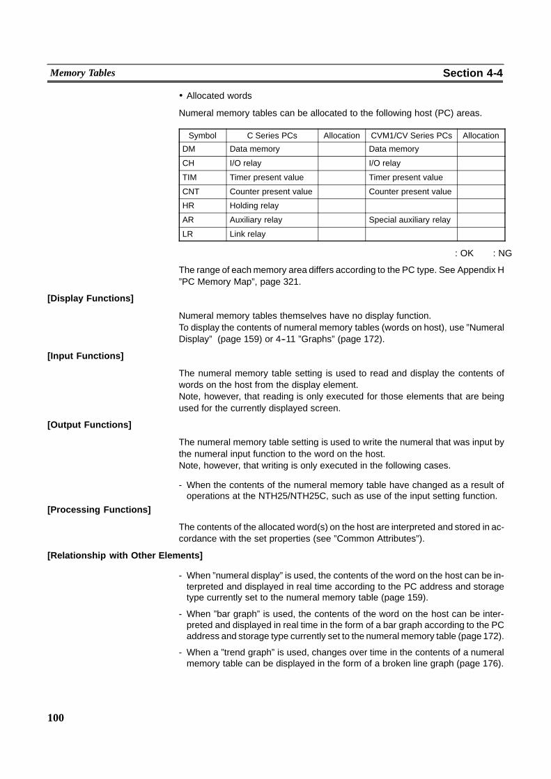
100
Memory Tables Section 4-4
! Allocated words
Numeral memory tables can be allocated to the following host (PC) areas.
Symbol C Series PCs Allocation CVM1/CV Series PCs Allocation
DM Data memory � Data memory �CH I/O relay � I/O relay �TIM Timer present value � Timer present value �CNT Counter present value � Counter present value �HR Holding relay � � �AR Auxiliary relay � Special auxiliary relay �LR Link relay � � �
� : OK � : NG
The range of eachmemory area differs according to the PC type. See Appendix H”PC Memory Map”, page 321.
[Display Functions]
Numeral memory tables themselves have no display function.To display the contents of numeral memory tables (words on host), use ”NumeralDisplay” (page 159) or 4--11 ”Graphs” (page 172).
[Input Functions]
The numeral memory table setting is used to read and display the contents ofwords on the host from the display element.Note, however, that reading is only executed for those elements that are beingused for the currently displayed screen.
[Output Functions]
The numeral memory table setting is used to write the numeral that was input bythe numeral input function to the word on the host.Note, however, that writing is only executed in the following cases.
- When the contents of the numeral memory table have changed as a result ofoperations at the NTH25/NTH25C, such as use of the input setting function.
[Processing Functions]
The contents of the allocated word(s) on the host are interpreted and stored in ac-cordance with the set properties (see ”Common Attributes”).
[Relationship with Other Elements]
- When ”numeral display” is used, the contents of the word on the host can be in-terpreted and displayed in real time according to the PC address and storagetype currently set to the numeral memory table (page 159).
- When ”bar graph” is used, the contents of the word on the host can be inter-preted and displayed in real time in the form of a bar graph according to the PCaddress and storage type currently set to the numeral memory table (page 172).
- When a ”trend graph” is used, changes over time in the contents of a numeralmemory table can be displayed in the form of a broken line graph (page 176).

101
Memory Tables Section 4-4
- When a ”numeral input” is used, numerals can be input to the word on the hostfrom an NTH25/NTH25C screen (page 196).
- If the contents of numeral memory tables are changed by operation on theNTH25/NTH25C, the change is notified to the ”numeral input strobe” of the ”PTstatus notify area” (page 93).
4-4-2 Character String Memory Tables[Function Outline]
”Character string memory tables” are internal memories for recording characterstring data. Note, however, that the NTH25/NTH25C does not actually have char-acter string memory tables, so, only the host word (PC address) currently set tothe character string memory table is used when a character string display elementreferences a host word. (When screens are created on the Support Tool, set acharacter string memory table to the character string display element so that thehost is artificially referenced via the character string memory table.)
Character string memory tables are allocated character string memory table num-bers so that they can be managed and specified individually.
a b c d e
A B C D E
Display
Display
Allocated word
Character string memory table No. 8
Character string memory table No. 12
Read
PLCNTH25/NTH25C
Allocated wordRead
[Setting Restrictions]
The items that can be set on the Support Tool vary from the valid settings on theNTH25/NTH25C. Pay attention to these restrictions when creating screen data.
Item Support Tool NTH25/NTH25C
Number of character stringmemory tables
Settable Not supported
Number of words in char-acter string memory table
Settable Not settable (fixed to 21CH)
Value Used as the initial value ofthe character stringmemory table
Not used as the initial val-ue. It is used only as thealarm message for thealarm list/history function.
Initial Settable Not supported
Usable characters Alphanumerics and sym-bols, marks
Alphanumerics and sym-bols

102
Memory Tables Section 4-4
[Common Attributes]
Character string memory tables have the following properties.
Only sections enclosed by are valid.
Property Possible SettingsPropertyMeaning
Value Alphanumeric and symbolsValueDefault character string after the contents of the character stringmemory table have been initialized. (The default is actually usedas the alarm message for the alarm list/history function.)
PLC Address Any word address on the hostPLC AddressHost word(s) to which the character string memory table is allo-catedSpecify the first (lower) word.For details, see ”Allocated words” below.
I/O Comment Up to 16 characters of textI/O CommentComment that describes the contents of a character stringmemory table
! Allocated words
Character string memory tables can be allocated to the following host (PC) areas.
Symbol C Series PCs Allocation CVM1/CV Series PCs Allocation
DM Data memory � Data memory �CH I/O relay � I/O relay �TIM Timer present value � Timer present value �CNT Counter present value � Counter present value �HR Holding relay � � �AR Auxiliary relay � Special auxiliary relay �LR Link relay � � �
� : OK � : NG
The range of eachmemory area differs according to the PC type. See Appendix H”PC Memory Map”, page 321.
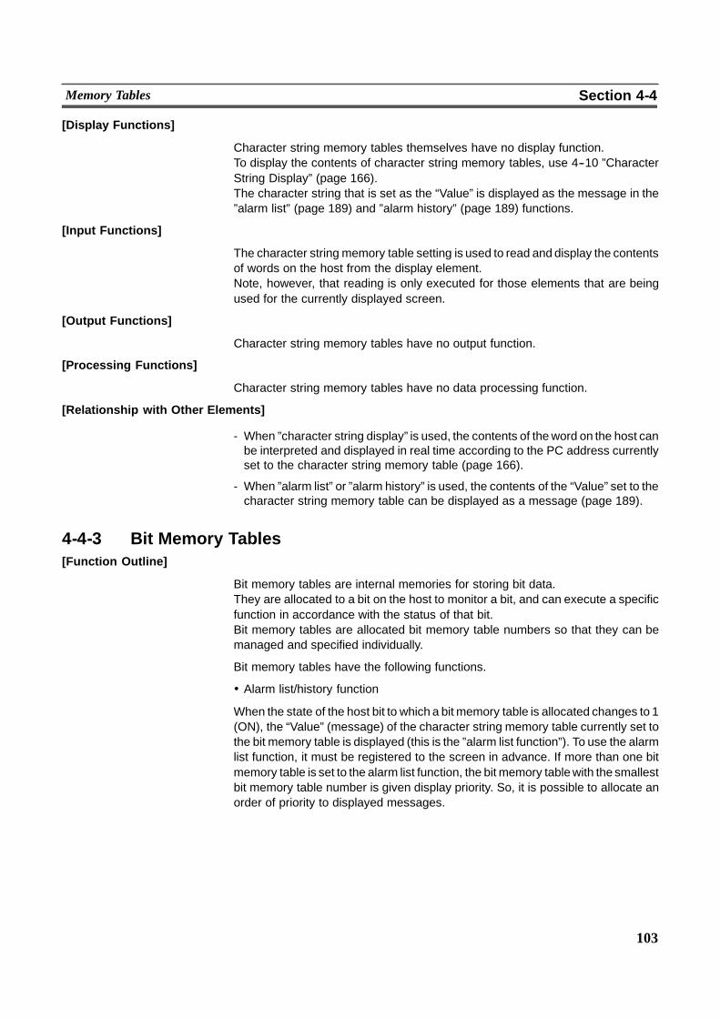
103
Memory Tables Section 4-4
[Display Functions]
Character string memory tables themselves have no display function.To display the contents of character string memory tables, use 4--10 ”CharacterString Display” (page 166).The character string that is set as the “Value” is displayed as the message in the”alarm list” (page 189) and ”alarm history” (page 189) functions.
[Input Functions]
The character string memory table setting is used to read and display the contentsof words on the host from the display element.Note, however, that reading is only executed for those elements that are beingused for the currently displayed screen.
[Output Functions]
Character string memory tables have no output function.
[Processing Functions]
Character string memory tables have no data processing function.
[Relationship with Other Elements]
- When ”character string display” is used, the contents of theword on the host canbe interpreted and displayed in real time according to the PC address currentlyset to the character string memory table (page 166).
- When ”alarm list” or ”alarm history” is used, the contents of the “Value” set to thecharacter string memory table can be displayed as a message (page 189).
4-4-3 Bit Memory Tables[Function Outline]
Bit memory tables are internal memories for storing bit data.They are allocated to a bit on the host to monitor a bit, and can execute a specificfunction in accordance with the status of that bit.Bit memory tables are allocated bit memory table numbers so that they can bemanaged and specified individually.
Bit memory tables have the following functions.
! Alarm list/history function
When the state of the host bit to which a bit memory table is allocated changes to 1(ON), the “Value” (message) of the character string memory table currently set tothe bit memory table is displayed (this is the ”alarm list function”). To use the alarmlist function, it must be registered to the screen in advance. If more than one bitmemory table is set to the alarm list function, the bit memory tablewith the smallestbit memory table number is given display priority. So, it is possible to allocate anorder of priority to displayed messages.
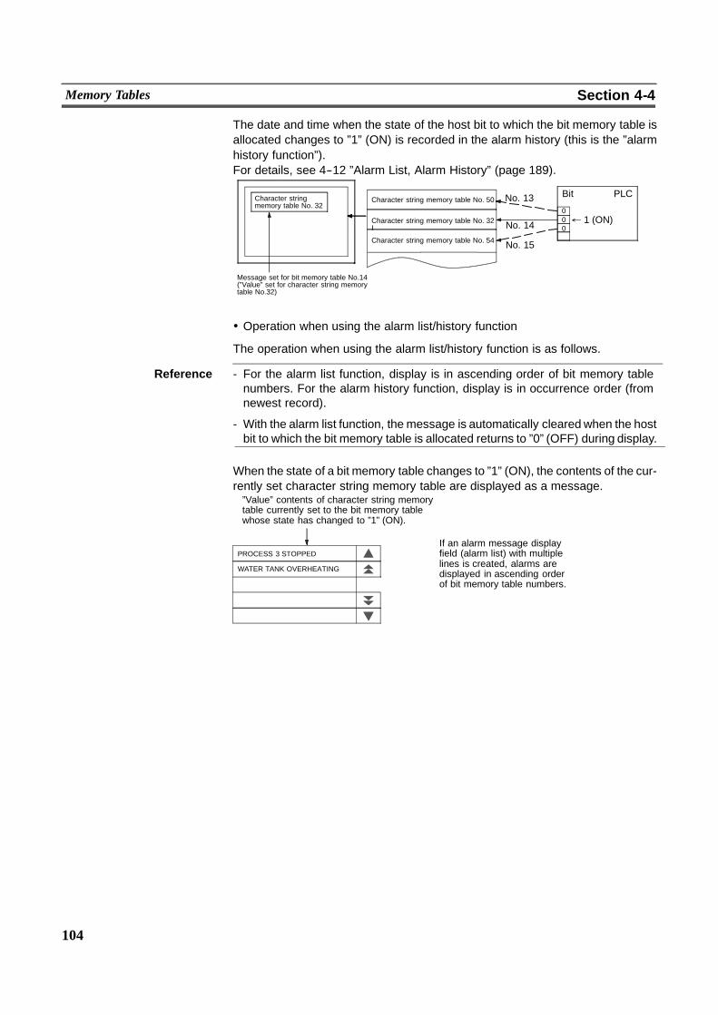
104
Memory Tables Section 4-4
The date and time when the state of the host bit to which the bit memory table isallocated changes to ”1” (ON) is recorded in the alarm history (this is the ”alarmhistory function”).For details, see 4--12 ”Alarm List, Alarm History” (page 189).
Character stringmemory table No. 32
Message set for bit memory table No.14(”Value” set for character string memorytable No.32)
Character string memory table No. 50
Character string memory table No. 32I
Character string memory table No. 54
Bit PLCNo. 13
" 1 (ON)No. 14
No. 15
000
! Operation when using the alarm list/history function
The operation when using the alarm list/history function is as follows.
Reference - For the alarm list function, display is in ascending order of bit memory tablenumbers. For the alarm history function, display is in occurrence order (fromnewest record).
- With the alarm list function, the message is automatically cleared when the hostbit to which the bit memory table is allocated returns to ”0” (OFF) during display.
When the state of a bit memory table changes to ”1” (ON), the contents of the cur-rently set character string memory table are displayed as a message.”Value” contents of character string memorytable currently set to the bit memory tablewhose state has changed to ”1” (ON).
If an alarm message displayfield (alarm list) with multiplelines is created, alarms aredisplayed in ascending orderof bit memory table numbers.
PROCESS 3 STOPPED
WATER TANK OVERHEATING
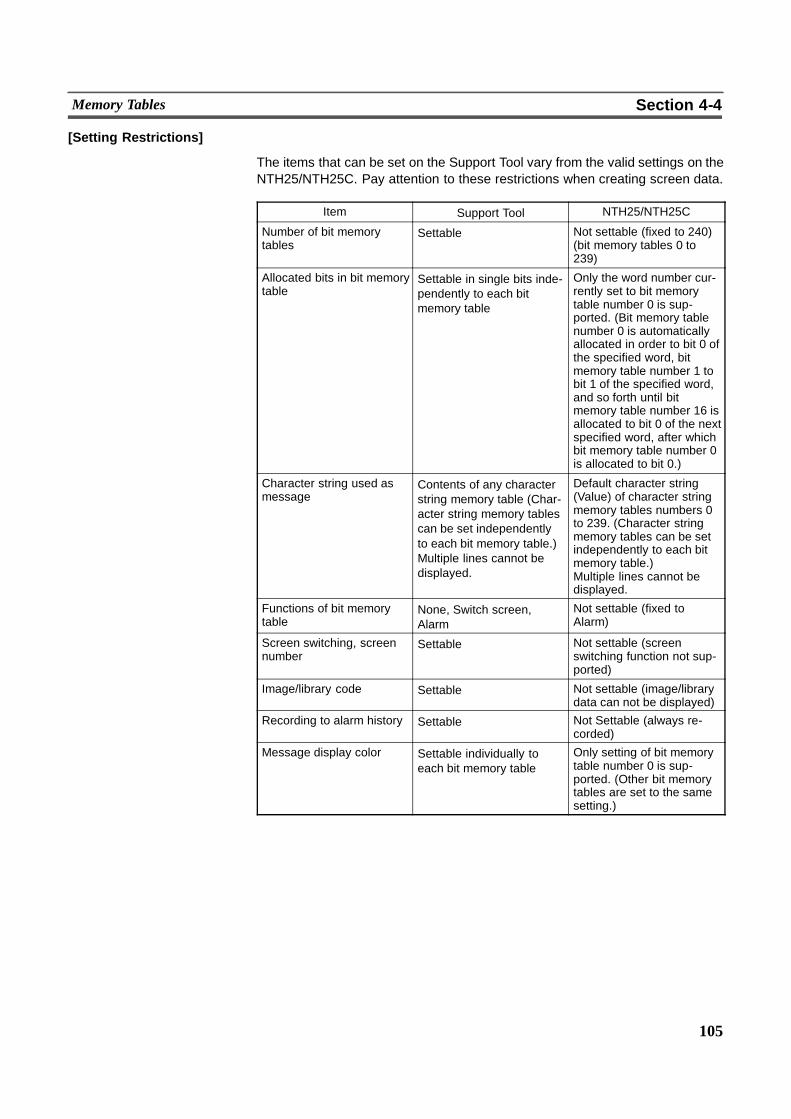
105
Memory Tables Section 4-4
[Setting Restrictions]
The items that can be set on the Support Tool vary from the valid settings on theNTH25/NTH25C. Pay attention to these restrictions when creating screen data.
Item Support Tool NTH25/NTH25C
Number of bit memorytables
Settable Not settable (fixed to 240)(bit memory tables 0 to239)
Allocated bits in bit memorytable
Settable in single bits inde-pendently to each bitmemory table
Only the word number cur-rently set to bit memorytable number 0 is sup-ported. (Bit memory tablenumber 0 is automaticallyallocated in order to bit 0 ofthe specified word, bitmemory table number 1 tobit 1 of the specified word,and so forth until bitmemory table number 16 isallocated to bit 0 of the nextspecified word, after whichbit memory table number 0is allocated to bit 0.)
Character string used asmessage
Contents of any characterstring memory table (Char-acter string memory tablescan be set independentlyto each bit memory table.)Multiple lines cannot bedisplayed.
Default character string(Value) of character stringmemory tables numbers 0to 239. (Character stringmemory tables can be setindependently to each bitmemory table.)Multiple lines cannot bedisplayed.
Functions of bit memorytable
None, Switch screen,Alarm
Not settable (fixed toAlarm)
Screen switching, screennumber
Settable Not settable (screenswitching function not sup-ported)
Image/library code Settable Not settable (image/librarydata can not be displayed)
Recording to alarm history Settable Not Settable (always re-corded)
Message display color Settable individually toeach bit memory table
Only setting of bit memorytable number 0 is sup-ported. (Other bit memorytables are set to the samesetting.)
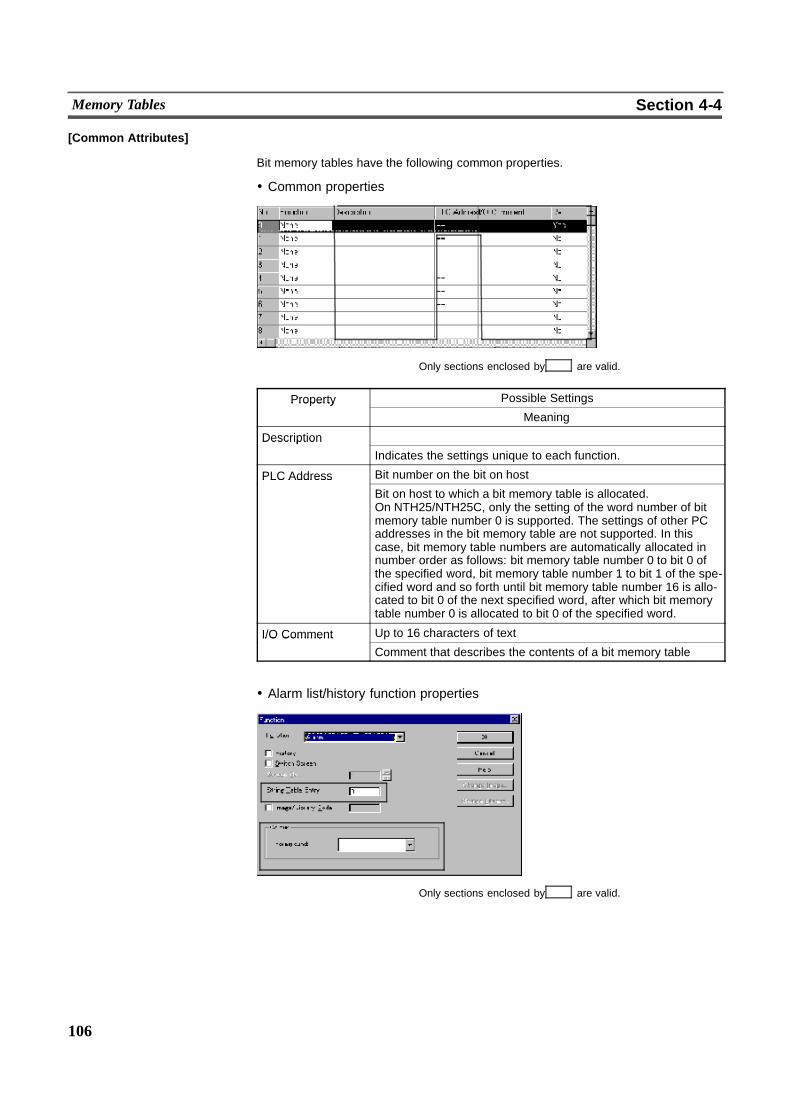
106
Memory Tables Section 4-4
[Common Attributes]
Bit memory tables have the following common properties.
! Common properties
Only sections enclosed by are valid.
Property Possible SettingsPropertyMeaning
DescriptionDescriptionIndicates the settings unique to each function.
PLC Address Bit number on the bit on hostPLC AddressBit on host to which a bit memory table is allocated.On NTH25/NTH25C, only the setting of the word number of bitmemory table number 0 is supported. The settings of other PCaddresses in the bit memory table are not supported. In thiscase, bit memory table numbers are automatically allocated innumber order as follows: bit memory table number 0 to bit 0 ofthe specified word, bit memory table number 1 to bit 1 of the spe-cified word and so forth until bit memory table number 16 is allo-cated to bit 0 of the next specified word, after which bit memorytable number 0 is allocated to bit 0 of the specified word.
I/O Comment Up to 16 characters of textI/O CommentComment that describes the contents of a bit memory table
! Alarm list/history function properties
Only sections enclosed by are valid.
107
Memory Tables Section 4-4
Property Possible SettingsPropertyMeaning
String table entry 0 to 239String table entryNumber of the character string memory table whose contents aredisplayed as a message in the alarm list/history when the state ofthe allocated bit of the bit memory table changes to ”1” (ON).(”Value” set for the character string)
Foreground color Black/Blue/Red/Magenta/Green/Cyan/Yellow/WhiteForeground colorColor of message text (only black and white on NTH25)Only the setting of bit memory number 0 is supported.
! Allocated bit
Bit memory table number 0 can be allocated to the following host (PC) areas. (Onlythe word number is valid. The setting of other allocated bits in the bit memory tableare invalid.)
Symbol C Series PCs Allocation CVM1/CV Series PCs Allocation
DM Data memory � Data memory �CH I/O relay � I/O relay �TIM Timer present value � Timer present value �CNT Counter present value � Counter present value �HR Holding relay � � �AR Auxiliary relay � Special auxiliary relay �LR Link relay � � �
� : OK � : NG
The range of eachmemory area differs according to the PC type. See Appendix H”PC Memory Map”, page 321.
To specify the data memory (DM), a bit number (00 to 15) must be specified aftertheword number. Note, however, that the bit number is always handled as 00 actu-ally.
[Display Functions]
Messages are displayed according to the state of the bit memory table if the ”alarmlist” and ”alarm history” functions are registered to the screen.
[Input Functions]
The contents of bits to which the bit memory table is currently allocated are alwaysread and processed according to the state of the bit memory table. Note, however,that no processing is carried out when a bit is not allocated to bit memory tablenumber 0.
[Output Functions]
Bit memory tables have no output function.
[Processing Functions]
Bit memory tables have no data processing function.
108
Memory Tables Section 4-4
[Relationship with Other Elements]
- When the alarm list function is used, messages can be displayed in real time inaccordance with the state of bits on the host (page 189).
- When the alarm history function is used, the date and time when the state of thehost bit changes to ”1” (ON), and the number of times it comes ON, can be dis-played (page 189).
Reference When the number of alarm history records exceeds 200, the records are deletedfrom the oldest record onwards so that new alarm history data can be stored.
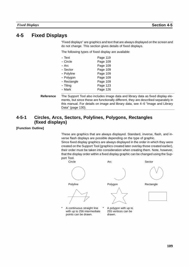
109
Fixed Displays Section 4-5
4-5 Fixed Displays”Fixed displays” are graphics and text that are always displayed on the screen anddo not change. This section gives details of fixed displays.
The following types of fixed display are available:
-- Text Page 119-- Circle Page 109-- Arc Page 109-- Sector Page 109-- Polyline Page 109-- Polygon Page 109-- Rectangle Page 109-- Tiling Page 123-- Mark Page 126
Reference The Support Tool also includes image data and library data as fixed display ele-ments, but since these are functionally different, they are described separately inthis manual. For details on image and library data, see 4--6 ”Image and LibraryData” (page 130).
4-5-1 Circles, Arcs, Sectors, Polylines, Polygons, Rectangles(fixed displays)
[Function Outline]
These are graphics that are always displayed. Standard, inverse, flash, and in-verse flash displays are possible depending on the type of graphic.Since fixed display graphics are always displayed in the order in which they werecreated on the Support Tool (graphics created later overlay those created earlier),their order must be taken into consideration when creating them. Note, however,that the display order within a fixed display graphic can be changed using the Sup-port Tool.
Polyline Polygon Rectangle
Circle SectorArc
* A continuous straight linewith up to 256 intermediatepoints can be drawn.
* A polygon with up to255 vertices can bedrawn.
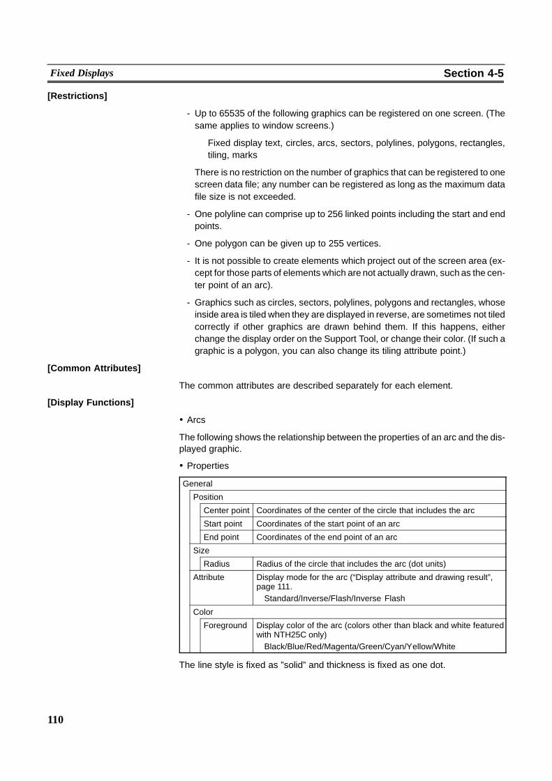
110
Fixed Displays Section 4-5
[Restrictions]
- Up to 65535 of the following graphics can be registered on one screen. (Thesame applies to window screens.)
Fixed display text, circles, arcs, sectors, polylines, polygons, rectangles,tiling, marks
There is no restriction on the number of graphics that can be registered to onescreen data file; any number can be registered as long as the maximum datafile size is not exceeded.
- One polyline can comprise up to 256 linked points including the start and endpoints.
- One polygon can be given up to 255 vertices.
- It is not possible to create elements which project out of the screen area (ex-cept for those parts of elements which are not actually drawn, such as the cen-ter point of an arc).
- Graphics such as circles, sectors, polylines, polygons and rectangles, whoseinside area is tiled when they are displayed in reverse, are sometimes not tiledcorrectly if other graphics are drawn behind them. If this happens, eitherchange the display order on the Support Tool, or change their color. (If such agraphic is a polygon, you can also change its tiling attribute point.)
[Common Attributes]
The common attributes are described separately for each element.
[Display Functions]
! Arcs
The following shows the relationship between the properties of an arc and the dis-played graphic.
! Properties
General
Position
Center point Coordinates of the center of the circle that includes the arc
Start point Coordinates of the start point of an arc
End point Coordinates of the end point of an arc
Size
Radius Radius of the circle that includes the arc (dot units)
Attribute Display mode for the arc (“Display attribute and drawing result”,page 111.Standard/Inverse/Flash/Inverse Flash
Color
Foreground Display color of the arc (colors other than black and white featuredwith NTH25C only)Black/Blue/Red/Magenta/Green/Cyan/Yellow/White
The line style is fixed as ”solid” and thickness is fixed as one dot.

111
Fixed Displays Section 4-5
On the Support Tool, specify the center point, start point and end point as follows.When the start point is set, the radius is automatically set accordingly.
Start point
Center point
End point
Radius
! Display attribute and drawing result
Attribute Drawing Result
Standard Only the line of the arc is drawn in the foreground color.
Inverse*1 The arc drawn between its start and end points isdisplayed in the foreground inverse color.
Inverse color display
Flash Repeated alternation between ”standard” display and nodisplay.
& No display
Inverse Flash*1 Repeated alternation between ”inverse” and no display.
& No display
Inverse color display
*1 If the arc’s background color is set to the same color as the inverse color of ”linecolor”, the arc will become invisible. Change either ”line color” or the back-ground color.
! Circle
The following shows the relationship between the properties of a circle and the dis-played graphic.

112
Fixed Displays Section 4-5
! Properties
General
Position
Center point Coordinates of the center of the circle
Size
Radius Radius of the circle (dot units)
Attribute Display mode for the circle (“Display attribute and drawing result”,below).Standard/Inverse/Flash/Inverse Flash
Color
Foreground Display color of the circle (colors other than black and whitefeatured with NTH25C only)Black/Blue/Red/Magenta/Green/Cyan/Yellow/White
The line style is fixed as ”solid” and thickness is fixed as one dot.
On the Support Tool, specify the center point and radius as follows.
Center pointRadius
! Display attribute and drawing result
Attribute Drawing Result
Standard Only the line of the circle periphery is drawn in theforeground color.
Inverse*1 The entire circle is displayed in the foreground inversecolor.
Flash Repeated alternation between ”standard” display and nodisplay.
& No display
Inverse Flash*1 Repeated alternation between ”inverse” and no display.
& No display
*1 If the circle’s background color is set to the same color as the inverse color of”foreground color”, the circle will become invisible. Change either ”foregroundcolor” or the background color.
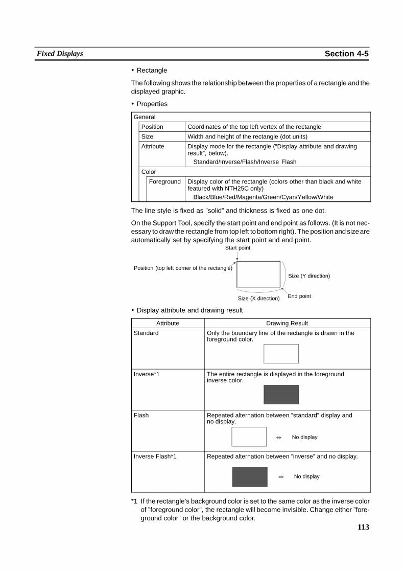
113
Fixed Displays Section 4-5
! Rectangle
The following shows the relationship between the properties of a rectangle and thedisplayed graphic.
! Properties
General
Position Coordinates of the top left vertex of the rectangle
Size Width and height of the rectangle (dot units)
Attribute Display mode for the rectangle (“Display attribute and drawingresult”, below).Standard/Inverse/Flash/Inverse Flash
Color
Foreground Display color of the rectangle (colors other than black and whitefeatured with NTH25C only)Black/Blue/Red/Magenta/Green/Cyan/Yellow/White
The line style is fixed as ”solid” and thickness is fixed as one dot.
On the Support Tool, specify the start point and end point as follows. (It is not nec-essary to draw the rectangle from top left to bottom right). The positionand sizeareautomatically set by specifying the start point and end point.
Start point
Position (top left corner of the rectangle)Size (Y direction)
Size (X direction) End point
! Display attribute and drawing result
Attribute Drawing Result
Standard Only the boundary line of the rectangle is drawn in theforeground color.
Inverse*1 The entire rectangle is displayed in the foregroundinverse color.
Flash Repeated alternation between ”standard” display andno display.
& No display
Inverse Flash*1 Repeated alternation between ”inverse” and no display.
& No display
*1 If the rectangle’s background color is set to the same color as the inverse colorof ”foreground color”, the rectangle will become invisible. Change either ”fore-ground color” or the background color.
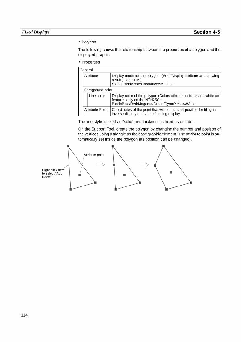
114
Fixed Displays Section 4-5
! Polygon
The following shows the relationship between the properties of a polygon and thedisplayed graphic.
! Properties
General
Attribute Display mode for the polygon. (See ”Display attribute and drawingresult”, page 115.)Standard/Inverse/Flash/Inverse Flash
Foreground color
Line color Display color of the polygon (Colors other than black and white arefeatures only on the NTH25C.)Black/Blue/Red/Magenta/Green/Cyan/Yellow/White
Attribute Point Coordinates of the point that will be the start position for tiling ininverse display or inverse flashing display.
The line style is fixed as ”solid” and thickness is fixed as one dot.
On the Support Tool, create the polygon by changing the number and position ofthe vertices using a triangle as the base graphic element. The attribute point is au-tomatically set inside the polygon (its position can be changed).
Attribute point
Right click hereto select “AddNode”.
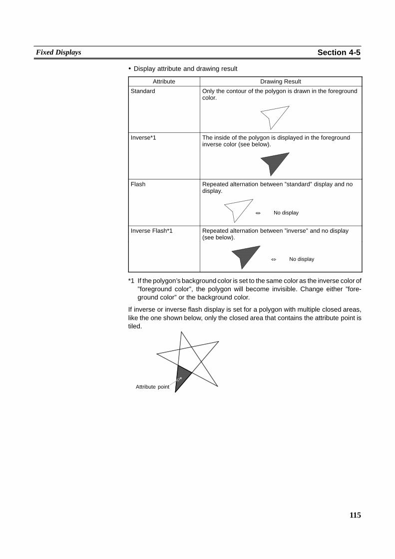
115
Fixed Displays Section 4-5
! Display attribute and drawing result
Attribute Drawing Result
Standard Only the contour of the polygon is drawn in the foregroundcolor.
Inverse*1 The inside of the polygon is displayed in the foregroundinverse color (see below).
Flash Repeated alternation between ”standard” display and nodisplay.
& No display
Inverse Flash*1 Repeated alternation between ”inverse” and no display(see below).
& No display
*1 If the polygon’s background color is set to the same color as the inverse color of”foreground color”, the polygon will become invisible. Change either ”fore-ground color” or the background color.
If inverse or inverse flash display is set for a polygon with multiple closed areas,like the one shown below, only the closed area that contains the attribute point istiled.
Attribute point
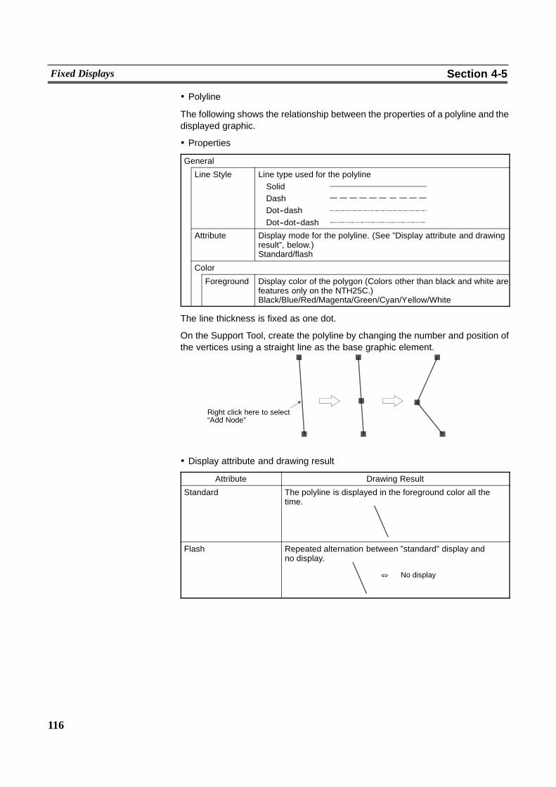
116
Fixed Displays Section 4-5
! Polyline
The following shows the relationship between the properties of a polyline and thedisplayed graphic.
! Properties
General
Line Style Line type used for the polylineSolidDashDot--dashDot--dot--dash
Attribute Display mode for the polyline. (See ”Display attribute and drawingresult”, below.)Standard/flash
Color
Foreground Display color of the polygon (Colors other than black and white arefeatures only on the NTH25C.)Black/Blue/Red/Magenta/Green/Cyan/Yellow/White
The line thickness is fixed as one dot.
On the Support Tool, create the polyline by changing the number and position ofthe vertices using a straight line as the base graphic element.
Right click here to select“Add Node”
! Display attribute and drawing result
Attribute Drawing Result
Standard The polyline is displayed in the foreground color all thetime.
Flash Repeated alternation between ”standard” display andno display.
& No display
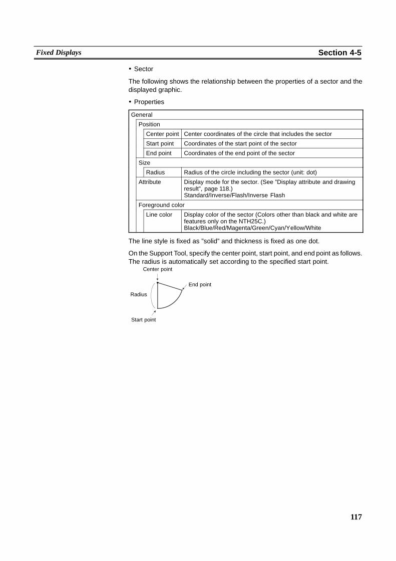
117
Fixed Displays Section 4-5
! Sector
The following shows the relationship between the properties of a sector and thedisplayed graphic.
! Properties
General
Position
Center point Center coordinates of the circle that includes the sector
Start point Coordinates of the start point of the sector
End point Coordinates of the end point of the sector
Size
Radius Radius of the circle including the sector (unit: dot)
Attribute Display mode for the sector. (See ”Display attribute and drawingresult”, page 118.)Standard/Inverse/Flash/Inverse Flash
Foreground color
Line color Display color of the sector (Colors other than black and white arefeatures only on the NTH25C.)Black/Blue/Red/Magenta/Green/Cyan/Yellow/White
The line style is fixed as ”solid” and thickness is fixed as one dot.
On the Support Tool, specify the center point, start point, and end point as follows.The radius is automatically set according to the specified start point.
End point
Center point
Start point
Radius
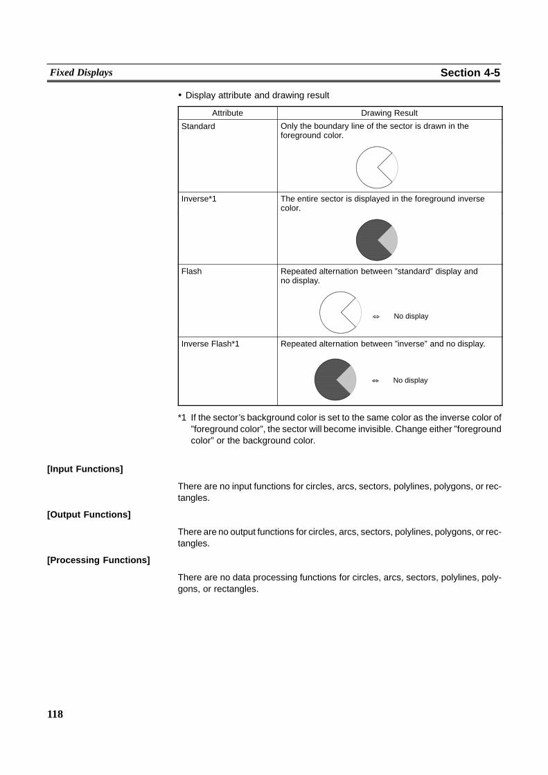
118
Fixed Displays Section 4-5
! Display attribute and drawing result
Attribute Drawing Result
Standard Only the boundary line of the sector is drawn in theforeground color.
Inverse*1 The entire sector is displayed in the foreground inversecolor.
Flash Repeated alternation between ”standard” display andno display.
& No display
Inverse Flash*1 Repeated alternation between ”inverse” and no display.
& No display
*1 If the sector’s background color is set to the same color as the inverse color of”foreground color”, the sector will become invisible. Change either ”foregroundcolor” or the background color.
[Input Functions]
There are no input functions for circles, arcs, sectors, polylines, polygons, or rec-tangles.
[Output Functions]
There are no output functions for circles, arcs, sectors, polylines, polygons, or rec-tangles.
[Processing Functions]
There are no data processing functions for circles, arcs, sectors, polylines, poly-gons, or rectangles.
119
Fixed Displays Section 4-5
[Relationship with Other Elements]
- When tiling is used, the inside of an area enclosed by a continuous solid line ofthe same color can be tiled with a specified pattern (page 123). Note, however,that if the line is broken at any point, or if it flashes or is deleted, the tiling pat-tern will project and cover the area outside the line as well. Tiling will alsospread outside the intended boundary line, in accordance with the display or-der, if it is displayed before the boundary line.
- It is possible to groupmultiple fixed display elements as a single library data bycombining multiple fixed display elements. If the display attribute for any of theelements when you are registering the element is ”Flash” or ”Inverse Flash”,the display flashes in accordance with this setting. The timing of the flashing isthe same for all elements.
- Both text (page 119) andmark (page 126) fixed displays will overlap each oth-er in accordance with the order in which they were created. Note, however,that you can change the way in which they overlap using the Support Tool.
4-5-2 Text (Fixed Display)[Function Outline]
These are character strings that are continually displayed as a fixed display. Stan-dard, flash, and inverse flash displays are possible. (Inverse display can be speci-fied by swapping the foreground color and background color of the characterstring.)Since the display order will always follow the order in which the elements arecreated on the Support Tool (character strings created later overlay others createdearlier), the order in which text is created must be taken into consideration whencharacter strings are going to overlap.On the NTH25/NTH25C, character strings are not allowed to contain marks (char-acter code FF20 to FFFF Hex). (Marks are treated as invalid codes and are dis-played as two standard characters.)
NTH25C[Restrictions]
- Up to 65535 of the following graphics can be registered on one screen. (Thesame applies to window screens.)
Fixed display text, circles, arcs, sectors, polylines, polygons, rectangles,tiling, marks
There is no restriction on the number of graphics that can be registered toone screen data file; any number can be registered as long as the maxi-mum data file size is not exceeded.
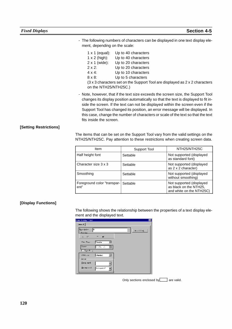
120
Fixed Displays Section 4-5
- The following numbers of characters can be displayed in one text display ele-ment, depending on the scale:
1 x 1 (equal): Up to 40 characters1 x 2 (high): Up to 40 characters2 x 1 (wide): Up to 20 characters2 x 2: Up to 20 characters4 x 4: Up to 10 characters8 x 8: Up to 5 characters(3 x 3 characters set on the Support Tool are displayed as 2 x 2 characterson the NTH25/NTH25C.)
- Note, however, that if the text size exceeds the screen size, the Support Toolchanges its display position automatically so that the text is displayed to fit in-side the screen. If the text can not be displayed within the screen even if theSupport Tool has changed its position, an error message will be displayed. Inthis case, change the number of characters or scale of the text so that the textfits inside the screen.
[Setting Restrictions]
The items that can be set on the Support Tool vary from the valid settings on theNTH25/NTH25C. Pay attention to these restrictions when creating screen data.
Item Support Tool NTH25/NTH25C
Half height font Settable Not supported (displayedas standard font)
Character size 3 x 3 Settable Not supported (displayedas 2 x 2 character)
Smoothing Settable Not supported (displayedwithout smoothing)
Foreground color ”transpar-ent”
Settable Not supported (displayedas black on the NTH25,and white on the NTH25C)
[Display Functions]
The following shows the relationship between the properties of a text display ele-ment and the displayed text.
Only sections enclosed by are valid.
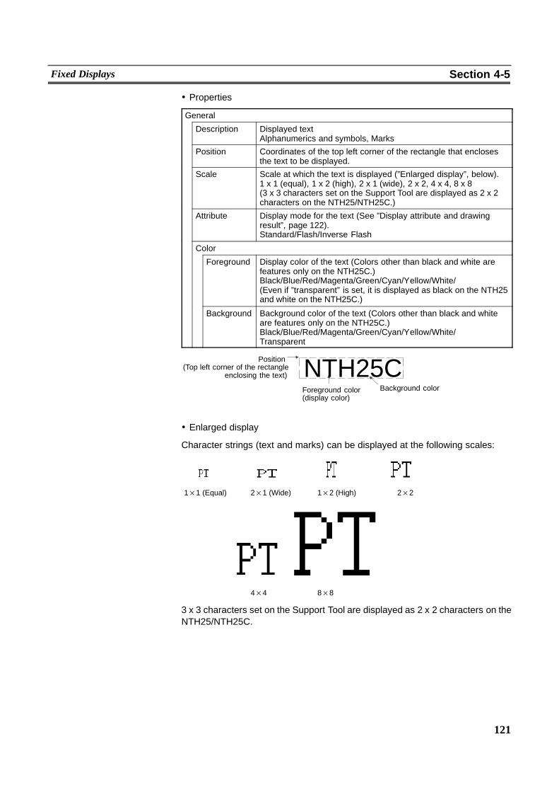
121
Fixed Displays Section 4-5
! Properties
General
Description Displayed textAlphanumerics and symbols, Marks
Position Coordinates of the top left corner of the rectangle that enclosesthe text to be displayed.
Scale Scale at which the text is displayed (”Enlarged display”, below).1 x 1 (equal), 1 x 2 (high), 2 x 1 (wide), 2 x 2, 4 x 4, 8 x 8(3 x 3 characters set on the Support Tool are displayed as 2 x 2characters on the NTH25/NTH25C.)
Attribute Display mode for the text (See ”Display attribute and drawingresult”, page 122).Standard/Flash/Inverse Flash
Color
Foreground Display color of the text (Colors other than black and white arefeatures only on the NTH25C.)Black/Blue/Red/Magenta/Green/Cyan/Yellow/White/(Even if ”transparent” is set, it is displayed as black on the NTH25and white on the NTH25C.)
Background Background color of the text (Colors other than black and whiteare features only on the NTH25C.)Black/Blue/Red/Magenta/Green/Cyan/Yellow/White/Transparent
NTH25CPosition(Top left corner of the rectangle
enclosing the text)
Foreground color(display color)
Background color
! Enlarged display
Character strings (text and marks) can be displayed at the following scales:
1×1 (Equal) 2×1 (Wide) 1×2 (High) 2×2
4×4 8×8
3 x 3 characters set on the Support Tool are displayed as 2 x 2 characters on theNTH25/NTH25C.
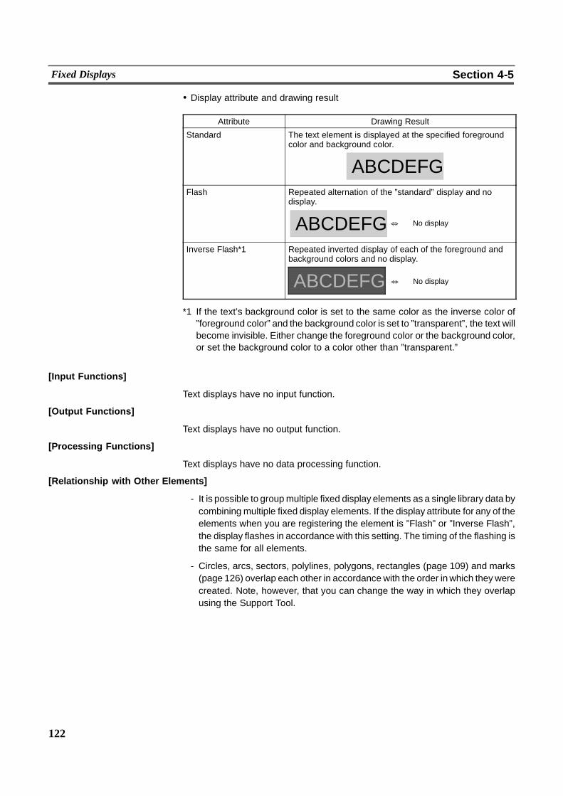
122
Fixed Displays Section 4-5
! Display attribute and drawing result
Attribute Drawing Result
Standard The text element is displayed at the specified foregroundcolor and background color.
ABCDEFGFlash Repeated alternation of the ”standard” display and no
display.
ABCDEFG & No display
Inverse Flash*1 Repeated inverted display of each of the foreground andbackground colors and no display.
ABCDEFG & No display
*1 If the text’s background color is set to the same color as the inverse color of”foreground color” and the background color is set to ”transparent”, the text willbecome invisible. Either change the foreground color or the background color,or set the background color to a color other than ”transparent.”
[Input Functions]
Text displays have no input function.
[Output Functions]
Text displays have no output function.
[Processing Functions]
Text displays have no data processing function.
[Relationship with Other Elements]
- It is possible to groupmultiple fixed display elements as a single library data bycombining multiple fixed display elements. If the display attribute for any of theelements when you are registering the element is ”Flash” or ”Inverse Flash”,the display flashes in accordance with this setting. The timing of the flashing isthe same for all elements.
- Circles, arcs, sectors, polylines, polygons, rectangles (page 109) and marks(page 126) overlap each other in accordance with the order inwhich they werecreated. Note, however, that you can change the way in which they overlapusing the Support Tool.
123
Fixed Displays Section 4-5
4-5-3 Tiling[Function Outline]
An area enclosed by a solid line of a specified color is tiled with the specified tilingpattern.
[Restrictions]
- Up to 65535 of the following graphics can be registered on one screen. (Thesame applies to window screens.)
Fixed display text, circles, arcs, sectors, polylines, polygons, rectangles,tiling, marks
There is no restriction on the number of graphics that can be registered to onescreen data file; any number can be registered as long as the maximum datafile size is not exceeded.
- The area to be tiledmust be enclosed by a solid lineof the same color. If the lineis broken at any point, or if it flashes or is deleted, the tiling pattern will projectand cover the area outside the line as well. Tiling will also spread outside theintended boundary line, in accordance with the display order, if it is displayedbefore the border line.
- Depending on the combination of the foreground color (wheb tiled) and thebackground color of a graphic, part of the frame of the graphicmay be invisible.This is a phenomenon peculiar to a color LCD, not a failure of the PT. If thiscauses a problem, change the color combination.The line thickness of images on the Support Tool differs from that on theNTH25/NTH25C. Be sure to check the display on the NTH25/NTH25C.
[Setting Restrictions]
The items that can be set on the Support Tool vary from the valid settings on theNTH25/NTH25C. Pay attention to these restrictions when creating screen data.
Item Support Tool NTH25/NTH25C
Border Settable Not settable (”Foregroundcolor” is used as bordercolor.)
Tiling pattern ”Box,” ”Grid”and ”border”
Settable Not supported (Displays”Uniform”.)
Tiling pattern ”Slant right”and ”Slant left”
� The foreground color be-comes the background col-or, and vice versa.
Background color ”trans-parent”
Settable Not settable (displayed asblack on NTH25 and whiteon the NTH25C)
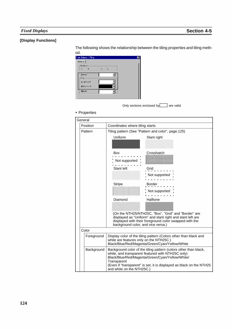
124
Fixed Displays Section 4-5
[Display Functions]
The following shows the relationship between the tiling properties and tiling meth-od.
Only sections enclosed by are valid.
! Properties
General
Position Coordinates where tiling starts
Pattern Tiling pattern (See ”Pattern and color”, page.125)
Uniform Slant right
Box Crosshatch
Slant left Grid
Stripe Border
Diamond Halftone
Not supported
Not supported
Not supported
(On the NTH25/NTH25C, ”Box”, ”Grid” and ”Border” aredisplayed as ”Uniform” and slant right and slant left aredisplayed with their foreground color swapped with thebackground color, and vice versa.)
Color
Foreground Display color of the tiling pattern (Colors other than black andwhite are features only on the NTH25C.)Black/Blue/Red/Magenta/Green/Cyan/Yellow/White
Background Background color of the tiling pattern (colors other than black,white, and transparent featured with NTH25C only)Black/Blue/Red/Magenta/Green/Cyan/Yellow/White/Transparent(Even if ”transparent” is set, it is displayed as black on the NTH25and white on the NTH25C.)
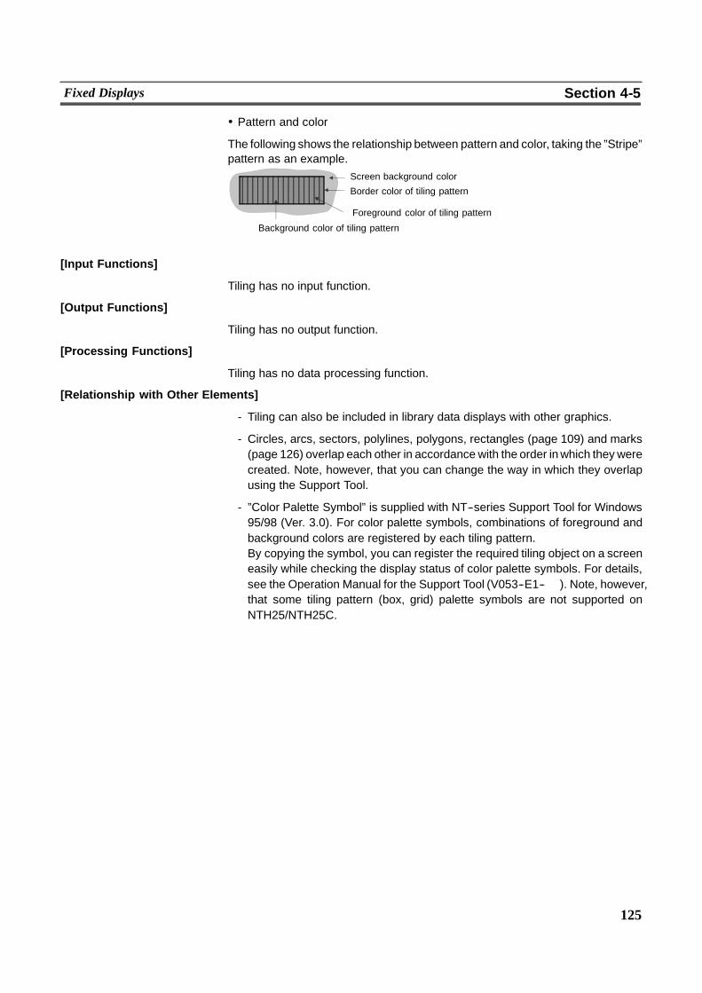
125
Fixed Displays Section 4-5
! Pattern and color
The following shows the relationship between pattern and color, taking the ”Stripe”pattern as an example.
Screen background color
Border color of tiling pattern
Foreground color of tiling pattern
Background color of tiling pattern
[Input Functions]
Tiling has no input function.
[Output Functions]
Tiling has no output function.
[Processing Functions]
Tiling has no data processing function.
[Relationship with Other Elements]
- Tiling can also be included in library data displays with other graphics.
- Circles, arcs, sectors, polylines, polygons, rectangles (page 109) and marks(page 126) overlap each other in accordance with the order inwhich they werecreated. Note, however, that you can change the way in which they overlapusing the Support Tool.
- ”Color Palette Symbol” is supplied with NT--series Support Tool for Windows95/98 (Ver. 3.0). For color palette symbols, combinations of foreground andbackground colors are registered by each tiling pattern.By copying the symbol, you can register the required tiling object on a screeneasily while checking the display status of color palette symbols. For details,see the Operation Manual for the Support Tool (V053--E1--� ). Note, however,that some tiling pattern (box, grid) palette symbols are not supported onNTH25/NTH25C.

126
Fixed Displays Section 4-5
4-5-4 Marks[Function Outline]
Marks are pictograms comprising 16 by 16 dots. They are allocated to charactercodes for use.Marks are created with the mark editor on the Support Tool, independently ofscreens, and asmany as required can be displayed at any position on any screen.
! Procedure for creating and using marks
The following briefly describes the procedure for creating marks and registeringthem on a screen. For details, see the Operation Manual for the Support Tool.
Call the mark editor.
Specify the mark code.
Create the mark.
Exit the mark editor and register the mark.
Perform screen editing.
Register the created mark for display.
'
'
'
'
'
[Restrictions]
- Up to 83 marks can be created for one screen data file. Each of the marks isallocated any required character code within the range FF20 to FF72 Hex sothat it can bemanaged and specified. Though any code up to FFFFHex canberegistered on the Support Tool, do not use FF73 Hex onwards as these codesare reserved for the system.
- Up to 65535 of the following graphics can be registered on one screen. (Thesame applies to window screens.)
Fixed display text, circles, arcs, sectors, polylines, polygons, rectangles,tiling, marks
There is no restriction on the number of graphics that can be registered to onescreen data file; any number can be registered as long as the maximum datafile size is not exceeded.
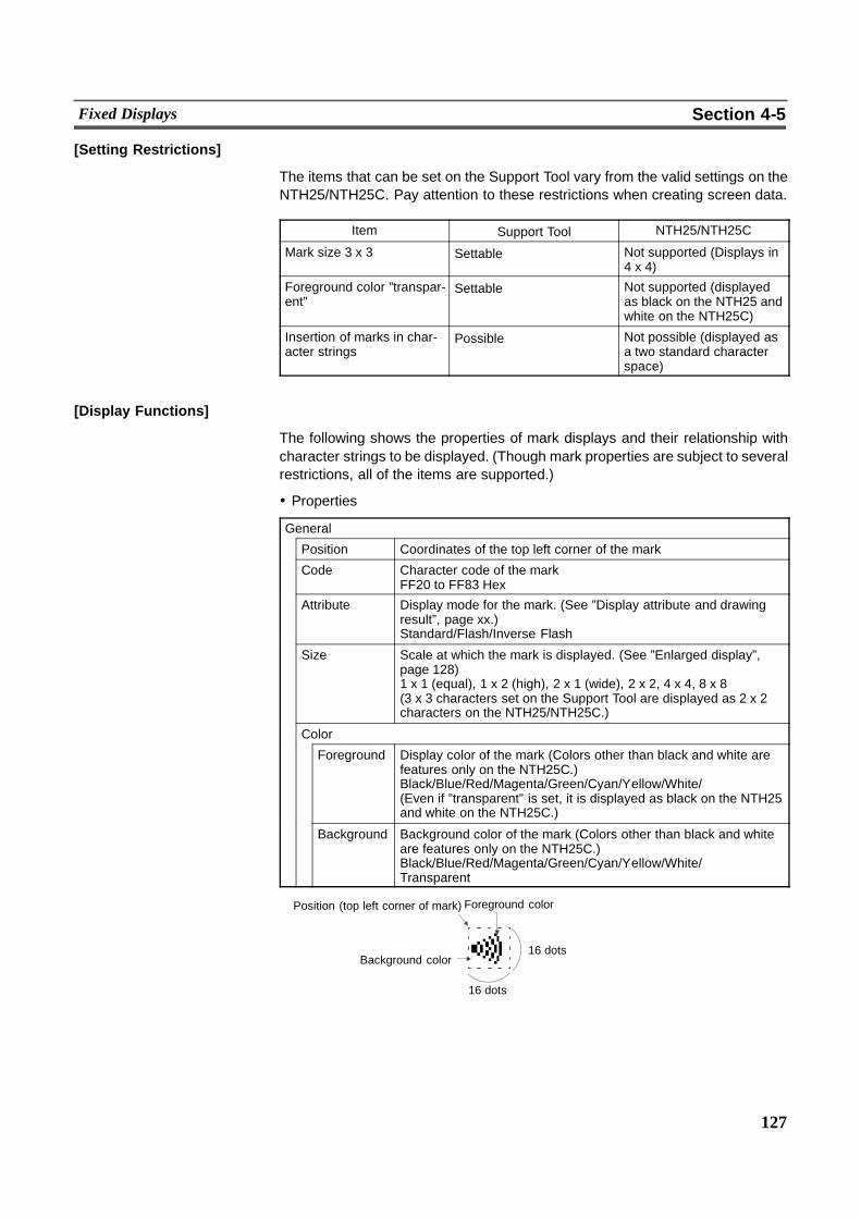
127
Fixed Displays Section 4-5
[Setting Restrictions]
The items that can be set on the Support Tool vary from the valid settings on theNTH25/NTH25C. Pay attention to these restrictions when creating screen data.
Item Support Tool NTH25/NTH25C
Mark size 3 x 3 Settable Not supported (Displays in4 x 4)
Foreground color ”transpar-ent”
Settable Not supported (displayedas black on the NTH25 andwhite on the NTH25C)
Insertion of marks in char-acter strings
Possible Not possible (displayed asa two standard characterspace)
[Display Functions]
The following shows the properties of mark displays and their relationship withcharacter strings to be displayed. (Though mark properties are subject to severalrestrictions, all of the items are supported.)
! Properties
General
Position Coordinates of the top left corner of the mark
Code Character code of the markFF20 to FF83 Hex
Attribute Display mode for the mark. (See ”Display attribute and drawingresult”, page xx.)Standard/Flash/Inverse Flash
Size Scale at which the mark is displayed. (See ”Enlarged display”,page 128)1 x 1 (equal), 1 x 2 (high), 2 x 1 (wide), 2 x 2, 4 x 4, 8 x 8(3 x 3 characters set on the Support Tool are displayed as 2 x 2characters on the NTH25/NTH25C.)
Color
Foreground Display color of the mark (Colors other than black and white arefeatures only on the NTH25C.)Black/Blue/Red/Magenta/Green/Cyan/Yellow/White/(Even if ”transparent” is set, it is displayed as black on the NTH25and white on the NTH25C.)
Background Background color of the mark (Colors other than black and whiteare features only on the NTH25C.)Black/Blue/Red/Magenta/Green/Cyan/Yellow/White/Transparent
16 dots
Position (top left corner of mark) Foreground color
Background color
16 dots
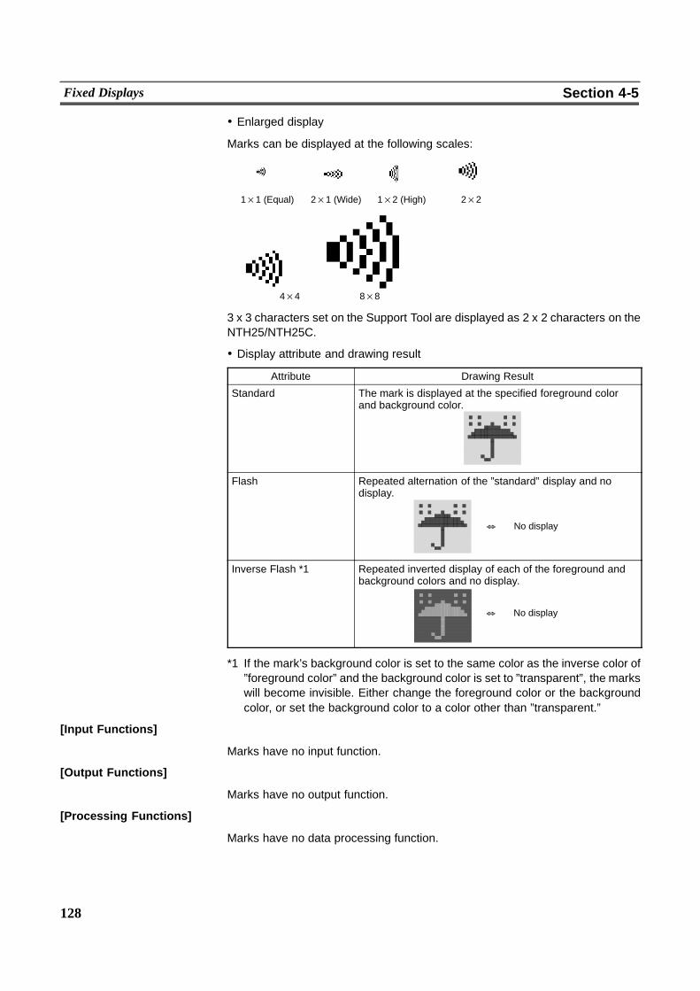
128
Fixed Displays Section 4-5
! Enlarged display
Marks can be displayed at the following scales:
1×1 (Equal) 2×1 (Wide) 1×2 (High) 2×2
4×4 8×8
3 x 3 characters set on the Support Tool are displayed as 2 x 2 characters on theNTH25/NTH25C.
! Display attribute and drawing result
Attribute Drawing Result
Standard The mark is displayed at the specified foreground colorand background color.
Flash Repeated alternation of the ”standard” display and nodisplay.
& No display
Inverse Flash *1 Repeated inverted display of each of the foreground andbackground colors and no display.
& No display
*1 If the mark’s background color is set to the same color as the inverse color of”foreground color” and the background color is set to ”transparent”, the markswill become invisible. Either change the foreground color or the backgroundcolor, or set the background color to a color other than ”transparent.”
[Input Functions]
Marks have no input function.
[Output Functions]
Marks have no output function.
[Processing Functions]
Marks have no data processing function.

129
Fixed Displays Section 4-5
[Relationship with Other Elements]
- It is possible to groupmultiple fixed display elements as a single library data bycombining multiple fixed display elements. If the display attribute for any of theelements when you are registering the element is ”Flash” or ”Inverse Flash”,the display flashes in accordance with this setting. The timing of the flashing isthe same for all elements.
- Marks overlap with other fixed display elements in accordance with the orderin which they were registered. Note, however, that you can change the way inwhich they overlap using the Support Tool.
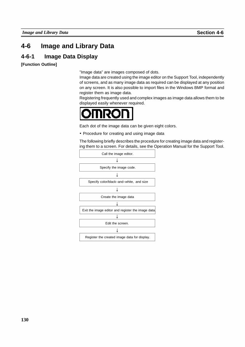
130
Image and Library Data Section 4-6
4-6 Image and Library Data
4-6-1 Image Data Display[Function Outline]
”Image data” are images composed of dots.Image data are created using the image editor on the Support Tool, independentlyof screens, and as many image data as required can be displayed at any positionon any screen. It is also possible to import files in the Windows BMP format andregister them as image data.Registering frequently used and complex images as image data allows them to bedisplayed easily whenever required.
Each dot of the image data can be given eight colors.
! Procedure for creating and using image data
The following briefly describes the procedure for creating image data and register-ing them to a screen. For details, see the Operation Manual for the Support Tool.
'
'
'
'
'
'
Call the image editor.
Specify the image code.
Specify color/black--and--white, and size
Create the image data
Exit the image editor and register the image data.
Edit the screen.
Register the created image data for display.
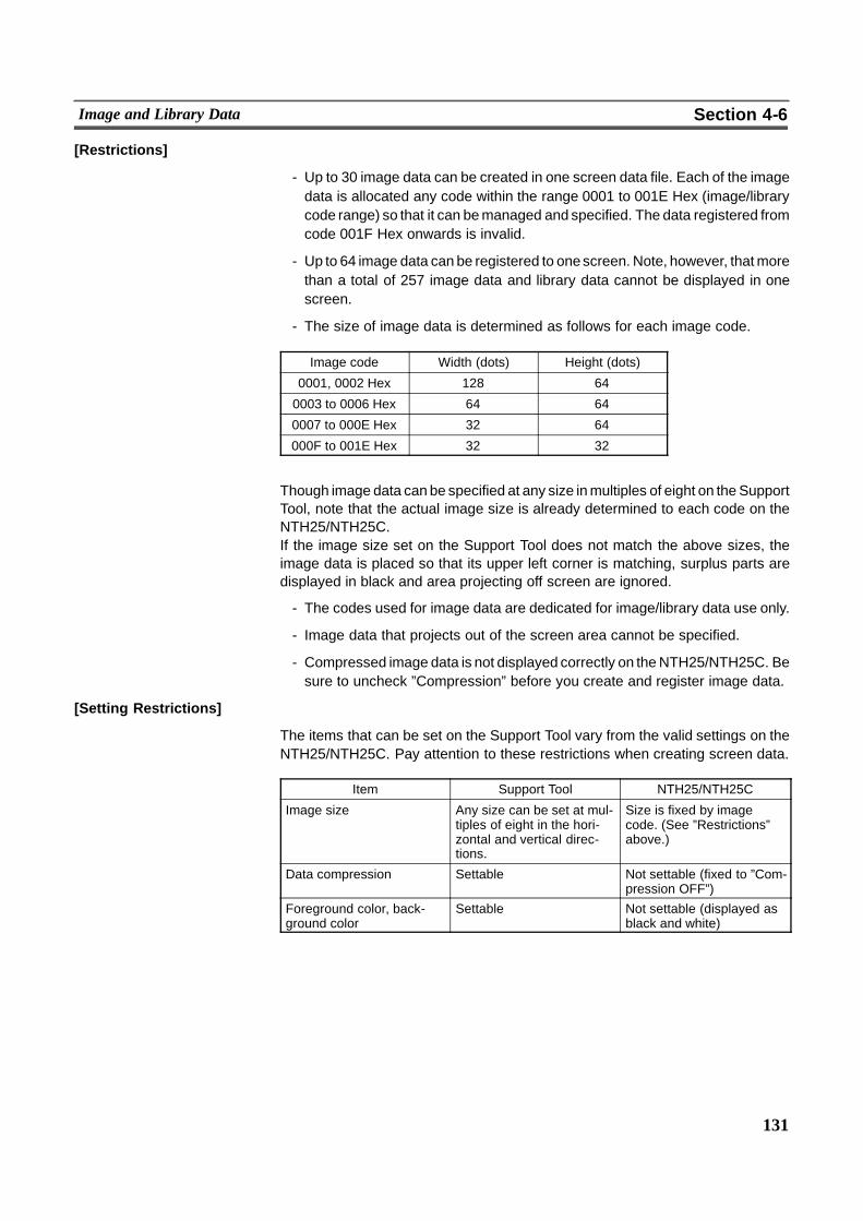
131
Image and Library Data Section 4-6
[Restrictions]
- Up to 30 image data can be created in one screen data file. Each of the imagedata is allocated any code within the range 0001 to 001E Hex (image/librarycode range) so that it can bemanaged and specified. The data registered fromcode 001F Hex onwards is invalid.
- Up to 64 image data can be registered to onescreen. Note, however, thatmorethan a total of 257 image data and library data cannot be displayed in onescreen.
- The size of image data is determined as follows for each image code.
Image code Width (dots) Height (dots)
0001, 0002 Hex 128 64
0003 to 0006 Hex 64 64
0007 to 000E Hex 32 64
000F to 001E Hex 32 32
Though image data can be specified at any size inmultiples of eight on the SupportTool, note that the actual image size is already determined to each code on theNTH25/NTH25C.If the image size set on the Support Tool does not match the above sizes, theimage data is placed so that its upper left corner is matching, surplus parts aredisplayed in black and area projecting off screen are ignored.
- The codes used for image data are dedicated for image/library data use only.
- Image data that projects out of the screen area cannot be specified.
- Compressed image data is not displayed correctly on theNTH25/NTH25C. Besure to uncheck ”Compression” before you create and register image data.
[Setting Restrictions]
The items that can be set on the Support Tool vary from the valid settings on theNTH25/NTH25C. Pay attention to these restrictions when creating screen data.
Item Support Tool NTH25/NTH25C
Image size Any size can be set at mul-tiples of eight in the hori-zontal and vertical direc-tions.
Size is fixed by imagecode. (See ”Restrictions”above.)
Data compression Settable Not settable (fixed to ”Com-pression OFF”)
Foreground color, back-ground color
Settable Not settable (displayed asblack and white)
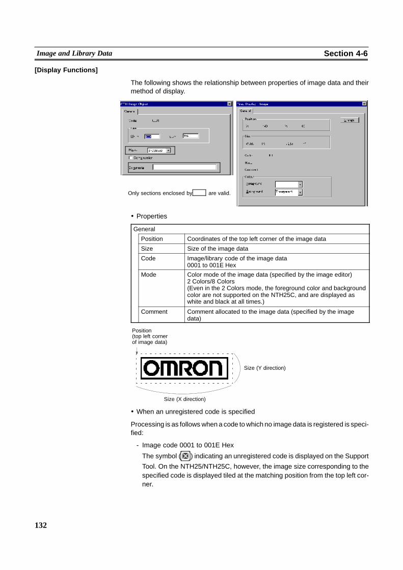
132
Image and Library Data Section 4-6
[Display Functions]
The following shows the relationship between properties of image data and theirmethod of display.
Only sections enclosed by are valid.
! Properties
General
Position Coordinates of the top left corner of the image data
Size Size of the image data
Code Image/library code of the image data0001 to 001E Hex
Mode Color mode of the image data (specified by the image editor)2 Colors/8 Colors(Even in the 2 Colors mode, the foreground color and backgroundcolor are not supported on the NTH25C, and are displayed aswhite and black at all times.)
Comment Comment allocated to the image data (specified by the imagedata)
Position(top left cornerof image data)
Size (Y direction)
Size (X direction)
! When an unregistered code is specified
Processing is as followswhena code towhich no image data is registered is speci-fied:
- Image code 0001 to 001E Hex
The symbol ( ) indicating an unregistered code is displayed on the Support
Tool. On the NTH25/NTH25C, however, the image size corresponding to thespecified code is displayed tiled at the matching position from the top left cor-ner.
133
Image and Library Data Section 4-6
- Image code 001F to 0FFF Hex
The symbol ( ) indicating an unregistered code is displayed on the Support
Tool, but on the NTH25/NTH25C nothing is displayed.
[Input Functions]
Image data have no input function.
[Output Functions]
Image data have no output function.
[Processing Functions]
Image data have no data processing function.
[Relationship with Other Elements]
- Difference between image data and library dataImage data can take any form as it is composed of dots, but library data canonly be formed by combining fixed display--text or graphics.Since only drawing information for text and graphics is registered as the librarydata, library data is lighter than image data, which requires all the dots to bedisplayed on the screen to be registered as data.Another difference is that ”flash” and ”inverse flash” display are not possible forimage data, whereas library data can be displayed in these display modes inaccordancewith the display attributes of the registered elements. All elementsflash at the same time.
- it is possible to specify different image/library data for the graphic displayedwhen a lamp (image/library lamp) is ON and OFF (page 137).
- Image data elements overlap with other fixed display elements in accordancewith the order in which they were registered. Note, however, that you canchange the way in which they overlap using the Support Tool.
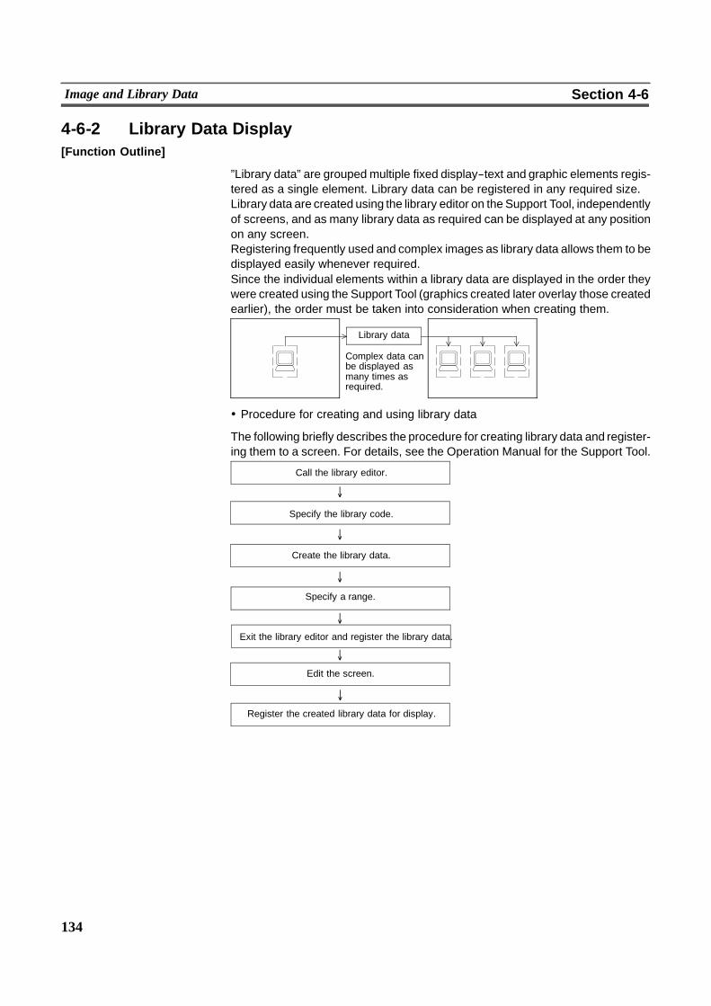
134
Image and Library Data Section 4-6
4-6-2 Library Data Display[Function Outline]
”Library data” are grouped multiple fixed display--text and graphic elements regis-tered as a single element. Library data can be registered in any required size.Library data are created using the library editor on the Support Tool, independentlyof screens, and as many library data as required can be displayed at any positionon any screen.Registering frequently used and complex images as library data allows them to bedisplayed easily whenever required.Since the individual elements within a library data are displayed in the order theywere created using the Support Tool (graphics created later overlay those createdearlier), the order must be taken into consideration when creating them.
Complex data canbe displayed asmany times asrequired.
Library data
! Procedure for creating and using library data
The following briefly describes the procedure for creating library data and register-ing them to a screen. For details, see the Operation Manual for the Support Tool.
'
'
'
'
'
'
Call the library editor.
Specify the library code.
Create the library data.
Specify a range.
Exit the library editor and register the library data.
Edit the screen.
Register the created library data for display.
135
Image and Library Data Section 4-6
Reference When creating lamps on the NTH25C (color type) screen using the NT--seriesSupport Tool (Ver 3.0), pay attention to the following.
- When the ”background color” screen property is set to a color other than black,the light ON and OFF colors of the lamp are not displayed correctly.To correctly light the lamp, either tile a fixed graphic of the same size as the lampand place it so that it overlaps the lamp, or use regular tiling without using the”background color” screen property.
[Restrictions]
- Up to 3980 library data can be created in one screen data file. Each of the li-brary data is allocated any code within the range 1000 to 1F8B Hex (image/li-brary code range) so that it can be managed and specified.
- A total of up to 256 of library data can be registered to one screen. Note, how-ever, that more than a total of 257 image data and library data cannot be dis-played in one screen.
- Themaximum number of elements that can be registered to one library data is64.
- The following fixed display elements can be registered in library data. Otherelements cannot be registered.
Text, circles, arcs, sectors, polylines, polygons, rectangles, tiling, marks
- The codes used for library data are dedicated for image/library data use only.
- It is not possible to create library data which project out of the screen area.
[Setting Restrictions]
The items that can be set on the Support Tool vary from the valid settings on theNTH25/NTH25C. Pay attention to these restrictions when creating screen data.
Item Support Tool NTH25/NTH25C
Maximum number of librarydata
12288 3980
Library code 1000 to 3FFF Hex 1000 to 1F8B Hex
[Display Functions]
The following shows the relationship between properties of library data and their method ofdisplay. (Though library data properties are subject to several restrictions, all of the itemsaresupported.)
! Properties
General
Position Coordinates of the top left corner of the library data
Size Size of the library data
Code Image/library code of the library data1000 to 1F8B Hex
Comment Comment allocated to the library data(specified by the library editor)
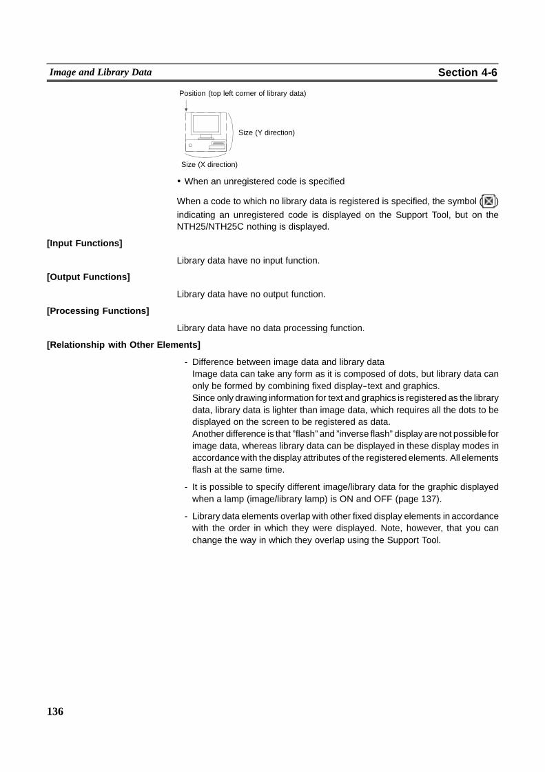
136
Image and Library Data Section 4-6
Size (X direction)
Position (top left corner of library data)
Size (Y direction)
! When an unregistered code is specified
When a code to which no library data is registered is specified, the symbol ( )indicating an unregistered code is displayed on the Support Tool, but on theNTH25/NTH25C nothing is displayed.
[Input Functions]
Library data have no input function.
[Output Functions]
Library data have no output function.
[Processing Functions]
Library data have no data processing function.
[Relationship with Other Elements]
- Difference between image data and library dataImage data can take any form as it is composed of dots, but library data canonly be formed by combining fixed display--text and graphics.Since only drawing information for text and graphics is registered as the librarydata, library data is lighter than image data, which requires all the dots to bedisplayed on the screen to be registered as data.Another difference is that ”flash” and ”inverse flash” display are not possible forimage data, whereas library data can be displayed in these display modes inaccordancewith the display attributes of the registered elements. All elementsflash at the same time.
- It is possible to specify different image/library data for the graphic displayedwhen a lamp (image/library lamp) is ON and OFF (page 137).
- Library data elements overlap with other fixed display elements in accordancewith the order in which they were displayed. Note, however, that you canchange the way in which they overlap using the Support Tool.
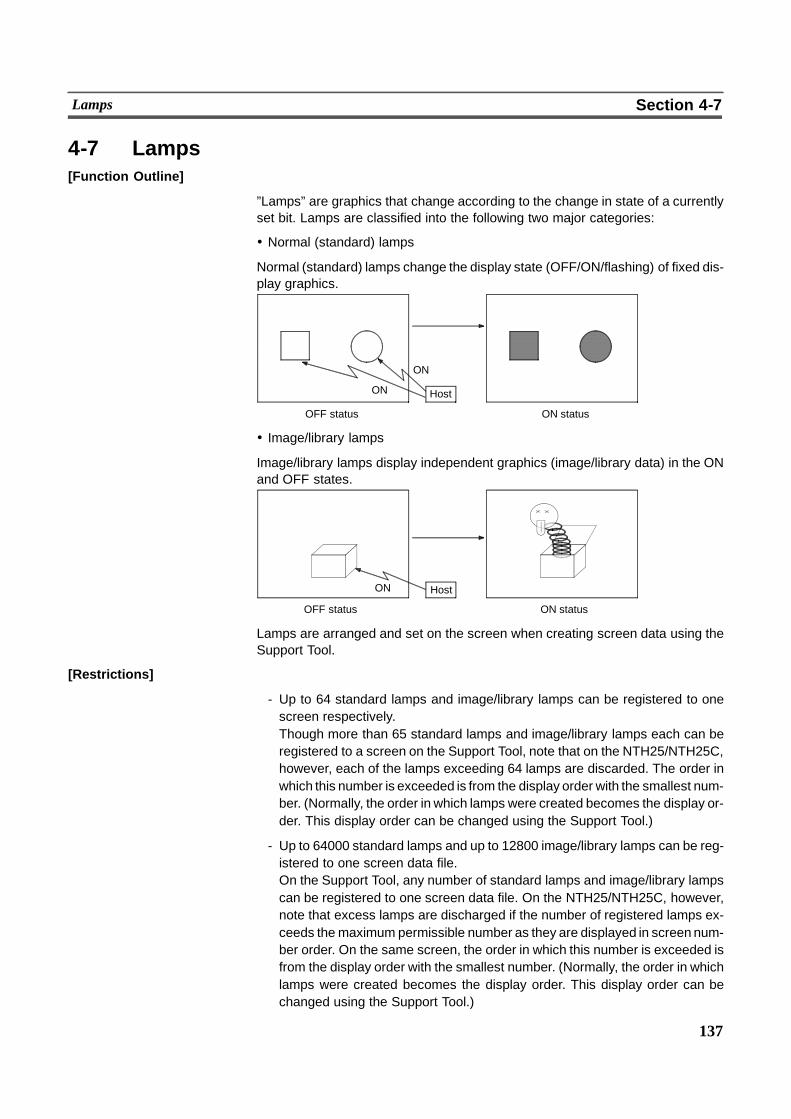
137
Lamps Section 4-7
4-7 Lamps[Function Outline]
”Lamps” are graphics that change according to the change in state of a currentlyset bit. Lamps are classified into the following two major categories:
! Normal (standard) lamps
Normal (standard) lamps change the display state (OFF/ON/flashing) of fixed dis-play graphics.
ON
ON
ON status
Host
OFF status
! Image/library lamps
Image/library lamps display independent graphics (image/library data) in the ONand OFF states.
ON status
Host
OFF status
ON
Lamps are arranged and set on the screen when creating screen data using theSupport Tool.
[Restrictions]
- Up to 64 standard lamps and image/library lamps can be registered to onescreen respectively.Though more than 65 standard lamps and image/library lamps each can beregistered to a screen on the Support Tool, note that on the NTH25/NTH25C,however, each of the lamps exceeding 64 lamps are discarded. The order inwhich this number is exceeded is from the display order with the smallest num-ber. (Normally, the order in which lamps were created becomes the display or-der. This display order can be changed using the Support Tool.)
- Up to 64000 standard lamps and up to 12800 image/library lamps can be reg-istered to one screen data file.On the Support Tool, any number of standard lamps and image/library lampscan be registered to one screen data file. On the NTH25/NTH25C, however,note that excess lamps are discharged if the number of registered lamps ex-ceeds the maximum permissible number as they are displayed in screen num-ber order. On the same screen, the order in which this number is exceeded isfrom the display order with the smallest number. (Normally, the order in whichlamps were created becomes the display order. This display order can bechanged using the Support Tool.)
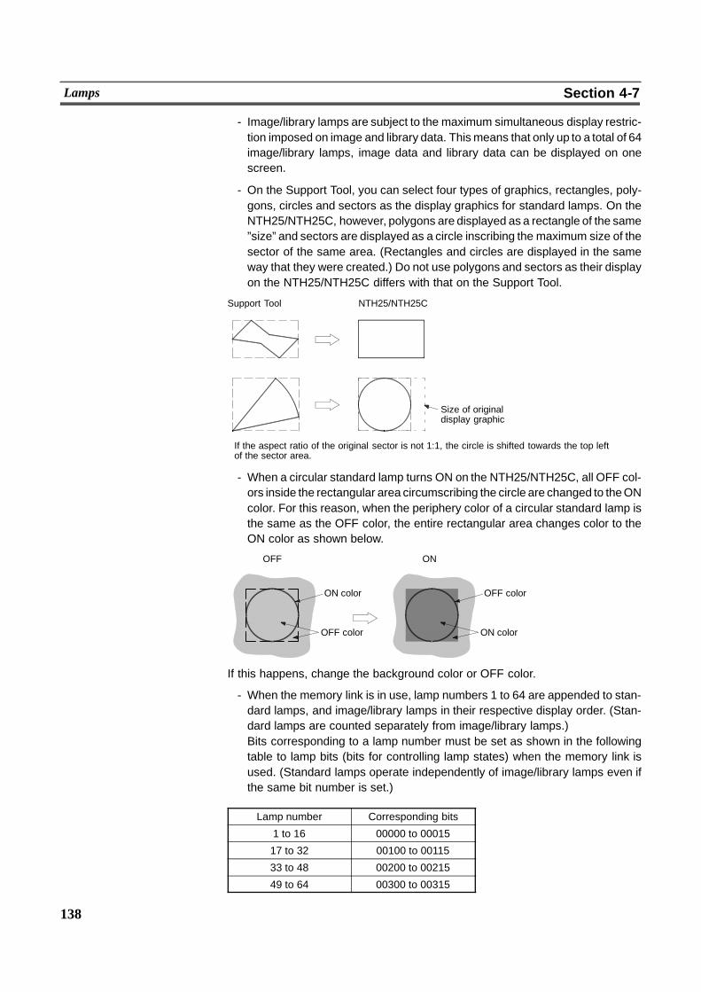
138
Lamps Section 4-7
- Image/library lamps are subject to the maximum simultaneous display restric-tion imposed on image and library data. Thismeans that only up to a total of 64image/library lamps, image data and library data can be displayed on onescreen.
- On the Support Tool, you can select four types of graphics, rectangles, poly-gons, circles and sectors as the display graphics for standard lamps. On theNTH25/NTH25C, however, polygons are displayed as a rectangle of the same”size” and sectors are displayed as a circle inscribing the maximum size of thesector of the same area. (Rectangles and circles are displayed in the sameway that they were created.) Do not use polygons and sectors as their displayon the NTH25/NTH25C differs with that on the Support Tool.
Support Tool NTH25/NTH25C
Size of originaldisplay graphic
If the aspect ratio of the original sector is not 1:1, the circle is shifted towards the top leftof the sector area.
- When a circular standard lamp turns ON on the NTH25/NTH25C, all OFF col-ors inside the rectangular area circumscribing the circle are changed to theONcolor. For this reason, when the periphery color of a circular standard lamp isthe same as the OFF color, the entire rectangular area changes color to theON color as shown below.
ON
ON color
OFF color
OFF
OFF color
ON color
If this happens, change the background color or OFF color.
- When the memory link is in use, lamp numbers 1 to 64 are appended to stan-dard lamps, and image/library lamps in their respective display order. (Stan-dard lamps are counted separately from image/library lamps.)Bits corresponding to a lamp number must be set as shown in the followingtable to lamp bits (bits for controlling lamp states) when the memory link isused. (Standard lamps operate independently of image/library lamps even ifthe same bit number is set.)
Lamp number Corresponding bits
1 to 16 00000 to 00015
17 to 32 00100 to 00115
33 to 48 00200 to 00215
49 to 64 00300 to 00315
139
Lamps Section 4-7
- If library data projects out of the screen when it is displayed on image/librarylamp, nothing is displayed. Normally, the library data is set so that it does notproject out of the screen by the Support Tool.
- Processing is as follows when nothing is registered to a specified code on animage/library lamp:
Code 0001 to 001E Hex:The lamp is tiled black at the image size corresponding to the code. (Seepage 131.)
Code 001F Hex onwards:Nothing is displayed.
- Restrictions on lamp labels are the same as for fixed display--text. (See page119.)
- The lamp display order is the order in which different lamp types were created.Note, however, that the display order of lamps of the same type can bechanged using the Support Tool.
[Setting Restrictions]
The items that can be set on the Support Tool vary from the valid settings on theNTH25/NTH25C. Pay attention to these restrictions when creating screen data.
Item Support Tool NTH25/NTH25C
Maximum number of lampsin one screen
Total of 256 including stan-dard lamps, and image/li-brary lamps
64 each for standardlamps, and image/librarylamps (See ”Restrictions”.)
Maximum number of lampsin one screen data file
No limit Standard lamp:64000Image/library lamp:12800(See ”Restrictions”.)
Screens in which image/li-brary lamps can be regis-tered
No limit Screen numbers 1 to 200only
Shapes of Standard lamp Rectangle, polygon, circleand sector
Rectangle and circle (See”Restrictions”.)
”Transparent” OFF color forstandard lamps
Settable Not settable (displayed asblack on the NTH25, andwhite on the NTH25C)
Color of standard lampframes
Settable Not settable (displayed asON color when OFF, andas OFF color when ON)
Image/library lamp fore-ground and backgroundcolors
Settable Not settable (displayed atthe color used when it wascreated)
Lamp bit when memory linkis used
Any bit settable Bits already determined foreach lamp must be set.(See ”Restrictions”.)
[Common Attributes]
The common attributes are described separately as they vary widely according tothe type of lamp.
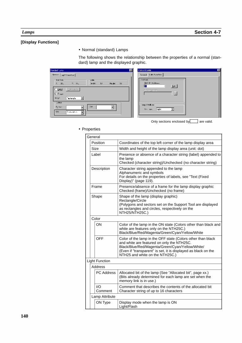
140
Lamps Section 4-7
[Display Functions]
! Normal (standard) Lamps
The following shows the relationship between the properties of a normal (stan-dard) lamp and the displayed graphic.
Only sections enclosed by are valid.
! Properties
General
Position Coordinates of the top left corner of the lamp display area
Size Width and height of the lamp display area (unit: dot)
Label Presence or absence of a character string (label) appended tothe lampChecked (character string)/Unchecked (no character string)
Description Character string appended to the lampAlphanumeric and symbolsFor details on the properties of labels, see ”Text (FixedDisplay)” (page 119).
Frame Presence/absence of a frame for the lamp display graphicChecked (frame)/Unchecked (no frame)
Shape Shape of the lamp (display graphic)Rectangle/Circle(Polygons and sectors set on the Support Tool are displayedas rectangles and circles, respectively on theNTH25/NTH25C.)
Color
ON Color of the lamp in the ON state (Colors other than black andwhite are features only on the NTH25C.)Black/Blue/Red/Magenta/Green/Cyan/Yellow/White
OFF Color of the lamp in the OFF state (Colors other than blackand white are featured on only the NTH25C.Black/Blue/Red/Magenta/Green/Cyan/Yellow/White/(Even if ”transparent” is set, it is displayed as black on theNTH25 and white on the NTH25C.)
Light Function
Address
PC Address Allocated bit of the lamp (See ”Allocated bit”, page xx.)(Bits already determined for each lamp are set when thememory link is in use.)
I/OComment
Comment that describes the contents of the allocated bitCharacter string of up to 16 characters
Lamp Attribute
ON Type Display mode when the lamp is ONLight/Flash
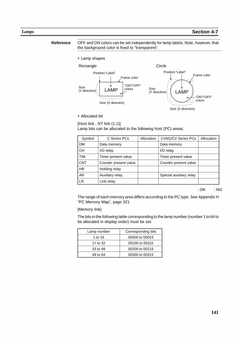
141
Lamps Section 4-7
Reference OFF and ON colors can be set independently for lamp labels. Note, however, thatthe background color is fixed to ”transparent”.
! Lamp shapes
Position “Label”Frame color
Size(Y direction) LAMP
“ON”/“OFF”colors
Size (X direction)
Position “Label”Frame color
Size(Y direction)
“ON”/“OFF”colors
Size (X direction)
Rectangle Circle
LAMP
! Allocated bit
[Host link , NT link (1:1)]Lamp bits can be allocated to the following host (PC) areas.
Symbol C Series PCs Allocation CVM1/CV Series PCs Allocation
DM Data memory � Data memory �CH I/O relay � I/O relay �TIM Timer present value � Timer present value �CNT Counter present value � Counter present value �HR Holding relay � � �AR Auxiliary relay � Special auxiliary relay �LR Link relay � � �
� : OK � : NG
The range of eachmemory area differs according to the PC type. See Appendix H”PC Memory Map”, page 321.
[Memory link]
The bits in the following table corresponding to the lamp number (number 1 to 64 tobe allocated in display order) must be set.
Lamp number Corresponding bits
1 to 16 00000 to 00015
17 to 32 00100 to 00115
33 to 48 00200 to 00215
49 to 64 00300 to 00315
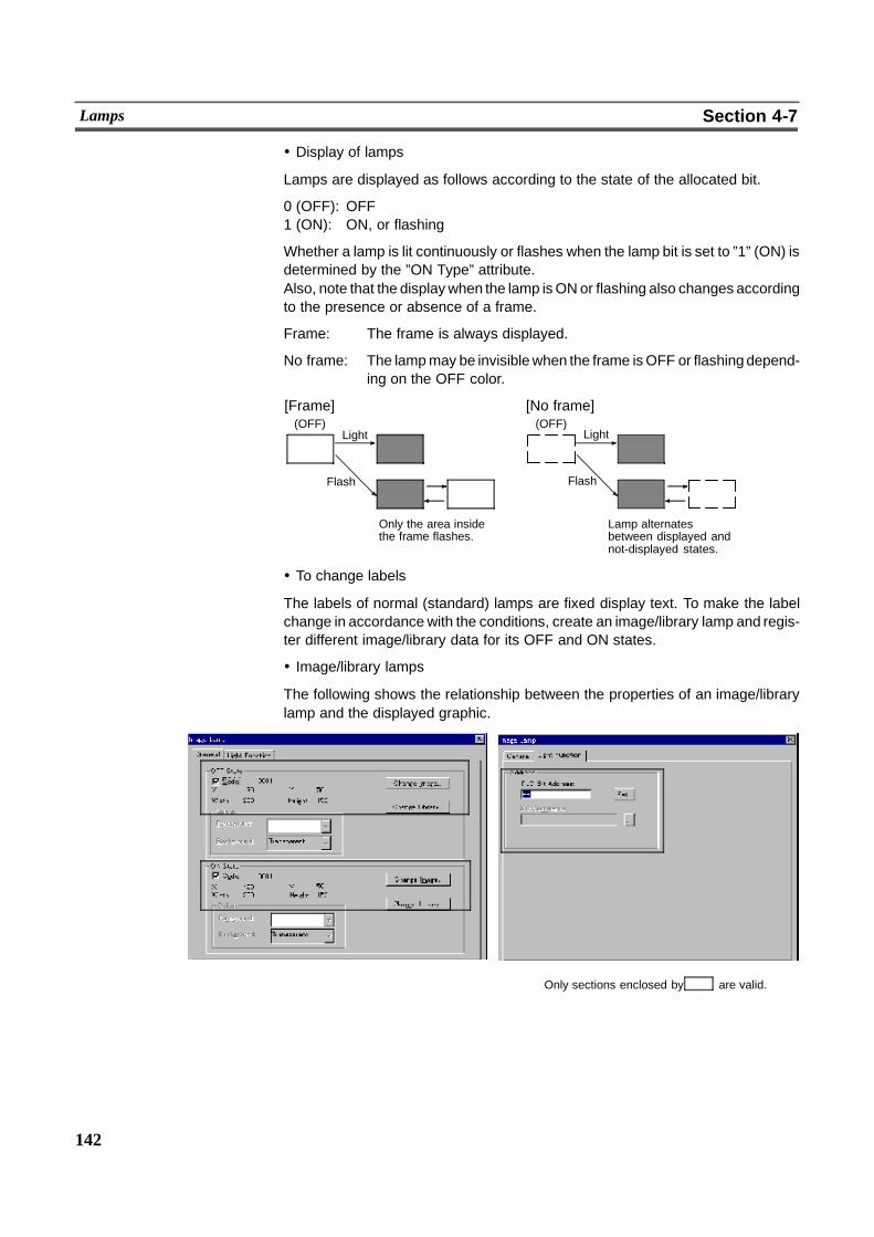
142
Lamps Section 4-7
! Display of lamps
Lamps are displayed as follows according to the state of the allocated bit.
0 (OFF): OFF1 (ON): ON, or flashing
Whether a lamp is lit continuously or flashes when the lamp bit is set to ”1” (ON) isdetermined by the ”ON Type” attribute.Also, note that the displaywhen the lamp isONor flashing also changes accordingto the presence or absence of a frame.
Frame: The frame is always displayed.
No frame: The lampmay be invisiblewhen the frame isOFF or flashingdepend-ing on the OFF color.
[Frame] [No frame](OFF)
Light
Flash
Only the area insidethe frame flashes.
(OFF)
Lamp alternatesbetween displayed andnot-displayed states.
Light
Flash
! To change labels
The labels of normal (standard) lamps are fixed display text. To make the labelchange in accordance with the conditions, create an image/library lamp and regis-ter different image/library data for its OFF and ON states.
! Image/library lamps
The following shows the relationship between the properties of an image/librarylamp and the displayed graphic.
Only sections enclosed by are valid.

143
Lamps Section 4-7
! Properties
General
OFF state
X, Y Coordinates of the top left corner of the image/library datadisplayed in the OFF state
Width, Height Width and height of image/library data displayed in theOFF state
Code Image/library data code displayed in the OFF state
ON State
X, Y Coordinates of the top left corner of the image/library datadisplayed in the ON state
Width, Height Width and height of image/library data displayed in theON state
Code Image/library data code displayed in the ON state
Light Function
Address
PC Bit Address Allocated bit of the lamp (See ”Allocated bit”, below.)
I/O Comments Comment that describes the contents of the allocated bitUp to 16 characters
ON state
Position
OFF state
Position
Allocated bit
[Host link, NT link (1:1)]
Lamp bits can be allocated to the following host (PC) areas.
Symbol C Series PCs Allocation CVM1/CV Series PCs Allocation
DM Data memory � Data memory �CH I/O relay � I/O relay �TIM Timer present value � Timer present value �CNT Counter present value � Counter present value �HR Holding relay � � �AR Auxiliary relay � Special auxiliary relay �LR Link relay � � �
� : OK � : NG
The range of eachmemory area differs according to the PC type. See Appendix H”PC Memory Map”, page 321.
144
Lamps Section 4-7
[Memory link]
The bits in the following table corresponding to the lamp number (number 1 to 64 tobe allocated in display order) must be set.
Lamp number Corresponding bits
1 to 16 00000 to 00015
17 to 32 00100 to 00115
33 to 48 00200 to 00215
49 to 64 00300 to 00315
[Input Functions]
Lamps read the contents of a bit on the host and execute processing in accor-dance with the bit state.Note, however, that the bit is read only in the following case:
- When a lamp is used on the currently displayed screen
[Output Functions]
Lamps have no output function.
[Processing Functions]
Lamps have no data processing function.
[Relationship with Other Elements]
- Lamps overlap with other elements in accordance with the order in which theywere registered on the screen with the Support Tool. Note, however, that youcan change the way in which they overlap using the Support Tool.
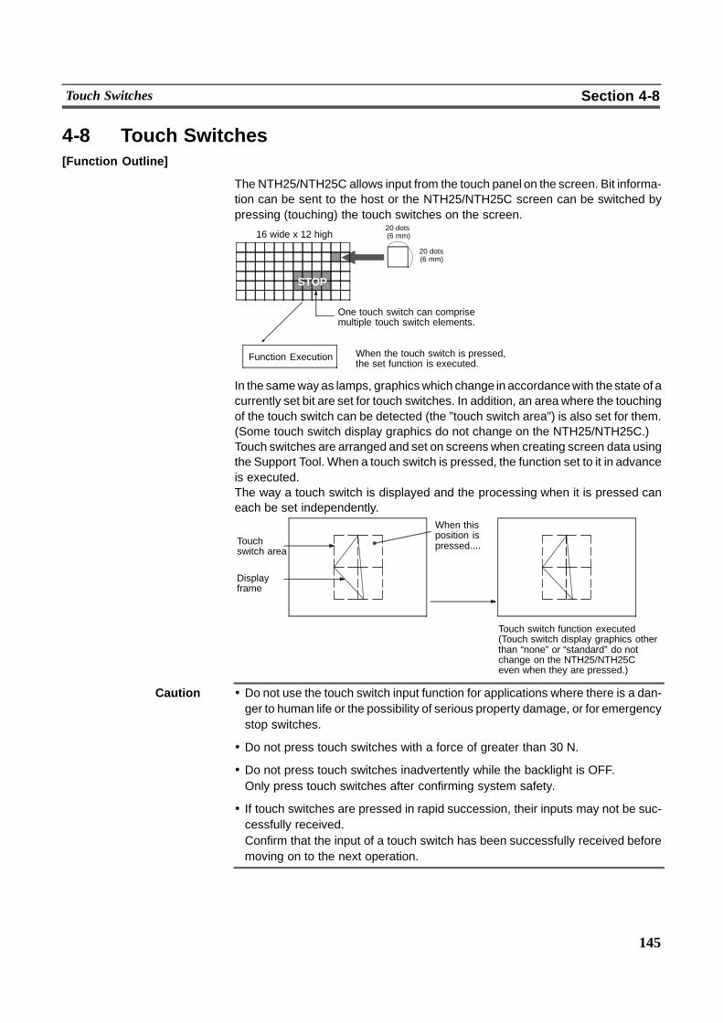
145
Touch Switches Section 4-8
4-8 Touch Switches[Function Outline]
The NTH25/NTH25C allows input from the touch panel on the screen. Bit informa-tion can be sent to the host or the NTH25/NTH25C screen can be switched bypressing (touching) the touch switches on the screen.
16 wide x 12 high20 dots(6 mm)
20 dots(6 mm)
STOP
One touch switch can comprisemultiple touch switch elements.
Function Execution When the touch switch is pressed,the set function is executed.
In the sameway as lamps, graphicswhich change in accordancewith the state of acurrently set bit are set for touch switches. In addition, an area where the touchingof the touch switch can be detected (the ”touch switch area”) is also set for them.(Some touch switch display graphics do not change on the NTH25/NTH25C.)Touch switches are arranged and set on screens when creating screen data usingthe Support Tool. When a touch switch is pressed, the function set to it in advanceis executed.The way a touch switch is displayed and the processing when it is pressed caneach be set independently.
Touch switch function executed(Touch switch display graphics otherthan “none” or “standard” do notchange on the NTH25/NTH25Ceven when they are pressed.)
Touchswitch area
Displayframe
When thisposition ispressed....
Caution ! Do not use the touch switch input function for applications where there is a dan-ger to human life or the possibility of serious property damage, or for emergencystop switches.
! Do not press touch switches with a force of greater than 30 N.
! Do not press touch switches inadvertently while the backlight is OFF.Only press touch switches after confirming system safety.
! If touch switches are pressed in rapid succession, their inputs may not be suc-cessfully received.Confirm that the input of a touch switch has been successfully received beforemoving on to the next operation.
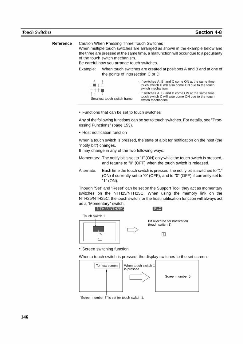
⋅ If switches A, B, and C come ON at the same time,touch switch D will also come ON due to the touchswitch mechanism.
⋅ If switches A, B, and D come ON at the same time,touch switch C will also come ON due to the touchswitch mechanism.
A C
BD
Smallest touch switch frame
146
Touch Switches Section 4-8
Reference Caution When Pressing Three Touch SwitchesWhen multiple touch switches are arranged as shown in the example below andthe three are pressed at the same time, amalfunction will occur due to a peculiarityof the touch switch mechanism.Be careful how you arrange touch switches.Example: When touch switches are created at positions A and B and at one of
the points of intersection C or D
! Functions that can be set to touch switches
Any of the following functions can be set to touch switches. For details, see ”Proc-essing Functions” (page 153).
! Host notification function
When a touch switch is pressed, the state of a bit for notification on the host (the”notify bit”) changes.It may change in any of the two following ways.
Momentary: The notify bit is set to ”1” (ON) only while the touch switch is pressed,and returns to ”0” (OFF) when the touch switch is released.
Alternate: Each time the touch switch is pressed, the notify bit is switched to ”1”(ON) if currently set to ”0” (OFF), and to ”0” (OFF) if currently set to”1” (ON).
Though ”Set” and ”Reset” can be set on the Support Tool, they act as momentaryswitches on the NTH25/NTH25C. When using the memory link on theNTH25/NTH25C, the touch switch for the host notification function will always actas a ”Momentary” switch.
PLC
11(ON)�
NTH25/NTH25C
Bit allocated for notification(touch switch 1)
Touch switch 1
! Screen switching function
When a touch switch is pressed, the display switches to the set screen.
“Screen number 5” is set for touch switch 1.
To next screen When touch switch 1is pressed
Screen number 5
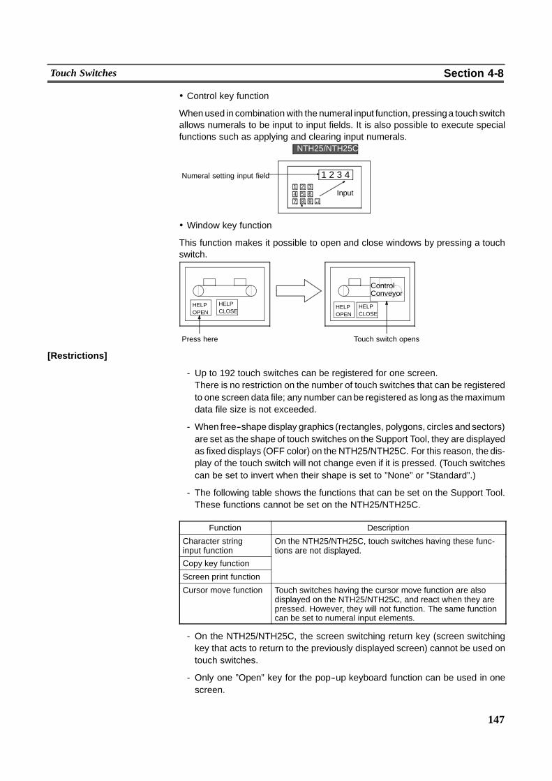
147
Touch Switches Section 4-8
! Control key function
Whenused in combination with the numeral input function, pressinga touchswitchallows numerals to be input to input fields. It is also possible to execute specialfunctions such as applying and clearing input numerals.
Input1 2 34 5 67 8 9
1 2 3 4Numeral setting input field
NTH25/NTH25C
! Window key function
This function makes it possible to open and close windows by pressing a touchswitch.
Touch switch opens
HELPOPEN
Press here
ControlConveyor
HELPOPEN
HELPCLOSE
HELPCLOSE
[Restrictions]
- Up to 192 touch switches can be registered for one screen.There is no restriction on the number of touch switches that can be registeredto one screen data file; any number can be registered as long as themaximumdata file size is not exceeded.
- When free--shape display graphics (rectangles, polygons, circles and sectors)are set as the shape of touch switches on the Support Tool, they are displayedas fixed displays (OFF color) on the NTH25/NTH25C. For this reason, the dis-play of the touch switch will not change even if it is pressed. (Touch switchescan be set to invert when their shape is set to ”None” or ”Standard”.)
- The following table shows the functions that can be set on the Support Tool.These functions cannot be set on the NTH25/NTH25C.
Function Description
Character stringinput function
On the NTH25/NTH25C, touch switches having these func-tions are not displayed.
Copy key function
tions are not displayed.
Screen print function
Cursor move function Touch switches having the cursor move function are alsodisplayed on the NTH25/NTH25C, and react when they arepressed. However, they will not function. The same functioncan be set to numeral input elements.
- On the NTH25/NTH25C, the screen switching return key (screen switchingkey that acts to return to the previously displayed screen) cannot be used ontouch switches.
- Only one ”Open” key for the pop--up keyboard function can be used in onescreen.
148
Touch Switches Section 4-8
- The ”Toggle” key for the pop--up keyboard function acts as the ”Open” key. Forthis reason, when a screen has an ”Open” key and an ”Toggle” key, only onekey, the one with the earlier display order, is enabled.
- When polygons are used as the display graphics for touch switches, one poly-gon can be given up to 255 vertices.
- Restrictions on touch switch labels are the same as for fixed display--text. (Seepage 119.)
- The touch switch display order is the order in which different touch switchtypes were created. Note, however, that the display order of touch switches ofthe same type can be changed using the Support Tool.
- Touch switches are not allowed to overlap each other on theNTH25/NTH25C.Prevent touch switches including those for numeral input, alarm lists and trendgraphs from overlapping.
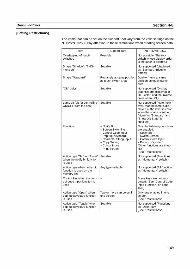
149
Touch Switches Section 4-8
[Setting Restrictions]
The items that can be set on the Support Tool vary from the valid settings on theNTH25/NTH25C. Pay attention to these restrictions when creating screen data.
Item Support Tool NTH25/NTH25C
Overlapping of touchswitches
Possible Not possible (The touchswitch whose display orderis the latter is deleted.)
Shape ”Shadow”, ”3--Di-mension”
Settable Not supported (displayedas ”Standard” (doubleframe))
Shape ”Standard” Rectangle at same positionas touch switch area
Double frame at sameposition as touch switcharea
”ON” color Settable Not supported (Displaygraphics are displayed inOFF color, and the inversecolor when ON.)
Lamp bit (bit for controllingON/OFF from the host)
Settable Not supported (Note, how-ever, that the lamp is dis-played at the inverse colorwhen the shape is set to”None” or ”Standard” and”Show ON State” ischecked.)
Function -- Notify Bit-- Screen Switching-- Control Code Input-- Pop--up Keyboard-- Character String Input-- Copy Setting-- Cursor Move-- Print Screen
Only the following functionsare enabled:-- Notify Bit-- Switch Screen-- Control Code Input-- Pop--up Keyboard(Other functions are inval-id.)(See ”Restrictions”.)
Action type ”Set” or ”Reset”when the notify bit functionis used
Settable Not supported (Functionsas ”Momentary” switch.)
Action type when notify bitfunction is used on thememory link
Any type settable Not supported (All functionas ”Momentary” switch.)
Control key when the con-trol code input function isused
-- Some keys are not sup-ported. (See ”Control CodeInput Function” on page156.)
Action type ”Open” whenpop--up keyboard functionis used
Two or more can be set inone screen.
Only one enabled in onescreen.(See ”Restrictions”.)
Action type ”Toggle” whenpop--up keyboard functionis used
Settable Not supported (Functionsas ”Open” key.)(See ”Restrictions”.)
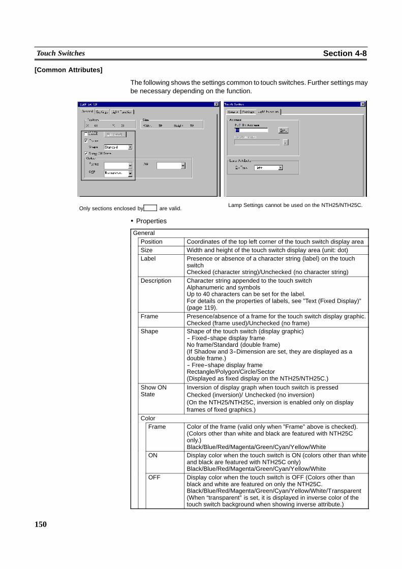
150
Touch Switches Section 4-8
[Common Attributes]
The following shows the settings common to touch switches. Further settingsmaybe necessary depending on the function.
Only sections enclosed by are valid. Lamp Settings cannot be used on the NTH25/NTH25C.
! Properties
GeneralPosition Coordinates of the top left corner of the touch switch display areaSize Width and height of the touch switch display area (unit: dot)Label Presence or absence of a character string (label) on the touch
switchChecked (character string)/Unchecked (no character string)
Description Character string appended to the touch switchAlphanumeric and symbolsUp to 40 characters can be set for the label.For details on the properties of labels, see ”Text (Fixed Display)”(page 119).
Frame Presence/absence of a frame for the touch switch display graphic.Checked (frame used)/Unchecked (no frame)
Shape Shape of the touch switch (display graphic)-- Fixed--shape display frameNo frame/Standard (double frame)(If Shadow and 3--Dimension are set, they are displayed as adouble frame.)-- Free--shape display frameRectangle/Polygon/Circle/Sector(Displayed as fixed display on the NTH25/NTH25C.)
Show ONState
Inversion of display graph when touch switch is pressedChecked (inversion)/ Unchecked (no inversion)(On the NTH25/NTH25C, inversion is enabled only on displayframes of fixed graphics.)
ColorFrame Color of the frame (valid only when ”Frame” above is checked).
(Colors other than white and black are featured with NTH25Conly.)Black/Blue/Red/Magenta/Green/Cyan/Yellow/White
ON Display color when the touch switch is ON (colors other than whiteand black are featured with NTH25C only)Black/Blue/Red/Magenta/Green/Cyan/Yellow/White
OFF Display color when the touch switch is OFF (Colors other thanblack and white are featured on only the NTH25C.Black/Blue/Red/Magenta/Green/Cyan/Yellow/White/Transparent(When “transparent” is set, it is displayed in inverse color of thetouch switch background when showing inverse attribute.)
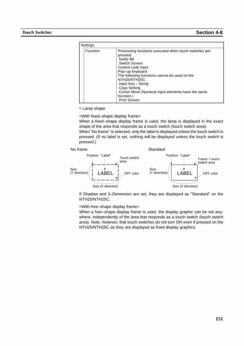
151
Touch Switches Section 4-8
Settings
Function Processing functions executed when touch switches arepressedNotify BitSwitch ScreenControl code inputPop--up keyboardThe following functions cannot be used on theNTH25/NTH25C.Input Key -- StringCopy SettingCursor Move (Numeral input elements have the samefunction.)Print Screen
! Lamp shape
<With fixed--shape display frame>When a fixed--shape display frame is used, the lamp is displayed in the exactshape of the area that responds as a touch switch (touch switch area).When ”No frame” is selected, only the label is displayed unless the touch switch ispressed. (If no label is set, nothing will be displayed unless the touch switch ispressed.)
No framePosition “Label”
Touch switcharea
Size(Y direction) LABEL
Size (X direction)
Position “Label”
Size(Y direction) LABEL
Size (X direction)
OFF colorOFF color
Frame = touchswitch area
Standard
If Shadow and 3--Dimension are set, they are displayed as ”Standard” on theNTH25/NTH25C.
<With free--shape display frame>When a free--shape display frame is used, the display graphic can be set any-where, independently of the area that responds as a touch switch (touch switcharea). Note, however, that touch switches do not turn ON even if pressed on theNTH25/NTH25C as they are displayed as fixed display graphics.
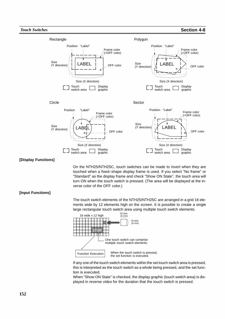
152
Touch Switches Section 4-8
Rectangle Polygon
Position “Label”Frame color(=OFF color)
Size(Y direction) LABEL OFF color
Size (X direction)
Touchswitch area
Displaygraphic
Circle Sector
Position “Label”Frame color(=OFF color)
Size(Y direction) LABEL
OFF color
Position “Label”Frame color(=OFF color)
Size(Y direction) OFF color
Position “Label”Frame color(=OFF color)
Size(Y direction)
OFF color
Size (X direction)
Size (X direction) Size (X direction)
Touchswitch area
Displaygraphic
LABEL
LABEL
Touchswitch area
Displaygraphic
Touchswitch area
Displaygraphic
[Display Functions]
On the NTH25/NTH25C, touch switches can be made to invert when they aretouched when a fixed--shape display frame is used. If you select ”No frame” or”Standard” as the display frame and check ”Show ON State”, the touch area willturn ON when the touch switch is pressed. (The area will be displayed at the in-verse color of the OFF color.)
[Input Functions]
The touch switch elements of the NTH25/NTH25C are arranged in a grid 16 ele-ments wide by 12 elements high on the screen. It is possible to create a singlelarge rectangular touch switch area using multiple touch switch elements.
16 wide x 12 high20 dots(6 mm)
20 dots(6 mm)
STOP
One touch switch can comprisemultiple touch switch elements.
Function Execution When the touch switch is pressed,the set function is executed.
If any one of the touch switch elements within the set touch switch area is pressed,this is interpreted as the touch switch as a whole being pressed, and the set func-tion is executed.When ”Show ON State” is checked, the display graphic (touch switch area) is dis-played in reverse video for the duration that the touch switch is pressed.
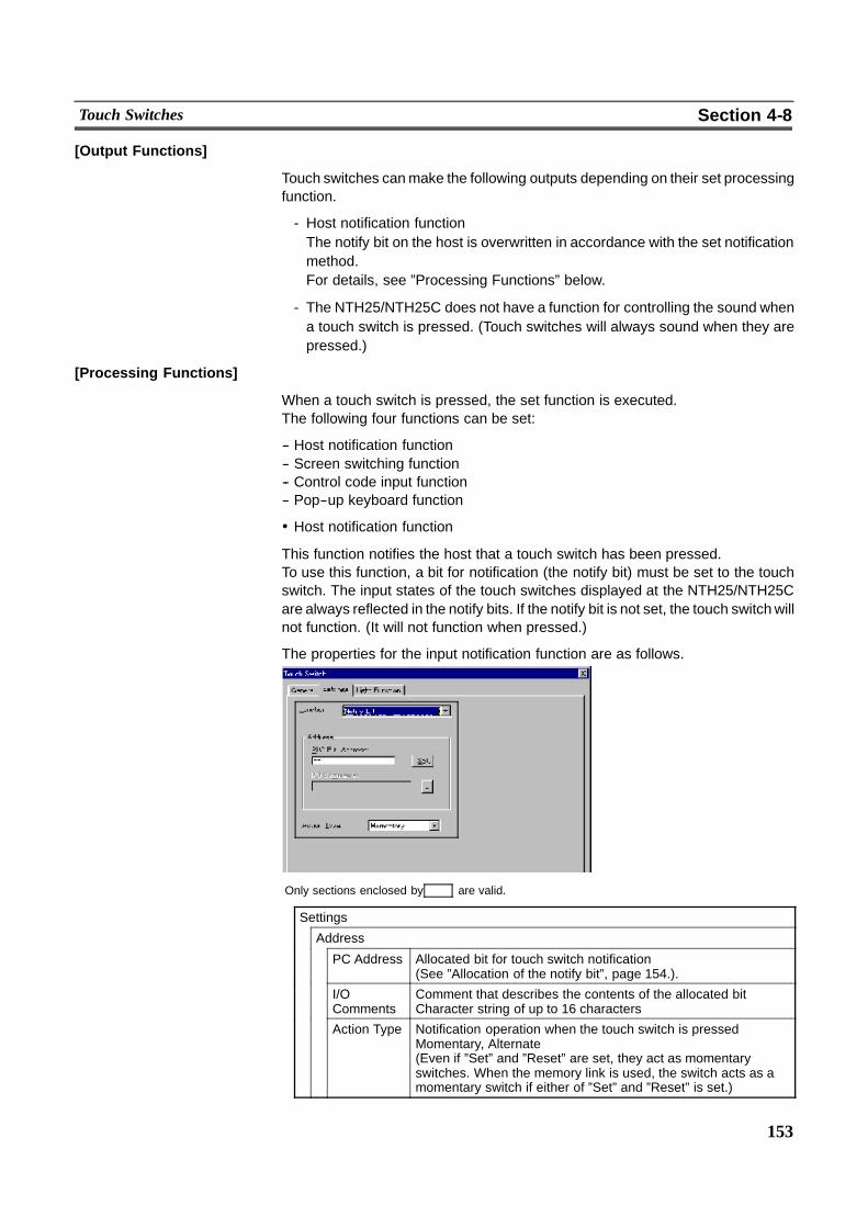
153
Touch Switches Section 4-8
[Output Functions]
Touch switches canmake the following outputs depending on their set processingfunction.
- Host notification functionThe notify bit on the host is overwritten in accordance with the set notificationmethod.For details, see ”Processing Functions” below.
- The NTH25/NTH25C does not have a function for controlling the sound whena touch switch is pressed. (Touch switches will always sound when they arepressed.)
[Processing Functions]
When a touch switch is pressed, the set function is executed.The following four functions can be set:
-- Host notification function-- Screen switching function-- Control code input function-- Pop--up keyboard function
! Host notification function
This function notifies the host that a touch switch has been pressed.To use this function, a bit for notification (the notify bit) must be set to the touchswitch. The input states of the touch switches displayed at the NTH25/NTH25Care always reflected in the notify bits. If the notify bit is not set, the touch switchwillnot function. (It will not function when pressed.)
The properties for the input notification function are as follows.
Only sections enclosed by are valid.
Settings
Address
PC Address Allocated bit for touch switch notification(See ”Allocation of the notify bit”, page 154.).
I/OComments
Comment that describes the contents of the allocated bitCharacter string of up to 16 characters
Action Type Notification operation when the touch switch is pressedMomentary, Alternate(Even if ”Set” and ”Reset” are set, they act as momentaryswitches. When the memory link is used, the switch acts as amomentary switch if either of ”Set” and ”Reset” is set.)
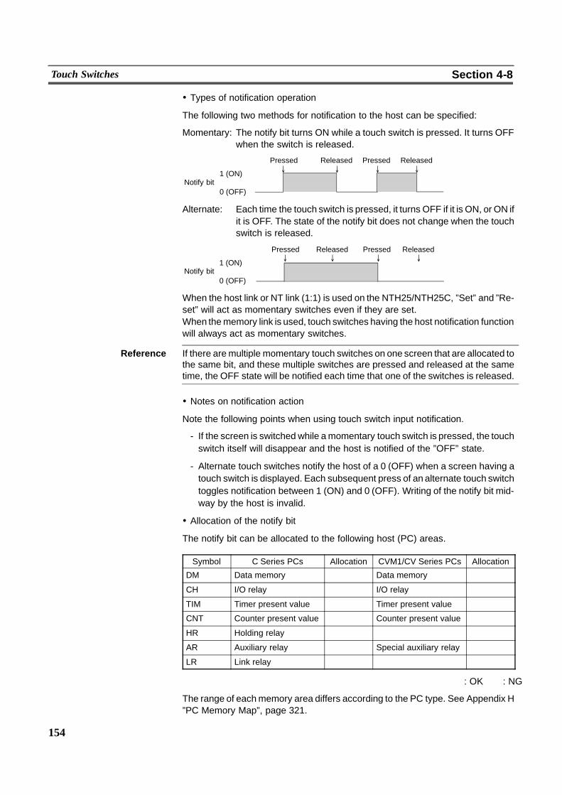
154
Touch Switches Section 4-8
! Types of notification operation
The following two methods for notification to the host can be specified:
Momentary: The notify bit turns ON while a touch switch is pressed. It turns OFFwhen the switch is released.
Pressed Released
Notify bit0 (OFF)
Pressed Released' ' ' '
1 (ON)
Alternate: Each time the touch switch is pressed, it turns OFF if it is ON, or ON ifit is OFF. The state of the notify bit does not change when the touchswitch is released.
Pressed Released Pressed Released' ' ' '
Notify bit0 (OFF)
1 (ON)
When the host link or NT link (1:1) is used on the NTH25/NTH25C, ”Set” and ”Re-set” will act as momentary switches even if they are set.When thememory link is used, touch switches having the host notification functionwill always act as momentary switches.
Reference If there aremultiple momentary touch switches on one screen that are allocated tothe same bit, and these multiple switches are pressed and released at the sametime, the OFF state will be notified each time that one of the switches is released.
! Notes on notification action
Note the following points when using touch switch input notification.
- If the screen is switched while amomentary touch switch is pressed, the touchswitch itself will disappear and the host is notified of the ”OFF” state.
- Alternate touch switches notify the host of a 0 (OFF) when a screen having atouch switch is displayed. Each subsequent press of an alternate touch switchtoggles notification between 1 (ON) and 0 (OFF). Writing of the notify bit mid-way by the host is invalid.
! Allocation of the notify bit
The notify bit can be allocated to the following host (PC) areas.
Symbol C Series PCs Allocation CVM1/CV Series PCs Allocation
DM Data memory � Data memory �CH I/O relay � I/O relay �TIM Timer present value � Timer present value �CNT Counter present value � Counter present value �HR Holding relay � � �AR Auxiliary relay � Special auxiliary relay �LR Link relay � � �
� : OK � : NG
The range of eachmemory area differs according to the PC type. See Appendix H”PC Memory Map”, page 321.
155
Touch Switches Section 4-8
! Screen switching function
This function allows the screen to be switched by touch switch operation on theNTH25/NTH25C, without instructions from the host.To use this function, the screen number to be displayed must be set to the touchswitch. When the touch switch is pressed during NTH25/NTH25C operation, thedisplay switches to the set screen. (At this time, the new screen number is notifiedvia the PT status notify area.)
Reference - When a screen with a number other than a settable is allocated to a touchswitch, the screen does not switch and the currently displayed screen remainsdisplayed.
- The screen can also be switched by PT status control area operation (page 90).
- On the NTH25/NTH25C, touch switches having the screen switching functiononly act to write new screen numbers to the ”Screen switch setting” in the PTstatus control area. Actual screen switching action is executed byNTH25/NTH25C reading ”Screen switch setting”. So, note that pressing a touchswitch will not switch a screen if communications trouble, for example, is pre-venting communications with the host.
The attributes for screen switching are as follows.
Only sections enclosed by are valid.
Settings
Screen number Screen number of screen to be newly displayed1 to 1000, 9020
! Specified screen number and display operation
The display operation on the NTH25/NTH25C depends on the specified screennumber, as follows.
Screen numbers 1 to 1000:The display switches to the screen with the currently set screen num-ber. The host is notified of the screen number of the newly displayedscreen.
156
Touch Switches Section 4-8
Screen number 9020:The programming console screen is displayed. The host is notified ofscreen number 9020.Thismakes it possible to use the programming console function evenin the RUN mode.(Note, however, that the programming console function can be usedonly when the PT is connected to a PC which can use the program-ming console function.)The PT’s RUN mode is canceled while the programming function isbeing used. Monitoring of PT status control area, the data loggingfunction for trend graphs andmonitoring of the alarm history also arenot performed.To return from the programming console function, exit this function,by PT operation. (It is not possible to exit this function from the host.)
On the NTH25/NTH25C, the screen switching return key (screen switching keythat acts to return to the previously displayed screen) cannot be used on touchswitches.
! Control code input function
Control keys are used as numeral keys (0 to 9, A to F) when the numeral inputfunction is used, and as special keys with fixed functions. By allocating a specificcontrol key to a touch switch, it can be used to execute a specific function.
The attributes for control keys are as follows.
Only sections enclosed by are valid.
Settings
Control key Control key to be set
157
Touch Switches Section 4-8
The following functions can be set to touch switch control keys.
Key Function
0 to 9, A to F Used to input numerals (1 digit)
CLR Clears numeric values in input fields
. Used to input a decimal point
*1 Applies input without shifting to another input field (same as ENT)
ENT*1 Applies input without shifting to another input field (same as )
*1 Only one of the and ENT keys can be registered to a screen. Though two or more ofthese keys canbe registered on theSupport Tool, only the first one in the display order isvalid; the others will be deleted.
Keys other than the above can be set on the Support Tool. However, these keyswill not actually function even if they can be displayed on the NTH25/NTH25C.
! Pop--up window/keyboard function
This function is used to control the opening and closing of windowswhen using thewindow function. (See ”Window Function”, page 211.)
The attributes for the window key are as follows.
Only sections enclosed by are valid.
SettingsScreen No.
Local 1(keyboard)
Check this attribute when the window is to be controlled.(fixed as checked)-- Specify the screen number of the window to be controlled.1 to 1000
Action Type Controlling method of the windowOpen/Close(Setting toggle action will result in an open action.)
158
Touch Switches Section 4-8
! Behavior according to ”Action Type”
Open : Opens the specified window.Whether or not the window is actually opened depends on the win-dow display state.The window is displayed at the position that was specified when itwas created.If another window of the same type is already opened, nothing will beexecuted even if the touch switch is pressed.If the specified window does not exist, no operation is performed.Only one ”Open” key can be registered to one screen.
Close : Closes the specified window.When the ”close” window key is pressed, the window currentlydisplayed is closed.
Though ”Toggle” can be set as the action type on the Support Tool, this type acts asan open key on the NTH25/NTH25C.Only one of the ”Open” and ”Toggle” keys can be registered to a screen. Thoughtwo or more of these keys can be registered on the Support Tool, only the first onein the display order is valid; the others will be deleted.
[Relationship with Other Elements]
- Numerals can be input by using control keys in combination with ”Numeral In-put” (page 196).Registering an input control key to a window in advance allows you to use theentire of the base screen.
- Special touch switches (control keys) with specific functions are automaticallycreated for the following elements.Trend graphs (page 176), alarm list (page 189), alarm history (page 189), nu-meral input (page 196), thumbwheel switches (page 203)
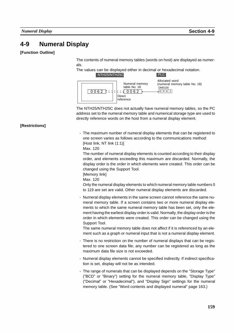
159
Numeral Display Section 4-9
4-9 Numeral Display[Function Outline]
The contents of numeral memory tables (words on host) are displayed as numer-als.The values can be displayed either in decimal or hexadecimal notation.
Allocated word(numeral memory table No. 18)DM0100
0 0 6 2 0 0 6 2 0 0 6 2
Directreference
Numeral memorytable No. 18
PLCNTH25/NTH25C
The NTH25/NTH25C does not actually have numeral memory tables, so the PCaddress set to the numeral memory table and numerical storage type are used todirectly reference words on the host from a numeral display element.
[Restrictions]
- The maximum number of numeral display elements that can be registered toone screen varies as follows according to the communications method:[Host link, NT link (1:1)]Max. 120The number of numeral display elements is counted according to their displayorder, and elements exceeding this maximum are discarded. Normally, thedisplay order is the order in which elements were created. This order can bechanged using the Support Tool.[Memory link]Max. 120Only the numeral display elements to which numeral memory table numbers 0to 119 are set are valid. Other numeral display elements are discarded.
- Numeral display elements in the same screen cannot reference the same nu-meral memory table. If a screen contains two or more numeral display ele-ments to which the same numeral memory table has been set, only the ele-ment having the earliest display order is valid. Normally, the displayorder is theorder in which elements were created. This order can be changed using theSupport Tool.The same numeral memory table does not affect if it is referenced by an ele-ment such as a graph or numeral input that is not a numeral display element.
- There is no restriction on the number of numeral displays that can be regis-tered to one screen data file; any number can be registered as long as themaximum data file size is not exceeded.
- Numeral display elements cannot be specified indirectly. If indirect specifica-tion is set, display will not be as intended.
- The range of numerals that can be displayed depends on the ”Storage Type”(”BCD” or ”Binary”) setting for the numeral memory table, ”Display Type”(”Decimal” or ”Hexadecimal”), and ”Display Sign” settings for the numeralmemory table. (See ”Word contents and displayed numeral” page 163.)
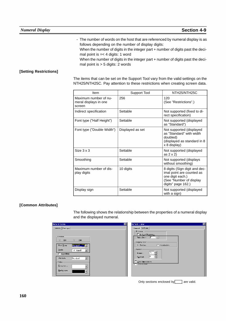
160
Numeral Display Section 4-9
- The number of words on the host that are referenced by numeral display is asfollows depending on the number of display digits:When the number of digits in the integer part + number of digits past the deci-mal point is =< 4 digits: 1 wordWhen the number of digits in the integer part + number of digits past the deci-mal point is > 5 digits: 2 words
[Setting Restrictions]
The items that can be set on the Support Tool vary from the valid settings on theNTH25/NTH25C. Pay attention to these restrictions when creating screen data.
Item Support Tool NTH25/NTH25C
Maximum number of nu-meral displays in onescreen
256 120(See ”Restrictions”.)
Indirect specification Settable Not supported (fixed to di-rect specification)
Font type (”Half Height”) Settable Not supported (displayedas ”Standard”)
Font type (”Double Width”) Displayed as set Not supported (displayedas ”Standard” with widthdoubled)(displayed as standard in 8x 8 display)
Size 3 x 3 Settable Not supported (displayedas 2 x 2)
Smoothing Settable Not supported (displayswithout smoothing)
Maximum number of dis-play digits
10 digits 8 digits (Sign digit and dec-imal point are counted asone digit each.)(See ”Number of displaydigits” page 162.)
Display sign Settable Not supported (displayedwith a sign)
[Common Attributes]
The following shows the relationship between the properties of a numeral displayand the displayed numeral.
Only sections enclosed by are valid.
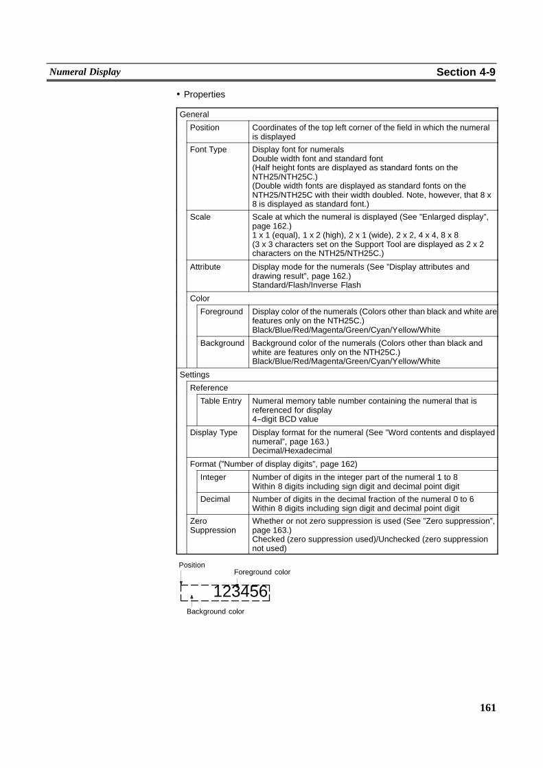
161
Numeral Display Section 4-9
! Properties
General
Position Coordinates of the top left corner of the field in which the numeralis displayed
Font Type Display font for numeralsDouble width font and standard font(Half height fonts are displayed as standard fonts on theNTH25/NTH25C.)(Double width fonts are displayed as standard fonts on theNTH25/NTH25C with their width doubled. Note, however, that 8 x8 is displayed as standard font.)
Scale Scale at which the numeral is displayed (See ”Enlarged display”,page 162.)1 x 1 (equal), 1 x 2 (high), 2 x 1 (wide), 2 x 2, 4 x 4, 8 x 8(3 x 3 characters set on the Support Tool are displayed as 2 x 2characters on the NTH25/NTH25C.)
Attribute Display mode for the numerals (See ”Display attributes anddrawing result”, page 162.)Standard/Flash/Inverse Flash
Color
Foreground Display color of the numerals (Colors other than black and white arefeatures only on the NTH25C.)Black/Blue/Red/Magenta/Green/Cyan/Yellow/White
Background Background color of the numerals (Colors other than black andwhite are features only on the NTH25C.)Black/Blue/Red/Magenta/Green/Cyan/Yellow/White
Settings
Reference
Table Entry Numeral memory table number containing the numeral that isreferenced for display4--digit BCD value
Display Type Display format for the numeral (See ”Word contents and displayednumeral”, page 163.)Decimal/Hexadecimal
Format (”Number of display digits”, page 162)
Integer Number of digits in the integer part of the numeral 1 to 8Within 8 digits including sign digit and decimal point digit
Decimal Number of digits in the decimal fraction of the numeral 0 to 6Within 8 digits including sign digit and decimal point digit
ZeroSuppression
Whether or not zero suppression is used (See ”Zero suppression”,page 163.)Checked (zero suppression used)/Unchecked (zero suppressionnot used)
Background color
123456
PositionForeground color
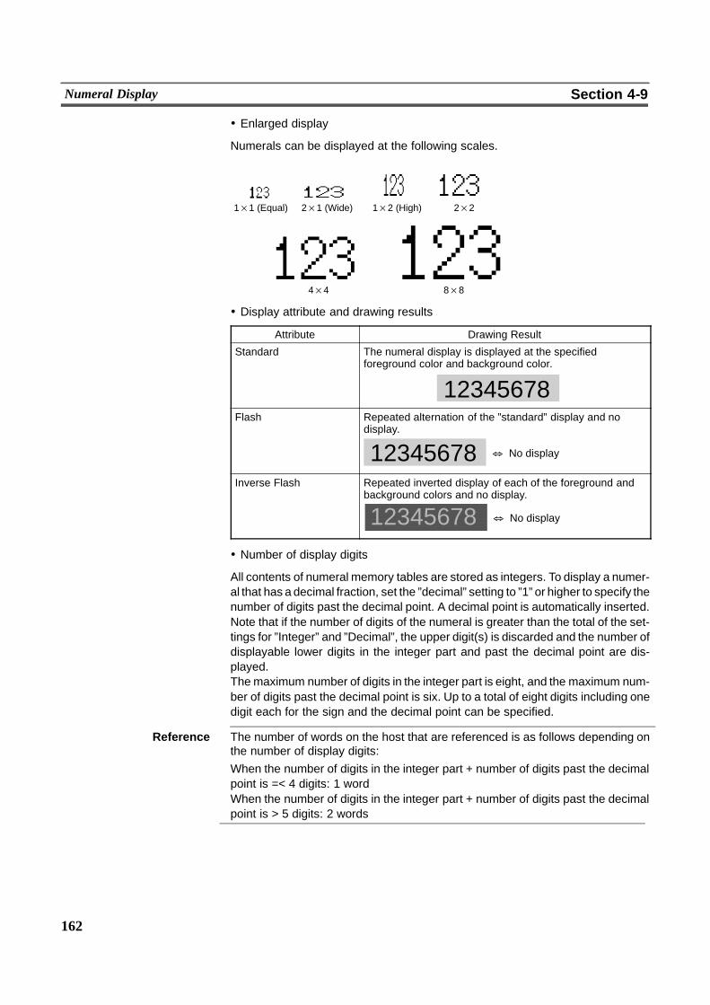
162
Numeral Display Section 4-9
! Enlarged display
Numerals can be displayed at the following scales.
4×4 8×8
1×1 (Equal) 2×1 (Wide) 1×2 (High) 2×2
! Display attribute and drawing results
Attribute Drawing Result
Standard The numeral display is displayed at the specifiedforeground color and background color.
12345678Flash Repeated alternation of the ”standard” display and no
display.
& No display12345678Inverse Flash Repeated inverted display of each of the foreground and
background colors and no display.
12345678 & No display
! Number of display digits
All contents of numeral memory tables are stored as integers. To display a numer-al that has a decimal fraction, set the ”decimal” setting to ”1” or higher to specify thenumber of digits past the decimal point. A decimal point is automatically inserted.Note that if the number of digits of the numeral is greater than the total of the set-tings for ”Integer” and ”Decimal”, the upper digit(s) is discarded and the number ofdisplayable lower digits in the integer part and past the decimal point are dis-played.Themaximum number of digits in the integer part is eight, and the maximum num-ber of digits past the decimal point is six. Up to a total of eight digits including onedigit each for the sign and the decimal point can be specified.
Reference The number of words on the host that are referenced is as follows depending onthe number of display digits:When the number of digits in the integer part + number of digits past the decimalpoint is =< 4 digits: 1 wordWhen the number of digits in the integer part + number of digits past the decimalpoint is > 5 digits: 2 words

163
Numeral Display Section 4-9
In the following example, let us assume that ”Zero Suppression” is set to ”None”.
Example: Displaying ”123456”-- Setting for ”Integer” = 8 and ”Decimal” = 0:
Resulting display: 00123456-- Setting for ”Integer” = 4 and ”Decimal” = 4:
Resulting display: 012.3456-- Setting for ”Integer” = 2 and ”Decimal” = 4:
Resulting display: 12.3456-- Setting for ”Integer” = 1 and ”Decimal” = 4:
Resulting display: 2.3456
! Zero suppression
The numeral is displayed right--justified within the sum of the numberof digits specified for ”Integer” and the number of digits specified for ”Decimal”.Normally, when the number of digits of the numeral is small, the excessdigits to theleft are filled with zeros. When ”Zero Suppression” is checked, no zeros are set inthe excess digits and they are left blank.
Without zero suppression(when the number of digits displayed is 8)
With zero suppression
! Word contents and displayed numeral
The range of numerals that can be displayed depends on the following settings:
Numeral storage type (BCD/binary)Display Type (”Decimal”/”Hexadecimal”)
<Function of Numeral Storage Type>The numeral storage type determines whether the contents of words on the hostare recognized as BCD (Binary Coded Decimal) or binary (hexadecimal).When BCD is set, a word on the host is judged to be a minus number if its upper-most digit is ”F”. (The number of valid digits of a minus number is one digit less.)”Uppermost digit” here refers to bits 12 to 15whenoneword is referenced, and bits12 to 15 of the second word when two words are referenced.Whenbinary is set, words on the host are handled as signed binary data, so awordis judged to be aminus number when its uppermost digit is ”1” (ON). (The numeralis handled as 2’s complement.) ”Uppermost digit” here refers to bit 15 when oneword is referenced, and bit 15 of the secondword when two words are referenced.
<Function of Display Type>The display type determines whether display is decimal or hexadecimal.
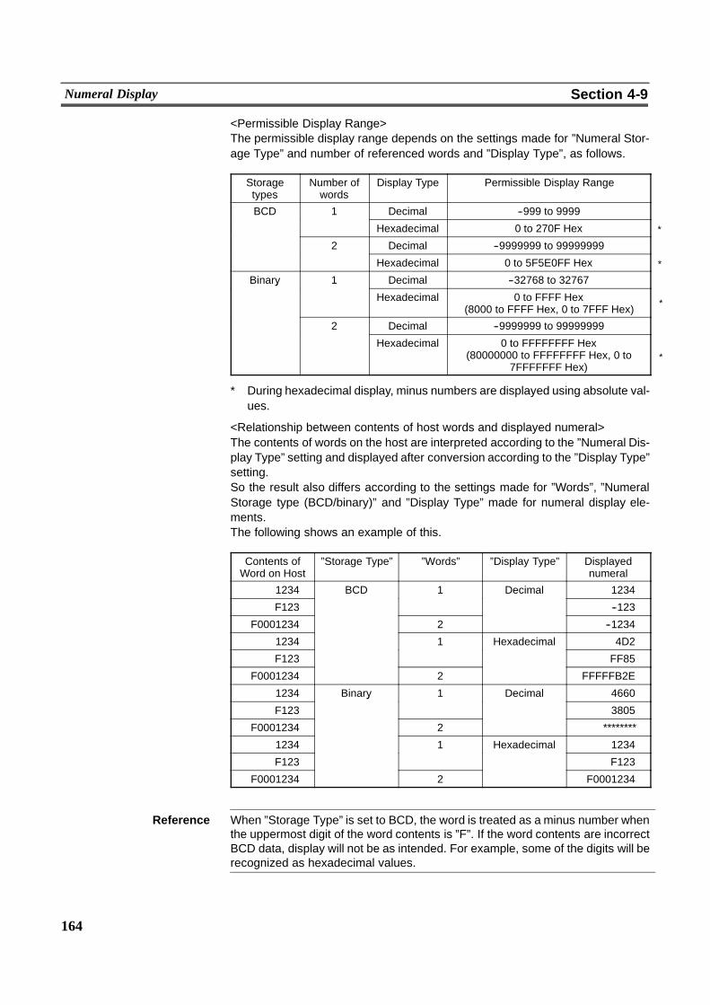
*
*
*
*
164
Numeral Display Section 4-9
<Permissible Display Range>The permissible display range depends on the settings made for ”Numeral Stor-age Type” and number of referenced words and ”Display Type”, as follows.
Storagetypes
Number ofwords
Display Type Permissible Display Range
BCD 1 Decimal --999 to 9999
Hexadecimal 0 to 270F Hex
2 Decimal --9999999 to 99999999
Hexadecimal 0 to 5F5E0FF Hex
Binary 1 Decimal --32768 to 32767y
Hexadecimal 0 to FFFF Hex(8000 to FFFF Hex, 0 to 7FFF Hex)
2 Decimal --9999999 to 99999999
Hexadecimal 0 to FFFFFFFF Hex(80000000 to FFFFFFFF Hex, 0 to
7FFFFFFF Hex)
* During hexadecimal display, minus numbers are displayed using absolute val-ues.
<Relationship between contents of host words and displayed numeral>The contents of words on the host are interpreted according to the ”Numeral Dis-play Type” setting and displayed after conversion according to the ”Display Type”setting.So the result also differs according to the settings made for ”Words”, ”NumeralStorage type (BCD/binary)” and ”Display Type” made for numeral display ele-ments.The following shows an example of this.
Contents ofWord on Host
”Storage Type” ”Words” ”Display Type” Displayednumeral
1234 BCD 1 Decimal 1234
F123 --123
F0001234 2 --1234
1234 1 Hexadecimal 4D2
F123 FF85
F0001234 2 FFFFFB2E
1234 Binary 1 Decimal 4660
F123
y
3805
F0001234 2 ********
1234 1 Hexadecimal 1234
F123 F123
F0001234 2 F0001234
Reference When ”Storage Type” is set to BCD, the word is treated as a minus number whenthe uppermost digit of the word contents is ”F”. If the word contents are incorrectBCD data, display will not be as intended. For example, some of the digits will berecognized as hexadecimal values.
165
Numeral Display Section 4-9
[Display Functions]
In numeral display, numerals are displayed in accordance with the ”General” set-tings.For details on the display mode according to the ”General” settings, see ”CommonAttributes”.
[Input Functions]
Numeral displays do not have a direct input function as they display the contents ofwords on the host via numeral memory tables. Note, however, that theNTH25/NTH25C does not actually have numeral memory tables, so actually thenumeral display reads the contents of words on the host.
[Output Functions]
Numeral displays have no output function.
[Processing Functions]
With numeral displays, the contents of words on the host are converted to displaynumerals in accordance with the ”Numeral Storage Type” of the specified numeralmemory table and the ”Properties” setting for the numeral display element. Fordetails, see ”Common Attributes”.
[Relationship with Other Elements]
- The same conversionmethod and display mode used with numeral displays isused when displaying numerals by ”numeral input” (page 196).
Numeral displays overlap other elements in accordance with the order in whichthey were registered to the screen using the Support Tool. Note, however, that youcan change the way in which they overlap using the Support Tool.
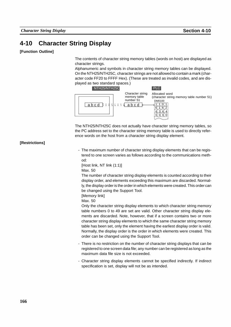
166
Character String Display Section 4-10
4-10 Character String Display[Function Outline]
The contents of character string memory tables (words on host) are displayed ascharacter strings.Alphanumeric and symbols in character string memory tables can be displayed.On theNTH25/NTH25C, character strings are not allowed to contain amark (char-acter code FF20 to FFFF Hex). (These are treated as invalid codes, and are dis-played as two standard spaces.)
12
PLCNTH25/NTH25C
Allocated word(character string memory table number 51)DM0100
a b c d a b c d 1 1 06 1 6
Character stringmemory tablenumber 51
6 3 6 40 0 0 0
The NTH25/NTH25C does not actually have character string memory tables, sothe PC address set to the character string memory table is used to directly refer-ence words on the host from a character string display element.
[Restrictions]
- The maximum number of character string display elements that can be regis-tered to one screen varies as follows according to the communications meth-od:[Host link, NT link (1:1)]Max. 50The number of character string display elements is counted according to theirdisplay order, and elements exceeding this maximum are discarded. Normal-ly, the display order is the order inwhich elementswere created. This order canbe changed using the Support Tool.[Memory link]Max. 50Only the character string display elements to which character string memorytable numbers 0 to 49 are set are valid. Other character string display ele-ments are discarded. Note, however, that if a screen contains two or morecharacter string display elements to which the same character string memorytable has been set, only the element having the earliest display order is valid.Normally, the display order is the order in which elements were created. Thisorder can be changed using the Support Tool.
- There is no restriction on the number of character string displays that can beregistered to one screen data file; any number can be registered as long as themaximum data file size is not exceeded.
- Character string display elements cannot be specified indirectly. If indirectspecification is set, display will not be as intended.
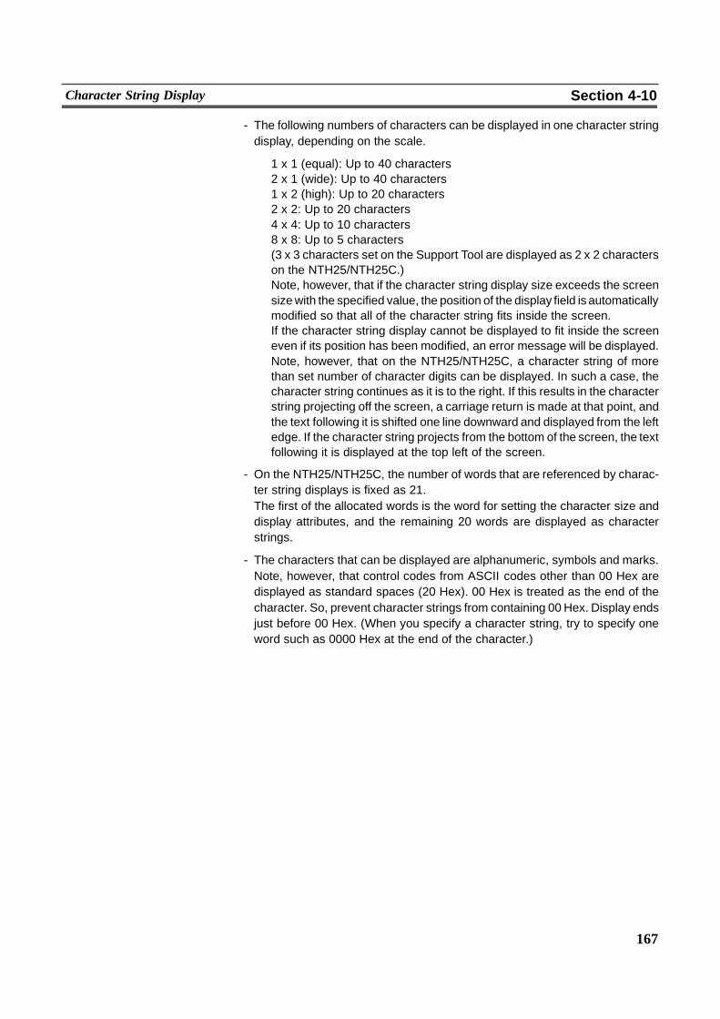
167
Character String Display Section 4-10
- The following numbers of characters can be displayed in one character stringdisplay, depending on the scale.
1 x 1 (equal): Up to 40 characters2 x 1 (wide): Up to 40 characters1 x 2 (high): Up to 20 characters2 x 2: Up to 20 characters4 x 4: Up to 10 characters8 x 8: Up to 5 characters(3 x 3 characters set on the Support Tool are displayed as 2 x 2 characterson the NTH25/NTH25C.)Note, however, that if the character string display size exceeds the screensizewith the specified value, the position of the display field is automaticallymodified so that all of the character string fits inside the screen.If the character string display cannot be displayed to fit inside the screeneven if its position has been modified, an error message will be displayed.Note, however, that on the NTH25/NTH25C, a character string of morethan set number of character digits can be displayed. In such a case, thecharacter string continues as it is to the right. If this results in the characterstring projecting off the screen, a carriage return is made at that point, andthe text following it is shifted one line downward and displayed from the leftedge. If the character string projects from the bottom of the screen, the textfollowing it is displayed at the top left of the screen.
- On the NTH25/NTH25C, the number of words that are referenced by charac-ter string displays is fixed as 21.The first of the allocated words is the word for setting the character size anddisplay attributes, and the remaining 20 words are displayed as characterstrings.
- The characters that can be displayed are alphanumeric, symbols and marks.Note, however, that control codes from ASCII codes other than 00 Hex aredisplayed as standard spaces (20 Hex). 00 Hex is treated as the end of thecharacter. So, prevent character strings from containing 00 Hex. Display endsjust before 00 Hex. (When you specify a character string, try to specify oneword such as 0000 Hex at the end of the character.)

168
Character String Display Section 4-10
[Setting Restrictions]
The items that can be set on the Support Tool vary from the valid settings on theNTH25/NTH25C. Pay attention to these restrictions when creating screen data.
Item Support Tool NTH25/NTH25C
Maximum number of char-acter string displays in onescreen.
256 50(See ”Restrictions”.)
Indirect referencing Settable Not supported (fixed to di-rect referencing)
Font type ”Half Height” Settable Not supported (displayedas standard font)
Size 3 x 3 Settable Not supported (displayedas 2 x 2)
Smoothing Settable Not supported (displayswithout smoothing)
Character size, attribute Settable Not supported (These canbe set any time accordingto the contents of the firstallocated word on thehost.)(See ”Character size andattribute” page 169.)
Number of character digits Any number of digits canbe set within the range 1 to40 (after standard charac-ter conversion)
Not supported (The num-ber of character digits isadjusted according to thecontents stored to the allo-cated words on the host.)
[Common Attributes]
The following shows the relationship between the properties of a character stringdisplay and the displayed character string.
Only sections enclosed by are valid.
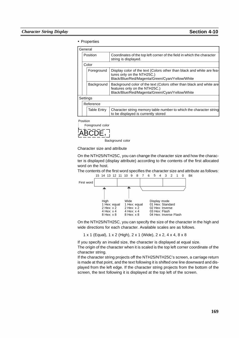
169
Character String Display Section 4-10
! Properties
General
Position Coordinates of the top left corner of the field in which the characterstring is displayed.
Color
Foreground Display color of the text (Colors other than black and white are fea-tures only on the NTH25C.)Black/Blue/Red/Magenta/Green/Cyan/Yellow/White
Background Background color of the text (Colors other than black and white arefeatures only on the NTH25C.)Black/Blue/Red/Magenta/Green/Cyan/Yellow/White
Settings
Reference
Table Entry Character string memory table number to which the character stringto be displayed is currently stored
Background color
ABCDE
PositionForeground color
Character size and attribute
On the NTH25/NTH25C, you can change the character size and how the charac-ter is displayed (display attribute) according to the contents of the first allocatedword on the host.The contents of the first word specifies the character size and attribute as follows:
1415 13 12 11 10 9 8 7 Bit6 5 4 3 2 1 0
First word
High Wide Display mode1 Hex: equal 1 Hex: equal 01 Hex: Standard2 Hex: x 2 2 Hex: x 2 02 Hex: Inverse4 Hex: x 4 4 Hex: x 4 03 Hex: Flash8 Hex: x 8 8 Hex: x 8 04 Hex: Inverse Flash
On the NTH25/NTH25C, you can specify the size of the character in the high andwide directions for each character. Available scales are as follows.
1 x 1 (Equal), 1 x 2 (High), 2 x 1 (Wide), 2 x 2, 4 x 4, 8 x 8
If you specify an invalid size, the character is displayed at equal size.The origin of the character when it is scaled is the top left corner coordinate of thecharacter string.If the character string projects off the NTH25/NTH25C’s screen, a carriage returnis made at that point, and the text following it is shifted one line downward and dis-played from the left edge. If the character string projects from the bottom of thescreen, the text following it is displayed at the top left of the screen.
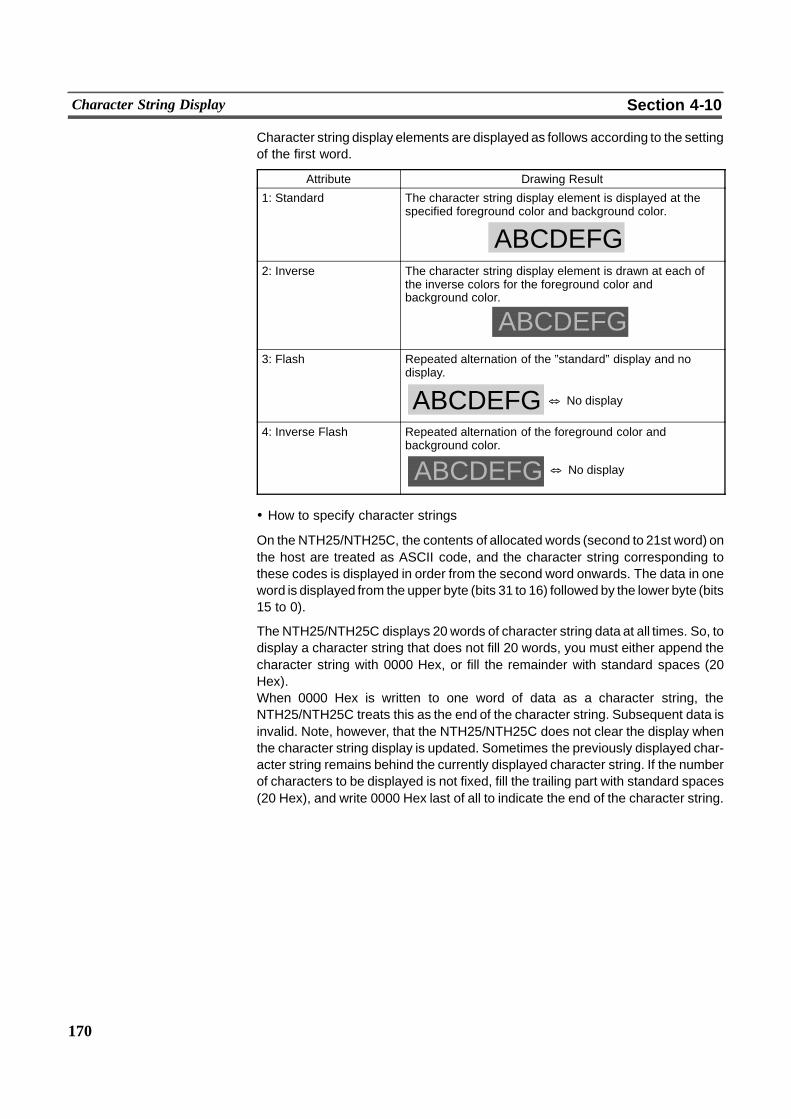
170
Character String Display Section 4-10
Character string display elements are displayed as follows according to the settingof the first word.
Attribute Drawing Result
1: Standard The character string display element is displayed at thespecified foreground color and background color.
ABCDEFG2: Inverse The character string display element is drawn at each of
the inverse colors for the foreground color andbackground color.
ABCDEFG3: Flash Repeated alternation of the ”standard” display and no
display.
& No displayABCDEFG4: Inverse Flash Repeated alternation of the foreground color and
background color.
ABCDEFG & No display
! How to specify character strings
On the NTH25/NTH25C, the contents of allocated words (second to 21st word) onthe host are treated as ASCII code, and the character string corresponding tothese codes is displayed in order from the second word onwards. The data in oneword is displayed from the upper byte (bits 31 to 16) followed by the lower byte (bits15 to 0).
The NTH25/NTH25C displays 20 words of character string data at all times. So, todisplay a character string that does not fill 20 words, you must either append thecharacter string with 0000 Hex, or fill the remainder with standard spaces (20Hex).When 0000 Hex is written to one word of data as a character string, theNTH25/NTH25C treats this as the end of the character string. Subsequent data isinvalid. Note, however, that the NTH25/NTH25C does not clear the display whenthe character string display is updated. Sometimes the previously displayed char-acter string remains behind the currently displayed character string. If the numberof characters to be displayed is not fixed, fill the trailing part with standard spaces(20 Hex), and write 0000 Hex last of all to indicate the end of the character string.
171
Character String Display Section 4-10
[Display Functions]
In the character string display, the character string is displayed in accordance withthe ”General” settings.For details on the display mode according to the ”General” settings, see ”CommonAttributes” (page 173).
[Input Functions]
Character string displays do not have a direct input function as they display thecontents of words on the host via character string memory tables. Note, however,that the NTH25/NTH25C does not actually have character string memory tables,so actually the character string display reads the contents of words on the host.
[Output Functions]
Character string displays have no output function.
[Processing Functions]
Character string displays have no processing function.
[Relationship with Other Elements]
- Character string displays overlap other elements in accordance with the orderin which they were registered to the screen using the Support Tool. Note, how-ever, that you can change the way in which they overlap using the SupportTool.
172
Graphs Section 4-11
4-11 GraphsThe following two types of graphs can be usedwith theNTH25/NTH25C. The con-tents of numeral memory tables (words on the host) are automatically read, andthe graph display is updated.-- Bar graphs See below-- Trend graphs Page 176
4-11-1 Bar Graphs[Function Outline]
The contents of a numeral memory table (words on the host) are displayed in theform of a bar graph.The numeral can also be indicated as a percentage of the specified numeral.
(The frame is not displayed on the NTH25/NTH25C.)
[Restrictions]
- The maximum number of bar graph elements that can be registered to onescreen varies as follows according to the communications method:[Host link, NT link (1:1)]Max. 30The number of bar graph elements is counted according to their display order,and elements exceeding this maximum are discarded. Normally, the displayorder is the order in which elements were created. This order can be changedusing the Support Tool.[Memory link]Max. 30Bar graphs are counted in order from the smallest numeralmemory table num-ber. Bar graphs exceeding this maximum are discarded.
- Bar graph elements in the same screen cannot reference the same numeralmemory table. If there are two or more bar graph elements to which the samenumeralmemory table is set in the same screen, the element having the small-est display number is valid. Normally, the display order is the order in whichelements were created. This order can be changed using the Support Tool.
- There is no restriction on the number of bar graphs that can be registered toone screen data file; any number can be registered as long as the maximumdata file size is not exceeded.
- On the NTH25/NTH25C, the contents of the words on the host are recognizedaccording to the settingmade for ”Numeral Storage Type” (BCD/binary) for thenumeral memory table. For details, see ”Word contents and display numerals”page 163. Note, however, that the number of referenced words for bar graphsis fixed to one.
- On the NTH25/NTH25C, the number of words that are referenced for display-ing bar graphs is fixed to one.
- Bar graphs cannot specify numeral memory tables indirectly. Direct referenc-ing must be used.
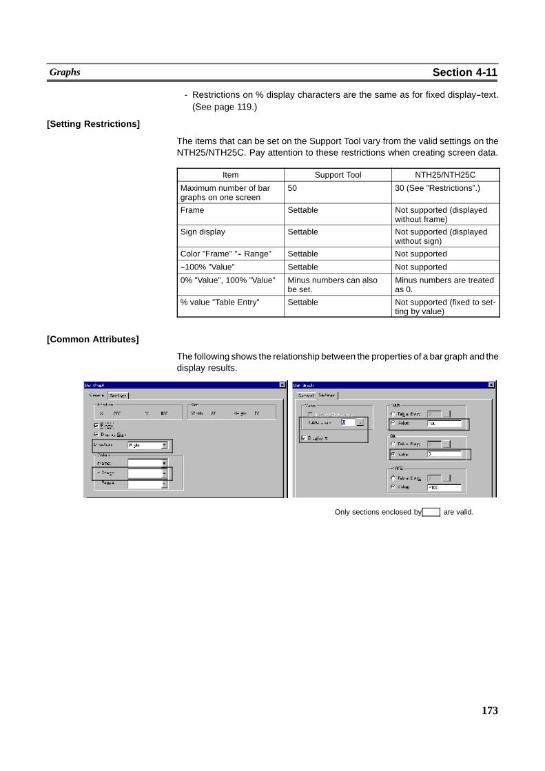
173
Graphs Section 4-11
- Restrictions on % display characters are the same as for fixed display--text.(See page 119.)
[Setting Restrictions]
The items that can be set on the Support Tool vary from the valid settings on theNTH25/NTH25C. Pay attention to these restrictions when creating screen data.
Item Support Tool NTH25/NTH25C
Maximum number of bargraphs on one screen
50 30 (See ”Restrictions”.)
Frame Settable Not supported (displayedwithout frame)
Sign display Settable Not supported (displayedwithout sign)
Color ”Frame” ”-- Range” Settable Not supported
--100% ”Value” Settable Not supported
0% ”Value”, 100% ”Value” Minus numbers can alsobe set.
Minus numbers are treatedas 0.
% value ”Table Entry” Settable Not supported (fixed to set-ting by value)
[Common Attributes]
The following shows the relationship between the properties of a bar graph and thedisplay results.
Only sections enclosed by are valid.
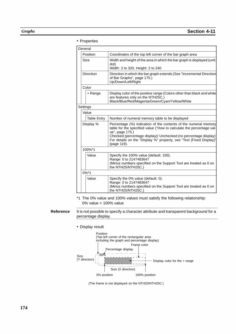
174
Graphs Section 4-11
! Properties
General
Position Coordinates of the top left corner of the bar graph area
Size Width and height of the area inwhich the bar graph is displayed (unit:dot)Width: 2 to 320, Height: 2 to 240
Direction Direction in which the bar graph extends (See ”Incremental Directionof Bar Graphs”, page 175.)Up/Down/Left/Right
Color
+ Range Display color of the positive range (Colors other than black andwhiteare features only on the NTH25C.)Black/Blue/Red/Magenta/Green/Cyan/Yellow/White
Settings
Value
Table Entry Number of numeral memory table to be displayed
Display % Percentage (%) indication of the contents of the numeral memorytable for the specified value (”How to calculate the percentage val-ue”, page 175.)Checked (percentage display)/ Unchecked (no percentage display)For details on the ”Display %” property, see ”Text (Fixed Display)”(page 119).
100%*1
Value Specify the 100% value (default: 100).Range: 0 to 2147483647(Minus numbers specified on the Support Tool are treated as 0 onthe NTH25/NTH25C.)
0%*1
Value Specify the 0% value (default: 0).Range: 0 to 2147483647(Minus numbers specified on the Support Tool are treated as 0 onthe NTH25/NTH25C.)
*1 The 0% value and 100% values must satisfy the following relationship:0% value < 100% value
Reference It is not possible to specify a character attribute and transparent background for apercentage display.
! Display result
60%
100% position
Position(Top left corner of the rectangular areaincluding the graph and percentage display)
Percentage display
Display color for the + range
Frame color
Size(Y direction)
0% position
Size (X direction)
(The frame is not displayed on the NTH25/NTH25C.)
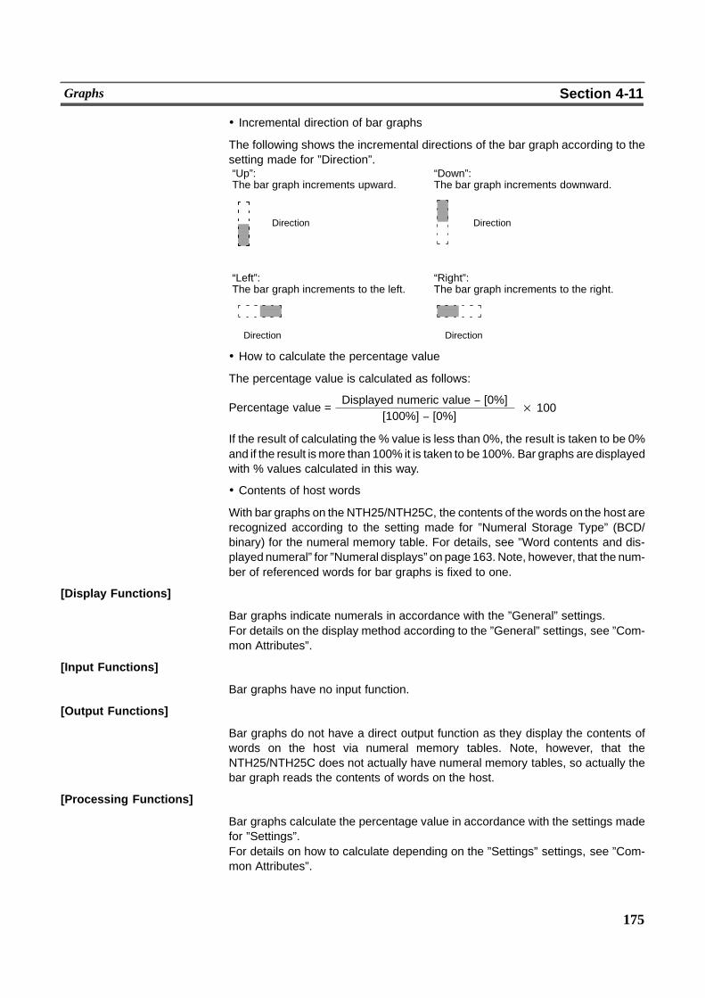
175
Graphs Section 4-11
! Incremental direction of bar graphs
The following shows the incremental directions of the bar graph according to thesetting made for ”Direction”.
� �
� �
“Up”: “Down”:The bar graph increments upward. The bar graph increments downward.
“Left”: “Right”:The bar graph increments to the left. The bar graph increments to the right.
Direction Direction
Direction Direction
! How to calculate the percentage value
The percentage value is calculated as follows:
Percentage value =[100%] ( [0%]
Displayed numeric value ( [0%]× 100
If the result of calculating the % value is less than 0%, the result is taken to be 0%and if the result ismore than 100% it is taken to be 100%. Bar graphs are displayedwith % values calculated in this way.
! Contents of host words
With bar graphs on the NTH25/NTH25C, the contents of thewords on the host arerecognized according to the setting made for ”Numeral Storage Type” (BCD/binary) for the numeral memory table. For details, see ”Word contents and dis-played numeral” for ”Numeral displays” on page 163. Note, however, that the num-ber of referenced words for bar graphs is fixed to one.
[Display Functions]
Bar graphs indicate numerals in accordance with the ”General” settings.For details on the display method according to the ”General” settings, see ”Com-mon Attributes”.
[Input Functions]
Bar graphs have no input function.
[Output Functions]
Bar graphs do not have a direct output function as they display the contents ofwords on the host via numeral memory tables. Note, however, that theNTH25/NTH25C does not actually have numeral memory tables, so actually thebar graph reads the contents of words on the host.
[Processing Functions]
Bar graphs calculate the percentage value in accordance with the settings madefor ”Settings”.For details on how to calculate depending on the ”Settings” settings, see ”Com-mon Attributes”.
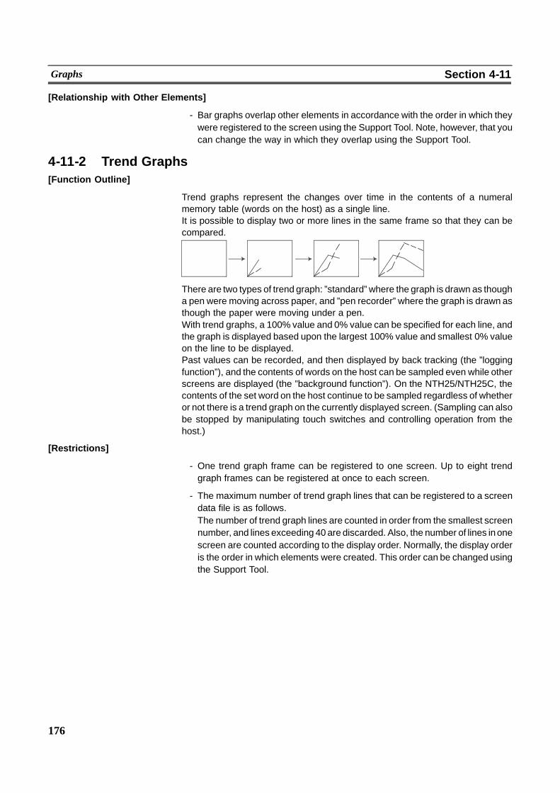
176
Graphs Section 4-11
[Relationship with Other Elements]
- Bar graphs overlap other elements in accordance with the order in which theywere registered to the screen using the Support Tool. Note, however, that youcan change the way in which they overlap using the Support Tool.
4-11-2 Trend Graphs[Function Outline]
Trend graphs represent the changes over time in the contents of a numeralmemory table (words on the host) as a single line.It is possible to display two or more lines in the same frame so that they can becompared.
There are two types of trend graph: ”standard” where the graph is drawn as thougha pen were moving across paper, and ”pen recorder” where the graph is drawn asthough the paper were moving under a pen.With trend graphs, a 100% value and 0% value can be specified for each line, andthe graph is displayed based upon the largest 100% value and smallest 0% valueon the line to be displayed.Past values can be recorded, and then displayed by back tracking (the ”loggingfunction”), and the contents of words on the host can be sampled even while otherscreens are displayed (the ”background function”). On the NTH25/NTH25C, thecontents of the set word on the host continue to be sampled regardless of whetheror not there is a trend graph on the currently displayed screen. (Sampling can alsobe stopped by manipulating touch switches and controlling operation from thehost.)
[Restrictions]
- One trend graph frame can be registered to one screen. Up to eight trendgraph frames can be registered at once to each screen.
- The maximum number of trend graph lines that can be registered to a screendata file is as follows.The number of trend graph lines are counted in order from the smallest screennumber, and lines exceeding 40 are discarded. Also, the number of lines inonescreen are counted according to the display order. Normally, the display orderis the order in which elements were created. This order can be changed usingthe Support Tool.
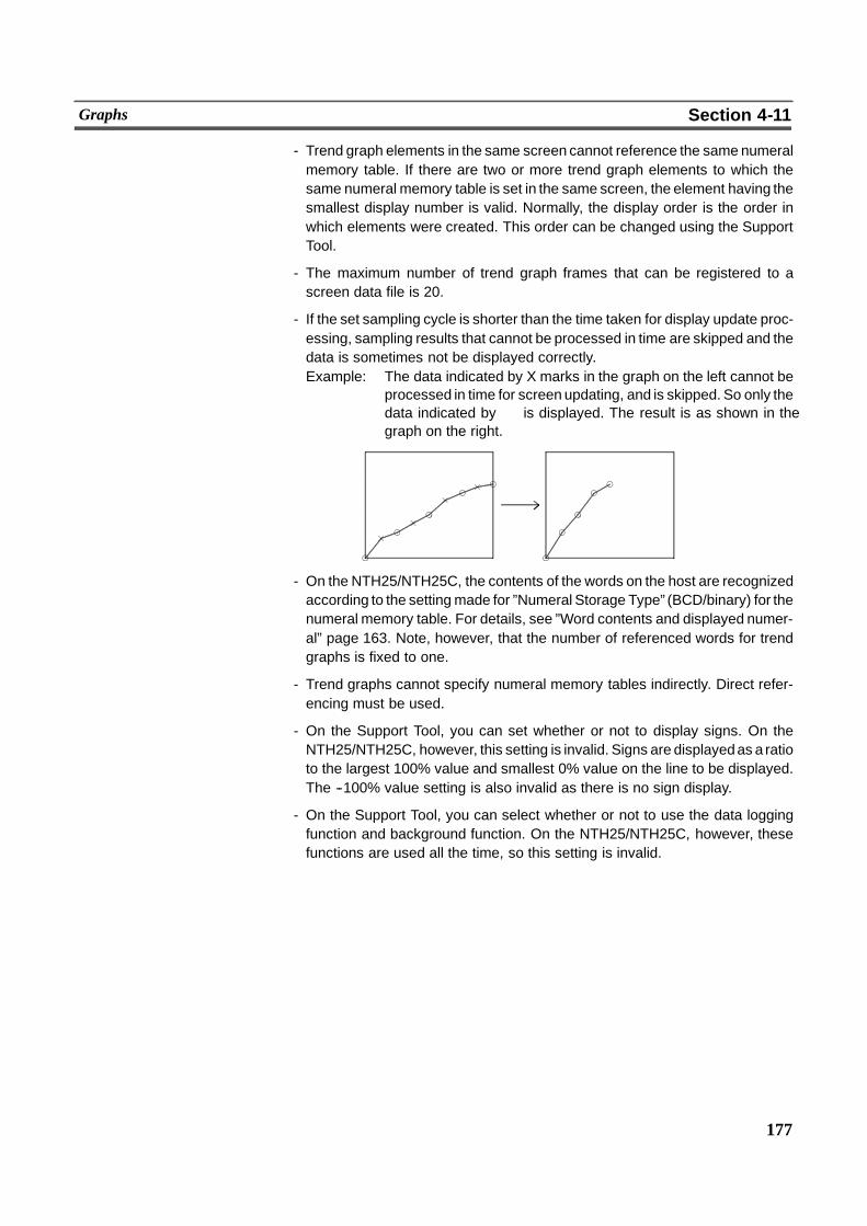
177
Graphs Section 4-11
- Trend graph elements in the same screen cannot reference the same numeralmemory table. If there are two or more trend graph elements to which thesame numeral memory table is set in the same screen, the element having thesmallest display number is valid. Normally, the display order is the order inwhich elements were created. This order can be changed using the SupportTool.
- The maximum number of trend graph frames that can be registered to ascreen data file is 20.
- If the set sampling cycle is shorter than the time taken for display update proc-essing, sampling results that cannot be processed in time are skipped and thedata is sometimes not be displayed correctly.Example: The data indicated by X marks in the graph on the left cannot be
processed in time for screen updating, and is skipped. So only thedata indicated by � is displayed. The result is as shown in thegraph on the right.
- On the NTH25/NTH25C, the contents of the words on the host are recognizedaccording to the settingmade for ”Numeral Storage Type” (BCD/binary) for thenumeral memory table. For details, see ”Word contents and displayed numer-al” page 163. Note, however, that the number of referenced words for trendgraphs is fixed to one.
- Trend graphs cannot specify numeral memory tables indirectly. Direct refer-encing must be used.
- On the Support Tool, you can set whether or not to display signs. On theNTH25/NTH25C, however, this setting is invalid. Signs are displayedas a ratioto the largest 100% value and smallest 0% value on the line to be displayed.The --100% value setting is also invalid as there is no sign display.
- On the Support Tool, you can select whether or not to use the data loggingfunction and background function. On the NTH25/NTH25C, however, thesefunctions are used all the time, so this setting is invalid.
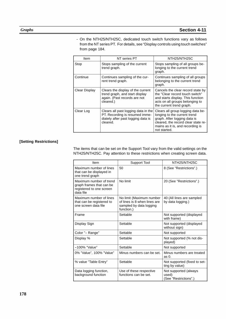
178
Graphs Section 4-11
- On the NTH25/NTH25C, dedicated touch switch functions vary as followsfrom theNT series PT. For details, see “Display controls using touch switches”from page 184.
Item NT series PT NTH25/NTH25C
Stop Stops sampling of the currenttrend graph.
Stops sampling of all groups be-longing to the current trendgraph.
Continue Continues sampling of the cur-rent trend graph.
Continues sampling of all groupsbelonging to the current trendgraph.
Clear Display Clears the display of the currenttrend graph, and start displayagain. (Past records are notcleared.)
Cancels the clear record state bythe ”Clear record touch switch”and starts display. This functionacts on all groups belonging tothe current trend graph.
Clear Log Clears all past logging data in thePT. Recording is resumed imme-diately after past logging data iscleared.
Clears all group logging data be-longing to the current trendgraph. After logging data iscleared, the record clear state re-mains as it is, and recording isnot started.
[Setting Restrictions]
The items that can be set on the Support Tool vary from the valid settings on theNTH25/NTH25C. Pay attention to these restrictions when creating screen data.
Item Support Tool NTH25/NTH25C
Maximum number of linesthat can be displayed inone trend graph
50 8 (See ”Restrictions”.)
Maximum number of trendgraph frames that can beregistered to one screendata file
No limit 20 (See ”Restrictions”.)
Maximum number of linesthat can be registered toone screen data file
No limit (Maximum numberof lines is 8 when lines aresampled by data loggingfunction.)
40 (All lines are sampledby data logging.)
Frame Settable Not supported (displayedwith frame)
Display Sign Settable Not supported (displayedwithout sign)
Color ”-- Range” Settable Not supported
Display % Settable Not supported (% not dis-played)
--100% ”Value” Settable Not supported
0% ”Value”, 100% ”Value” Minus numbers can be set. Minus numbers are treatedas 0.
% value ”Table Entry” Settable Not supported (fixed to set-ting by value)
Data logging function,background function
Use of these respectivefunctions can be set.
Not supported (alwaysused)(See ”Restrictions”.)
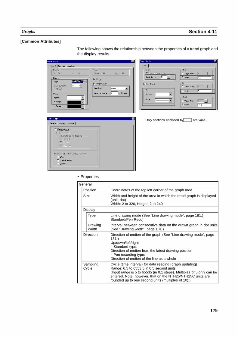
179
Graphs Section 4-11
[Common Attributes]
The following shows the relationship between the properties of a trend graph andthe display results.
Only sections enclosed by are valid.
! Properties
General
Position Coordinates of the top left corner of the graph area
Size Width and height of the area in which the trend graph is displayed(unit: dot)Width: 2 to 320, Height: 2 to 240
Display
Type Line drawing mode (See ”Line drawing mode”, page 181.)Standard/Pen Reco)
DrawingWidth
Interval between consecutive data on the drawn graph in dot units(See ”Drawing width”, page 181.)
Direction Direction of motion of the graph (See ”Line drawing mode”, page181.)Up/down/left/right-- Standard type:Direction of motion from the latest drawing position-- Pen recording type:Direction of motion of the line as a whole
SamplingCycle
Cycle (time interval) for data reading (graph updating)Range: 0.5 to 6553.5 in 0.5 second units(Input range is 5 to 65535 (in 0.1 steps). Multiples of 5 only can beentered. Note, however, that on the NTH25/NTH25C units arerounded up to one second units (multiples of 10).)
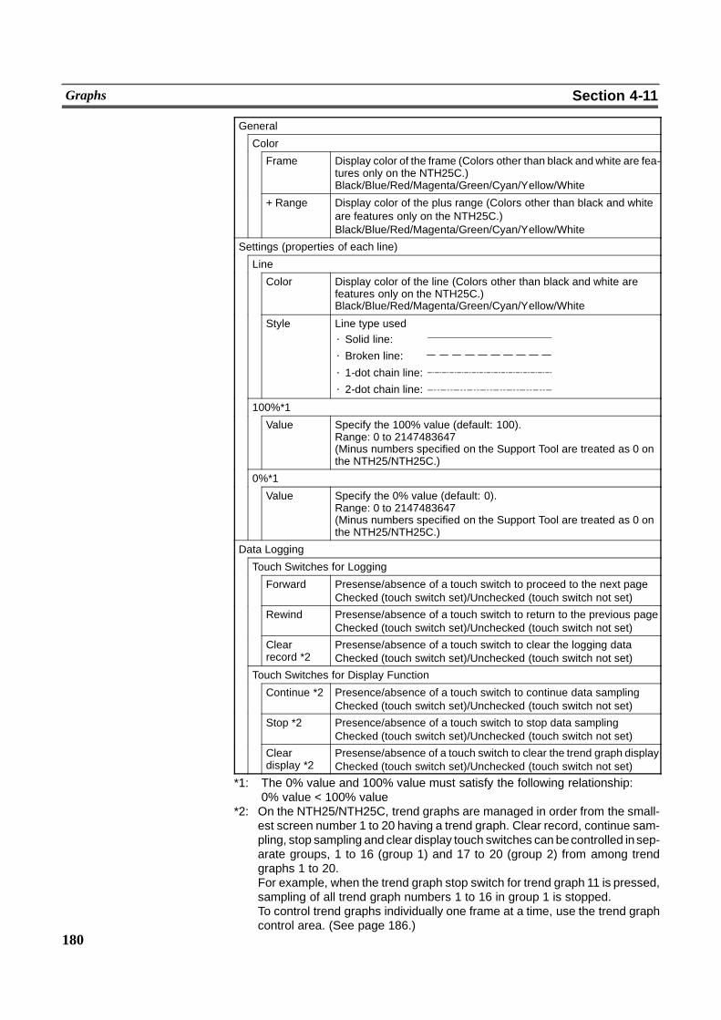
180
Graphs Section 4-11
General
Color
Frame Display color of the frame (Colors other than black andwhite are fea-tures only on the NTH25C.)Black/Blue/Red/Magenta/Green/Cyan/Yellow/White
+ Range Display color of the plus range (Colors other than black and whiteare features only on the NTH25C.)Black/Blue/Red/Magenta/Green/Cyan/Yellow/White
Settings (properties of each line)
Line
Color Display color of the line (Colors other than black and white arefeatures only on the NTH25C.)Black/Blue/Red/Magenta/Green/Cyan/Yellow/White
Style Line type used⋅ Solid line:
⋅ Broken line:
⋅ 1-dot chain line:
⋅ 2-dot chain line:
100%*1
Value Specify the 100% value (default: 100).Range: 0 to 2147483647(Minus numbers specified on the Support Tool are treated as 0 onthe NTH25/NTH25C.)
0%*1
Value Specify the 0% value (default: 0).Range: 0 to 2147483647(Minus numbers specified on the Support Tool are treated as 0 onthe NTH25/NTH25C.)
Data Logging
Touch Switches for Logging
Forward Presense/absence of a touch switch to proceed to the next pageChecked (touch switch set)/Unchecked (touch switch not set)
Rewind Presense/absence of a touch switch to return to the previous pageChecked (touch switch set)/Unchecked (touch switch not set)
Clearrecord *2
Presense/absence of a touch switch to clear the logging dataChecked (touch switch set)/Unchecked (touch switch not set)
Touch Switches for Display Function
Continue *2 Presence/absence of a touch switch to continue data samplingChecked (touch switch set)/Unchecked (touch switch not set)
Stop *2 Presence/absence of a touch switch to stop data samplingChecked (touch switch set)/Unchecked (touch switch not set)
Cleardisplay *2
Presense/absence of a touch switch to clear the trend graph displayChecked (touch switch set)/Unchecked (touch switch not set)
*1: The 0% value and 100% value must satisfy the following relationship:0% value < 100% value
*2: On the NTH25/NTH25C, trend graphs are managed in order from the small-est screen number 1 to 20 having a trend graph. Clear record, continue sam-pling, stop sampling and clear display touch switches can becontrolled insep-arate groups, 1 to 16 (group 1) and 17 to 20 (group 2) from among trendgraphs 1 to 20.For example, when the trend graph stop switch for trend graph 11 is pressed,sampling of all trend graph numbers 1 to 16 in group 1 is stopped.To control trend graphs individually one frame at a time, use the trend graphcontrol area. (See page 186.)
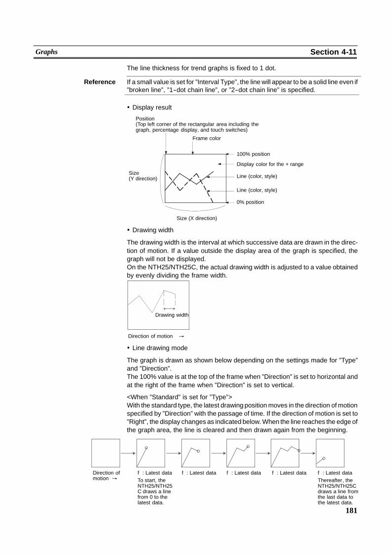
181
Graphs Section 4-11
The line thickness for trend graphs is fixed to 1 dot.
Reference If a small value is set for ”Interval Type”, the linewill appear to be a solid line even if”broken line”, ”1--dot chain line”, or ”2--dot chain line” is specified.
! Display result
Size (X direction)
Position(Top left corner of the rectangular area including thegraph, percentage display, and touch switches)
Frame color
100% position
Display color for the + range
Size(Y direction)
Line (color, style)
0% position
Line (color, style)
! Drawing width
The drawing width is the interval at which successive data are drawn in the direc-tion of motion. If a value outside the display area of the graph is specified, thegraph will not be displayed.On the NTH25/NTH25C, the actual drawing width is adjusted to a value obtainedby evenly dividing the frame width.
Direction of motion %
Drawing width
! Line drawing mode
The graph is drawn as shown below depending on the settings made for ”Type”and ”Direction”.The 100% value is at the top of the frame when ”Direction” is set to horizontal andat the right of the frame when ”Direction” is set to vertical.
<When ”Standard” is set for ”Type”>With the standard type, the latest drawing positionmoves in the direction ofmotionspecified by ”Direction” with the passage of time. If the direction of motion is set to”Right”, the display changes as indicated below.When the line reaches the edge ofthe graph area, the line is cleared and then drawn again from the beginning.
Direction ofmotion %
f: Latest dataTo start, theNTH25/NTH25C draws a linefrom 0 to thelatest data.
f: Latest data f: Latest data f: Latest data f: Latest dataThereafter, theNTH25/NTH25Cdraws a line fromthe last data tothe latest data.
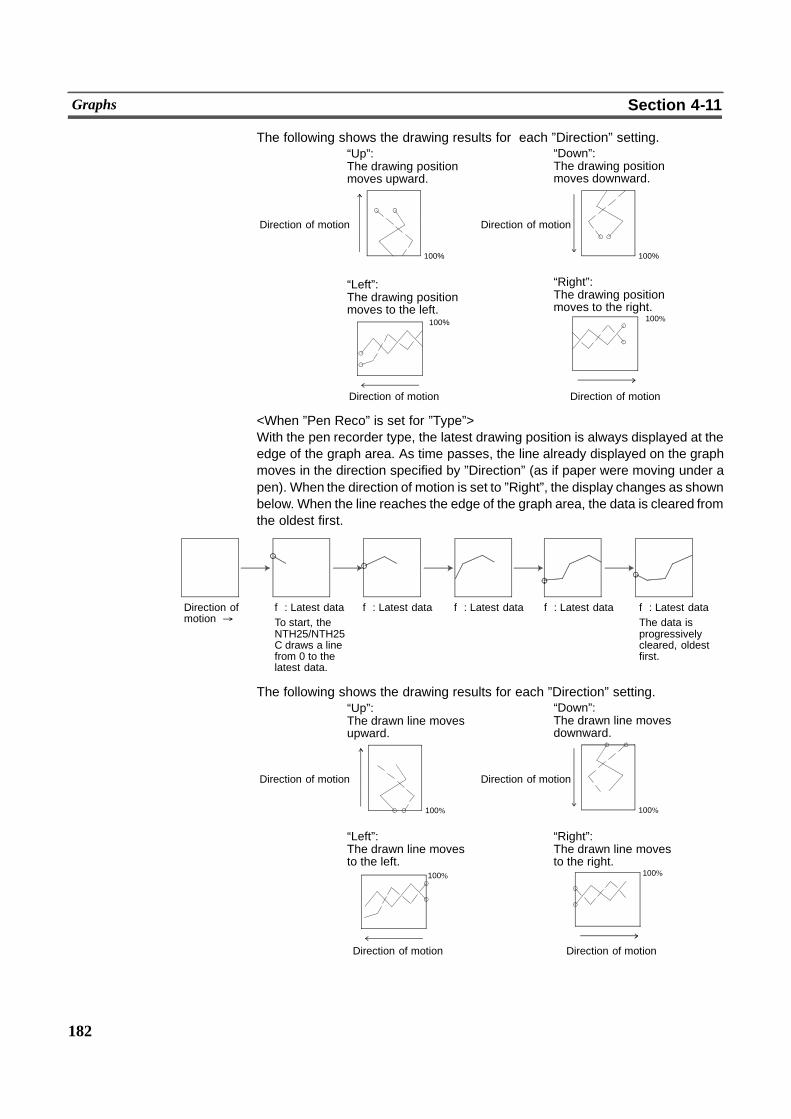
182
Graphs Section 4-11
The following shows the drawing results for each ”Direction” setting.“Up”:The drawing positionmoves upward.
Direction of motion
“Down”:The drawing positionmoves downward.
Direction of motion
“Left”:The drawing positionmoves to the left.
“Right”:The drawing positionmoves to the right.
Direction of motion
Direction of motion
100% 100%
100% 100%
<When ”Pen Reco” is set for ”Type”>With the pen recorder type, the latest drawing position is always displayed at theedge of the graph area. As time passes, the line already displayed on the graphmoves in the direction specified by ”Direction” (as if paper were moving under apen). When the direction of motion is set to ”Right”, the display changes as shownbelow. When the line reaches the edge of the graph area, the data is cleared fromthe oldest first.
Direction ofmotion %
f: Latest dataTo start, theNTH25/NTH25C draws a linefrom 0 to thelatest data.
f: Latest data f: Latest data f: Latest data f: Latest dataThe data isprogressivelycleared, oldestfirst.
The following shows the drawing results for each ”Direction” setting.“Up”:The drawn line movesupward.
Direction of motion
“Down”:The drawn line movesdownward.
Direction of motion
“Left”:The drawn line movesto the left.
“Right”:The drawn line movesto the right.
Direction of motion
Direction of motion
100% 100%
100% 100%
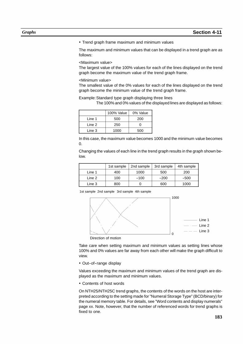
183
Graphs Section 4-11
! Trend graph frame maximum and minimum values
The maximum and minimum values that can be displayed in a trend graph are asfollows:
<Maximum value>The largest value of the 100% values for each of the lines displayed on the trendgraph become the maximum value of the trend graph frame.
<Minimum value>The smallest value of the 0% values for each of the lines displayed on the trendgraph become the minimum value of the trend graph frame.
Example:Standard type graph displaying three linesThe 100%and 0%values of the displayed lines are displayed as follows:
100% Value 0% Value
Line 1 500 200
Line 2 250 0
Line 3 1000 500
In this case, the maximum value becomes 1000 and theminimum value becomes0.
Changing the values of each line in the trend graph results in the graph shown be-low.
1st sample 2nd sample 3rd sample 4th sample
Line 1 400 1000 500 200
Line 2 100 --100 --200 --500
Line 3 800 0 600 1000
Direction of motion�0
1000
1st sample�
2nd sample�
3rd sample�
4th sample�
Line 1
Line 2Line 3
Take care when setting maximum and minimum values as setting lines whose100% and 0% values are far away from each other will make the graph difficult toview.
! Out--of--range display
Values exceeding the maximum and minimum values of the trend graph are dis-played as the maximum and minimum values.
! Contents of host words
On NTH25/NTH25C trend graphs, the contents of the words on the host are inter-preted according to the setting made for ”Numeral Storage Type” (BCD/binary) forthe numeral memory table. For details, see ”Word contents and display numerals”page xx. Note, however, that the number of referenced words for trend graphs isfixed to one.
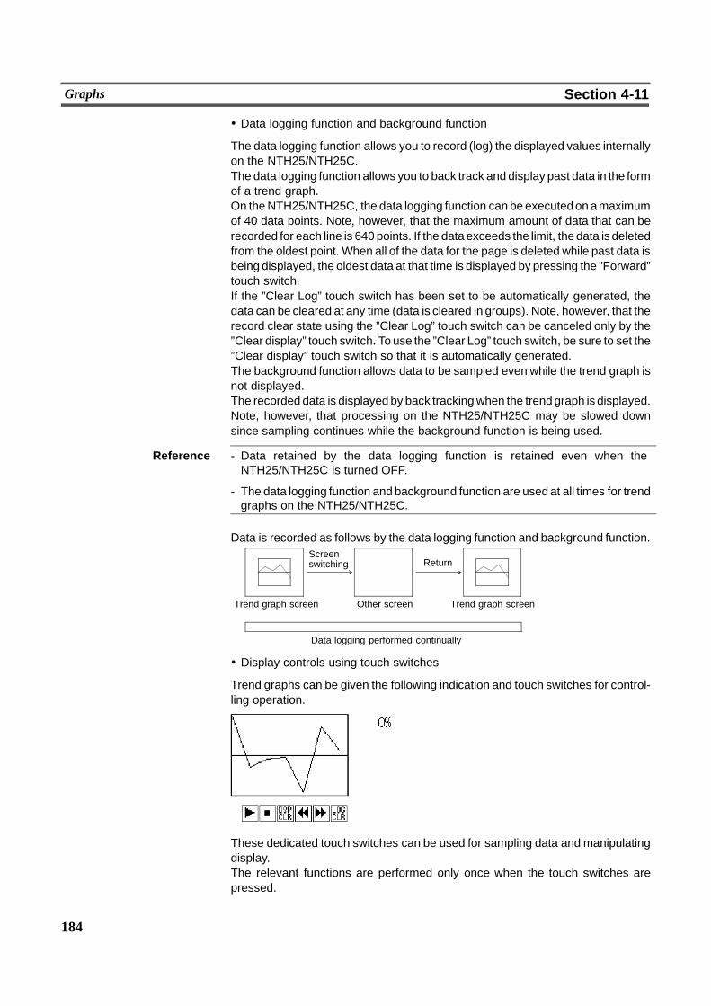
184
Graphs Section 4-11
! Data logging function and background function
The data logging function allows you to record (log) the displayed values internallyon the NTH25/NTH25C.The data logging function allows you to back track and display past data in the formof a trend graph.On theNTH25/NTH25C, the data logging function can be executedon amaximumof 40 data points. Note, however, that the maximum amount of data that can berecorded for each line is 640 points. If the dataexceeds the limit, thedata is deletedfrom the oldest point. When all of the data for the page is deleted while past data isbeing displayed, the oldest data at that time is displayed by pressing the ”Forward”touch switch.If the ”Clear Log” touch switch has been set to be automatically generated, thedata can be cleared at any time (data is cleared in groups). Note, however, that therecord clear state using the ”Clear Log” touch switch can be canceled only by the”Clear display” touch switch. To use the ”Clear Log” touch switch, be sure to set the”Clear display” touch switch so that it is automatically generated.The background function allows data to be sampled even while the trend graph isnot displayed.The recorded data is displayed by back trackingwhen the trendgraph is displayed.Note, however, that processing on the NTH25/NTH25C may be slowed downsince sampling continues while the background function is being used.
Reference - Data retained by the data logging function is retained even when theNTH25/NTH25C is turned OFF.
- The data logging function and background function are used at all times for trendgraphs on the NTH25/NTH25C.
Data is recorded as follows by the data logging function and background function.
Data logging performed continually
Trend graph screen
Screenswitching
Other screen
Return
Trend graph screen
! Display controls using touch switches
Trend graphs can be given the following indication and touch switches for control-ling operation.
These dedicated touch switches can be used for sampling data and manipulatingdisplay.The relevant functions are performed only once when the touch switches arepressed.
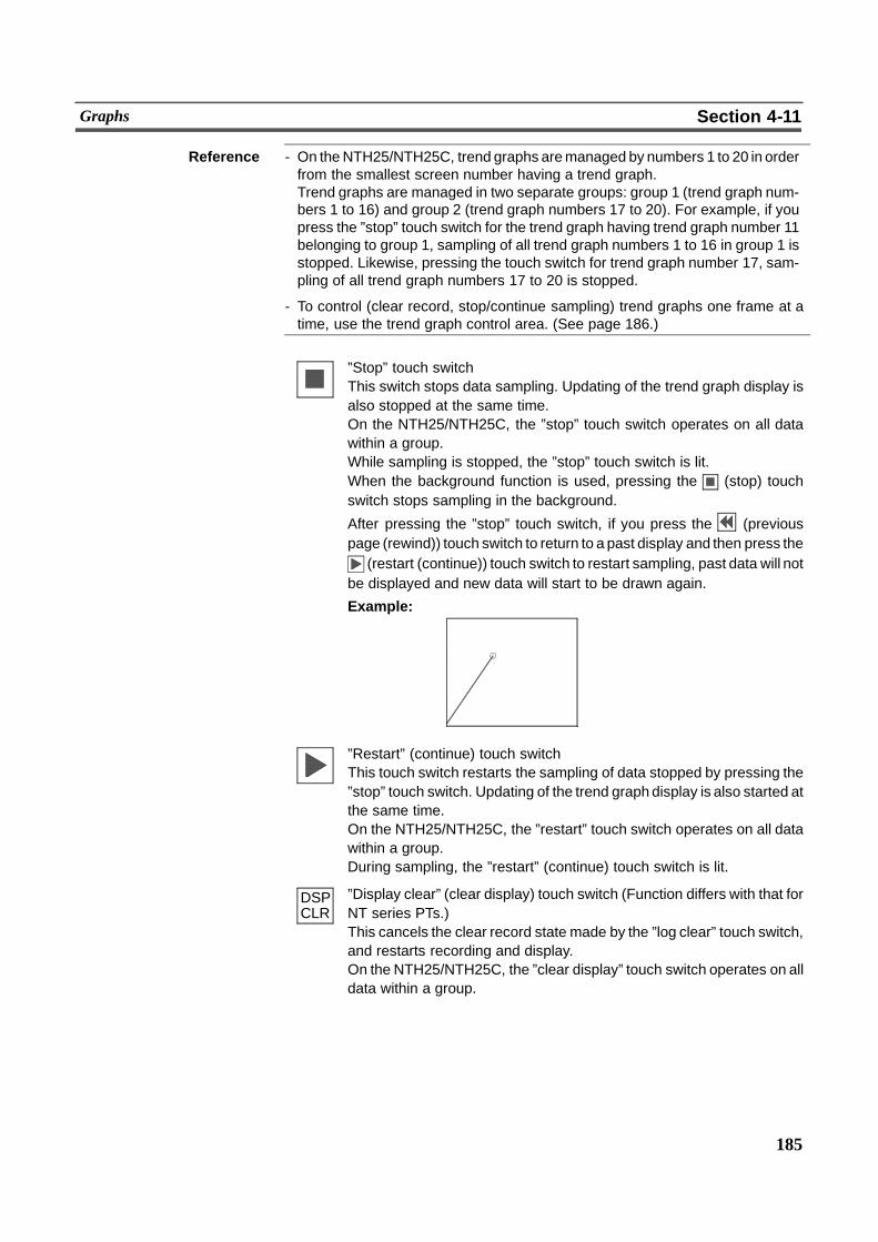
DSPCLR
185
Graphs Section 4-11
Reference - On theNTH25/NTH25C, trend graphs aremanaged by numbers 1 to 20 in orderfrom the smallest screen number having a trend graph.Trend graphs are managed in two separate groups: group 1 (trend graph num-bers 1 to 16) and group 2 (trend graph numbers 17 to 20). For example, if youpress the ”stop” touch switch for the trend graph having trend graph number 11belonging to group 1, sampling of all trend graph numbers 1 to 16 in group 1 isstopped. Likewise, pressing the touch switch for trend graph number 17, sam-pling of all trend graph numbers 17 to 20 is stopped.
- To control (clear record, stop/continue sampling) trend graphs one frame at atime, use the trend graph control area. (See page 186.)
”Stop” touch switchThis switch stops data sampling. Updating of the trend graph display isalso stopped at the same time.On the NTH25/NTH25C, the ”stop” touch switch operates on all datawithin a group.While sampling is stopped, the ”stop” touch switch is lit.When the background function is used, pressing the (stop) touchswitch stops sampling in the background.
After pressing the ”stop” touch switch, if you press the (previouspage (rewind)) touch switch to return to a past display and then press the
(restart (continue)) touch switch to restart sampling, past data will notbe displayed and new data will start to be drawn again.
Example:
”Restart” (continue) touch switchThis touch switch restarts the sampling of data stopped by pressing the”stop” touch switch. Updating of the trend graph display is also started atthe same time.On the NTH25/NTH25C, the ”restart” touch switch operates on all datawithin a group.During sampling, the ”restart” (continue) touch switch is lit.
”Display clear” (clear display) touch switch (Function differs with that forNT series PTs.)This cancels the clear record state made by the ”log clear” touch switch,and restarts recording and display.On the NTH25/NTH25C, the ”clear display” touch switch operates on alldata within a group.
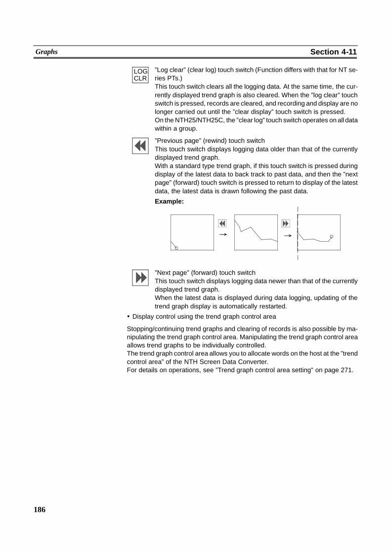
LOGCLR
186
Graphs Section 4-11
”Log clear” (clear log) touch switch (Function differs with that for NT se-ries PTs.)This touch switch clears all the logging data. At the same time, the cur-rently displayed trend graph is also cleared. When the ”log clear” touchswitch is pressed, records are cleared, and recording and display are nolonger carried out until the ”clear display” touch switch is pressed.On theNTH25/NTH25C, the ”clear log” touch switch operates on all datawithin a group.
”Previous page” (rewind) touch switchThis touch switch displays logging data older than that of the currentlydisplayed trend graph.With a standard type trend graph, if this touch switch is pressed duringdisplay of the latest data to back track to past data, and then the ”nextpage” (forward) touch switch is pressed to return to display of the latestdata, the latest data is drawn following the past data.
Example:
% %
”Next page” (forward) touch switchThis touch switch displays logging data newer than that of the currentlydisplayed trend graph.When the latest data is displayed during data logging, updating of thetrend graph display is automatically restarted.
! Display control using the trend graph control area
Stopping/continuing trend graphs and clearing of records is also possible by ma-nipulating the trend graph control area. Manipulating the trend graph control areaallows trend graphs to be individually controlled.The trend graph control area allows you to allocate words on the host at the ”trendcontrol area” of the NTH Screen Data Converter.For details on operations, see ”Trend graph control area setting” on page 271.
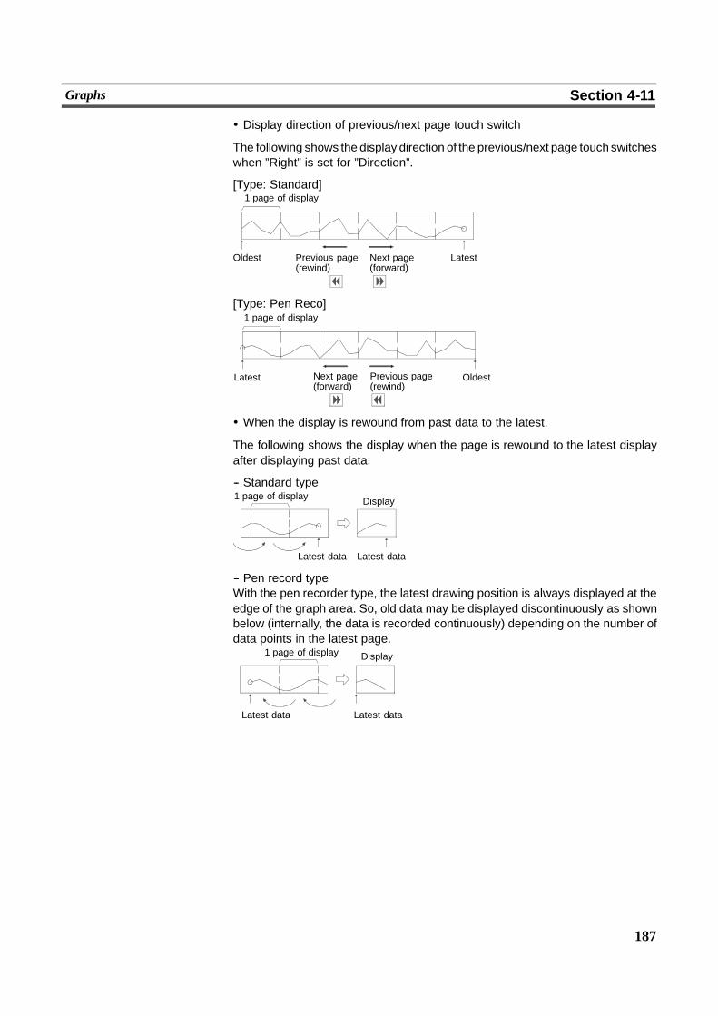
187
Graphs Section 4-11
! Display direction of previous/next page touch switch
The following shows the display direction of the previous/next page touchswitcheswhen ”Right” is set for ”Direction”.
[Type: Standard]1 page of display
Oldest Previous page(rewind)
Next page(forward)
Latest
[Type: Pen Reco]1 page of display
OldestLatest Previous page(rewind)
Next page(forward)
! When the display is rewound from past data to the latest.
The following shows the display when the page is rewound to the latest displayafter displaying past data.
-- Standard type1 page of display
Latest data Latest data
Display
-- Pen record typeWith the pen recorder type, the latest drawing position is always displayed at theedge of the graph area. So, old data may be displayed discontinuously as shownbelow (internally, the data is recorded continuously) depending on the number ofdata points in the latest page.
Latest data
1 page of display
Latest data
Display
188
Graphs Section 4-11
[Display Functions]
- With trend graphs, the graph area is displayed in accordance with the ”Gener-al” settings, and the broken line is displayed in accordance with the ”Settings”(properties of each line) settings.For details on the display mode depending on the ”General” and ”Settings”(properties of each line) settings, see ”Common Attributes”.
- When two or more broken line graphs are registered, they are overwritten inthe order in which they were registered. When broken lines overlap, colors aredisplayed in their corresponding inverse color. So, line types and colors mayappear to be different from their specified color. The same applies when bro-ken lines overlap the graph frame.*: Display color and their respective inverse colors are as follows:Black $ White, Blue$ Yellow, Red$ Cyan, Magenta $ Green
[Input Functions]
Trend graphs do not have a direct input function as they display the contents ofwords on the host via numeral memory tables. Note, however, that theNTH25/NTH25C does not actually have numeral memory tables, so actually thetrend graph reads the contents of words on the host.
[Output Functions]
Trend graphs have no output function.
[Processing Functions]
Trend graphs have no data processing function.
[Relationship with Other Elements]
Donot overlap other elements within the area inwhich a trend graph is drawn. Thiscan cause the graph to be displayed incorrectly.
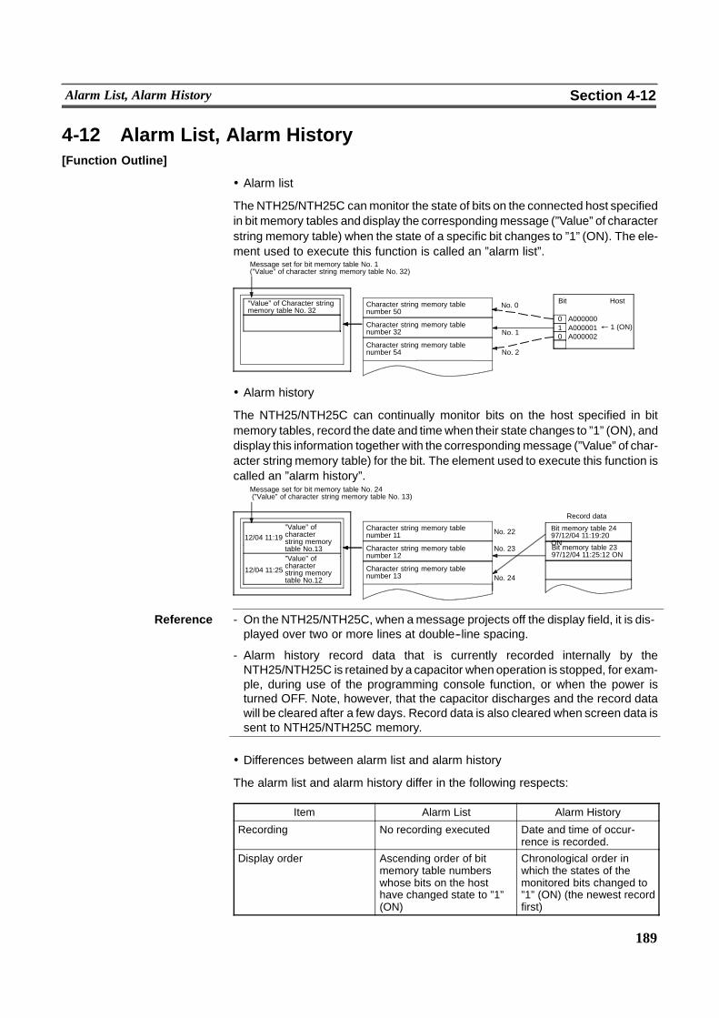
189
Alarm List, Alarm History Section 4-12
4-12 Alarm List, Alarm History[Function Outline]
! Alarm list
The NTH25/NTH25C canmonitor the state of bits on the connected host specifiedin bit memory tables and display the correspondingmessage (”Value” of characterstring memory table) when the state of a specific bit changes to ”1” (ON). The ele-ment used to execute this function is called an ”alarm list”.
“Value” of Character stringmemory table No. 32
Character string memory tablenumber 50
Character string memory tablenumber 32
Character string memory tablenumber 54
BitNo. 0
" 1 (ON)No. 1
No. 2
0 A0000001 A0000010 A000002
Host
Message set for bit memory table No. 1(”Value” of character string memory table No. 32)
! Alarm history
The NTH25/NTH25C can continually monitor bits on the host specified in bitmemory tables, record the date and timewhen their state changes to ”1” (ON), anddisplay this information together with the correspondingmessage (”Value” of char-acter string memory table) for the bit. The element used to execute this function iscalled an ”alarm history”.
Character string memory tablenumber 11
Character string memory tablenumber 12
Character string memory tablenumber 13
No. 22 Bit memory table 2497/12/04 11:19:20ON�Bit memory table 2397/12/04 11:25:12 ON
No. 23
No. 24
Message set for bit memory table No. 24(”Value” of character string memory table No. 13)
”Value” ofcharacterstring memorytable No.13”Value” ofcharacterstring memorytable No.12
Record data
12/04 11:19
12/04 11:25
Reference - On the NTH25/NTH25C, when amessage projects off the display field, it is dis-played over two or more lines at double--line spacing.
- Alarm history record data that is currently recorded internally by theNTH25/NTH25C is retained by a capacitor whenoperation is stopped, for exam-ple, during use of the programming console function, or when the power isturned OFF. Note, however, that the capacitor discharges and the record datawill be cleared after a few days. Record data is also cleared when screen data issent to NTH25/NTH25C memory.
! Differences between alarm list and alarm history
The alarm list and alarm history differ in the following respects:
Item Alarm List Alarm History
Recording No recording executed Date and time of occur-rence is recorded.
Display order Ascending order of bitmemory table numberswhose bits on the hosthave changed state to ”1”(ON)
Chronological order inwhich the states of themonitored bits changed to”1” (ON) (the newest recordfirst)
190
Alarm List, Alarm History Section 4-12
! Outline of alarm list/alarm history operations
The following describes alarm list and alarm history operations.
Reference - The alarm list and alarm history check bits on the host allocated bit memorytables.Consequently, if a large number of host bits is set, processing on theNTH25/NTH25C may be slowed down.
- Alarm lists are displayed in ascending order of bit memory table numbers, andalarm histories are displayed in occurrence order (from the newest record).
- In the case of alarm lists, the message is automatically cleared if the state of ahost bit allocated a bit memory table returns to ”0” (OFF) while an alarm list isdisplayed.In the case of alarm histories, the previous message remains, and a messageindicating that the bit has changed to 0 (OFF) again is displayed if the state of ahost bit allocated a bit memory table returns to 0 (OFF) while an alarm history isdisplayed.Also, the correspondingmessage is displayed if the state of a host bit changes to1 (ON) while an alarm history is displayed.
[Restrictions]
- Only either of an alarm list or alarm history can be registered to a screen.
- An alarm list/alarm history can display up to 8 messages at the same time.Messages which are hidden can be displayed by operating the line or pagescroll touch switches specially provided.
- Themaximum number of data records that can be recorded with the alarm his-tory is 200.
- On the Support Tool, bit memory table numbers and the number of referencedbit memory tables can be set to alarm lists. The NTH25/NTH25C, however,always monitors 240 host bits (15 words) from the PC address (bit) currentlyset to bit memory table number 0. So, the bit memory table numbers and thenumber of referenced bit memory tables settings are invalid. (See ”Bit memorytables” page 103.)
- On the NTH25/NTH25C, messages for alarm lists and alarm histories thatcannot fit on one line are displayed over two or more lines. (If the messageprojects downwards off the screen, the entire message is fed to the nextpage.) Messages spread over two or more lines are displayed at double--linespacing. For this reason, the appearance of messages differs from that on theSupport Tool.Be sure to check the display on the NTH25/NTH25C before use.
191
Alarm List, Alarm History Section 4-12
- On the Support Tool, you can set whether or not to display the date and time ofoccurrence and the display mode. On the NTH25/NTH25C, however, this set-ting is invalid, and the display is always the occurrence order in the format”month/day, hours:minutes”. Set as follows to prevent mismatch with the dis-play on the Support Tool:
History Info: CheckedOrder Type: Occurrence orderInfo Type: Month/day, hours:minutes
On the NTH25/NTH25C, changes in bit states are displayed as follows in additionto the infomation above:
When bit state changes from 0 (OFF) to 1 (ON): Alarm occurrenceWhen bit state changes from 1 (ON) to 0 (OFF): Recovery
- On the Support Tool, the width of themessage display field is ”Length” plus thedate and time of occurrence. (Actually, it is slightly longer as the field is ad-justed to fit the touch switch.) Whereas, on theNTH25/NTH25C, the part up tothe date of occurrence display is included in ”Length” and the display fieldwidth is calculated by adding the message display field on the Support Tool tothe bit change information component (5 digits). So, when ”month/dayhours:minute” display (12 digits) is set, the display on the NTH25/NTH25C isseven digits narrower than on the Support Tool. Arrange elements taking thisinto consideration when creating screens.
Example: When ”Length” is set to 16 and ”month/day hours:minutes” dis-play is set:-- On Support ToolDisplay field width = 16 digits + 12 digits = 28 digits-- On the NTH25/NTH25CDisplay field width = 16 digits + 5 digits = 21 digits
According to the above calculation, only four digits will be used for displayingmessages on the NTH25/NTH25C. To use 16 digits for displaying messages,you must set ”Length” to 28.
- On the NTH25/NTH25C, the alarm history cannot be displayed in the frequen-cy (count) order.
- On the Support Tool, you can set the color ofmessage display field frames andtheir background color when lit. On the NTH25/NTH25C, however, these set-tings are invalid as message display fields do not have a function for acting atouch switch. Display fields are displayed in their OFF color at all times.
- On the Support Tool, you can set whether or not to display image/library dataand their color. On the NTH25/NTH25C, however, image/library data cannotbe displayed in alarm lists and histories, so these settings are invalid.
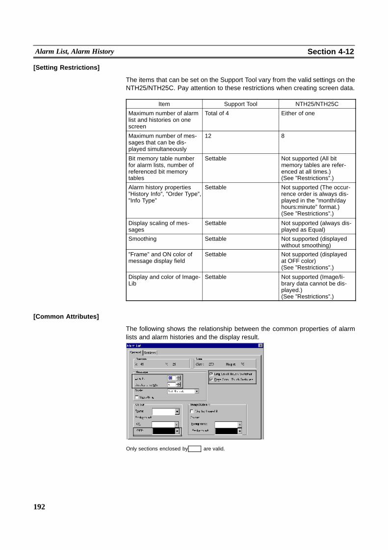
192
Alarm List, Alarm History Section 4-12
[Setting Restrictions]
The items that can be set on the Support Tool vary from the valid settings on theNTH25/NTH25C. Pay attention to these restrictions when creating screen data.
Item Support Tool NTH25/NTH25C
Maximum number of alarmlist and histories on onescreen
Total of 4 Either of one
Maximum number of mes-sages that can be dis-played simultaneously
12 8
Bit memory table numberfor alarm lists, number ofreferenced bit memorytables
Settable Not supported (All bitmemory tables are refer-enced at all times.)(See ”Restrictions”.)
Alarm history properties”History Info”, ”Order Type”,”Info Type”
Settable Not supported (The occur-rence order is always dis-played in the ”month/dayhours:minute” format.)(See ”Restrictions”.)
Display scaling of mes-sages
Settable Not supported (always dis-played as Equal)
Smoothing Settable Not supported (displayedwithout smoothing)
”Frame” and ON color ofmessage display field
Settable Not supported (displayedat OFF color)(See ”Restrictions”.)
Display and color of Image-Lib
Settable Not supported (Image/li-brary data cannot be dis-played.)(See ”Restrictions”.)
[Common Attributes]
The following shows the relationship between the common properties of alarmlists and alarm histories and the display result.
Only sections enclosed by are valid.
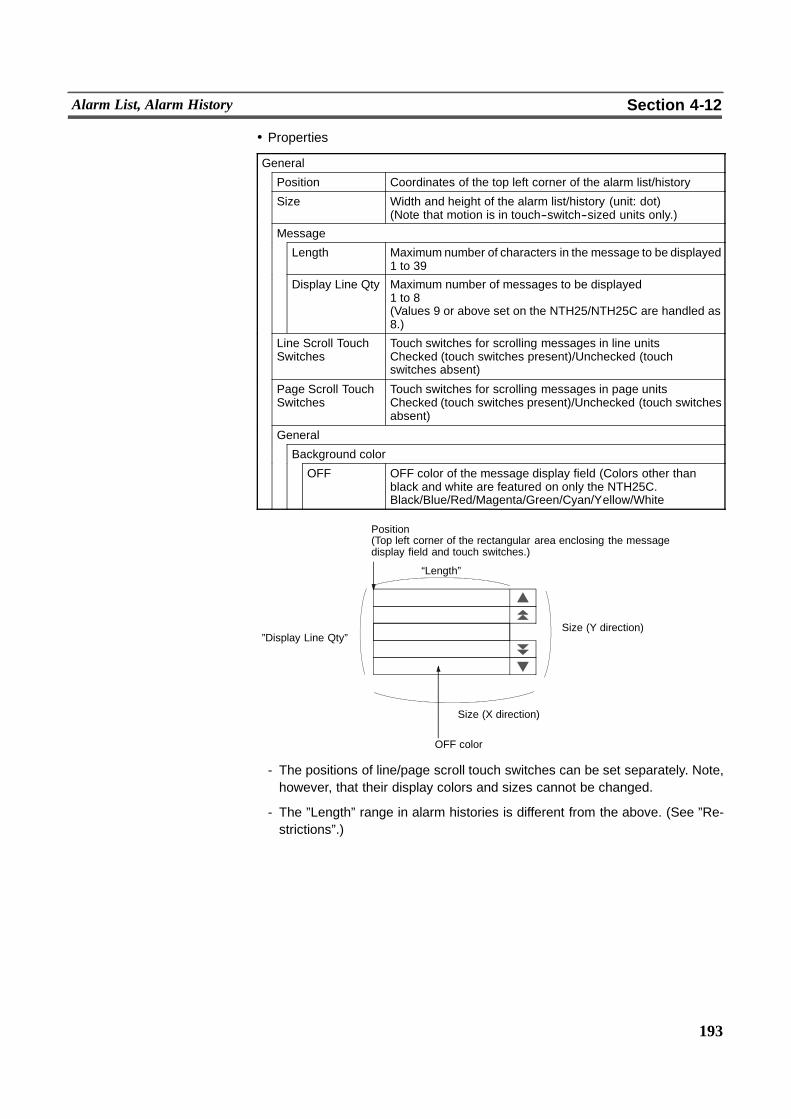
193
Alarm List, Alarm History Section 4-12
! Properties
General
Position Coordinates of the top left corner of the alarm list/history
Size Width and height of the alarm list/history (unit: dot)(Note that motion is in touch--switch--sized units only.)
Message
Length Maximum number of characters in the message to be displayed1 to 39
Display Line Qty Maximum number of messages to be displayed1 to 8(Values 9 or above set on the NTH25/NTH25C are handled as8.)
Line Scroll TouchSwitches
Touch switches for scrolling messages in line unitsChecked (touch switches present)/Unchecked (touchswitches absent)
Page Scroll TouchSwitches
Touch switches for scrolling messages in page unitsChecked (touch switches present)/Unchecked (touch switchesabsent)
General
Background color
OFF OFF color of the message display field (Colors other thanblack and white are featured on only the NTH25C.Black/Blue/Red/Magenta/Green/Cyan/Yellow/White
Position(Top left corner of the rectangular area enclosing the messagedisplay field and touch switches.)
“Length”
OFF color
Size (X direction)
”Display Line Qty”Size (Y direction)
- The positions of line/page scroll touch switches can be set separately. Note,however, that their display colors and sizes cannot be changed.
- The ”Length” range in alarm histories is different from the above. (See ”Re-strictions”.)
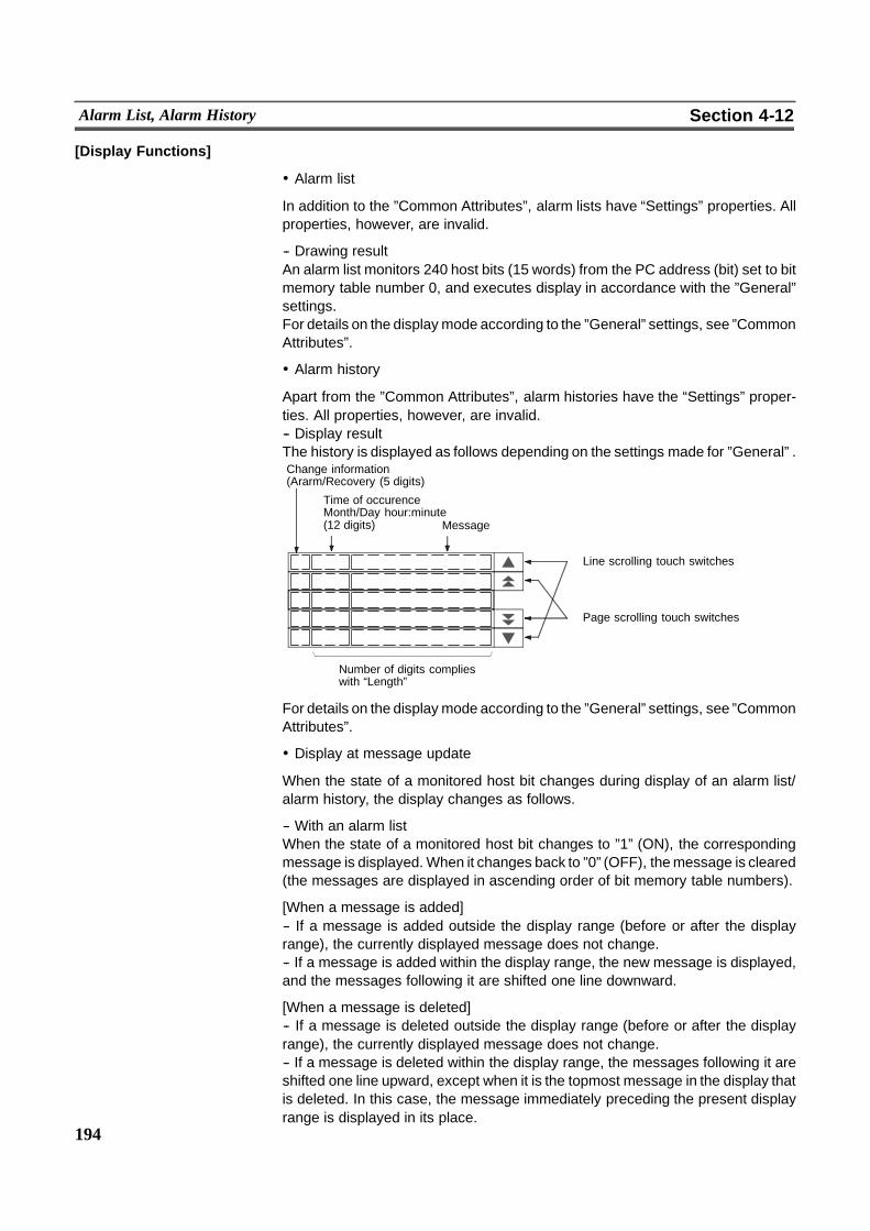
194
Alarm List, Alarm History Section 4-12
[Display Functions]
! Alarm list
In addition to the ”Common Attributes”, alarm lists have “Settings” properties. Allproperties, however, are invalid.
-- Drawing resultAn alarm list monitors 240 host bits (15 words) from the PC address (bit) set to bitmemory table number 0, and executes display in accordance with the ”General”settings.For details on the display mode according to the ”General” settings, see ”CommonAttributes”.
! Alarm history
Apart from the ”Common Attributes”, alarm histories have the “Settings” proper-ties. All properties, however, are invalid.-- Display resultThe history is displayed as follows depending on the settings made for ”General” .Change information(Ararm/Recovery (5 digits)
Line scrolling touch switches
Page scrolling touch switches
Number of digits complieswith “Length”
Message
Time of occurenceMonth/Day hour:minute(12 digits)
For details on the display mode according to the ”General” settings, see ”CommonAttributes”.
! Display at message update
When the state of a monitored host bit changes during display of an alarm list/alarm history, the display changes as follows.
-- With an alarm listWhen the state of a monitored host bit changes to ”1” (ON), the correspondingmessage is displayed. When it changes back to ”0” (OFF), themessage is cleared(the messages are displayed in ascending order of bit memory table numbers).
[When a message is added]-- If a message is added outside the display range (before or after the displayrange), the currently displayed message does not change.-- If a message is added within the display range, the new message is displayed,and the messages following it are shifted one line downward.
[When a message is deleted]-- If a message is deleted outside the display range (before or after the displayrange), the currently displayed message does not change.-- If a message is deleted within the display range, the messages following it areshifted one line upward, except when it is the topmost message in the display thatis deleted. In this case, the message immediately preceding the present displayrange is displayed in its place.

195
Alarm List, Alarm History Section 4-12
! Alarm history
When the status of the monitored host bit changes to ”1” (ON), the correspondingmessage becomes the latest message and is appended to the history record.When the state of the bit changes back to ”0” (OFF), the message remains dis-played.Since newmessages are added at the end of the history, the displayedmessagesdo not change. If the states ofmultiple bits change to ”1” (ON) at the same time, thebit memory table with the smallest bit memory table number is given priority.
! Note on clearing alarm history record data
Alarm history record data that is currently recorded internally by theNTH25/NTH25C is retained by a capacitor when operation is stopped, for exam-ple, during use of the programming console function, or when the power is turnedOFF. Note, however, that the capacitor discharges and the record data will becleared after a few days. Record data is also cleared when screen data is sent toNTH25/NTH25C memory.
[Input Functions]
Alarm lists and alarm histories do not have a direct input function as they displaythe contents of words on the host via bit memory tables. Note, however, that theNTH25/NTH25C does not actually have bit memory tables, so actually the Alarmlists and alarm histories read the contents of words on the host.
[Output Functions]
Alarm lists and alarm histories have no output function.
[Processing Functions]
Alarm lists and alarm histories have no data processing function.
[Relationship with Other Elements]
- Alarm lists and alarm histories monitor the states of host bits and display mes-sages, in accordance with the settings of bit memory tables. For details, see”Bit Memory Tables” (page 103).
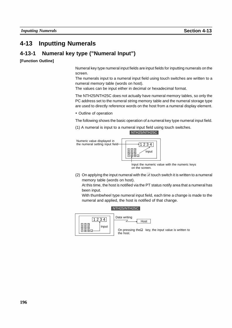
196
Inputting Numerals Section 4-13
4-13 Inputting Numerals
4-13-1 Numeral key type (”Numeral Input”)[Function Outline]
Numeral key type numeral input fields are input fields for inputting numerals on thescreen.The numerals input to a numeral input field using touch switches are written to anumeral memory table (words on host).The values can be input either in decimal or hexadecimal format.
The NTH25/NTH25C does not actually have numeral memory tables, so only thePC address set to the numeral string memory table and the numeral storage typeare used to directly reference words on the host from a numeral display element.
! Outline of operation
The following shows the basic operation of a numeral key type numeral input field.
(1) A numeral is input to a numeral input field using touch switches.
Input1 2 34 5 67 8 9
1 2 3 4
NTH25/NTH25C
Numeric value displayed inthe numeral setting input field
Input the numeric value with the numeric keyson the screen.
(2) On applying the input numeral with the touch switch it is written to a numeralmemory table (words on host).At this time, the host is notified via the PT status notify area that a numeral hasbeen input.With thumbwheel type numeral input field, each time a change is made to thenumeral and applied, the host is notified of that change.
Input1 2 34 5 67 8 9
1 2 3 4
NT31/NT31C
Data writing
On pressing the key, the input value is written tothe host.
NTH25/NTH25C
Host
197
Inputting Numerals Section 4-13
[Restrictions]
- Themaximum number of numeral input elements that can be registered to onescreen varies as follows according to the communications method:[Host link, NT link (1:1)]Max. 80 total of numeral key types and thumbwheel typesThe number of numeral input elements is counted according to their displayorder, and elements exceeding this maximum are discarded. Note, however,that on the Support Tool numeral key type and thumbwheel type numeral inputelements are counted individually. So, both of their display orders cannot bechecked simultaneously. Take care to prevent this limit from being exceeded,and thoroughly check the screen on the NTH25/NTH25C before operation.[Memory link]Max. 80 total of numeral key types and thumbwheel typesThe number of numeral input elements is counted in order from the smallestnumeral memory table number, and elements exceeding this maximum arediscarded. (The same numeral memory table cannot be set to two or more nu-meral input elements in the same screen.)
- There is no restriction on the number of input fields that can be registered toone screen data file; any number can be registered as long as the maximumdata file size is not exceeded.
- The range of numerals that can be input varies on the ”Storage Type” (BCD/binary) of the numeralmemory table, and the ”Display Type” (decimal/hexade-cimal), and ”Display Type” settings made for the numeral input element. Fordetails, see ”Input numeral and stored data” (page 200).
- The number of words on the host that are referenced by numeral input ele-ments is as follows depending on the number of display digits:
When the number of digits in the integer part + number of digits past thedecimal point is =< 4 digits: 1 wordWhen the number of digits in the integer part + number of digits past thedecimal point is > 5 digits: 2 words
- With numeral key type numeral input elements on the standard screen (basescreen), numerals in the process of being entered are not displayed. The nu-merals are displayed once the or ENT key is pressed to apply the entry.Note, however, that the previous numeral remains displayed if the numeralyou entered is in error or is caught in the limit check.With numeral key type numeral input fields (temporary input fields) on windowscreens, numerals in the process of being entered are displayed. Note, how-ever, that the previous numeral remains displayed if the numeral you enteredis in error or is caught in the limit check.
- Themaximum number of digits that can be set on the Support Tool is ten. How-ever, on theNTH25/NTH25C, themaximum is eight for the integer part and sixfor the decimal fraction. The sign digit and decimal point are counted as onedigit each. Set the number of digits taking this restriction into consideration toprevent mismatch with the display on the Support Tool.
- On the Support Tool, signed display can be set. However, minus numbers can-not be entered in numeral input on the NTH25/NTH25C. So this setting is in-valid.
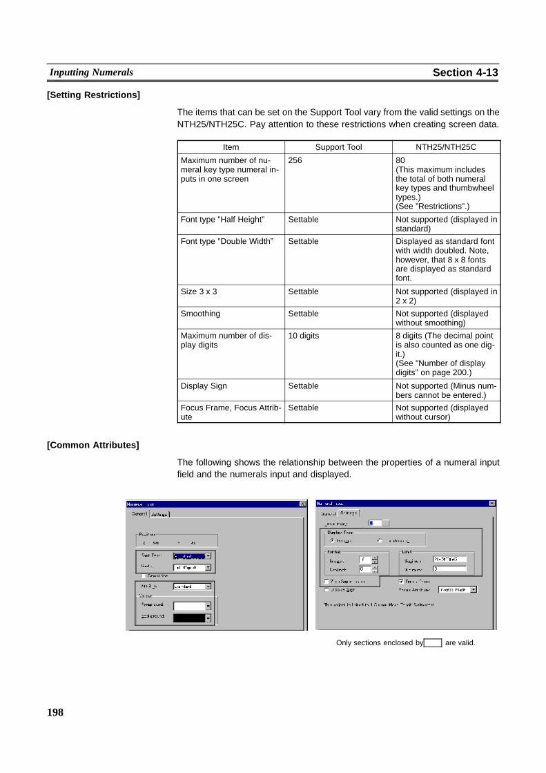
198
Inputting Numerals Section 4-13
[Setting Restrictions]
The items that can be set on the Support Tool vary from the valid settings on theNTH25/NTH25C. Pay attention to these restrictions when creating screen data.
Item Support Tool NTH25/NTH25C
Maximum number of nu-meral key type numeral in-puts in one screen
256 80(This maximum includesthe total of both numeralkey types and thumbwheeltypes.)(See ”Restrictions”.)
Font type ”Half Height” Settable Not supported (displayed instandard)
Font type ”Double Width” Settable Displayed as standard fontwith width doubled. Note,however, that 8 x 8 fontsare displayed as standardfont.
Size 3 x 3 Settable Not supported (displayed in2 x 2)
Smoothing Settable Not supported (displayedwithout smoothing)
Maximum number of dis-play digits
10 digits 8 digits (The decimal pointis also counted as one dig-it.)(See ”Number of displaydigits” on page 200.)
Display Sign Settable Not supported (Minus num-bers cannot be entered.)
Focus Frame, Focus Attrib-ute
Settable Not supported (displayedwithout cursor)
[Common Attributes]
The following shows the relationship between the properties of a numeral inputfield and the numerals input and displayed.
Only sections enclosed by are valid.
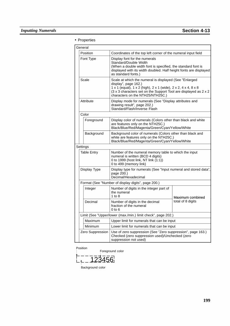
199
Inputting Numerals Section 4-13
! Properties
General
Position Coordinates of the top left corner of the numeral input field
Font Type Display font for the numeralsStandard/Double Width(When a double width font is specified, the standard font isdisplayed with its width doubled. Half height fonts are displayedas standard fonts.)
Scale Scale at which the numeral is displayed (See ”Enlargeddisplay”, page 162.)1 x 1 (equal), 1 x 2 (high), 2 x 1 (wide), 2 x 2, 4 x 4, 8 x 8(3 x 3 characters set on the Support Tool are displayed as 2 x 2characters on the NTH25/NTH25C.)
Attribute Display mode for numerals (See ”Display attributes anddrawing result”, page 202.)Standard/Flash/Inverse Flash
Color
Foreground Display color of numerals (Colors other than black and whiteare features only on the NTH25C.)Black/Blue/Red/Magenta/Green/Cyan/Yellow/White
Background Background color of numerals (Colors other than black andwhite are features only on the NTH25C.)Black/Blue/Red/Magenta/Green/Cyan/Yellow/White
Settings
Table Entry Number of the numeral memory table to which the inputnumeral is written (BCD 4 digits)0 to 1999 (host link, NT link (1:1))0 to 499 (memory link)
Display Type Display type for numerals (See ”Input numeral and stored data”,page 200.)Decimal/Hexadecimal
Format (See ”Number of display digits”, page 200.)
Integer Number of digits in the integer part ofthe numeral1 to 8 Maximum combined
Decimal Number of digits in the decimalfraction of the numeral0 to 6
Maximum combinedtotal of 8 digits
Limit (See ”Upper/lower (max./min.) limit check”, page 202.)
Maximum Upper limit for numerals that can be input
Minimum Lower limit for numerals that can be input
Zero Suppression Use of zero suppression (See ”Zero suppression”, page 163.)Checked (zero suppression used)/Unchecked (zerosuppression not used)
Background color
123456
PositionForeground color
200
Inputting Numerals Section 4-13
! Number of display digits
All numerals are stored as integers to words on the host. To display a numeral thathas a decimal fraction in a numeral input field, set the ”Decimal” setting to ”1” orhigher to specify the number of places past the decimal point. A decimal point isautomatically inserted.If the number of numeral digits is greater than the ”Integer” and ”Decimal” total, theupper digits are discarded, and only the displayable lower integer digits and thedecimal fraction are displayed.Themaximum number of digits in the integer part is eight, and the maximum num-ber of digits past the decimal point is six. Up to a total of eight digits including onedigit for the decimal point can be specified.
Example: Displaying ”123456”-- Setting for ”Integer” = 8 and ”Decimal” = 0:
Resulting display: 00123456-- Setting for ”Integer” = 4 and ”Decimal” = 4:
Resulting display: 12.3456-- Setting for ”Integer” = 2 and ”Decimal” = 4:
Resulting display: 12.3456-- Setting for ”Integer” = 1 and ”Decimal” = 4:
Resulting display: 2.3456
! Input numeral and stored data
The range of numerals that can be input and the conversion method for storingnumerals depend on the following factors:
Numeral Storage Type (BCD/binary)Display Type (decimal/hexadecimal)
<Function of Numeral Storage Type>The numeral storage type determines whether the contents of words on the hostare recognized as BCD (Binary Coded Decimal) or binary (hexadecimal). Numer-als are converted according to thismethod alsowhenwords on the host arewrittento.Note, however, that minus numbers cannot be entered in numeral input on theNTH25/NTH25C.
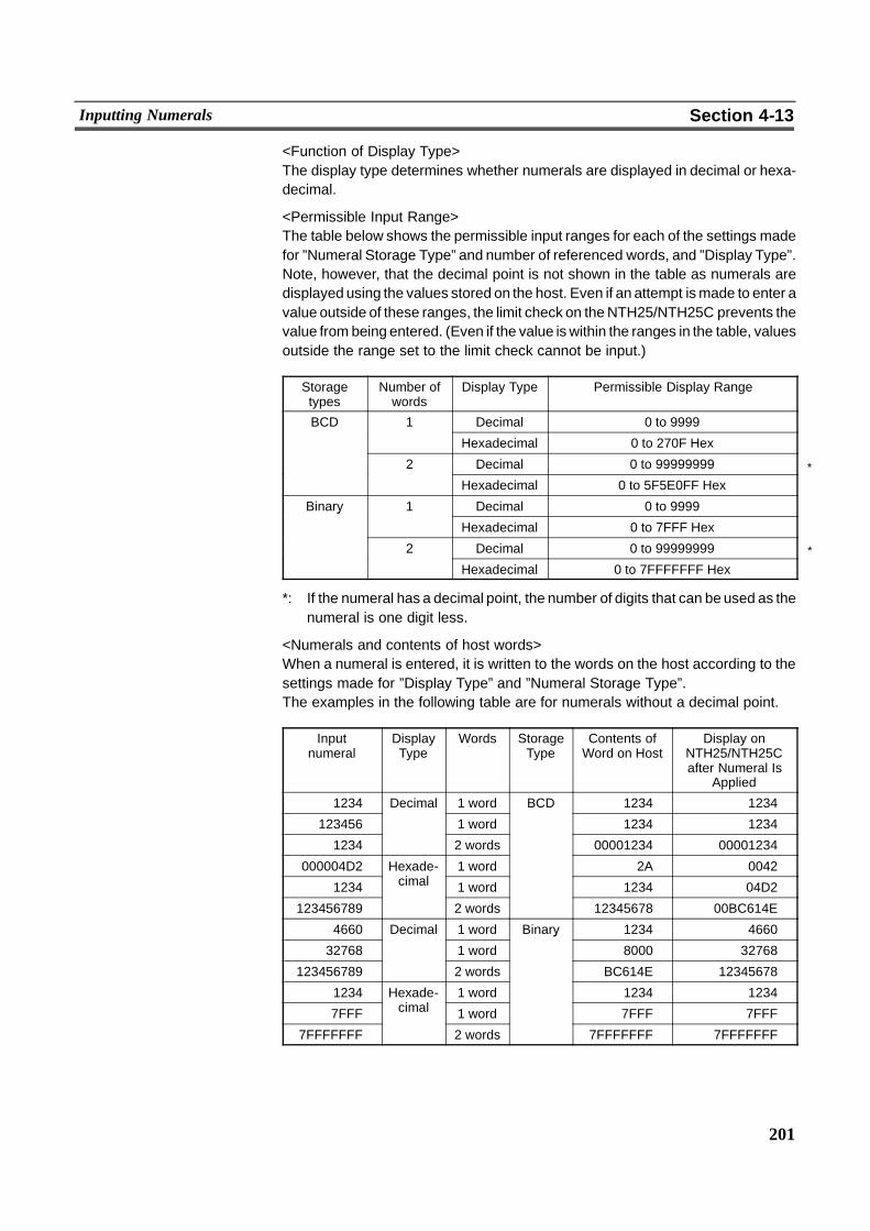
*
*
201
Inputting Numerals Section 4-13
<Function of Display Type>The display type determines whether numerals are displayed in decimal or hexa-decimal.
<Permissible Input Range>The table below shows the permissible input ranges for each of the settings madefor ”Numeral Storage Type” and number of referenced words, and ”Display Type”.Note, however, that the decimal point is not shown in the table as numerals aredisplayed using the values stored on the host. Even if an attempt ismade to enter avalue outside of these ranges, the limit check on theNTH25/NTH25C prevents thevalue from being entered. (Even if the value is within the ranges in the table, valuesoutside the range set to the limit check cannot be input.)
Storagetypes
Number ofwords
Display Type Permissible Display Range
BCD 1 Decimal 0 to 9999
Hexadecimal 0 to 270F Hex
2 Decimal 0 to 99999999
Hexadecimal 0 to 5F5E0FF Hex
Binary 1 Decimal 0 to 9999y
Hexadecimal 0 to 7FFF Hex
2 Decimal 0 to 99999999
Hexadecimal 0 to 7FFFFFFF Hex
*: If the numeral has a decimal point, the number of digits that can be used as thenumeral is one digit less.
<Numerals and contents of host words>When a numeral is entered, it is written to the words on the host according to thesettings made for ”Display Type” and ”Numeral Storage Type”.The examples in the following table are for numerals without a decimal point.
Inputnumeral
DisplayType
Words StorageType
Contents ofWord on Host
Display onNTH25/NTH25Cafter Numeral Is
Applied
1234 Decimal 1 word BCD 1234 1234
123456 1 word 1234 1234
1234 2 words 00001234 00001234
000004D2 Hexade-i l
1 word 2A 0042
1234 cimal 1 word 1234 04D2
123456789 2 words 12345678 00BC614E
4660 Decimal 1 word Binary 1234 4660
32768 1 word
y
8000 32768
123456789 2 words BC614E 12345678
1234 Hexade-i l
1 word 1234 1234
7FFF cimal 1 word 7FFF 7FFF
7FFFFFFF 2 words 7FFFFFFF 7FFFFFFF

202
Inputting Numerals Section 4-13
Reference - When the ”Numeral Storage Type” is set to BCD, entered numerals are con-verted to BCD data before they are written to words on the host. Note, however,that when a value that is not a BCD is entered, the value will not be entered ordisplayed as intended. For example, some digits will be ignored.When the ”Numeral Storage Type” is set to binary, entered numerals are con-verted to hexadecimal data before they are written to words on the host.
- When the ”Numeral Storage type” is set to BCD, set the ”Display Type” to deci-mal. Even if ”Display Type” is set to hexadecimal, entered numerals are treatedas BCD and cannot be input correctly.
- Thoughminus numbers cannot be entered on theNTH25/NTH25C, minus num-bers are sometimes displayed in the numeral input field on the NTH25/NTH25Cwhen a minus number is stored to the contents of words on the host.
! Upper/lower (max./min.) limit check
The NTH25/NTH25C has a function for checking the correctness of an input nu-meral. This prevents a numeral outside the permissible range from being input sothat the input of an illegal value will not adversely affect the system.In the case of a numeral key type numeral input field, the limit check is executedwhen an attempt is made to apply a numeral. If the value is higher than the upperlimit or lower than the lower limit, the input value is cleared. (The status returns tothat before input was attempted.)
Caution Be sure to use the limit check function to ensure safe use of the numeral inputfunction.
! Display attribute and drawing result
Attribute Drawing Result
Standard The numeral display is displayed at the specifiedforeground color and background color.
12345678Flash Repeated alternation of the ”standard” display and no
display.
& No display12345678Inverse Flash Repeated inverted display of each of the foreground and
background colors and no display.
12345678 & No display
! Specifying the input field when there are multiple input fields
When the screen contains multiple input fields, specify the required numeral inputfield by the cursor move touch switch.Note, however, that on the NTH25/NTH25C, only the cursor move touch switchthat you use to register numeral input fields to screen is valid. Cursor move touchswitches made for different purposes using the touch switch functions cannot beused even if they are linked to a numeral input field later.
203
Inputting Numerals Section 4-13
[Display Functions]
Numerals are displayed in the numeral input field in accordancewith the ”General”settings.For details on the display mode according to the ”General” settings, see ”CommonAttributes”.
[Input Functions]
Numerals are input to numeral input fields by using the ”control code input key”touch switches.
[Output Functions]
Numeral inputs do not have a direct input function as they write to words on thehost via numeral memory tables. Note, however, that the NTH25/NTH25C doesnot actually have numeral memory tables, so actually numeral inputs write towords on the host.The host is notified that a numeral has been input by the PT status notify area.
[Processing Functions]
With numeral input fields, input numerals are converted to display numerals in ac-cordance with the ”Settings” property.For details on the method of conversion using the ”Settings” property, see ”Com-mon Attributes”.
[Relationship with Other Elements]
- ”Numeral display” (page 159) use the same conversion method and displaymode as numeral input fields.
- Input and apply touch switches are required to use numeral input fields.
- A cursor move touch switch must bemade for numeral key type numeral inputfields, so numeral input fields cannot overlap each other, and numeral inputfields cannot overlap touch switches.
4-13-2 Thumbwheel Type (Thumbwheel)[Function Outline]
Thumbwheel type numeric input fields are input fields for inputting numerals on thescreen.Touch switches are provided to increment or decrement each digit of a numeral,making it easier to change numerals and to write them to numeral memory tables.The values can be input in either decimal or hexadecimal format.
The NTH25/NTH25C does not actually have numeral memory tables, so only thePCaddress currently set to the numeral string memory table and the numeral stor-age type are used to directly reference words on the host from a numeral displayelement.
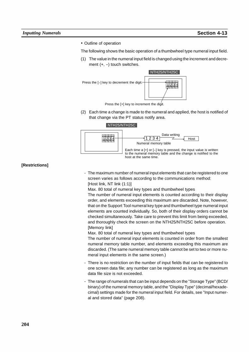
204
Inputting Numerals Section 4-13
! Outline of operation
The following shows the basic operation of a thumbwheel type numeral input field.
(1) The value in the numeral input field is changed using the increment anddecre-ment (+, --) touch switches.
+ + + +Press the [(] key to decrement the digit.
Press the [+] key to increment the digit.
( ( ( (1 2 3 4
NTH25/NTH25C
(2) Each time a change is made to the numeral and applied, the host is notified ofthat change via the PT status notify area.
+ + + +
( ( ( (1 2 3 4
Data writing
Numeral memory tableHost1 2 3 4
Each time a [+] or [(] key is pressed, the input value is writtento the numeral memory table and the change is notified to thehost at the same time.
NTH25/NTH25C
[Restrictions]
- Themaximum number of numeral input elements that can be registered to onescreen varies as follows according to the communications method:[Host link, NT link (1:1)]Max. 80 total of numeral key types and thumbwheel typesThe number of numeral input elements is counted according to their displayorder, and elements exceeding this maximum are discarded. Note, however,that on the Support Tool numeral key type and thumbwheel type numeral inputelements are counted individually. So, both of their display orders cannot bechecked simultaneously. Take care to prevent this limit from being exceeded,and thoroughly check the screen on the NTH25/NTH25C before operation.[Memory link]Max. 80 total of numeral key types and thumbwheel typesThe number of numeral input elements is counted in order from the smallestnumeral memory table number, and elements exceeding this maximum arediscarded. (The same numeral memory table cannot be set to two or more nu-meral input elements in the same screen.)
- There is no restriction on the number of input fields that can be registered toone screen data file; any number can be registered as long as the maximumdata file size is not exceeded.
- The range of numerals that can be input depends on the ”Storage Type” (BCD/binary) of the numeralmemory table, and the ”Display Type” (decimal/hexade-cimal) settings made for the numeral input field. For details, see ”Input numer-al and stored data” (page 208).
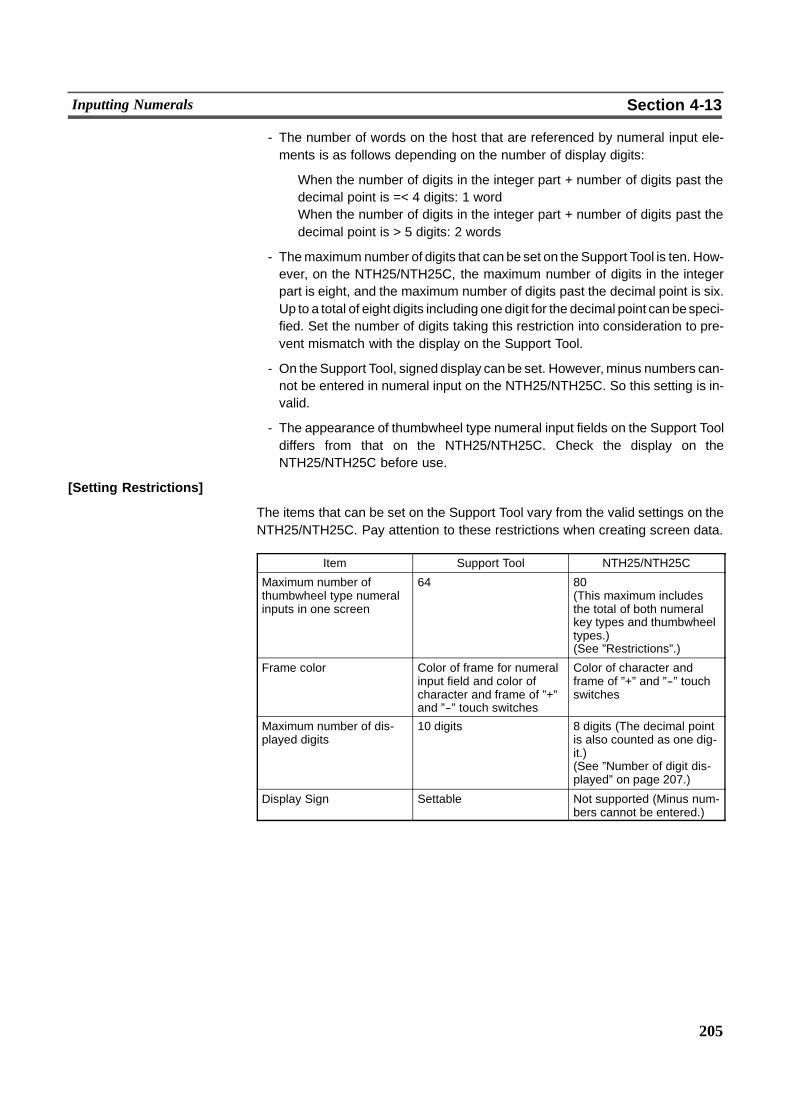
205
Inputting Numerals Section 4-13
- The number of words on the host that are referenced by numeral input ele-ments is as follows depending on the number of display digits:
When the number of digits in the integer part + number of digits past thedecimal point is =< 4 digits: 1 wordWhen the number of digits in the integer part + number of digits past thedecimal point is > 5 digits: 2 words
- Themaximum number of digits that can be set on the Support Tool is ten. How-ever, on the NTH25/NTH25C, the maximum number of digits in the integerpart is eight, and the maximum number of digits past the decimal point is six.Up to a total of eight digits including one digit for the decimal point can bespeci-fied. Set the number of digits taking this restriction into consideration to pre-vent mismatch with the display on the Support Tool.
- On the Support Tool, signed display can be set. However, minus numbers can-not be entered in numeral input on the NTH25/NTH25C. So this setting is in-valid.
- The appearance of thumbwheel type numeral input fields on the Support Tooldiffers from that on the NTH25/NTH25C. Check the display on theNTH25/NTH25C before use.
[Setting Restrictions]
The items that can be set on the Support Tool vary from the valid settings on theNTH25/NTH25C. Pay attention to these restrictions when creating screen data.
Item Support Tool NTH25/NTH25C
Maximum number ofthumbwheel type numeralinputs in one screen
64 80(This maximum includesthe total of both numeralkey types and thumbwheeltypes.)(See ”Restrictions”.)
Frame color Color of frame for numeralinput field and color ofcharacter and frame of ”+”and ”--” touch switches
Color of character andframe of ”+” and ”--” touchswitches
Maximum number of dis-played digits
10 digits 8 digits (The decimal pointis also counted as one dig-it.)(See ”Number of digit dis-played” on page 207.)
Display Sign Settable Not supported (Minus num-bers cannot be entered.)
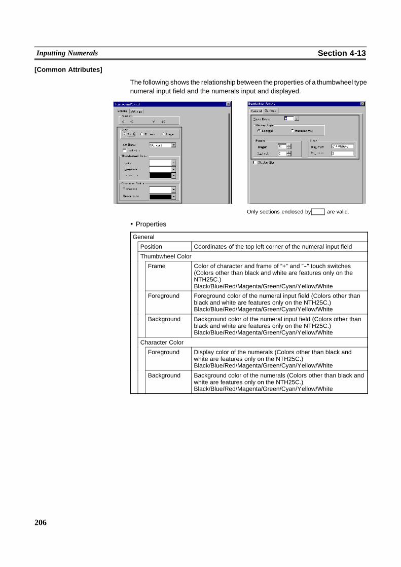
206
Inputting Numerals Section 4-13
[Common Attributes]
The following shows the relationship between the properties of a thumbwheel typenumeral input field and the numerals input and displayed.
Only sections enclosed by are valid.
! Properties
General
Position Coordinates of the top left corner of the numeral input field
Thumbwheel Color
Frame Color of character and frame of ”+” and ”--” touch switches(Colors other than black and white are features only on theNTH25C.)Black/Blue/Red/Magenta/Green/Cyan/Yellow/White
Foreground Foreground color of the numeral input field (Colors other thanblack and white are features only on the NTH25C.)Black/Blue/Red/Magenta/Green/Cyan/Yellow/White
Background Background color of the numeral input field (Colors other thanblack and white are features only on the NTH25C.)Black/Blue/Red/Magenta/Green/Cyan/Yellow/White
Character Color
Foreground Display color of the numerals (Colors other than black andwhite are features only on the NTH25C.)Black/Blue/Red/Magenta/Green/Cyan/Yellow/White
Background Background color of the numerals (Colors other than black andwhite are features only on the NTH25C.)Black/Blue/Red/Magenta/Green/Cyan/Yellow/White
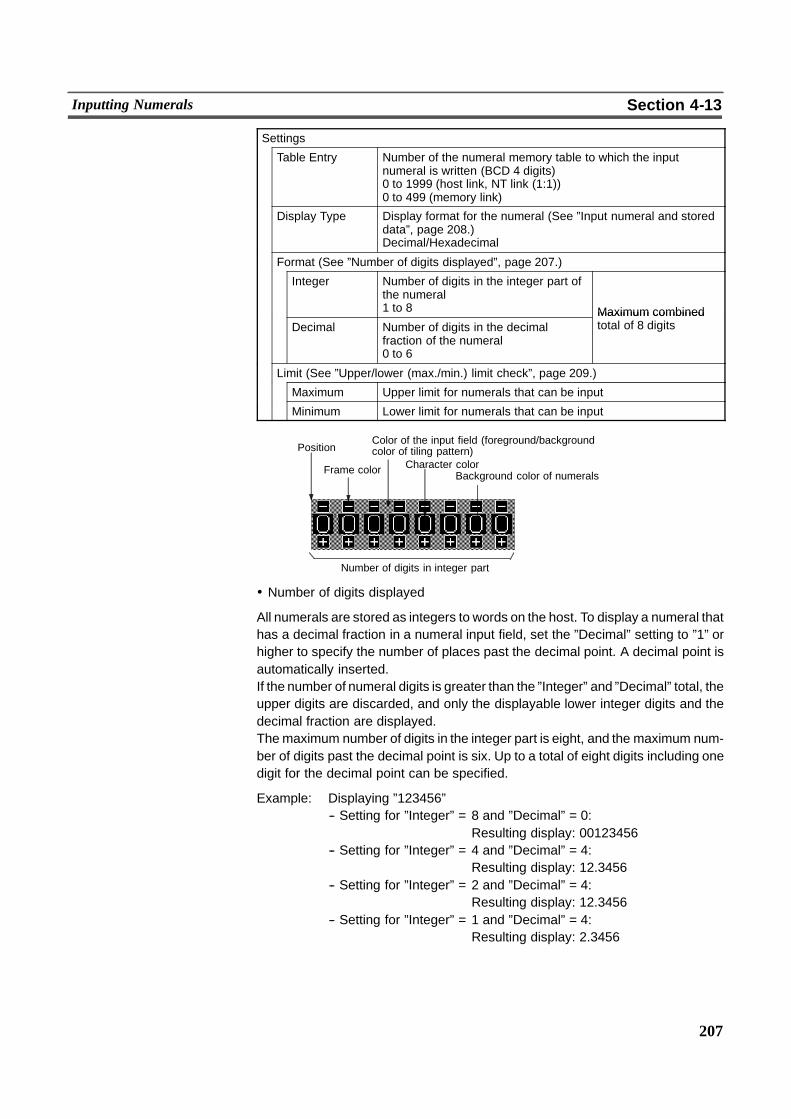
207
Inputting Numerals Section 4-13
Settings
Table Entry Number of the numeral memory table to which the inputnumeral is written (BCD 4 digits)0 to 1999 (host link, NT link (1:1))0 to 499 (memory link)
Display Type Display format for the numeral (See ”Input numeral and storeddata”, page 208.)Decimal/Hexadecimal
Format (See ”Number of digits displayed”, page 207.)
Integer Number of digits in the integer part ofthe numeral1 to 8 Maximum combined
Decimal Number of digits in the decimalfraction of the numeral0 to 6
Maximum combinedtotal of 8 digits
Limit (See ”Upper/lower (max./min.) limit check”, page 209.)
Maximum Upper limit for numerals that can be input
Minimum Lower limit for numerals that can be input
Position
Number of digits in integer part
Frame color Character colorBackground color of numerals
Color of the input field (foreground/backgroundcolor of tiling pattern)
! Number of digits displayed
All numerals are stored as integers to words on the host. To display a numeral thathas a decimal fraction in a numeral input field, set the ”Decimal” setting to ”1” orhigher to specify the number of places past the decimal point. A decimal point isautomatically inserted.If the number of numeral digits is greater than the ”Integer” and ”Decimal” total, theupper digits are discarded, and only the displayable lower integer digits and thedecimal fraction are displayed.Themaximum number of digits in the integer part is eight, and the maximum num-ber of digits past the decimal point is six. Up to a total of eight digits including onedigit for the decimal point can be specified.
Example: Displaying ”123456”-- Setting for ”Integer” = 8 and ”Decimal” = 0:
Resulting display: 00123456-- Setting for ”Integer” = 4 and ”Decimal” = 4:
Resulting display: 12.3456-- Setting for ”Integer” = 2 and ”Decimal” = 4:
Resulting display: 12.3456-- Setting for ”Integer” = 1 and ”Decimal” = 4:
Resulting display: 2.3456
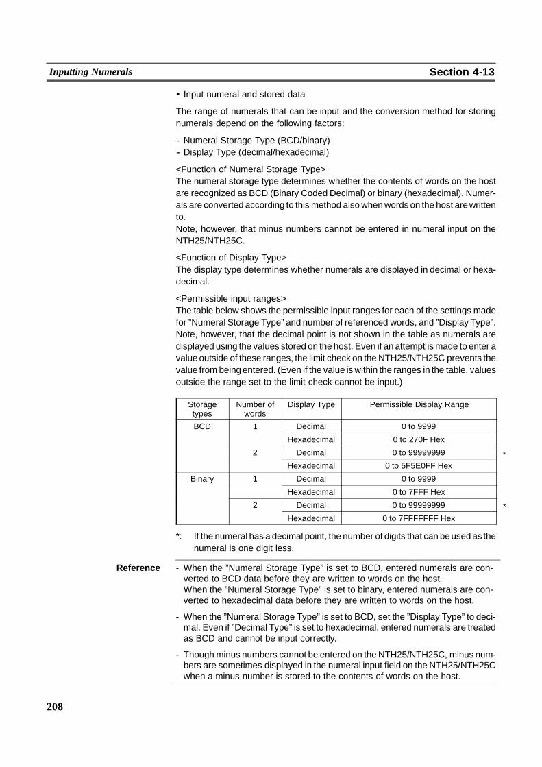
*
*
208
Inputting Numerals Section 4-13
! Input numeral and stored data
The range of numerals that can be input and the conversion method for storingnumerals depend on the following factors:
-- Numeral Storage Type (BCD/binary)-- Display Type (decimal/hexadecimal)
<Function of Numeral Storage Type>The numeral storage type determines whether the contents of words on the hostare recognized as BCD (Binary Coded Decimal) or binary (hexadecimal). Numer-als are converted according to thismethod alsowhenwords on the host arewrittento.Note, however, that minus numbers cannot be entered in numeral input on theNTH25/NTH25C.
<Function of Display Type>The display type determines whether numerals are displayed in decimal or hexa-decimal.
<Permissible input ranges>The table below shows the permissible input ranges for each of the settings madefor ”Numeral Storage Type” and number of referenced words, and ”Display Type”.Note, however, that the decimal point is not shown in the table as numerals aredisplayed using the values stored on the host. Even if an attempt ismade to enter avalue outside of these ranges, the limit check on theNTH25/NTH25C prevents thevalue from being entered. (Even if the value is within the ranges in the table, valuesoutside the range set to the limit check cannot be input.)
Storagetypes
Number ofwords
Display Type Permissible Display Range
BCD 1 Decimal 0 to 9999
Hexadecimal 0 to 270F Hex
2 Decimal 0 to 99999999
Hexadecimal 0 to 5F5E0FF Hex
Binary 1 Decimal 0 to 9999y
Hexadecimal 0 to 7FFF Hex
2 Decimal 0 to 99999999
Hexadecimal 0 to 7FFFFFFF Hex
*: If the numeral has a decimal point, the number of digits that can beused as thenumeral is one digit less.
Reference - When the ”Numeral Storage Type” is set to BCD, entered numerals are con-verted to BCD data before they are written to words on the host.When the ”Numeral Storage Type” is set to binary, entered numerals are con-verted to hexadecimal data before they are written to words on the host.
- When the ”Numeral Storage Type” is set to BCD, set the ”Display Type” to deci-mal. Even if ”Decimal Type” is set to hexadecimal, entered numerals are treatedas BCD and cannot be input correctly.
- Thoughminus numbers cannot be entered on theNTH25/NTH25C, minus num-bers are sometimes displayed in the numeral input field on the NTH25/NTH25Cwhen a minus number is stored to the contents of words on the host.
209
Inputting Numerals Section 4-13
! Upper/lower (max./min.) limit check
The NTH25/NTH25C has a function for checking the correctness of an input nu-meral. This prevents a numeral outside the permissible range from being input sothat the input of an illegal value will not adversely affect the system.The upper/lower (max./min.) limit check is executed at the following timing accord-ing to the type of numeral input field.For a thumbwheel type numeral input field, the check is executed each that timethe increment/decrement key of each digit position is pressed.Note, however, that carry over and underflow are no longer possible at the highestdigit position if n andm are in the relationship n...n <m...m [upper limit: 1n...n, low-er limit: 0m...m (”n” and ”m” are arbitrary values at each digit)].
Example: If the upper limit value and the lower limit value are 1200 and 201,respectively, the numeral can be changedonly in the following range:from 201 to 999 if the default is a 3--digit value and from 1000 to 1200if the default is a 4--digit value.The reason for this is that the upper/lower (max./min.) limit checkfunction does not allow the numeral at the highest digit position tochange from 0 to 1 or from 1 to 0.To avoid this, either set the upper and lower limit values so that therelationship becomes ”n...n >=m...m”, or provide a touch switch sep-arately to write a numeral for carry over or underflow.
Caution Upper/lower limits are checked when the entered numeral values are applied.
[Display Functions]
Numerals are displayed in the numeral input field in accordancewith the ”General”settings.For details on the display mode according to the ”General” settings, see ”CommonAttributes”.
[Input Functions]
Numerals are input to a thumbwheel type numeral input field by using the ”+” and”--” touch switches provided for each digit.
[Output Functions]
Numeral inputs do not have a direct input function as they write to words on thehost via numeral memory tables. Note, however, that the NTH25/NTH25C doesnot actually have numeral memory tables, so actually numeral inputs write towords on the host.The host is notified that a numeral has been input by the PT status notify area.
[Processing Functions]
With numeral input fields, input numerals are converted to display numerals in ac-cordance with the ”Settings” property.For details on the method of conversion using the ”Settings” property, see ”Com-mon Attributes”.
210
Inputting Numerals Section 4-13
[Relationship with Other Elements]
- ”Numeral display” (page 159) use the same conversion method and displaymode as numeral input fields.
- A cursor move touch switch must bemade for numeral key type numeral inputfields, so numeral input fields cannot overlap each other, and numeral inputfields cannot overlap touch switches.
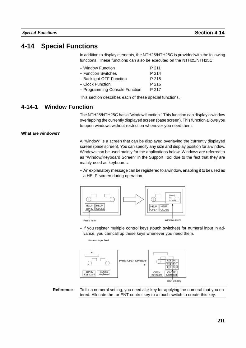
211
Special Functions Section 4-14
4-14 Special FunctionsIn addition to display elements, the NTH25/NTH25C is provided with the followingfunctions. These functions can also be executed on the NTH25/NTH25C.
-- Window Function P 211-- Function Switches P 214-- Backlight OFF Function P 215-- Clock Function P 216-- Programming Console Function P 217
This section describes each of these special functions.
4-14-1 Window FunctionThe NTH25/NTH25C has a ”window function.” This function can display a windowoverlapping the currently displayed screen (base screen). This function allows youto open windows without restriction whenever you need them.
What are windows?
A ”window” is a screen that can be displayed overlaying the currently displayedscreen (base screen). You can specify any size and display position for a window.Windows can be used mainly for the applications below. Windows are referred toas ”Window/Keyboard Screen” in the Support Tool due to the fact that they aremainly used as keyboards.
-- An explanatorymessage can be registered to awindow, enabling it to be used asa HELP screen during operation.
Press here Window opens
Control
the
conveyor.
HELPOPEN
HELPCLOSE
HELPOPEN
HELPCLOSE
-- If you register multiple control keys (touch switches) for numeral input in ad-vance, you can call up these keys whenever you need them.
Numeral input field
Input window
OPENKeyboard
1 2 3 04 5 6 .7 8 9 �Press ”OPEN Keyboard”
CLOSEKeyboard
OPENKeyboard
CLOSEKeyboard
Reference To fix a numeral setting, you need a key for applying the numeral that you en-tered. Allocate the or ENT control key to a touch switch to create this key.

212
Special Functions Section 4-14
-- If you register multiple screen switching keys (touch switches) in advances, youcan use these keys as menus for switching the screen.
Press here When “Graph” is pressed
When “Next” is pressed
MENU MENU
MENU MENU
Next
Graph
Window Screens and Display Elements
The window function allows you to create a window in any of the user screens,numbered 1 to 1000. (A screen to which a window is registered is called a ”windowscreen”.)You can register up to 20 window screens to one screen data file.When a screen is registered as a window screen, you must specify the windowarea to set the size of the window. The window is always displayed at the ”windowarea” size.The window position becomes the position of the ”window area” on the windowscreen. (You cannot change this position.)
You can register the following elements onNTH25/NTH25Cwindowscreens. Oth-er elements are invalid in window screens.
-- Fixed display elements (characters, graphics, marks)
-- Touch switches (Input notify touch switch is not allowed.)
-- Numeral input field (Only one can be used. This becomes the ”temporary inputfield.”)
Reference - Elements that project off thewindowareawill not be displayedwhen thewindowopens.
- Display processing slows down slightly while a window is open.
- On the NTH25/NTH25C, the window screen can no longer be used when evenpart of a window overlaps a touch switch on the base screen.
Opening/closing a window
On the NTH25/NTH25C, windows are opened and closed as follows:
-- By pressing a touch switch having a ”pop--up keyboard function”
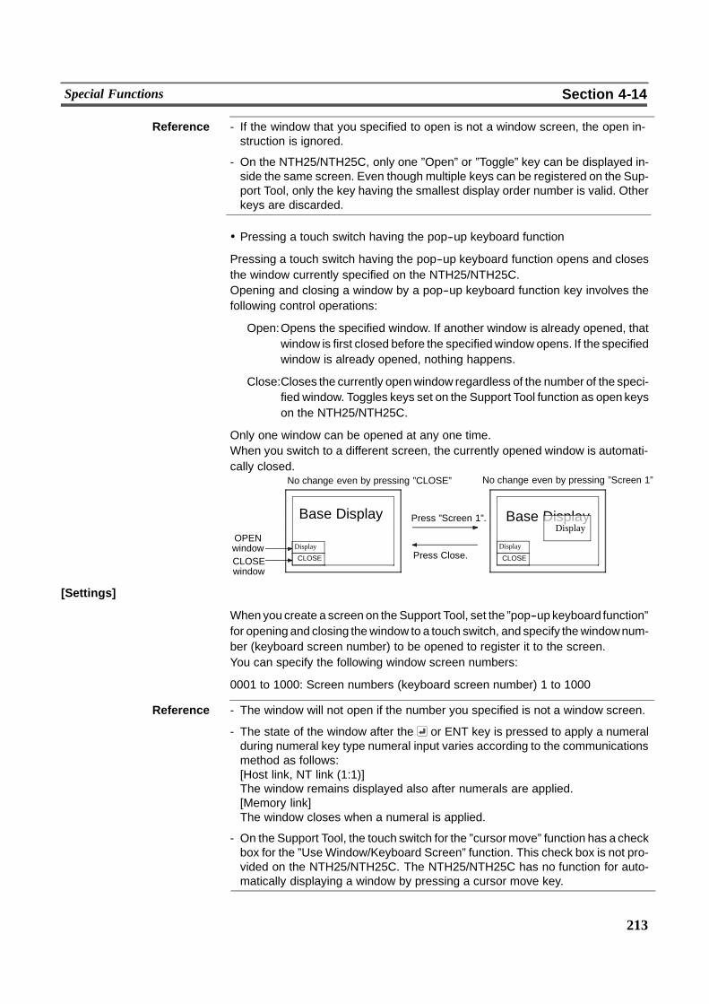
213
Special Functions Section 4-14
Reference - If the window that you specified to open is not a window screen, the open in-struction is ignored.
- On the NTH25/NTH25C, only one ”Open” or ”Toggle” key can be displayed in-side the same screen. Even though multiple keys can be registered on the Sup-port Tool, only the key having the smallest display order number is valid. Otherkeys are discarded.
! Pressing a touch switch having the pop--up keyboard function
Pressing a touch switch having the pop--up keyboard function opens and closesthe window currently specified on the NTH25/NTH25C.Opening and closing a window by a pop--up keyboard function key involves thefollowing control operations:
Open:Opens the specified window. If another window is already opened, thatwindow is first closed before the specifiedwindow opens. If the specifiedwindow is already opened, nothing happens.
Close:Closes the currently openwindow regardless of the number of the speci-fied window. Toggles keys set on the Support Tool function as open keyson the NTH25/NTH25C.
Only one window can be opened at any one time.When you switch to a different screen, the currently opened window is automati-cally closed.
No change even by pressing ”CLOSE”
Base Display
No change even by pressing ”Screen 1”
CLOSE
Display
Base DisplayDisplay
Press ”Screen 1”.
Press Close.CLOSEwindow
CLOSE
DisplayOPENwindow
[Settings]
When you create a screen on the Support Tool, set the ”pop--up keyboard function”for opening and closing thewindow to a touch switch, and specify thewindownum-ber (keyboard screen number) to be opened to register it to the screen.You can specify the following window screen numbers:
0001 to 1000: Screen numbers (keyboard screen number) 1 to 1000
Reference - The window will not open if the number you specified is not a window screen.
- The state of the window after the or ENT key is pressed to apply a numeralduring numeral key type numeral input varies according to the communicationsmethod as follows:[Host link, NT link (1:1)]The window remains displayed also after numerals are applied.[Memory link]The window closes when a numeral is applied.
- On the Support Tool, the touch switch for the ”cursormove” function has a checkbox for the ”UseWindow/Keyboard Screen” function. This check box is not pro-vided on the NTH25/NTH25C. The NTH25/NTH25C has no function for auto-matically displaying a window by pressing a cursor move key.
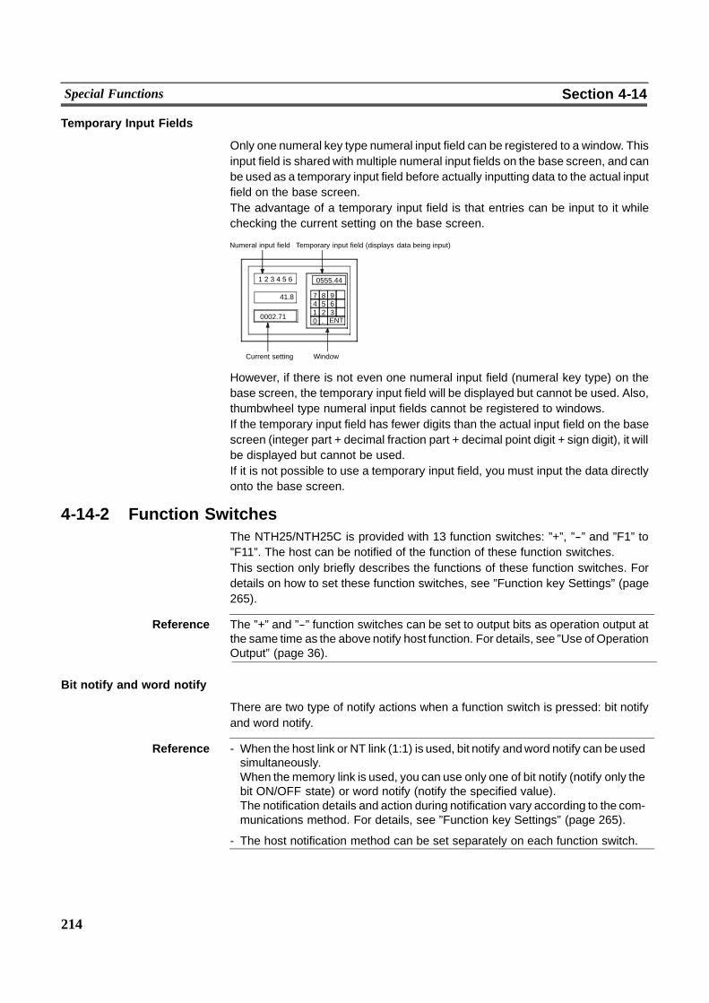
214
Special Functions Section 4-14
Temporary Input Fields
Only one numeral key type numeral input field can be registered to a window. Thisinput field is shared with multiple numeral input fields on the base screen, and canbe used as a temporary input field before actually inputting data to the actual inputfield on the base screen.The advantage of a temporary input field is that entries can be input to it whilechecking the current setting on the base screen.
Numeral input field Temporary input field (displays data being input)
WindowCurrent setting
1 2 3 4 5 6
����41.8
0002.71
7 8 9 �4 5 6 �1 2 3 �0 . ENT
0555.44
41.8
However, if there is not even one numeral input field (numeral key type) on thebase screen, the temporary input field will be displayed but cannot be used. Also,thumbwheel type numeral input fields cannot be registered to windows.If the temporary input field has fewer digits than the actual input field on the basescreen (integer part + decimal fraction part + decimal point digit + sign digit), it willbe displayed but cannot be used.If it is not possible to use a temporary input field, you must input the data directlyonto the base screen.
4-14-2 Function SwitchesThe NTH25/NTH25C is provided with 13 function switches: ”+”, ”--” and ”F1” to”F11”. The host can be notified of the function of these function switches.This section only briefly describes the functions of these function switches. Fordetails on how to set these function switches, see ”Function key Settings” (page265).
Reference The ”+” and ”--” function switches can be set to output bits as operation output atthe same time as the above notify host function. For details, see ”Use of OperationOutput” (page 36).
Bit notify and word notify
There are two type of notify actions when a function switch is pressed: bit notifyand word notify.
Reference - When the host link or NT link (1:1) is used, bit notify andword notify can be usedsimultaneously.When thememory link is used, you can use only one of bit notify (notify only thebit ON/OFF state) or word notify (notify the specified value).The notification details and action during notification vary according to the com-munications method. For details, see ”Function key Settings” (page 265).
- The host notification method can be set separately on each function switch.
215
Special Functions Section 4-14
! Bit notify
The host is notified of changes in the switch state.Two notify actions are available: notification only when the switch is pressed (mo-mentary), and notification when the switch is pressed and then released (alter-nate).
! Word notify
When the switch is pressed, the host is notified of a number (binary, 4--digit hexa-decimal) currently set by the NTH Screen Data Converter.
4-14-3 Backlight OFF FunctionThe NTH25/NTH25C has a backlight OFF function for turning the screenOFF if itis not operated for a fixed period of time. The purpose of this function is to extendthe service life of the backlight.This backlight OFF function operates only while the NTH25/NTH25C is running,and can only started up in the CHECK menu or in the RUN mode.
Caution When the backlight is out or the display state is ”no--display,” do not inadvertentlytouch a touch switch or function switch.Check the safety of the system before you touch a touch switch or function switch.
Reference - The backlight can also be turned OFF by setting the state of the PT status con-trol bit, bit 0 (backlight mode). Note, however, that ”Configuration” -- ”Auto CFLoff” must be set to (disable backlight auto OFF function) on the NTH ScreenData Converter when the PT status control bit is used. So, the PT control areabit and the backlight auto OFF function cannot be used simultaneously.
- The backlight OFF function does not function while screen switching is periodi-cally being performed from the host.
Turning the backlight ON again
The above operations can turn the backlight back ON again when the backlightOFF function is activated and the backlight is OFF:
-- Pressing a function switch-- Touching a touch panel-- Switching the screen from the host
If you touch a touch switch while the backlight is OFF, only the operation of turningthe backlight ON again is executed and touch switch functions (e.g. notification tohost, screen switching) are not executed. (Whena function switch is pressed, noti-fication of the function switch also is executed.)
Reference - When the backlight is turned OFF by manipulating the PT status control bit, itcan be turned ON again only by setting the PT status control bit ”backlightmode” (bit 0) to 1 (ON). (The backlight cannot be turned ON again by the aboveoperation.)
- The backlight will not turn ON again when display contents (e.g. currently dis-played numerals and character strings) are only updated.
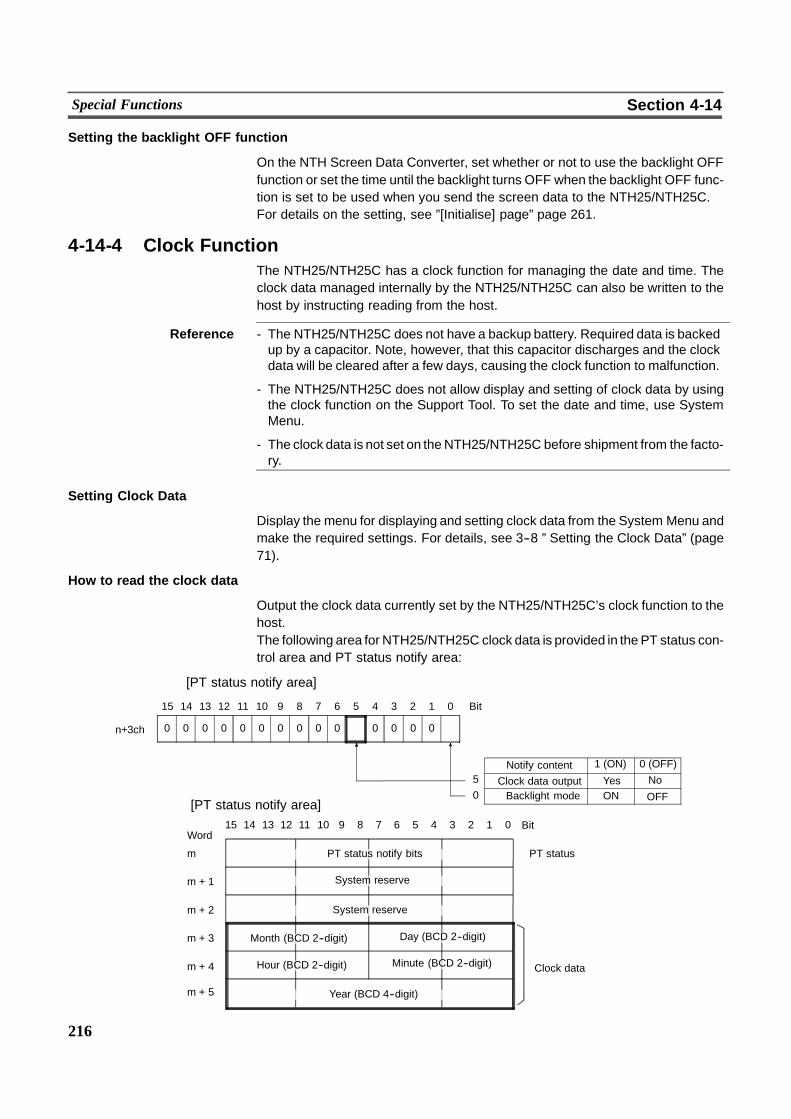
216
Special Functions Section 4-14
Setting the backlight OFF function
On the NTH Screen Data Converter, set whether or not to use the backlight OFFfunction or set the time until the backlight turns OFF when the backlight OFF func-tion is set to be used when you send the screen data to the NTH25/NTH25C.For details on the setting, see ”[Initialise] page” page 261.
4-14-4 Clock FunctionThe NTH25/NTH25C has a clock function for managing the date and time. Theclock data managed internally by the NTH25/NTH25C can also be written to thehost by instructing reading from the host.
Reference - The NTH25/NTH25C does not have a backup battery. Required data is backedup by a capacitor. Note, however, that this capacitor discharges and the clockdata will be cleared after a few days, causing the clock function to malfunction.
- The NTH25/NTH25C does not allow display and setting of clock data by usingthe clock function on the Support Tool. To set the date and time, use SystemMenu.
- The clock data is not set on theNTH25/NTH25C before shipment from the facto-ry.
Setting Clock Data
Display the menu for displaying and setting clock data from the System Menu andmake the required settings. For details, see 3--8 ” Setting the Clock Data” (page71).
How to read the clock data
Output the clock data currently set by the NTH25/NTH25C’s clock function to thehost.The following area for NTH25/NTH25C clock data is provided in the PT status con-trol area and PT status notify area:
15 14 13 12 11 10 9 8 7 6 5 4 3 2 1 0Word
Bit
m PT status notify bits PT status
m + 1 System reserve
m + 2
m + 3 Month (BCD 2--digit)
Clock datam + 4 Hour (BCD 2--digit)
System reserve
Year (BCD 4--digit)
Day (BCD 2--digit)
Minute (BCD 2--digit)
m + 5
ON OFF
00
1415 13 12 11 10 9 8 7 Bit
Notify content 1 (ON) 0 (OFF)
0
6 5 4 3 2 1 0
0
Clock data output Yes No5
Backlight mode0
00 00000000n+3ch
[PT status notify area]
[PT status notify area]
217
Special Functions Section 4-14
[Settings]
ThePT status control area andPT status notify areamust be allocated towords onthe host. So, settings for controlling operation on the NTH25/NTH25C are not re-quired.
[Operation]
To output the NTH25/NTH25C’s internal clock to the PT status notify area, manip-ulate the PT status control area as follows.
(1) Set bit 5 of the 4th word (n+3 word) in the PT status control area as follows:n+3 wordBit 5: Clock data outputOutput: 1 (ON)No output: 0 (OFF)Clock data is written at 1--minute intervals to the area for notifying the clockdata in the PT status notify area for the duration that the state of this bit is 1(ON). Note, however, that the clock data output interval may fluctuate whennumerals are frequently input on the NTH25/NTH25C.
4-14-5 Programming Console Function (Expansion Function)As anextended function, theNTH25/NTH25C features the ”programming consolefunction”. This function allows the NTH25/NTH25C to be used in place of a pro-gramming console (model CPM1A) for a C--series CPM1 (CPM1A), or a CQM1,C200HX/HG/HE--EZ or SRM1--C02--V1.Almost all of the programming console functions are possible, with the exceptionof recording (storing) ladder programs on cassette tape and playing (reading)them back.For details on the system configuration for using the programming console func-tion, how to connect to a PC, and how to use the programming console function,see 3--10 ”Programming Console Function” (page 74).
The programming console function can be used even when the PC is in the RUNmode. Note, however the NTH25/NTH25C will stop operating at the same timethat the programming console function is applied. (RUN LED turns OFF.)Pressing the ”Quit” touch switch on the programming console function screenquits the programming console function. The RUN mode is then returned to, andthe screen currently specified at ”Screen Switch Setting” in the PT status controlarea is displayed.
219
SECTION 5Using Memory Link (NTH Protocol)
This section gives an overview of memory link (NTH protocol) operations, and mainly describes communications betweenthe NTH25/NTH25C and host when using memory link (NTH protocol).
5-1 Operation of Memory Link 220. . . . . . . . . . . . . . . . . . . . . . . . . . . . . . . . . . . . . . . . . . . . . . . . . . . . .5-1-1 PT Memory 220. . . . . . . . . . . . . . . . . . . . . . . . . . . . . . . . . . . . . . . . . . . . . . . . . . . . . . . . . . .5-1-2 Configuration of PT Memory 221. . . . . . . . . . . . . . . . . . . . . . . . . . . . . . . . . . . . . . . . . . . . .5-1-3 Key Points When Creating Screen Data 222. . . . . . . . . . . . . . . . . . . . . . . . . . . . . . . . . . . . .
5-2 Outline of Communications 224. . . . . . . . . . . . . . . . . . . . . . . . . . . . . . . . . . . . . . . . . . . . . . .5-2-1 Communications Protocol 224. . . . . . . . . . . . . . . . . . . . . . . . . . . . . . . . . . . . . . . . . . . . . . . .5-2-2 Memory Link Commands/Responses 225. . . . . . . . . . . . . . . . . . . . . . . . . . . . . . . . . . . . . . .5-2-3 Notes on Using Commands 228. . . . . . . . . . . . . . . . . . . . . . . . . . . . . . . . . . . . . . . . . . . . . . .
5-3 Data Structure According to Display Element and Function 230. . . . . . . . . . . . . . . . . . . . .
220
Operation of Memory Link Section 5-1
5-1 Operation of Memory LinkThis section describes the function of the memory link (NTH protocol). For an out-line of the memory link functions, see 1--4 ”Communications by Using MemoryLink”.
5-1-1 PT MemoryWith the NTH25/NTH25C memory link, data transactions between the host andthe NTH25/NTH25C are handled via ”PT memory.” PT memory is automaticallyallocated to each element.PT memory is a virtual PC area within the NTH25/NTH25C. The NTH25/NTH25Creads andwrites to the internal PTmemory, and the host controls andmonitors theNTH25/NTH25C by reading/writing PT memory.With PT memory, there is no classification of the area as there is with real PCareas; it comprises a memory link area of addresses 0000 to 9999 and A000 toA050.With the NTH25/NTH25C memory link, PT memory differs from regular PCmemory in that one address corresponds to a single elements. So, when twowords are used for a single element such as for a numeral display, the data of mul-tiple words corresponds to a single address. (The data of multiple words can beread or written on a single address by memory link commands.)The following table summarizes the differences in theallocatedwords (addresses)between when regular direct accessing is performed and when theNTH25/NTH25C memory link is used.
Item Direct Access Memory Link (NTH protocol)
Address/element corre-spondence
Allocatable to any address(area and position)
Addresses used for eachelement is already deter-mined.
Address/data correspon-dence
-- In case of word address-es: 1 word for 1 ad-dress. In case of bit ad-dresses: 1 bit for 1 ad-dress
-- In case of elements thatuse multiple words, mul-tiple addresses are oc-cupied.
The data volume per 1 ad-dress varies according toelement type.
Reference With the NTH25/NTH25C memory link, addresses are automatically allocated toeach element. So, the PC addresses and number of allocated channels set on theSupport Tool are invalid. (Predetermined bits must be set for only lamp bits.)
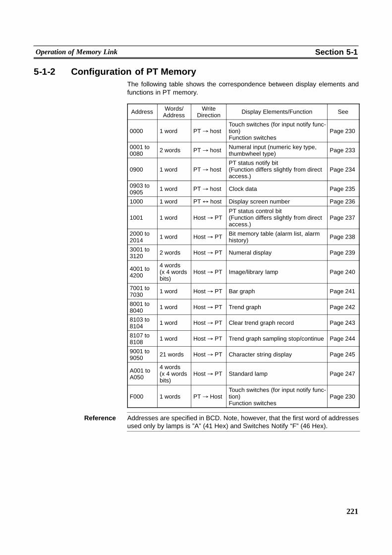
221
Operation of Memory Link Section 5-1
5-1-2 Configuration of PT MemoryThe following table shows the correspondence between display elements andfunctions in PT memory.
Address Words/Address
WriteDirection Display Elements/Function See
0000 1 word PT% hostTouch switches (for input notify func-tion)Function switches
Page 230
0001 to0080 2 words PT% host Numeral input (numeric key type,
thumbwheel type) Page 233
0900 1 word PT% hostPT status notify bit(Function differs slightly from directaccess.)
Page 234
0903 to0905 1 word PT% host Clock data Page 235
1000 1 word PT$ host Display screen number Page 236
1001 1 word Host% PTPT status control bit(Function differs slightly from directaccess.)
Page 237
2000 to2014 1 word Host% PT Bit memory table (alarm list, alarm
history) Page 238
3001 to3120 2 words Host% PT Numeral display Page 239
4001 to4200
4 words(x 4 wordsbits)
Host% PT Image/library lamp Page 240
7001 to7030 1 word Host% PT Bar graph Page 241
8001 to8040 1 word Host% PT Trend graph Page 242
8103 to8104 1 word Host% PT Clear trend graph record Page 243
8107 to8108 1 word Host% PT Trend graph sampling stop/continue Page 244
9001 to9050 21 words Host% PT Character string display Page 245
A001 toA050
4 words(x 4 wordsbits)
Host% PT Standard lamp Page 247
F000 1 words PT% HostTouch switches (for input notify func-tion)Function switches
Page 230
Reference Addresses are specified in BCD. Note, however, that the first word of addressesused only by lamps is ”A” (41 Hex) and Switches Notify “F” (46 Hex).
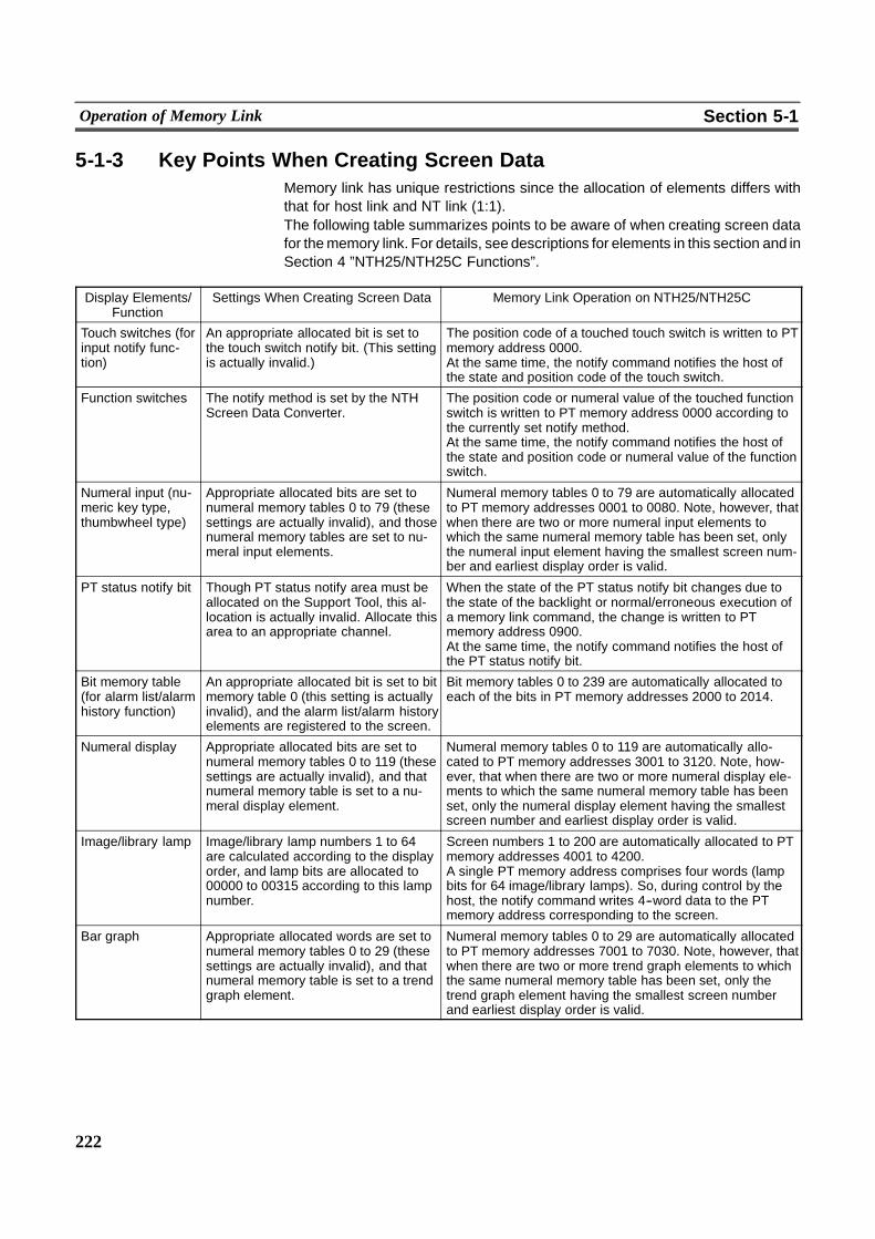
222
Operation of Memory Link Section 5-1
5-1-3 Key Points When Creating Screen DataMemory link has unique restrictions since the allocation of elements differs withthat for host link and NT link (1:1).The following table summarizes points to be aware of when creating screen datafor thememory link. For details, see descriptions for elements in this section and inSection 4 ”NTH25/NTH25C Functions”.
Display Elements/Function
Settings When Creating Screen Data Memory Link Operation on NTH25/NTH25C
Touch switches (forinput notify func-tion)
An appropriate allocated bit is set tothe touch switch notify bit. (This settingis actually invalid.)
The position code of a touched touch switch is written to PTmemory address 0000.At the same time, the notify command notifies the host ofthe state and position code of the touch switch.
Function switches The notify method is set by the NTHScreen Data Converter.
The position code or numeral value of the touched functionswitch is written to PT memory address 0000 according tothe currently set notify method.At the same time, the notify command notifies the host ofthe state and position code or numeral value of the functionswitch.
Numeral input (nu-meric key type,thumbwheel type)
Appropriate allocated bits are set tonumeral memory tables 0 to 79 (thesesettings are actually invalid), and thosenumeral memory tables are set to nu-meral input elements.
Numeral memory tables 0 to 79 are automatically allocatedto PT memory addresses 0001 to 0080. Note, however, thatwhen there are two or more numeral input elements towhich the same numeral memory table has been set, onlythe numeral input element having the smallest screen num-ber and earliest display order is valid.
PT status notify bit Though PT status notify area must beallocated on the Support Tool, this al-location is actually invalid. Allocate thisarea to an appropriate channel.
When the state of the PT status notify bit changes due tothe state of the backlight or normal/erroneous execution ofa memory link command, the change is written to PTmemory address 0900.At the same time, the notify command notifies the host ofthe PT status notify bit.
Bit memory table(for alarm list/alarmhistory function)
An appropriate allocated bit is set to bitmemory table 0 (this setting is actuallyinvalid), and the alarm list/alarm historyelements are registered to the screen.
Bit memory tables 0 to 239 are automatically allocated toeach of the bits in PT memory addresses 2000 to 2014.
Numeral display Appropriate allocated bits are set tonumeral memory tables 0 to 119 (thesesettings are actually invalid), and thatnumeral memory table is set to a nu-meral display element.
Numeral memory tables 0 to 119 are automatically allo-cated to PT memory addresses 3001 to 3120. Note, how-ever, that when there are two or more numeral display ele-ments to which the same numeral memory table has beenset, only the numeral display element having the smallestscreen number and earliest display order is valid.
Image/library lamp Image/library lamp numbers 1 to 64are calculated according to the displayorder, and lamp bits are allocated to00000 to 00315 according to this lampnumber.
Screen numbers 1 to 200 are automatically allocated to PTmemory addresses 4001 to 4200.A single PT memory address comprises four words (lampbits for 64 image/library lamps). So, during control by thehost, the notify command writes 4--word data to the PTmemory address corresponding to the screen.
Bar graph Appropriate allocated words are set tonumeral memory tables 0 to 29 (thesesettings are actually invalid), and thatnumeral memory table is set to a trendgraph element.
Numeral memory tables 0 to 29 are automatically allocatedto PT memory addresses 7001 to 7030. Note, however, thatwhen there are two or more trend graph elements to whichthe same numeral memory table has been set, only thetrend graph element having the smallest screen numberand earliest display order is valid.
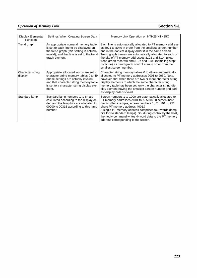
223
Operation of Memory Link Section 5-1
Display Elements/Function
Settings When Creating Screen Data Memory Link Operation on NTH25/NTH25C
Trend graph An appropriate numeral memory tableis set to each line to be displayed onthe trend graph (this setting is actuallyinvalid), and that line is set to the trendgraph element.
Each line is automatically allocated to PT memory address-es 8001 to 8040 in order from the smallest screen numberand in the earliest display order if in the same screen.Trend graph frames are automatically allocated to each ofthe bits of PT memory addresses 8103 and 8104 (cleartrend graph records) and 8107 and 8108 (sampling stop/continue) as trend graph control area in order from thesmallest screen number.
Character stringdisplay
Appropriate allocated words are set tocharacter string memory tables 0 to 49(these settings are actually invalid),and that character string memory tableis set to a character string display ele-ment.
Character string memory tables 0 to 49 are automaticallyallocated to PT memory addresses 9001 to 9050. Note,however, that when there are two or more character stringdisplay elements to which the same character stringmemory table has been set, only the character string dis-play element having the smallest screen number and earli-est display order is valid.
Standard lamp Standard lamp numbers 1 to 64 arecalculated according to the display or-der, and the lamp bits are allocated to00000 to 00315 according to this lampnumber.
Screen numbers 1 to 1000 are automatically allocated toPT memory addresses A001 to A050 in 50 screen incre-ments. (For example, screen numbers 1, 51, 101 ... 951share PT memory address 4001.)A single PT memory address comprises four words (lampbits for 64 standard lamps). So, during control by the host,the notify command writes 4--word data to the PT memoryaddress corresponding to the screen.
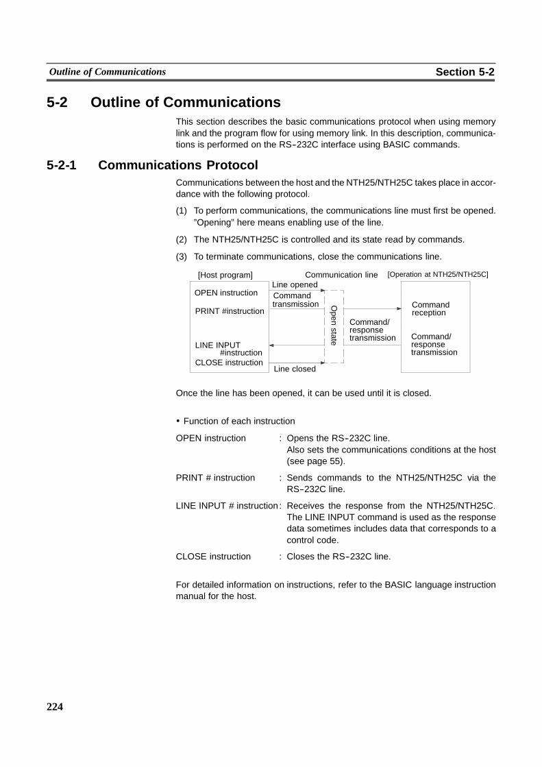
224
Outline of Communications Section 5-2
5-2 Outline of CommunicationsThis section describes the basic communications protocol when using memorylink and the program flow for using memory link. In this description, communica-tions is performed on the RS--232C interface using BASIC commands.
5-2-1 Communications ProtocolCommunications between the host and the NTH25/NTH25C takes place in accor-dance with the following protocol.
(1) To perform communications, the communications line must first be opened.”Opening” here means enabling use of the line.
(2) The NTH25/NTH25C is controlled and its state read by commands.
(3) To terminate communications, close the communications line.
[Host program]
OPEN instruction
PRINT #instruction
LINE INPUT
CLOSE instruction
Line openedCommandtransmission
Line closed
#instruction
Command/responsetransmission Command/
responsetransmission
Commandreception
Communication line
Open
state
���
���������
���
[Operation at NTH25/NTH25C]
Once the line has been opened, it can be used until it is closed.
! Function of each instruction
OPEN instruction : Opens the RS--232C line.Also sets the communications conditions at the host(see page 55).
PRINT # instruction : Sends commands to the NTH25/NTH25C via theRS--232C line.
LINE INPUT # instruction : Receives the response from the NTH25/NTH25C.The LINE INPUT command is used as the responsedata sometimes includes data that corresponds to acontrol code.
CLOSE instruction : Closes the RS--232C line.
For detailed information on instructions, refer to the BASIC language instructionmanual for the host.

225
Outline of Communications Section 5-2
5-2-2 Memory Link Commands/ResponsesWith memory link, data transactions between the host and NTH25/NTH25C arehandled using the following commands and responses.Commands and responses are used according to the following three operations.
! Writing to PT from Host
Data is written to PTmemory from the host according to commands, and the result(normal or erroneous end) is returned as the response.This operation can be performed only on PT memory whose write direction is”Host to PT”.
Reading to Host from PT
The host issues commands for reading the contents of PT memory, and the readdata is returned as the response.This operation can be performed only on PT memory whose write direction is ”PTto host”.
Notifying to Host from PT
The host is notified of changes inPTmemory states as the command. (A responsefrom the host is not required.)The following two changes in PT memory states are notified:
Touch switches/function switches (address 0000)PT status notify bit (address 0900)
Reference When commands are issued continuously, be sure to acknowledge the responsefrom the NTH25/NTH25C for the previous command before issuing the next com-mand.
Writing to PT from Host
[Operation at host]
Command transmission
[Operation at NTH25/NTH25C]
Command receptionData write command
Command processing
Response transmissionResponse receptionRsponse(ACK or NAK)
! Data write command
The write command is sent in the following format. This command can be usedonly for PT memory that can be written to by the host.
05 30
[ENO] ID
5730
[ESC]
1B
W
�� ���� ��
Address
�� ����
D11 D12 D13 D14
��
[CR]
0D�� ����
Dn1 Dn2 Dn3 Dn4
��
Write data
ID : ”00” (30 Hex, 30 Hex) fixed
W : ”W” (57 Hex) fixedThis indicates the write mode.
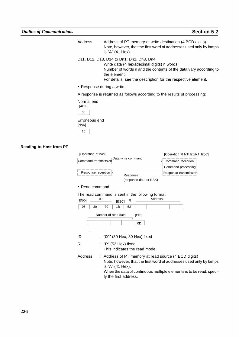
226
Outline of Communications Section 5-2
Address : Address of PT memory at write destination (4 BCD digits)Note, however, that the first word of addresses used only by lampsis ”A” (41 Hex).
D11, D12, D13, D14 to Dn1, Dn2, Dn3, Dn4:Write data (4 hexadecimal digits) n wordsNumber of words n and the contents of the data vary according tothe element.For details, see the description for the respective element.
! Response during a write
A response is returned as follows according to the results of processing:
Normal end
06
[ACK]
Erroneous end
15
[NAK]
Reading to Host from PT
[Operation at host]
Command transmission
[Operation at NTH25/NTH25C]
Command receptionData write command
Command processing
Response transmissionResponse receptionResponse(response data or NAK)
! Read command
The read command is sent in the following format:
05 30
[ENO] ID
5230
[ESC]
1B
R
�� ���� ��
Address
[CR]Number of read data
�� ���� �� 0D
ID : ”00” (30 Hex, 30 Hex) fixed
R : ”R” (52 Hex) fixedThis indicates the read mode.
Address : Address of PT memory at read source (4 BCD digits)Note, however, that the first word of addresses used only by lampsis ”A” (41 Hex).When the data of continuousmultiple elements is to be read, speci-fy the first address.
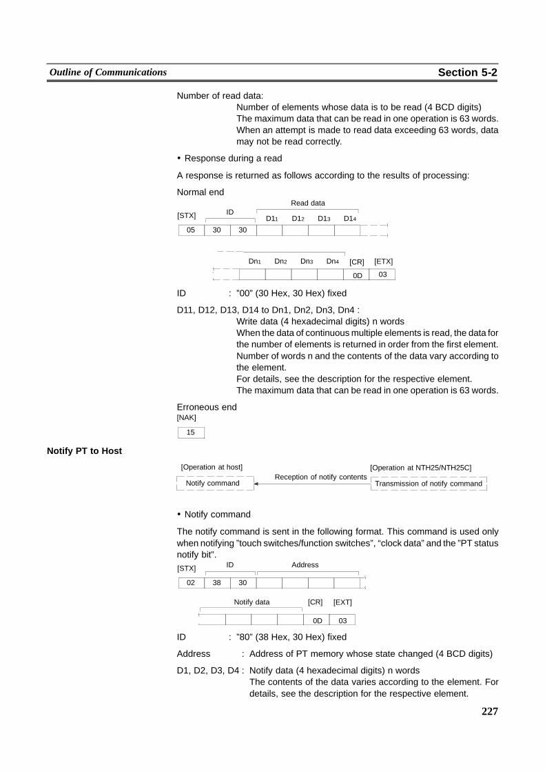
227
Outline of Communications Section 5-2
Number of read data:Number of elements whose data is to be read (4 BCD digits)The maximum data that can be read in one operation is 63 words.When an attempt is made to read data exceeding 63 words, datamay not be read correctly.
! Response during a read
A response is returned as follows according to the results of processing:
Normal end
05 30
[STX] ID
30 �� ���� ��
Read data
[CR]
�� ���� �� 0D
D11 D12 D13 D14
Dn1 Dn2 Dn3 Dn4 [ETX]
03
ID : ”00” (30 Hex, 30 Hex) fixed
D11, D12, D13, D14 to Dn1, Dn2, Dn3, Dn4 :Write data (4 hexadecimal digits) n wordsWhen the data of continuousmultiple elements is read, the data forthe number of elements is returned in order from the first element.Number of words n and the contents of the data vary according tothe element.For details, see the description for the respective element.The maximum data that can be read in one operation is 63 words.
Erroneous end
15
[NAK]
Notify PT to Host
[Operation at host] [Operation at NTH25/NTH25C]
Transmission of notify commandNotify commandReception of notify contents
! Notify command
The notify command is sent in the following format. This command is used onlywhen notifying ”touch switches/function switches”, “clock data” and the ”PT statusnotify bit”.
02 38
[STX] ID
30 �� ���� ��
Address
[CR]Notify data
�� ���� �� 0D
[EXT]
03
ID : ”80” (38 Hex, 30 Hex) fixed
Address : Address of PT memory whose state changed (4 BCD digits)
D1, D2, D3, D4 : Notify data (4 hexadecimal digits) n wordsThe contents of the data varies according to the element. Fordetails, see the description for the respective element.
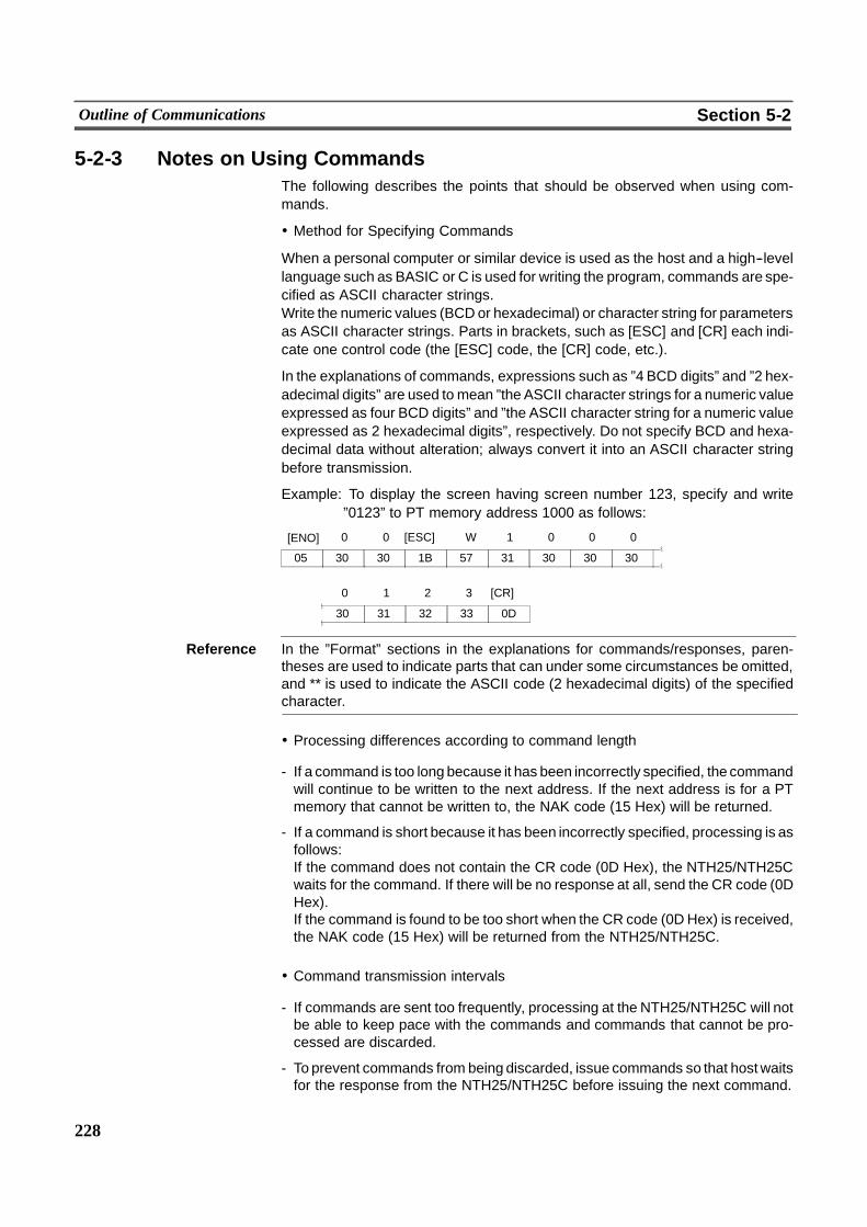
228
Outline of Communications Section 5-2
5-2-3 Notes on Using CommandsThe following describes the points that should be observed when using com-mands.
! Method for Specifying Commands
When a personal computer or similar device is used as the host and a high--levellanguage such as BASIC or C is used for writing the program, commands are spe-cified as ASCII character strings.Write the numeric values (BCDor hexadecimal) or character string for parametersas ASCII character strings. Parts in brackets, such as [ESC] and [CR] each indi-cate one control code (the [ESC] code, the [CR] code, etc.).
In the explanations of commands, expressions such as ”4 BCD digits” and ”2 hex-adecimal digits” are used to mean ”the ASCII character strings for a numeric valueexpressed as four BCD digits” and ”the ASCII character string for a numeric valueexpressed as 2 hexadecimal digits”, respectively. Do not specify BCD and hexa-decimal data without alteration; always convert it into an ASCII character stringbefore transmission.
Example: To display the screen having screen number 123, specify and write”0123” to PT memory address 1000 as follows:
05 30
[ENO]
5730
[ESC]
1B
W
31 3030 30
32 3331
0 1 2 3
30
[CR]
0D
1 0 0 000
Reference In the ”Format” sections in the explanations for commands/responses, paren-theses are used to indicate parts that can under some circumstances be omitted,and ** is used to indicate the ASCII code (2 hexadecimal digits) of the specifiedcharacter.
! Processing differences according to command length
- If a command is too long because it has been incorrectly specified, the commandwill continue to be written to the next address. If the next address is for a PTmemory that cannot be written to, the NAK code (15 Hex) will be returned.
- If a command is short because it has been incorrectly specified, processing is asfollows:If the command does not contain the CR code (0D Hex), the NTH25/NTH25Cwaits for the command. If there will be no response at all, send the CR code (0DHex).If the command is found to be too short when the CR code (0DHex) is received,the NAK code (15 Hex) will be returned from the NTH25/NTH25C.
! Command transmission intervals
- If commands are sent too frequently, processing at the NTH25/NTH25C will notbe able to keep pace with the commands and commands that cannot be pro-cessed are discarded.
- To prevent commands from being discarded, issue commands so that hostwaitsfor the response from the NTH25/NTH25C before issuing the next command.
229
Outline of Communications Section 5-2
! Order of priority of input communications commands
- When a reason for input notification arises during processing of a commandfrom the host, the input command is issued only after processing of the currentlyexecuting command has ended.
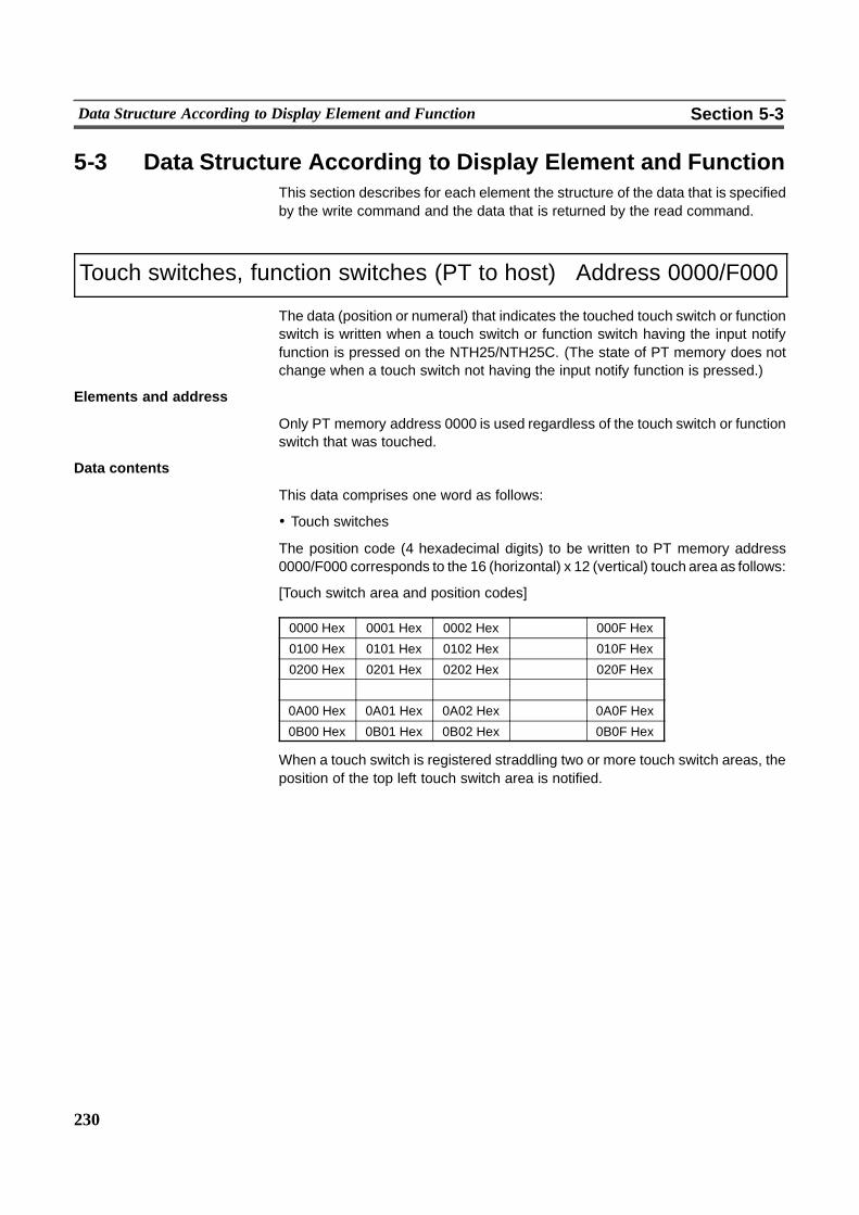
� � � �
230
Data Structure According to Display Element and Function Section 5-3
5-3 Data Structure According to Display Element and FunctionThis section describes for each element the structure of the data that is specifiedby the write command and the data that is returned by the read command.
Touch switches, function switches (PT to host) Address 0000/F000
The data (position or numeral) that indicates the touched touch switch or functionswitch is written when a touch switch or function switch having the input notifyfunction is pressed on the NTH25/NTH25C. (The state of PT memory does notchange when a touch switch not having the input notify function is pressed.)
Elements and address
Only PT memory address 0000 is used regardless of the touch switch or functionswitch that was touched.
Data contents
This data comprises one word as follows:
! Touch switches
The position code (4 hexadecimal digits) to be written to PT memory address0000/F000 corresponds to the 16 (horizontal) x 12 (vertical) touch area as follows:
[Touch switch area and position codes]
0000 Hex 0001 Hex 0002 Hex � 000F Hex
0100 Hex 0101 Hex 0102 Hex � 010F Hex
0200 Hex 0201 Hex 0202 Hex � 020F Hex
0A00 Hex 0A01 Hex 0A02 Hex � 0A0F Hex
0B00 Hex 0B01 Hex 0B02 Hex � 0B0F Hex
When a touch switch is registered straddling two or more touch switch areas, theposition of the top left touch switch area is notified.
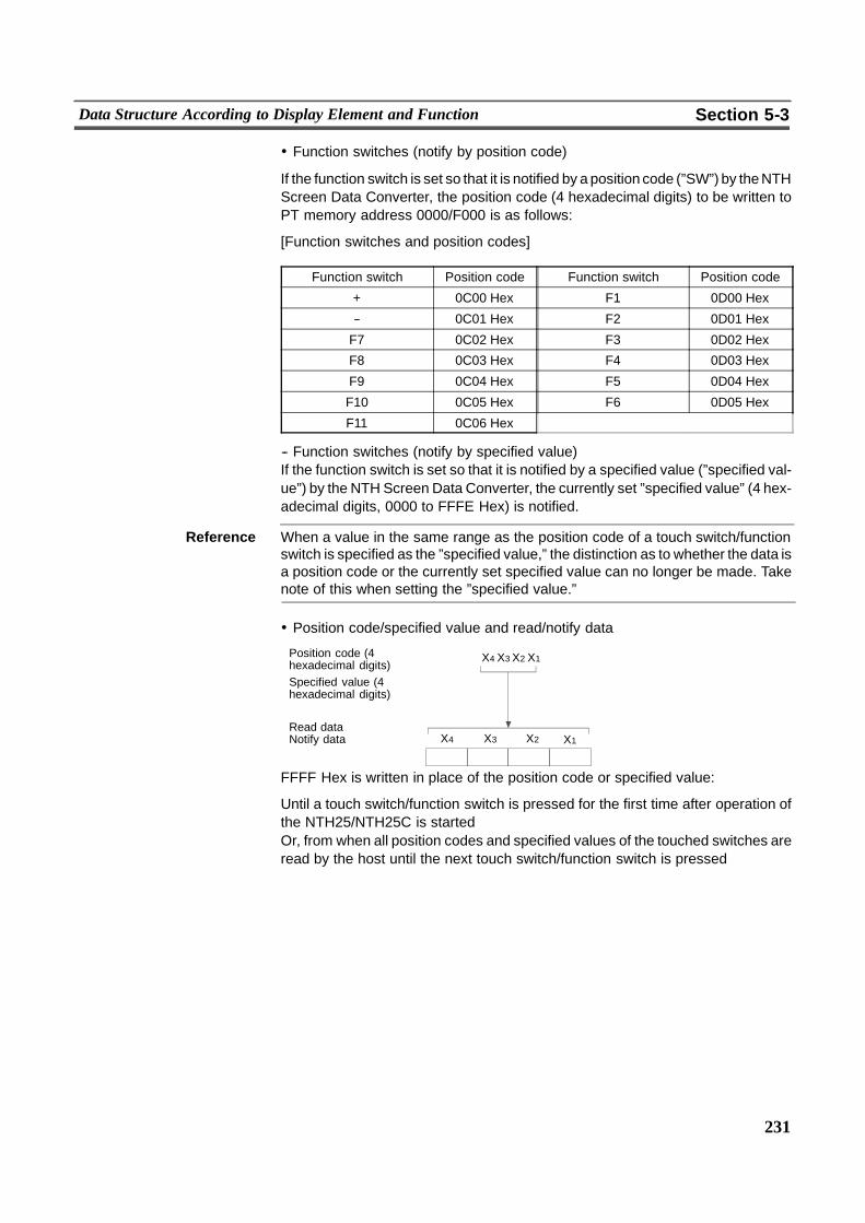
231
Data Structure According to Display Element and Function Section 5-3
! Function switches (notify by position code)
If the function switch is set so that it is notified by a position code (”SW”) by theNTHScreen Data Converter, the position code (4 hexadecimal digits) to be written toPT memory address 0000/F000 is as follows:
[Function switches and position codes]
Function switch Position code Function switch Position code
+ 0C00 Hex F1 0D00 Hex
-- 0C01 Hex F2 0D01 Hex
F7 0C02 Hex F3 0D02 Hex
F8 0C03 Hex F4 0D03 Hex
F9 0C04 Hex F5 0D04 Hex
F10 0C05 Hex F6 0D05 Hex
F11 0C06 Hex
-- Function switches (notify by specified value)If the function switch is set so that it is notified by a specified value (”specified val-ue”) by the NTH Screen Data Converter, the currently set ”specified value” (4 hex-adecimal digits, 0000 to FFFE Hex) is notified.
Reference When a value in the same range as the position code of a touch switch/functionswitch is specified as the ”specified value,” the distinction as to whether the data isa position code or the currently set specified value can no longer be made. Takenote of this when setting the ”specified value.”
! Position code/specified value and read/notify data
Position code (4hexadecimal digits)Specified value (4hexadecimal digits)
Read dataNotify data
X4 X3 X2 X1
�� ������
X4 X3 X2 X1
FFFF Hex is written in place of the position code or specified value:
Until a touch switch/function switch is pressed for the first time after operation ofthe NTH25/NTH25C is startedOr, from when all position codes and specified values of the touched switches areread by the host until the next touch switch/function switch is pressed
232
Data Structure According to Display Element and Function Section 5-3
[Explanation]
- The switch state is notified as follows by ”addresses” by the notify command ofthe touch switch/function switch. (With memory link, all touch switch notify op-erations are ”momentary.”)
When pressed: address F000 HexWhen released: address 0000 Hex
- Only one position code or specified value can be read from PT memory address0000/F000 in one operation. However, up to eight position codes or specifiedvalues of pressed touch switches/function switches are registered toNTH25/NTH25C memory.When the next touch switch/function switch is pressed before PT memory ad-dress 0000/F000 is read by the host, that position code or specified value is reg-istered to NTH25/NTH25C memory. Each time that PT memory address0000/F000 is read, data is written to PT memory address 0000/F000 in orderfrom the oldest data.If a touch switch is pressed nine times or more before PT memory address0000/F000 is read by the host, the previous record is held, and the new positioncodes and specified values are no longer registered to NTH25/NTH25Cmemory.
- When memory link is used, do not press four or more touch switches simulta-neously. Doing so might prevent the change in touch switch states from beingread correctly by the NTH25/NTH25C.
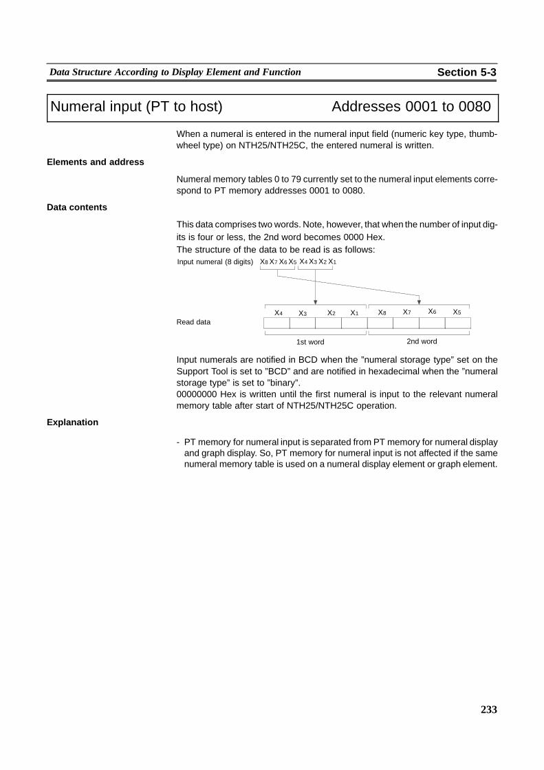
233
Data Structure According to Display Element and Function Section 5-3
Numeral input (PT to host) Addresses 0001 to 0080
When a numeral is entered in the numeral input field (numeric key type, thumb-wheel type) on NTH25/NTH25C, the entered numeral is written.
Elements and address
Numeral memory tables 0 to 79 currently set to the numeral input elements corre-spond to PT memory addresses 0001 to 0080.
Data contents
This data comprises two words. Note, however, that when the number of input dig-its is four or less, the 2nd word becomes 0000 Hex.The structure of the data to be read is as follows:Input numeral (8 digits)
�� ������
1st word
�� ������Read data
2nd word
X4 X3 X2 X1X8 X7 X6 X5
X4 X3 X2 X1 X8 X7 X6 X5
Input numerals are notified in BCD when the ”numeral storage type” set on theSupport Tool is set to ”BCD” and are notified in hexadecimal when the ”numeralstorage type” is set to ”binary”.00000000 Hex is written until the first numeral is input to the relevant numeralmemory table after start of NTH25/NTH25C operation.
Explanation
- PT memory for numeral input is separated from PT memory for numeral displayand graph display. So, PT memory for numeral input is not affected if the samenumeral memory table is used on a numeral display element or graph element.
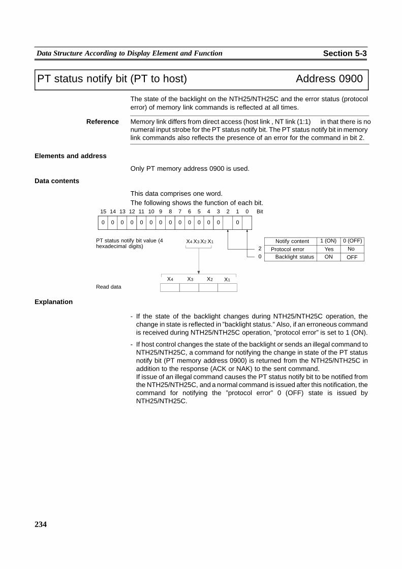
234
Data Structure According to Display Element and Function Section 5-3
PT status notify bit (PT to host) Address 0900
The state of the backlight on the NTH25/NTH25C and the error status (protocolerror) of memory link commands is reflected at all times.
Reference Memory link differs from direct access (host link , NT link (1:1)� in that there is nonumeral input strobe for the PT status notify bit. The PT status notify bit inmemorylink commands also reflects the presence of an error for the command in bit 2.
Elements and address
Only PT memory address 0900 is used.
Data contents
This data comprises one word.The following shows the function of each bit.
ON OFF
00
1415 13 12 11 10 9 8 7 Bit
Notify content 1 (ON) 0 (OFF)
0
6 5 4 3 2 1 0
0
Protocol error Yes No2
Backlight status0
0000000000
PT status notify bit value (4hexadecimal digits)
X4 X3 X2 X1
�� ������Read dataX4 X3 X2 X1
Explanation
- If the state of the backlight changes during NTH25/NTH25C operation, thechange in state is reflected in ”backlight status.” Also, if an erroneous commandis received during NTH25/NTH25C operation, ”protocol error” is set to 1 (ON).
- If host control changes the state of the backlight or sends an illegal command toNTH25/NTH25C, a command for notifying the change in state of the PT statusnotify bit (PT memory address 0900) is returned from the NTH25/NTH25C inaddition to the response (ACK or NAK) to the sent command.If issue of an illegal command causes the PT status notify bit to be notified fromthe NTH25/NTH25C, and a normal command is issued after this notification, thecommand for notifying the ”protocol error” 0 (OFF) state is issued byNTH25/NTH25C.
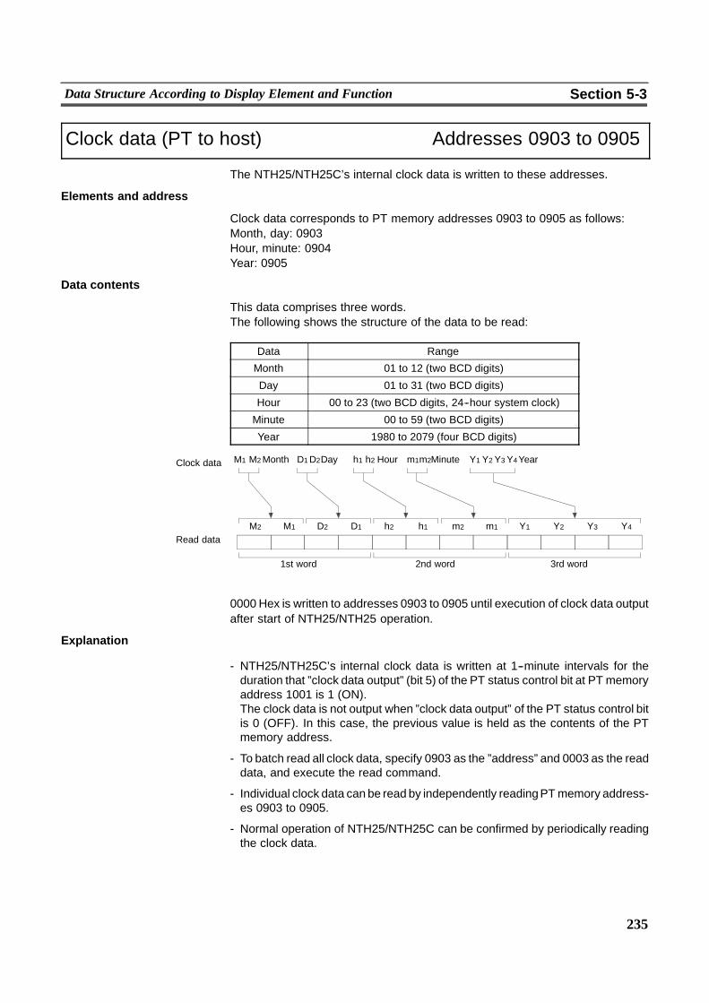
235
Data Structure According to Display Element and Function Section 5-3
Clock data (PT to host) Addresses 0903 to 0905
The NTH25/NTH25C’s internal clock data is written to these addresses.
Elements and address
Clock data corresponds to PT memory addresses 0903 to 0905 as follows:Month, day: 0903Hour, minute: 0904Year: 0905
Data contents
This data comprises three words.The following shows the structure of the data to be read:
Data Range
Month 01 to 12 (two BCD digits)
Day 01 to 31 (two BCD digits)
Hour 00 to 23 (two BCD digits, 24--hour system clock)
Minute 00 to 59 (two BCD digits)
Year 1980 to 2079 (four BCD digits)
Clock data
�� ����
M2 M1 D2 D1
��
2nd word
�� ����
h2 h1 m2 m1
��
3rd word
Read data
M1 M2Month D1D2Day h1 h2 Hour m1m2Minute
�� ����
Y1 Y2 Y3 Y4
��
1st word
Y4YearY3Y2Y1
0000 Hex is written to addresses 0903 to 0905 until execution of clock data outputafter start of NTH25/NTH25 operation.
Explanation
- NTH25/NTH25C’s internal clock data is written at 1--minute intervals for theduration that ”clock data output” (bit 5) of the PT status control bit at PT memoryaddress 1001 is 1 (ON).The clock data is not output when ”clock data output” of the PT status control bitis 0 (OFF). In this case, the previous value is held as the contents of the PTmemory address.
- To batch read all clock data, specify 0903 as the ”address” and 0003 as the readdata, and execute the read command.
- Individual clock data can be read by independently readingPTmemory address-es 0903 to 0905.
- Normal operation of NTH25/NTH25C can be confirmed by periodically readingthe clock data.
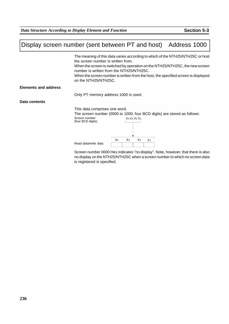
236
Data Structure According to Display Element and Function Section 5-3
Display screen number (sent between PT and host) Address 1000
Themeaning of this data varies according to which of the NTH25/NTH25C or hostthe screen number is written from.When the screen is switched by operation on theNTH25/NTH25C, the newscreennumber is written from the NTH25/NTH25C.When the screen number is written from the host, the specified screen is displayedon the NTH25/NTH25C.
Elements and address
Only PT memory address 1000 is used.
Data contents
This data comprises one word.The screen number (0000 to 1000, four BCD digits) are stored as follows:Screen number(four BCD digits)
Read data/write data
X4 X3 X2 X1
�� ������
X4 X3 X2 X1
Screen number 0000 Hex indicates ”no display”. Note, however, that there is alsono display on the NTH25/NTH25Cwhen a screen number to which no screen datais registered is specified.
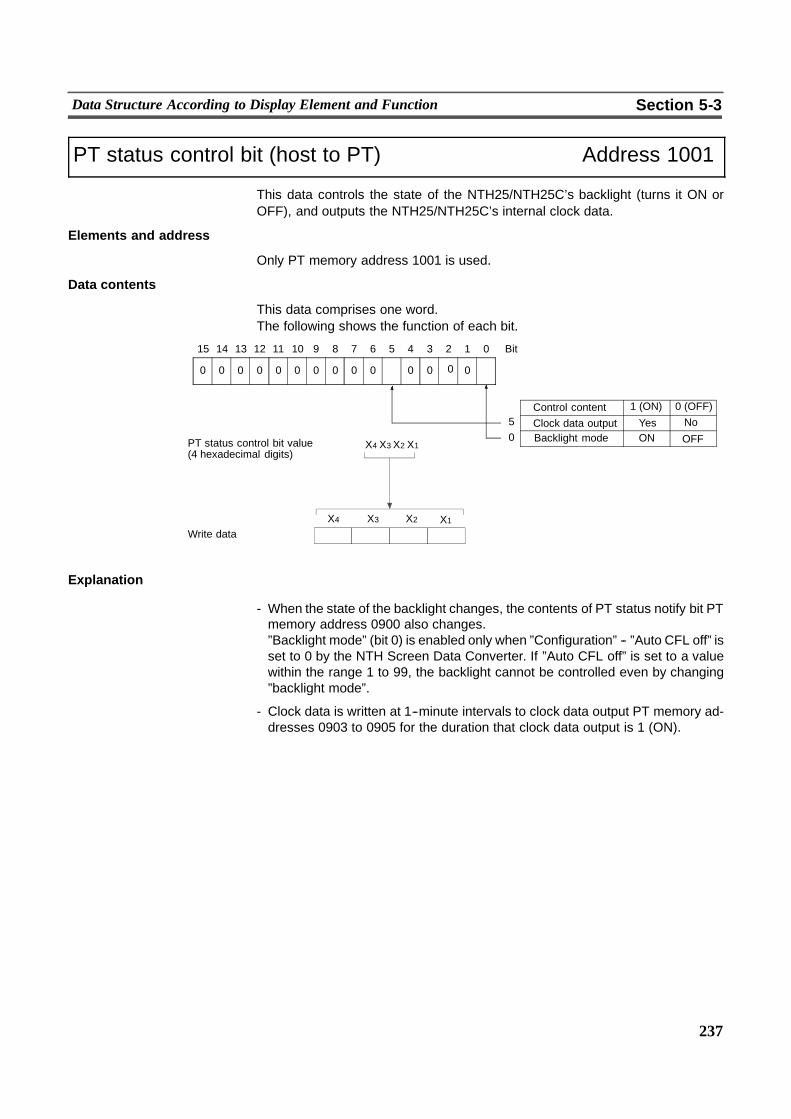
237
Data Structure According to Display Element and Function Section 5-3
PT status control bit (host to PT) Address 1001
This data controls the state of the NTH25/NTH25C’s backlight (turns it ON orOFF), and outputs the NTH25/NTH25C’s internal clock data.
Elements and address
Only PT memory address 1001 is used.
Data contents
This data comprises one word.The following shows the function of each bit.
ON OFF
00
1415 13 12 11 10 9 8 7 Bit
Control content 1 (ON) 0 (OFF)
0
6 5 4 3 2 1 0
0
Clock data output Yes No5
Backlight mode0
00 00000000
PT status control bit value(4 hexadecimal digits)
X4 X3 X2 X1
�� ������Write dataX4 X3 X2 X1
Explanation
- When the state of the backlight changes, the contents of PT status notify bit PTmemory address 0900 also changes.”Backlight mode” (bit 0) is enabled only when ”Configuration” -- ”Auto CFL off” isset to 0 by the NTH Screen Data Converter. If ”Auto CFL off” is set to a valuewithin the range 1 to 99, the backlight cannot be controlled even by changing”backlight mode”.
- Clock data is written at 1--minute intervals to clock data output PT memory ad-dresses 0903 to 0905 for the duration that clock data output is 1 (ON).
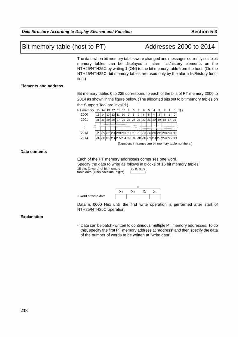
238
Data Structure According to Display Element and Function Section 5-3
Bit memory table (host to PT) Addresses 2000 to 2014
The date when bit memory tables were changed andmessages currently set to bitmemory tables can be displayed in alarm list/history elements on theNTH25/NTH25C by writing 1 (ON) to the bit memory table from the host. (On theNTH25/NTH25C, bit memory tables are used only by the alarm list/history func-tion.)
Elements and address
Bit memory tables 0 to 239 correspond to each of the bits of PT memory 2000 to2014 as shown in the figure below. (The allocated bits set to bit memory tables onthe Support Tool are invalid.)
15 14 13 12 11 10 9 8 7 6 5 4 3 2 1200015 14 13 12 11 10 9 8 7 6 5 4 3 2 1 0 Bit
31 30 29 28 27 26 25 24 23 22 21 20 19 18 172001
238 237 236 235 234 233 232 231 230 229 228 227 226 225 2242014
222 221 220 219 218 217 216 215 214 213 212 211 210 209 2082013
(Numbers in frames are bit memory table numbers.)
239
223
0
16
PT memory
Data contents
Each of the PT memory addresses comprises one word.Specify the data to write as follows in blocks of 16 bit memory tables.16 bits (1 word) of bit memorytable data (4 hexadecimal digits)
X4 X3 X2 X1
�� ������1 word of write dataX4 X3 X2 X1
Data is 0000 Hex until the first write operation is performed after start ofNTH25/NTH25C operation.
Explanation
- Data can be batch--written to continuous multiple PT memory addresses. To dothis, specify the first PT memory address at ”address” and then specify the dataof the number of words to be written at ”write data”.
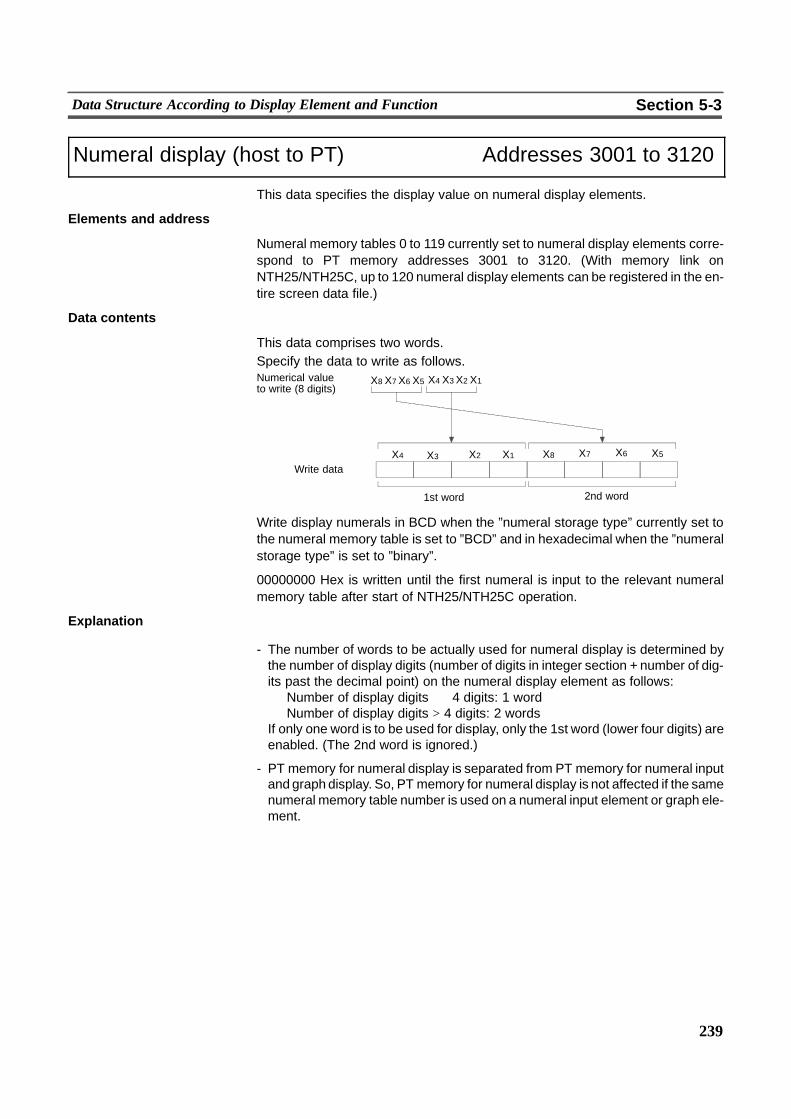
239
Data Structure According to Display Element and Function Section 5-3
Numeral display (host to PT) Addresses 3001 to 3120
This data specifies the display value on numeral display elements.
Elements and address
Numeral memory tables 0 to 119 currently set to numeral display elements corre-spond to PT memory addresses 3001 to 3120. (With memory link onNTH25/NTH25C, up to 120 numeral display elements can be registered in the en-tire screen data file.)
Data contents
This data comprises two words.Specify the data to write as follows.Numerical valueto write (8 digits)
Write data �� ������
1st word
�� ������
2nd word
X4 X3 X2 X1X8 X7 X6 X5
X4 X3 X2 X1 X8 X7 X6 X5
Write display numerals in BCD when the ”numeral storage type” currently set tothe numeral memory table is set to ”BCD” and in hexadecimal when the ”numeralstorage type” is set to ”binary”.
00000000 Hex is written until the first numeral is input to the relevant numeralmemory table after start of NTH25/NTH25C operation.
Explanation
- The number of words to be actually used for numeral display is determined bythe number of display digits (number of digits in integer section + number of dig-its past the decimal point) on the numeral display element as follows:
Number of display digits � 4 digits: 1 wordNumber of display digits > 4 digits: 2 words
If only one word is to be used for display, only the 1st word (lower four digits) areenabled. (The 2nd word is ignored.)
- PT memory for numeral display is separated from PT memory for numeral inputand graph display. So, PT memory for numeral display is not affected if the samenumeral memory table number is used on a numeral input element or graph ele-ment.
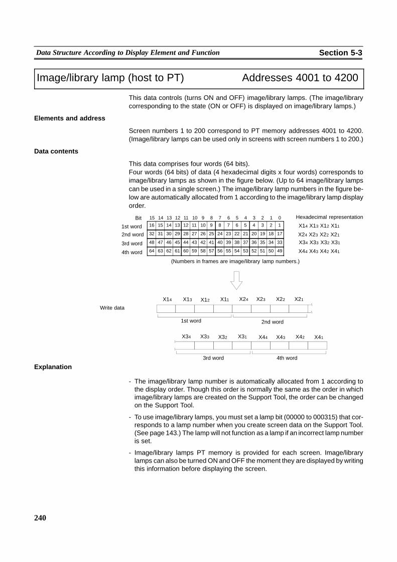
240
Data Structure According to Display Element and Function Section 5-3
Image/library lamp (host to PT) Addresses 4001 to 4200
This data controls (turns ON and OFF) image/library lamps. (The image/librarycorresponding to the state (ON or OFF) is displayed on image/library lamps.)
Elements and address
Screen numbers 1 to 200 correspond to PT memory addresses 4001 to 4200.(Image/library lamps can be used only in screens with screen numbers 1 to 200.)
Data contents
This data comprises four words (64 bits).Four words (64 bits) of data (4 hexadecimal digits x four words) corresponds toimage/library lamps as shown in the figure below. (Up to 64 image/library lampscan be used in a single screen.) The image/library lamp numbers in the figure be-low are automatically allocated from 1 according to the image/library lamp displayorder.
1st word
Write data
16 15 14 13 12 11 10 9 8 7 6 5 4 3 2 11st word
15 14 13 12 11 10 9 8 7 6 5 4 3 2 1 0Bit
32 31 30 29 28 27 26 25 24 23 22 21 20 19 18 17
48 47 46 45 44 43 42 41 40 39 38 37 36 35 34 33
64 63 62 61 60 59 58 57 56 55 54 53 52 51 50 49
(Numbers in frames are image/library lamp numbers.)
X14 X13 X12 X11�Hexadecimal representation
���
4th word3rd word
2nd word
4th word
3rd word
2nd word X24 X23 X22 X21X34 X33 X32 X31
X44 X43 X42 X41
X14 X13 X12 X11 X24 X23 X22 X21
X34 X33 X32 X31 X44 X43 X42 X41
�� ������ ������ ��
�� ������ ������ ��
Explanation
- The image/library lamp number is automatically allocated from 1 according tothe display order. Though this order is normally the same as the order in whichimage/library lamps are created on the Support Tool, the order can be changedon the Support Tool.
- To use image/library lamps, you must set a lamp bit (00000 to 000315) that cor-responds to a lamp number when you create screen data on the Support Tool.(See page 143.) The lamp will not function as a lamp if an incorrect lamp numberis set.
- Image/library lamps PT memory is provided for each screen. Image/librarylamps can also be turned ONandOFF themoment they are displayed bywritingthis information before displaying the screen.
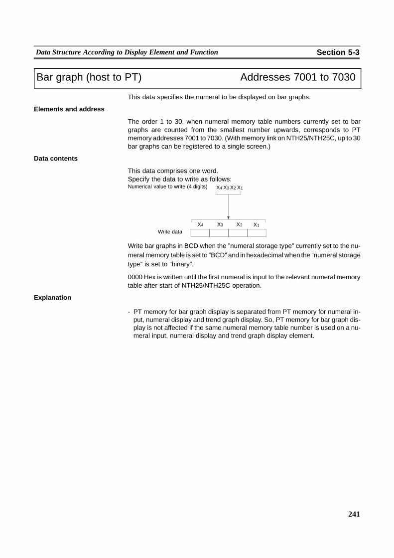
241
Data Structure According to Display Element and Function Section 5-3
Bar graph (host to PT) Addresses 7001 to 7030
This data specifies the numeral to be displayed on bar graphs.
Elements and address
The order 1 to 30, when numeral memory table numbers currently set to bargraphs are counted from the smallest number upwards, corresponds to PTmemory addresses 7001 to 7030. (Withmemory link on NTH25/NTH25C, up to 30bar graphs can be registered to a single screen.)
Data contents
This data comprises one word.Specify the data to write as follows:Numerical value to write (4 digits) X4 X3 X2 X1
�� ������Write dataX4 X3 X2 X1
Write bar graphs in BCD when the ”numeral storage type” currently set to the nu-meralmemory table is set to ”BCD” and inhexadecimal when the ”numeral storagetype” is set to ”binary”.
0000 Hex is written until the first numeral is input to the relevant numeral memorytable after start of NTH25/NTH25C operation.
Explanation
- PT memory for bar graph display is separated from PT memory for numeral in-put, numeral display and trend graph display. So, PT memory for bar graph dis-play is not affected if the same numeral memory table number is used on a nu-meral input, numeral display and trend graph display element.
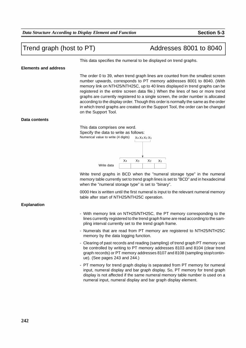
242
Data Structure According to Display Element and Function Section 5-3
Trend graph (host to PT) Addresses 8001 to 8040
This data specifies the numeral to be displayed on trend graphs.
Elements and address
The order 0 to 39, when trend graph lines are counted from the smallest screennumber upwards, corresponds to PT memory addresses 8001 to 8040. (Withmemory link on NTH25/NTH25C, up to 40 lines displayed in trend graphs can beregistered in the entire screen data file.) When the lines of two or more trendgraphs are currently registered to a single screen, the order number is allocatedaccording to the display order. Though this order is normally the same as the orderin which trend graphs are created on the Support Tool, the order can be changedon the Support Tool.
Data contents
This data comprises one word.Specify the data to write as follows:Numerical value to write (4 digits) X4 X3 X2 X1
�� ������Write dataX4 X3 X2 X1
Write trend graphs in BCD when the ”numeral storage type” in the numeralmemory table currently set to trend graph lines is set to ”BCD” and in hexadecimalwhen the ”numeral storage type” is set to ”binary”.
0000 Hex is written until the first numeral is input to the relevant numeral memorytable after start of NTH25/NTH25C operation.
Explanation
- With memory link on NTH25/NTH25C, the PT memory corresponding to thelines currently registered to the trend graph frame are read according to the sam-pling interval currently set to the trend graph frame.
- Numerals that are read from PT memory are registered to NTH25/NTH25Cmemory by the data logging function.
- Clearing of past records and reading (sampling) of trend graph PT memory canbe controlled by writing to PT memory addresses 8103 and 8104 (clear trendgraph records) or PT memory addresses 8107 and 8108 (sampling stop/contin-ue). (See pages 243 and 244.)
- PT memory for trend graph display is separated from PT memory for numeralinput, numeral display and bar graph display. So, PT memory for trend graphdisplay is not affected if the same numeral memory table number is used on anumeral input, numeral display and bar graph display element.
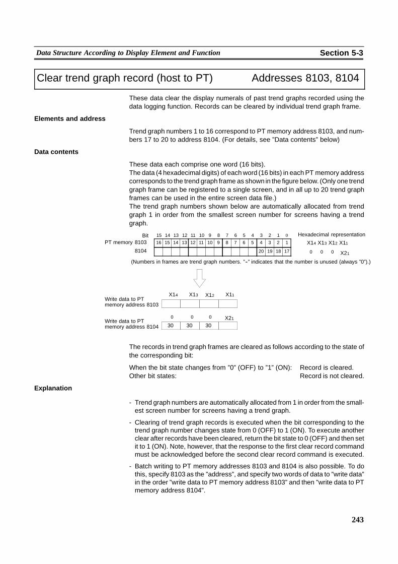
243
Data Structure According to Display Element and Function Section 5-3
Clear trend graph record (host to PT) Addresses 8103, 8104
These data clear the display numerals of past trend graphs recorded using thedata logging function. Records can be cleared by individual trend graph frame.
Elements and address
Trend graph numbers 1 to 16 correspond to PT memory address 8103, and num-bers 17 to 20 to address 8104. (For details, see ”Data contents” below)
Data contents
These data each comprise one word (16 bits).The data (4 hexadecimal digits) of eachword (16 bits) in eachPT memory addresscorresponds to the trend graph frame as shown in the figure below. (Only one trendgraph frame can be registered to a single screen, and in all up to 20 trend graphframes can be used in the entire screen data file.)The trend graph numbers shown below are automatically allocated from trendgraph 1 in order from the smallest screen number for screens having a trendgraph.
Write data to PTmemory address 8103
16 15 14 13 12 11 10 9 8 7 6 5 4 3 2 1810315 14 13 12 11 10 9 8 7 6 5 4 3 2 1 0Bit
� � � � � � � � � � � � 20 19 18 178104
(Numbers in frames are trend graph numbers. ”--” indicates that the number is unused (always ”0”).)
�Hexadecimal representation
0 0 0 X21�PT memory
303030Write data to PTmemory address 8104
X14 X13 X12 X11
0 0 0 X21
X14 X13 X12 X11
�� ������
��
The records in trend graph frames are cleared as follows according to the state ofthe corresponding bit:
When the bit state changes from ”0” (OFF) to ”1” (ON): Record is cleared.Other bit states: Record is not cleared.
Explanation
- Trend graph numbers are automatically allocated from 1 in order from the small-est screen number for screens having a trend graph.
- Clearing of trend graph records is executed when the bit corresponding to thetrend graph number changes state from 0 (OFF) to 1 (ON). To execute anotherclear after records have been cleared, return the bit state to 0 (OFF) and then setit to 1 (ON). Note, however, that the response to the first clear record commandmust be acknowledged before the second clear record command is executed.
- Batch writing to PT memory addresses 8103 and 8104 is also possible. To dothis, specify 8103 as the ”address”, and specify two words of data to ”write data”in the order ”write data to PT memory address 8103” and then ”write data to PTmemory address 8104”.
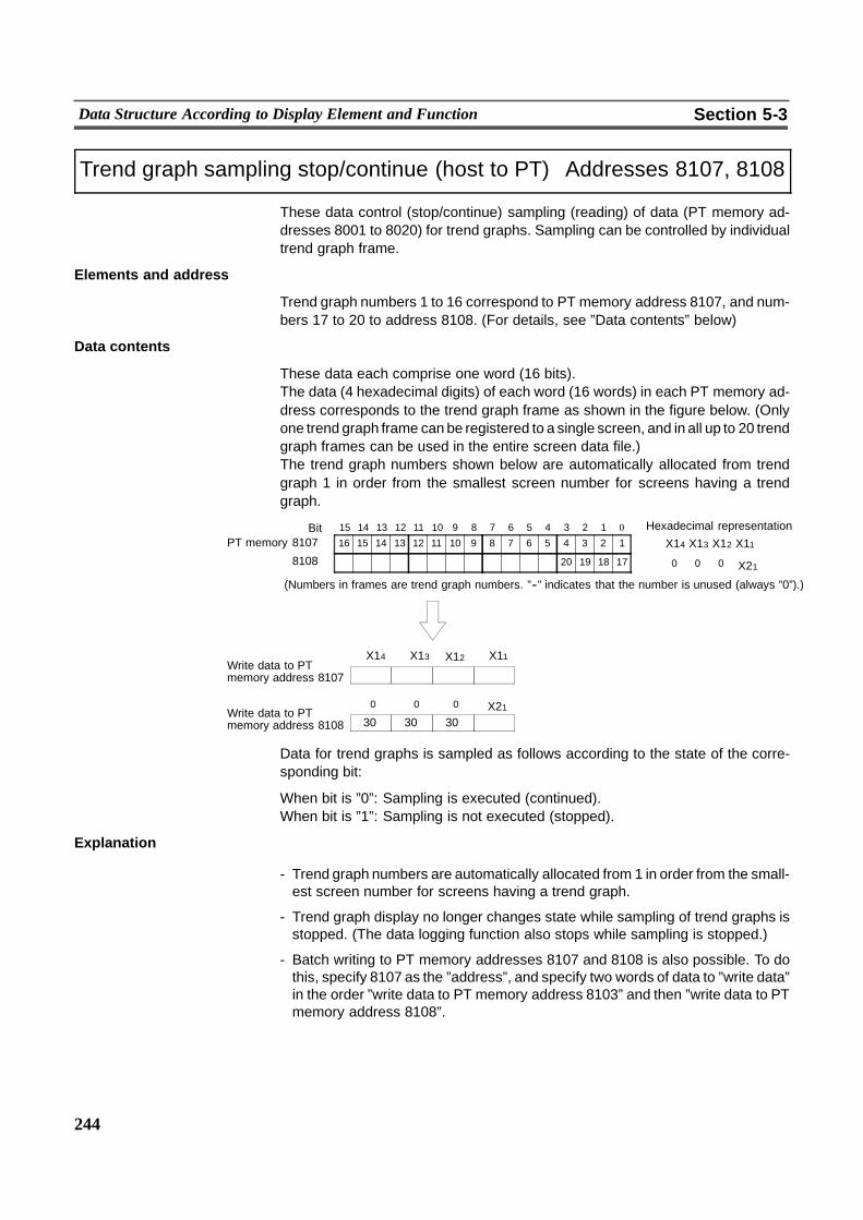
244
Data Structure According to Display Element and Function Section 5-3
Trend graph sampling stop/continue (host to PT) Addresses 8107, 8108
These data control (stop/continue) sampling (reading) of data (PT memory ad-dresses 8001 to 8020) for trend graphs. Sampling can be controlled by individualtrend graph frame.
Elements and address
Trend graph numbers 1 to 16 correspond to PT memory address 8107, and num-bers 17 to 20 to address 8108. (For details, see ”Data contents” below)
Data contents
These data each comprise one word (16 bits).The data (4 hexadecimal digits) of each word (16 words) in each PT memory ad-dress corresponds to the trend graph frame as shown in the figure below. (Onlyone trend graph frame can be registered to a single screen, and in all up to 20 trendgraph frames can be used in the entire screen data file.)The trend graph numbers shown below are automatically allocated from trendgraph 1 in order from the smallest screen number for screens having a trendgraph.
Write data to PTmemory address 8107
16 15 14 13 12 11 10 9 8 7 6 5 4 3 2 1810715 14 13 12 11 10 9 8 7 6 5 4 3 2 1 0Bit
� � � � � � � � � � � � 20 19 18 178108
(Numbers in frames are trend graph numbers. ”--” indicates that the number is unused (always ”0”).)
�Hexadecimal representation
0 0 0 X21�PT memory
303030Write data to PTmemory address 8108
X14 X13 X12 X11
0 0 0 X21
X14 X13 X12 X11
�� ������
��
Data for trend graphs is sampled as follows according to the state of the corre-sponding bit:
When bit is ”0”: Sampling is executed (continued).When bit is ”1”: Sampling is not executed (stopped).
Explanation
- Trend graph numbers are automatically allocated from 1 in order from the small-est screen number for screens having a trend graph.
- Trend graph display no longer changes state while sampling of trend graphs isstopped. (The data logging function also stops while sampling is stopped.)
- Batch writing to PT memory addresses 8107 and 8108 is also possible. To dothis, specify 8107 as the ”address”, and specify two words of data to ”write data”in the order ”write data to PT memory address 8103” and then ”write data to PTmemory address 8108”.
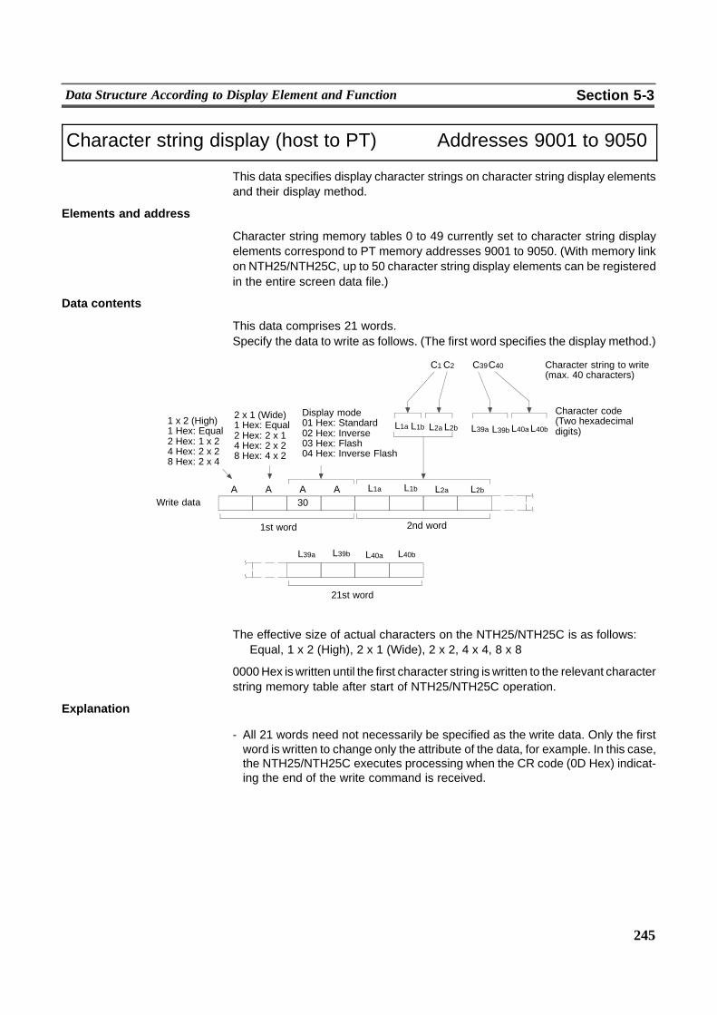
245
Data Structure According to Display Element and Function Section 5-3
Character string display (host to PT) Addresses 9001 to 9050
This data specifies display character strings on character string display elementsand their display method.
Elements and address
Character string memory tables 0 to 49 currently set to character string displayelements correspond to PT memory addresses 9001 to 9050. (With memory linkon NTH25/NTH25C, up to 50 character string display elements can be registeredin the entire screen data file.)
Data contents
This data comprises 21 words.Specify the data to write as follows. (The first word specifies the display method.)
L1a
Character code(Two hexadecimaldigits)
30A A A A
Write data
Character string to write(max. 40 characters)
� C39C40C1C2
�
Display mode01 Hex: Standard02 Hex: Inverse03 Hex: Flash04 Hex: Inverse Flash
1 x 2 (High)1 Hex: Equal2 Hex: 1 x 24 Hex: 2 x 28 Hex: 2 x 4
���
2 x 1 (Wide)1 Hex: Equal2 Hex: 2 x 14 Hex: 2 x 28 Hex: 4 x 2
�
��
1st word 2nd word
21st word
�� ������
������ �� ������
L40bL40aL39bL39aL2bL2aL1b
L1a L2bL2aL1b
L40bL40aL39bL39a
The effective size of actual characters on the NTH25/NTH25C is as follows:Equal, 1 x 2 (High), 2 x 1 (Wide), 2 x 2, 4 x 4, 8 x 8
0000Hex is written until the first character string is written to the relevant characterstring memory table after start of NTH25/NTH25C operation.
Explanation
- All 21 words need not necessarily be specified as the write data. Only the firstword is written to change only the attribute of the data, for example. In this case,the NTH25/NTH25C executes processing when the CR code (0D Hex) indicat-ing the end of the write command is received.
246
Data Structure According to Display Element and Function Section 5-3
- When 0000 Hex is written to one word of data as a character string, theNTH25/NTH25C treats this as the end of the character string, and ignores sub-sequent data. Note, however, that the display is not cleared when the characterstring display is updated on the NTH25/NTH25C. So, the previously displayedcharacter string may still be remaining on screen behind the data. If the numberof display characters is not fixed, fill the remaining areawith standard spaces (20Hex), and write 0000 Hex last of all to indicate the end of the character string.
- The origin from where the character is extended is the top left corner coordinateof the character string.
- If a newly specified character string extends out of the right of theNTH25/NTH25C’s screen, it will be carriage--fed at that point, and displayedfrom the left edge of the next line (position lowered by the height of the charac-ter).If the character string extends out of the bottom of the screen, it will be displayedfrom the top left corner of the screen.
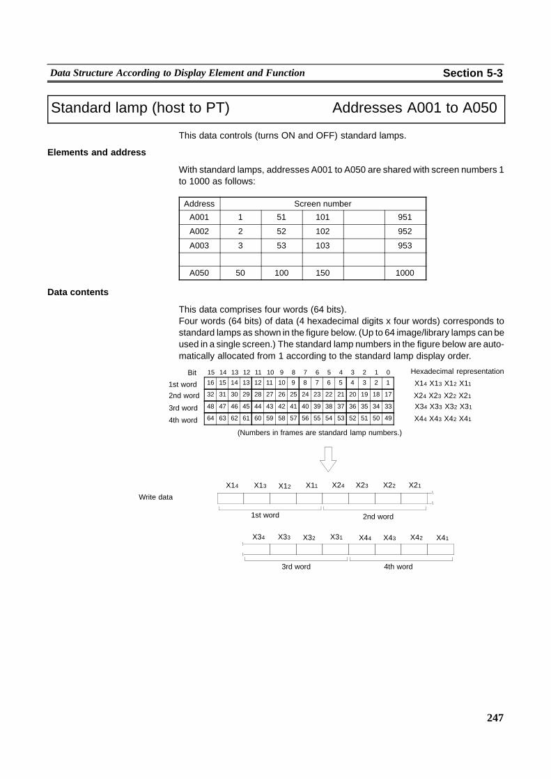
� � � ��
247
Data Structure According to Display Element and Function Section 5-3
Standard lamp (host to PT) Addresses A001 to A050
This data controls (turns ON and OFF) standard lamps.
Elements and address
With standard lamps, addresses A001 to A050 are shared with screen numbers 1to 1000 as follows:
Address Screen number
A001 1 51 101 � 951
A002 2 52 102 � 952
A003 3 53 103 � 953
A050 50 100 150 � 1000
Data contents
This data comprises four words (64 bits).Four words (64 bits) of data (4 hexadecimal digits x four words) corresponds tostandard lamps as shown in the figure below. (Up to 64 image/library lamps can beused in a single screen.) The standard lamp numbers in the figure below are auto-matically allocated from 1 according to the standard lamp display order.
1st word
Write data
16 15 14 13 12 11 10 9 8 7 6 5 4 3 2 11st word
15 14 13 12 11 10 9 8 7 6 5 4 3 2 1 0Bit
32 31 30 29 28 27 26 25 24 23 22 21 20 19 18 17
48 47 46 45 44 43 42 41 40 39 38 37 36 35 34 33
64 63 62 61 60 59 58 57 56 55 54 53 52 51 50 49
(Numbers in frames are standard lamp numbers.)
X14 X13 X12 X11�Hexadecimal representation
���
4th word3rd word
2nd word
4th word
3rd word
2nd word X24 X23 X22 X21X34 X33 X32 X31
X44 X43 X42 X41
X14 X13 X12 X11 X24 X23 X22 X21
X34 X33 X32 X31 X44 X43 X42 X41
�� ������ ������ ��
�� ������ ������ ��
248
Data Structure According to Display Element and Function Section 5-3
Explanation
- The standard lamp number is automatically allocated from 1 according to thedisplay order. Though this order is normally the same as the order in which stan-dard lamps are created on the Support Tool, the order can be changed on theSupport Tool.
- 50 screens’worth of standard lampPTmemory is provided. Standard lamps canalso be turned ON and OFF the moment they are displayed by writing this infor-mation before displaying the screen.
- To use standard lamps, you must set a lamp bit (00000 to 000315) that corre-sponds to a lamp number when you create screen data on the Support Tool.(See page 143.) The lamp will not function as a lamp if an incorrect lamp numberis set.
249
SECTION 6NTH Screen Data Converter
This section describes the functions of NTH Screen Data Converter and how to use these functions.
6-1 Outline of NTH Screen Data Converter 250. . . . . . . . . . . . . . . . . . . . . . . . . . . . . . . . . . . . . . . . . . .6-1-1 What is NTH Screen Data Converter? 250. . . . . . . . . . . . . . . . . . . . . . . . . . . . . . . . . . . . . .6-1-2 Functions of NTH Screen Data Converter 251. . . . . . . . . . . . . . . . . . . . . . . . . . . . . . . . . . . .
6-2 Setting Up NTH Screen Data Converter 252. . . . . . . . . . . . . . . . . . . . . . . . . . . . . . . . . . . . . . . . . . .6-2-1 Equipment Needed To Use NTH Screen Data Converter 252. . . . . . . . . . . . . . . . . . . . . . . .6-2-2 How to Install NTH Screen Data Converter 253. . . . . . . . . . . . . . . . . . . . . . . . . . . . . . . . . .
6-3 Operating NTH Screen Data Converter 259. . . . . . . . . . . . . . . . . . . . . . . . . . . . . . . . . . . . . . . . . . .6-3-1 Starting Up and Exiting NTH Screen Data Converter 259. . . . . . . . . . . . . . . . . . . . . . . . . .6-3-2 Configuration 260. . . . . . . . . . . . . . . . . . . . . . . . . . . . . . . . . . . . . . . . . . . . . . . . . . . . . . . . . .6-3-3 Function key settings 265. . . . . . . . . . . . . . . . . . . . . . . . . . . . . . . . . . . . . . . . . . . . . . . . . . . .6-3-4 Window control area setting 269. . . . . . . . . . . . . . . . . . . . . . . . . . . . . . . . . . . . . . . . . . . . . .6-3-5 Trend graph control area settings 271. . . . . . . . . . . . . . . . . . . . . . . . . . . . . . . . . . . . . . . . . .6-3-6 Transmitting Screen Data 273. . . . . . . . . . . . . . . . . . . . . . . . . . . . . . . . . . . . . . . . . . . . . . . .

250
Outline of NTH Screen Data Converter Section 6-1
6-1 Outline of NTH Screen Data Converter
6-1-1 What is NTH Screen Data Converter?The NTH25/NTH25C cannot be selected on the Support Tool as PT models. Tospecify the screen data for use on the NTH25/NTH25C, you must specify the PTmodel as follows:
NTH25: PT model ”NT31”NTH25C: PT model ”NT31C”
However, the functions and data sizes of the NT31/NT31C differ from those of theNTH25/NTH25C. So, the screen data created on the Support Tool for use on theNT31/NT31Cmust be converted to screen data for use on the NTH25/NTH25C byNTH Screen Data Converter before it is sent to the NTH25/NTH25C.On NTH Screen Data Converter, you can make settings specific to theNTH25/NTH25C.
SupportTool
Screen data file(for NT31/NT31C)
NTH ScreenData Converter NTH25/NTH25C
Personal Computer
Create/savescreen data(mmi format).
Read/set upscreen data.
Conversion/transmission
Reference - NTH Screen Data Converter can be executed independently of the SupportTool. So, it need not be installed on the same personal computer as the SupportTool. In this case, however, move the screen data file saved inmmi format to thepersonal computer running NTHScreen DataConverter so that the data can beread by NTH Screen Data Converter.
- The screen data currently registered on the NTH25/NTH25C cannot be read byNTH Screen Data Converter and the Support Tool.
251
Outline of NTH Screen Data Converter Section 6-1
6-1-2 Functions of NTH Screen Data ConverterNTH Screen Data Converter has the following functions:
! Reading of screen data files
The screen data file for use on the NT31/NT31C that was created using NT Se-ries Support Tool for Windows95/98 (Ver.3.0) is read.Note, however, that only mmi format files can be read. The screen data to beread by NTH Screen Data Converter and transferred to NTH25/NTH25C mustbe saved in the mmi format.Screen data containing functions that are not supported on theNTH25/NTH25Csometimes cannot be read.
! Settings for the NTH25/NTH25C
The following items are set as NTH25/NTH25C--specific settings:
[Configuration]Backlight auto OFF timeCommunications method (host link/NT link (1:1)/memory link (NTH protocol))Communications conditions with the hostHost PC type
[Function key setting]Set the notification method of function switches and allocated bits and words forfunction switches.
[Window control area setting]Set the word to be used for manipulating window functions.
[Trend graph control area setting]Set the area for controlling (sampling stop/continue, clear records) trend graphs.
! Screen data conversion
The screen data created on the Support Tool for use on theNT31/NT31C is con-verted for use on the NTH25/NTH25C.During conversion, functions that are not supported on the NTH25/NTH25C,out--of--range bit and word settings, and elements exceeding the maximum per-missible number of elements are invalid and deleted from the screen data file.
Reference When invalid settings or elements are deleted, messages and error logs are notdisplayed on NTH Screen Data Converter. When creating screens for theNTH25/NTH25C, observe restrictions such as the maximum permissible numberof elements, and check these elements on theNTH25/NTH25C screen after send-ing them to the NTH25/NTH25C.
252
Setting Up NTH Screen Data Converter Section 6-2
! Sending (writing) screen data to the NTH25/NTH25C
After the settings are made for the NTH25/NTH25C and screen data is con-verted for use on the NTH25/NTH25C, the screen data is sent to theNTH25/NTH25C.The NTH25/NTH25C must be set to the screen send mode before the screendata is sent to the NTH25/NTH25C.For details on how to enter the screen sendmode, seeSection 3--4 ”Transmittingthe Screen Data” on page 65.
6-2 Setting Up NTH Screen Data Converter
6-2-1 Equipment Needed To Use NTH Screen Data ConverterPrepare the following equipment to use NTH Screen Data Converter:
Hardware
! Recommended CPU
Pentium 100 MHz or faster
! Personal computer
Use an IBM personal computer or 100%compatible machine capable of runningMicrosoft Windows95 or Microsoft Windows98.
An RS--232C port capable of communications at a baud rate of 19,200 bps orhigher must be allocated to one of ports COM1 to COM4 to send screen data tothe NTH25/NTH25C.
! RAM
At least 16 MB
! Free area in hard disk
At least 5 MB
! CD ROM drive
At least one drive is required to install NTH Screen Data Converter.
! Display
VGA compatible display
! Mouse
Serial mouse or bus mouse
Operating system
! Microsoft Windows95 or Microsoft Windows98
Windows3.1, WindowsNT and WindowsNT4.0 are not supported.

253
Setting Up NTH Screen Data Converter Section 6-2
6-2-2 How to Install NTH Screen Data ConverterInstall NTH Screen Data Converter on the hard disk.To install NTH Screen Data Converter, execute the installation program providedwith the NTH25/NTH25C.
Reference When you specify ”Custom” as the setup method, you can select the requireditems to install from the following files:-- Program Files (NTH Screen Data Converter application)-- Ddata Files (PC information files)
Data cannot be converted successfully without ”Ddata Files”. Normally, be sure toinstall all of these files.
Basic installation operation
The following buttons are displayed during installation:
:
Clicking on this button confirms the settings in the currently displayed window anddisplays the next window.
:
Clicking on this button cancels the settings in the currently displayed window anddisplays the previous window.
:
Clicking on this button closes the currently displayed window. The status currentlyset in the window is canceled.If you click this button in the installation window, you can cancel installation. In thiscase, a cancel confirmation message appears on screen.
:
Clicking on this button displays the actual folder configuration as a tree. In this dis-play, you can select the folder to install NTH Screen Data Converter to.
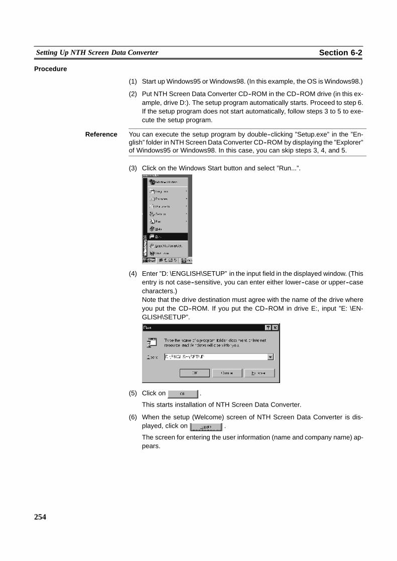
254
Setting Up NTH Screen Data Converter Section 6-2
Procedure
(1) Start upWindows95 or Windows98. (In this example, the OS isWindows98.)
(2) Put NTH Screen Data Converter CD--ROM in the CD--ROM drive (in this ex-ample, drive D:). The setup program automatically starts. Proceed to step 6.If the setup program does not start automatically, follow steps 3 to 5 to exe-cute the setup program.
Reference You can execute the setup program by double--clicking ”Setup.exe” in the ”En-glish” folder in NTH Screen Data Converter CD--ROM by displaying the ”Explorer”of Windows95 or Windows98. In this case, you can skip steps 3, 4, and 5.
(3) Click on the Windows Start button and select ”Run...”.
(4) Enter ”D: \ENGLISH\SETUP” in the input field in the displayed window. (Thisentry is not case--sensitive, you can enter either lower--case or upper--casecharacters.)Note that the drive destination must agree with the name of the drive whereyou put the CD--ROM. If you put the CD--ROM in drive E:, input ”E: \EN-GLISH\SETUP”.
(5) Click on .
This starts installation of NTH Screen Data Converter.
(6) When the setup (Welcome) screen of NTH Screen Data Converter is dis-played, click on .
The screen for entering the user information (name and company name) ap-pears.
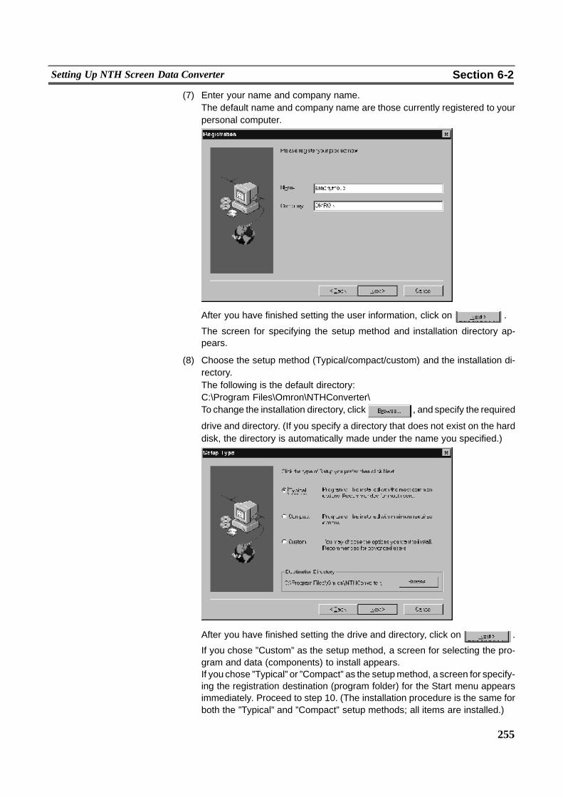
255
Setting Up NTH Screen Data Converter Section 6-2
(7) Enter your name and company name.The default name and company name are those currently registered to yourpersonal computer.
After you have finished setting the user information, click on .
The screen for specifying the setup method and installation directory ap-pears.
(8) Choose the setup method (Typical/compact/custom) and the installation di-rectory.The following is the default directory:C:\Program Files\Omron\NTHConverter\To change the installation directory, click , and specify the required
drive and directory. (If you specify a directory that does not exist on the harddisk, the directory is automatically made under the name you specified.)
After you have finished setting the drive and directory, click on .
If you chose ”Custom” as the setup method, a screen for selecting the pro-gram and data (components) to install appears.If you chose ”Typical” or ”Compact” as the setupmethod, a screen for specify-ing the registration destination (program folder) for the Start menu appearsimmediately. Proceed to step 10. (The installation procedure is the same forboth the ”Typical” and ”Compact” setup methods; all items are installed.)
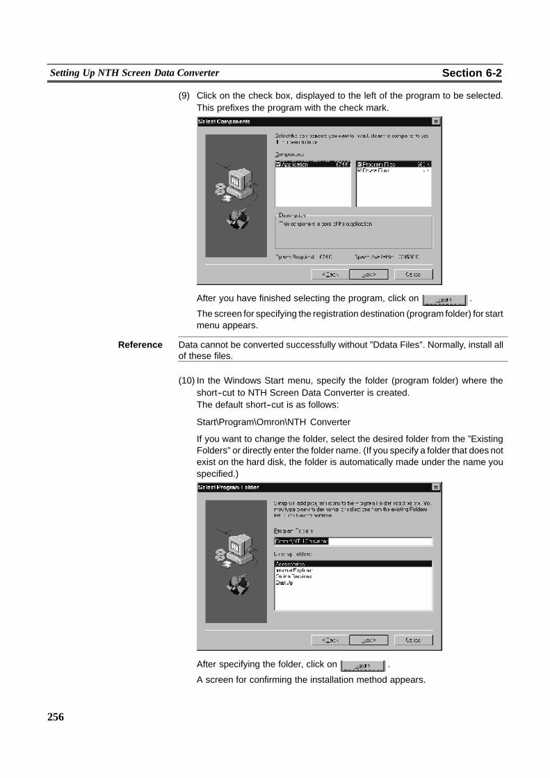
256
Setting Up NTH Screen Data Converter Section 6-2
(9) Click on the check box, displayed to the left of the program to be selected.This prefixes the program with the check mark.
After you have finished selecting the program, click on .
The screen for specifying the registration destination (program folder) for startmenu appears.
Reference Data cannot be converted successfully without ”Ddata Files”. Normally, install allof these files.
(10) In the Windows Start menu, specify the folder (program folder) where theshort--cut to NTH Screen Data Converter is created.The default short--cut is as follows:
Start\Program\Omron\NTH Converter
If you want to change the folder, select the desired folder from the ”ExistingFolders” or directly enter the folder name. (If you specify a folder that does notexist on the hard disk, the folder is automatically made under the name youspecified.)
After specifying the folder, click on .
A screen for confirming the installation method appears.
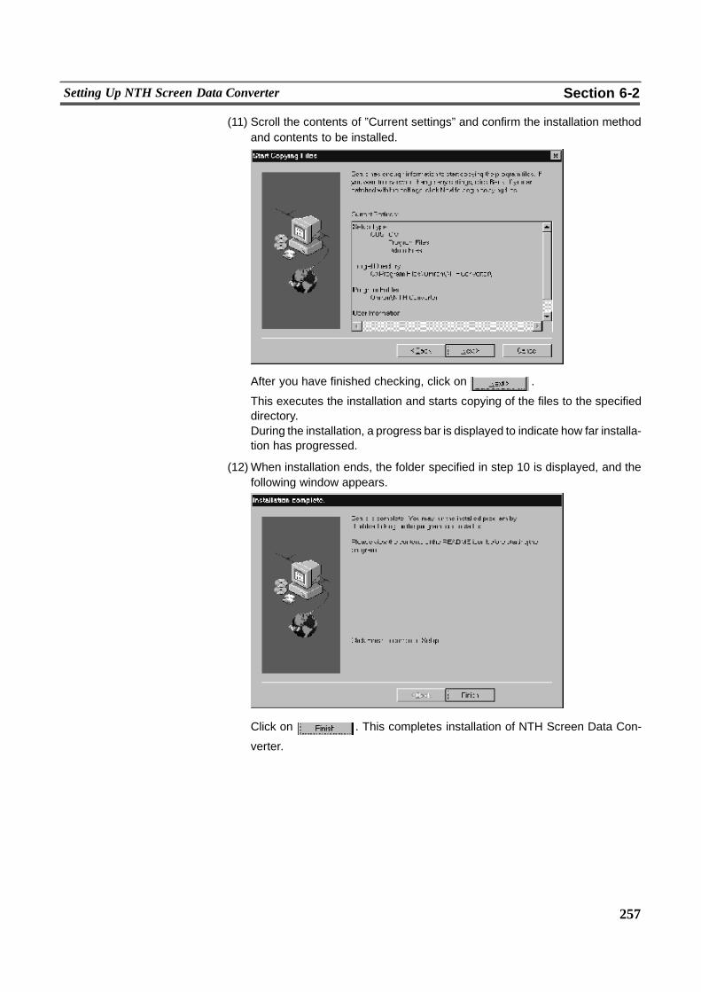
257
Setting Up NTH Screen Data Converter Section 6-2
(11) Scroll the contents of ”Current settings” and confirm the installation methodand contents to be installed.
After you have finished checking, click on .
This executes the installation and starts copying of the files to the specifieddirectory.During the installation, a progress bar is displayed to indicate how far installa-tion has progressed.
(12)When installation ends, the folder specified in step 10 is displayed, and thefollowing window appears.
Click on . This completes installation of NTH Screen Data Con-
verter.
258
Setting Up NTH Screen Data Converter Section 6-2
Uninstall
The Uninstaller (uninstall software) is not provided with NTH Screen Data Con-verter.If NTH Screen Data Converter is no longer required, follow the procedure below todelete NTH Screen Data Converter files and installation information. (If the samefolder as NTH Screen Data Converter contains other files in addition to those thatwere copiedwhenNTHScreenDataConverter was installed, these fileswill not bedeleted and remain in the folder after NTH Screen Data Converter is uninstalled.)
(1) Select theWindows [Start] button and then select [Settings] -- [Control Panel].The Control Panel window appears.
(2) Double--click [Add/Remove Programs].
(3) Select ”NTHConverter” from the list of applications currently displayed in the[Setup and Delete] page, and click [Add/Remove].The confirmation message for removing the files appears.
(4) Click [Yes].From here on, follow the on--screen instructions.
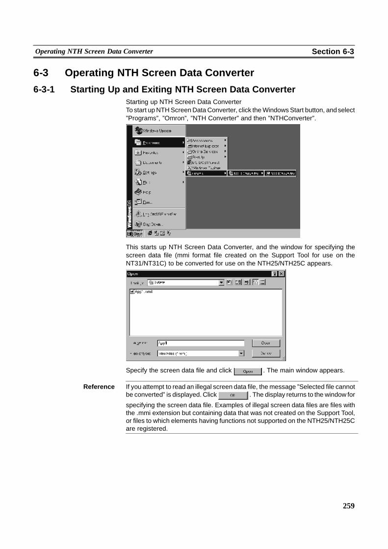
259
Operating NTH Screen Data Converter Section 6-3
6-3 Operating NTH Screen Data Converter
6-3-1 Starting Up and Exiting NTH Screen Data ConverterStarting up NTH Screen Data ConverterTo start upNTHScreenDataConverter, click theWindowsStart button, andselect”Programs”, ”Omron”, ”NTH Converter” and then ”NTHConverter”.
This starts up NTH Screen Data Converter, and the window for specifying thescreen data file (mmi format file created on the Support Tool for use on theNT31/NT31C) to be converted for use on the NTH25/NTH25C appears.
Specify the screen data file and click . The main window appears.
Reference If you attempt to read an illegal screen data file, the message ”Selected file cannotbe converted” is displayed. Click . The display returns to the window for
specifying the screen data file. Examples of illegal screen data files are files withthe .mmi extension but containing data that was not created on the Support Tool,or files to which elements having functions not supported on the NTH25/NTH25Care registered.
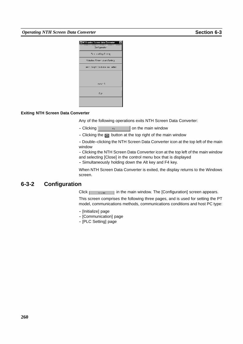
260
Operating NTH Screen Data Converter Section 6-3
Exiting NTH Screen Data Converter
Any of the following operations exits NTH Screen Data Converter:
-- Clicking on the main window
-- Clicking the button at the top right of the main window
-- Double--clicking the NTH Screen Data Converter icon at the top left of the mainwindow-- Clicking the NTH Screen Data Converter icon at the top left of the main windowand selecting [Close] in the control menu box that is displayed-- Simultaneously holding down the Alt key and F4 key.
When NTH Screen Data Converter is exited, the display returns to the Windowsscreen.
6-3-2 ConfigurationClick in the main window. The [Configuration] screen appears.
This screen comprises the following three pages, and is used for setting the PTmodel, communications methods, communications conditions and host PC type:
-- [Initialize] page-- [Communication] page-- [PLC Setting] page
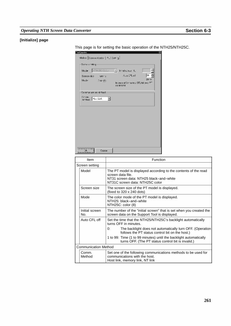
261
Operating NTH Screen Data Converter Section 6-3
[Initialize] page
This page is for setting the basic operation of the NTH25/NTH25C.
Item Function
Screen setting
Model The PT model is displayed according to the contents of the readscreen data file.NT31 screen data: NTH25 black--and--whiteNT31C screen data: NTH25C color
Screen size The screen size of the PT model is displayed.(fixed to 320 x 240 dots)
Mode The color mode of the PT model is displayed.NTH25: black--and--whiteNTH25C: color (8)
Initial screenNo.
The number of the ”initial screen” that is set when you created thescreen data on the Support Tool is displayed.
Auto CFL off Set the time that the NTH25/NTH25C’s backlight automaticallyturns OFF in minutes.0: The backlight does not automatically turn OFF. (Operation
follows the PT status control bit on the host.)1 to 99: Time (1 to 99 minutes) until the backlight automatically
turns OFF. (The PT status control bit is invalid.)
Communication Method
Comm.Method
Set one of the following communications methods to be used forcommunications with the host.Host link, memory link, NT link

262
Operating NTH Screen Data Converter Section 6-3
! About the Backlight Auto OFF Function (Auto CFL off function)
The NTH25/NTH25C is provided with the backlight auto OFF function. Thisfunction automatically turns the NTH25/NTH25C’s backlight OFF when it is notoperated for a fixed period of time.Using this function allows you to extend the backlight’s service life.To enable use of the auto backlight OFF function, set ”Auto CFL off” to a valuewithin the range 1 to 99 (number of minutes until the backlight automaticallyturns OFF). At this setting, the PT status control bit ”backlight mode” (bit 0) isdisabled.To disable use of the auto backlight OFF function, set ”Auto CFL off” to 0. At thissetting, the PT status control bit ”backlight mode” (bit 0) is enabled.
When the backlight autoOFF function is activated and the backlight is turnedOFF,the backlight can be turned ON again by one of the following operations:
-- Pressing a function switch-- Touching the touch panel-- Screen switching from the host
If you press a touch switch while the backlight is OFF as a result of activation of thebacklight auto OFF function, only relighting of the backlight will be executed; thefunction of the switch (e.g. notification to host or screen switching) is not executed.(When a function switch is pressed, notification of the function switch’s state isalso executed.)
Reference - If the backlight is turned OFF by manipulating the PT status control bit with”Auto CFL off” set to 0, the backlight can be turned back ON only by changingthe PT status control bit ”backlight mode” (bit 0) state to 1 (ON). (It cannot beturned back ON by the methods described in the previous paragraph when thebacklight auto OFF function is activated.)
- In its default state, the contents of each of the areas on the PC are 0. So, the PTstatus control bit ”backlight mode” (bit 0) also is 0 (OFF). When theNTH25/NTH25C is connected with ”Auto CFL off” set to 0, the backlight will re-main OFF.
[Communication] page
This page is for setting the communications conditions with the host.For details on setting the communications conditions on the host, see ”2--5 ”Con-necting to the Host”.
Reference - The communications conditions on NTH Screen Data Converter must be set tothe same settings as on the host.
- When ”Comm. Method” in the [Configuration] page is set to [NT Link], the com-munications conditions cannot be set.When ”Comm. Method” is set to [Host Link], be sure to set the following commu-nications conditions:Stop bit: 2Data length: 7Parity: even
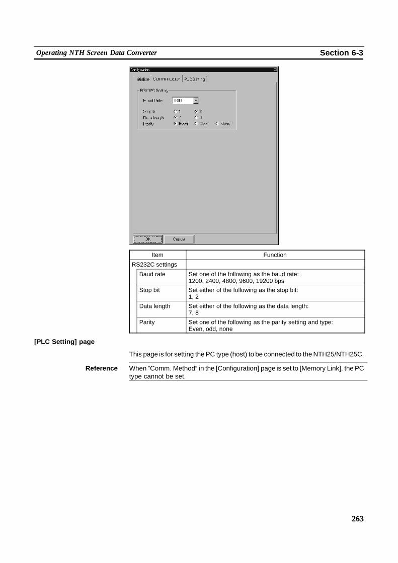
263
Operating NTH Screen Data Converter Section 6-3
Item Function
RS232C settings
Baud rate Set one of the following as the baud rate:1200, 2400, 4800, 9600, 19200 bps
Stop bit Set either of the following as the stop bit:1, 2
Data length Set either of the following as the data length:7, 8
Parity Set one of the following as the parity setting and type:Even, odd, none
[PLC Setting] page
This page is for setting the PC type (host) to be connected to theNTH25/NTH25C.
Reference When ”Comm. Method” in the [Configuration] page is set to [Memory Link], the PCtype cannot be set.
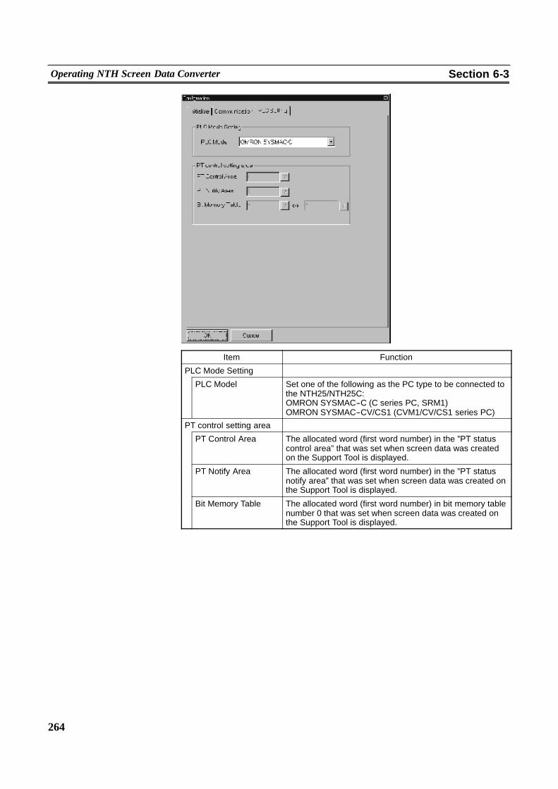
264
Operating NTH Screen Data Converter Section 6-3
Item Function
PLC Mode Setting
PLC Model Set one of the following as the PC type to be connected tothe NTH25/NTH25C:OMRON SYSMAC--C (C series PC, SRM1)OMRON SYSMAC--CV/CS1 (CVM1/CV/CS1 series PC)
PT control setting area
PT Control Area The allocated word (first word number) in the ”PT statuscontrol area” that was set when screen data was createdon the Support Tool is displayed.
PT Notify Area The allocated word (first word number) in the ”PT statusnotify area” that was set when screen data was created onthe Support Tool is displayed.
Bit Memory Table The allocated word (first word number) in bit memory tablenumber 0 that was set when screen data was created onthe Support Tool is displayed.
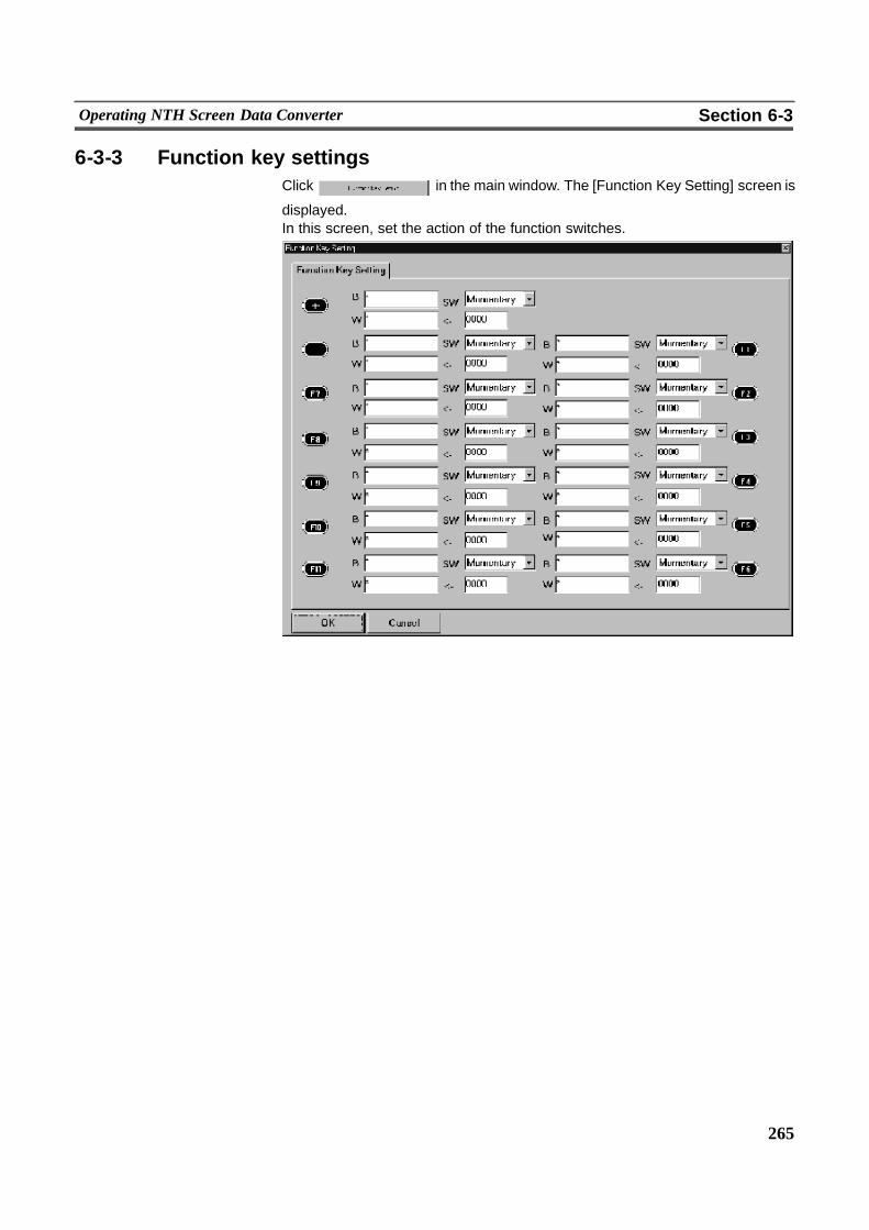
265
Operating NTH Screen Data Converter Section 6-3
6-3-3 Function key settingsClick in the main window. The [Function Key Setting] screen is
displayed.In this screen, set the action of the function switches.
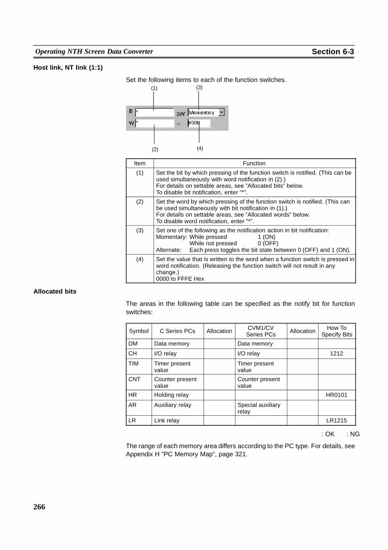
266
Operating NTH Screen Data Converter Section 6-3
Host link, NT link (1:1)
Set the following items to each of the function switches.
(2) (4)
(1) (3)
Item Function
(1) Set the bit by which pressing of the function switch is notified. (This can beused simultaneously with word notification in (2).)For details on settable areas, see ”Allocated bits” below.To disable bit notification, enter ”*”.
(2) Set the word by which pressing of the function switch is notified. (This canbe used simultaneously with bit notification in (1).)For details on settable areas, see ”Allocated words” below.To disable word notification, enter ”*”.
(3) Set one of the following as the notification action in bit notification:Momentary: While pressed 1 (ON)
While not pressed 0 (OFF)Alternate: Each press toggles the bit state between 0 (OFF) and 1 (ON).
(4) Set the value that is written to the word when a function switch is pressed inword notification. (Releasing the function switch will not result in anychange.)0000 to FFFE Hex
Allocated bits
The areas in the following table can be specified as the notify bit for functionswitches:
Symbol C Series PCs Allocation CVM1/CVSeries PCs Allocation How To
Specify Bits
DM Data memory � Data memory � �CH I/O relay � I/O relay � 1212
TIM Timer presentvalue
� Timer presentvalue
� �
CNT Counter presentvalue
� Counter presentvalue
� �
HR Holding relay � � � HR0101
AR Auxiliary relay � Special auxiliaryrelay
� �
LR Link relay � � � LR1215
� : OK � : NG
The range of each memory area differs according to the PC type. For details, seeAppendix H ”PC Memory Map”, page 321.
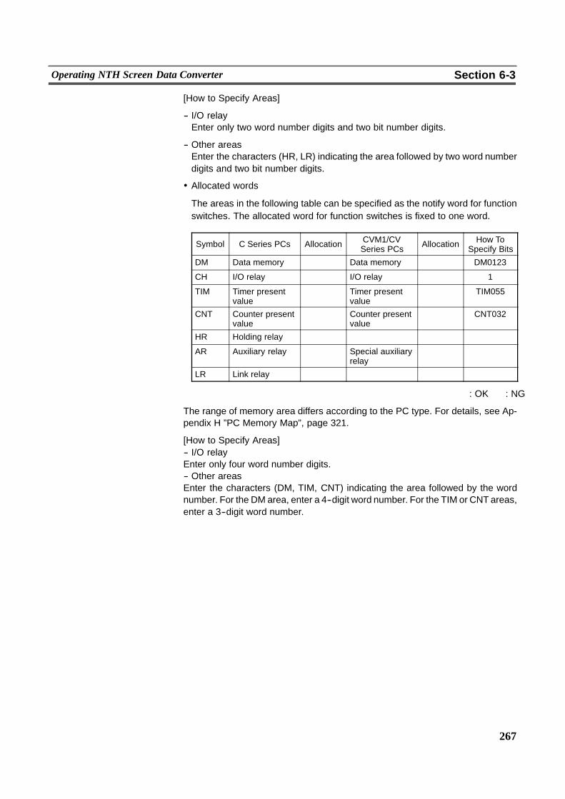
267
Operating NTH Screen Data Converter Section 6-3
[How to Specify Areas]
-- I/O relayEnter only two word number digits and two bit number digits.
-- Other areasEnter the characters (HR, LR) indicating the area followed by two word numberdigits and two bit number digits.
! Allocated words
The areas in the following table can be specified as the notify word for functionswitches. The allocated word for function switches is fixed to one word.
Symbol C Series PCs Allocation CVM1/CVSeries PCs Allocation How To
Specify Bits
DM Data memory � Data memory � DM0123
CH I/O relay � I/O relay � 1
TIM Timer presentvalue
� Timer presentvalue
� TIM055
CNT Counter presentvalue
� Counter presentvalue
� CNT032
HR Holding relay � � � �AR Auxiliary relay � Special auxiliary
relay� �
LR Link relay � � � �
� : OK � : NG
The range of memory area differs according to the PC type. For details, see Ap-pendix H ”PC Memory Map”, page 321.
[How to Specify Areas]-- I/O relayEnter only four word number digits.-- Other areasEnter the characters (DM, TIM, CNT) indicating the area followed by the wordnumber. For the DM area, enter a 4--digit word number. For the TIM or CNT areas,enter a 3--digit word number.
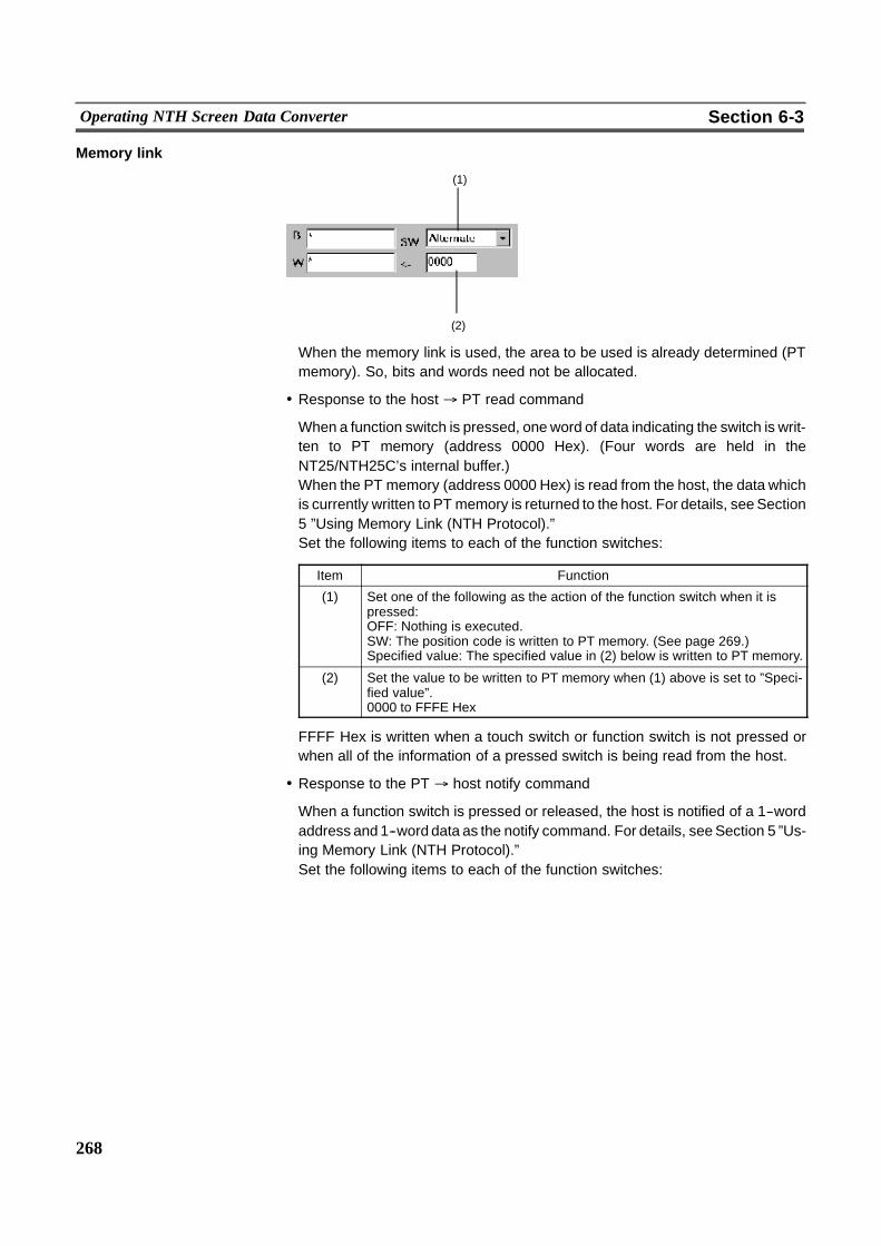
268
Operating NTH Screen Data Converter Section 6-3
Memory link
(2)
(1)
When the memory link is used, the area to be used is already determined (PTmemory). So, bits and words need not be allocated.
! Response to the host % PT read command
When a function switch is pressed, one word of data indicating the switch is writ-ten to PT memory (address 0000 Hex). (Four words are held in theNT25/NTH25C’s internal buffer.)When the PT memory (address 0000 Hex) is read from the host, the data whichis currently written to PT memory is returned to the host. For details, seeSection5 ”Using Memory Link (NTH Protocol).”Set the following items to each of the function switches:
Item Function
(1) Set one of the following as the action of the function switch when it ispressed:OFF: Nothing is executed.SW: The position code is written to PT memory. (See page 269.)Specified value: The specified value in (2) below is written to PT memory.
(2) Set the value to be written to PT memory when (1) above is set to ”Speci-fied value”.0000 to FFFE Hex
FFFF Hex is written when a touch switch or function switch is not pressed orwhen all of the information of a pressed switch is being read from the host.
! Response to the PT % host notify command
When a function switch is pressed or released, the host is notified of a 1--wordaddress and 1--word data as the notify command. For details, seeSection 5 ”Us-ing Memory Link (NTH Protocol).”Set the following items to each of the function switches:
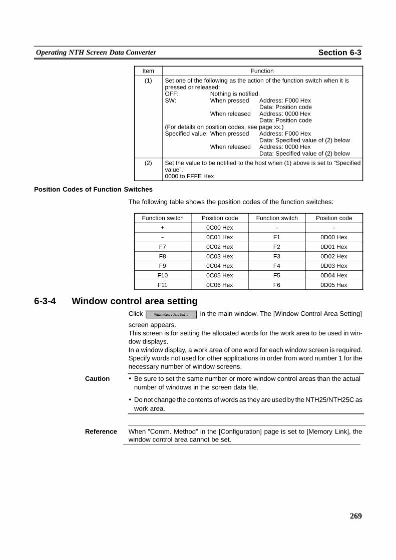
269
Operating NTH Screen Data Converter Section 6-3
Item Function
(1) Set one of the following as the action of the function switch when it ispressed or released:OFF: Nothing is notified.SW: When pressed Address: F000 Hex
Data: Position codeWhen released Address: 0000 Hex
Data: Position code(For details on position codes, see page xx.)Specified value: When pressed Address: F000 Hex
Data: Specified value of (2) belowWhen released Address: 0000 Hex
Data: Specified value of (2) below
(2) Set the value to be notified to the host when (1) above is set to ”Specifiedvalue”.0000 to FFFE Hex
Position Codes of Function Switches
The following table shows the position codes of the function switches:
Function switch Position code Function switch Position code
+ 0C00 Hex -- --
-- 0C01 Hex F1 0D00 Hex
F7 0C02 Hex F2 0D01 Hex
F8 0C03 Hex F3 0D02 Hex
F9 0C04 Hex F4 0D03 Hex
F10 0C05 Hex F5 0D04 Hex
F11 0C06 Hex F6 0D05 Hex
6-3-4 Window control area settingClick in the main window. The [Window Control Area Setting]
screen appears.This screen is for setting the allocated words for the work area to be used in win-dow displays.In a window display, a work area of one word for each window screen is required.Specify words not used for other applications in order from word number 1 for thenecessary number of window screens.
Caution ! Be sure to set the same number or more window control areas than the actualnumber of windows in the screen data file.
! Donot change the contents of words as they areused by theNTH25/NTH25C aswork area.
Reference When ”Comm. Method” in the [Configuration] page is set to [Memory Link], thewindow control area cannot be set.
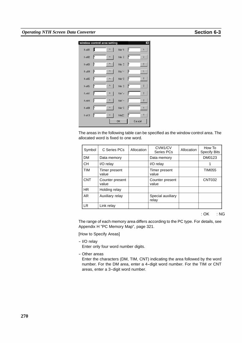
270
Operating NTH Screen Data Converter Section 6-3
window control area setting
The areas in the following table can be specified as the window control area. Theallocated word is fixed to one word.
Symbol C Series PCs Allocation CVM1/CVSeries PCs Allocation How To
Specify Bits
DM Data memory � Data memory � DM0123
CH I/O relay � I/O relay � 1
TIM Timer presentvalue
� Timer presentvalue
� TIM055
CNT Counter presentvalue
� Counter presentvalue
� CNT032
HR Holding relay � � � �AR Auxiliary relay � Special auxiliary
relay� �
LR Link relay � � � �
� : OK � : NG
The range of each memory area differs according to the PC type. For details, seeAppendix H ”PC Memory Map”, page 321.
[How to Specify Areas]
-- I/O relayEnter only four word number digits.
-- Other areasEnter the characters (DM, TIM, CNT) indicating the area followed by the wordnumber. For the DM area, enter a 4--digit word number. For the TIM or CNTareas, enter a 3--digit word number.
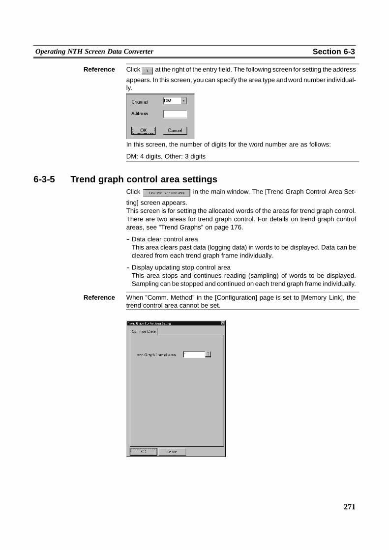
271
Operating NTH Screen Data Converter Section 6-3
Reference Click at the right of the entry field. The following screen for setting the address
appears. In this screen, you can specify the area type andword number individual-ly.
In this screen, the number of digits for the word number are as follows:
DM: 4 digits, Other: 3 digits
6-3-5 Trend graph control area settingsClick in the main window. The [Trend Graph Control Area Set-
ting] screen appears.This screen is for setting the allocated words of the areas for trend graph control.There are two areas for trend graph control. For details on trend graph controlareas, see ”Trend Graphs” on page 176.
-- Data clear control areaThis area clears past data (logging data) in words to be displayed. Data can becleared from each trend graph frame individually.
-- Display updating stop control areaThis area stops and continues reading (sampling) of words to be displayed.Sampling can be stopped and continued on each trend graph frame individually.
Reference When ”Comm. Method” in the [Configuration] page is set to [Memory Link], thetrend control area cannot be set.
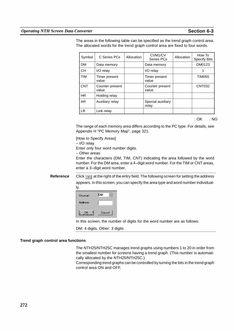
272
Operating NTH Screen Data Converter Section 6-3
The areas in the following table can be specified as the trend graph control area.The allocated words for the trend graph control area are fixed to four words.
Symbol C Series PCs Allocation CVM1/CVSeries PCs Allocation How To
Specify Bits
DM Data memory � Data memory � DM0123
CH I/O relay � I/O relay � 1
TIM Timer presentvalue
� Timer presentvalue
� TIM055
CNT Counter presentvalue
� Counter presentvalue
� CNT032
HR Holding relay � � � �AR Auxiliary relay � Special auxiliary
relay� �
LR Link relay � � � �
� : OK � : NG
The range of each memory area differs according to the PC type. For details, seeAppendix H ”PC Memory Map”, page 321.
[How to Specify Areas]-- I/O relayEnter only four word number digits.-- Other areasEnter the characters (DM, TIM, CNT) indicating the area followed by the wordnumber. For the DM area, enter a 4--digit word number. For the TIM or CNT areas,enter a 3--digit word number.
Reference Click at the right of the entry field. The following screen for setting the address
appears. In this screen, you can specify the area type andword number individual-ly.
In this screen, the number of digits for the word number are as follows:
DM: 4 digits, Other: 3 digits
Trend graph control area functions
The NTH25/NTH25C manages trend graphs using numbers 1 to 20 in order fromthe smallest number for screens having a trend graph. (This number is automati-cally allocated by the NTH25/NTH25C.)Corresponding trend graphs can be controlled by turning the bits in the trend graphcontrol area ON and OFF.
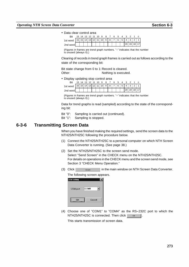
273
Operating NTH Screen Data Converter Section 6-3
! Data clear control area
16 15 14 13 12 11 10 9 8 7 6 5 4 3 2 11st word
15 14 13 12 11 10 9 8 7 6 5 4 3 2 1 0Bit
� � � � � � � � � � � � 20 19 18 172nd word
(Figures in frames are trend graph numbers. ”--” indicates that the numberis unused (always 0).)
Clearing of records in trend graph frames is carried out as follows according to thestate of the corresponding bit:
Bit state change from 0 to 1:Record is cleared.Other: Nothing is executed.
! Display updating stop control area
16 15 14 13 12 11 10 9 8 7 6 5 4 3 2 11st word
15 14 13 12 11 10 9 8 7 6 5 4 3 2 1 0Bit
� � � � � � � � � � � � 20 19 18 172nd word
(Figures in frames are trend graph numbers. ”--” indicates that the numberis unused (always 0).)
Data for trend graphs is read (sampled) according to the state of the correspond-ing bit:
Bit ”0”: Sampling is carried out (continued).Bit ”1”: Sampling is stopped.
6-3-6 Transmitting Screen DataWhen you have finishedmaking the required settings, send the screen data to theNTH25/NTH25C following the procedure below.
(1) Connect the NTH25/NTH25C to a personal computer on which NTH ScreenData Converter is running. (See page 38.)
(2) Set the NTH25/NTH25C to the screen send mode.Select ”Send Screen” in the CHECK menu on the NTH25/NTH25C.For details on operations in theCHECKmenu and the screen sendmode, seeSection 3 ”CHECK Menu Operation.”
(3) Click in the main window on NTH Screen Data Converter.
The following screen appears.
(4) Choose one of ”COM1” to ”COM4” as the RS--232C port to which theNTH25/NTH25C is connected. Then click .
This starts transmission of screen data.
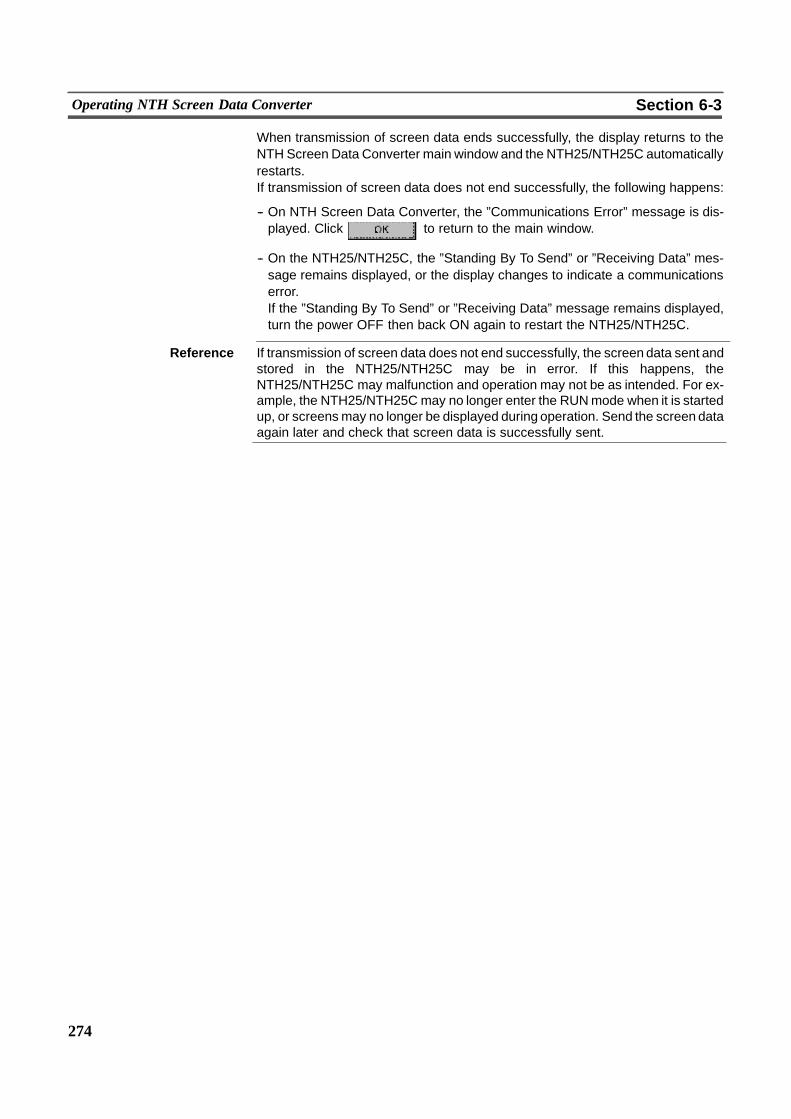
274
Operating NTH Screen Data Converter Section 6-3
When transmission of screen data ends successfully, the display returns to theNTH Screen Data Converter main window and the NTH25/NTH25C automaticallyrestarts.If transmission of screen data does not end successfully, the following happens:
-- On NTH Screen Data Converter, the ”Communications Error” message is dis-played. Click to return to the main window.
-- On the NTH25/NTH25C, the ”Standing By To Send” or ”Receiving Data” mes-sage remains displayed, or the display changes to indicate a communicationserror.If the ”Standing By To Send” or ”Receiving Data” message remains displayed,turn the power OFF then back ON again to restart the NTH25/NTH25C.
Reference If transmission of screen data does not end successfully, the screen data sent andstored in the NTH25/NTH25C may be in error. If this happens, theNTH25/NTH25C may malfunction and operation may not be as intended. For ex-ample, the NTH25/NTH25C may no longer enter the RUNmode when it is startedup, or screensmay no longer be displayed during operation. Send the screen dataagain later and check that screen data is successfully sent.
275
SECTION 7Troubleshooting and Maintenance
This section describes the action to take when an error occurs during NTH25/NTH25C operation, and how to carry out main-tenance and inspection to prevent errors from occurring.
7-1 Troubleshooting 276. . . . . . . . . . . . . . . . . . . . . . . . . . . . . . . . . . . . . . . . . . . . . . . . . . . . . . . . . . . . . .7-2 Maintenance of the NTH25/NTH25C 281. . . . . . . . . . . . . . . . . . . . . . . . . . . . . . . . . . . . . . . . . . . . .7-3 Inspection and Cleaning 282. . . . . . . . . . . . . . . . . . . . . . . . . . . . . . . . . . . . . . . . . . . . . . . . . . . . . . .
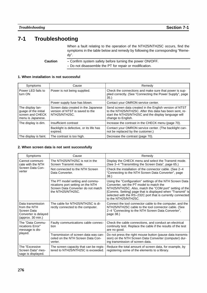
276
Troubleshooting Section 7-1
7-1 TroubleshootingWhen a fault relating to the operation of the NTH25/NTH25C occurs, find thesymptoms in the table below and remedy by following the corresponding ”Reme-dy”.
Caution -- Confirm system safety before turning the power ON/OFF.-- Do not disassemble the PT for repair or modification.
1. When installation is not successful
Symptoms Cause Remedy
Power LED fails toturn ON
Power is not being supplied. Check the connections and make sure that power is sup-plied correctly. (See ”Connecting the Power Supply”, page35.)
Power supply fuse has blown. Contact your OMRON service center.
The display lan-guage of the initialscreen and CHECKmenu is Japanese.
Screen data created in the Japaneseversion of NTST is saved to theNTH25/NTH25C.
Send screen data created in the English version of NTSTto the NTH25/NTH25C. After this data has been sent, re-start the NTH25/NTH25C and the display language willchange to English.
The display is dim. Insufficient contrast Increase the contrast in the CHECK menu (page 70).p y
Backlight is defective, or its life hasexpired.
Contact your OMRON service center. (The backlight can-not be replaced by the customer.)
The display is faint. The contrast is too high. Decrease the contrast (page 70).
2. When screen data is not sent successfully
Symptoms Cause Remedy
Cannot communi-cate with the NTH
The NTH25/NTH25C is not in theScreen Transmit mode.
Display the CHECK menu and select the Transmit mode.(See 3--4 ”Transmitting the Screen Data”, page 65.)cate with the NTH
Screen Data Con-verter
Not connected to the NTH ScreenData Converter.
Check the installation of the connector cable. (See 2--4”Connecting to the NTH Screen Data Converter”, page38.)
The PT model setting and commu-nications port setting on the NTHScreen Data Converter do not matchthe NTH25/NTH25C.
Using the ”Configuration” settings of the NTH Screen DataConverter, set the PT model to match theNTH25/NTH25C. Also, match the ”COM port” setting of the[Comms. Setting] page that is displayed when ”Transmit” isselected with the RS--232C port that is currently connectedto the NTH25/NTH25C.
Data transmissionfrom the NTHScreen DataConverter is delayed(approx. 30 min.)
The cable for NTH25/NTH25C is di-rectly connected to the computer.
Connect the tool connector cable to the computer, and theNTH25/NTH25C cable to the tool connector cable. (See2--4 ”Connecting to the NTH Screen Data Converter”,page 38.)
The ”Data Commu-nications Error”message is dis-l d
Faulty communications cable connec-tion
Check the cable connections, and conduct an electricalcontinuity test. Replace the cable if the results of the testare no good.g
played. Transmission of screen data was can-celed on the NTH Screen Data Con-verter.
Do not press the right mouse button (pause data transmis-sion) on the NTH Screen Data Converter (computer) dur-ing transmission of screen data.
The ”ExcessiveScreen Data” mes-sage is displayed.
The screen capacity that can be regis-tered to NTH25/NTH25C is exceeded.
Reduce the total amount of screen data, for example, byregistering some of the elements to a library.
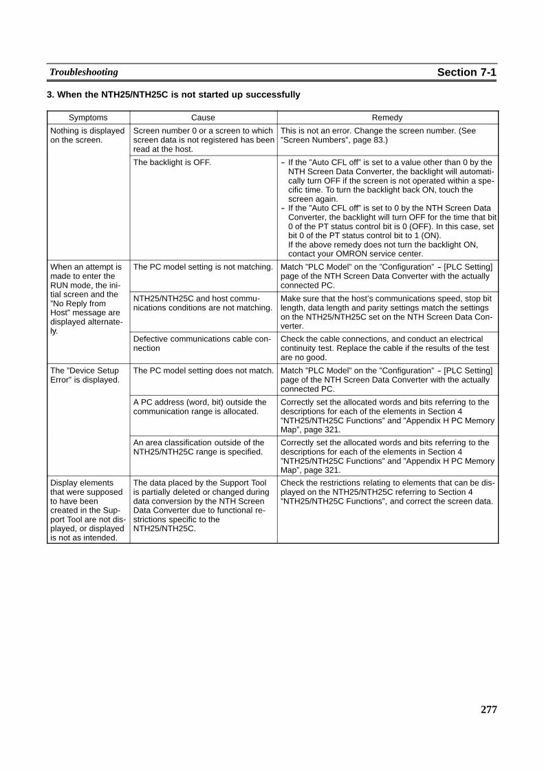
277
Troubleshooting Section 7-1
3. When the NTH25/NTH25C is not started up successfully
Symptoms Cause Remedy
Nothing is displayedon the screen.
Screen number 0 or a screen to whichscreen data is not registered has beenread at the host.
This is not an error. Change the screen number. (See”Screen Numbers”, page 83.)
The backlight is OFF. -- If the ”Auto CFL off” is set to a value other than 0 by theNTH Screen Data Converter, the backlight will automati-cally turn OFF if the screen is not operated within a spe-cific time. To turn the backlight back ON, touch thescreen again.
-- If the ”Auto CFL off” is set to 0 by the NTH Screen DataConverter, the backlight will turn OFF for the time that bit0 of the PT status control bit is 0 (OFF). In this case, setbit 0 of the PT status control bit to 1 (ON).If the above remedy does not turn the backlight ON,contact your OMRON service center.
When an attempt ismade to enter theRUN mode, the ini-i l d h
The PC model setting is not matching. Match ”PLC Model” on the ”Configuration” -- [PLC Setting]page of the NTH Screen Data Converter with the actuallyconnected PC.,
tial screen and the”No Reply fromHost” message aredisplayed alternate-ly
NTH25/NTH25C and host commu-nications conditions are not matching.
Make sure that the host’s communications speed, stop bitlength, data length and parity settings match the settingson the NTH25/NTH25C set on the NTH Screen Data Con-verter.
ly.Defective communications cable con-nection
Check the cable connections, and conduct an electricalcontinuity test. Replace the cable if the results of the testare no good.
The ”Device SetupError” is displayed.
The PC model setting does not match. Match ”PLC Model” on the ”Configuration” -- [PLC Setting]page of the NTH Screen Data Converter with the actuallyconnected PC.
A PC address (word, bit) outside thecommunication range is allocated.
Correctly set the allocated words and bits referring to thedescriptions for each of the elements in Section 4”NTH25/NTH25C Functions” and ”Appendix H PC MemoryMap”, page 321.
An area classification outside of theNTH25/NTH25C range is specified.
Correctly set the allocated words and bits referring to thedescriptions for each of the elements in Section 4”NTH25/NTH25C Functions” and ”Appendix H PC MemoryMap”, page 321.
Display elementsthat were supposedto have beencreated in the Sup-port Tool are not dis-played, or displayedis not as intended.
The data placed by the Support Toolis partially deleted or changed duringdata conversion by the NTH ScreenData Converter due to functional re-strictions specific to theNTH25/NTH25C.
Check the restrictions relating to elements that can be dis-played on the NTH25/NTH25C referring to Section 4”NTH25/NTH25C Functions”, and correct the screen data.
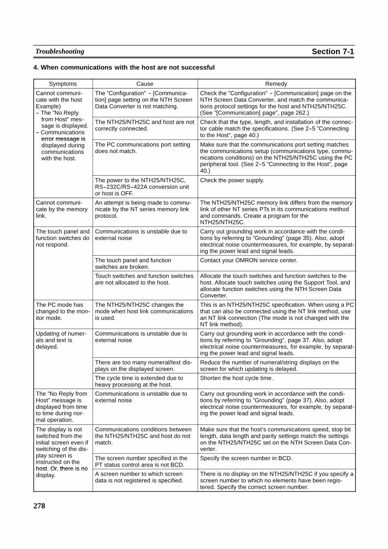
278
Troubleshooting Section 7-1
4. When communications with the host are not successful
Symptoms Cause Remedy
Cannot communi-cate with the hostExample)-- The ”No Reply
The ”Configuration” -- [Communica-tion] page setting on the NTH ScreenData Converter is not matching.
Check the ”Configuration” -- [Communication] page on theNTH Screen Data Converter, and match the communica-tions protocol settings for the host and NTH25/NTH25C.(See ”[Communication] page”, page 262.)p y
from Host” mes-sage is displayed.
-- Communicationserror message is
The NTH25/NTH25C and host are notcorrectly connected.
Check that the type, length, and installation of the connec-tor cable match the specifications. (See 2--5 ”Connectingto the Host”, page 40.)
error message isdisplayed duringcommunicationswith the host.
The PC communications port settingdoes not match.
Make sure that the communications port setting matchesthe communications setup (communications type, commu-nications conditions) on the NTH25/NTH25C using the PCperipheral tool. (See 2--5 ”Connecting to the Host”, page40.)
The power to the NTH25/NTH25C,RS--232C/RS--422A conversion unitor host is OFF.
Check the power supply.
Cannot communi-cate by the memorylink.
An attempt is being made to commu-nicate by the NT series memory linkprotocol.
The NTH25/NTH25C memory link differs from the memorylink of other NT series PTs in its communications methodand commands. Create a program for theNTH25/NTH25C.
The touch panel andfunction switches donot respond.
Communications is unstable due toexternal noise
Carry out grounding work in accordance with the condi-tions by referring to ”Grounding” (page 35). Also, adoptelectrical noise countermeasures, for example, by separat-ing the power lead and signal leads.
The touch panel and functionswitches are broken.
Contact your OMRON service center.
Touch switches and function switchesare not allocated to the host.
Allocate the touch switches and function switches to thehost. Allocate touch switches using the Support Tool, andallocate function switches using the NTH Screen DataConverter.
The PC mode haschanged to the mon-itor mode.
The NTH25/NTH25C changes themode when host link communicationsis used.
This is an NTH25/NTH25C specification. When using a PCthat can also be connected using the NT link method, usean NT link connection (The mode is not changed with theNT link method).
Updating of numer-als and text isdelayed.
Communications is unstable due toexternal noise
Carry out grounding work in accordance with the condi-tions by referring to ”Grounding”, page 37. Also, adoptelectrical noise countermeasures, for example, by separat-ing the power lead and signal leads.
There are too many numeral/text dis-plays on the displayed screen.
Reduce the number of numeral/string displays on thescreen for which updating is delayed.
The cycle time is extended due toheavy processing at the host.
Shorten the host cycle time.
The ”No Reply fromHost” message isdisplayed from timeto time during nor-mal operation.
Communications is unstable due toexternal noise
Carry out grounding work in accordance with the condi-tions by referring to ”Grounding” (page 37). Also, adoptelectrical noise countermeasures, for example, by separat-ing the power lead and signal leads.
The display is notswitched from theinitial screen even ifswitching of the dis-
Communications conditions betweenthe NTH25/NTH25C and host do notmatch.
Make sure that the host’s communications speed, stop bitlength, data length and parity settings match the settingson the NTH25/NTH25C set on the NTH Screen Data Con-verter.g
play screen isinstructed on thehost Or there is no
The screen number specified in thePT status control area is not BCD.
Specify the screen number in BCD.
host. Or, there is nodisplay. A screen number to which screen
data is not registered is specified.There is no display on the NTH25/NTH25C if you specify ascreen number to which no elements have been regis-tered. Specify the correct screen number.
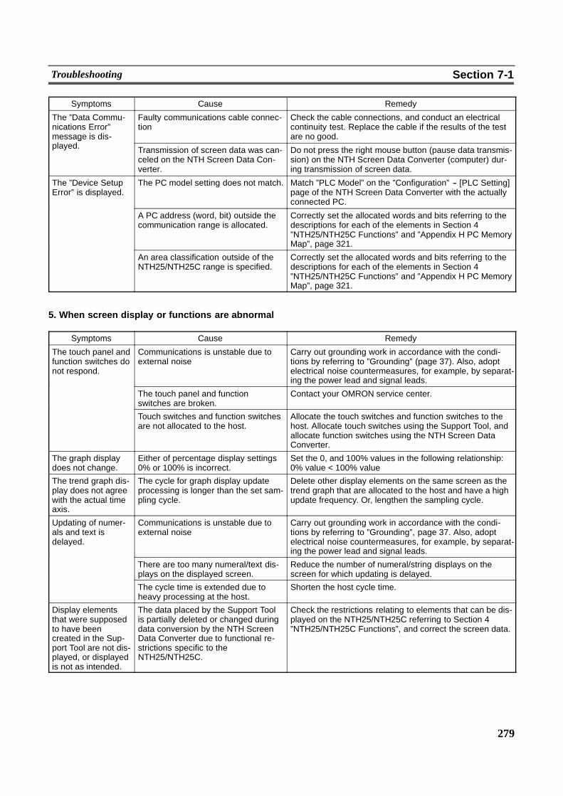
279
Troubleshooting Section 7-1
Symptoms Cause Remedy
The ”Data Commu-nications Error”message is dis-l d
Faulty communications cable connec-tion
Check the cable connections, and conduct an electricalcontinuity test. Replace the cable if the results of the testare no good.g
played. Transmission of screen data was can-celed on the NTH Screen Data Con-verter.
Do not press the right mouse button (pause data transmis-sion) on the NTH Screen Data Converter (computer) dur-ing transmission of screen data.
The ”Device SetupError” is displayed.
The PC model setting does not match. Match ”PLC Model” on the ”Configuration” -- [PLC Setting]page of the NTH Screen Data Converter with the actuallyconnected PC.
A PC address (word, bit) outside thecommunication range is allocated.
Correctly set the allocated words and bits referring to thedescriptions for each of the elements in Section 4”NTH25/NTH25C Functions” and ”Appendix H PC MemoryMap”, page 321.
An area classification outside of theNTH25/NTH25C range is specified.
Correctly set the allocated words and bits referring to thedescriptions for each of the elements in Section 4”NTH25/NTH25C Functions” and ”Appendix H PC MemoryMap”, page 321.
5. When screen display or functions are abnormal
Symptoms Cause Remedy
The touch panel andfunction switches donot respond.
Communications is unstable due toexternal noise
Carry out grounding work in accordance with the condi-tions by referring to ”Grounding” (page 37). Also, adoptelectrical noise countermeasures, for example, by separat-ing the power lead and signal leads.
The touch panel and functionswitches are broken.
Contact your OMRON service center.
Touch switches and function switchesare not allocated to the host.
Allocate the touch switches and function switches to thehost. Allocate touch switches using the Support Tool, andallocate function switches using the NTH Screen DataConverter.
The graph displaydoes not change.
Either of percentage display settings0% or 100% is incorrect.
Set the 0, and 100% values in the following relationship:0% value < 100% value
The trend graph dis-play does not agreewith the actual timeaxis.
The cycle for graph display updateprocessing is longer than the set sam-pling cycle.
Delete other display elements on the same screen as thetrend graph that are allocated to the host and have a highupdate frequency. Or, lengthen the sampling cycle.
Updating of numer-als and text isdelayed.
Communications is unstable due toexternal noise
Carry out grounding work in accordance with the condi-tions by referring to ”Grounding”, page 37. Also, adoptelectrical noise countermeasures, for example, by separat-ing the power lead and signal leads.
There are too many numeral/text dis-plays on the displayed screen.
Reduce the number of numeral/string displays on thescreen for which updating is delayed.
The cycle time is extended due toheavy processing at the host.
Shorten the host cycle time.
Display elementsthat were supposedto have beencreated in the Sup-port Tool are not dis-played, or displayedis not as intended.
The data placed by the Support Toolis partially deleted or changed duringdata conversion by the NTH ScreenData Converter due to functional re-strictions specific to theNTH25/NTH25C.
Check the restrictions relating to elements that can be dis-played on the NTH25/NTH25C referring to Section 4”NTH25/NTH25C Functions”, and correct the screen data.
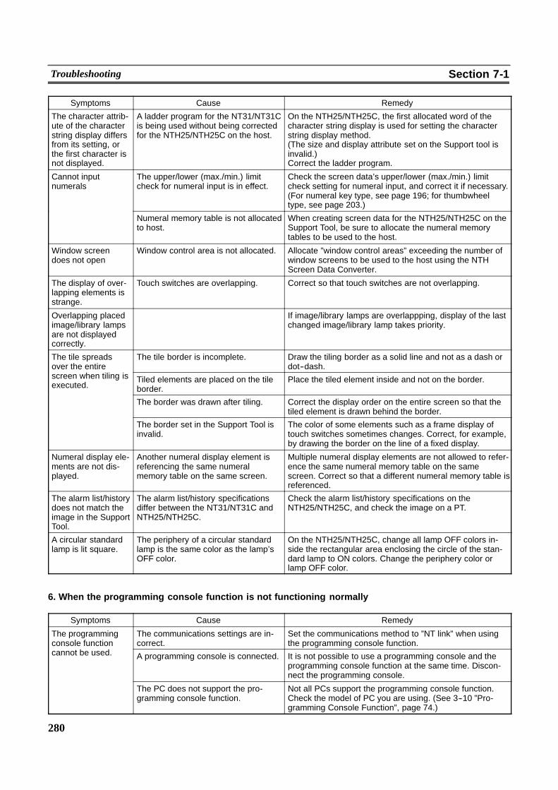
280
Troubleshooting Section 7-1
Symptoms Cause Remedy
The character attrib-ute of the characterstring display differsfrom its setting, orthe first character isnot displayed.
A ladder program for the NT31/NT31Cis being used without being correctedfor the NTH25/NTH25C on the host.
On the NTH25/NTH25C, the first allocated word of thecharacter string display is used for setting the characterstring display method.(The size and display attribute set on the Support tool isinvalid.)Correct the ladder program.
Cannot inputnumerals
The upper/lower (max./min.) limitcheck for numeral input is in effect.
Check the screen data’s upper/lower (max./min.) limitcheck setting for numeral input, and correct it if necessary.(For numeral key type, see page 196; for thumbwheeltype, see page 203.)
Numeral memory table is not allocatedto host.
When creating screen data for the NTH25/NTH25C on theSupport Tool, be sure to allocate the numeral memorytables to be used to the host.
Window screendoes not open
Window control area is not allocated. Allocate ”window control areas” exceeding the number ofwindow screens to be used to the host using the NTHScreen Data Converter.
The display of over-lapping elements isstrange.
Touch switches are overlapping. Correct so that touch switches are not overlapping.
Overlapping placedimage/library lampsare not displayedcorrectly.
� If image/library lamps are overlappping, display of the lastchanged image/library lamp takes priority.
The tile spreadsover the entire
The tile border is incomplete. Draw the tiling border as a solid line and not as a dash ordot--dash.over the entire
screen when tiling isexecuted.
Tiled elements are placed on the tileborder.
Place the tiled element inside and not on the border.
The border was drawn after tiling. Correct the display order on the entire screen so that thetiled element is drawn behind the border.
The border set in the Support Tool isinvalid.
The color of some elements such as a frame display oftouch switches sometimes changes. Correct, for example,by drawing the border on the line of a fixed display.
Numeral display ele-ments are not dis-played.
Another numeral display element isreferencing the same numeralmemory table on the same screen.
Multiple numeral display elements are not allowed to refer-ence the same numeral memory table on the samescreen. Correct so that a different numeral memory table isreferenced.
The alarm list/historydoes not match theimage in the SupportTool.
The alarm list/history specificationsdiffer between the NT31/NT31C andNTH25/NTH25C.
Check the alarm list/history specifications on theNTH25/NTH25C, and check the image on a PT.
A circular standardlamp is lit square.
The periphery of a circular standardlamp is the same color as the lamp’sOFF color.
On the NTH25/NTH25C, change all lamp OFF colors in-side the rectangular area enclosing the circle of the stan-dard lamp to ON colors. Change the periphery color orlamp OFF color.
6. When the programming console function is not functioning normally
Symptoms Cause Remedy
The programmingconsole function
The communications settings are in-correct.
Set the communications method to ”NT link” when usingthe programming console function.console function
cannot be used. A programming console is connected. It is not possible to use a programming console and theprogramming console function at the same time. Discon-nect the programming console.
The PC does not support the pro-gramming console function.
Not all PCs support the programming console function.Check the model of PC you are using. (See 3--10 ”Pro-gramming Console Function”, page 74.)
281
Maintenance of the NTH25/NTH25C Section 7-2
7-2 Maintenance of the NTH25/NTH25CCarry out maintenance work in order to ensure that the NTH25/NTH25C is alwaysin optimum working order.
Do not attempt to take the NTH25/NTH25C apart and do nottouch any internal parts while the power is being supplied.Doing so might result in electrical shock.
Caution Continual display of the same pattern for a long time (roughly 24 hours) will resultin a residual image forming on the screen. Periodically switch the screen displayto prevent residual images from forming.
Spare PT
We recommend preparing a spareNTH25/NTH25C tominimize system downtimein the event of an NTH25/NTH25C failure or if the screen display becomes difficultto read due to deterioration of the display unit.
Backlight
When the backlight in the display dims and it is difficult to view the screen, contactyour OMRON service center and wewill replace the backlight. (The backlight can-not be replaced by the customer.)
! Guide to backlight replacement
Under normal operating conditions it can be assumed that the backlight will needto be replaced after about 10,000 hours. However, the life of the backlight doesvaries, particularly, in accordance with the temperature in the environment inwhich it is used. (For example, use in low temperatures reduces the life of thebacklight.) It should be replaced when the display dims and the screen is difficult toview.
WARNING
282
Inspection and Cleaning Section 7-3
7-3 Inspection and CleaningClean and inspect the NTH25/NTH25C regularly to ensure that it is always in opti-mum working order.
Cleaning Method
When the display becomes dirty, the screen becomes difficult to view. Clean thescreen from time to time as follows.
- In daily cleaning, wipe the display with a soft dry cloth. If it is particularly dirty,attempting to remove it by wiping with a dry cloth may damage the front sheet ofthe unit. In this case, wipe with a damp cloth beforehand.
- If dirt cannot be removed with a dry cloth, wipe the display with a firmly wrungcloth moistened with diluted neutral detergent (2%).
- If rubber or vinyl products such as tape, are left stuck to the display for long peri-ods they may cause dirt stains. If such items are stuck to the display, removethem during cleaning.
Caution Never use volatile solvents such as benzene or paint thinner, or chemical dusters.
Inspection Method
In normal operating environments, inspect the NTH25/NTH25C at intervals of be-tween 6 months and a year. In environments that are extremely hot and humid, orvery dusty environments, shorten the inspection interval.
! Items required for inspection
Prepare the following items before starting the inspection:
-- Screwdrivers (Philips, flat head)-- Tester (or digital voltmeter)-- Industrial alcohol-- 100% cotton cloth-- Hygrometer (required in some cases)-- Thermometer (required in some cases)-- Synchroscope (required in some cases)

283
Inspection and Cleaning Section 7-3
! Points inspected
Inspect the following points to determine whether or not they are within the stan-dard. If they are not, either improve the surrounding environment so that the val-ues fall within the standard, or adjust the NTH25/NTH25C, for example by re--tightening screws.
Point Inspected Inspection Details Standard Inspection Instrument
Power supplyvoltage
Fluctuation in power supply ter-minal voltage
Permissible voltage fluctuation range(24 VDC --15% to +10%)
Tester
Ambient environ-mental conditions
Ambient temperature (tempera-ture inside operation panel)
0 to 50� Thermometermental conditions
Ambient humidity (humidity in theoperation panel)
35% to 85% RH Hygrometer
Dust Dust must not be accumulating. Visual inspection
Mounting site Connection of connector cables Connectors must be fully inserted andlocked, and not be loose.
Philips screwdriver
Screws must not be loose. To be no looseness Philips screwdriver
State of external connectorcables
Faults such as incipient disconnection Visual inspection
Components withlimited lives
Brightness of the backlight Must be sufficiently bright.Backlight life (room temperature and hu-midity):Brightness is halved after about 10,000hours in use.
Visual inspection
Caution -- Do not disassemble for repairs or modification.
-- Disposal of the NTH25/NTH25C (including the backlight) may be regulated bynational or local authorities. Dispose the NTH25/NTH25C (including the back-light) in accordance with the laws and regulations of the relevant country andlocal authority.
Reference Request When Replacing the NTH25/NTH25CWhen replacing the NTH25/NTH25C after discovering a fault during inspections,note the following points:
-- Be sure to switch the power OFF before starting replacement.
-- After replacement, check that the new NTH25/NTH25C is free of errors.
-- If a faulty NTH25/NTH25C is returned for repairs, write as detailed a descriptionof the fault as possible and send this description together with theNTH25/NTH25C to the OMRON address indicated on the back cover of thisbook.
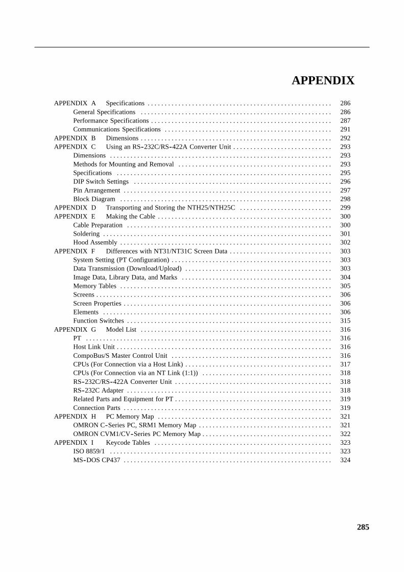
285
APPENDIX A Specifications 286. . . . . . . . . . . . . . . . . . . . . . . . . . . . . . . . . . . . . . . . . . . . . . . . . . . . . .General Specifications 286. . . . . . . . . . . . . . . . . . . . . . . . . . . . . . . . . . . . . . . . . . . . . . . . . . . . . . . .Performance Specifications 287. . . . . . . . . . . . . . . . . . . . . . . . . . . . . . . . . . . . . . . . . . . . . . . . . . . . .Communications Specifications 291. . . . . . . . . . . . . . . . . . . . . . . . . . . . . . . . . . . . . . . . . . . . . . . . .
APPENDIX B Dimensions 292. . . . . . . . . . . . . . . . . . . . . . . . . . . . . . . . . . . . . . . . . . . . . . . . . . . . . . . .APPENDIX C Using an RS--232C/RS--422A Converter Unit 293. . . . . . . . . . . . . . . . . . . . . . . . . . . . .
Dimensions 293. . . . . . . . . . . . . . . . . . . . . . . . . . . . . . . . . . . . . . . . . . . . . . . . . . . . . . . . . . . . . . . . .Methods for Mounting and Removal 293. . . . . . . . . . . . . . . . . . . . . . . . . . . . . . . . . . . . . . . . . . . . .Specifications 295. . . . . . . . . . . . . . . . . . . . . . . . . . . . . . . . . . . . . . . . . . . . . . . . . . . . . . . . . . . . . . .DIP Switch Settings 296. . . . . . . . . . . . . . . . . . . . . . . . . . . . . . . . . . . . . . . . . . . . . . . . . . . . . . . . . .Pin Arrangement 297. . . . . . . . . . . . . . . . . . . . . . . . . . . . . . . . . . . . . . . . . . . . . . . . . . . . . . . . . . . . .Block Diagram 298. . . . . . . . . . . . . . . . . . . . . . . . . . . . . . . . . . . . . . . . . . . . . . . . . . . . . . . . . . . . . .
APPENDIX D Transporting and Storing the NTH25/NTH25C 299. . . . . . . . . . . . . . . . . . . . . . . . . . .APPENDIX E Making the Cable 300. . . . . . . . . . . . . . . . . . . . . . . . . . . . . . . . . . . . . . . . . . . . . . . . . . .
Cable Preparation 300. . . . . . . . . . . . . . . . . . . . . . . . . . . . . . . . . . . . . . . . . . . . . . . . . . . . . . . . . . . .Soldering 301. . . . . . . . . . . . . . . . . . . . . . . . . . . . . . . . . . . . . . . . . . . . . . . . . . . . . . . . . . . . . . . . . . .Hood Assembly 302. . . . . . . . . . . . . . . . . . . . . . . . . . . . . . . . . . . . . . . . . . . . . . . . . . . . . . . . . . . . . .
APPENDIX F Differences with NT31/NT31C Screen Data 303. . . . . . . . . . . . . . . . . . . . . . . . . . . . . .System Setting (PT Configuration) 303. . . . . . . . . . . . . . . . . . . . . . . . . . . . . . . . . . . . . . . . . . . . . . .Data Transmission (Download/Upload) 303. . . . . . . . . . . . . . . . . . . . . . . . . . . . . . . . . . . . . . . . . . .Image Data, Library Data, and Marks 304. . . . . . . . . . . . . . . . . . . . . . . . . . . . . . . . . . . . . . . . . . . .Memory Tables 305. . . . . . . . . . . . . . . . . . . . . . . . . . . . . . . . . . . . . . . . . . . . . . . . . . . . . . . . . . . . . .Screens 306. . . . . . . . . . . . . . . . . . . . . . . . . . . . . . . . . . . . . . . . . . . . . . . . . . . . . . . . . . . . . . . . . . . . .Screen Properties 306. . . . . . . . . . . . . . . . . . . . . . . . . . . . . . . . . . . . . . . . . . . . . . . . . . . . . . . . . . . . .Elements 306. . . . . . . . . . . . . . . . . . . . . . . . . . . . . . . . . . . . . . . . . . . . . . . . . . . . . . . . . . . . . . . . . . .Function Switches 315. . . . . . . . . . . . . . . . . . . . . . . . . . . . . . . . . . . . . . . . . . . . . . . . . . . . . . . . . . . .
APPENDIX G Model List 316. . . . . . . . . . . . . . . . . . . . . . . . . . . . . . . . . . . . . . . . . . . . . . . . . . . . . . . .PT 316. . . . . . . . . . . . . . . . . . . . . . . . . . . . . . . . . . . . . . . . . . . . . . . . . . . . . . . . . . . . . . . . . . . . . . . .Host Link Unit 316. . . . . . . . . . . . . . . . . . . . . . . . . . . . . . . . . . . . . . . . . . . . . . . . . . . . . . . . . . . . . . .CompoBus/S Master Control Unit 316. . . . . . . . . . . . . . . . . . . . . . . . . . . . . . . . . . . . . . . . . . . . . . .CPUs (For Connection via a Host Link) 317. . . . . . . . . . . . . . . . . . . . . . . . . . . . . . . . . . . . . . . . . . .CPUs (For Connection via an NT Link (1:1)) 318. . . . . . . . . . . . . . . . . . . . . . . . . . . . . . . . . . . . . .RS--232C/RS--422A Converter Unit 318. . . . . . . . . . . . . . . . . . . . . . . . . . . . . . . . . . . . . . . . . . . . . .RS--232C Adapter 318. . . . . . . . . . . . . . . . . . . . . . . . . . . . . . . . . . . . . . . . . . . . . . . . . . . . . . . . . . . .Related Parts and Equipment for PT 319. . . . . . . . . . . . . . . . . . . . . . . . . . . . . . . . . . . . . . . . . . . . . .Connection Parts 319. . . . . . . . . . . . . . . . . . . . . . . . . . . . . . . . . . . . . . . . . . . . . . . . . . . . . . . . . . . . .
APPENDIX H PC Memory Map 321. . . . . . . . . . . . . . . . . . . . . . . . . . . . . . . . . . . . . . . . . . . . . . . . . . .OMRON C--Series PC, SRM1 Memory Map 321. . . . . . . . . . . . . . . . . . . . . . . . . . . . . . . . . . . . . . .OMRON CVM1/CV--Series PC Memory Map 322. . . . . . . . . . . . . . . . . . . . . . . . . . . . . . . . . . . . . .
APPENDIX I Keycode Tables 323. . . . . . . . . . . . . . . . . . . . . . . . . . . . . . . . . . . . . . . . . . . . . . . . . . . .ISO 8859/1 323. . . . . . . . . . . . . . . . . . . . . . . . . . . . . . . . . . . . . . . . . . . . . . . . . . . . . . . . . . . . . . . . .MS--DOS CP437 324. . . . . . . . . . . . . . . . . . . . . . . . . . . . . . . . . . . . . . . . . . . . . . . . . . . . . . . . . . . . .
APPENDIX
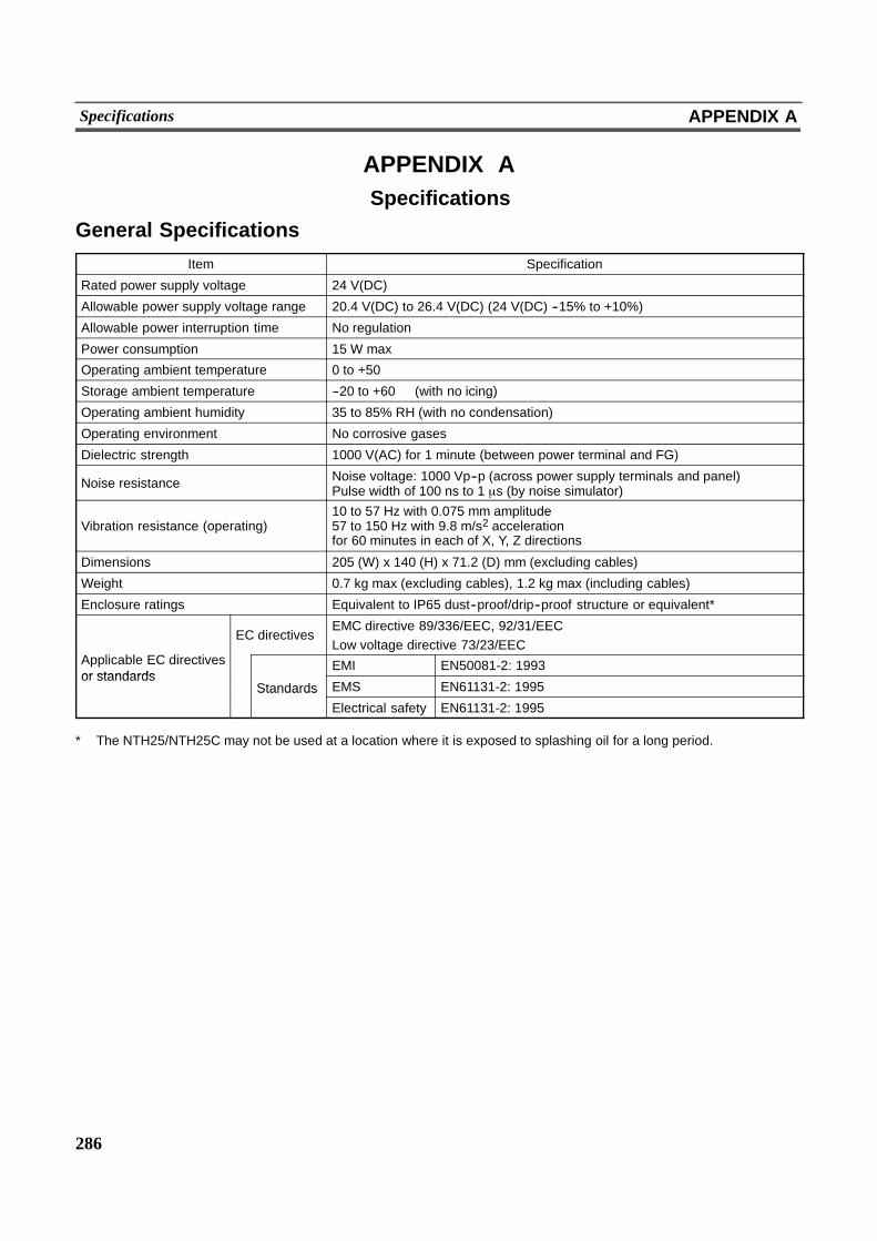
286
Specifications APPENDIX A
APPENDIX ASpecifications
General Specifications
Item Specification
Rated power supply voltage 24 V(DC)
Allowable power supply voltage range 20.4 V(DC) to 26.4 V(DC) (24 V(DC) --15% to +10%)
Allowable power interruption time No regulation
Power consumption 15 W max
Operating ambient temperature 0 to +50�
Storage ambient temperature --20 to +60� (with no icing)
Operating ambient humidity 35 to 85% RH (with no condensation)
Operating environment No corrosive gases
Dielectric strength 1000 V(AC) for 1 minute (between power terminal and FG)
Noise resistance Noise voltage: 1000 Vp--p (across power supply terminals and panel)Pulse width of 100 ns to 1 )s (by noise simulator)
Vibration resistance (operating)10 to 57 Hz with 0.075 mm amplitude57 to 150 Hz with 9.8 m/s2 accelerationfor 60 minutes in each of X, Y, Z directions
Dimensions 205 (W) x 140 (H) x 71.2 (D) mm (excluding cables)
Weight 0.7 kg max (excluding cables), 1.2 kg max (including cables)
Enclosure ratings Equivalent to IP65 dust--proof/drip--proof structure or equivalent*
EC directivesEMC directive 89/336/EEC, 92/31/EECLow voltage directive 73/23/EEC
Applicable EC directivesor standards
EMI EN50081-2: 1993or standards
Standards EMS EN61131-2: 1995StandardsElectrical safety EN61131-2: 1995
* The NTH25/NTH25C may not be used at a location where it is exposed to splashing oil for a long period.

287
Specifications APPENDIX A
Performance SpecificationsDisplay Specifications
Item Specification
Display deviceNTH25: Monocrome STN LCD (with backlight)NTH25C: Color STN LCD (with backlight)
Number of dots (resolution) 320 dots horizontally x 240 dots vertically
Size of a double--width character 4.8 mm
Effective display area (H) x (V) 96 x 72 (4.7 inches)
Display panel View angle NTH25: Up: 30* Down: 20* Left/right: +30*NTH25C: Up: 30* Down: 30* Left/right: +50*
Display colorNTH25: Black, white (2 colors)NTH25C: 8 colors (and intermediate colors can be displayed with tilingpatterns)
Life expectancy (until contrast isreduced by half) 50,000 hours minimum
Contrast adjustment Adjustable in 3 levels by operation at the touch panel
Backlight(white cold
Life expectancy* 10,000 minimum(white coldcathode tube) Replacement Not possible
POWER (green LED) Lit while power is being supplied
Indicators + (green LED) Switched between alternate and momentary by settings on NTHIndicators-- (green LED)
Switched between alternate and momentary by settings on NTHScreen Data Converter.
* Time taken for brightness to reduce to half at normal temperature and humidity
Panel Specifications
Item Specification
Type: Resistive type
Number of switches: 192 (16 horizontally x 12 vertically)Maximum number that can be registered to one screen: 192
Touch panel Cell size: 6 x 6 mmTouch panelInput: Pressure--sensitive type
Operating force: 1 N minimum
Life expectancy: 1 million operations minimum
Function switch No. of switches: 13
Push lock switch No. of switches: 1
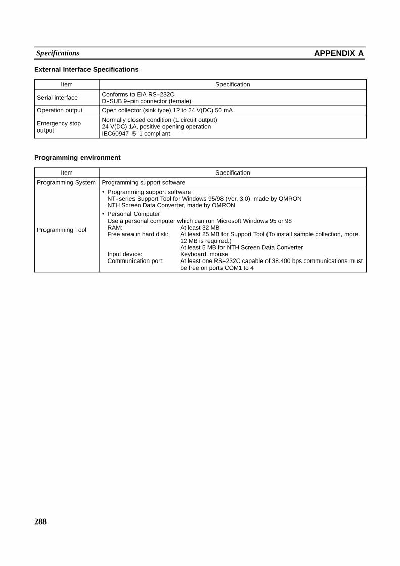
288
Specifications APPENDIX A
External Interface Specifications
Item Specification
Serial interface Conforms to EIA RS--232CD--SUB 9--pin connector (female)
Operation output Open collector (sink type) 12 to 24 V(DC) 50 mA
Emergency stopoutput
Normally closed condition (1 circuit output)24 V(DC) 1A, positive opening operationIEC60947--5--1 compliant
Programming environment
Item Specification
Programming System Programming support software
Programming Tool
! Programming support softwareNT--series Support Tool for Windows 95/98 (Ver. 3.0), made by OMRONNTH Screen Data Converter, made by OMRON
! Personal ComputerUse a personal computer which can run Microsoft Windows 95 or 98RAM: At least 32 MBFree area in hard disk: At least 25 MB for Support Tool (To install sample collection, more
12 MB is required.)At least 5 MB for NTH Screen Data Converter
Input device: Keyboard, mouseCommunication port: At least one RS--232C capable of 38.400 bps communications must
be free on ports COM1 to 4
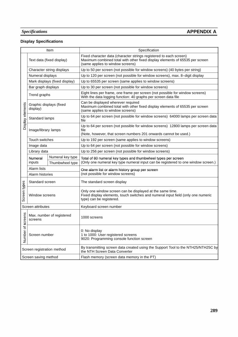
289
Specifications APPENDIX A
Display Specifications
Item Specification
Text data (fixed display)Fixed character data (character strings registered to each screen)Maximum combined total with other fixed display elements of 65535 per screen(same applies to window screens)
Character string displays Up to 50 per screen (not possible for window screens) (40 bytes per string)
Numeral displays Up to 120 per screen (not possible for window screens), max. 8--digit display
Mark displays (fixed display) Up to 65535 per screen (same applies to window screens)
Bar graph displays Up to 30 per screen (not possible for window screens)
Trend graphs Eight lines per frame, one frame per screen (not possible for window screens)With the data logging function: 40 graphs per screen data file
ements Graphic displays (fixed
display)
Can be displayed wherever requiredMaximum combined total with other fixed display elements of 65535 per screen(same applies to window screens)
play
ele
Standard lamps Up to 64 per screen (not possible for window screens) 64000 lamps per screen datafile
Displa
Image/library lampsUp to 64 per screen (not possible for window screens) 12800 lamps per screen datafile(Note, however, that screen numbers 201 onwards cannot be used.)
Touch switches Up to 192 per screen (same applies to window screens)
Image data Up to 64 per screen (not possible for window screens)
Library data Up to 256 per screen (not possible for window screens)
Numeral Numeral key type Total of 80 numeral key types and thumbwheel types per screenNumeralinputs Thumbwheel type
Total of 80 numeral key types and thumbwheel types per screen(Only one numeral key type numeral input can be registered to one window screen.)
Alarm lists One alarm list or alarm history group per screenAlarm histories
One alarm list or alarm history group per screen(not possible for window screens)
pes Standard screen The standard screen display
Screentyp
Window screensOnly one window screen can be displayed at the same time.Fixed display elements, touch switches and numeral input field (only one numerictype) can be registered.
Screen attributes Keyboard screen number
screens
Max. number of registeredscreens 1000 screens
Num
berofs
Screen number0: No display1 to 1000: User registered screens9020: Programming console function screen
Screen registration method By transmitting screen data created using the Support Tool to the NTH25/NTH25C bythe NTH Screen Data Converter
Screen saving method Flash memory (screen data memory in the PT)
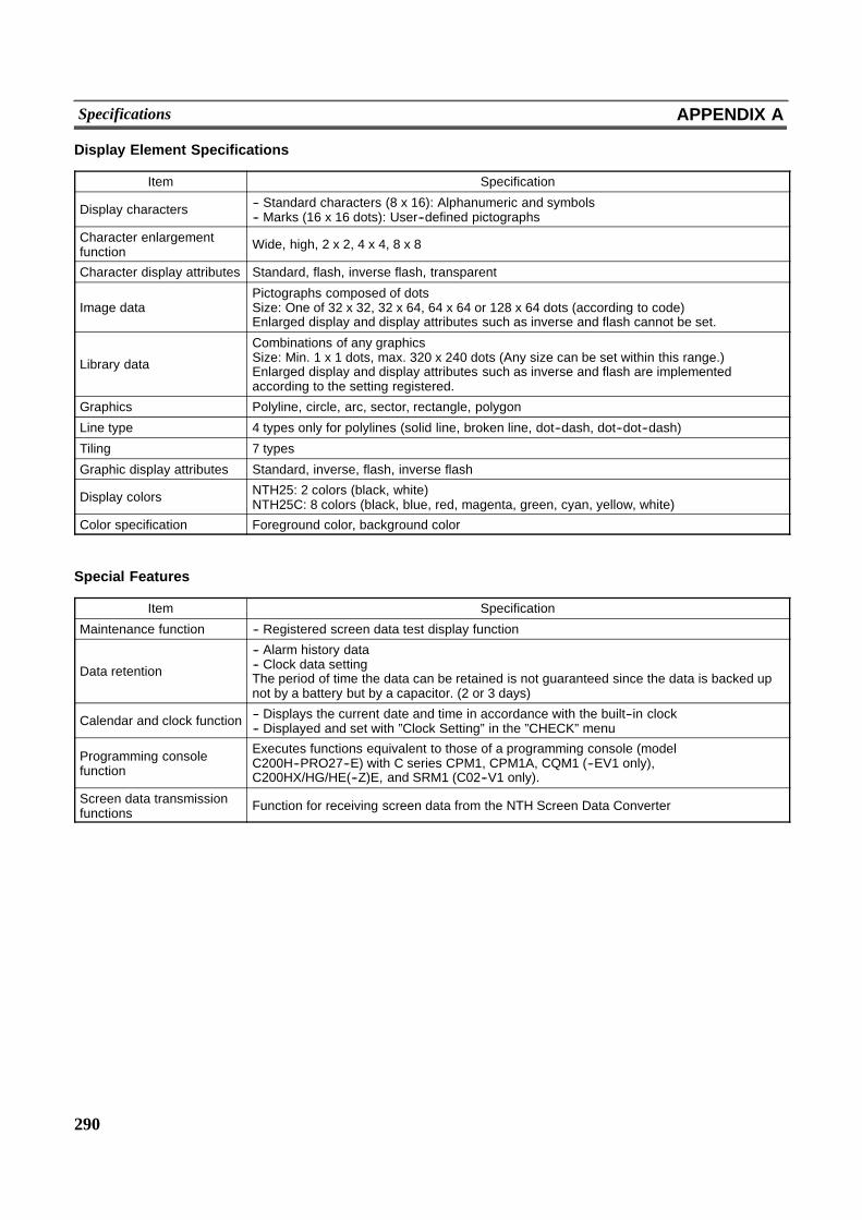
290
Specifications APPENDIX A
Display Element Specifications
Item Specification
Display characters -- Standard characters (8 x 16): Alphanumeric and symbols-- Marks (16 x 16 dots): User--defined pictographs
Character enlargementfunction Wide, high, 2 x 2, 4 x 4, 8 x 8
Character display attributes Standard, flash, inverse flash, transparent
Image dataPictographs composed of dotsSize: One of 32 x 32, 32 x 64, 64 x 64 or 128 x 64 dots (according to code)Enlarged display and display attributes such as inverse and flash cannot be set.
Library data
Combinations of any graphicsSize: Min. 1 x 1 dots, max. 320 x 240 dots (Any size can be set within this range.)Enlarged display and display attributes such as inverse and flash are implementedaccording to the setting registered.
Graphics Polyline, circle, arc, sector, rectangle, polygon
Line type 4 types only for polylines (solid line, broken line, dot--dash, dot--dot--dash)
Tiling 7 types
Graphic display attributes Standard, inverse, flash, inverse flash
Display colors NTH25: 2 colors (black, white)NTH25C: 8 colors (black, blue, red, magenta, green, cyan, yellow, white)
Color specification Foreground color, background color
Special Features
Item Specification
Maintenance function -- Registered screen data test display function
Data retention
-- Alarm history data-- Clock data settingThe period of time the data can be retained is not guaranteed since the data is backed upnot by a battery but by a capacitor. (2 or 3 days)
Calendar and clock function -- Displays the current date and time in accordance with the built--in clock-- Displayed and set with ”Clock Setting” in the ”CHECK” menu
Programming consolefunction
Executes functions equivalent to those of a programming console (modelC200H--PRO27--E) with C series CPM1, CPM1A, CQM1 (--EV1 only),C200HX/HG/HE(--Z)E, and SRM1 (C02--V1 only).
Screen data transmissionfunctions Function for receiving screen data from the NTH Screen Data Converter
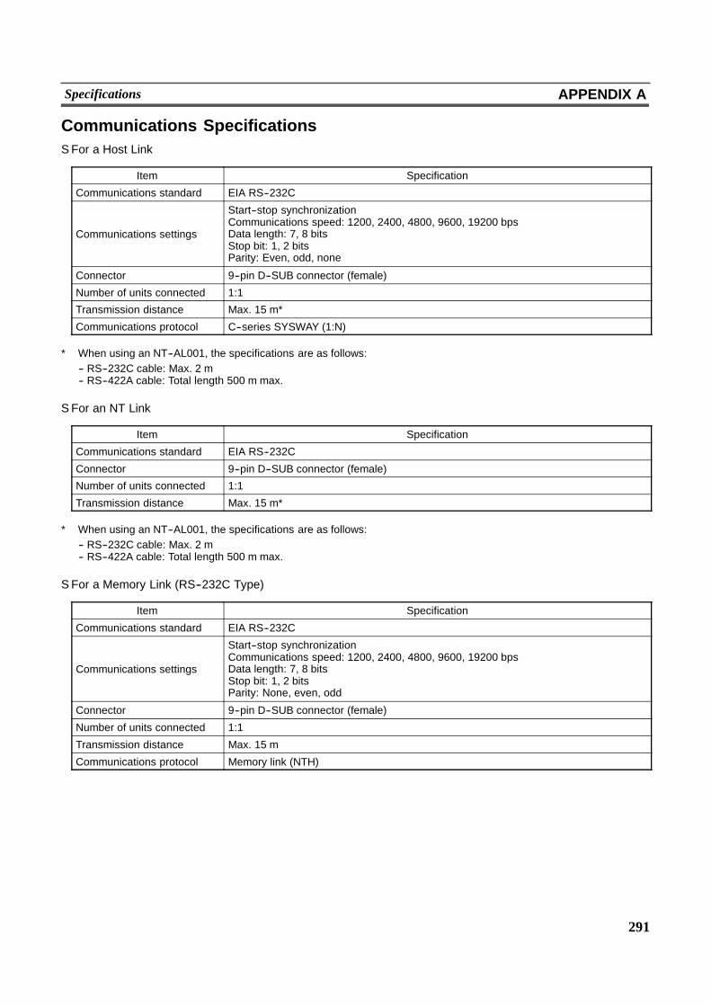
291
Specifications APPENDIX A
Communications SpecificationsS For a Host Link
Item Specification
Communications standard EIA RS--232C
Communications settings
Start--stop synchronizationCommunications speed: 1200, 2400, 4800, 9600, 19200 bpsData length: 7, 8 bitsStop bit: 1, 2 bitsParity: Even, odd, none
Connector 9--pin D--SUB connector (female)
Number of units connected 1:1
Transmission distance Max. 15 m*
Communications protocol C--series SYSWAY (1:N)
* When using an NT--AL001, the specifications are as follows:-- RS--232C cable: Max. 2 m-- RS--422A cable: Total length 500 m max.
S For an NT Link
Item Specification
Communications standard EIA RS--232C
Connector 9--pin D--SUB connector (female)
Number of units connected 1:1
Transmission distance Max. 15 m*
* When using an NT--AL001, the specifications are as follows:-- RS--232C cable: Max. 2 m-- RS--422A cable: Total length 500 m max.
S For a Memory Link (RS--232C Type)
Item Specification
Communications standard EIA RS--232C
Communications settings
Start--stop synchronizationCommunications speed: 1200, 2400, 4800, 9600, 19200 bpsData length: 7, 8 bitsStop bit: 1, 2 bitsParity: None, even, odd
Connector 9--pin D--SUB connector (female)
Number of units connected 1:1
Transmission distance Max. 15 m
Communications protocol Memory link (NTH)
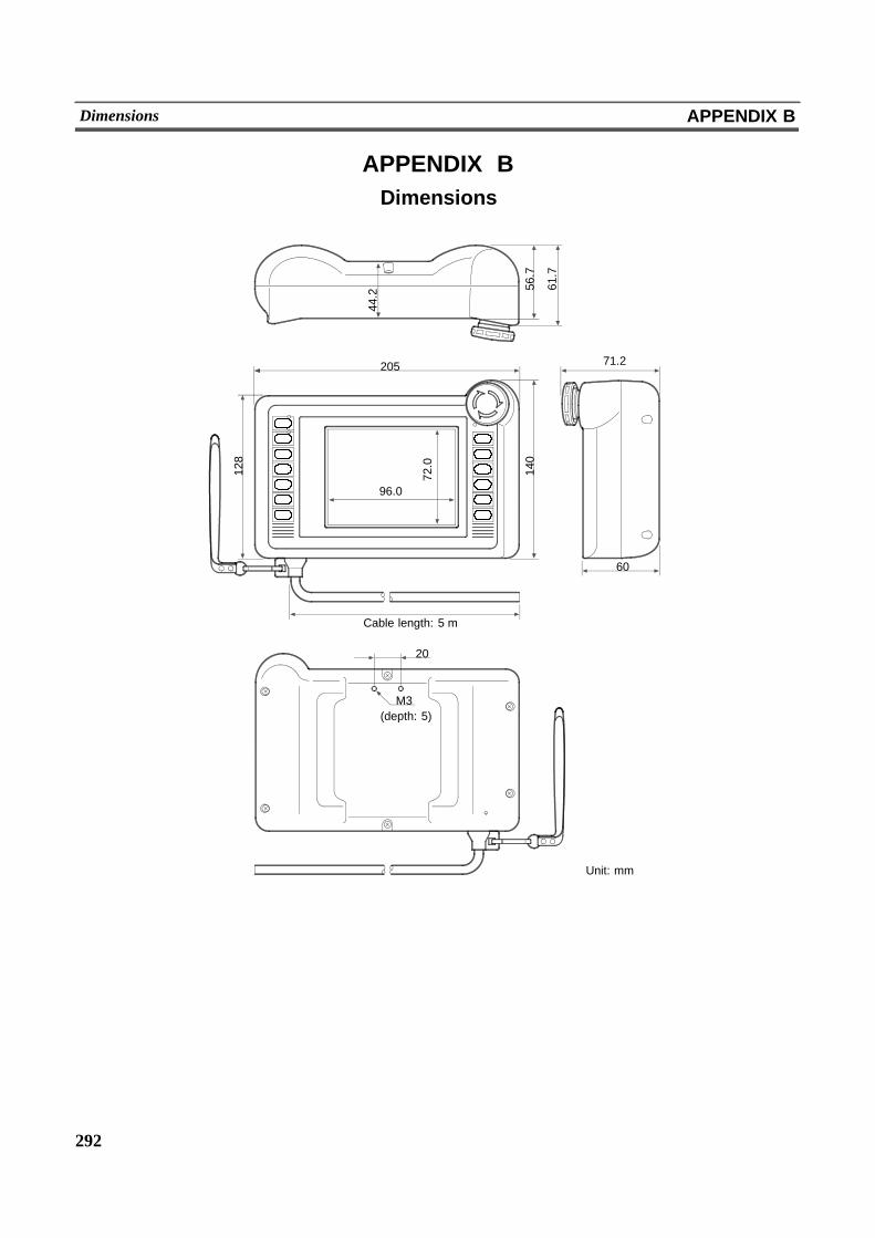
292
Dimensions APPENDIX B
APPENDIX BDimensions
20544.2
56.7
61.7
72.0
96.0
Cable length: 5 m
20
M3
71.2
140
60
(depth: 5)
Unit: mm
128
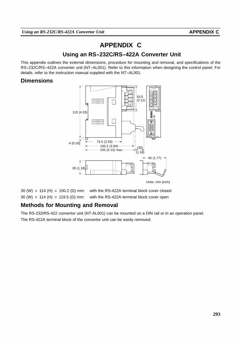
293
Using an RS-232C/RS-422A Convertor Unit APPENDIX C
APPENDIX CUsing an RS--232C/RS--422A Converter Unit
This appendix outlines the external dimensions, procedure for mounting and removal, and specifications of theRS--232C/RS--422A converter unit (NT--AL001). Refer to this information when designing the control panel. Fordetails, refer to the instruction manual supplied with the NT--AL001.
Dimensions
om onR NT--AL001
100.2 (3.94)74.5 (2.93)
110 (4.33)
4 (0.16)
30 (1.18)
45 (1.77)
53.5(2.11)
(30)(1.18)
105 (4.13) max.
Units: mm (inch)
30 (W) × 114 (H) × 100.2 (D) mm: with the RS-422A terminal block cover closed
30 (W) × 114 (H) × 119.5 (D) mm: with the RS-422A terminal block cover open
Methods for Mounting and RemovalThe RS-232/RS-422 convertor unit (NT-AL001) can be mounted on a DIN rail or in an operation panel.
The RS-422A terminal block of the convertor unit can be easily removed.
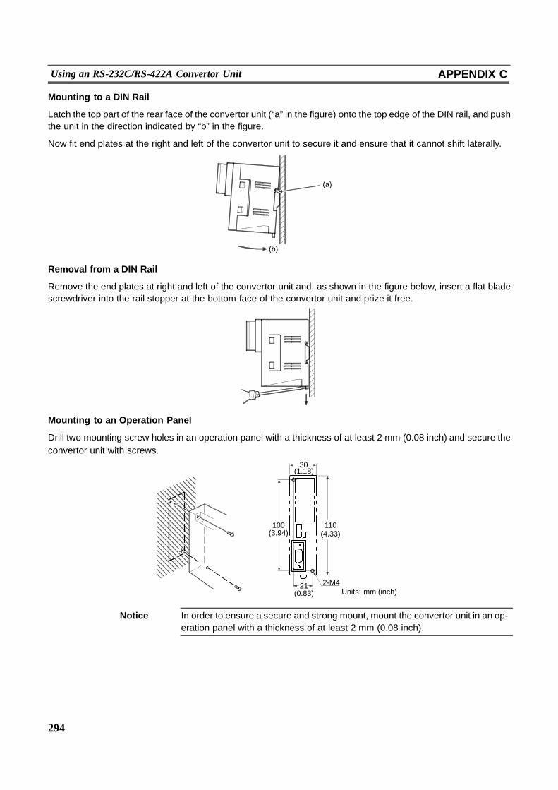
294
Using an RS-232C/RS-422A Convertor Unit APPENDIX C
Mounting to a DIN Rail
Latch the top part of the rear face of the convertor unit (“a” in the figure) onto the top edge of the DIN rail, and pushthe unit in the direction indicated by “b” in the figure.
Now fit end plates at the right and left of the convertor unit to secure it and ensure that it cannot shift laterally.
(b)
(a)
Removal from a DIN Rail
Remove the end plates at right and left of the convertor unit and, as shown in the figure below, insert a flat bladescrewdriver into the rail stopper at the bottom face of the convertor unit and prize it free.
Mounting to an Operation Panel
Drill two mounting screw holes in an operation panel with a thickness of at least 2 mm (0.08 inch) and secure theconvertor unit with screws.
(1.18)30
21
100(3.94)
110(4.33)
2-M4Units: mm (inch)(0.83)
Notice In order to ensure a secure and strong mount, mount the convertor unit in an op-eration panel with a thickness of at least 2 mm (0.08 inch).
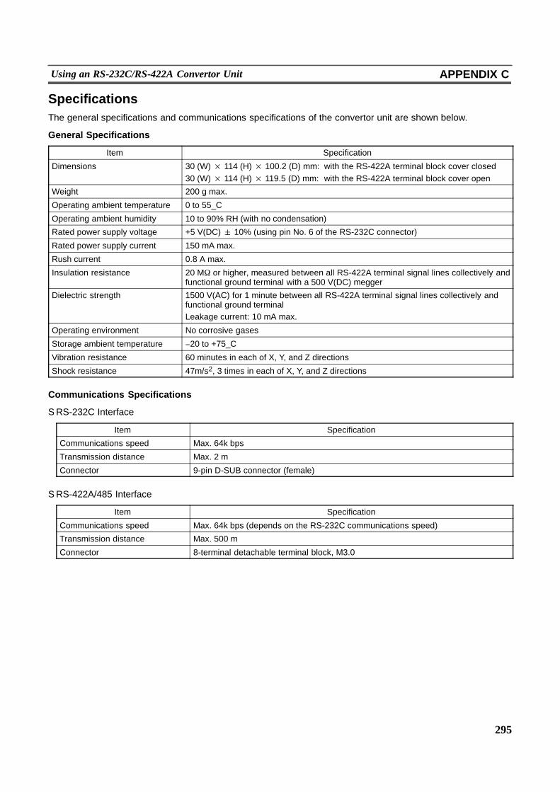
295
Using an RS-232C/RS-422A Convertor Unit APPENDIX C
SpecificationsThe general specifications and communications specifications of the convertor unit are shown below.
General Specifications
Item Specification
Dimensions 30 (W) × 114 (H) × 100.2 (D) mm: with the RS-422A terminal block cover closed30 (W) × 114 (H) × 119.5 (D) mm: with the RS-422A terminal block cover open
Weight 200 g max.
Operating ambient temperature 0 to 55_C
Operating ambient humidity 10 to 90% RH (with no condensation)
Rated power supply voltage +5 V(DC) 10% (using pin No. 6 of the RS-232C connector)
Rated power supply current 150 mA max.
Rush current 0.8 A max.
Insulation resistance 20 M, or higher, measured between all RS-422A terminal signal lines collectively andfunctional ground terminal with a 500 V(DC) megger
Dielectric strength 1500 V(AC) for 1 minute between all RS-422A terminal signal lines collectively andfunctional ground terminalLeakage current: 10 mA max.
Operating environment No corrosive gases
Storage ambient temperature (20 to +75_C
Vibration resistance 60 minutes in each of X, Y, and Z directions
Shock resistance 47m/s2, 3 times in each of X, Y, and Z directions
Communications Specifications
S RS-232C Interface
Item Specification
Communications speed Max. 64k bps
Transmission distance Max. 2 m
Connector 9-pin D-SUB connector (female)
S RS-422A/485 Interface
Item Specification
Communications speed Max. 64k bps (depends on the RS-232C communications speed)
Transmission distance Max. 500 m
Connector 8-terminal detachable terminal block, M3.0
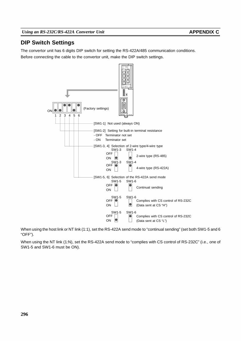
296
Using an RS-232C/RS-422A Convertor Unit APPENDIX C
DIP Switch SettingsThe convertor unit has 6 digits DIP switch for setting the RS-422A/485 communication conditions.
Before connecting the cable to the convertor unit, make the DIP switch settings.
1 2 3 4 5 6
OFFON
SW1-3 SW1-4
ONom onR NT--AL001
(Factory settings)
[SW1-1] Not used (always ON)
[SW1-2] Setting for built-in terminal resistance- OFF Terminator not set- ON Terminator set
[SW1-3, 4] Selection of 2-wire type/4-wire type
2-wire type (RS-485)
SW1-3 SW1-4OFFON 4-wire type (RS-422A)
SW1-5 SW1-6
SW1-5 SW1-6
SW1-5 SW1-6
[SW1-5, 6] Selection of the RS-422A send mode
Continual sending
Complies with CS control of RS-232C(Data sent at CS “H”)
Complies with CS control of RS-232C(Data sent at CS “L”)
OFFON
OFFON
OFFON
When using the host link or NT link (1:1), set the RS-422A sendmode to “continual sending” (set both SW1-5 and 6“OFF”).
When using the NT link (1:N), set the RS-422A send mode to “complies with CS control of RS-232C” (i.e., one ofSW1-5 and SW1-6 must be ON).
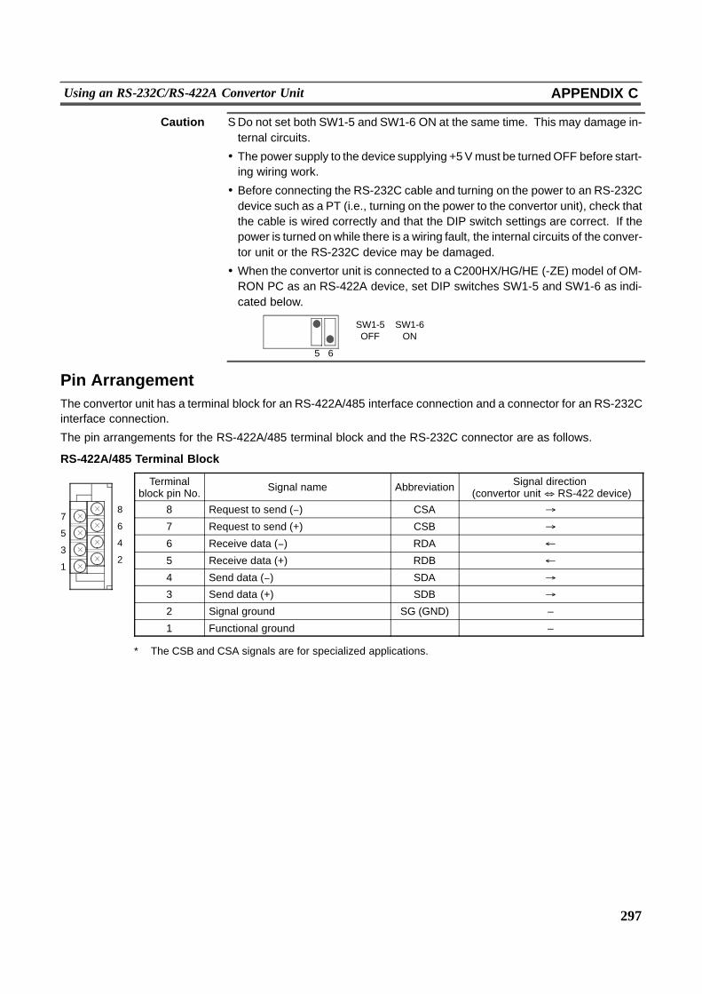
7
5
3
1
8
6
4
2
297
Using an RS-232C/RS-422A Convertor Unit APPENDIX C
Caution S Do not set both SW1-5 and SW1-6 ON at the same time. This may damage in-ternal circuits.
! The power supply to the device supplying +5Vmust be turnedOFF before start-ing wiring work.
! Before connecting the RS-232C cable and turning on the power to an RS-232Cdevice such as a PT (i.e., turning on the power to the convertor unit), check thatthe cable is wired correctly and that the DIP switch settings are correct. If thepower is turned onwhile there is a wiring fault, the internal circuits of the conver-tor unit or the RS-232C device may be damaged.
! When the convertor unit is connected to a C200HX/HG/HE (-ZE) model of OM-RON PC as an RS-422A device, set DIP switches SW1-5 and SW1-6 as indi-cated below.
5 6
SW1-5OFF
SW1-6ON
Pin ArrangementThe convertor unit has a terminal block for an RS-422A/485 interface connection and a connector for an RS-232Cinterface connection.
The pin arrangements for the RS-422A/485 terminal block and the RS-232C connector are as follows.
RS-422A/485 Terminal Block
Terminalblock pin No. Signal name Abbreviation Signal direction
(convertor unit& RS-422 device)
8 Request to send (() CSA %
7 Request to send (+) CSB %
6 Receive data (() RDA "
5 Receive data (+) RDB "
4 Send data (() SDA %
3 Send data (+) SDB %
2 Signal ground SG (GND) –
1 Functional ground –
* The CSB and CSA signals are for specialized applications.
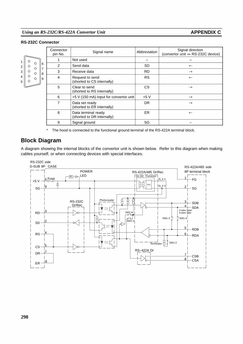
6
7
8
9
1
2
3
4
5
298
Using an RS-232C/RS-422A Convertor Unit APPENDIX C
RS-232C Connector
Connectorpin No. Signal name Abbreviation Signal direction
(convertor unit& RS-232C device)
1 Not used – –
2 Send data SD "
3 Receive data RD %
4 Request to send(shorted to CS internally)
RS "
5 Clear to send(shorted to RS internally)
CS %
6 +5 V (150 mA) input for convertor unit +5 V %
7 Data set ready(shorted to ER internally)
DR %
8 Data terminal ready(shorted to DR internally)
ER "
9 Signal ground SG –
* The hood is connected to the functional ground terminal of the RS-422A terminal block.
Block DiagramA diagram showing the internal blocks of the convertor unit is shown below. Refer to this diagram when makingcables yourself, or when connecting devices with special interfaces.
SW1-6
Terminator
R
R
D-SUB 9P CASE
+5 V
SG
SD
RD
RS
CS
DR
ER
6
9
2
3
4
5
7
8
POWERLED
RS-232CDr/Rec
RS-422A/485 Dr/RecDC-DC
IS_5 V
IS_0 V
FG1
2
34
6
5
78
SW1-5SW1-4
SG
SDBSDA
RDB
RDA
CSBCSA
SW1-2
RS--422A Dr
SW1-3
RS-232C side
FuseConvertor
RS-422A/485 side8P terminal block
Photocoupler
2-wire type/4-wire type
R R
R
R
L L REG

299
Transporting and Storing the NTH25/NTH25C APPENDIX D
APPENDIX DTransporting and Storing the NTH25/NTH25C
S When transporting the NTH25/NTH25C, use the packaging intended for it.
S When storing the NTH25/NTH25C, observe the following conditions.
Storage ambient temperature: (20 to +60_C
Storage ambient humidity: 35 to 85% RH
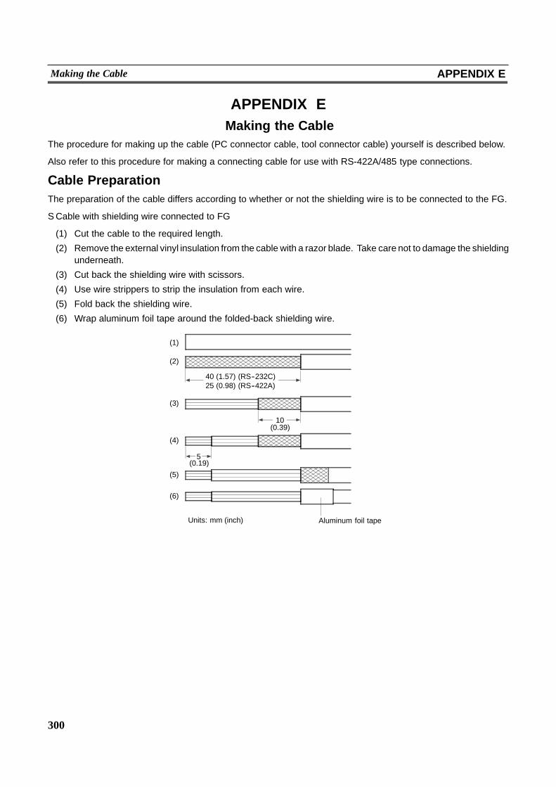
300
Making the Cable APPENDIX E
APPENDIX EMaking the Cable
The procedure for making up the cable (PC connector cable, tool connector cable) yourself is described below.
Also refer to this procedure for making a connecting cable for use with RS-422A/485 type connections.
Cable PreparationThe preparation of the cable differs according to whether or not the shielding wire is to be connected to the FG.
S Cable with shielding wire connected to FG
(1) Cut the cable to the required length.
(2) Remove the external vinyl insulation from the cable with a razor blade. Take care not to damage the shieldingunderneath.
(3) Cut back the shielding wire with scissors.
(4) Use wire strippers to strip the insulation from each wire.
(5) Fold back the shielding wire.
(6) Wrap aluminum foil tape around the folded-back shielding wire.
40 (1.57) (RS--232C)25 (0.98) (RS--422A)
10
5
Units: mm (inch) Aluminum foil tape
(1)
(2)
(3)
(4)
(5)
(6)
(0.19)
(0.39)
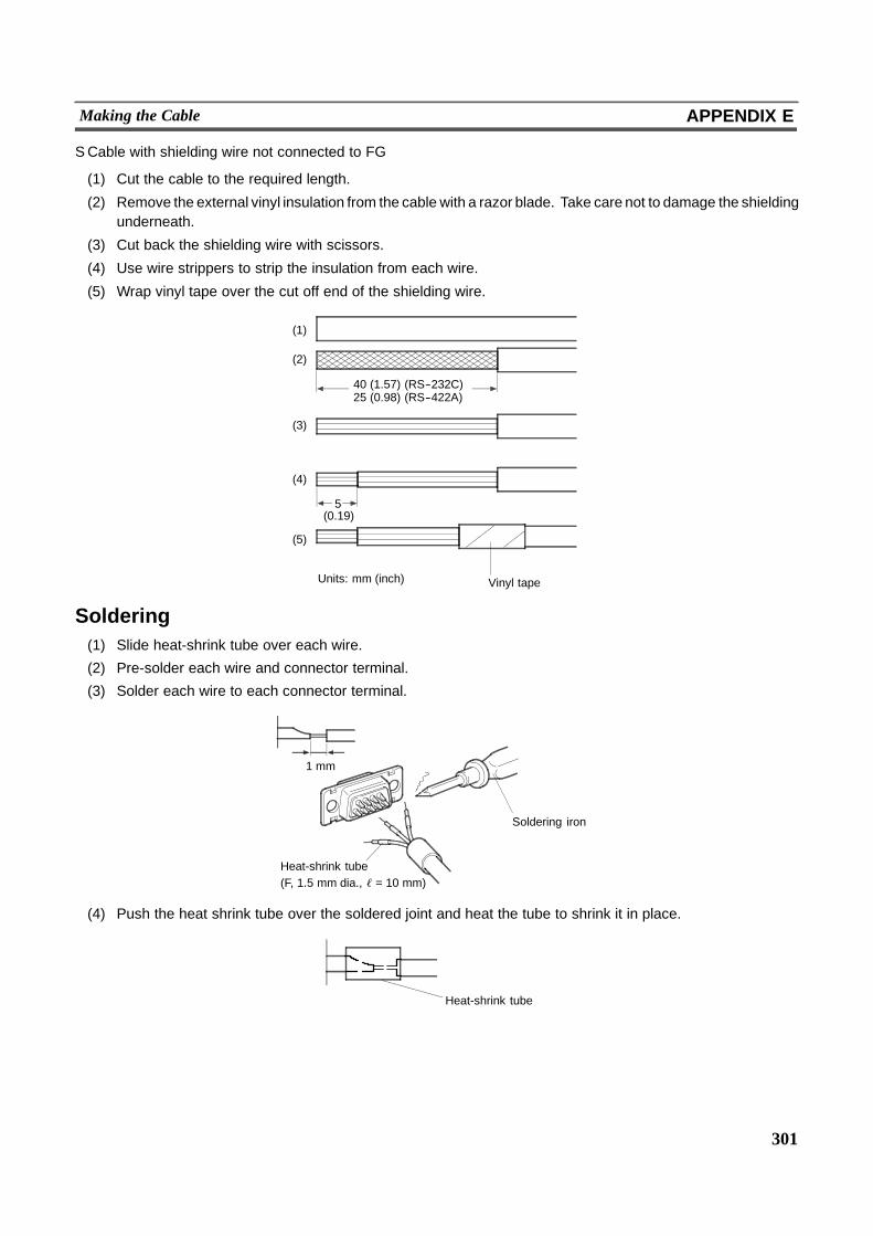
301
Making the Cable APPENDIX E
S Cable with shielding wire not connected to FG
(1) Cut the cable to the required length.
(2) Remove the external vinyl insulation from the cable with a razor blade. Take care not to damage the shieldingunderneath.
(3) Cut back the shielding wire with scissors.
(4) Use wire strippers to strip the insulation from each wire.
(5) Wrap vinyl tape over the cut off end of the shielding wire.
40 (1.57) (RS--232C)
5
25 (0.98) (RS--422A)
(1)
(2)
(3)
(4)
(5)
Units: mm (inch) Vinyl tape
(0.19)
Soldering(1) Slide heat-shrink tube over each wire.
(2) Pre-solder each wire and connector terminal.
(3) Solder each wire to each connector terminal.
Soldering iron
Heat-shrink tube(F, 1.5 mm dia., ℓ = 10 mm)
1 mm
(4) Push the heat shrink tube over the soldered joint and heat the tube to shrink it in place.
Heat-shrink tube
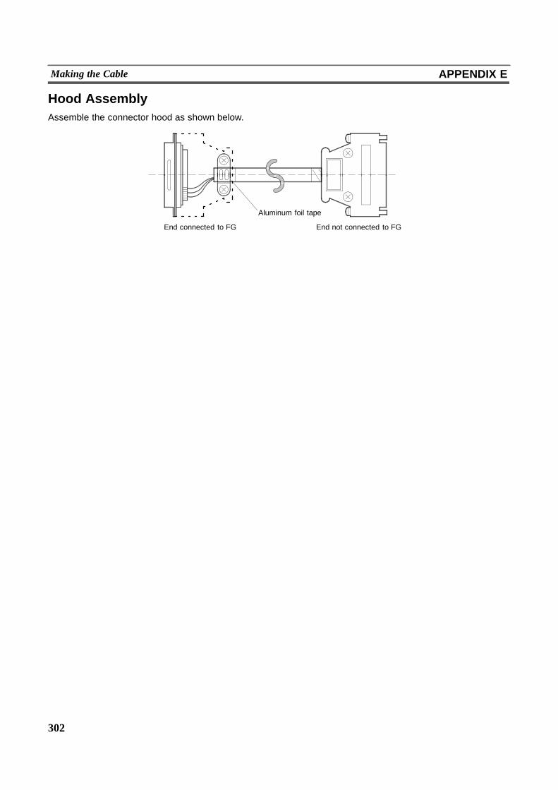
302
Making the Cable APPENDIX E
Hood AssemblyAssemble the connector hood as shown below.
Aluminum foil tape
End connected to FG End not connected to FG
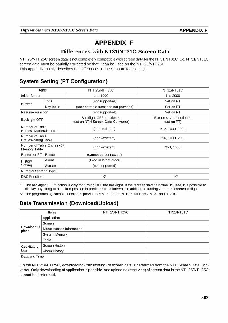
303
Differences with NT31/NT31C Screen Data APPENDIX F
APPENDIX FDifferences with NT31/NT31C Screen Data
NTH25/NTH25C screen data is not completely compatible with screen data for theNT31/NT31C. So, NT31/NT31Cscreen data must be partially corrected so that it can be used on the NTH25/NTH25C.This appendix mainly describes the differences in the Support Tool settings.
System Setting (PT Configuration)
Items NTH25/NTH25C NT31/NT31C
Initial Screen 1 to 1000 1 to 3999
BuzzerTone � (not supported) Set on PT
BuzzerKey Input � (user settable functions not provided) Set on PT
Resume Function � (not supported) Set on PT
Backlight OFF Backlight OFF function *1(set on NTH Screen Data Converter)
Screen saver function *1(set on PT)
Number of TableEntries--Numeral Table � (non--existent) 512, 1000, 2000
Number of TableEntries--String Table � (non--existent) 256, 1000, 2000
Number of Table Entries--BitMemory Table � (non--existent) 250, 1000
Printer for PT Printer � (cannot be connected) �
History Alarm � (fixed in latest order) �HistorySetting Screen � (not supported) �
Numeral Storage Type � �
DAC Function � *2 � *2
*1 The backlight OFF function is only for turning OFF the backlight. If the ”screen saver function” is used, it is possible todisplay any string at a desired position in predetermined intervals in addition to turning OFF the screen/backlight.
*2 The programming console function is provided as standard on NTH25, NTH25C, NT31 and NT31C.
Data Transmission (Download/Upload)
Items NTH25/NTH25C NT31/NT31C
Application � �
D l d/UScreen � �
Download/Upload Direct Access Information � �pload
System Memory � �
Table � �
Get History Screen History � �Get HistoryLog Alarm History � �
Data and Time � �
On the NTH25/NTH25C, downloading (transmitting) of screen data is performed from the NTH Screen Data Con-verter. Only downloading of application is possible, and uploading (receiving) of screen data in theNTH25/NTH25Ccannot be performed.
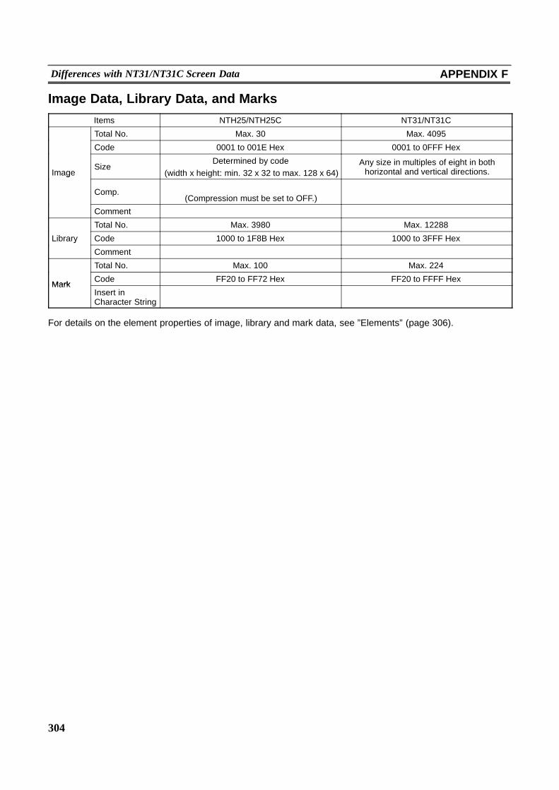
304
Differences with NT31/NT31C Screen Data APPENDIX F
Image Data, Library Data, and Marks
Items NTH25/NTH25C NT31/NT31C
Total No. Max. 30 Max. 4095
Code 0001 to 001E Hex 0001 to 0FFF Hex
ImageSize
Determined by code(width x height: min. 32 x 32 to max. 128 x 64)
Any size in multiples of eight in bothhorizontal and vertical directions.g
Comp.�
(Compression must be set to OFF.)�
Comment � �
Total No. Max. 3980 Max. 12288
Library Code 1000 to 1F8B Hex 1000 to 3FFF Hexy
Comment � �
Total No. Max. 100 Max. 224
MarkCode FF20 to FF72 Hex FF20 to FFFF Hex
MarkInsert inCharacter String � �
For details on the element properties of image, library and mark data, see ”Elements” (page 306).
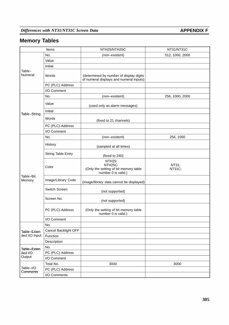
305
Differences with NT31/NT31C Screen Data APPENDIX F
Memory Tables
Items NTH25/NTH25C NT31/NT31C
No. (non--existent) 512, 1000, 2000
Value � �
Initial � �Table--Numeral Words
�(determined by number of display digitsof numeral displays and numeral inputs)
�
PC (PLC) Address � �
I/O Comment � �
No. (non--existent) 256, 1000, 2000
Value �(used only as alarm messages) �
Table StringInitial � �
Table--StringWords �
(fixed to 21 channels) �
PC (PLC) Address � �
I/O Comment � �
No. (non--existent) 256, 1000
History �(sampled at all times) �
String Table Entry �(fixed to 240) �
T bl Bit
Color
NTH25: �NTH25C: �
(Only the setting of bit memory tablenumber 0 is valid.)
NT31: �NT31C: �
Table--BitMemory Image/Library Code �
(image/library data cannot be displayed) �
Switch Screen �(not supported) �
Screen No. �(not supported) �
PC (PLC) Address�
(Only the setting of bit memory tablenumber 0 is valid.)
�
I/O Comment � �
No. � �
Table--Exten Cancel Backlight OFF � �Table--Extended I/O Input Function � �
Description � �
Table--Exten No. � �Table--Extended I/OO
PC (PLC) Address � �ded I/OOutput I/O Comment � �
Total No. 3000 3000Table--I/OComments
PC (PLC) Address � �Comments
I/O Comments � �
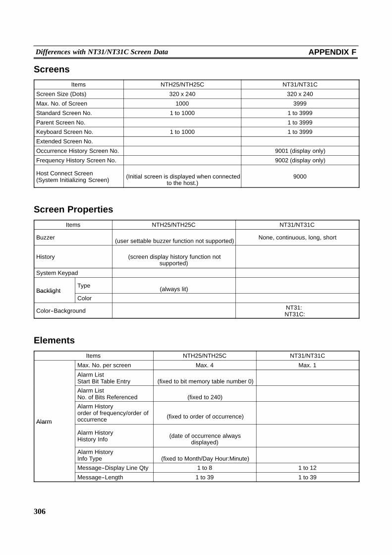
306
Differences with NT31/NT31C Screen Data APPENDIX F
Screens
Items NTH25/NTH25C NT31/NT31C
Screen Size (Dots) 320 x 240 320 x 240
Max. No. of Screen 1000 3999
Standard Screen No. 1 to 1000 1 to 3999
Parent Screen No. � 1 to 3999
Keyboard Screen No. 1 to 1000 1 to 3999
Extended Screen No. � �
Occurrence History Screen No. � 9001 (display only)
Frequency History Screen No. � 9002 (display only)
Host Connect Screen(System Initializing Screen)
�(Initial screen is displayed when connected
to the host.)9000
Screen Properties
Items NTH25/NTH25C NT31/NT31C
Buzzer �(user settable buzzer function not supported) None, continuous, long, short
History�
(screen display history function notsupported)
�
System Keypad � �
BacklightType �
(always lit) �Backlight
Color � �
Color--Background � NT31: �NT31C:�
Elements
Items NTH25/NTH25C NT31/NT31C
Max. No. per screen Max. 4 Max. 1
Alarm ListStart Bit Table Entry
�(fixed to bit memory table number 0) �
Alarm ListNo. of Bits Referenced
�(fixed to 240) �
Alarm
Alarm Historyorder of frequency/order ofoccurrence
�(fixed to order of occurrence) �
Alarm
Alarm HistoryHistory Info
�(date of occurrence always
displayed)�
Alarm HistoryInfo Type
�(fixed to Month/Day Hour:Minute) �
Message--Display Line Qty 1 to 8 1 to 12
Message--Length 1 to 39 1 to 39
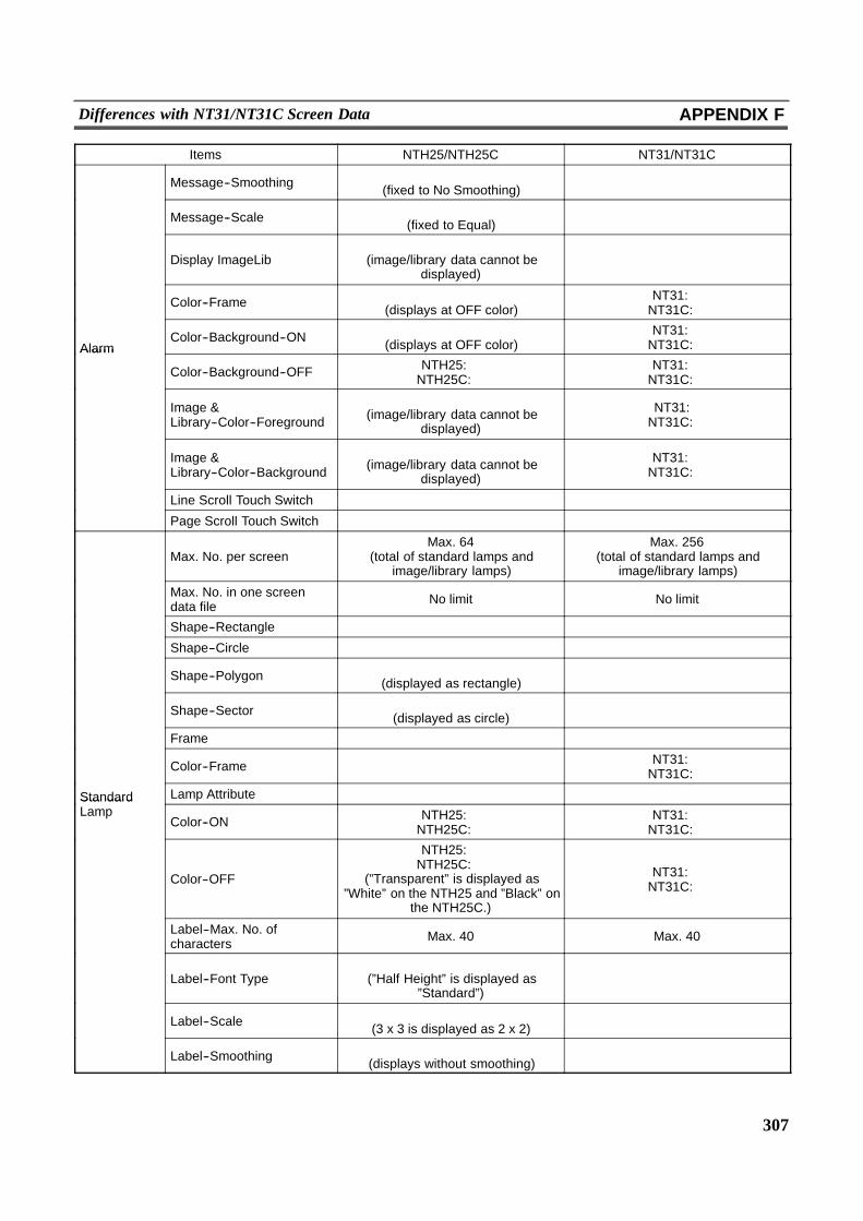
307
Differences with NT31/NT31C Screen Data APPENDIX F
Items NTH25/NTH25C NT31/NT31C
Message--Smoothing �(fixed to No Smoothing) �
Message--Scale �(fixed to Equal) �
Display ImageLib�
(image/library data cannot bedisplayed)
�
Color--Frame �(displays at OFF color)
NT31: �NT31C: �
AlarmColor--Background--ON �
(displays at OFF color)NT31: �NT31C: �Alarm
Color--Background--OFF NTH25: �NTH25C: �
NT31: �NT31C: �
Image &Library--Color--Foreground
�(image/library data cannot be
displayed)
NT31:�NT31C: �
Image &Library--Color--Background
�(image/library data cannot be
displayed)
NT31: �NT31C: �
Line Scroll Touch Switch � �
Page Scroll Touch Switch � �
Max. No. per screenMax. 64
(total of standard lamps andimage/library lamps)
Max. 256(total of standard lamps and
image/library lamps)
Max. No. in one screendata file No limit No limit
Shape--Rectangle � �
Shape--Circle � �
Shape--Polygon �(displayed as rectangle) �
Shape--Sector �(displayed as circle) �
Frame � �
Color--Frame � NT31: �NT31C: �
Standard Lamp Attribute � �StandardLamp
Color--ON NTH25: �NTH25C: �
NT31: �NT31C: �
Color--OFF
NTH25: �NTH25C: �
(”Transparent” is displayed as”White” on the NTH25 and ”Black” on
the NTH25C.)
NT31: �NT31C: �
Label--Max. No. ofcharacters Max. 40 Max. 40
Label--Font Type�
(”Half Height” is displayed as”Standard”)
�
Label--Scale �(3 x 3 is displayed as 2 x 2) �
Label--Smoothing �(displays without smoothing) �
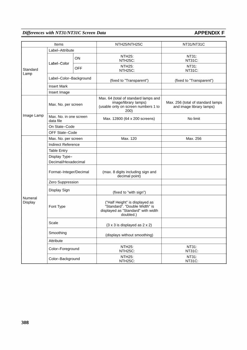
308
Differences with NT31/NT31C Screen Data APPENDIX F
Items NTH25/NTH25C NT31/NT31C
Label--Attribute � �
Label ColorON NTH25: �
NTH25C: �NT31: �NT31C: �
StandardLamp
Label--ColorOFF NTH25: �
NTH25C: �NT31: �NT31C: �
LampLabel--Color--Background �
(fixed to ”Transparent”)�
(fixed to ”Transparent”)
Insert Mark � �
Insert Image � �
Max. No. per screen
Max. 64 (total of standard lamps andimage/library lamps)
(usable only on screen numbers 1 to200)
Max. 256 (total of standard lampsand image library lamps)
Image Lamp Max. No. in one screendata file Max. 12800 (64 x 200 screens) No limit
On State--Code � �
OFF State--Code � �
Max. No. per screen Max. 120 Max. 256
Indirect Reference � �
Table Entry � �
Display Type--Decimal/Hexadecimal
� �
Format--Integer/Decimal�
(max. 8 digits including sign anddecimal point)
�
Zero Suppression � �
Display Sign �(fixed to ”with sign”) �
NumeralDisplay
Font Type
�(”Half Height” is displayed as”Standard”. ”Double Width” is
displayed as ”Standard” with widthdoubled.)
�
Scale �(3 x 3 is displayed as 2 x 2) �
Smoothing �(displays without smoothing) �
Attribute � �
Color--Foreground NTH25: �NTH25C: �
NT31: �NT31C: �
Color--Background NTH25: �NTH25C: �
NT31: �NT31C: �

309
Differences with NT31/NT31C Screen Data APPENDIX F
Items Items NTH25/NTH25C NT31/NT31C
Max. No. per screen Max. 50 Max. 256
Indirect Reference � �
Table Entry � �
Length Max. 40 Max. 40
Font Type�
(”Half Height” is displayed as”Standard”.)
�
String display Scale �(set at first allocated word) �
Smoothing �(displays without smoothing) �
Attribute �(set at first allocated word) �
Color--Foreground NTH25: �NTH25C: �
NT31: �NT31C: �
Color--Background NTH25: �NTH25C: �
NT31: �NT31C: �
Max. No. per screen Max. 80(Total with thumbwheel type) Max. 256
Table Entry � �
Display Type--Decimal/Hexadecimal
� �
Limit--Maximum � �
Limit--Minimum � �
Format--Integer/Decimal�
(max. 8 digits including decimalpoint)
�
Zero Suppression � �
Display Sign �(Minus numbers cannot be input.) �
Data Input--Numeral(NumericKey Type)
Font Type
�(”Half Height” is displayed as”Standard”. ”Double Width” is
displayed as ”Standard” with widthdoubled.)
�
Scale �(3 x 3 is displayed as 2 x 2) �
Smoothing �(displays without smoothing) �
Attribute � �
Color--Foreground NTH25: �NTH25C: �
NT31: �NT31C: �
Color--Background NTH25: �NTH25C: �
NT31: �NT31C: �
Focus Frame �(displays without cursor) �
Focus Attribute �(displays without cursor) �
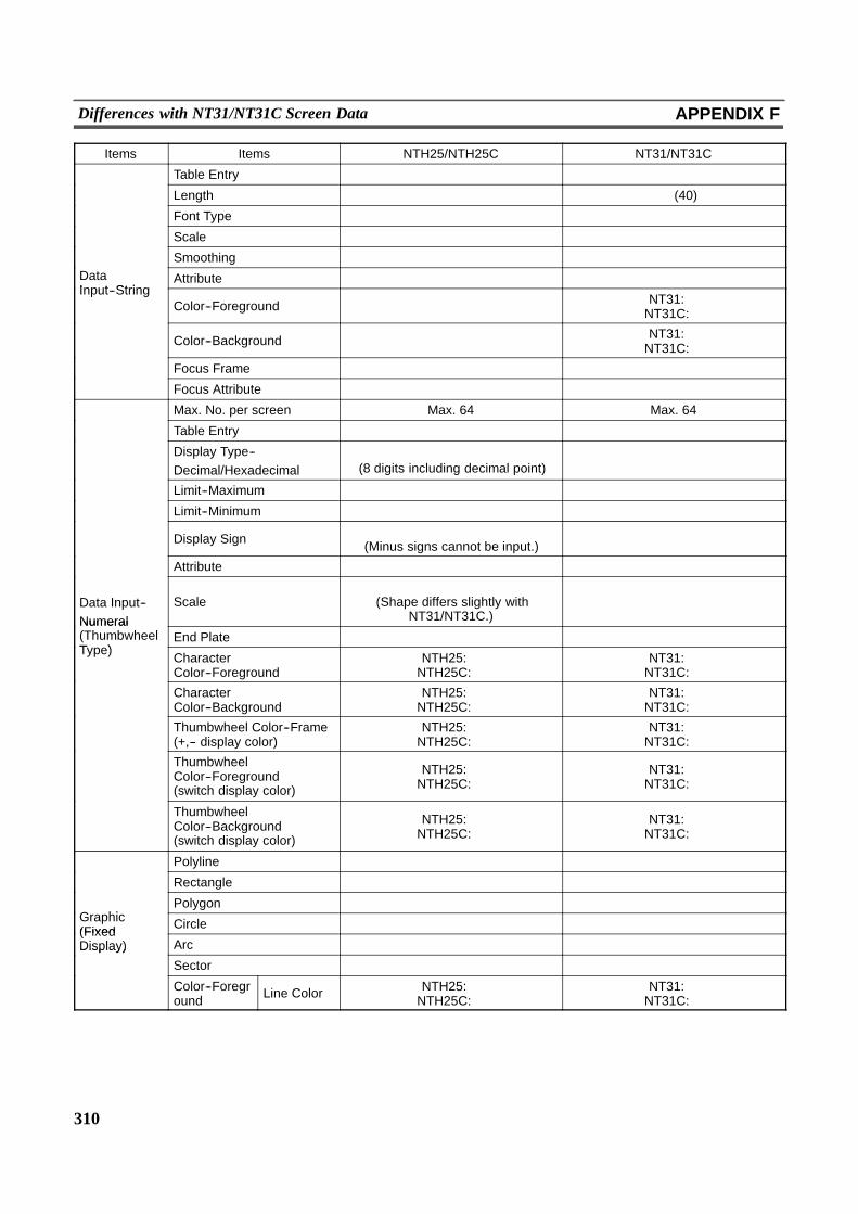
310
Differences with NT31/NT31C Screen Data APPENDIX F
Items Items NTH25/NTH25C NT31/NT31C
Table Entry � �
Length � � (40)
Font Type � �
Scale � �
Smoothing � �DataInput String
Attribute � �Input--String
Color--Foreground � NT31: �NT31C: �
Color--Background � NT31: �NT31C: �
Focus Frame � �
Focus Attribute � �
Max. No. per screen Max. 64 Max. 64
Table Entry � �
Display Type--Decimal/Hexadecimal
�(8 digits including decimal point) �
Limit--Maximum � �
Limit--Minimum � �
Display Sign �(Minus signs cannot be input.) �
Attribute � �
Data Input--Numeral
Scale�
(Shape differs slightly withNT31/NT31C.)
�
Numeral(ThumbwheelT )
End Plate � �(Type)
CharacterColor--Foreground
NTH25: �NTH25C: �
NT31: �NT31C: �
CharacterColor--Background
NTH25: �NTH25C: �
NT31: �NT31C: �
Thumbwheel Color--Frame(+,-- display color)
NTH25: �NTH25C: �
NT31: �NT31C: �
ThumbwheelColor--Foreground(switch display color)
NTH25: �NTH25C: �
NT31: �NT31C: �
ThumbwheelColor--Background(switch display color)
NTH25: �NTH25C: �
NT31: �NT31C: �
Polyline � �
Rectangle � �
G hiPolygon � �
Graphic(Fixed Circle � �(FixedDisplay) Arc � �Display)
Sector � �
Color--Foreground Line Color NTH25: �
NTH25C: �NT31: �NT31C: �
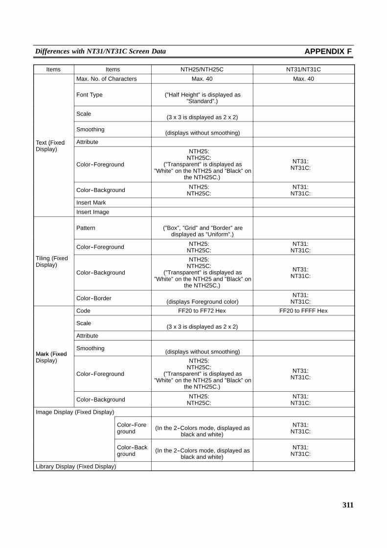
311
Differences with NT31/NT31C Screen Data APPENDIX F
Items Items NTH25/NTH25C NT31/NT31C
Max. No. of Characters Max. 40 Max. 40
Font Type�
(”Half Height” is displayed as”Standard”.)
�
Scale �(3 x 3 is displayed as 2 x 2) �
Smoothing �(displays without smoothing) �
Text (Fixed Attribute � �Text (FixedDisplay)
Color--Foreground
NTH25: �NTH25C: �
(”Transparent” is displayed as”White” on the NTH25 and ”Black” on
the NTH25C.)
NT31: �NT31C: �
Color--Background NTH25: �NTH25C: �
NT31: �NT31C: �
Insert Mark � �
Insert Image � �
Pattern�
(”Box”, ”Grid” and ”Border” aredisplayed as ”Uniform”.)
�
Color--Foreground NTH25: �NTH25C: �
NT31: �NT31C: �
Tiling (FixedDisplay)
Color--Background
NTH25: �NTH25C: �
(”Transparent” is displayed as”White” on the NTH25 and ”Black” on
the NTH25C.)
NT31: �NT31C: �
Color--Border �(displays Foreground color)
NT31: �NT31C: �
Code FF20 to FF72 Hex FF20 to FFFF Hex
Scale �(3 x 3 is displayed as 2 x 2) �
Attribute � �
Mark (FixedSmoothing �
(displays without smoothing) �Mark (FixedDisplay)
Color--Foreground
NTH25: �NTH25C: �
(”Transparent” is displayed as”White” on the NTH25 and ”Black” on
the NTH25C.)
NT31: �NT31C: �
Color--Background NTH25: �NTH25C: �
NT31: �NT31C: �
Image Display (Fixed Display) � �
Color--Foreground
�(In the 2--Colors mode, displayed as
black and white)
NT31: �NT31C: �
Color--Background
�(In the 2--Colors mode, displayed as
black and white)
NT31: �NT31C: �
Library Display (Fixed Display) � �

312
Differences with NT31/NT31C Screen Data APPENDIX F
Items Items NTH25/NTH25C NT31/NT31C
Max. No. per screen Max. 192 (overlapping of touchswitches is not allowed) Max. 256
Function--Notify Bit
�(On the host link or NT link (1:1),
”Set” and ”Reset” act as ”Momentary”switches, and on the memory link, all
act as ”Momentary switches.)
�
Function--Switch Screen � �
Function--Input Key--Control �(Some keys cannot be used.) �
Function--InputKey--Keyboard
�(”Toggle” is operated as ”Open”.) �
Function--Input Key--String �(not supported) �
Function--Copy Setting �(no memory table) �
Function--Cursor Move�
(automatically generated for numeralkey elements)
�
Function--Screen Print � �
PC (PLC) Bit Address(for lamp function)
�(no lamp function) �
Shape--Standard �(displayed as double frame) �
Touch SwitchShape--Shadow
�(normally displayed as ”double
frame”)�
Shape--3--Dimension�
(normally displayed as ”doubleframe”)
�
Shape--Rectangle �(displayed as fixed display element) �
Shape--Circle �(displayed as fixed display element) �
Shape--Polygon �(displayed as fixed display element) �
Shape--Sector �(displayed as fixed display element) �
Frame � �
Color--Frame �(displays at OFF color)
NT31: �NT31C: �
Show ON State�
(valid only when shape is set to”None” or ”Standard”)
�
Lamp Attribute �(fixed to ON) �
Color--ON�
(displayed at inverse color of ”OFFcolor”)
NT31: �NT31C: �
Color--OFF NTH25: �NTH25C: �
NT31: �NT31C: �
Max. No. of Characters 40 40
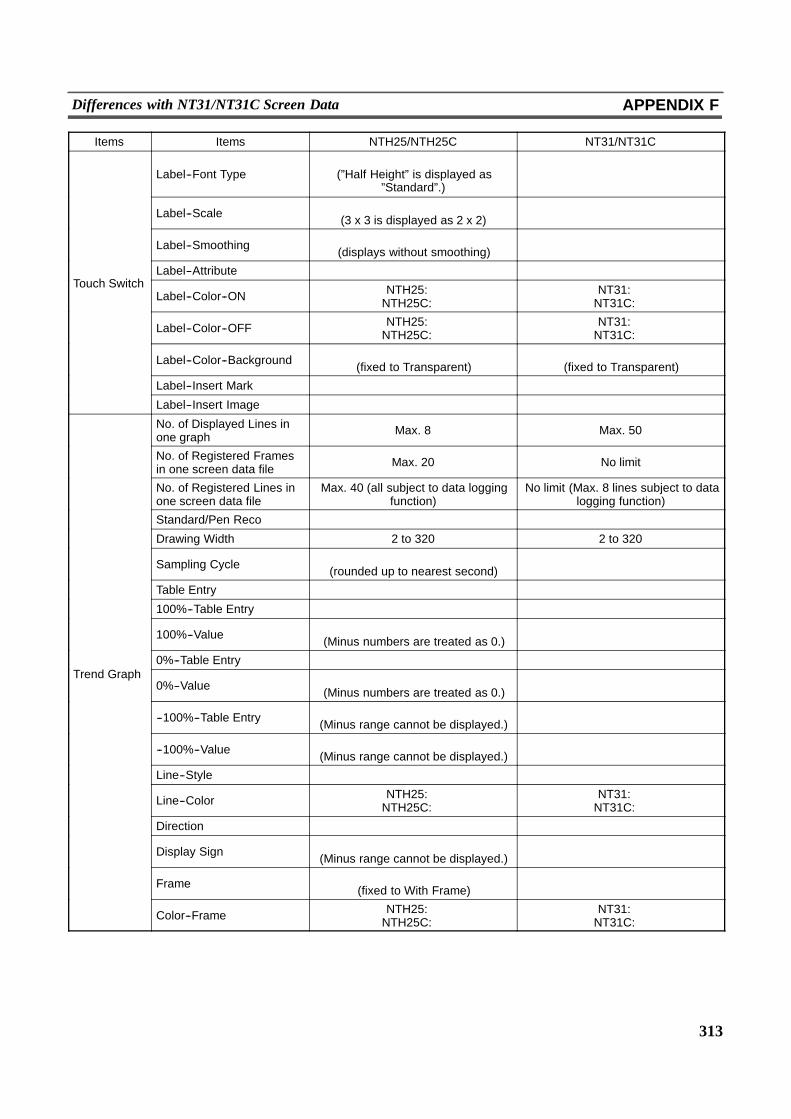
313
Differences with NT31/NT31C Screen Data APPENDIX F
Items Items NTH25/NTH25C NT31/NT31C
Label--Font Type�
(”Half Height” is displayed as”Standard”.)
�
Label--Scale �(3 x 3 is displayed as 2 x 2) �
Label--Smoothing �(displays without smoothing) �
T h S it hLabel--Attribute � �
Touch SwitchLabel--Color--ON NTH25: �
NTH25C: �NT31: �NT31C: �
Label--Color--OFF NTH25: �NTH25C: �
NT31: �NT31C: �
Label--Color--Background �(fixed to Transparent)
�(fixed to Transparent)
Label--Insert Mark � �
Label--Insert Image � �
No. of Displayed Lines inone graph Max. 8 Max. 50
No. of Registered Framesin one screen data file Max. 20 No limit
No. of Registered Lines inone screen data file
Max. 40 (all subject to data loggingfunction)
No limit (Max. 8 lines subject to datalogging function)
Standard/Pen Reco � �
Drawing Width 2 to 320 2 to 320
Sampling Cycle �(rounded up to nearest second) �
Table Entry � �
100%--Table Entry � �
100%--Value �(Minus numbers are treated as 0.) �
0%--Table Entry � �Trend Graph
0%--Value �(Minus numbers are treated as 0.) �
--100%--Table Entry �(Minus range cannot be displayed.) �
--100%--Value �(Minus range cannot be displayed.) �
Line--Style � �
Line--Color NTH25: �NTH25C: �
NT31: �NT31C: �
Direction � �
Display Sign �(Minus range cannot be displayed.) �
Frame �(fixed to With Frame) �
Color--Frame NTH25: �NTH25C: �
NT31: �NT31C: �
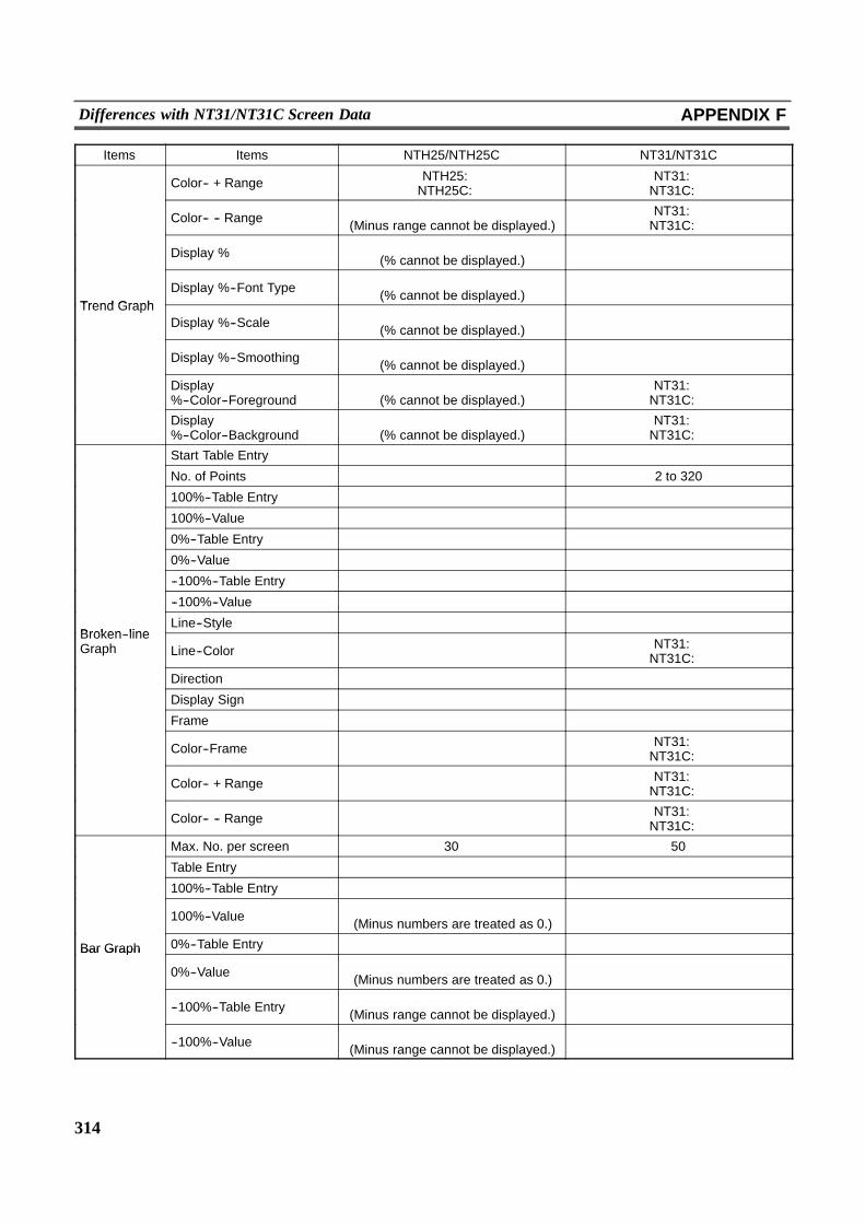
314
Differences with NT31/NT31C Screen Data APPENDIX F
Items Items NTH25/NTH25C NT31/NT31C
Color-- + Range NTH25: �NTH25C: �
NT31: �NT31C: �
Color-- -- Range �(Minus range cannot be displayed.)
NT31: �NT31C: �
Display % �(% cannot be displayed.) �
Trend GraphDisplay %--Font Type �
(% cannot be displayed.) �Trend Graph
Display %--Scale �(% cannot be displayed.) �
Display %--Smoothing �(% cannot be displayed.) �
Display%--Color--Foreground
�(% cannot be displayed.)
NT31: �NT31C: �
Display%--Color--Background
�(% cannot be displayed.)
NT31: �NT31C: �
Start Table Entry � �
No. of Points � 2 to 320
100%--Table Entry � �
100%--Value � �
0%--Table Entry � �
0%--Value � �
--100%--Table Entry � �
--100%--Value � �
Broken lineLine--Style � �
Broken--lineGraph Line--Color � NT31: �
NT31C: �
Direction � �
Display Sign � �
Frame � �
Color--Frame � NT31: �NT31C: �
Color-- + Range � NT31: �NT31C: �
Color-- -- Range � NT31: �NT31C: �
Max. No. per screen 30 50
Table Entry � �
100%--Table Entry � �
100%--Value �(Minus numbers are treated as 0.) �
Bar Graph 0%--Table Entry � �Bar Graph
0%--Value �(Minus numbers are treated as 0.) �
--100%--Table Entry �(Minus range cannot be displayed.) �
--100%--Value �(Minus range cannot be displayed.) �
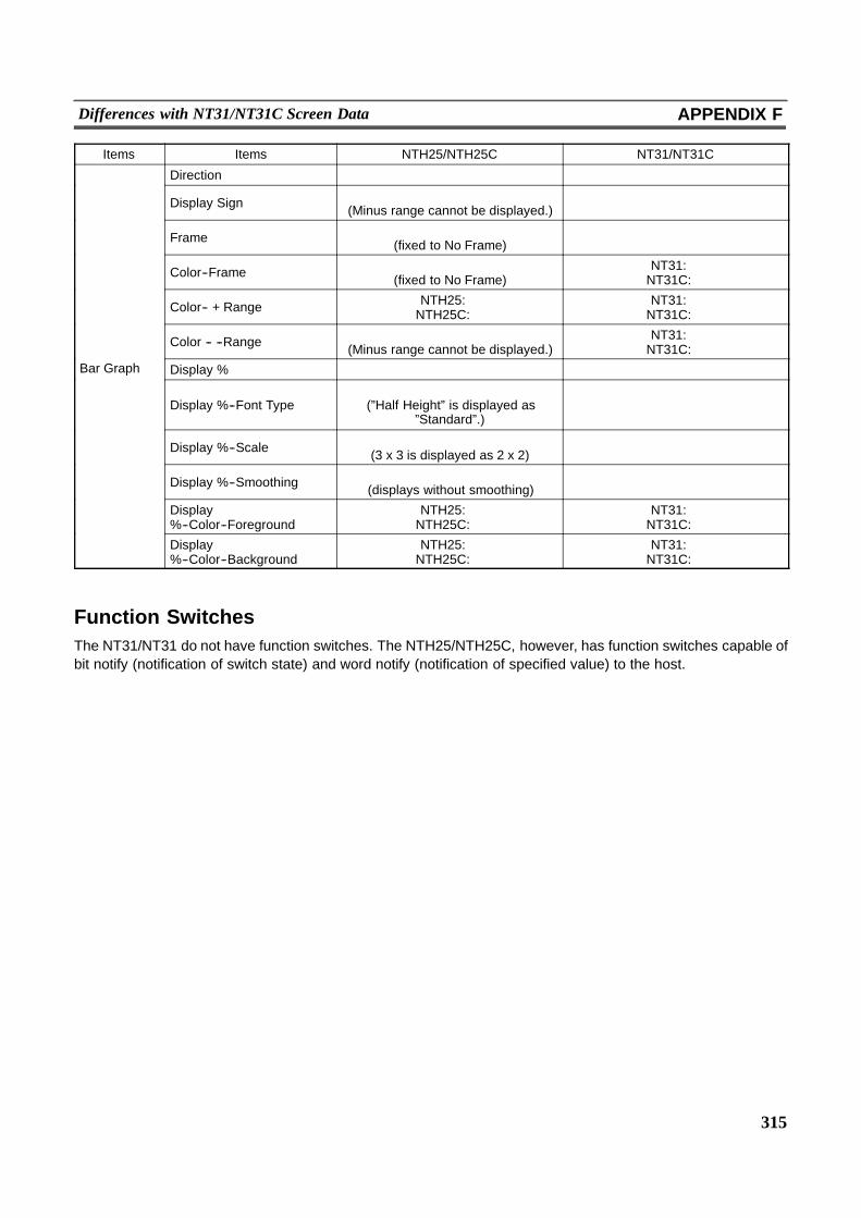
315
Differences with NT31/NT31C Screen Data APPENDIX F
Items Items NTH25/NTH25C NT31/NT31C
Direction � �
Display Sign �(Minus range cannot be displayed.) �
Frame �(fixed to No Frame) �
Color--Frame �(fixed to No Frame)
NT31: �NT31C: �
Color-- + Range NTH25: �NTH25C: �
NT31: �NT31C: �
Color -- --Range �(Minus range cannot be displayed.)
NT31: �NT31C: �
Bar Graph Display % � �p
Display %--Font Type�
(”Half Height” is displayed as”Standard”.)
�
Display %--Scale �(3 x 3 is displayed as 2 x 2) �
Display %--Smoothing �(displays without smoothing) �
Display%--Color--Foreground
NTH25: �NTH25C: �
NT31: �NT31C: �
Display%--Color--Background
NTH25: �NTH25C: �
NT31: �NT31C: �
Function SwitchesThe NT31/NT31 do not have function switches. The NTH25/NTH25C, however, has function switches capable ofbit notify (notification of switch state) and word notify (notification of specified value) to the host.
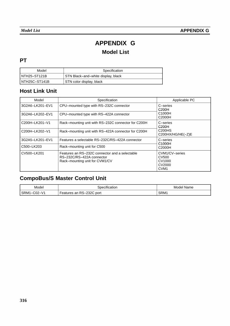
316
Model List APPENDIX G
APPENDIX GModel List
PT
Model Specification
NTH25--ST121B STN Black--and--white display, black
NTH25C--ST141B STN color display, black
Host Link Unit
Model Specification Applicable PC
3G2A6--LK201--EV1 CPU--mounted type with RS--232C connector C--seriesC200H
3G2A6--LK202--EV1 CPU--mounted type with RS--422A connectorC200HC1000HC2000H
C200H--LK201--V1 Rack--mounting unit with RS--232C connector for C200H C--seriesC200H
C200H--LK202--V1 Rack--mounting unit with RS--422A connector for C200HC200HC200HSC200HX/HG/HE(--Z)E
3G2A5--LK201--EV1 Features a selectable RS--232C/RS--422A connector C--seriesC1000H
C500--LK203 Rack--mounting unit for C500C1000HC2000H
CV500--LK201 Features an RS--232C connector and a selectableRS--232C/RS--422A connectorRack--mounting unit for CVM1/CV
CVM1/CV--seriesCV500CV1000CV2000CVM1
CompoBus/S Master Control Unit
Model Specification Model Name
SRM1--C02--V1 Features an RS--232C port SRM1
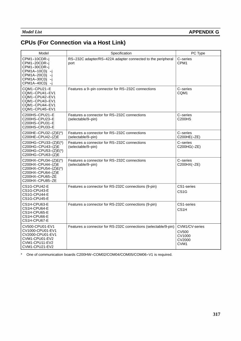
317
Model List APPENDIX G
CPUs (For Connection via a Host Link)
Model Specification PC Type
CPM1--10CDR--jCPM1--20CDR--jCPM1--30CDR--jCPM1A--10CDj--jCPM1A--20CDj--jCPM1A--30CDj--jCPM1A--40CDj--j
RS--232C adapter/RS--422A adapter connected to the peripheralport
C--seriesCPM1
CQM1--CPU21--ECQM1--CPU41--EV1CQM1--CPU42--EV1CQM1--CPU43--EV1CQM1--CPU44--EV1CQM1--CPU45--EV1
Features a 9--pin connector for RS--232C connections C--seriesCQM1
C200HS--CPU21--EC200HS--CPU23--EC200HS--CPU31--EC200HS--CPU33--E
Features a connector for RS--232C connections(selectable/9--pin)
C--seriesC200HS
C200HE--CPU32--(Z)E(*)C200HE--CPU42--(Z)E
Features a connector for RS--232C connections(selectable/9--pin)
C--seriesC200HE(--ZE)
C200HG--CPU33--(Z)E(*)C200HG--CPU43--(Z)EC200HG--CPU53--(Z)E(*)C200HG--CPU63--(Z)E
Features a connector for RS--232C connections(selectable/9--pin)
C--seriesC200HG(--ZE)
C200HX--CPU34--(Z)E(*)C200HX--CPU44--(Z)EC200HX--CPU54--(Z)E(*)C200HX--CPU64--(Z)EC200HX--CPU65--ZEC200HX--CPU85--ZE
Features a connector for RS--232C connections(selectable/9--pin)
C--seriesC200HX(--ZE)
CS1G-CPU42-ECS1G-CPU43-ECS1G-CPU44-ECS1G-CPU45-E
Features a connector for RS-232C connections (9-pin) CS1-seriesCS1G
CS1H-CPU63-ECS1H-CPU64-ECS1H-CPU65-ECS1H-CPU66-ECS1H-CPU67-E
Features a connector for RS-232C connections (9-pin) CS1-seriesCS1H
CV500-CPU01-EV1CV1000-CPU01-EV1CV2000-CPU01-EV1CVM1-CPU01-EV2CVM1-CPU11-EV2CVM1-CPU21-EV2
Features a connector for RS-232C connections (selectable/9-pin) CVM1/CV-seriesCV500CV1000CV2000CVM1
* One of communication boards C200HW--COM02/COM04/COM05/COM06--V1 is required.
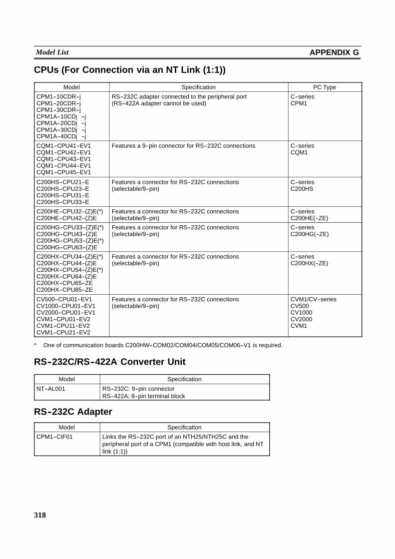
318
Model List APPENDIX G
CPUs (For Connection via an NT Link (1:1))
Model Specification PC Type
CPM1--10CDR--jCPM1--20CDR--jCPM1--30CDR--jCPM1A--10CDj--jCPM1A--20CDj--jCPM1A--30CDj--jCPM1A--40CDj--j
RS--232C adapter connected to the peripheral port(RS--422A adapter cannot be used)
C--seriesCPM1
CQM1--CPU41--EV1CQM1--CPU42--EV1CQM1--CPU43--EV1CQM1--CPU44--EV1CQM1--CPU45--EV1
Features a 9--pin connector for RS--232C connections C--seriesCQM1
C200HS--CPU21--EC200HS--CPU23--EC200HS--CPU31--EC200HS--CPU33--E
Features a connector for RS--232C connections(selectable/9--pin)
C--seriesC200HS
C200HE--CPU32--(Z)E(*)C200HE--CPU42--(Z)E
Features a connector for RS--232C connections(selectable/9--pin)
C--seriesC200HE(--ZE)
C200HG--CPU33--(Z)E(*)C200HG--CPU43--(Z)EC200HG--CPU53--(Z)E(*)C200HG--CPU63--(Z)E
Features a connector for RS--232C connections(selectable/9--pin)
C--seriesC200HG(--ZE)
C200HX--CPU34--(Z)E(*)C200HX--CPU44--(Z)EC200HX--CPU54--(Z)E(*)C200HX--CPU64--(Z)EC200HX--CPU65--ZEC200HX--CPU85--ZE
Features a connector for RS--232C connections(selectable/9--pin)
C--seriesC200HX(--ZE)
CV500--CPU01--EV1CV1000--CPU01--EV1CV2000--CPU01--EV1CVM1--CPU01--EV2CVM1--CPU11--EV2CVM1--CPU21--EV2
Features a connector for RS--232C connections(selectable/9--pin)
CVM1/CV--seriesCV500CV1000CV2000CVM1
* One of communication boards C200HW--COM02/COM04/COM05/COM06--V1 is required.
RS--232C/RS--422A Converter Unit
Model Specification
NT--AL001 RS--232C: 9--pin connectorRS--422A: 8--pin terminal block
RS--232C Adapter
Model Specification
CPM1--CIF01 Links the RS--232C port of an NTH25/NTH25C and theperipheral port of a CPM1 (compatible with host link, and NTlink (1:1))
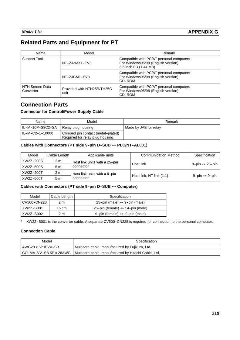
319
Model List APPENDIX G
Related Parts and Equipment for PT
Name Model Remark
Support ToolNT--ZJ3MX1--EV3
Compatible with PC/AT personal computersFor Windows95/98 (English version)3.5 inch FD (1.44 MB)
NT--ZJCM1--EV3Compatible with PC/AT personal computersFor Windows95/98 (English version)CD--ROM
NTH Screen DataConverter Provided with NTH25/NTH25C
unit
Compatible with PC/AT personal computersFor Windows95/98 (English version)CD--ROM
Connection PartsConnector for Control/Power Supply Cable
Name Model Remark
IL--M--10P--S3C2--SA Relay plug housing Made by JAE for relay
IL--M--C2--1--10000 Crimped pin contact (metal--plated)Required for relay plug housing
y y
Cables with Connectors (PT side 9--pin D--SUB $ PLC/NT--AL001)
Model Cable Length Applicable units Communication Method Specification
XW2Z--200S 2 m Host link units with a 25--pin Host link 9 pin$ 25 pinXW2Z--500S 5 m
Host link units with a 25--pinconnector Host link 9--pin$ 25--pin
XW2Z--200T 2 m Host link units with a 9--pin Host link NT link (1:1) 9 pin$ 9 pinXW2Z--500T 5 m
Host link units with a 9--pinconnector Host link, NT link (1:1) 9--pin$ 9--pin
Cables with Connectors (PT side 9--pin D--SUB $ Computer)
Model Cable Length Specification
CV500--CN228 2 m 25--pin (male) $ 9--pin (male)
XW2Z--S001 15 cm 25--pin (female) $ 14--pin (male)
XW2Z--S002 2 m 9--pin (female) $ 9--pin (male)
* XW2Z--S001 is the converter cable. A separate CV500--CN228 is required for connection to the personal computer.
Connection Cable
Model Specification
AWG28 x 5P IFVV--SB Multicore cable, manufactured by Fujikura, Ltd.
CO--MA--VV--SB 5P x 28AWG Multicore cable, manufactured by Hitachi Cable, Ltd.
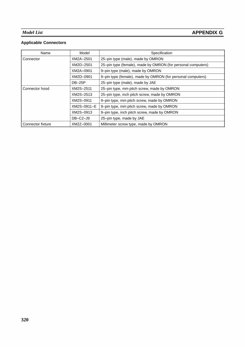
320
Model List APPENDIX G
Applicable Connectors
Name Model Specification
Connector XM2A--2501 25--pin type (male), made by OMRON
XM2D--2501 25--pin type (female), made by OMRON (for personal computers)
XM2A--0901 9--pin type (male), made by OMRON
XM2D--0901 9--pin type (female), made by OMRON (for personal computers)
DB--25P 25--pin type (male), made by JAE
Connector hood XM2S--2511 25--pin type, mm pitch screw, made by OMRON
XM2S--2513 25--pin type, inch pitch screw, made by OMRON
XM2S--0911 9--pin type, mm pitch screw, made by OMRON
XM2S--0911--E 9--pin type, mm pitch screw, made by OMRON
XM2S--0913 9--pin type, inch pitch screw, made by OMRON
DB--C2--J9 25--pin type, made by JAE
Connector fixture XM2Z--0001 Millimeter screw type, made by OMRON
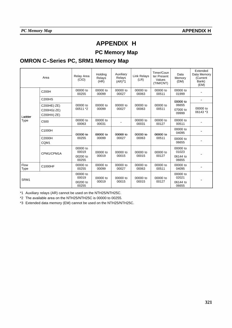
321
PC Memory Map APPENDIX H
APPENDIX HPC Memory Map
OMRON C--Series PC, SRM1 Memory Map
Area Relay Area(CIO)
HoldingRelays(HR)
AuxiliaryRelays(AR)*1
Link Relays(LR)
Timer/Counter PresentValues
(TIM/CNT)
DataMemory(DM)
ExtendedData Memory(CurrentBank)(EM)
C200H 00000 to00255
00000 to00099
00000 to00027
00000 to00063
00000 to00511
00000 to01999 --
C200HS00000 to --
Ladder
C200HE(-ZE)C200HG(-ZE)C200HX(-ZE)
00000 to00511 *2
00000 to00099
00000 to00027
00000 to00063
00000 to00511
00000 to0665507000 to09999
00000 to06143 *3
LadderType C500 00000 to
0006300000 to00031 -- 00000 to
0003100000 to00127
00000 to00511 --
C1000H00000 to 00000 to 00000 to 00000 to 00000 to
00000 to04095 --
C2000HCQM1
00000 to00255
00000 to00099
00000 to00027
00000 to00063
00000 to00511 00000 to
06655 --
CPM1/CPM1A
00000 to0001900200 to00255
00000 to00019
00000 to00015
00000 to00015
00000 to00127
00000 to0102306144 to06655
--
FlowType
C1000HF 00000 to00255
00000 to00099
00000 to00027
00000 to00063
00000 to00511
00000 to04095 --
SRM1
00000 to0001900200 to00255
00000 to00019
00000 to00015
00000 to00015
00000 to00127
00000 to0202106144 to06655
--
*1 Auxiliary relays (AR) cannot be used on the NTH25/NTH25C.*2 The available area on the NTH25/NTH25C is 00000 to 00255.*3 Extended data memory (EM) cannot be used on the NTH25/NTH25C.
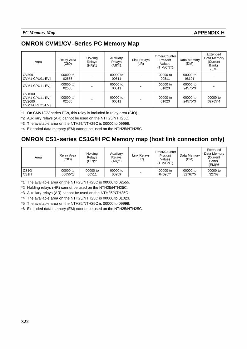
322
PC Memory Map APPENDIX H
OMRON CVM1/CV--Series PC Memory Map
Area Relay Area(CIO)
HoldingRelays(HR)*1
AuxiliaryRelays(AR)*2
Link Relays(LR)
Timer/CounterPresentValues
(TIM/CNT)
Data Memory(DM)
ExtendedData Memory(CurrentBank)(EM)
CV500CVM1-CPU01-EVj
00000 to02555 -- 00000 to
00511 -- 00000 to00511
00000 to08191 --
CVM1-CPU11-EVj 00000 to02555 -- 00000 to
00511 -- 00000 to01023
00000 to24575*3 --
CV1000CVM1-CPU11-EVjCV2000CVM1-CPU21-EVj
00000 to02555 -- 00000 to
00511 -- 00000 to01023
00000 to24575*3
00000 to32765*4
*1 On CMV1/CV series PCs, this relay is included in relay area (CIO).*2 Auxiliary relays (AR) cannot be used on the NTH25/NTH25C.*3 The available area on the NTH25/NTH25C is 00000 to 09999.*4 Extended data memory (EM) cannot be used on the NTH25/NTH25C.
OMRON CS1--series CS1G/H PC Memory map (host link connection only)
Area Relay Area(CIO)
HoldingRelays(HR)*2
AuxiliaryRelays(AR)*3
Link Relays(LR)
Timer/CounterPresentValues
(TIM/CNT)
Data Memory(DM)
ExtendedData Memory(CurrentBank)(EM)*6
CS1GCS1H
00000 to06655*1
00000 to00511
00000 to00959 -- 00000 to
04095*400000 to32767*5
00000 to32767
*1 The available area on the NTH25/NTH25C is 00000 to 02555.*2 Holding relays (HR) cannot be used on the NTH25/NTH25C.*3 Auxiliary relays (AR) cannot be used on the NTH25/NTH25C.*4 The available area on the NTH25/NTH25C is 00000 to 01023.*5 The available area on the NTH25/NTH25C is 00000 to 09999.*6 Extended data memory (EM) cannot be used on the NTH25/NTH25C.
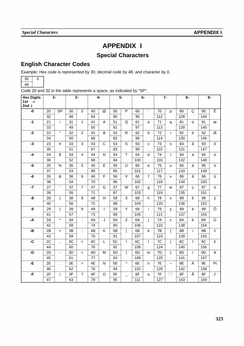
323
Special Characters APPENDIX I
APPENDIX ISpecial Characters
English Character CodesExample: Hex code is represented by 30, decimal code by 48, and character by 0.
30 0
48
Code 20 and 32 in the table represents a space, as indicated by “SP”.
Hex Digits1st2nd
2- 3- 4- 5- 6- 7- 8- 9-
-0 20 SP 30 0 40 @ 50 P 60 ‘ 70 p 80 Ç 90 É32 48 64 80 96 112 128 144
-1 21 ! 31 1 41 A 51 Q 61 a 71 q 81 ü 91 æ33 49 65 81 97 113 129 145
-2 22 ” 32 2 42 B 52 R 62 b 72 r 82 é 92 Æ34 50 66 82 98 114 130 146
-3 23 # 33 3 43 C 53 S 63 c 73 s 83 â 93 ô35 51 67 83 99 115 131 147
-4 24 $ 34 4 44 D 54 T 64 d 74 t 84 ä 94 ö36 52 68 84 100 116 132 148
-5 25 % 35 5 45 E 55 U 65 e 75 u 85 à 95 ò37 53 69 85 101 117 133 149
-6 26 & 36 6 46 F 56 V 66 f 76 v 86 å 96 û38 54 70 86 102 118 134 150
-7 27 ’ 37 7 47 G 57 W 67 g 77 w 87 ç 97 ù39 55 71 87 103 119 135 151
-8 28 ( 38 8 48 H 58 X 68 h 78 x 88 ê 98 ÿ40 56 72 88 104 120 136 152
-9 29 ) 39 9 49 I 59 Y 69 i 79 y 89 ë 99 Ö41 57 73 89 105 121 137 153
-A 2A * 3A : 4A J 5A Z 6A j 7A z 8A è 9A Ü42 58 74 90 106 122 138 154
-B 2B + 3B ; 4B K 5B [ 6B k 7B { 8B ï 9B ¢43 59 75 91 107 123 139 155
-C 2C , 3C < 4C L 5C \ 6C l 7C | 8C î 9C £44 60 76 92 108 124 140 156
-D 2D - 3D = 4D M 5D ] 6D m 7D } 8D ì 9D ¥45 61 77 93 109 125 141 157
-E 2E . 3E > 4E N 5E ^ 6E n 7E ~ 8E Ä 9E Pt46 62 78 94 110 126 142 158
-F 2F / 3F ? 4F O 5F _ 6F o 7F 8F Å 9F ƒ47 63 79 95 111 127 143 159
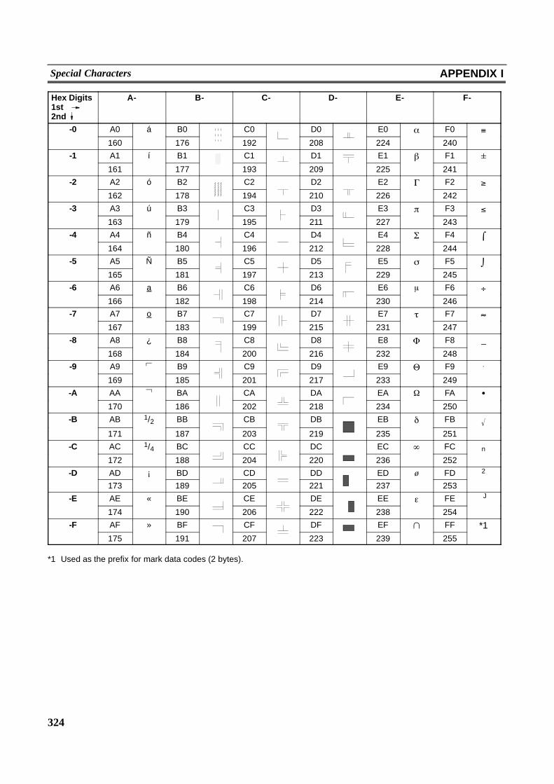
324
Special Characters APPENDIX I
Hex Digits1st2nd
A- B- C- D- E- F-
-0 A0 á B0 C0 D0 E0 # F0 -160 176 192 208 224 240
-1 A1 í B1 C1 D1 E1 . F1 161 177 193 209 225 241
-2 A2 ó B2 C2 D2 E2 / F2 0162 178 194 210 226 242
-3 A3 ú B3 C3 D3 E3 1 F3 2163 179 195 211 227 243
-4 A4 ñ B4 C4 D4 E4 3 F4 4164 180 196 212 228 244
-5 A5 Ñ B5 C5 D5 E5 5 F5 6165 181 197 213 229 245
-6 A6 a B6 C6 D6 E6 μ F6 7166 182 198 214 230 246
-7 A7 o B7 C7 D7 E7 8 F7 9167 183 199 215 231 247
-8 A8 ¿ B8 C8 D8 E8 : F8 _
168 184 200 216 232 248
-9 A9 B9 C9 D9 E9 ; F9 .
169 185 201 217 233 249
-A AA BA CA DA EA , FA !170 186 202 218 234 250
-B AB 1/2 BB CB DB EB < FB 171 187 203 219 235 251
-C AC 1/4 BC CC DC EC = FC n
172 188 204 220 236 252
-D AD ¡ BD CD DD ED ø FD 2
173 189 205 221 237 253
-E AE « BE CE DE EE > FE J
174 190 206 222 238 254
-F AF » BF CF DF EF ? FF *1175 191 207 223 239 255
*1 Used as the prefix for mark data codes (2 bytes).
325
INDEX
NUMBER
9--pin D--SUB connector, Pin arrangement of 37. . .
A
Alarm History 189. . . . . . . . . . . . . . . . . . . . . . . . . . . . .Alarm List 189. . . . . . . . . . . . . . . . . . . . . . . . . . . . . . . .alarm list and alarm history,Differences between 189. . . . . . . . . . . . . . . . . . . . . . .Alarm list/history function (bit memory table) 103. .Allocated Bits and Words, Functions of 17. . . . . . . .Allowable power supply voltage range 286. . . . . . . .Alternate (function switch) 266. . . . . . . . . . . . . . . . . .Alternate (touch switch) 154. . . . . . . . . . . . . . . . . . . .Applicable Connectors 34, 320. . . . . . . . . . . . . . . . .Arc 110. . . . . . . . . . . . . . . . . . . . . . . . . . . . . . . . . . . . . .
B
Background function (trend graph) 184. . . . . . . . . . .Backlight Auto OFF(NTH Screen Data Converter) 262. . . . . . . . . . . . . . .Backlight Auto OFF (configuration) 82. . . . . . . . . . .Backlight OFF Function 215. . . . . . . . . . . . . . . . . . . .Backlight mode (PT status control bit) 93. . . . . . . . .Backlight status (PT status notify bit) 94. . . . . . . . . .Bar Graphs 172. . . . . . . . . . . . . . . . . . . . . . . . . . . . . . .Bar graph (PT memory) 241. . . . . . . . . . . . . . . . . . . .Base display 211. . . . . . . . . . . . . . . . . . . . . . . . . . . . . .Baud rate (NTH Screen Data Converter) 263. . . . .Baud rate (configuration) 82. . . . . . . . . . . . . . . . . . . .BCD 81, 163, 208. . . . . . . . . . . . . . . . . . . . . . . . . . . . .Binary data format 81. . . . . . . . . . . . . . . . . . . . . . . . . .Bit Memory Table 103. . . . . . . . . . . . . . . . . . . . . . . . . .Bit memory table (PT memory) 238. . . . . . . . . . . . . .
C
cable, Making the 300. . . . . . . . . . . . . . . . . . . . . . . . .Cables with connectors 319. . . . . . . . . . . . . . . . . . . .”CANCEL” touch switch (CHECK menu) 64. . . . . . .Cell size (touch panel) 287. . . . . . . . . . . . . . . . . . . . .Character String Display 166. . . . . . . . . . . . . . . . . . .Character String Memory Table 101. . . . . . . . . . . . .character strings (character string display), How tospecify 170. . . . . . . . . . . . . . . . . . . . . . . . . . . . . . . . . . .Character size (character string display) 169. . . . . .Character size and attribute(character string display) 169. . . . . . . . . . . . . . . . . . .Character string display (PT memory) 245. . . . . . . .Character string memory table No.(bit memory table) 104. . . . . . . . . . . . . . . . . . . . . . . . .
CHECK menu 62. . . . . . . . . . . . . . . . . . . . . . . . . . . . . .CHECK menu, Calling the 63. . . . . . . . . . . . . . . . . . .CHECK menu, Operations with the 63. . . . . . . . . . .Circle 111. . . . . . . . . . . . . . . . . . . . . . . . . . . . . . . . . . . .Cleaning method 282. . . . . . . . . . . . . . . . . . . . . . . . . .Clear bit (Trend graph control area) 97. . . . . . . . . . .Clear trend graph record (PT memory) 243. . . . . . .Clock Data, Setting the 71. . . . . . . . . . . . . . . . . . . . . .Clock Setting Mode 62. . . . . . . . . . . . . . . . . . . . . . . . .Clock data (PT memory) 235. . . . . . . . . . . . . . . . . . .Clock data (PT status notify area) 95. . . . . . . . . . . .Clock data output (PT status notify area) 92. . . . . .Clock function 216. . . . . . . . . . . . . . . . . . . . . . . . . . . . .Color Display 85. . . . . . . . . . . . . . . . . . . . . . . . . . . . . .Commands/Responses (memory link) 225. . . . . . . .Comment (Screen attributes) 83. . . . . . . . . . . . . . . .Comments (PT configuration) 80. . . . . . . . . . . . . . . .Communication board 41, 53. . . . . . . . . . . . . . . . . . .Communication page(NTH Screen Data Converter) 262. . . . . . . . . . . . . . .Communications Specifications 291. . . . . . . . . . . . .Communications method 30, 261. . . . . . . . . . . . . . .Communications protocol (memory link) 224. . . . . .Communications type 30. . . . . . . . . . . . . . . . . . . . . . .Compatible Peripheral Devices 24. . . . . . . . . . . . . . .Compatible Peripheral Devices 24. . . . . . . . . . . . . . .CompoBus/S Master Control Unit 316. . . . . . . . . . . .Configuration settings 80. . . . . . . . . . . . . . . . . . . . . . .Configuration settings(NTH Screen Data Converter) 82, 260. . . . . . . . . . .Confirming Communications 68. . . . . . . . . . . . . . . . .Connecting to the Host 40. . . . . . . . . . . . . . . . . . . . . .Connection Cable 319. . . . . . . . . . . . . . . . . . . . . . . . .Connection method 30. . . . . . . . . . . . . . . . . . . . . . . . .Connections 56. . . . . . . . . . . . . . . . . . . . . . . . . . . . . . .Connector cable, Preparing the 34. . . . . . . . . . . . . . .Connector for Control/Power Supply Cable 319. . .Contrast adjustment 287. . . . . . . . . . . . . . . . . . . . . . .Control code input function (touch switch) 156. . . . .Control key 156. . . . . . . . . . . . . . . . . . . . . . . . . . . . . . .Control key function (touch switch) 147. . . . . . . . . . .control/power supply connector,Connecting the 34. . . . . . . . . . . . . . . . . . . . . . . . . . . . .Control/power supply connector pinarrangement 34. . . . . . . . . . . . . . . . . . . . . . . . . . . . . . .CPU unit 41, 53, 317. . . . . . . . . . . . . . . . . . . . . . . . . .Cursor move touch switch 202. . . . . . . . . . . . . . . . . .
D
Data length (NTH Screen Data Converter) 263. . . .Data length (configuration) 82. . . . . . . . . . . . . . . . . . .
326
Data logging function (trend graph) 184. . . . . . . . . .”DATA TRANSMIT” touch switch(CHECK menu) 65. . . . . . . . . . . . . . . . . . . . . . . . . . . .Data write command (memory link) 225. . . . . . . . . .Date 72. . . . . . . . . . . . . . . . . . . . . . . . . . . . . . . . . . . . . .Default (character string memory table) 102. . . . . .Dielectric strength 286. . . . . . . . . . . . . . . . . . . . . . . . .Dimensions 286, 292. . . . . . . . . . . . . . . . . . . . . . . . . .Direct Connection Function 15. . . . . . . . . . . . . . . . . .Display 33. . . . . . . . . . . . . . . . . . . . . . . . . . . . . . . . . . . .Display Elements Specifications 290. . . . . . . . . . . . .Display Language, Switching the 69. . . . . . . . . . . . .Display Specifications 287. . . . . . . . . . . . . . . . . . . . . .Display Specifications 289. . . . . . . . . . . . . . . . . . . . . .Display color specifications 287. . . . . . . . . . . . . . . . .Display device 287. . . . . . . . . . . . . . . . . . . . . . . . . . . .Display elements table 88. . . . . . . . . . . . . . . . . . . . . .”DISPLAY MONITOR” touch switch(CHECK menu) 73. . . . . . . . . . . . . . . . . . . . . . . . . . . .Display screen (PT status control area) 91. . . . . . . .Display screen number (PT memory) 236. . . . . . . .Display type 163, 208. . . . . . . . . . . . . . . . . . . . . . . . .dots, Number of 287. . . . . . . . . . . . . . . . . . . . . . . . . . .Double--width character, Size of 287. . . . . . . . . . . . .
E
Effective display area 287. . . . . . . . . . . . . . . . . . . . . .emergency stop output, Use of 36. . . . . . . . . . . . . . .Emergency stop switch 33, 36. . . . . . . . . . . . . . . . . .English Character Codes 323. . . . . . . . . . . . . . . . . . .”English” touch switch (CHECK menu) 69. . . . . . . .External Interface Specifications 288. . . . . . . . . . . . .
F
Function Switches, Position Codes of 269. . . . . . . .Function key settings(NTH Screen Data Converter) 265. . . . . . . . . . . . . . .Function switches 33, 214. . . . . . . . . . . . . . . . . . . . .Functional grounding 37. . . . . . . . . . . . . . . . . . . . . . . .
G
General Specifications 286. . . . . . . . . . . . . . . . . . . . .Grounding 37. . . . . . . . . . . . . . . . . . . . . . . . . . . . . . . . .
H
Hand strap 33. . . . . . . . . . . . . . . . . . . . . . . . . . . . . . . .Hardware (NTH Screen Data Converter) 252. . . . . .Hardware switch output 4. . . . . . . . . . . . . . . . . . . . . .Host Link 16. . . . . . . . . . . . . . . . . . . . . . . . . . . . . . . . . .Host Types and Settings 40. . . . . . . . . . . . . . . . . . . .Host link unit 41, 316. . . . . . . . . . . . . . . . . . . . . . . . . .Host notification function (touch switch) 146. . . . . .
Host notification function (touch switch) 153. . . . . .”H” touch switch (CHECK menu) 70. . . . . . . . . . . . .
I
I/O comment (bit memory table) 103. . . . . . . . . . . . .I/O comment (character string memory table) 101.I/O comment (numeral memory table) 98. . . . . . . . .Image Data Display 130. . . . . . . . . . . . . . . . . . . . . . . .image data, Procedure for creating and using 130.Image/library lamps 137. . . . . . . . . . . . . . . . . . . . . . . .Image/library lamps (PT memory) 240. . . . . . . . . . .Initial Processing 61. . . . . . . . . . . . . . . . . . . . . . . . . . .Initial screen (PT configuration) 81. . . . . . . . . . . . . .Initialize page (NTH Screen Data Converter) 261. .input field when there are multiple input fields,Specifying the 202. . . . . . . . . . . . . . . . . . . . . . . . . . . . .Input numeral and stored data 200, 208. . . . . . . . .Inspection method 282. . . . . . . . . . . . . . . . . . . . . . . . .Installation environment 32. . . . . . . . . . . . . . . . . . . . .Inverse color 85. . . . . . . . . . . . . . . . . . . . . . . . . . . . . . .
L
Lamps 137. . . . . . . . . . . . . . . . . . . . . . . . . . . . . . . . . . .LCD Contrast, Adjusting 70. . . . . . . . . . . . . . . . . . . . .Library Data Display 134. . . . . . . . . . . . . . . . . . . . . . .library data display, Procedure for creatingand using 134. . . . . . . . . . . . . . . . . . . . . . . . . . . . . . . .Life expectancy (backlight) 287. . . . . . . . . . . . . . . . .Life expectancy (display panel) 287. . . . . . . . . . . . . .Life expectancy (touch panel) 287. . . . . . . . . . . . . . .”L” touch switch (CHECK menu) 70. . . . . . . . . . . . . .
M
Maintenance 281. . . . . . . . . . . . . . . . . . . . . . . . . . . . . .manual 26. . . . . . . . . . . . . . . . . . . . . . . . . . . . . . . . . . . .Marks 126. . . . . . . . . . . . . . . . . . . . . . . . . . . . . . . . . . . .marks, Procedure for creating and using 126. . . . . .Memory Link, Communications by Using 22. . . . . .Memory Link, Operation of 220. . . . . . . . . . . . . . . . . .Memory Tables 98. . . . . . . . . . . . . . . . . . . . . . . . . . . . .Memory link 55, 57. . . . . . . . . . . . . . . . . . . . . . . . . . .Menu Items, Selecting 64. . . . . . . . . . . . . . . . . . . . . .Message display color (bit memory table) 105. . . . .Model (NTH Screen Data Converter) 261. . . . . . . . .Model (configuration) 82. . . . . . . . . . . . . . . . . . . . . . .Modes, Relationships among 62. . . . . . . . . . . . . . . .Momentary (function switch) 266. . . . . . . . . . . . . . . .Momentary (touch switch) 146. . . . . . . . . . . . . . . . . .mmi format 250. . . . . . . . . . . . . . . . . . . . . . . . . . . . . . .”M” touch switch (CHECK menu) 70. . . . . . . . . . . . .
327
N
Noise resistance 286. . . . . . . . . . . . . . . . . . . . . . . . . .Normal (standard) lamps 137. . . . . . . . . . . . . . . . . . .Normal (standard) screens 83. . . . . . . . . . . . . . . . . .Notify command (memory link) 227. . . . . . . . . . . . . .NT Link 16. . . . . . . . . . . . . . . . . . . . . . . . . . . . . . . . . . .NT link (1:1), When using the 53, 56. . . . . . . . . . . .NT31/NT31C 6. . . . . . . . . . . . . . . . . . . . . . . . . . . . . . .NT31/NT31C Screen Data, Difference with 303. . .NTC Screen Data Converter, How to Install 253. . .NTH Screen Data Converter 24, 259, 319. . . . . . . .NTH Screen Data Converter, Equipment Needed ToUse 252. . . . . . . . . . . . . . . . . . . . . . . . . . . . . . . . . . . . .NTH Screen Data Converter, Exiting 260. . . . . . . . .NTH Screen Data Converter, Setting Up 252. . . . . .NTH Screen Data Converter, Starting up 259. . . . .NTH Screen Data Converter?, What is 250. . . . . . .NTH protocol 22. . . . . . . . . . . . . . . . . . . . . . . . . . . . . .NTH25 and NTH25C, Comparison between 5. . . . .NTH25/NTH25C and NT31/NT31C, Comparisonbetween 6. . . . . . . . . . . . . . . . . . . . . . . . . . . . . . . . . . . .NTH25/NTH25C for the first time, When usingthe 60. . . . . . . . . . . . . . . . . . . . . . . . . . . . . . . . . . . . . . .NTH25/NTH25C, Before operating the 26. . . . . . . .NTH25/NTH25C, Principal Functions of 8. . . . . . . .NTH25/NTH25C, Starting the 61. . . . . . . . . . . . . . . .NTH25/NTH25C, Transporting andStoring the 299. . . . . . . . . . . . . . . . . . . . . . . . . . . . . . .Numeral Display 159. . . . . . . . . . . . . . . . . . . . . . . . . .Numeral Memory Tables 98. . . . . . . . . . . . . . . . . . . .Numeral Storage Type 163, 208. . . . . . . . . . . . . . . .Numeral Storage Type (PT configuration) 81. . . . . .Numeral display (PT memory) 239. . . . . . . . . . . . . . .Numeral input 196. . . . . . . . . . . . . . . . . . . . . . . . . . . . .Numeral input (PT memory) 233. . . . . . . . . . . . . . . .Numeral input strobe (PT status notify bits) 94. . . .Numerals and contents of host words 201. . . . . . . .Numerical key type (numeral input) 196. . . . . . . . . .
O
Operating ambient humidity 286. . . . . . . . . . . . . . . . .Operating ambient temperature 286. . . . . . . . . . . . .Operating environment 286. . . . . . . . . . . . . . . . . . . . .Operating force (touch panel) 287. . . . . . . . . . . . . .Operating system (NTH Screen DataConverter) 252. . . . . . . . . . . . . . . . . . . . . . . . . . . . . . . .Operation Modes 62. . . . . . . . . . . . . . . . . . . . . . . . . . .Operation Modes 62. . . . . . . . . . . . . . . . . . . . . . . . . . .Operation at Startup 61. . . . . . . . . . . . . . . . . . . . . . . .operation output, Use of 36. . . . . . . . . . . . . . . . . . . . .operation, Starting 67. . . . . . . . . . . . . . . . . . . . . . . . . .Operation switch output 36. . . . . . . . . . . . . . . . . . . . .Operation switches 33. . . . . . . . . . . . . . . . . . . . . . . . .
P
Panel Specifications 287. . . . . . . . . . . . . . . . . . . . . . .Parity (NTH Screen Data Converter) 263. . . . . . . . .Parity (configuration) 82. . . . . . . . . . . . . . . . . . . . . . . .Pen recorder type (trend graph) 182. . . . . . . . . . . . .Permissible Display Range 164. . . . . . . . . . . . . . . . .Permissible input ranges 208. . . . . . . . . . . . . . . . . . .PLC Address (bit memory table) 106. . . . . . . . . . . . .PLC Address (character string memory table) 102.PLC Address (numeral memory table) 99. . . . . . . . .PLC Memory Map 321. . . . . . . . . . . . . . . . . . . . . . . . .PLC setting (NTH Screen Data Converter) 263. . . .PLC settings (configuration) 260. . . . . . . . . . . . . . . .Pin arrangement 34, 37. . . . . . . . . . . . . . . . . . . . . . .Polygon 114. . . . . . . . . . . . . . . . . . . . . . . . . . . . . . . . . .Polyline 116. . . . . . . . . . . . . . . . . . . . . . . . . . . . . . . . . .Pop--up window/keyboard function(touch switch) 157. . . . . . . . . . . . . . . . . . . . . . . . . . . . .Power consumption 286. . . . . . . . . . . . . . . . . . . . . . . .Power supply connection 35. . . . . . . . . . . . . . . . . . . .Power supply specifications 35. . . . . . . . . . . . . . . . . .”PROG. CONSOLE” touch switch(CHECK menu) 74. . . . . . . . . . . . . . . . . . . . . . . . . . . .Programming Console Mode 62. . . . . . . . . . . . . . . . .Programming console function 74, 84, 217. . . . . . .Programming environment 288. . . . . . . . . . . . . . . . . .PT 316. . . . . . . . . . . . . . . . . . . . . . . . . . . . . . . . . . . . . .PT Configuration Settings (support tool) 80. . . . . . .PT Control/Notify Area (PT configuration) 80. . . . . .PT Memory, Configuration of 221. . . . . . . . . . . . . . . .PT Model (PT configuration) 80. . . . . . . . . . . . . . . . .PT Status Control Area 90. . . . . . . . . . . . . . . . . . . . .PT Status Notify Area 93. . . . . . . . . . . . . . . . . . . . . . .PT memory 22, 220. . . . . . . . . . . . . . . . . . . . . . . . . . .PT status control bit (PT memory) 237. . . . . . . . . . .PT status control bit (PT status control area) 92. . .PT status notify bit (PT memory) 234. . . . . . . . . . . .PT status notify bits (PT status notify area) 94. . . .Push--lock switch 33, 36. . . . . . . . . . . . . . . . . . . . . . .
R
Rated power supply voltage 286. . . . . . . . . . . . . . . . .Read command (memory link) 226. . . . . . . . . . . . . .Rectangle 113. . . . . . . . . . . . . . . . . . . . . . . . . . . . . . . .registered screens (touch panel),Max. number of 289. . . . . . . . . . . . . . . . . . . . . . . . . . .Resolution 287. . . . . . . . . . . . . . . . . . . . . . . . . . . . . . . .RS--232C Adapter 318. . . . . . . . . . . . . . . . . . . . . . . . .RS--232C/RS--422A Converter Unit 318. . . . . . . . . .RS--232C/RS--422A Converter Unit, Using an 293.RUN Mode, Switching to the 64, 67. . . . . . . . . . . . .
328
S
Sampling stop/continue bit (trend graph controlarea) 97. . . . . . . . . . . . . . . . . . . . . . . . . . . . . . . . . . . . .Screen Attributes 85. . . . . . . . . . . . . . . . . . . . . . . . . . .Screen Composition 83. . . . . . . . . . . . . . . . . . . . . . . .Screen Data (NTH Screen Data Converter),Transmitting 273. . . . . . . . . . . . . . . . . . . . . . . . . . . . . .Screen Data Converter, Connecting to theNTH 38. . . . . . . . . . . . . . . . . . . . . . . . . . . . . . . . . . . . . .Screen Data, Checking 73. . . . . . . . . . . . . . . . . . . . . .Screen Data, Precautions to Be Observed WhenTransmitting 66. . . . . . . . . . . . . . . . . . . . . . . . . . . . . . .Screen Data, Transmitting the 65. . . . . . . . . . . . . . . .Screen Monitor Mode 62. . . . . . . . . . . . . . . . . . . . . . .Screen Numbers 83. . . . . . . . . . . . . . . . . . . . . . . . . . .Screen Transmit Mode 62. . . . . . . . . . . . . . . . . . . . . .Screen Types 83. . . . . . . . . . . . . . . . . . . . . . . . . . . . . .Screen switching function (touch switch) 146, 155.Sector 117. . . . . . . . . . . . . . . . . . . . . . . . . . . . . . . . . . .Serial port 30. . . . . . . . . . . . . . . . . . . . . . . . . . . . . . . . .”SET UP TIME” touch switch (CHECK menu) 71. .SET UP touch switch (initial screen) 63. . . . . . . . . .”SET UP” touch switch (initial screen) 63. . . . . . . . .SETUP (NTH Screen Data Converter) 254. . . . . . .Special Features 290. . . . . . . . . . . . . . . . . . . . . . . . . .Specified value (function switch) 268. . . . . . . . . . . . .Standard (trend graph) 176. . . . . . . . . . . . . . . . . . . . .Standard lamp (PT memory) 247. . . . . . . . . . . . . . . .Stop bit (NTH Screen Data Converter) 263. . . . . . .Stop bit (configuration) 82. . . . . . . . . . . . . . . . . . . . . .Storage Type (numeral memory table) 99. . . . . . . .Storage Type and Recognizable Numerals 81. . . . .Storage ambient temperature 286. . . . . . . . . . . . . . .Support Tool 24, 319. . . . . . . . . . . . . . . . . . . . . . . . . .Support Tool settings, Differences in the 303. . . . . .switches (function switch), Number of 287. . . . . . . .switches (push lock switch), Number of 287. . . . . . .switches (touch panel), Number of 287. . . . . . . . . . .System Configuration 24. . . . . . . . . . . . . . . . . . . . . . .System screens 84. . . . . . . . . . . . . . . . . . . . . . . . . . . .
T
Temporary Input Fields 214. . . . . . . . . . . . . . . . . . . . .Text (Fixed Display) 119. . . . . . . . . . . . . . . . . . . . . . . .Thumbwheel type (numeric input) 203. . . . . . . . . . . .Tiling 123. . . . . . . . . . . . . . . . . . . . . . . . . . . . . . . . . . . .Time 71. . . . . . . . . . . . . . . . . . . . . . . . . . . . . . . . . . . . . .Touch Switches 145. . . . . . . . . . . . . . . . . . . . . . . . . . .Touch switches, function switches(PT memory) 230. . . . . . . . . . . . . . . . . . . . . . . . . . . . .Transparent display 86. . . . . . . . . . . . . . . . . . . . . . . . .Trend Graph Control Area 96, 186. . . . . . . . . . . . . .Trend Graphs 176. . . . . . . . . . . . . . . . . . . . . . . . . . . . .
Trend graph (PT memory) 242. . . . . . . . . . . . . . . . . .Trend graph control area settings (NTH ScreenData Converter) 271. . . . . . . . . . . . . . . . . . . . . . . . . . .Trend graph sampling stop/continue(PT memory) 244. . . . . . . . . . . . . . . . . . . . . . . . . . . . .Troubleshooting 276. . . . . . . . . . . . . . . . . . . . . . . . . . .Type setting (configuration) 84. . . . . . . . . . . . . . . . . .
U
Uninstall 258. . . . . . . . . . . . . . . . . . . . . . . . . . . . . . . . .Upper/lower (max./min.) limit check 202, 209. . . . .Usable Systems 74. . . . . . . . . . . . . . . . . . . . . . . . . . . .
V
Vibration resistance 286. . . . . . . . . . . . . . . . . . . . . . . .View angle 287. . . . . . . . . . . . . . . . . . . . . . . . . . . . . . .
W
Waterproofing 4. . . . . . . . . . . . . . . . . . . . . . . . . . . . . . .Weight 286. . . . . . . . . . . . . . . . . . . . . . . . . . . . . . . . . . .Window Control Area 95. . . . . . . . . . . . . . . . . . . . . . .Window Function 211. . . . . . . . . . . . . . . . . . . . . . . . . .Window Screens 84. . . . . . . . . . . . . . . . . . . . . . . . . . .Window Screens and Display Elements 212. . . . . .Window control address settings (NTH Screen DataConverter) 269. . . . . . . . . . . . . . . . . . . . . . . . . . . . . . . .Window key 157. . . . . . . . . . . . . . . . . . . . . . . . . . . . . .Window key function 147. . . . . . . . . . . . . . . . . . . . . . .window, Opening/closing a 212. . . . . . . . . . . . . . . . . .Wiring 56. . . . . . . . . . . . . . . . . . . . . . . . . . . . . . . . . . . .Wiring cable 34. . . . . . . . . . . . . . . . . . . . . . . . . . . . . . .Word contents and displayed numeral 163. . . . . . . .Word contents and displayed numeral 163. . . . . . . .
Z
Zero suppression 163. . . . . . . . . . . . . . . . . . . . . . . . . .
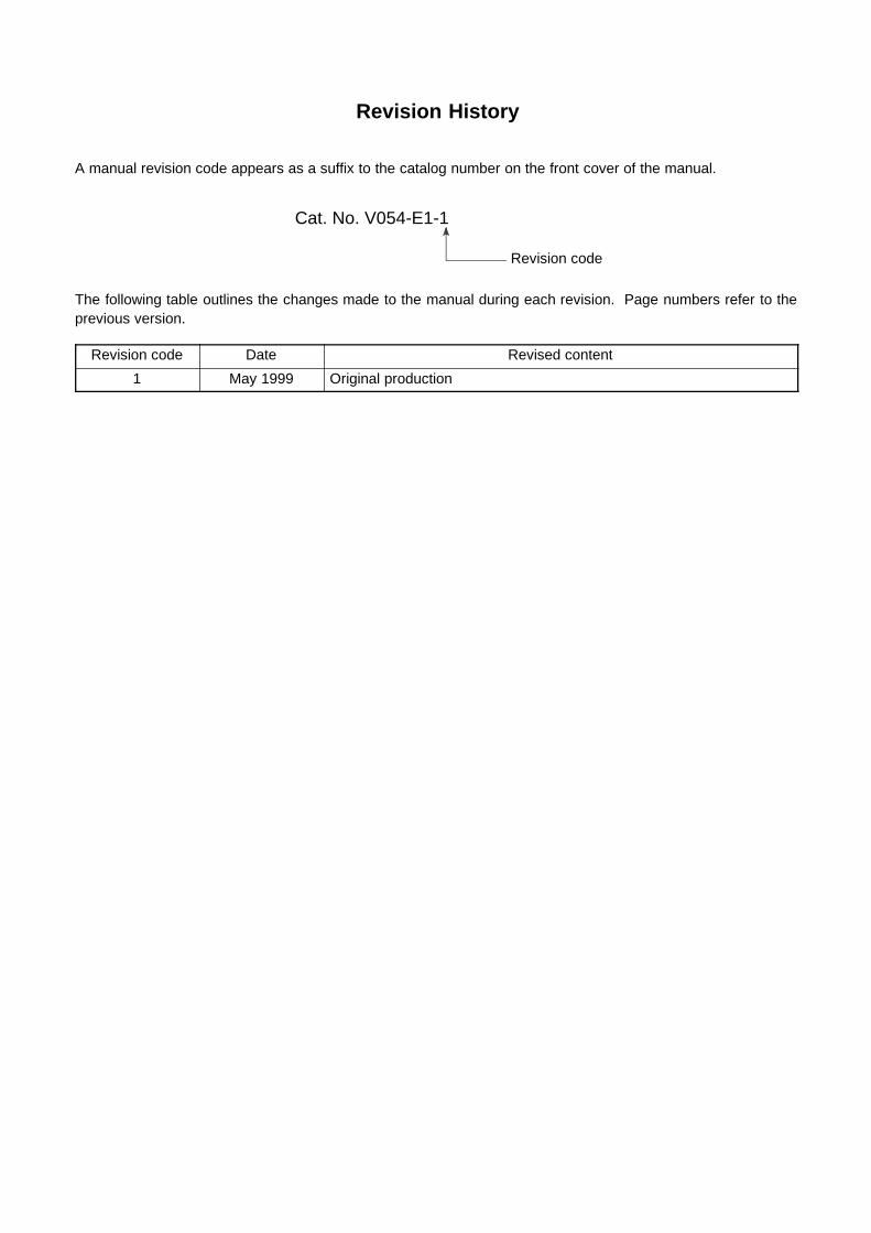
Revision History
A manual revision code appears as a suffix to the catalog number on the front cover of the manual.
Cat. No. V054-E1-1
Revision code
The following table outlines the changes made to the manual during each revision. Page numbers refer to theprevious version.
Revision code Date Revised content
1 May 1999 Original production

9650Corrections InsertManual: NTH25/25C Programmable Terminal Operation ManualCatalog No.: V054--E1--1Date: June 1999
This corrections insert lists corrections made to this manual since it was printed.Only corrections that affect the proper and efficient operation of the device arelisted; minor changes, such as those in spelling and syntax, have been omitted.
Please mark your manuals so that the corrections are noted on the pages concerned, and then securely add anyrequired pages from the Corrections Insert to the rear of the manual.
7--1 Troubleshooting
The error message that is actually displayed may differ from the error message indicated in the Symptoms columnin 7--1 Troubleshooting.
Incorrect Correct
276P The ”Data Communications Error” message isdisplayed.
The ”ERROR” message is displayed.
277P When an attempt is made to enter the RUNmode, the initial screen and the ”No Reply fromHost” message are displayed alternately.
When an attempt is made to enter the RUNmode, the initial screen and the ”No Responsefrom PLC” message are displayed alternately.
The ”Device Setup Error” is displayed. The ”CPU type Error” is displayed.
278P Cannot communicate with the host Example)-- The ”No Reply from Host” message is dis-played.-- Communications error message is displayedduring communications with the host.
Cannot communicate with the host Example)-- The ”No Response from PLC” message isdisplayed.-- Communications error message is displayedduring communications with the host.
The ”No Reply from Host” message is dis-played from time to time during normal opera-tion.
The ”No Response from PLC” message is dis-played from time to time during normal opera-tion.
279P The ”Date Communications Error” message isdisplayed.
The ”Error” message is displayed.
The ”Device Setup Error” is displayed. The ”CPU type Error” is displayed.
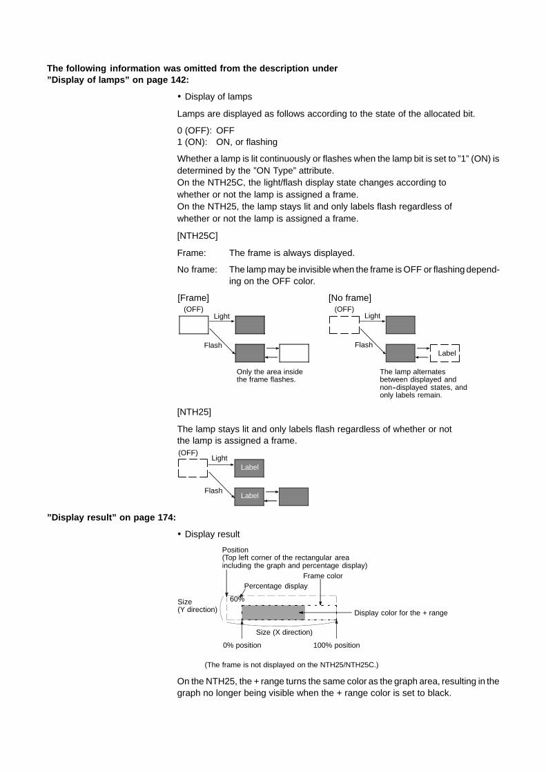
The following information was omitted from the description under”Display of lamps” on page 142:
! Display of lamps
Lamps are displayed as follows according to the state of the allocated bit.
0 (OFF): OFF1 (ON): ON, or flashing
Whether a lamp is lit continuously or flashes when the lamp bit is set to ”1” (ON) isdetermined by the ”ON Type” attribute.On the NTH25C, the light/flash display state changes according towhether or not the lamp is assigned a frame.On the NTH25, the lamp stays lit and only labels flash regardless ofwhether or not the lamp is assigned a frame.
[NTH25C]
Frame: The frame is always displayed.
No frame: The lampmay be invisiblewhen the frame isOFF or flashingdepend-ing on the OFF color.
[Frame] [No frame](OFF)
Light
Flash
Only the area insidethe frame flashes.
(OFF)
The lamp alternatesbetween displayed andnon--displayed states, andonly labels remain.
Light
FlashLabel
[NTH25]
The lamp stays lit and only labels flash regardless of whether or notthe lamp is assigned a frame.(OFF)
Light
Flash
Label
Label
”Display result” on page 174:
! Display result
60%
100% position
Position(Top left corner of the rectangular areaincluding the graph and percentage display)
Percentage display
Display color for the + range
Frame color
Size(Y direction)
0% position
Size (X direction)
(The frame is not displayed on the NTH25/NTH25C.)
On the NTH25, the + range turns the same color as the graph area, resulting in thegraph no longer being visible when the + range color is set to black.