ntrs.nasa.gov · developed pdcr based gage suggested that the gage factor and the ......
TRANSCRIPT
NASA Contractor Report 194441
High Temperature Strain Measurement With a Resistance Strain Gage
Jih-Fen Lei Sverdrup Technology, Inc. Lewis Research Center Group Brook Park, Ohio
and
Ed Fichtel and Amos McDaniel Pratt & Whitney - GESP West Palm Beach, Florida
Prepared for Lewis Research Center Under Contract NAS3-25266
NI\S/\ National Aeronautics and Space Administration
- -- <- --
I I ~
https://ntrs.nasa.gov/search.jsp?R=19940014841 2018-07-08T06:46:01+00:00Z
ABSTRACT
HIGH TEMPERATURE STRAIN MEASUREMENT WITH A RESISTANCE STRAIN GAGE
How to successfully obtain data from a PdCr strain sen-sor
Jih-Fen Lei Sverdrup Technology, Inc.
Lewis Research Center Group Brook Park, Ohio 44142
Ed Fichtel and Amos McDaniel Pratt & Whitney - GESP
West Palm Beach, Florida 33410
A PdCr based electrical resistance strain gage was demonstrated in the laboratory to be a viable sensor candidate for static strain measurement at high temperatures. However, difficulties were encountered while transferring the sensor to field applications. This paper is therefore prepared for recognition and resolution of the problems likely to be encountered with PdCr strain gages in field applications. Errors caused by the measurement system. installation technique and lead wire attachment will be discussed . The limitations and some considerations related to the temperature compensation technique used for this gage will also be addressed.
INTRODUCTION
A PdCr/Pt dual-element temperature-compensated strain gage was developed at NASA Lewis Research Center to meet the urgent need of measuring static strain at elevated temperatures. In applications such as advanced gas turbine engine and hypersonic vehicle ground tests, a sensor is required to operate at temperatures much higher than the present static strain gage technology can provide. Previous results obtained in the laboratory from this newly developed PdCr based gage suggested that the gage factor and the apparent strain of this gage were not very temperature sensitive. The apparent strain was not only small (within 1200 microstrain, IlS) but also repeatable (within 100 f.Js) between thermal cycles to 1470"F [1]. The apparent strain of this gage can therefore be corrected to within a reasonable error up to this high temperature. The gage was then evaluated and determined by Pratt & Whitney (P&W-GESP) to be the only viable sensor candidate to measure static strain at temperatures up to 1400°F [2]. P&W's room temperature fatigue testing also indicated that this PdCr gage was comparable to the standard dynamic strain gage currently used in gas turbine engine testing. It is therefore a potential candidate for measuring dynamic strain in the turbine environment.
However, difficulties were encountered when transferring the sensor from the laboratory to field applications. The gage's performance obtained in the field was not as good as what was obtained in the laboratory. Successfully obtaining data from this sensor is highly dependent on factors such as the purity of the gage wires, the purity of the installation materials, the quality of the installation technique and the stability of the measurement system. Lack of control in any of these areas could drastically affect the performance of the gage. This paper is therefore prepared to identify and to provide resolution for the problems likely to be encountered with PdCr strain gages. The effects of the causes of errors on the performance of the gage will be discussed. Various components of the gage and the measuring system will be addressed to make the gage more compatible with field applications.
Also, in applications such as the National Aerospace Plane (NASP), it is difficult to perform apparent strain calibration on the actual hardware for an individual gage. The prediction and correction of the apparent strain to within specified accuracy limits are a challenge because the corrections must be based on the results of previous tests
1
__ I
on samples of gages. The estimation of the prediction accuracy for this PdCr gage, and some considerations related to the temperature compensation technique used in this gage which limit the accuracy of this prediction will also be addressed in this paper.
ERRORS ASSOCIATED WITH MATERIAL PURITY AND INSTALLATION TECHNIQUE
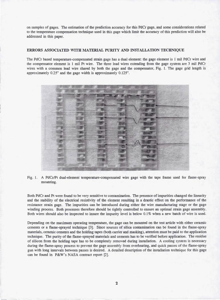
The PdCr based temperature-compensated strain gage has a dual element: the gage element is I mil PdCr wire and the compensator element is I mil Pt wire. The three lead wires extending from the gage system are 3 mil PdCr wires with a common lead wire shared by both the gage and the compensator, Fig. I. The gage grid length is appro!(imately 0.25" and the gage width is approximately 0.125".
Fig. I . A PdCrlPt dual-element temperature-compensated wire gage with the tape frame used for flame-spray mounting.
Both PdCr and Pt were found to be very sensitive to contamination. The presence of impurities changed the linearity and the stability of the electrical resistivity of the element resulting in a drastic effect on the performance of the resistance strain gage. The impurities can be introduced during either the wire manufacturing stage or the gage winding process. Both processes therefore should be tightly controlled to ensure an optimal strain gage assembly. Both wires should also be inspected to insure the impurity level is below 0.1 % when a new batch of wire is used.
Depending on the maximum operating temperature, the gage can be mounted on the test article with either ceramic cements or a flame-sprayed technique [3]. Since sources of silica contamination can be found in the flame-spray materials, ceramic cements and the holding tapes (both carrier and masking), attention must be paid to the application technique. The purity of the flame-sprayed materials and cements has to be verified before application . The residue of silicon from the holding tape has to be completely removed during installation. A cooling system is necessary during the flame-spray process to prevent the gage assembly hom overheating, and quick passes of the flame-spray gun with long intervals between passes is desired. A detailed description of the installation technique for this gage can be found in P&W's NASA contract report [2).
2
'- -- - --- -- ----- -_ .. _- -- ---
ERRORS ASSOCIATED WITH MEASUREMENT SYSTEMS AND PROCEDURES
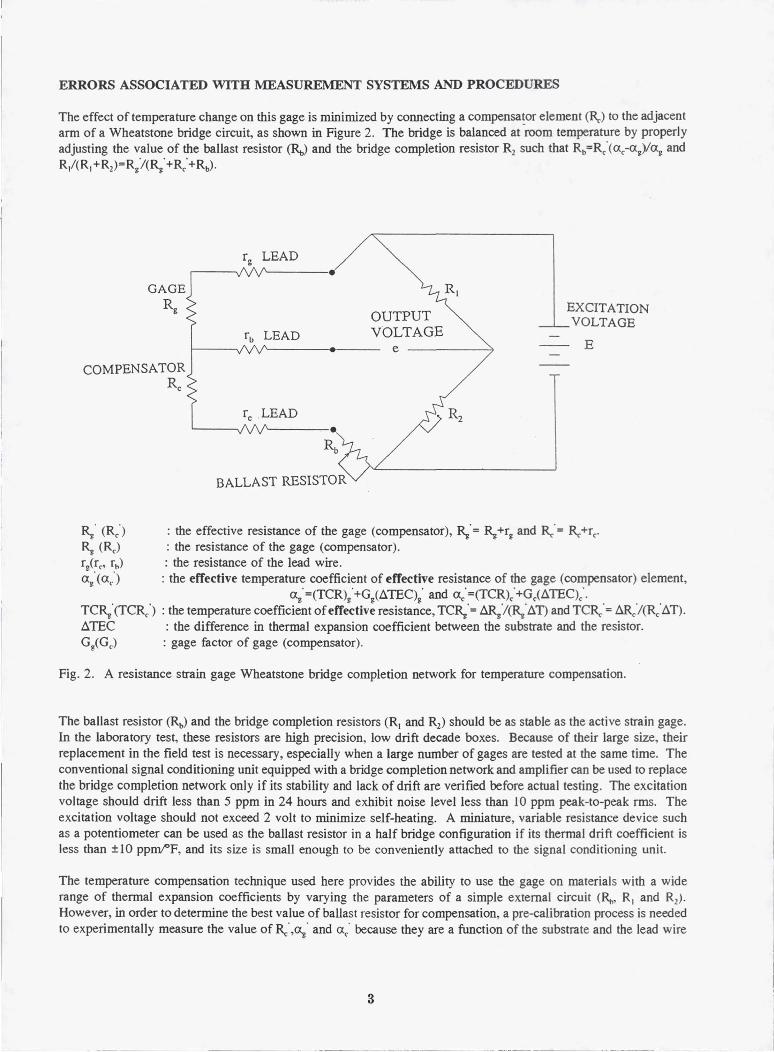
The effect of temperature change on this gage is minimized by connecting a compensa!or element (Rr) to the adjacent arm of a Wheatstone bridge circuit, as shown in Figure 2. The bridge is balanced at room temperature by properly adjusting the value of the ballast resistor (RJ and the bridge completion resistor Rl such that Rb=Rc'« Xc-(X~)I(X~ and R/(RI+Rl)=R/(R~'+Rc'+Rb)'
OUTPUT VOLTAGE
f'------.--- e
EXCITATION VOLTAGE
E
COMPENSATOR Rc
r/rc, r.,} (X~' «Xc)
1'-----.
Rb
BALLAST RESISTOR
: the effective resistance of the gage (compensator), ~. = ~ +r~ and Re' = Re +rc' : the resistance of the gage (compensator). : the resistance of the lead wire. : the effective temperature coefficient of effective resistance of the gage (compensator) element,
(X~'=(TCR)~'+G~(LlTEC)~' and (Xc·=(TCR)c·+Gc(LlTEC)c·· TC~' (TCRc '> : the temperature coefficient of effective resistance, TC~' = LlR/~' Ll n and TCRr' = LlR/(Rc'Ll T). LlTEC : the difference in thermal expansion coefficient between the substrate and the resistor. G/G,.) : gage factor of gage (compensator).
Fig. 2. A resistance strain gage Wheatstone bridge completion network for temperature compensation.
The ballast resistor (Rb) and the bridge completion resistors (R, and R1) should be as stable as the active strain gage. In the laboratory test, these resistors are high precision, low drift decade boxes. Because of their large size, their replacement in the field test is necessary, especially when a large number of gages are tested at the same time. The conventional signal conditioning unit equipped with a bridge completion network and amplifier can be used to replace the bridge completion network only if its stability and lack of drift are verified before actual testing. The excitation voltage should drift less than 5 ppm in 24 hours and exhibit noise level less than 10 ppm peak-to-peak rms. The excitation voltage should not exceed 2 volt to minimize self-heating. A miniature, variable resistance device such as a potentiometer can be used as the ballast resistor in a half bridge configuration if its thermal drift coefficient is less than ±10 ppmt'F, and its size is small enough to be conveniently attached to the signal conditioning unit.
The temperature compensation technique used here provides the ability to use the gage on materials with a wide range of thermal expansion coefficients by varying the parameters of a simple external circuit (R." R, and R1) .
However, in order to determine the best value of ballast resistor for compensation, a pre-calibration process is needed to experimentally measure the value of Re' ,~' and (Xc' because they are a function of the substrate and the lead wire
3
materials. This pre-calibration process is best done on the test article if a thermal cycle to the maximum use temperature is allowed [3].
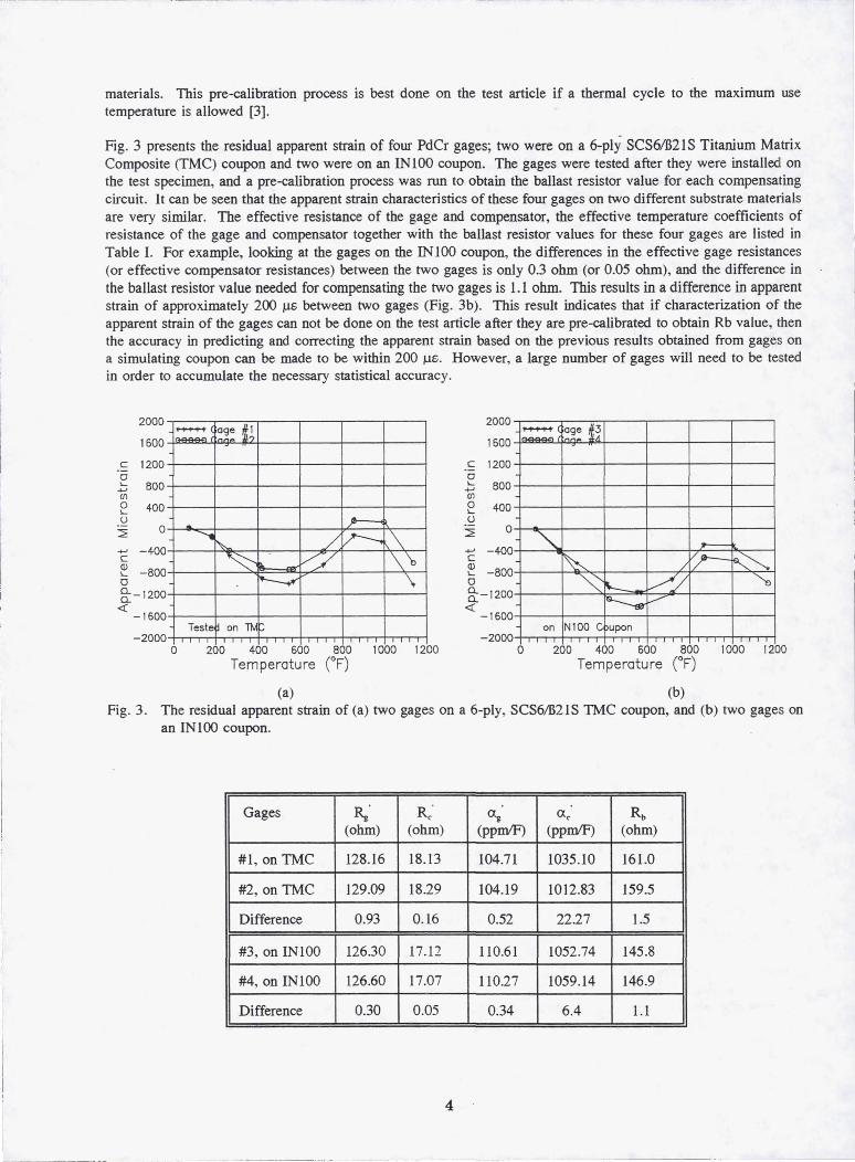
Fig. 3 presents the residual apparent strain of four PdCr gages; two were on a 6-ply SCS61B2lS Titanium Matrix Composite (TMC) coupon and two were on an INIOO coupon. The gages were tested after they were installed on the test specimen, and a pre-calibration process was run to obtain the ballast resistor value for each compensating circuit. It can be seen that the apparent strain characteristics of these four gages on two different substrate materials are very similar. The effective resistance of the gage and compensator, the effective temperature coefficients of resistance of the gage and compensator together with the ballast resistor values for these four gages are listed in Table I. For example, looking at the gages on the IN 100 coupon, the differences in the effective gage resistances (or effective compensator resistances) between the two gages is only 0.3 ohm (or 0.05 ohm), and the difference in the ballast resistor value needed for compensating the two gages is 1.1 ohm. This results in a difference in apparent strain of approximately 200 fJ.S between two gages (Fig. 3b). This result indicates that if characterization of the apparent strain of the gages can not be done on the test article after they are pre-calibrated to obtain Rb value, then the accuracy in predicting and correcting the apparent strain based on the previous results obtained from gages on a simulating coupon can be made to be within 200 /.Is. However, a large number of gages will need to be tested in order to accumulate the necessary statistical accuracy.
2000
1600
c 1200 o I... ..., en o '()
2'
BOO
400
o ..., - 400 c e - BOO o §::- 1200
« -1 600
-2000
......-. ( age ~~ ~
... Jr---< ........ ~ / v---. ,\ ~ ~ \\ --...- \
Teste on TMf-'
o 200 400 600 800 1000 1200 T t (OF) empera ure
2000
1600
c 1200 o I... ..., en o '()
2'
BOO
400
o ..., - 400 c e -800 o §::- 1200
« -1 600
-2000
......-. ( ~~~e 1; I~
'" 1==
~ / jP--~ ~ "'- 7 / ~
~ .--/
on Nl00 C upon
o 200 400 600 800 1000 1200 T t (OF) empera ure
(a) (b) Fig. 3. The residual apparent strain of (a) two gages on a 6-ply, SCS6IB2 1S TMC coupon, and (b) two gages on
an IN 1 00 coupon.
Gages Rg Rc <X@ <Xc Rb (ohm) (ohm) (ppmlF) (ppmIF) (ohm)
#1 , on TMC 128.16 18.13 104.71 1035.10 161.0
#2, on TMC 129.09 18.29 104.19 1012.83 159.5
Difference 0.93 0.16 0.52 22.27 1.5
#3, on INI00 126.30 17.12 110.61 1052.74 145.8
#4, on INI00 126.60 17.07 110.27 1059.14 146.9
Difference 0.30 0.05 0.34 6.4 1.1
4
_._----- - -----------
CONCLUSION
The PdCriPt dual-element temperature-compensated gage is a viable sensor candidate Jor static strain measurements at high temperatures. However, successfully obtaining data from this gage is highly dependent on the purity of the gage materials, the installation materials, the quality of the installation technique and the stability of the measurement system. Attention must be paid to every stage of the applications. This PdCr based gage is best used when a precalibration cycle and an apparent strain characterization cycle are run after the gage is installed on the test specimen and before it is used to measure strain. Two such thermal cycles to the maximum use temperature are needed to provide data for adjusting the compensation circuit and a residual apparent strain curve for later corrections. Statistical work is needed on this gage to insure the accuracy in predicting and correcting the apparent strain in applications such as the NASP where the first thermal cycle data is needed and the pre-calibration and precharacterization processes done on the actual hardware is difficult.
REFERENCES
1. J.-F. Lei, "A resistance Strain Gage with Repeatable and Cancelable Apparent Strain for Use to 800°C", NASA CR- 185256, July 1990.
2. Ed Fichtel, NASA Contract Report CR-191177, 1993
3. J.-F. Lei, "Palladium-Chromium Static Strain Gages for High Temperature", The 1992 NASA Langley Measurement Technology Conference Proceeding, NASA CP-3161, p.189-209, April 1992.
4. J.-F. Lei, D. R. Englund and C. Croom, "The temperature compensation technique for a PdCr resistance strain gage", SEM Fall Conference for Structural Testing Technology At High Temperature Proceeding, p.190-196, Nov. 1991.
5
REPORT DOCUMENTATION PAGE Form Approved
OMB No. 0704-0188 Public report ing burden for this collection of information is estimated to average 1 hour per response. including the time for reviewing instructions. searching existing data sources. gathering and maintaining the data needed. and completing and reviewing the collection of information. Send comments regarding this burden estimate or any other aspect of this collection of information. including suggestions for reducing this burden. to Washington Headquarters Services. Directorate for Information Operations and Reports. 1215 Jefferson Davis Highway. Suite 1204. Arlington. VA 22202-4302. and to the Office of Management and Budget. Paperwork Reduction Project (0704-0188). Washington. DC 20503.
1. AGENCY USE ONLY (Leave blanK) \2. REPORT DATE \3. REPORT TYPE AND DATES COVERED
December 1993 Final Contractor Report
4. TITLE AND SUBTITLE 5. FUNDING NUMBERS
High Temperature Strain Measurement With a Resistance Strain Gage
WU-505-62-5B 6. AUTHOR(S) C-NAS3-25266
Jih-Fen Lei, Ed Fichtel, and Amos McDaniel
7. PERFORMING ORGANIZATION NAME(S) AND ADDRESS(ES) 8. PERFORMING ORGANIZATION
Sverdrup Technology, Inc. REPORT NUMBER
Lewis Research Center Group 2001 Aerospace Parkway E-8300 Brook Park, Ohio 44142
9. SPONSORINGIMONITORING AGENCY NAME(S) AND ADDRESS(ES) 10. SPONSORINGIMONITORING AGENCY REPORT NUMBER
National Aeronautics and Space Administration Lewis Research Center
NASA CR-194441 Cleveland, Ohio 44135-3191
11. SUPPLEMENTARY NOTES
Prepared for the SEM Fall Conference and Exhibit - Structural Testing Technology at High Temperature-IT, Ojai, California, November 8-10,1993. lih-Fen Lei, Sverdrup Technology, Inc., Lewis Research Center Group; Ed Fichtel and Amos McDaniel, Pratt & WhiOley - GESP, West Palm Beach, Florida 33410. Project Manager, W. Dan Williams, Instrumentation and Control Technology Division, (216) 433-3725.
12a. DISTRIBUTION/AVAILABILITY STATEMENT 12b. DISTRIBUTION CODE
Unclassified - Unlimited Subject Category 35
13. ABSTRACT (Maximum 200 words)
A PdCr based electrical resistance strain gage was demonstrated in the laboratory to be a viable sensor candidate for static strain measurement at high temperatures. However, difficulties were encountered while transferring the sensor to field applications. This paper is therefore prepared for recognition and resolution of the problems likely to be encountered with PdCr strain gages in field applications. Errors caused by the measurement system, installation technique and lead wire attachment will be discussed. The limitations and some considerations related to the tempera-ture compensation technique used for this gage will also be addressed.
14. SUBJECT TERMS 15. NUMBER OF PAGES
High temperature measurement; Strain measurement; Strain gage; PdCr alloy; 7
16. PRICE CODE Compensated strain gage A02
17. SECURITY CLASSIFICATION 18. SECURITY CLASSIFICATION 19. SECURITY CLASSIFICATION 20. LIMITATION OF ABSTRACT OF REPORT OF THIS PAGE OF ABSTRACT
Unclassified Unclassified Unclassified
NSN 7540-01-280-5500 Standard Form 298 (Rev. 2-89) Prescribed by ANSI Std. Z39-1B 29B-102
---_. -----

f\Ja
f{on
aJ~eronaumcs a
n[):
Sp
ace
Adm
inis
trat
ion
Lew
is R
esea
rch
Cen
ter
Cle
ve
lan
d,O
H
4413
5-31
91
Offi
cial
Bus
ines
s P
enal
ty f
or P
rivat
e U
se $
300
---_
._
--
~