nuclear information and resource service
TRANSCRIPT
Nuclear information and Resource Service1424 16th St. NW, Suite 404, Washington, DC 20036; 202-328-0002; Fax: 202-462-2183; E-mail: [email protected]; Web: www.nirs.org
April 12, 2005
Peter TamNuclear Reactor RegulationU.S. Nuclear Regulatory CommissionWashington, DC 20555
Mr. Tam:
On behalf of the Nuclear Security Coalition, I am enclosing additional documents assupplemental material to the emergency enforcement petition (10 CFR 2.206) of August10, 2004 which regards the vulnerability of the elevated General Electric Mark I & IIirradiated fuel pools.
The attachments contain calculations prepared by Stephen Lazorchak, P.E., who formerlyworked as a structural engineer at Oyster Creek nuclear generating station, the first GEBoiling Water Reactor Mark I in the United States. Mr. Lazorchak's calculationsindicate that a 1000 lb. object moving at 300 mph striking the refueling deck floor of aMark I at a 300 angle exceeds the Reactor Building's strongest floor beam capacity atElevation 119' by more than 500% and the weakest beam capacity by 8000%.
Additional attachments include letters from Mr. Lazorchak to NORAD/USNORTHCOMexpressing his professional concern about the vulnerability of the supporting structuresaround the Mark I refueling deck and "spent" fuel pool.
Thiyou,
Paul Gunter, DirectorReactor Watchdog Project
Attachments:1) Calculation-Demonstrating Structural Vulnerability of Oyster Creek's Reactor
Building Refueling Floor at Elevation 119'3", Steven M. Lazorchak, P.E.,Consulting Structural Engineer (11 pages)
2) Letter from S. Lazorchak to Admiral Keating (NORAD/USNORTHCOM),f regarding Oyster Creek Nuclear Station- Structural Vulnerability to Terrorist
Attack, Lacey Township, NJ dated February 7, 2005 (3 pages)
£4 oee. c eZ o7
printed on recycled paper dedicated to a sound non-nuclear energy policy. A-f

3) Letter from S. Lazorchak to Admiral Keating/(NORAD/USNORTHCOM),regarding Oyster Creek Nuclear Station- Structural Vulnerability to TerroristAttack, Lacey Township, NJ, dated February 10, 2005 (2 pages)
Cc:Roy Zimmerman, NSIRGlenn Tracey, NSIR

- Structural Vulnerability of Oyster Creek's RxBldg Sheet 1 of 1 1
Calculation
Demonstrating Structural Vulernability ofOyster Creek's Reactor Building Refueling
Floor at elevation 119'-3"
(11 sheets)
Prepared by:
Stephen M. Lazorchak, PEConsulting Structural Engineer
20 Dorchester DriveToms River, New Jersey 08753
Phone/fax 732-255-1972(Past employee of GPU Nuclear/Oyster Creek)
I/--
RxB~dg Floor Elev. 119 OysterCreek.mcd3/30/2005 Page 1
Stephen M. Lazorchak, PEConsulting Structural Engineer

* Structural Vulnerability of Oyster Creek's RxBldg Sheet 2 of 1 1
1.0 PROBLEM STATEMENT:
A sensitivity analysis to determine the affect of aircraft impact on Oyster Creek'sReactor Building, floor elevation 119'. Assume the largest rigid object striking the floorweighs 1000-pounds and is traveling at 300-mph.
2.0 SUMMARY OF RESULTS:
A 1000-pound aircraft component, traveling at 300-mph, striking the floor at a30-degree angle, exceeds the Reactor Building's strongest floor beam's capacity, at119' elevation, by more than 500% and exceeds the weakest beam capacity by8000%. This analysis indicates a large aircraft will likely penetrate the building's topfloor, allowing burning jet fuel to leak down onto vital Reactor shutdown wiring andequipment. The the analysis neglects the weight of the impacting aircraft andcollapsing roof steel onto the floor system around the spent fuel pool. There is a veryhigh probability the spent fuel pool will be severely damaged, causing a leak that will,uncover several hundred tons of radioactive fuel rods.
3.0 REFERENCES:
3.1 EQE Calculation No. 240012-C-003, Oyster Creek Load Drop Analysis,Structural Capacities of Beams and Slabs at El. 119'-3"
4.0 ASSUMPTIONS:
4.1 A large aircraft will impact Oyster Creek's Reactor Building roof at an angle of30-degrees from horizontal, traveling at 300-mph at time of impact.
4.2 The evaluation will determine the effect of a 1000-pound component from anaircraft hitting the concrete floor slab at elevation 119'. The energy of the impact willbe compared to the calculated beam/floor capacities from Reference 3.1.
5.0 DESIGN INPUT:
5.1 Weight of aircraft component Wcomponent : 1000 Ibf
5.2 Velocity of component at impact Vcomponent := 300.mph Vcomponent 440 ftsec
5.3 Acceleration of gravity g = 32.17 22
sec
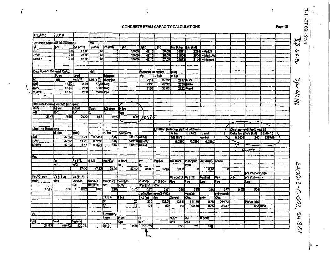
5.4 The maximum beam capacity from SE 2397ft lbfRef. 3.1, Sheet B21, Beam 5B19 Beaxn.5B19 :3976& Sheet 835, Beam 5B39 SEBeam5B39 : 18129. ft. M
6.0 CALCULATION:
Determine the impact energy of a 1000-pound mass, traveling at 300-mph, hitting a floorsystem at a 30-degree angle from horizontal (using mass=weight/acceration of gravity andKE=1/2mV 2 ).
I fWcomponent) 2ImPactEnerg = ( p t) ]~component ImpactEnergy = 3008636 ft. Ibf
RxBldg Floor Elev. 119 OysterCreek.mcd Stephen M. Lazorchak, PE3/30/2005 Page 2 Consulting Structural Engineer

-Structural Vulnerability of Oyster Creek's RxBldg Sheet 3 of 1 1
Determine the vertical and horizontal components from the 1000-pound object hitting a rigidfloor at an angle 30-degrees from horizontal.
Impact angle 0 := 30deg
Verticallmpact.Energy:= (ImpactEnergy)-sin(0)
Horizontallmpact.Energy:= (ImpactEnergy) cos(0)
Verticalimpact.Energy = 1504318 ft Mbf
Horizontallmpact.Energy = 2605555 ft Ibf
Determine the order of magnitude that a 1000-pound object, traveling at 300-mph, will exceedthe capacity of the strongest beam in the Reactor Building's floor at elevation 119'.
Verticalimpact.Energy = 1504317.99 f Mbf
SEBeam.5B19 = 239769ftrlbf
Verticalhmpact.Energy - SEBeam.5B19 5.27
SEBeam.SBI9
Therefore, a 1000-pound object traveling at300-mph, striking the floor at a 30-degreeangle, will hit with a vertical force, that exceedsthe strongest floor beam capacity by more than500%. This evaluation neglects the weight ofthe impacting aircraft and collapsing structuralsteel roof and overhead bridge crane.
SEBea5.5B39 = 18129fi-lbf
VerticalImpact.Energy - SEBeam.5B39 81.98
SEBeam5.B39
Therefore, a 1000-pound object traveling at300-mph, striking the floor at a 30-degreeangle, will hit with a vertical force, that exceedsthe weakest floor beam capacity by more than8000%. This evaluation neglects the weight ofthe impacting aircraft and collapsing structuralsteel roof and overhead bridge crane.
/I f
RxBldg Floor Elev. 119 OysterCreek.mcd3/30/2005 Page 3
Stephen M. Lazorchak, PEConsulting Structural Engineer

OYSTER CREIK REACTOR BUILDING IS STRUCTURALLY OBSOLETEAND NOT ABLE TO PROTECI NUCLEAR FUEL RODS FROM A
TERRORIST AIRCRAFr ATIACK
THE PLANT IS NEITIHER STRUCTURALLY ROBUST OR DESIGNED TO RESIST .AN AIRCRAFT IMPACT
STEEL ROOF TRUSSES SUPPORTINGA SHEET METAL ROOF DECK
EXTERIOR WALLS OF SHEETMETAL SIDING SUPPORTED ONHORIZOTFAL STEEL CHANNELS
AND STEEL COLUMNS
FLOO
:)J POOLThe impact of a large aircraft into the Reactor Buliding's concrete floor at elevation 119'-30 will
[RODS |cause catastrophic building faiure allowing burning fuel to leak down onto the floors below,
Cdamaging vital wiring and equipment needed to shut down the reactor. An aircraft impact will
VESSEL severely damage the spent fuel pool causing a water leak that will uncover tons of radioactivefuel rods. The result of a terrorist attack on Oyster Creeks Reactor Building will exceed a
Chemobyl meltdown event because there is more spent fuel in Oyster Creek's fuel pool thanthere was In Chernobyl's reactor.
FLOOR DRYWELIli i 5 The impact energy from only one 1,000 pound object traveling at 300 mph and hItting the floorUL,,, \,at an angle of 30 degrees above horizontal exceeds the strongest floor beam capacity by more
Ul 1 -Ithan 500%. Impacting the weakest floor beam exceeds the beam's capacity by more than-f[ /8,000%. The order of magnitude of these values clearly demonstrates Oyster Creek's Reactor
r)T1 Building Is an unacceptable safety risk to New Jersey.
The floor beam strengths are from Oyster Creek Calculation No. 240012.C-003, Load Drop
Analysis Structural papacitles of Beams and Slabs at El. 11Y9-3, page B21 and page B35.The energy of the 1,000 pound aircraft component is determined from the Kinetic Energy
CROSS SECTON Equation (1/2mvA2), while neglecting the larger consequences from the impacting aircraft and
CeRrOS Srrvso no too rso collapsing roof steel.VI-.')ItK UKttR KtAUIVK MUILDINU

'/-l 1-yf Uw.I:lY:
CALCULATION COVER SHEET
Calcuation No: 1ZA o i 2-~ e ot~
CalcultltonTille: 5;TP-weTVY2AL CAE'AeAVW61 -6 6&IWM'l Amp~
StLAlBS AT 115.V
Referencus 6 k1=
Attactimerdts: A¶ (7)
Toalt'Iuniber ofPages (Includlng Cover 6he et)::I I
Revision ApprovalN4umber Ctwo Ciscdpt~ln of Revision Orgignator Checker Approver'
wl-W. P OE
N\
X| BIZz rest}
I YZNCa
.I
il.r. ..
* . -l I * I
k
- t'- I{-'d(
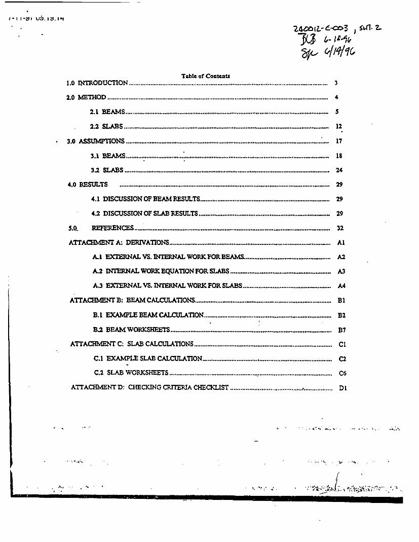
Table of Contents1.0 11IM ODUCTION .................................. , 3
2.0 bEHOD .................. 4
2.1 BEAMS ......... 5
2.2 SLABS ................ _ 12
3.0 ASSUMPTIONS ._ ; 17
3.1 BEAMS ...... _ 18
3.2 SLABS ................................ _ 24
4.0 RESULTS .. 29
4.1 DISCUSSION OF BEAM RESULTS.29
4.2 DISCUSSION OF SLAB RESULTS ................................ .. 29
S.Q REFERENCES . . . . 32
ATTACHMENT A: DERIVAONS .................. Al
A.l EXTERNAL VS. WINTERNAL WORKIFORBEAS . ........................................... A2
A.2 INTERNAL WORK EQUATION FOR SLABS . . A3
A.3 EXTERNAL VS. INTERNAL WORK FOR SLABS ........................................ ... A4
ATTACMENT B: BEAM CALCULATIONS ............................................. BI
B.1 EXAMPLE BEAM CALCULATION . . .B2
B.2 BEAM WORKSHEETS . ... B7
ATTACHMENT C: SLAB CALCULATIONS. . . C
C.1 EXAMPLE SLAB CALCULATION . . .C2
C.2 SLAB WORKSHEETS . . .C6
ATIACMENT D: CHECKING CRITRIA CHECKLIST . . .Dl
- : -. 84 .~~ .- * .
. . h; ~ , . , -, - . . la~i:.asW , ,.l~w :j,-ssf /
'-I1 1 -&y I U9:1 V: 1 4
/2, 1-.6Yf
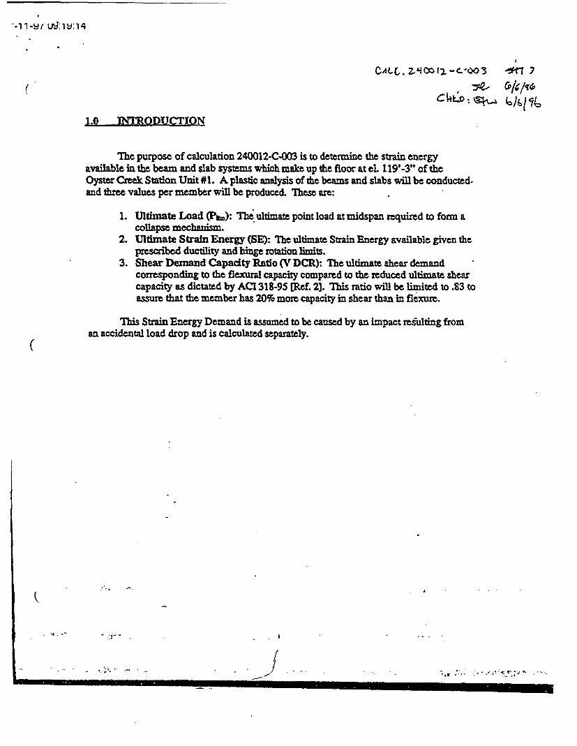
1.0 INTIODUCTION
The purpose of calculation 240012-C-003 is to determine the strain energyavailable in the beam and slab systems which make up the floor at eL 119'-3" of theOyster Creek Station Unit #1. A plastic analysis of te beams and slabs will be conducted.and three values per member will be produced. These are:
1. Ultimate Load (Pin): The ultimate point load at midspan required to form acollapse mechanism.
2. Ultimate Strain Energy (SE): The ultimate Strain Energy available given theprescribed ductility and binge rotation limits.
3. Shear Demand Capadity Ratio (V DCR): The ultimate shear demandcoresponding to the flexural capacity compared to the reduced ultimate shearcapacity as dictated by ACI 318-95 [Ref. 2]. This ratio will be limited to .83 toassure that the member has 20% more capacity in shear than in flexure.
This Strain Energy Demand is assumed to be caused by an impact resulting froman accidental load drop and is calculated separately.
(a
.~- .. ..
- I . , , , -

7-11-97 O:19:14
aALL e-~ %
2.0 METHOD
2.0 Introduction
Plastic analysis methods were used to calculate the ultimate flexural capacity of thebeam and slab systems in accordance with EQE Procedure 240012-P-001.
In general, the beams were modeled assuming fixed support conditions. The loadwhich causes the beam to become a collapse mechanism was then calculated. Since thisload is assumed to occur at midspan of the beam, a lower bound ultimate load will result.A "collapse mechanism" is the point at which hinges form at the ends and at midspan ofthe beam resulting in flexural failure of the system. These plastic hinges occur when theultimate moment capacity of a given section is reached. In this calculation, the ultimatemoment capacity of a section is the allowable nominal moment capacity as calculated inaccordance with ACI 318-95 (Ref. 2]. The ultimate load, P=,. was calculated through thework energy method described in section 2.1. A limiting deflection was then calculatedbased on limited rotational capacities of the beam sections ( Prm). Pan is then multiplied bythe Ar to attain the ultimate strain energy (SE), also referred to as External Work (W.),required to form the collapse mechanism, thus fail the system in flexure.
( The plastic analysis for the slab is based on the same principles as that for thebeam. However, instead of forming 3 hinges, a series of hinged creases, or yield lines areformed. These yield lines are dictated by an end deflected shape which is assumed basedon application of the load to the center of the slab. The slab is assumed to be fixed on allsides. Based on reinforcement properties of the slab, moment capacities are calculated ateach yield line. These capacities are used to calculate the internal work required to yieldthe system. The internal work is then used to back out the ultimate load (P&m) to yield thesystem. The rest of the process (calculation of Al. and SE) is the same as for the beam.
This section is comprised of:
2.1 Summary and explanation of the plastic analysis process for a beam.2.2 Summary and explanation of the plastic analysis process for a slab.
2. umr n *1ntino h lsi nlyi rcs o lb
I .'

)7-1 1-97 d9:1 9:14
EOZ IMERNAIIONAL
JOB NO. ___J_
CALC. NO._ __ SI
DsC
i it ien
A? Z "7- Zt C -01-1- -
SHEET NO. .SBY DATE fi/n .CHK -i \ DATE / "'- .
2.0 MvrkaM:
2.1 | ta AM4
Ti4C- CfNZYW41 MZS .;400 '504 CA CCLR 6r)WC- YSErLI &v
Pboi-r Lo-*4 AT.-M)OSPA-vi Of A I5Dh4I.% 12-6tt2A&P 70 Sti#LO T4&
5SY;.- .' - -Av I 'S As We -. oS S.AYL V- 13SAM..
)AwVST P5& eC>e-V1:> 'r 1w5,,,nx !5h9fl_ FAIlvof * -0- "roe PA&W.-
VL-KV">, ' I- V t OrrL .
/~
!;um&A&4 MVTU-
1.
-3.
4.
6.
C.
-7.
e.Iq.10.
r% :.a
CAh-%&v 0DA0 L~OAD HOI*;-% DEMMM4 NO06
CevrUls~ Ctautg~ta& POX~'T to r% Q&EV~tP XSIoV,4aL~
C"-c.v&-r, 'OsY N=JX TA)~ seL.' 1Fj tIC',.?F S (AU )T ~ 6 T ~ ~ a d ~ L r A T A .0 '2 3 & A A-
CA LC-\ L^-AT3 BrXI£ft"AL WOVX0\C.5{
4 A. CY&L. L/4 T frfA - 5ArJ &A. A E 1o 3&-SCA C-Vu-Cre tcove-go HiJMINAL- 'ShCAtL GD'..ti or-
6, ; . o. .. .. ) .A A .. )
... . . ............ .
(
CONCRETE BEAM CAPACITY CALCULATIONS Page 15
OFEAM: 15819--- ---- -
ultimte MornctaCatcutaton: Mu - -
M ph As (WZ Fy M ? hMP"d bm Mpk) -Mp (k-SWE 0.9 17.00 40 3 50.00 47.12 36.00 26571 -221-
NIN 0.9 23.00 40 3 50.00 47.12 38.0 34888 2900 aMp NANMiddle 0.9 16.00 40 3 -50.0 47.12 57.00 25873 2156 wMpmid _
Dead Load MomentCak: Mdl Momefft at y -
_ Spn Mooera dN o Md - -neM I (t) w ) Udl( dbtecion 2214 87.32 2147 Msh -
SWE 18.5Q 2.36 8732 Ne- 290 67.32 2838 MmA*NHM 18.50 2.36 67.32 N_! 21t6 33,66 2122 MmidMiddle 18.50 2.3 33.6 -_
UltimateBeam Load p Mid : - _. .Ms/e Mnl- Mmid o on een __ __I
_I-__ -i__ -_-X-11 Ik-ft k-ft ft Ift
21471 2838 2122 0.18b .2
L.mitin Itoblis - ._._ llnta Ro*Uon End of Dowa Dhsonltnt Umit and SEd m ¢ nt rtl _n ____ti Nm. tie "U2 nubeid t .We (k-f) SE Pb-f.\
S/E 47.12 871 0.5351 0.07 0.0351 Wa SE SIE N/VW - Om
NNW 47.12 11.79 o .7 0.0260 m NMI -0 0.0296 0.0280 0 J
Mlddte 47.12 5.1i e 0.0m 0.07 0.0591 nt mid
Vn:Yn:_r¢ AsSE dB /E AsINW d NN bw Im SIE 4NIWA __s_ _p__t
kd h^'2 In - In _____
ksi 3 17.0I 47.12 23.00 47.12 In 00 2214 2906 31 0.40 -
V Vc(11.3) V(11-5) Vcorol |VcIblmt W Vow Vs= phis PNVnbean
dmin kipUp VuW" VC(114$ Uowp )II(1) klpj kW kips Id" - -
SE NSEWit SWE NNV NAN Int .=W47.12 186 '0.92 0.9 216 0.70 0,70 217 218 325 218 377 0.8OA 54
- beff e rs~pawn - Vc slab I ptvnsfb - -l -
= _ th * t (in8 8xt (I) (n) Conrwol 1 *P - -
- 28 208 121.5 121.5 311.451 0.85 284.73 hIPVnt ola- (ij 16 128 63 63 99.381 0.85 84.47 853lpe
Vu: ___ - - Si~mwna:
-iatI I JSE Om___ VDCR __
.dl Vext .Vul Id - k.
21.83 498.92 520.7s5 - S- d 9%1 239769 - 83 521 0.61
-4
.J.0Co
EDp
oD i
v
cAICIn-
L.

I,
\
CONCRETE BEAM CAPACITY CALCULATIONS Page 30
BEAM: 5839 |, ___. .
Ultimate Moment Cdaulafor. Mu
§t &-I As on - Fy hPOO) bp (In) Mp fkiR) M tSIE 0.9 000n 40 3 30.00 27.00 0NW 0.9 0.00 40 3- 30.00 2725 27.00 0 O NAN - -
mime 0.9 3.95 40 3 30.0 2a25 48.001 32 7 M id
Dead Load Monent Caic.: dl - Mornent Cap (k-ft) ' -
__ Span Lad Moment -Mdl M net - -
M I (_ ) wMI) - *(R dre4on 5.02 -45 Ms -
S/E 20.25 `1.33 45.42 N D 0 4t.42 -45 ANNNm 20.25 1.33 45.42 N327__2____11 30 M mW--IMkddh 20.25 1.33 22.71 Pas
U(Ifmate Be= Load 0MidsI_ _ _
Mnsv mmM* Spa 12am Pu fix- M m .l d.
k-ftl k-ft I-ft ft A _ _ I.45 -45 304 202 10.12 61 i
Lrniting Rotatio - -_ -_ __to D_. LWm- and SE SI
Id Mh) c n) ru cm"l _ _sm". lnm ld2 nsend_ Il Def (o S~b-l.) _S/E 27.25 0.00 WA ON 0.07W 0 Si E - - -I hl N k 0.354 Is L!t8
NM 27.25 o oa WA o0.0700 u Nm 0.0700 0.35 0.05Middle 2825 1.2 0.1209 0.07 0.0700 rumMd
Vn_ro AsSteAs dNMt MuFSIE- MNtums iV N stWir
3 0.00 2725 000 27.26 27.00 0 0 O b er 0.40 121I I PM Vn fVo+Vs2-
Va ACI emn Vo (1 13) Voill.WI -.- p-w P Vh b
_ ISIw'n*' sm mit NW N W ._, Nl27.25 SIN/A 1.00 77 WA Igo 77 81 141 81 3 0.85 9.
-b __ _ beffectivis a2-/ Vo stab lvsn
-hicke tJ fxtoln () Conmw lop WMl K -
- - - i() 16 1281 22.5 22.5 35.49 0.85 30.17 Pllmft a|=
I__ (b) 26 208 115.5 115.5 296.07 O0S 251.66 3811
Vu: - Stmyt-'..___Seem IP sm SE ph9h Vu V OCR
Vdl VeA Vutota1 _ Ip bit .-3,- - - - - -
13.461 25.581 _ -9 04 O I61 181291 8I 3 - .0
-'i
rb
I0
(Oi
v.
F
Si
M'.
eZ~
(b
0IrA
(AZOQbM
L`\
I

II
Stephen M. Lazorchak, P.E.Consulting Structural Engineer20 Dorchester DriveToms River, New Jersey 08753(732) 255-1972 fax (732) 255-1972
February 7, 2005
Admiral Timothy J. Keating c ooNORA D/USNORTHCOM250 Vandenberg, Ste. B-016Peterson AFB, CO 80914-3808
Re: Oyster Creek Nuclear Station - Structural VulnerabilitY to Terrorist AttackLacev Township, NJ
Dear Admiral Keating:
On Friday February 4, 2005, two planes landed without incident at John F. Kennedy InternationalAirport, New York, after authorities received reports that Delta Fight 119 from Paris and DeltaFlight 81 from Amsterdam, Netherlands had been threatened. Both planes landed about 1330and were momentarily held back from the gate. One news report stated Flight 119 was escortedby F16 fighters. Lt. Cmdr. Sean Kelly said NORAD did not send escort jets, "the situation didn'twarrant it."
This incident prompted me to write you because NORAD/USNORTHCOM may not be aware ofthe structural vulnerabilities in Oyster Creek's Reactor Building, located approximately 60 milessouth of JFK International AirpQrt. Oyster Creek is one 22 nuclear power plant sites (affectingapproximately 30,000 Megawatts of generation) with an obsolete boiling water reactor buildingdesign.
Oyster Creek's Reactor Building Design:Oyster Creek's Reactor Building is a square building that can be easily seen from Route 9. Thebuilding's ground floor is at elevation 35'-0", the, highest floor level is at elevation 119'-3"(typically known as the refueling floor). Below elevation 119', the Reactor Building is aconcrete structure, above elevation 119' is steel framing about 50' high, supporting steel rooftrusses. The whole steel framing system is covered with sheet metal siding.
The Reactor Building refueling floor is a large open space. During plant operation, one couldwalk over to the spent fuel pool, look down, and see several hundred tons of used radioactivefuel rods stored under 30-feet of water. The metal buildiyg enclosure above the spent fuel pool is
2005 Feb 7-NORAD Page I of 3

d
Oyster Creek Nuclear Station
not robust, nor will it prevent a terrorist aircraft from impacting into the pool or onto the ReactorBuilding refueling floor.
The NRC's basic policy on the protection of nuclear facilities is laid down in regulation 10 CFR50.13. Essentially, regulation limits the licensee's responsibility for defending a nuclear facility.Any gap in the licensee's capabilities to defend against a kamikaze assault using a large aircraft,are assumed to be provided by the Government. The NRC is not required to notify othergovernment agencies about nuclear power plant vulnerabilities that may affect national security.
In August 2004, NRC Chairman Diaz was provided Oyster Creek's reference to the ReactorBuilding load drop calculation at floor elevation 119'-3". Using the calculation, it can bedemonstrated an aircraft impacting the reactor building refueling floor will pass through it,critically damaging the spent fuel pool ......... resulting in a Chernobyl event.
The National Academy of Science, Board on Radioactive Waste Management prepared aconfidential Committee report on the "Safety and Security of Commercial Spent Fuel Storage"(Project No. BRWM-U-03-05-A). The report was issued to the Congress, the NuclearRegulatory Commission, and the Department of Homeland Security, in July 2004.
On Dec. 2, 2004, NRC Chairman Diaz spoke before the Nuclear Security Executive Forum andstated in his closing remarks;
"I would be remiss if I did not address further the issue that makes the most headlines: theintentional crash of an aircraft on a nuclear power plant. The NRC has conducted extensiveanalyses of the capability of representative nuclear power plants to withstand an aircraft attack.While these analyses are classified, the studies confirm that the likelihood of damaging thereactor core and releasing radioactivity that could affect public health and safety is low. "
Based on the Chairman's remarks, it appears the report on "Safety and Security of CommercialSpent Fuel Storage" neglects a reactor building design like Oyster Creek, or it significantly overestimates a reactor building's structural capacity to resist aircraft impact. The BRWMCommittee reviewed my evaluation of Oyster Creek's refueling floor, but I don't know if theywill amend the classified report.
Oyster Creek's sheet metal covered superstructure, located over the spent fuel pool, is notdesigned for aircraft impact. The World Trade Center towers were designed for the impact by aBoeing 707 jetliner, but not the burning fuel after the crash. A much larger Boeing 767 hit theWTC towers, the 767 is 225% heavier than the 707. From a structural engineering viewpoint,Oyster Creek's Reactor Building is significantly weaker than the WTC towers.
The impact energy from only one 1,000 pound object traveling at 300 mph and hitting OysterCreek's refueling floor at an angle of 30 degrees above horizontal, exceeds the strongest floorbeam capacity more than 500%. Impacting the weakest floor beam exceeds the beam's
2005 Feb 7-NORAD Page 2 of 3

- Oyster Creek Nuclear Station
capacity by more than 8,000%. The order of magnitude of these values clearly demonstratesOyster Creek's Reactor Building is an unacceptable safety risk to New Jersey.
The NRC and Federal government needs to clearly identify the measures taken to mitigate anaircraft attack on structurally obsolete reactor buildings, like Oyster Creek. Otherwise,pronuclear individuals like me cannot support the continued operation of these plants, anddemand their immediate shutdown. The loss of 450 Oyster Creek jobs and higher electric ratesare a trivial concern to many thousands of Ocean County residents and property owners,compared to the consequences of a potential Chernobyl event, should terrorist attack the plant'sReactor Building.
I urge you to verify that existing NORAD/USNORTHCOM operational procedures and trainingscenarios include the protection of nuclear power plants like Oyster Creek. In my opinion, thissecurity concern is the most difficult to solve because it relies on the efforts of thousands ofpeople to perform their jobs perfectly, within a very limited time. The use of multiple overseasaircraft, like Delta Fight 119 and Delta Flight 81, should be expected in any real terrorist attackusing a large aircraft as a guided missile.
Sincerely,
Stephen M. Lazorchak, P.E.Past employee of GPU Nuclear/Oyster Creek
Enclosures: Oyster Creek Aircraft Impact Handout (2 sheet)
Oyster Creek Nuclear Power Plant, The Structural Vulnerability to a TerroristAttack, Forked River, NJ (4 sheets)
List of U.S. Commercial Reactors with Elevated Irradiated Fuel Storage Pools (1sheet)
Photograph of Oyster Creek Nuclear Power Plant (I sheet)
Calculation demonstrating structural vulnerability of Oyster Creek's ReactorBuilding refueling floor at elevation 119'-3" (9 sheets)
2005 Feb 7-NORAD Page 3 of 3
Stephen M. Lazorchak, P.E.Consulting Structural Engineer
l l 20 Dorchester DriveToms River, New Jersey 08753(732) 255-1972 fax (732) 255-1972
February 10, 2005
Admiral Timothy J. Keating ( 00 PyNORAD/IUSNORTHCOM250 Vandenberg, Ste. B-016Peterson AFB, CO 80914-3808
Re: Oyster Creek Nuclear Station - Structural Vulnerability to Terrorist AttackLacev Township. NJ
Dear Admiral Keating:
The National Academy of Science, Board on Radioactive Waste Management (BRWM) prepareda confidential Committee report on the "Safety and Security of Commercial Spent Fuel Storage"(Project No. BRWM-U-03-05-A). It was issued to the Congress, the Nuclear RegulatoryCommission, and the Department of Homeland Security, in July 2004. I urge you to contactBRWM Director Kevin D. Crowley (phone 202-334-3066) to obtain a copy of the classifiedspent fuel storage report. NORAD/USNORTHCOM must become an expert on the structuraldesign vulnerabilities of our nuclear power plants and prevent terrorist attacking these plants withlarge aircraft, used as a guided missile. Currently there is an effort to rebuild the World TradeCenter. However, if a nuclear power plant like Oyster Creek was destroyed in a 9/11 event, mostof New Jersey will emulate the area around ChernobyL
Several days ago I mailed you an information package detailing my concerns regarding the spentfuel storage pool at Oyster Creek Nuclear Station. Briefly stated, Oyster Creek's reactor buildingis an obsolete structural design, no longer allowed by current Nuclear Regulatory Commissionstandards. Located on the top floor of the Reactor Building, 84-feet above ground level, is therefueling floor. At one corner of the building is a stair/elevator tower, immediately adjacent tothe elevator is a 30-foot square floor opening to move refueling equipment between the groundlevel and the refueling floor. Diagonally across the refueling floor from the stair/elevator toweris the spent fuel storage pool.
Authorized plant personnel can walk over to the fuel pool handrail, look dowr4 and see 700-tonsof used radioactive fuel rods stored under 30-feet of water. Looking up fromn the fuel pool, onewill see steel roof trusses and the underside of the sheet metal roof decking. An overhead bridgecrane will be typically parked at one end of the building. The roof trusses •pan the full width of
2005 Feb 10-NORAD Page I of 2
Oyster Creek Nuclear Station
the structure and are supported by steel columns. Attached to the steel columns are horizontalsteel channels spaced vertically 6-feet on center. Sheet metal siding is attached to the channelmembers. This whole metal building enclosure, located above the refueling floor, is part of thesecondary containment structure. It is designed for severe wind and earthquake forces, but notfor aircraft impact. The metal enclosure is the weakest structural system in the ReactorBuilding's design.
Below the refueling floor the Reactor Building is made of reinforced concrete several feet thick.All vital plant equipment required to shut down the reactor and maintain cooling to the spent fuelstorage pool is located within the concrete portion of the building.
As part of a NRC directive, Oyster Creek was required to prepare load drop calculations for allfloor levels within the Reactor Building. The calculations identify the amount of energy tocritically damage floor slabs and floor beams, without allowing an accidental dropped load frompenetrating the floor system. Using a Kinetic Energy Equation (1/2 mv 2) to determine the force aheavy object will hit the floor and the load drop calculation for the refueling floor, one candetermine if a unsafe structural concern exists.
The impact energy from only one 1,000 pound object traveling at 300 mph and
hitting the Reactor Building's refueling floor at an angle of 30 degrees above
horizontal, exceeds the strongest floor beam capacity by more than 500%.
Impacting the weakest floor beam exceeds the beam's capacity by more than
8,000%. The order of magnitude of these values clearly demonstrates Oyster
Creek's Reactor Building is an unacceptable safety risk to New Jersey, if a plane
was intentionally crashed into the building.
[American Airlines Flight 11 crashed into WTC Tower I at 350 mph, and United
Airlines Flight 175 crashed into WTC Tower 2 at 550 mph. Oyster Creek's
relicensing website (www.oystercreeklr.com) references an EPRI December 23,
2002 report showing aircraft could not breach nuclear structures. This report
analyzed a cylindrical dome structure, not Oyster Creek's square reactor
building. The EPRI Report used an impact velocity of 350 mph, at 550 mph a
large aircraft will penetrate the structural model used in the EPRI Report].
I hope NORAD/USNORTHCOM training scenarios include multiple terrorist aircraft thatdisappear from FAA control, turn to attack a nuclear power plant and another vital target close toan international airport. New Jersey's Newark International Airport and New York's JFK areexcellent locations to test the military's response to such a threat.
Sincerely,- COPY
Stephen M. Lazorchak, P.E. /Past employee of GPU NuclearOyster Creek
2005 Feb 10-NORAD Page 2 of 2