nuclear safety guide tid-7016 revision 2
TRANSCRIPT
NUREG/CR-00S5 ORNL/NUREG/CSD-6
Nuclear Safety Guide TID-7016 Revision 2
Prepared for the U.S. Nuclear Regulatory Commission Office of Nuclear Regulatory Research
Under Interigency Agreement DOE 40-550-75

BLANK PAGE

NUREG/CR-0095 ORNL/NUREG/CSEM3
Distribution Category RC
\
Conbact No. W-7405 eng 26
NUCLEAR SAFETY GUIDE
TID-7016
REVISION 2
J. T. Thomas, Ed.
Computer Sciences Division
Manuscript Completed: May 1,1978
Date Publ ished: June 1978
-mona-P ^y • • » »^^^^B #M^V V^^VHMMHit M B W WH
* B™ ^Rf •» BUT i*a^B^ ip» MT a^y •» WtVF
PREPARED FOR THE U.S. NUCLEAR REGULATORY COMMISSION OFFICE OF NUCLEAR REGULATORY RESEARCH
UNDER INTERAGENCY AGREEMENT DOE 40-550-75 NRC FIN No. BO 163-6
UNION CARBIDE CORPORATION, NUCLEAR DIVISION operating the
Oak Ridge Gaseous Diffusion Plant . Oak Ridge National Laboratory Oak Ridge Y-12 Plant . Paducah Gaseous Diffusion Plant
for the DEPARTMENT OF ENERGY
DISTRIBUTION u ,.i I.-, UNUrtlTiiJJ
TABLE OF CONTtJTj
Page
Preface to Second Revision vii Preface to TID-7016 ix List of Figures . ; xi List of Tables . ; . xv Chapter I Background . I
Pail I: The Nuclear Criticality-Safety Problem S Introduction I Safety Fundamentals I Factors Affecting Criticality Safety 2 Sources of Criticality Information
Experimental Data .».„',. 5 Theoretical Data 5
Criticality Indices , , , . ' . . - 5
Part II: Nuclear Criticality Safety Practices 7 The General Criticality Safety Standard , 7 Administrative Practices 7
Responsibilities 7 Other Administrative Practices 8
Technical Practices 8 Double Contingency Principle 9 Geometry Control 9 Control by Neutron Absorbers 9 Subcritical Limits 9
Instrumentation 10
Part III: Safety Experience 13 General 13 Plant Accidents , 14
The Y-12 Plant, Oak Ridge - June 16, 1958 14 The Los Alamos Scientific Laboratory - December 30, 1958 14 The Idaho Chemical Processing Plant, National Reactor
Testing Station - October 16, i959 « 15 The Idaho Chemical Processing Plant, National Reactor
Testing Station - January 25, I96i ; 16 The Recuplex Plant, Hanford - April 7, 1962 16 Wood River Junction Plant. RI - July 24, 1964 17 UKAEA Windscale Works - August 24, 1970 18 Other Observations , 18
Criticality Risk in Perspective 21 Chapter II Limits for Individual Units 23
Part I: Single-Parameter Limits for Fissile Nuclides , 23 Introduction 23 Hydrogen-Moderated Systems , . . 23
Uniform Aqueous Solutions 23 Homogeneous Mixtures and Uniform Slurries , 24 Nonuniform Slurries 24
Metal Units 25
iii

Part II: Concentratuit-Depcndent Limits 27 Aqueous Solutions and Metal-Water Mixtures 27 SlightN Enriched Uranium (^ 5 wt % 2 , 5 U) 40
Part III: Mixtures of Nuclides 47 Plutonium-Uranium Mixtures 47
Solutions and Uniform Aqueous Mixtures 47 Dry tzd Damp Mixed-Oxide Powders 47 Subcritical Plutonium Concentrations for Unlimited Quantities of
Plutonium and Natural Uranium Materials.... 53 Subcritical Plutonium Concentrations for Uniform Aqueous Mixtures
of Plutonium and Natural Uranium Materials S3 Mixtures of 2 , , U , Carbon.and Water with M J Th 55 2>,U-Water-Graphite Mixtures 55
Part IV: Special Geometries 65 Annular Cylinders 65 Pipe Intersections 65
Chapter III Factors Affeciing Limits of Individual Units 69 Typical Contingencies 69 Extended Subcritical Limits 69
Reduced Density 69 Dilution of Metals 71 Intermediate 3 , 5 U Enrichment 71 Plutonium Containing 2**Pu 75 Neutron Absorbers 75 Solid Neutron Absorbers 75 Soluble Neutron Absorbers 86 Shape 80 Concrete 80
Chapter IV Storage and Transportation 87 Part I: Limits for Arrays 87
Alternate Storage Criteria 88 Transportation 93
Part II: Neutron Interaction 95 Surface Density. Density Analogue, and Solid Angle Models 95
Surface Density 95 Density Analogue 96 Solid Angle 97
Other Methods 101
Chapter V Nuclear Safety in Processing Plants 103 Training 103 Criticality Alarms 103 Emergency Planning , 104 Plant Applications 104
Dissolver for Water-Reactor Fuel 104 Storage of Low-Enrichment Uranium Solution 105 Solution in Boro%ilicate-Glass Pipe 105
iv

Solution in Tanks Packed with Boron-Containing Raschig Rings 105 Soluble Neutron Absorber 107 Pipe Intersection Design 107 Solution Holdup Design 108 Transportation of U(30) as Oxide 108 A Storage Array for U(93) Metal 109 Fuel Element Fabrication 110
Appendix: Criticality of Special Actinide Elements 117 Odd-N Nuclides 117 Even-N Nuclides 117 A Precaution Concerning Mixtures of ^Cm and ^Cm 119 Safety Limits for Special Actinide Elements 119
Acknowledgments 121
References 123
v
Preface to Second Revision
The Nuclear Safety Guide was first issued in I9S6 as classified AEC report LA-2063 and was reprinted the next year, unclassified, as TID-7016. Revision I. published in 1961. extended the scope and refined the guiding information. The present revision of the Guide differs significantly from its predecessor in that the latter was intentionally conservative in its recommendations. Firmly based on experimental evidence of criticality, the original Guide and the first revision were considered to be of most value to organizations whose activities with fissionable materials were not extensive and, secondarily, that it would serve as a point of departure for members of established nuclear safety teams, experienced in the field.
The reader will find a significant change in the character of information presented in this version. Nuclear Criticality Safety has matured in the past twelve years. The advance of calculafional capability has permitted validated calculations to extend and substitute for experimental acta. The broadened data base has enabled better interpolation, extension, and understanding of available information, especially in areas previously addressed by undefined but adequate factors of safety. The content ha< been thereby enriched in qualitative guidance. The information inherently contains, and the user can recapture, the quantitative guidance characteristic of the former Guides by employing appropriate safety factors. In fact, it becomes incumbent on the Criticality Safety Specialist to necessarily impose safety factors consistent with the possible normal and abnormal credible contingencies of an operation as revealed by his evaluation.
In its present form the Guide easily becomes a suitable module in any compendium or handbook tailored for internal use by organizations. It is hoped the Guide will continue to serve immediate needs and will encourage continuing and more comprehensive efforts toward organizing nuclear criticaluv safety information.
H K. Clark. SRI. I. D. Clayton. BNWL c. B. Johnson. ORM-H. C. Paxton. LASI. D. R. Smith. LASL J. T. Thomas. ORNL. Chairman
VII
PREFACE TO T1D-7016
The Nuclear Safety Guide was conceived by a group that met at the Rocky Flats Plant, October 1955.10 discuss industrial nuclear safety problems. A committee was selected to prepare a draft for consideration by the group during the following meeting at the Hanford Atomic Products Operation. June 1956. Although the resulting Guide remains controversial in form and general content, differences of opinion concerning specific regulations have been resolved (quite generally in favor of the more restrictive versions). In addition to the committee of authors, the following are members of the nuclear safety group who reviewed drafts of the Guide and contributed suggestions.
Dow Chemical Co. (Rocky Rats): M. C. Arthur and D. F. Smith E. I. du Pont de Nemours and Co.. Inc. (Savannah Rivet): H. K. Clark Genera! Electric Company (ANPD): F. G. Boyle General Electric Company (Hanford): G. W. Anthony. E. D. Clayton. D. E. Davenport. X.
Kei/iach. D. D. Lanning. and r.. '." Stuart Goodyear Atomic Corporation: D H. Francu and F. E. Woltz Los Alamos Scientific laboratory: J. A. Grundl Phillips Petroleum Co. (NRTS): R. B. I emon
Union Carbide Nuclear Company (K-25): H. F. Henry'. A. J. Mallett. and C. E. New Ion L'nio.i Carbide Nuclear Company (ORNL): R. Gwin and J. T. Thomas Union Carbide Nuclear Company (Y-12): J. D. McLendon and J. W. Wachter University of California Radiation Laboratory (Livermoore): C. G. Andre and F. A.
Klo\erstrom It is recognized that the Guide is neither handbook (too ambitious for a start) nor manual (a separate problem for each installation). It is hoped, however, that it serves immediate needs for guidance and that it encourages continuing, more comprehensive efforts toward organizing nuclear safety information.
A. D. Callihan. ORNL
W J. O/eroff. Hanford Works
H. D. Paxtcn. LASI C. I. Schuske. Rockv flats
(1957)
IX

LIST OF FIGURES
FIGURE PAGE
I.l. Approximate correlation of exposure with distance from a solution excursion of 1017 fissions. Arrows appear where it is believed that available estimates are displaced from the probable values 19
2.1. Subcritical mass limits for individual spheres of homogeneous water-reflected and •moderated 2 J 5 U 28
2.2. Subcritical volume limits lor individual spheres of homogeneous water-reflected and-moderated 2 > 5 U 29
2.3. Subcritical diameter limits for individual cylinders of homogeneous water-reflected and -moderated " 5 U 30
2.4. Subcritical thickness limits for individual slabs of homogeneous water-reflected and -moderated 2 J 5 U 31
2.5. Subcritical mass limits for individual spheres of homogeneous water-reflected and -moderated 2 , J U 32
2.6. Subcritical volume limits for individual spheres of homogeneous water-reflected and -moderated 2 H U 33
2.7. Subcritical diameter limits for individual cylinders of homogeneous water-reflected and -moderated " J U .-. 34
2.8. Subcritical thickness limits for individual slabs of homogeneous water-reflected and -moderated 2 M Pu 35
2.9. Subcritical mass limits for individual spheres of homogeneous water-reflected and -moderated "*Pu 36
2.10. Subcritical volume limits for individual spheres of homogeneous water-reflected and -moderated "*Pu 37
2.11. Subcritical diameter limits for individual cylinders of homogeneous water-reflected and -moderated 2 W Pu 38
2.12. Subcritical thickness limits for individual slabs of homogeneous water-reflected and -moderated 2>*Pu 39
2.13. Subcritical mass limits for individual spheres of water-reflected and -moderated U(«S 5) 42
2.14. Subcritical volume limits for individual spheres of water-reflected and -moderated U(C5) 43
2.15. Subcritica' diameter limits for individual cylinders of water-reflected and -moderated UK 5) 44

JP*> l C y ^-->ya . - . y - . . , ^ , • ^ - - ^ • ^ ^ • • ^ - • - - • . . a w - * -
BLANK PAGE

2.16. Subcritical thickness limits for individual slabs of water-reflected and -moderated U(«S 5) 45
2.17. Subcritical area! density limits for individual water-reflected and -moderated units of U(^ 5) 46
2.18. Subcritical mass limits for water-reflected individual spheres of aqueous homogeneous mixtures of PuO; and U(0.7)O;. The small quantities of :"Pu and 2 J 2Pu expected in these isotopic mixtures are considered to have a negligible effect on the limits 48
2.19. Subcritical volume limits for water-reflected individual spheres of aqueous homogeneous mixtures of PuO: and L"(0.7)O:. The small quantities of m P u and 2 4 2 Pu expected in these isotopic mixtures are considered to have a negligible effect on the limits 49
2.20. Subcritical diameter limits for water-reflected individual cylinders of aqueous homogeneous mixtures of PuO; and L(0 7)0 ; . The small quantities of '"Pu and 2 4 2Pu expected in these isotopic mixtures are considered to have a negligible effect on the limits 50
2.21. Subcritical thickness limits for w^ter-rcflected individual slabs of aqueous homogeneous mixtures ol PuO; and U(0.7)O;. The sm?H quantities of ""Pu and 2*2Pu expected in these isotopic mixtures are considered to have a negligible effect on the limits 51
2.22. Subcritical areal density limits for water-reflected individual units of aqueous homogeneous mixtures of PuO. and U(0.7)O.>. The small quantities of : ,*Pu and : 4 2 Pu expected in these isotopic mixtures are considered to have a negligible effect on the limits 52
2.23. Subcritical mass limits for water-reflected individual spheres of homogencou> :"L'0:-carbon mixtures containing various amounts of water 56
2.24. Subcritical radial limits for water-reflected individual cylinders of homogeneous : , ,UO-carbon mixtures 57
2.25. Subcritical mass limits for water-ieflected individual spheres of homogeneous mVO: and ":ThO.- mixtures 58
2.26. Subcritical radial limits for water-reflected individual cylinders of homogeneous 2 " l ' 0 : and 2 , 2 ThO ; mixtures 59
2.27. Subcritica! mass limits for water-reflected ind'vidual spheres of homogeneous mVO:. 2 , 2ThO ; . carbon, and water mixtures * ifh Th:l'=l ftO
?.28. Subcritical radial limits for water-reflected individual cylinders of homogeneous ;"UO;. 2 , :ThO.. carbon, and waier mixtures with Th:U=l 61
2.29. Subcritical mass limits for water-reflected individual spheres of homogeneous J"UO ;. 2 , ; ThO ; . carbon, and water mixtures with Th:li=4 62
xii

2.30. Subcritical radial limits for water-reflected individual cylinders of homogeneous 2 3 1UO;, a 2 ThO:, carbon, and water mixtures with Th:U= 4 63
3.1. Factors by which subcritical mass limits for metals and unmoderated compounds of fissile materials may be increased when densities are less than theoretical 70
3.2. Factors by which subcritical mass limits for fissile metals may be increased as a result of dilution by nonmoderating elements 11 ^ Z ^ 83 72
3.3. Factors by which 2 3 5 U metal subcritical mass limits may be increased for reduced uranium enrichment 73
3.4. Factors by which the subcritical limits for aqueous homogeneous solutions of 2 } , U may be increased for reduced uranium enrichment. The factors apply to the solution limits of Figs. 2.1 through 2.4 74
3.5. Subcritical mass limits for individual spheres of homogeneous water-reflected and -moderated plutonium containing at least 5 wt % 2 4 0 Pu and with 2 "Pu< 2 *°Pu 76
3.6. Subcritical volume limits for individual spheres of homogeneous water-reflected and -moderated plutomum containing at least 5 wt % 2 4 0Pu and with 2 4 , Pu < 2 J 0Pu 77
3.7. Subcritical diameter limits for individual cylinders of homogeneous water-reflected and -moderated plutonium containing at least 5 wt % 2 4 0Pu and with 2 4 , Pu < 2 4 0 Pu 78
3.8. Subcritical thickness limits for individual slabs of homogeneous water-reflected and -moderated plutonium containing at least 5 wt % 2 4 0Pu and with 2 4 , Pu < 2 4 0Pu 79
3.9. Minimum subcritical concentration limits for infinite homogeneous solutions of Pu(N03)i containing Gd(N03)3 81
3.10. Subcritical diameter limits for thick water-reflected individual cylinders of homogeneous solutions of Pu(NO))4 containing Gd(NO))?. These data have a margin of subcriticality similar to data of Ref. 9 82
3.11. Boron-to-2j5U atomic ratio for subcriticality of aqueous homogeneous solutions of UO:(NOih and of UOi-water mixtures for uranium containing not more than 5 wt % 2 , 5 U 83
3.12. Factors by which mass and volume limits may be increased for elongated or
squat cylinders. See 3.13 for limitations on use 84
4.1. Solid angle approximate formulas 99
4.2. Superposition application of solid angle formulas 100 5.1. Aluminum plate type fuel element fabrication process 11)
xiii

LIST OF TABLES
TABLE PAGE
I.I. Fatalities in Contractor Operated AEC Plants and Laboratories 1943 through 1974 21
2.1. Single-Parameter Limits foi Uniform Aqueous Solutions Reflected by an Effectively Infinite Thickness of Water 24
2.2. Single-Parameter Limits for Metal Units Reflected by an Effectively Infinite 1 hickness of Water , 25
2.3. Thickness of Reflectors Required for the Criticality of a Sphere of Each of
Various Fissile Materials 27
2.4. Critical Spherical Fissile Material Radii with 15-cm-Thick Reflectors 40
2.5. Subcri':cal Mass Limits for Single Units of Mixed Oxides of Plutonium and Nfc ural Uranium 53
2.6. Subcntical Concentration Limits for z l 9Pu in Mixtures of Plutonium and Natural Uranium of Unlimited Mass 54
2.7. L:miting Subcritical Concentrations of Unlimited Volumes of Uniform Aqueous Mixtures of PuOi and U02 ("5U s$ 0.71 wt %) 54
2.8. Subcritical Limits for Spheres, Cylinders and Slabs of U(93.5) Metal-Wafer-Graphite Mixtures 64
2.9. Maximum Annular Thickness for Subcritical Aqueous Solutions of Fissile
Materials of Any Concentration 65
2.10. Subcritical Pipe Inside Diameters for Intersections Containing Aqueous Solutions... 66
3.1. Densities and Subcritical Mass Limits for Some L/ry Fissile Materials 71
3.2. Maximum Concentrations of Homogeneous Solutions of Fissile Material} in Vessels of Unlimited Size Packed with Borosilicate-Glass Raschig Rings 75
4.1. Mass Categories for Units of Fissile Materials to Which the Criticality Indicator System is Applicable .. 90
4.2. Value of Criticality Indicator Assigned to a Cell in a Concrete Reflected Storage Area (The sum of crili^lity indicators in a storage area shall not exceed 100) 92
4.3. Relation Between Storage and Transport Mass Categories foi Volumes
of Fissile Materials 94
4.4. Some Calculated Unreflected Spherical Critical Masses 98
A.I. Neutron Fissionability and Criticality 118
A.2. Calculated Critical Masses of 244Cm - M 5Cm Mixtures 119
xv
CHAPTER I * BACKGROUND
Part I: The Nuclear Criticality Safety Problem
Introduction 1.1. In practice, nuclear criticality safety is defined as the art of avoiding an accidental nuclear
excursion. Even when shielding and confinement protect personnel from the high levels of radiation resulting from an accident, so that less stringent safety criteria rosy be justified, this definition still represents the safety approach of teams designing processes for fissile material.
1.2. Ail processes with fissionable materials should be examined during design in order to identify potential critical configurations, and equipment and procedures should be tailored to preclude those configurations without unnecessarily sacrificing process efficiency. The review is usually iterative, calling for reexamination as the design progresses, which, in tum, may further influence the design. This implies continuing cooperation among members of the team - specialists, designers, and operators - until the process is shaken down - and beyond, for equipment may deteriorate in an unforeseen manner, the staff may change, and requirements may be modified.
Safety Fundamentals 1.3. In spite of its distinctive features, nuclear criticality safety falls conveniently into the
general industrial-safety family. In particular, it is helpful to keep in mind historical safety fundamentals such as the following:
1-3.1. Safety is an acceptable balance; of risk against benefit; it is meaningless as a concept isolated from other goals. Ii follows that safety should be considered one of the goals of design and operation instead of something superposed. Although experience has shown that criticality hazards are no more serious than other industrial hazards,* controls for balancing criticality risk against benefit are somewhat more stringent than is usual in nonnuclear industry. It is reasonable that there be some allowance for the uneasiness naturally associated with this less familiar type of hazard. But the extreme concept of risk elimination (as implied by any claim that certain con.rols "assure" safety or "ensure" safety) is dangerously misleading. Dismissing risk as nonexistent can detract from the continuing job of maintaining an acceptably low risk level.
1.3.2. Accident prevention depends upon delegation of responsibility and authority for safety implementation to the supervisory level closest to (he operation, under the general direction and policies set by managemen.. Control of details by a remote authority is an undesirable policy.
•This is true in terms of potential injury to personnel and damage to equipment. However, there is a possible significant economic penalty associated with a criticality incident, for example, the additional expense of investigation ant' cleanup of radioactive contamination.

2
Remotely administered detail discourages the on-the-job alertness required for effective control, because it invi^s the attitude "Someone else is taking care of us.** Of course, this concept is influenced by governmental safety regulations. Its effectiveness requires a wise balance of regulatory requirements and local control as, for example, the Nuclear Regulatory Commission's policy of adjusting license requirements to the applicant's capability.'
1.3.3. Safety regulation should be based upon professionally generated standards and should preserve alternative routes to safety objectives. The arbitrary selection of a single route (as by rule) may eliminate the best economic balance or the most convenient scheme.
Inflexible rules hamstring the designer in his traditional search for the most satisfactory way to fulfill his many objectives. The result is tc set safety apart from other goals and to increase the chance of an awkward operation that invites improvisation. Flexibility frees the design team to apply to integrated processes the considerable experience that has accumulated in nuclear industry.
1.3.4. Simple, convenient safety provisions are more effective to safety than complex or awkward arrangements. Similarly, inexpensive contributions should be nurtured. Above al", criticality controls should be practical in the sense that poorly conceived controls which are difficult or impractical to follow invite violations. Stated differently, nuclear criticality safety is enhanced by arrangements of material and equipment that tend to make proper operations convenient and maloperation inconvenient. Unusual situations, however, may call for unusual controls.
Although these principles cannot a'ways dominate safety decisions, ihey usually provide valuable guidance.
Factors Affecting Criticality Safety 1.4. A fissile systrm is critical when it maintains a steady self-sustaining fission-chain
reaction.* Of the several neutrons produced by a single fission, an average of one ieads to a new fission, so that the neutron population remains statistically constant with time. The other neutrons are lost either by capture that does not produce fission or by escape from the system. The delicate balance required for criticality depends upon the composition, quantity, shape, and environment of the material, as discussed below, and all of these features must be included in specifications. In many cases, however, the specifications need not be complex; for example, composition and critical mass or critical volume serve the purpose for a water-reflected sphere.
1.5. One factor of importance is the leakage, from the system, of neutrons that could otherwise produce fissions. The leakage depends on the shape, size, and composition of the system and on the neutron-reflecting properties ot surrounding materials. For example, it s possible to specify solution dimensions, such as pipe diameters with large surface-?rea-to-volume ratios, to provide sufficient leakage, thereby preventing a chain reaction regardless of the quantity of fissionable material contained. If the container is encased in a cooling jacket or is near other process
•Strictly speaking, this is "delayed criticality.

3
equipment or structural materials, its dimensions must be less than they could be were no neutron reflector proximate. In the treatment presente! here, it is assumed that natural water, concrete, graphite, and stainless steel are typical reflector materials. Although more effective materials are known - heavy water and beryllium, as examples - they are not common in processing plants.
1.6. The value of the critical mass is sensitive to the presence of neutron-moderating elements, such as hydrogen in water, mixed with the fissionable isotope. The subcritical specifications for individual units presented in this Guide apply primarily to conditions in which hydrogen is the moderating material. The hydrogen concentration is often expressed as the atomic ratio of hydrogen to fissionable atoms, which may range from zero for metal to several thousand for a dilute solution; a corresponding statement for aqueous solutions is "mass of fissionable material per unit volume." Over the concentration range, the critical mass may vary from a few tens of kilograms, through a minimum of a few hundred grams, to unlimited quantities in very dilute solutions in which neutron absorption by hydrogen makes criticality impossible. In this latter case, subcriiicality is assured by the chemical concentration alone.
1.7. In general, the critical mass of a fissionable material associated with a moderator is minimal when the two are intimately mixed as, for example, in an aqueous solution. Uranium containing only a few percent " 5 U is an example of an exception to this generalization; the critical mass of a heterogeneous assembly of slightly enriched uranium in water is less than the critical mass of uranium of that quality when mixed homogeneously with water in the same over-all proportion. This behavior is the consequence of the absorbing properties of 23*U for neutrons having an energy of a few electron volts, a property called resonance absorption. When the uranium is latticed properly there is a greater probability of neutron energy degradation from the high energy at which neutrons are produced by fission to las than that at which 7"U is strongly absorbing. The neutrons
herefore "escape" the 2 J t U resonant absorption and the probability of the escape is a measurable and calculable property of such lattices. The maximum 2)>V enrichment of the uranfum at which latticing can reduce the critical mass is estimated to be between S and 7 weight percent "sVi.
1.8. Consideration of a special case of the differences between heterogeneous and homogeneous arrays of uranium of low 2"\i content illustrates a useful nuclear safety specification. Although rods of natural uranium metal of appropriate diameter can perhaps be carefully arranged in natural water at a lattice spacing such that the array would be critical, the quantity required would certainly be large. Homogeneous mixtures of natural uranium and water in any proportion, however, cannot be made critical for the reasons stated previously. In fact, it has been shown that, in order for a homogeneous mixture to be critical, the 2 > 5 U content of the uranium must be almost . percent.
1.9. The critical mass of a fissionable isotope also depends upon its distribution in homogeneous mixtures with other materials, including air, but in a manner that can be specified quantitatively only in special cases. Generally, the critical mass increases as the density decreases, other parameters being constant. The critical mass of a sphere of " 4Pu metal, for example, is less than that of a spherical volume of dry "*Pu filings or chips, and the critical mass of "'U in any aqueous solution is greater than that of a homogeneous aqueous slurry of high-density UO; of the same H. 2 ) 5D ratio because the density of m U in the solution is (ess.

4
1.10. The use of neutron-absorbing materials, such as cadmium and boron,distributed within the fissionable material can render an otherwise critical system safely subcritical. Vigilance must be exercised to avoid unexpected loss of the absorber or its prescribed distribution, e.g., by corrosion or physical displacement. Solid absorbers may be included in the construction and assembly of equipment or solutions of r.-utron absorbers may be added to process streams. However, administrative controls are required to assure the continued presence and intended distribution of the neutron absorber. Not all uses of neutron absorbers result in a greater degree of subcriticality, for example, placing neutron-absorbing materials on the outside of a vessel containing fissionable materials. If a vessel surrounded by a thin layer of cadmium is, in turn, surrounded by water, the cadmium is very effective in increasing the mass required for criticality. In the absence of the external water, however, the cadmium will decrease the critical mass because the cadmium, being a scatterer as well as an absorber of neutrons, will serve also as a partial neutron reflector.
I.I I. The nitrogen of nitrate solution often used in chemical processing and the 2 4 0 Pu present as an impurity in plutonium solutions are examples of absorbers commonly present. However, in processes with piutonium containing little or no hydrogen or other moderating nuclei, where the neutrons of the chain reaction are essentially fast (high ener» •), 2 < 0Pu is not as effective a neutron absorber as it is at lower neutron energies. Little reliance . hould be put upon it under these conditions. Small amounts (^2%) of 2 4 l Pu, an isotope readily fissionable by thermal neutrons, should not be ignored but may be treated as 2"Pu. For larger amounts of 2 4 , Pu whtre the 1 4 0Pu exceeds the M 1 Pu, the results will be conservative if the 2 4 l Pu is treated as "*Pu.
1.12. The preceding comments have referred to individual units. The effects, however, of the mutual exchange of neutrons between subcritical units in a process or storage area must be considered in order to assess the nuclear safety of the system as a whole. Adequate separation criteria must be established for such units. The precautionary mcw.res taken to ensure the integrity of the spacing should receive careful attention, both in the design of plant facilities and in the storage and transport of units. The desire for compactness of storage and shipping arrays, customary in industria -actice, must be tempered where criticality is a possibility.
1.13. Nt n interaction is dependent upon such geometric factors as the size, shape, and separation of the units, as well as on the over-all size and shape of an array. Materials tr it may be intermingled among the units or that may surround the array are also important. A close-packed subcritical array may become critical if flooded. Conversely, a flooded subcritical array may become critical if the water is removed since the water, as a neutron absorber, may prevent neutron coupling of the units. An array subcritical when reflected by water may become critical when reflected by concrete. These are some of the factors that must be recognized in establishing safe separation criteria for the handling of fissionable materials.
Sources of Criticality Information 1.14. Data from experiments provide the bases for criticality safety, either by direct
application or by validated computations. Only rarely, however, do experimental conditions match those of the desired application. Sometimes a close match is unnecessary, that is, measured critical

5
specifications known to be more restrictive than necessai'y may be adequate. For example, the critical volume of a sphere is less than that of a cylmd<; o» <quxr vnisme, composition and reflection. More frequently, a w>lid theoretical •"- terpolation cr cx'ripGlsmon of existing dau is required. In general, experiments and calculations are compWir.er*aiy.
Experimental Dau 1.15. A convenient source of criticality dau 2 from experiments ^rutre 1964 is Critical
Dimensions of Systems Containing V-235. Pu-239. and U-233. More recent t aufts must be obuined from the literature. References into 1972 appear in Criticality Control in "tpetations with Fissile Material? Transactions of the American Nuclear Society are sources of still mure recent daU.
Theoretical Date 1.16. In these days of larre computers there are many criticality codes that may be used to
calculate results where experimental dau arc lacking. Like experimental results, computed critical conditions must be evaluated for reliability before they can be accepted. Indices of accuracy, such as probable error or standard deviation, are not as directly available from calculation as from experiment (but there is exploration toward this end). Lacking such indices, the only means of judging the reliability of a computationa! scheme is to compare its results with appropriate experimental dau.
1.17. Requirements on this process of confirmation are set forth in American National Standard Validation of Calrulalional Methods for Nickar Criticality Safety* This Standard emphasizes establishment of a bias by correlating experimental and computational results and the adjustment of computed dau to allow for both the bias and uncertainty in the bias, it requires tests to confirm that mathematical operations arc performed as intended and reconfirmation whenever there is a change in the computer program. Errors resulting from improper use of a code are not addressed in the Standard because the user, "one knowledgeable in the field." would be expected to uncover them as a matt jr of course.
1.18. Tne supplier of the requested information, the "knowledgeable" person, would not simply extract the desired number from a computer printout and pass it on to the problem requester. Beforehand, he would carefully verify input dau reproduced on the problem printout to be sure that it contains no error. Input errors, which are not uncommon, may be disclosed by simple checks of this sort. More generally, the supplier has the obligation to demonstrate the validity of his computed data and it is appropriate for the requester to require this demonstration.
Criticality Indices 1.19. Simplified methods* for calculating criticality found in reactor physics texts5* do not
substitute for detailed computer codes. Nevertheless, they can sharpen the picture of neutron processes that influence criticality, they introduce useful criticality indices, and they may even suggest forms for empirical correlations of criticality dau.
•These methods include the four-factor formula, age theory, and one- or two-group diffusion theory.
6
1.20. Two common indkx? of criticality are the effective neutron multiplication factor and the buckling. The neutron multiplication factor. k„,, is the ratio of the average rate of neutron production by fission to the average rate of loss by absorption and leakage. It follows that a system is critical if k„.= I. subcritical if k r f ( < I, and supercritical if k,n> I. The multiplication factor is a common output of computer codes.
1.21. The other index, called "buckling" and symbolized by B2, depends only upon the composition of the fissile system ?nd is a measure of the critical size. If the buckling is negative, the material is subcritical regardless of the quantity;* if zero, the composition is critical only if the size be infinite; if positive, the material can be critical in finite quantities. The buckling is then simply related by elementary theory to the critical dimensions of spheres, cylinders, and slabs. The equations giving these relationships provide the form of empirical expressions for converting from one critical shape to another.
•Some units composed of a material having a negative buckling may achieve criticality with an appropriate reflector."
7
Part Ik Nuclear Criticality Safety Practice*
The General Criticality Safety Standard 1.22. This Part and Part 111 expand upon the American National Standard for Nudear
Criticality Safety in Operations with Fissionable Materials Outside Reactors, NI6.I. This Standard* presents generalized basic criteria and specifies numerical limits for certain simple single fissile units but not for multiunit arrays. It was inappropriate to include in this Standard the detaib of administrative controb, the design of processes or equipment, the description of aistrumenution for process control, or detailed criteria to be met in transporting fissionable materials. The intent here is to provide some of this supplementary guidance.
1.23. The first version of NI6.I was prepared in 1958 and adopted in 1964 as American National Standard N6.I-I964. An expanded version was approved as NI6.1-1969 and was revised in 1975 with minor changes. Thus, this Standard beneins from more than a decade of use, as well as from more than two decades of additional experience upon which the original version was based.
Administrative Practices Responsibilities
1.24. Standard M6.I requites that management establish responsibility for nuclear criticality safety and advises that supervision be made as responsible for nuclear criticality safety as for production, development, research, or other functions. It points out that nuclear criticality safety differs in no intrinsic way from industrial safety and that good managerial practices apply to bod). This statement is a recommendation rather than a requirement because there would be no clear-cut means of demonstrating compliance. Nevertheless, it is expected that the spirit will be embraced by supervision.
1.25. The Standard requires that management provide personnel skilled in the interpretation of data pertincit to nuclear cri'icality safety and familiar with operations to serve as advisers to management. It advises that these specialists be, to the extent practicable, independent of process supervision. This recommendation is hedged to avoid penalizing small operations in which the skill exists in the line organization and a separate adviser would be a questionable luxury. The intent is also to recognize the fact that successful criticality control depends more upon the competence of personnel than on the form of organization.
1.26. The Standard further icquires that management establish criteria for nuclear criticality safety controls. Of course, criteria existing in regulations, standards, or guides may be either adopted or adapted to special conditions that may exist. There is allowance for distinction between shielded and unshielded facilities, so that the criteria may be less stringent when adequate shielding protects personnel. This relaxation is amplified in the supplementary American National Standard Criteria for Nuclear Criticality Safety Controls in Operations where Shielding Protects Personnel™
1.27. The distinction between "management" and "supervision" is clarified by the following definition that is borrowed from another standard:" "Management: the administrative body to which the supervision of a facility reports."
8
Other Admmntrative Practices 1.28. Standard N'16.1 recommends additional administrative practices: 1.28-1. Before a new operation with fissionable materials is begun or before an existing
operation is changed, it shall be determined that the entire process will be subcritical under both normal and credible abnormal conditions. This requirement interacts strongly with the technical practices (1.29 seq.), especially the double contingency principle and geometry control. In some cases it may be desirable to resort to in situ neutron multiplication measurements to confirm the subcriticalrty of proposed configurations. Guidance for safety in performing such measurements appears in the American National Standard for Safety in Conducting Suhcritical Neutron-Multiplication Measurements In Situ."
1.28.2. Operations with fissionable materials shall be governed by written procedures. All persons participating in these operations shall be familiar with the procedures.
1.28.3. The movement of fissionable materials shall be controlled. Appropriate labels and signs shall identify the materials and specify the controlling limits on the inventory within each area of the plant subject to procedural controb. Events suggest that proper labeling would have prevented the Wood River Junction Plant criticality accident. Of course,.* ovement of fissionable materials is included in the operations to be governed by written procedures.
1.28.4. Deviations from procedures and unforeseen alterations in process conditions that affect criticality safety shall be investigated promptly and action shall be taken to prevent a recurrence. It is expected that the preventive action, which might include modification of procedures, will be implemented before routine process operations are resumed.
1.28.5. Operations shall be reviewed frequently to ascertain that procedures are being properly followed and that process conditions have not been altered so as to affect the nuclear criticality safety evaluation. These reviews shall be conducted, in consultatior with operating personnel, by individuals who shall be knowledgeable in nuclear criticality safety. It is recommended that, to the extent practicable, the persons conducting the review not be immediately responsible for the operations. Again, this recommendation is tempered to avoid penalizing small, inflexible operations or forcing a change in a demonstrably successful organization.
1.28.6. Emergency procedures shall be prepared and approved by management. Organizations, local and off-site, that are expected to respond to emergencies shall be made aware of conditions that might be encountered. Further, it is recommended that assistance be offered to those organizations for the preparation of suitable emergency response procedures.
Technical Practice* 1.29. Obviously, nuclear criticality safety depends upon control of the factors affecting
criticality that were discussed in Part I. An equivalent statement is that nuclear criticality safety is achieved by exercising control over the masses and distribution of fissionable materials and of other materials with which they may be associated. Standard NI6.I addresses technical aspects of such control in the following terms.

9
Double Coatmgcncy Principle 1.30. The Standard iecommends that process designs should, in general, incorporate sufficient
factors of safety tc require at least two unlikely, independent, and concurrent changes in process conditions before a criticality accident is possible. This time-honored principle is not mandatory for two reasons. First, it governs the attitude toward criticality safety evaluation by suggesting good judgment but not specifying it uniquely, as its application is difficult to confinn. Second, under certain conditions where personnel are protected by shielding, single-contingency control may be acceptable.
Geometry Control 1.31. The Standard also recommends that reliance for criticality control be placed, where
practicable, on equipment in which dimensions are limited rather than on administrative a itrois. There is the requirement, however, that control be exercised to maintain all dimensions and nuclear properties on which the eiiance is placed. It is pointed out that full advantage may be taken of any nuclear characteristics of the process materials and equipment. Of course, controls must be effective while loading and unloading the equipment.
1.32. Cases where geometry control may be impractical are exemplified by large volumes of solution in which concentration or mass of fissile material is positively maintained at a subcriticai value. But three of the criticality accidents, at Los Alamos, Hanford, and Windscale, occurred because concentration control failed although it was believed to be positive (see 1.53, 1.64, 1.72).
Control by Neutron Absorbers 1.33. Because of the accidents just mentioned, the trend is to "poison" largr vessels for which
geometry control is impractical. The Standard permits reliance upon neutron-absorbing materials, such as cadmium, boron, or gadolinium, in process materials or equipment, provided their effectiveness is confirmed by available data. When this means of control is used, however, provision must be made for verifying the absorber's continuing effectiveness. This provision may require particular care when the absorbers are in solution.
1.34. A simple and often effective means of preventing criticality in a large vessel is to pack it with borosilicate glass raschig rings. Guidance for permissible usage, degree of protection, and appropriate surveillance is given by American National Standard Use of Borosilicate- Glass Raschig Rings as a Neutron Absorber in Solutions of Fissile Material."
Subcriticai Limits 1.35 The final practice addressed by (he Standard refers to subcriticai limits, which are
defined as follows:
Subcriticai limit (limit): the limiting value assigned to a controlled parameter that results in a system known to be subcriticai provided the limiting value of no other controlled parameter of the system ;s violated; the subcecal limit allows for uncertainties in the calculations and experimental data used in its derivation but not for contingencies, e.g., double batching or failure of analytical techniques to yield accurate values.

10
1.36. Where applicable data are available, the Standard requires that subcritical limits be established on bases derived from experiments with adequate allowance for uncertainties in the data. In the absence of directly applicable experimental measurements, it is permissible to derive the limits from calculations validated in accordance with the governing standard/ It should be reiterated that allowances must be sufficient to cover uncertainties in the data and in the calculations.
Instrumentation 1.37. It might seem that warning of an accidental approach to criticality could be given by a
neutron detector and an appropriately placed neutron source such as those used for subcritical confirmation by in situ multiplication measurements.12 If so. conditions might be corrected before the radiation level becomes dangerous. It is rare, however, that plant process conditions arc sufficiently favorable and stable for a meaningful indication of increased neutron multiplication before delayed criticality is attained. The warning probably would be too late except to signal personnel evacuation.
1.38. Certain indirect methods of critically control that depend on the properties of fissionable isotopes make use of specialized radiation detectors. In gaseous diffusion plants, for example, accumulations of 2"U have been identified by measurement of characteristic gamma radiation from 2 MU, thereby allowing detection of growth and removal of an accumulation before it becomes dangerous.14 Also, the absorption, by (he fissionable material, of gamma-rays or neutrons directed through a process stream depends upon the chemical concentration of the solution and can be used for concentration control if there is a suitable source and detector.15
1.39. Another method makes use of the high spontaneous fission rate of the 2*°Pu isotope which accompanies 2 MPu in a proportion characteristic of the material history. The neutron background in a plutonium process is therefore a measure of the plutonium concentration, and a change in an established background can signal an abnormal condition in a process stream. Because of this effect, surveys with neutron detecors can establish the location of unplanned plutonium deposits, a technique thi t could have prevented the l.os Alamos accident.1*17 These indirect methods of criticality control are .-mpirical and must be based on the calibration of appropriate instruments.
1.40. The instrumentation for identifying fissionable isotopes has become highly sophisticated as a result of materials safeguards requirements. Detectors have been so refined that quantitative measurements of the various isotopes of uranium and piutonium and certain transplutonic elements in low-density accumulations are practical by detecting characteristic gamma-ray and fission neutrons." I U < U I Application of this instrumentation to scrap and to waste disposal reduces uncertainties in their fissile content, thereby providing better criticality control and minimal inadvertent loss of material. Other safeguards instrumentation is capable of providing nearly continuous monitoring of process streams.12
1.41. The absorption of gamma rays in high-density material such as uranium metal, compounds, or fuel elements interferes with their direct diagnostic use. Consequently, the so-called random source interrogation technique has been developed for measuring the 2 , 5U content of this

II
type of material. 4 In this method fissions are produced by neutrons from an external source, usually Am-Li because its neutron-energy spectrum is below the mV fission threshold. Neutrons from fission are detected in the presence of source neutrons and gamma-rays by coincidence counting, and the rate of coincident events is a measure of the 2 "l ! content. This technique is useful for confirming the content of cor miners in storage or m use between processing stages.
1.42. Instruments for the detection of radiation ate also useful in accident alarm systems to signal cvacua';on in the event of a criticality accident. The value of these systems has been dearly demonstrated as will be seen in Part III. Gamma-ray detectors are usually selectrd. Reliable instrumentation and freedom from false alarms are -more important than sensitivity. The requirements on such instrumentation are addressed in American National Standard Criticality Accident Alarm System."
13
Part III: Safety Experience
General 1.43. Present-day criticality controls have been ..ifluenced strongly by a^idental excursions
tha have occurred in processing plants. The eflcctiveness of resulting controls is suggested by the fact that there have been few -xcidents since the cluster that occurred between 1958 and 1962.
1.44. There have brut seven supercritical accidents in chemical process equipment but none associated with mechanical processing, storage, or transportation. All occurred with aqueous solutions; four involved highly enriched uranium and three involved phitonium. Two of the excursions took place in shielded areas designed for processing irradiated fuel, consequently personnel were protected from the direct radiation.
1.4' The consequences of these seven accidents have been two deaths, nineteen significant overexposures to radiation, no equipment damage, and negligible loss of fissile material. In no case was there any danger to the general public. No incident is attributable to faulty criticality information or to error in its interpretation. Rather, in each case, the cause was related to difficulties with equipment or to procedural inadequacies and violations or combinations of these.
1.46. Before proceeding from these general remarks to more specific features of the accidents, it may be useful to picture the usual characteristics of a supercritical excursion in a solution. Typically, there is a Tusion spike" which m y or may not be followed by an oscillatory fluctuation of power and. depending upon the circumstances, secondary spikes or pulses may occur. The fission spike may be described as beginning with an exponential rise in power upon achievement of supercriticality. The rise is arrested by bubbles formed by radiolytic dissociation of water and the solution is driven subcritical causing the power to decrease. The sharp rise and fall in power, i.e., the release of energy at high power but limited to short duration, describes the fission spike. If there is no terminating mechanism, this process may be repeated less energetically. Ultimately, upon disappearance of the bubbles, increase in temperature and possible boiling may lead to a quasi-equilibrium condition. This course of events is governed by changes in conditions that may occur, such as loss of material by splashing, by evaporation, or by continued addition. Of course, loss of solution or redistribution of material may terminate the reaction after the initial burst.
1.47. The energy releases associated with the occurrences described below ?rt expressed as numbers of fissions. For convenience, it is noted that 3 x 10" fissions releases I MW-sec, or 10* J, or 240 kcal. or 950 BTU of energy. Much of this energy is deposited in the solution as heat.
1.48. A complete listing of criticality accidents before 1967 appears in a review by W. R. Stratton,'* and details are given in the references he cites. Although we will confine our attention to accidents in processing plants, conditions that have led to excursions in critical facilities are also instructive. The following accounts of plant accidents are intended to provide not only an klea of the consequences but a general introduction to nuclear criticality safety practices.

BLANK PAGE

14
Plant Accidents The Y-I2 Plant, Oak Ridge - June 16, I958'""7
1.49. The rirst of the seven plant excursions was the result of solution leaking into a cleaned cylindrical vessel and being collected with wash leak-test water in a 208-liter (SS gal) drum. As a consequence, five persons were exposed severely and three others significantly.
1.50. The accident occurred in an area in which h-ghly enriched uranium was being recovered from scrap. In the course of a material inventory, a bank of geometrically subcritical storage vessels had been disassembled and cleaned. Following reassembly, procedures called for leak testing with water, which was subsequently drained into a 55-gal drum. In the interval between reassembly and leak testing, uranium solution had accumulated in the vessels through a valve thct was supposed to provide isolation from other operating equipment upstream. The water being drained into the drum was preceded by this solution. Initial criticality occurred with about 2.1 kg of 2 , 5U in 56 liters of solution. A succession of pulses then produced a total of 1.3 x 10" fissions (mostly within 2.8 min) before dilution decreased the uranium concentration to a subcritical value. Although the magnitude of the first and largest pulse was not recorded, subsequent excursion experiments26 suggest a probable value of 6 or 7 x 10" fissions. An initial "blue flash" was observed, and there was no evidence that solution splashed out of the open container.
1.51. One person who was about 2 m from the drum at the onset of the excursion received a whole-body dose of 365 rads. Other exposures were 339 rtds at ~5.5 m, 327 r&ds at ~4.9 m, 270 rads at ~4.6 m, 236 rads at 6.7 m, 68.5 rads at 9.4 m, 68.5 rads at 11 m, and 22.8 rads at 15.2 m. These exposures and distances from the drum do not correlate in detail because some exposure may have been incurred during evacuation. Further, it appears that the closest man, who left most rapidly, was exposed for about 5 s to radiation from the initial pulse. Others, responding to the evacuation alarm, presumably were exposed for about 15 s, which is roughly the interval between the first two pulses. It is apparent that exposures were limited by prompt evacuation.
1.52. The followi' -»•"•• measures were adopted subsequently. Instead of relying upon valves for isolating equipment, transfer lines that may contain fissile material are actually disconnected. Only vessels hat would be subcritical when containing "5U-enriched uranium solutions are permitted.
The Los Alamos Scicr/.iric Laboratory - December 30, 1958 I 6 '" J 6
1.53. The next accident resulted from the concentration of plutonium in a solvent layer which was found in a large tank that was supposed to contain only lean aqueous-organic emulsion. A transient change of shape of the solvent layer when a stirrer was started established criticality of short duration. The result was a fatality and two other significant exposures.
1.54. The accident occurred in an area where residual plutonium, usually about 0.1 g/liter, and americium were recovered from dilute raffinate. Because the normal plutonium inventory was only 0.1 kg, solvent extraction was conducted in large closed tanks. As at Y-12, a material inventory was in progress and it was intended that the tanks be emptied and cleaned individually.

15
Instead, residues and acidic wash solutions from four vessels were combined in a single 850-liter, 96.5-cm-diam unk; many interconnecting transfer lines made this possible. An excursion of 1.5 x 10¹⁷ fissions occurred when a stirrer in this Unk was started.
(.55. As discovered later, a 20.3-cm-thick, 160 liter, organic layer floating on a dilute aqueous solution contained 3.27 kg of plutonium. It is presumed that the source of this plutonium was solids that had accumulated gradually in the tanks during the 7.5-years of operations and that the organic layer resulted from separation of the emulsion phases by added acids. The initial effect of the stirrer was to thicken the axial part of the organic layer sufficiently for supercriticaltty. Continued stirring rapidly mixed the two phases, diluting the plutonium to a subcritical concentration.
1.56. The operator, who was looking into the tank through a sight glass, received an exposure of (12 ± 6) x !0 3 R and died 36 h later. Two men who went to aid the victim received doses of 130 and 35 rad. There was neither damage to equipment nor contamination although a shock displaced the tank support IG mm. A radiation alarm 53 m away was activated and a flash of light was seen from an adjoining room.
1.57. The entire recovery plant, which had been scheduled for rebuilding after another six months of operation, was retired immediately. After ultimate conversion to geometrically subcritical equipment, the following corrective measures were adopted. Written procedures and nuclear-safety training were improved. Unnecessary solution-transfer lines were blocked, and auxiliary vessels such as vent tanks and vacuum-buffer tanks were "poisoned" with borosilicate glass raschig rings. Pei iodic surveys with portable neutron detectors to locate abnormal plutonium deposits were instituted. The accident also led to more complete coverage of process areas by improved gamma-ray-sensing radiation alarms.
The Idaho Chemical Processing Plant, National Reactor Testing Station* - October 16, 1959 wa* 1.58. This excursion was the result of inadvertently siphoning highly enriched uramu.n
solution from a bank of geometrically subcritical storage cylinders into a large waste tank. Although heavy shielding required for irradiated-fuel processing protected personnel from direct radiation, fission products vented into working area' resulted in two significant dosages, of 50 and 32 R, mostly as beta radiation to the skin.
1.59. The siphoning, through a trapped vent system to the waste tank, started as a result of air sparging the storage cylinders. About 200 liters of solution containing 34 kg of niV transferred into about 600 liters of water in the 19 x lO'-liter waste unk. Criticality in this unk led to a total of 4 x 10" fissions over a period of about 20 min. It is postulated that an initial spike of ~ I 0 " fissions was followed by smaller pulses, then by more-or-Iess stable boiling that distilled 400 liters of water into another tank. The exceptionally large yield was the result of the large solution volume and long duration of the reaction, rot of the intensity of the excursion.
1.60. The incident disclosed the need for improved evacuation procedures and demonstrated tl.e value of radiation alarms in areas that might be affected by ; i excursion elsewhere. Equipment and operating procedures were modified to establish severa! lines of defense against inadvertent transfer of fissile material.
•Now Idaho National Engineering Laboratory.

16
The Idaho Chemical Processing Plant. National Reactor Testing Station* -January 23, 1961.'" 1.61. This excursion occurred when a large air bubble forced enriched-uranium solution out
the top of a 12.7-cm-diam section of an evaporator and into a 61-cm-diam vapor-discngagemer.: cylinder above the normal solution level. The heavy concrete shielding required for irradiated-fuel processing protected personnel from direct radiation, the ventilation system prevented airborne activity from entering work areas, and equipment design excluded the possibility of a destructive or persistent excursion. Nevertheless, this incident is instructive because consequences could have been serious in an unshielded area.
1.62. Apparently air used to clear a plugged line and to improve operation of two pumps was the source of the bubble that forced 40 liters of solution conuining 8 kg of " 3 U into the larger-diameter section. The resulting excursion, probably a single pulse, had a magnitude of 6 x I01 7 fissions. Operation was resumed within an hour.
1.63. Because the possibility of an excursion in the vapor-disengagement cylinder had ben forseen, there was provision for drainage into a subcritical configuration, which prevented both pressure buildup and a sustained reaction. Although consequences were trivial, the 61-cm-diam cylinder ultimately was "poisoned" by a grid of stainless steel plates containing 1% natural boron. Steps were also taken to prevent the introduction of air into solution lines where the effect could be undesirable.
The Recuplex Plant, Hanford - April 7,1962.'""* 1.64. This incident occurred when liquid from a sump was collected in a 69-liter, 45.7-cm-diam
vessel. The liquid, unidentified at the time, contained between 1400 and 1500 g of plutonium in a volume of about 46 liters after the addition of lean solutions. The only significant exposures were 87, 33, and 16 rads, received by personnel at distances of about 2.1,3.2, and 7 m, respectively, from the excursion.
1.65. The site was a plutonium-recovery plant in room-sized gloveboxes to prevent external contamination. The vessel in which the excursion occurred was normally used for transfer of a dilute side stream from solvent-extraction columns to a secondary recovery process, similar to the raffinate-trratment process of the Los Alamos accident. Apparently the concentrated solution had overflowed from a geometrically subcritical tank and was sucked into the 45.7-cm-Uiam vessel through a temporary line used for cleanup operations that were still in progress. A total yield of 8.2 x I017 fissions occurred over 37 h, with about 20% of the energy released in the first half hour. An initial pulse of approximately 10" fissions was followed by smaller pulses for about 20 min, after which boiling occurred, ultimately distilling off enough water to stop the reaction.
•Now Idaho National Engineering Laboratory.

17
1.66. The initial pulse, accompanied by the usual blue flash, triggered a radiation alarm, and the area was evacuated promptly, presumably before a second pulse. A unique featuic of the analysis of rvents was the use of a small, remotely controlled robot developed for handling irradiated fuel By means of this device, the excursion site was located, meters were positioned and read, and valves were operated.
l.o7. A new plant to replace Recuplex had been authorized before the accident, and operations were not resumed until it became available. In the modem plant, vessels that are not subcritical by geometry usually contain neutron absorbers, the system is adaptable to a variety of uses without improvisation, and equipment is easier to keep clean. It is recognized that the flexibility needed in this salvage plant requires special effort to maintain realistic, up-to-date written procedures.
Wood River Junction Plant, RI - July 24,1964** 1.68. This accident was initiated when concentrated enriched-uranium solution was
inadvertently poured into a 45.7-cm-diam tank. The first of two excursions resulted in a lethal exposure and the second, about 2 h later, was primarily responsible for two other significant radiation doses.
1.69. Startup difficulties in this plant for recovering highly enriched uranium from scrap led to an unusual accumulation of trkhloroethane (TCE) solution of tow uranium concentration. Small amounts of uranium were recovered by tedious hand agitation of the TCE with sodium-carbonate solution. An easier process was improvised, in which the TCE was treated in the 45.7-cm-diam tank that had been intended only for the makeup of sodium-carbonate solution used in the normal recovery process. Neither the plant superintendent nor one of three shift supervisors was aware of this practice. Meanwhile, solutions of unusually high " 5 U concentration, resulting from cleanout of plugged equipnru, had been stored in I Miter, 12.7-cm-diam bottles identical to those that contained the contaminated TCE. Apparently, a bottle of the concentrated solution was mistaken for TCE and was poured into the sodium-carbonate solution being stirred in the makeup tank. The shock from a single pulse of ~ I 0 " fissions knocked the operator onto the floor and splashed part of the solution out of the tank. A flash of light was observed. The victim received an exposure estimated to be 10,000 rads and died 49 h later.
1.70. It appears that enough solution was ejected from the tank (the final content of the vessel was 2 kg of uranium in 41 or 42 liters) so that the stirrer vortex was sufficient to maintain subcriticality. Two hours after the first excursion, however, two men entered the area, stopped the stirrer and restarted it some minutes later, after which they drained the tank. These two received radiation doses between 60 and 100 rads. Evidence of neutron exposure suggested a second less violent excursion while the stirrer was off, which was not detected because the radiation alarm continued to sound after the first excursion. The combined yield of both excursions was 1.3 x 101 7
fissions.

18
1.71. Before operation was resumed, there were extensive analyses of the process. These included penetrating reviews and modifications of operating and emergency procedures, criticality limits and controls, uranium accountability and material balance practices, health physics procedures and controls, and training. Geometrically subcritical equipment for recovering uranium from TCE, which had been previously planned, was put into operation.
UKAEA Windscale Works - August 24, I97D.2*-" 1.72. The latest of the seven excursions is reminiscent of the Los Alamos accident, but without
severe consequence. Similarities are the buildup of plutonium in an unsuspected solvent layer and a transient change of geometry that led to criticality of short duration. The toul number of fissions was only the order of lO15, and exposures were negligible - less than 2 rads for the two closest workers, who were protected somewhat by shielding.
1.73. The excursion, detected by the criticality alarm system, took place at the head end of a process for recovering plutonium by solvent extraction. Normally, aqueous solution having a concentration of ~6 g Pu/ liter from a dissolver and a "conditioner" for feed adjustment was raised by vacuum into a transfer vessel, then flowed by gravity through a trap and into a tank that supplied metered solution to extraction columns, subcritical by geometry. When 40 liters of solvent from an unknown source entered the vacuum transfer vessel, the trap isolated the floating layer of solvent instead of permitting it to drain. So instead of serving the intended safety purpose, the trap allowed the solvent to accumulate plutonium in the transfer vessel, little by little, from aqueous batches pouring through it. At the final concentration of 55 g Pu/ liter in the solvent, it appears that an emulsion band between the solvent and aqueous solutions led to criticality during the brief period after the flow stopped and before the two phases of the emulsion separated. This sequence of events was reconstructed and demonstrated by means of an inactive transparent replica of the transfer system.
1.74. Before the plant was returned to service, neutron monitors to detect plutonium accumulations were installed on all vessels that are not "safe by shape". Furthermore, the drain traps were modified to permit positive drainage and to facilitate washout procedures.
Other Observations 1.75. Because of evacuation signalled by alarms, exposures of personnel to criticality events in
unshielded facilities were -oited to the direct radiation from the initial pulse or two. The limited exposure of eleven individuals from the two prolonged reactions is attributable to their evacuation signalled by alarms. It may be concluded that lives were saved by immediate evacuation, showing the value of radiation-initiated alarms installed where the potential for an accidental excursion is significant. At least two American National Standards address this subject."'10
1.76. The two fatalities were suffered by persons within a few feet of an excursion; significant exposures were received by others at distances extending to 15 m (50 ft). This observation may be generalized to a certain extent by Fig. 1,1. This figure shows that personnel doses normalized to excursions of I0 n fissions and crudely adjusted to exposure times of ~I5 s correlate roughly with distances from the source. For the typical exposure to I0 | 7 fissions, it seems that the dangerous range of distances is similar to that of a moderate chemical explosion.

19
10-8
OWiL-DWG 76-18035
10 s
8
pfrwrr,: «--*• i •"" "*" mm m - t-. «s«™ T? s ? r ? W T •™T
' :4..-. " i . ~ .-" • — = =T ;! i~ 1 -t i 1 ^ J ** --~r r ? ^ - • _ • - : - ZT • I
": i -.1 i € - ' : : " - - -V= ? '--' r;_ = 'Sr ~ : ": i -.1 i € - ' : : " - - -V= ? '--' r;_ = 'Sr ~ :
:- 1 — • | - \ . "---; * V;:' — • - :- : # : -i r 1 V s ^ . -t-~ — j — •-- ~ -i:: 5 - - • - — ~ " ~ r=: _~ ~ — -;: -" _IT^~ ' , ~ :J=1- iz_r ""
: ; • . ' { ~- t - .:. -:-:!: =7 k_: J ~^—T=-~. --" 1£ - • - S j T = ta s = ? = - • - - i : ? r.4 ~ =Z^~r":~\:':Z\ ^r^ " =9 ;i~ NS V . = z ~ r .
. - - • = • r^ H S : =^ s I f; 7==?ir •1=J= ~ ;_-=£i-Vz\~-';S- ~ 4ru: * - - . " ^ - — • = - K-= ~~ ;rr: r i ^ —- rn: = s; £ ~ — rrr
T7~Ti-T7r ":=f= 7,"" —-» . =\— ™ ~"~" _, , = ~
hi • -~H p=rj rrd M M
x - i - : : .T vi '^v ' i Z •*** " ~ - —* ***""' -Z _,_ rl—. --\ —r-
\ . . . . 1 ' I . ' j L ''. | - ' , . i , • . •;: • ' '
i I ' . : \ •' •
; , . , 1!
1 * ' I ' 1 i ' • i" " , L 1 ' • • . i f .: ' , V • - "!. gfJJJLE^ US £1 WMrl m sib i i ^ Sffe n 8 If P B l i —~-nn Sj. :; j= • p 1 s
-—- ~f 5H g^ = - s = SH= k =3 >H i ^ ~ z = ^ -.— §y Fr~~ -•"—T r—; l=H ~ Hi ^_r=r: ~rrr ~fc -- ~ _* —:-~z t - * * * ^ . . T:~.. 3
2 55
o a. x W 9
10* 8
6
4
40'
?^^^^i»^miK^^%^^%%^^g^^^^i ItH; ~ r r 1 B 1 ^ ^ m H ^ a - ^ r 3 S : E ; 5 5 r t = l : = j .. _ ; T I ?3 i r r i -ItH; ~ r r 1 B 1 ^ ^ m H --P£ CC
"*-=-.-__» j_fe ; | ^ i ^ r . - £ ! - - . : : - — . s=?P -FFrr
^ 1! 1 1 = ^ = £TI1 =?= • • :
!i i ^ fi -! 5 i j T ~ ~" - " - •
K ^ — » - t .•
^x r= rr! -
: r - ; -——! * " ,
_ .
"™" ~ ™ • ™ ^ * i m : ; r r T j ^ :':~ J ,
.:.. ~.Z" ~ ~ — ; rim ~: ..- — . - - .... — — .._ N : — Z ~.Z" ~ ~ — ; rim ~: ..- — .
.... .._ N . • : — Z
—4- — .... . „ - - - - • .... N : — Z —4- — .... . „ - - - - .... N : — Z
I I ; . ' • ' • ' U* M? ; f •• 1 -jT- !(}J r - ' . ' " " • T ^ ! • ' •iM ">' - • • - . !*^ - = . : . 4- !'B-. ill: i l i " i-i i ? « -'- ; t tirT r--s- • - • . • -.-•• • ' . . . .
• • ;" i ; * * *• ' : ; i H+t .'nil fe - r r : r - . - • ^ ~ : V . I i - ; . •_"-
: : : . • : - • '
* Y-12 (EXPOSURE x 2.5) • Y-12 (EXPOSURE » 1.0) A LASL (EXPOSURE x 0.67) • HANFORO (EXPOSURE x 10) • U.N. (EXPOSURE x 0.8) EXPOSURES ARE ,_ NOOUAi I7PD TO AC?7 fl««tonc
rf . r = - : r ' : •• -• 1 # : " - i - ,-:'-. * Y-12 (EXPOSURE x 2.5) • Y-12 (EXPOSURE » 1.0) A LASL (EXPOSURE x 0.67) • HANFORO (EXPOSURE x 10) • U.N. (EXPOSURE x 0.8) EXPOSURES ARE ,_ NOOUAi I7PD TO AC?7 fl««tonc
:^"^ •:^V- :";; ~: ;
* Y-12 (EXPOSURE x 2.5) • Y-12 (EXPOSURE » 1.0) A LASL (EXPOSURE x 0.67) • HANFORO (EXPOSURE x 10) • U.N. (EXPOSURE x 0.8) EXPOSURES ARE ,_ NOOUAi I7PD TO AC?7 fl««tonc
™ "}.~.Z ; f r l „ - : i f -' :]=^j - " •
-'::: '•v.
y.\-
* Y-12 (EXPOSURE x 2.5) • Y-12 (EXPOSURE » 1.0) A LASL (EXPOSURE x 0.67) • HANFORO (EXPOSURE x 10) • U.N. (EXPOSURE x 0.8) EXPOSURES ARE ,_ NOOUAi I7PD TO AC?7 fl««tonc
-"i • ^
; rc; ? = - • ; , k : i M : . _ • •
* Y-12 (EXPOSURE x 2.5) • Y-12 (EXPOSURE » 1.0) A LASL (EXPOSURE x 0.67) • HANFORO (EXPOSURE x 10) • U.N. (EXPOSURE x 0.8) EXPOSURES ARE ,_ NOOUAi I7PD TO AC?7 fl««tonc
j : - •-j: --! ; : : - l D- .-i = r i. .3H~ = 4i • • : • ~ :
'. : -'.
* Y-12 (EXPOSURE x 2.5) • Y-12 (EXPOSURE » 1.0) A LASL (EXPOSURE x 0.67) • HANFORO (EXPOSURE x 10) • U.N. (EXPOSURE x 0.8) EXPOSURES ARE ,_ NOOUAi I7PD TO AC?7 fl««tonc
- f .T:: - ^ i L-- •':• '-- :~ ~E?frH r , T *
Tt'' "'
* Y-12 (EXPOSURE x 2.5) • Y-12 (EXPOSURE » 1.0) A LASL (EXPOSURE x 0.67) • HANFORO (EXPOSURE x 10) • U.N. (EXPOSURE x 0.8) EXPOSURES ARE ,_ NOOUAi I7PD TO AC?7 fl««tonc
^r - ; " J ^ H r:^ ~~ :.::. • :~ - : - r - r - . i g f
* Y-12 (EXPOSURE x 2.5) • Y-12 (EXPOSURE » 1.0) A LASL (EXPOSURE x 0.67) • HANFORO (EXPOSURE x 10) • U.N. (EXPOSURE x 0.8) EXPOSURES ARE ,_ NOOUAi I7PD TO AC?7 fl««tonc „ :
: • : : ' .
. . 3 11-~::;:: . — _^-—| - J ™
r _,.... .... j . - j , f - : ^ pi: : • : : ' .
. . 3 11-~::;:: - J ™
m lii. • * ' ' - ; :-;
3 ~" " - — ~*"_[ "*"•""
" — i .— .... ;* n
—, m lii. • * ' ' - ; :-;
3 ~" " - — ~*"_[ "*"•""
" — i .— .... ;* n
—, m lii. • * ' ' - ; :-;
3 ~" " - — ~*"_[ "*"•""
" — i .— .... ;* n 'i m lii. • * ' ' - ; :-;
3 ~" " . I I ' • ,M • _ - _ _^ ,_,, . u _ _-. i i . — l- l i .
10" 4 6 8 10° 2 4 OISTANCE (m)
6 8 101
Fig. i. J. Approximate correlation of exposure with disunce from a solution excursion of I0 1 7
fissions. Arrows appear where it is believed that available estimates are displaced from the probable values.

20
1.77. The relative rash of accidents, five, between I9S8 and 1962, appears to call for some explanation. Certainly, increased phitonium and enriched-uranium production without concomitant growth of processing facilities had some influence. Plants designed for moderate capacity and with minimal criticality safety guidance were called upon for increased throughput and a greater variety of operations. As a result, the accident potential increased, but a long accident-free period made it difficult to justify improvement of criticality control. For example, there was little incentive to speed modernization of the plutonium recovery plants at Los Alamos and Hanford until the accidents occurred there. As might be expected, the influence of die cluster of accidents was pronounced. Criticality safety became a respected field - more precise guiding data were collected, and techniques for criticality control were refined. The natural consequence was an improved accident record.
1.78. The fact that all the accidental excursions involved solutions of plutonium or highly enriched uranium is not surprising. Small critical mass and the characteristics that make solutions so desirable in chemical processing, mobility and ease of solute exchange, invite criticality in unexpected locations. By contrast, the movement of solids is more apparent, more easily controlled, and the critical mass is much larger. The use of appropriately sized containers for criticality control is straightforward, affording protection even in the event all the solids in a given room be piled together, such as by seismic collapse of a storage structure.* As we shall see, it is more important that criticality control be effective for certain solids than for solutions, but the problems with solution: are much more subtle.
1.79 None of the accidents involved uranium in the enrichment range currently comprising f jel for pressurized- and boiling-wa'er reactors. Even at the top of this range, about 4 wt % J M U , a moderator such as water is required for criticality, and critical volumes of solution are so large as to be readily avoided. For example, the minimum critical volume of aqueous solution of uranyl nitrate at 4 w. % " 5 U is about 100 liters, which is more than 16 times that of highly enriched uranium solution. This minimum occurs at the extreme concentration of 1000 g U/ liter. At lower concentrations, the critical volume increases to the extent that criticality is unattainable at the usual working concentrations of less than 400 g U / liter.
I.8C. Typical accident experience with solutions of fissile materials shows minimal damage to equipment and no exposure of the public to radiation. Disruptive pressures resulting in dispersion of radioactive contamination would require unusual circumstances. Properties of solution excursions are illustrated further by an extensive series of kinetic experiments conducted at the Dijon Laboratory of the French Commisariat a l'Energie Atomique." Certain types of accidents with solid fissile material, particularly with : , , U metal, are more likely to be violent.'* Fortunately, it is not difficult to foresee the conditions, such as large pieces of metal falling together, that might lead to an extreme accident. Control of these conditions is usually straightforward and is emphasized in plant oper?.tions.
*One hundred twenty five units, each consisting of Id kg of enriched uranium metal in a convenient 20.3-cm-diam x 24.1-cm-deep can, would remain subcritical if tumbled together on a concrete floor.

21
Criticality Risk m Perspective 1.81. The comparison of criticality risk with risks from more conventional hazards has been
illustrated by periodic summaries of accident experience.11 The extensive experience of the U. S. Atomic Energy Commission contractors* is informative. One measure of risk, the number of fatalities of Reference - has been updated" through the entire life of the AEC. Fatalities that occurred in various accident categories appear in Table I.I. Plant criticality, with its single death (' jt other death was not in an AEC installation), ranks with gunshot and drowning instead of with the more common industrial hazards such as electric shock, explosion, bums, and falls or (ailing objects.
1.82. Although this favorable record speaks well for the methods of criticality control, \l is no reason for relaxation. To maintain a good record, improved control techniques, especially those designed into processes, must keep up with the greatly increased demand for fissile material that is foreseeable.
TaHe 1.1. Fatalities in Contractor Operated AEC Hants and Laboratories
1943 through 1974
Accident Category Fatalities
Motor vehicle, aircraft 37 Electric shocfc 22 Falls, falling objects 17 Chemical explosion 12 Bum* 12 Asphyxiation, suffocation 9 Poison 3 Reactor explosion 3 Drowning 2 Critical assembly exposure 2 Plant criticality exposure 1 Gunshot 1
•Now Department of Energy contractors.

23
CHAPTER II LIMITS FOR INDIVIDUAL UNITS
Part I: Singfe-Parametcr Limits for Fissile Nuclides
Introduction 2.1. This Pan is an expansion of the section of American National Standard NI6.I that bears
the same title. The term sirgle parameter is applied to a process in which only one parameter, such as mass of fissile material, is controlled to prevent criticality. Thus it is described by the following modification ot the definition of "subcritical limit" appearing in I.3S above.
Single-parameter limit (single-parameter subcritical limit): the limiting value assigned to a controlled parameter that results in a system known to be subcritical provided the conditions under which it applies are maintained.
Again, this subcritical limit allows for uncertainties in the calculations and experimental data used in its derivation, but does not allow for contingencies such as double batching or failure of analytical techniques to yield accurate values. Before applying a single-parameter limit, therefore, it is important to consider contingencies in order to be certain that th? following requirement is satisfied:
Process specifications shall incorporate a margin to protect against uncertainty in the controlled process variable and against the unit being accidentally exceeded.
Hydrogen-Moderated Systems
Uniform Aqueous Solutions 2.2. The limits*3 4" of Table 2.1 apply to a uniform aqueous solution reflected by an unlimited
thickness of water without allowances for contingencies. The values of Table 2.1 describe single units with higher values of kcfl than are generally specified throughout this Guide. These limits are justified by the detailed study on which each quoted value is based, which has not been duplicated for the large quantity of data represented in the Guide. The limits expressed in linear dimensions apply, respectively, to a uniform circular cylinder of unlimited length and to a uniform slab of unlimited area Area! density is defined as the product of the thickness of a uniform slab and the concentration of fissile material within the slab; hence, it is the mass of fissile material per ur.it area of the slab. For plutonium in which the content of 24*Pu exceeds that of "'Pu, the mass, concentration, and areal density limits of the table apply to the sum of I W Pu and M IPu. It should be noted that the content of "°Pu exceeds that of J 4 lPu in typical materials encountered in the fuel cycle.
2.3. The limits of Table 2.1 are appropriate for many commonly encountered reflector conditions. Examples of other reflectors are the metal-water combination of a cooling Jacket and a ;i«l wall of moderate thickness. Sometimes water-flooding may be a reasonably assumed contingency, but, where this is not the case, the adoption of values for water reflection allows for unknown neutron reflecting properties of nearby concrete walls, floors, neighboring water lines and p~ocess vessels, and transient personnel. Intimate reflectors of thick beryllium, BeO. DjO, concrete, lead, or graphite are examples of exceptions for which the listed limits would be inappropriate.

BLANK PAGE
/

24
Composite reflectors, e.g., thick steel outside a thin hytfrogeneous reflector, may be very effective, thus requiring explicit evaluation.
Table 2,1. Singh Pir»—• let Limits for Uwfer= Aqueous Salaiiow Reflected by M
Enectivdy lalmrte TbJrtawi of Water*
Subcmkal bnit for Parameter 2 3 ^ 233^ 239^
N:Pv>4
Mass of fissile nuclide, kg 0.76 0.55 O i l
Solution cylinder diameter, cm 13.9 II.5 15.7
Solution dab thick nest, cm 4.6 3.0 5.8
Solution volume, uteri 5.8 3.5 7.7 Concentration of (sale
nuclide, g/bter H i 10.8 7.0 Area! density of finite
nuclide, g/cm 0.40 0.35 0.25
'These values are from Ref. 9.
Homogeneous Mixtures and Uniform Slurries 2.4. The limits of Table 2.1 may be use*! for effectively homogeneous hydrogen-moderated
mixtures, i.e., macroscopicaUy uniform slurries, provided the atomic ratio of hydrogen-
to-fissile-material does not exceed that of an aqueous solution having the same density of fissile
material. This provision is satisfied by most common mixtures, Mich as oxides combined with
organic matin* Is. The requirement that the nitrogen-to-plutonium atomic ratio everywhere be at
least 4.0 still applies.
Nonuniform Slurries 2.5. Single-parameter limits for certain nonuniform slurries may be assigned provided the
restrictions for uniform slurries are satisfied at all locations within the slurry. In that case, the subcritical mass limits for " 5 U . J M U , and "*Pu are 0.70.0.52, and 0.45 kg. respectively, regardtess of density distribution.17 For vertical cylinders or slabs on edge, where density gradients arise entirely from gravitational settling (i.e., a gradient along the cylinder axis or parJIel to the slab face), the limits of Table 2.1 on cylinder diameter and slab thickness may be used. The areal density limits of that table are valid for a horizontal slab subject only to gravitational settling provided the restrictions for uniform slurries are met throughout. Where there are variations in the areal density, the maximum value must not exceed the limit.

25
Metal Units 26. Single-parameter subcritkal limits'M J* for units of water-reflected fissile metal appear in
TaWe 2.2. The limits of Tabic 2.2 are from NI6.I and, as in Table 2.1. represent units with higher value* of k<.;! than are generally used throughout this Guide. The mass limits and the 2 , JLT enrkhment limit for uranium apply to a unit without reentrant space that can be occupied by wa er or other moderator. They may be extended to a group of small pieces having the same total mass provided there can be no moderator between the pieces. The limns lor :"U and *"l' of fable 2.2 may be applied to uranium containing : M U . :*l'. and : M U provided the masses of : *U and :*V are included with that of : , 5 U or J H U. For typical plutonium in which the ^Pu content exceeds that of ""Pu. the tout plutonium mass should satisfy the listed limit. Corresponding limits for : "Pu are not included. Provision for dissipation of the heal generated will generally result in masses less than those required for criticality. Unmodcrated J , , PuO. would have critical mass values similar to those of :"PuO:.
TJWT 2.2. Sutje-tomuclcf Luniti for Metal Units Reflected fay an fJtectntty InfaMe Thickness
oTWalei*
SuhtnlKjl limn !nr Parameter
' " U ' " U : " P u
Ma« oi t'ttuic nuclide, kp 20 1 6 7 4 9
Cylinder diameter, cm 7.3 4.6 4 4 Slab IhicknCM. cm 1.3 0.54 0 65 Uranium enrichment.
» r , " T 5.0
* Xhe-e \ Jue» are from Ret. 9.
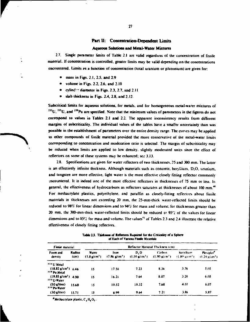
27
Pan II: Concentration-Dependent Limits Aqueous Solutions and Metal-Water Mixtures
2.7. Single parameter limits of Table 2.1 are valid regardless of the concentration of fissile material. If concentration is controlled, greater limits may be valid depending on the concentrations encountered. Limits as a function of concentration (total uranium or plutonium) are given for
• mass in Figs. 2.1, 2.5. and 2.9 • volume in Figs. 2.2, 2.6. and 2.10 • cylind r diameter in Figs. 2.3, 2.7, and 2.11 • slab thickness in Figs. 2.4, 2.8, and 2.12.
Subcritkal limits for aqueous solutions, for metals, and for homogeneous metal-wafer mixtures of 2 J 5 U, I J 3 U, and 2 W P u arc specified. Note that the minimum values of parameters in the figures do not correspond to values in Tables 2.1 and 2.2. The apparent inconsistency results from different margins of subcriticality. The individual values of the tables have a smaller uncertainty than was possible in the establishment of parameters over the entire density range. The curves may be applied to other compounds of fissile material provided the more conservative of the metal-water limits corresponding to concentration and moderation ratio is selected. The margin of subcriticality may be reduced when limits are applied to low density, slightly moderated units since the effect of reflectors on some of these systems may be enhanced; sec 3.13.
2.8. Specifications arc given for water reflectors of two thicknesses. 25 and 300 mm. The latter is an effectively infinite thickness. Although materials such as concrete, beryllium, D;0. uranium, and tungsten are more effective, light water is the most effective closely fitting reflector commonly .•ncountered. It is indeed one of the most effective reflectors in thicknesses cf 75 mm or less. In general, the effectiveness of hydrocarbons as reflectors saturates at thicknesses of about 100 mm,*1
For methacrylate plastics, polyethylene, and paraffin as closely-fitting reflectors about fissile materials in thicknesses not exceeding 20 mm, the 25-mm-thick water-reflected limits should be reduced to 989J for linear dimensions and to Hc/r for mass and volume; for thicknesses greater than 20 mm. the 300-mm-thick water-reflected limits should be reduced to 95 rt of the values for linear dimensions and to 85 r ; for mass and volume. The values4' of Tables 2.3 and 2.4 illustrate the relative effectiveness of closely fitting reflectors.
Tabic 2J. ThkfcncM of Reflector* Required for the Criticality of • Sphere of Each of Various h'mHe Materials
FUsiie material Reflector Material Thickne« (cm)
Form and Radius Water Iron D,0 Carbon Beryllium Pkrxi(da<" density (cm) M.0j/cm') (7.86 g/cm') (I.IOg/cm') (l.90K/om'l ilHOficm') 0,20 ([/cm')
' " U Metal (18.82 g/cm
" • P u Metal ) 6.46 15 17 56 7.23 8.36 3.76 5.05
(19.85 f/cm "'U-Water
) 4.00 15 16.21 7.64 8.07 3.20 6.05
(30 *7liier) "•Pu-Water
15.68 15 10.52 10.32 7.68 4.07 6.07
(30 (/liter) 15.71 15 8.9<) 9.64 7.21 3.86 5.87
'Methacrylate plastic, C, 11,0,.

BLANK PAGE
\

IH
10* ORNL- 9W6 7» -<M»2
T ! • ' I " ~ - i : r i ( i I 1 i '[ | | I I N I"' 1! 1 ! "T | _ L 1 1 1 1 1 M M II - 1 '1 I r - - - . _ 2SS " W g r j MUUE.UU5 SUL.U 1IUNS 01 U MtlAL-WAICK MIXIUHtS
... ^ i — . ... i ; • • — . * __ • i i ; • • —
" . • • . . __ • i
i • • •
-U , i " ; :=-.: • • : •
V : ' : . - • .
" i • • •
-U , i »;:. ::- : ;;; • •. .;:: •";• .:;: - ' . . - : •
"
" t ! i::i ::•: :::;: •Tlti • la F r * ... ™ I!!! :::: ::.; :~ : : I'll': " t ! i::i ::•: :::;: •Tlti • la F r * ... ™ I!!! :::: ::.; :~ : : I'll':
« ' '1 nit in s 3: sntt I
!tft \ii\r it:: iiii ilii if "iz " - •/: ' £
; f ; ; • « ' Hill HHI
illU HHf
M1IWfc.riB«IIMmi:™i H H I i i l f nn i j«BT !!'! '•! • '.' •f\ 'Jf .;'' at' t* M * |
-1 '• "Tt Hill HHI
illU HHf
M1IWfc.riB«IIMmi:™i
1 i 1 • i j f t . t . \ [METAL-WAT l« MIXTURES^ it > :l ; I - I f r 'rtf'l % ! - ..'! LX^fj SOLUTIONS i JT f ' ir
M fit; T ; •!*'; ;:.' • fcr fe : K'-:-. s -Ul I I I ! :::: -T
; L:: !!•! • !Pt : JI : _ " ' : ' s M ! ;\i If ^4 '. - \'r.
= Wiil ill. (ii) i* nr !?3 i-rft \'' ' l \ .' V-= Wiil ill. (ii) i* nr !?3 i-rft \'' ' l \
• = " '• : . V-
-! i ' i " ' 1 1 'Hi iil! / | • i ! ; v< ' ' ': : - r ; :
2 mi! K:; jtjl !'.[ « •
• . ' : ;
: ".. - ' I '•
2 1^ i \ \ ','••'• :::: T . ! i . ••
' M:U 1^ i \ \ .... :2! _u;%^T r 1 METAL-WATER MIXTURES
*0° M i:!fl :2! ITER R :FLEC IT I
60 40 20 10 3 I I I I
1 1.0 CM
1 0
1 *0° l •W • StS1 Sa •» • i
1 i • StS1 Sa ^^^ i f • l i l t ^
t ^ :! ~ JOO-mm-THICK i : •
5 ~ WAT t K f i t 1
.... ._._ .... .... — ..... .... ._. .... .... ._._ .... .... — ..... .... ._. .... 1 I
2 ~ M:U -i U0 2Fj SOLUTIONS
2000 1000 800 SO0 300 200 100 60 50 SO 20 16 2
~ M:U -i U0 2Fj SOLUTIONS
2000 1000 800 SO0 300 200 100 60 50 SO 20 16 .— L I I I I I I I I I I I
.—
rf-1 i ; ; : r i i i M i i m i i i i i I I i i f i n
.—
10" 10"' 2 5 10° 2 URANIUM CONCENTRATION (k« u / / )
10'
Hg. 2.1. Subcritical mass limits for individual spheres of homogeneous water-reflected and -moderated "M,U.

29
t O > OftttL-OWC TV-ltOft
i -i
3 z IT
(0
2 -
10°
T - " " T — 7—r- m • ' • ' , " 1 ITn - I - " • i ~ r • — j — —
' i i ' M l ' 1" - " I—"1 T T T m " 7 7 T - " 7 " ^c* — j — — ,23! i i . /» r » « , « - ^ ^ o^. , . T , « . . - 2 3 5 . . . . „ . . . „ . , . . - _ ,
— j — —
« v » 2 r 2 «w*ut .««a o u i - u i w n j o u n c i H i . - W H i c . i t M I X I U K C . 3 r i
! -! -- - - . - 4 - ' . ; I 1 i- - -
i - -| ... - - J
! .... •-- - - - - —
. i - -| ... - - J
! .... •-- - - - - —
..'.'. ._. :.': . I
•i - 1 i
... .
n! i! '.'.* 1 ::::: •- - " : :
- 1 i \-:
Ti !! "I f h ' I TTT n? ' \— * Mi* . .!- \— ; ' 1 V :' i _f ; '''in':- ' ' !
- • • • • • ; METAL-WATER MIXTURES
• ' •
, ' ; • 100 60 4 0 20 K> 3 1 0.4 0 : ' • ' :.l V 1 1 1 1 1 ! .: * • . V • • ' - . 1 1 1 1 1 !
^ \ Sj" • ' • ' • - -— i - s — !
• : - : - : - •'•': ^* - -— i -
—
::• J ! 5 - m m -KATER
TMI REFI
CK -EC T0» t
._ i _ ,._ j t ;
. . :r ':.- v \
! 5 - m m -KATER
TMI REFI
CK -EC T0» t
._ i _ ,._ 1—r i S0LU1
1 '10 >N! S if;-
- i r •
™ ^ T ! ; r ^/ ~""*" . J .
VK) - d i m - T M l C K ^ V WAT E-1 - 1 «FLECT0R .-=<-.-=<-
" — - - - -_.. -- __. — METAL- WATEf 1
1 MIXTU IRES ~ -
-I 1 1
H:ii F, SOLUTIONS
m n " IRES
—
2 0 0 0 IO00 8 0 0 9 0 0 3 0 0 2 0 0 100 8 0 SO 30 20 IS ... \ - |_ I I 1 I I I I I I I I ... \
i i ' ' [ ' 1 I 1 1 | 1
... \
10 10"' 2 5 10° 2 URANIUM CONCENTRATION (kg OF U/^l
10'
Fig. 2.2. Subcritical volume limits for individual spheres of homogeneous water-reflected and -moderated :"U.

E
s UJ
I c UJ o z
2 ORNI -0W0 7«-1«OS4
2 -4::. — 1 - . « •
........... , .,...,....,. |. M H • ••! )• ••.!:::.! ::l::iv:-|-:-| 1 1 . H : : • \' :•.:!... J..:J..:. 2 3 * l i r » - . F « AOUEOM3 SOI UTIONS A 2 3 9 U METAL-WATER MIXTURES '. ii- .'::• I . ( .
TTTT»
"irir
10 s ::::
c
"i :::: :~:;: Erzn ~-T.:': lz "—' E ;::: . 1 . .
:::£: fr :::: iH; "i! t* *i ,,,; ..., . : ; : • " ... , ,
TTTT»
"irir
i l 's iit ! 11! S3 !!'! ' !- !i!t .*i ?a ] ' | ; i | i ' i jrrr li;l. ;T ',!'! 1". .'!' i ! i i i i '! i',l i,il Oil W i'te • : !!!! i i i i •* > • * . : ! ;!!' ' ...! "'! " i " • r r r l U < : !... ;• "Tl -J } ' * i i • J. •!'.' •• \ • i '.it I»i • • ' • " V •J : 1 • •• H:U METAL-WATER MIXTURES
lOO 60 4 0 20 10 3 1 0.4 0 • ' ;
•
• - ' •:: 3 H:U
METAL-WATER MIXTURES lOO 60 4 0 20 10 3 1 0.4 0 5 ;;^ • :-': : ' " •
H:U METAL-WATER MIXTURES
lOO 60 4 0 20 10 3 1 0.4 0 5 ^ ; •: !!!: 25-mm-THICK WATFR RFFl FCTOf
. I I I 1 1 \ 1 1 ! ' i
• ^ y. 25-mm-THICK WATFR RFFl FCTOf * • \ 1 ~ - •>; 4 —
T n, • ' ' ! ! — sj :" QUI r-n r . • nr.
~ -• • • . . i | : : —
•!;' * ' , ' • ,
•• i i : '. :
2 -1 i''' : ;:; " ; i
Ni "
"".!.] UOj Fj auuu 11 « m ; . ; . ; • : : : i : T 1 i ! . 2
::.'. Ni " 5 7 ? ^
i i i
v : : ' • • ' ; :
r; : | ; : : H i :
....
- i " :'}:. 1
i i i
" " • • i
- • t • * I 1 t'' I < i
i n 2
- i " :'}:. ,. o w - m m - miwv WATER REFLECTOR i i i
" " • • i
- • t • * I 1 t'' I < i
io — * • *"1 £
• • i
I < i
; 1 „*" s.„ W E T A L - W A T E R M I X T U R E S • ! • s.„ ;
5 • • " ', ' 5
. . : • '..': * — — "
•
— *';• : •
— " :.: :
k t 2 r U O J F J SOLUTIONS 2000 1000 800 900 300 200 100 80 90 30 20 19
.• k t 2 r U O J F J SOLUTIONS 2000 1000 800 900 300 200 100 80 90 30 20 19
• . .
...
3H 1 1
. ' : . . ! . . .1..- 1 • 1 1 1 I I I I I I I I
_ L ' h , . i i i i | i i ! :
i n ' 3H i i ' - • • • - • , ; • H J • " ' li • • • • • ! ' - I • -v l ! rtti rl • _ L ' i l i i
10 ,-2 I0*"1 2 9 10° 2 URANIUM CONCENTRATION (kg U/4)
10'
Fig. 2,3. Subcritical dizmeter limits for individual cylinders of homogeneous water-reflcclcd and -moderated : , 5 U .
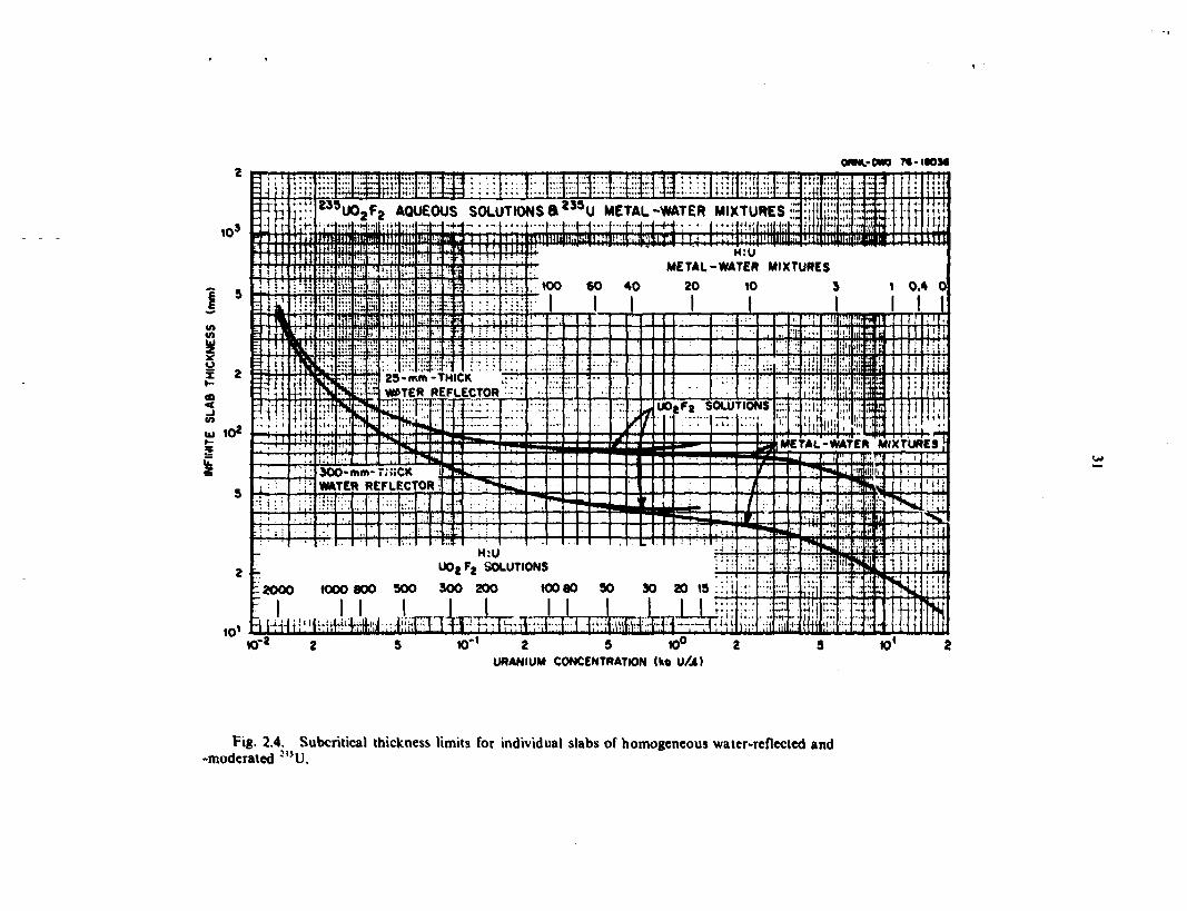
ONNL-CWO 71- IMM
x 'U0 2 F 2 AQUEOUS SOLUTIONS a " * U METAL-WATER MIXTURES
10° 1:;"f-H-± iiiliiif'WBlii
5
(A 10*
2 -tOOO 800 SCO
H:U U O J F J SOLUTIONS
500 200 10060
10' Kfa 2 5 K>*' 2 S «0° •0°
URANIUM CONCENTRATION (ho U/jt) K>'
Fig. 2.4. Subcritical thickness limits for individual slabs of homogeneous water-reflected and -moderated J M U.

2 ORNL-DWO 1%- l«09S
2
nil' -.:u\: :i::. I :t: lf::J .I H H : .1.. I. L I l:li::J f ' l 1 1 1 - : rUi-i'll. • 233 . , « 233, , L"
• : ;
""TT . . . : • ' i 11 i''! 1 ! ! ; : v u 2 ' 2
...: i « t , "4 •r* " • - • « * - T • ".:'.: ::;• 1M' • • . .
.-:- i ; u ,t*i . . . . . . . w , , .„>
ii!: 1 i
S iiii s
Iff to lis. !^i" . . i i •0 it itii '"I l'!i 'lil 7!," f i ! " HE • . , Jr ' : ( ' 3 !F. ;!• if • .-,. pi T I r" ' ' | • , / l
M'l'
i ' • | ! ' 1 | \ •
i ' i ; i i ' ; • . 1* M'l' I';'
) • • • : 1. . . : 1 • .
3 3
: : : ; ,,. \ 0 2 F 2 SOLUTIONS •Sm, : METAL-WATER 3
3 T^ "~
' 'it . • •
0 2 F 2 SOLUTIONS MIXTURES !'
9 ! ; j f c J .:.. ' ! ' . .: _^ IT; " i i n f | i : • < —
** 1! !T .' : • : l i l - i - J -• < —
$
1! !T bV: ! .
3 E.! i ! \ : ; i .1 i'li. ;; 3
E].:!! — • • • i
'::: : : : ' - .: •;! :iii i , . ' '•''.
5 = t o 0
- .. 1 - ' • ' '
23-mm-TMICK WATER REFLECTOR " t "
VI 1 . • ' . ' • I ' : • • - '
1 1 . 5 = t o 0
- .. 1 - ' • ' '
1 '* V " S u o - m m - i n i m -3 \ ^ 'WATER REFLECTOR" •• !
X 1 1 1 1 1 1 1 ^ H:U
METAL-WATER MIXTURES 100 60 40 20 10 3 1 0.4 0 I I I 1 1 1 I I I
H:U METAL-WATER MIXTURES
100 60 40 20 10 3 1 0.4 0 I I I 1 1 1 I I I
H:U METAL-WATER MIXTURES
100 60 40 20 10 3 1 0.4 0 I I I 1 1 1 I I I
H:U METAL-WATER MIXTURES
100 60 40 20 10 3 1 0.4 0 I I I 1 1 1 I I I I I I I I 1 1 1 1 1 1 1 1 1 1 1
•
• • ;
UC^Fj SOLUTIONS 2000 KX» 8 0 0 9 0 0 3 0 0 2 0 0 1 0 0 8 0 5 0 3 0 2 0 15
, : 2
UC^Fj SOLUTIONS 2000 KX» 8 0 0 9 0 0 3 0 0 2 0 0 1 0 0 8 0 5 0 3 0 2 0 15 ; , , J
4 « - <
[ I ELLLJ i 1 -1
i 1 1 i 1 1
1 1
1 1
1 1 : 1 : 1 "1
1 1 1 -,l 1
1 1
1 1 1 " •• : ; i s
1
10 - 2 10' , - l 2 3 10° URANIUM CONCENTRATION (kg U / i )
10'
Tig. 2.5. Suberitical mass limns lor individual spheres of homogeneous wulcr-rcflectcd and -moderated ' " I ' .

33
t-H-tft. "*"" MSI
UOJ^J SOLUTIONS 2000 1000 «00 500 300 200 W0«0 SO 30 20 15
ili':l:!4Jlk.1!*4i'fr:!=ia^yPHfay URANIUM CONCCNTRATION (kf U/*»
Fig. 2.6. Subcriiical volume limits for individual spheres of homogeneous water-reflected and -moderated ' 'U.

ORNl-DWO 7S-I«03<
I -K W
i
URANIUM CONCENTRATION (kg U/4)
Fig. 2.7. Subcritical diameter limits lor individual cylinders of homogeneous water-iefleeted and -moderated " l ; .

35
H' lT111MI.II»-H+WtWtf^^ O M L - O M rv-woso
' " ^ J O J F J AQUEOUS SOUJTlONSft m U METAL-WATER MIXTURES
METAL-WHEN MIXTURES •00 CO 40 20 «0 3 < Q4 0
V 5
• t i l l MM; sm: I" .» - . • -« '«; . «.> *»«MltM» Ml! * * ; - •» 1MB-!i.«- •»( •_ •|iHltt«!»liS*!ssB&• > * » * - - HU; > . T * * •»« *£« •3 t f£ * t iHB*RU>n« i — . lataeSPiMIMMBJ.
« «*ff?
id*
10'
— IKJJF, SOUITIOMS 2000 IOOO no wo MO yo too ao so » 20 is
I I I I I I I I I I I I :i::q::::|: : W T::T : 1 r t::::F:R-4 fFFffm~-
«r i0"» 2 s to 9
UPMMIUM CONCCftTftATlON (k f U / i >
Fig. 2.8. Subcritical thickness limits for individual slabs of homogeneous water-reflected and -moderated "Pu.

10
i M
v>
3 a
i 1 10
s ORNL-OW T» - l •ott
s • i 1 i 1 1 1 1 1 1 1 I I ! 1 ! 1 1 1 1 1 1 1 11 _ . . . * * V i 0 2 - WATER MIXTURES » M * P u METAL-WATER MIXTURES- - - - - - . . ...... - :
-U~.f .... 1 ...... — - - - —rt 2
-U~.f .... 1 ...... — - - - —rt 2
• ^ i • :::J .; ; *. • ' - ' \ «es .-'..
• j : ; ; ; ,,,
1 -: : ; •
', ' • " • ' . "'...... --'. ::. • : : " PuO, - WATER «
«es .-'.. W'M ::'::
1W. ' ! i ' ! ' ; • • , ' 1 ''!i , j . <
«es .-'..
tW j JlL 7 - i+Sf i-li ! • i - i+Sf i-li
"!!! :::i II^VJ S : ' i ! \y^ S . . ;
1 _ . . . ME1 r*i -Wi kTE R MIXTURES * i ;
- • ' • , ™ 1 25-mm-THICK
WATER REFLECT0A d 1 _ . . .
ME1 kTE ... y - • ' • , ™ 25-mm-THICK
WATER REFLECT0A d 1 _ . . .
ME1 ... y
• ; • • -
! •
2
• • -
• : ;.': ; ; 2 ^ :: i :
0 * * l 900-mm-THICK WATER REFLECTOR
I I I I I I I I , : !;: j P 1 I I 1 I I I I I t • i
k f c METAL-WATER MIXTURES
& iC 100 40 20 K) 3 1 0.4 C & X -+-
I I I I 1 1 — .... -- -+- i
• • • - - i-lz =F-+rrffl —
j
H:PU Pu02-WATER
....
f i
200<
" 1 MM
5
1 <( XX
1 |
>T3
1 i
|
0 S
1 00 1 1
3 00 200 1 1 II 1
too
I II 1
SO
1 Mi
SO 20
1 1 mi i '•I
10 5 0.4 0 1 I I I .— irn imrr
.....
K>" 10" I0 U 10" PLUTONIUM CONCENTRATION (kg Pu/41
l i g . 2.9. Subcri t icul mass l imi t* lor indix idi ial Npheres of homogeneous water-reflected a ml -moderated " ' "Pu.

37
Oftm—MC Tt-• • " " ' • • ! • • " H^ :—r- "T—i—r~~" T i r rm—i—r i \' = Trrr —
' . i _ -J i I I I 1 ! 1^ —
1 ' ! J 1 ! 1 ! ! 1 i l l - • — 1 s •
_ „ „ 1 s -s
k " " " P u O j MUTER M I X T U R E S • " * l > i » M E T A L - V M T C R M I X T U R E s - i
.-.._ \ 1 n - - - } - - "H~ -- . . . 1 4- — '.i .-.._ V* 1 l J - - - } - - "H~ -- . . .
. | I 4- — '.i
•;. \ w J n i _ 1 . T 1 i -t— y :: M fl !. •••-f t ( i . — , , 1 1 ; - -1 . r. 2 9 - m i - T M C K : ; NATE* HtfLECTO* : METAL-NATE* MIXTURES
v:: :::'. : " SSffl^li IOC « 0 2 0 KJ 3 • OA 0
»• .... — SSffl^li » 1 1 I I i l l »• - t * * ; - " * *«u« (uu»4 JJtlM*. «•»«.-; V - • I .; ' • . \
i .- T U t l t l l t t ' 1 " ^ ' - l " i ' ! ) i i; t I M M t U t l i f l t i ^ t i & n i i i e * . " * r M M t M B i M I M I • ~ -
. •
*fit !ul i . . •:: "*jpfn++r\ "•' [ • -
k i ! .
V • : • :): 1 T « ^ ,
_ ,-J V t r r • . : r
iiiil M r. 300—•«• -THICK . 5 BATCft HEFLCCTCM — -
, - w r = m i --H-H-—^ V - t - ' t— ftft mi !•*' "t! r" ~ 3 * 3 • ' ! - - Z>*J^, • - - r
4
- t - ' t—
•*;: ' r .... •
S V V . .'-i Z - T 7 :".:: T* ' - =*: :-.! iz. ' £ - • ' . r : ; ' : i
:••: : '.'. .1 ^ - i .v.'. "': r " ; M . ' PwOg-mHttn * 1 " ; [:
" l
W° :::: :::: ~! * :". ~: . r _ : : -"rf:'.
i
I -r
K l i e . • ' • ' •
r * * \ ! . *m • • -. :JI. • •m B _ .
: " at^\ •
'- ": ^ ^ t i '!'- . '- ": ^ ^ t i . '• ' ' • .. " \
,™j • • — —
• * , V ,™j • • — —
• * VN 2
• PuO
«:P« ,-WATCR
A 2
2000 1000 790 900 JOO ZOO WO 9 0 3 0 2 0 K> 3 0 4 0 •
• f t " '
1 i
I 1 1 1
1 n 1 I H ...:, 1
1 1 i l 1
(S 1
II 1 1 • J i
1 II
1 1 Mli i « 10"' 2 5 tO* 2
PLUTONIUM CONCCHTMATlON (Kfl Pv/4 ) »'
l-ig. 2.10. Subcritical volume limits for individual spheres of homogeneous water-reflected and -moderated '"'Pu.

2 ORML- »W0 7» - t t<»7
2
3:!i \i[ \\ 1111 1 1 1 1 II 1 1 MM M i l l - - •
1 i ' •
• i ' ' T : : r
10* 3:!i ' :;
2 W P M 0 2 - \ WATER Ml XT URE S ( * " * P u METAL-•WATER MIXTURES - - •
1 i ' •
• i ' ' T : : r
10* "Mi, . ' • ; . ... ' • . :T • *' ~~ "* *~~ LI ! • •
• ; * . • " ' ! ! i > ** ~~ "* *~~ LI . ~ " "n LI
i ~ " "n LI
6 5 E
:.- H;Pu 6 5 E i . • ' METAL-WATER MIXTURES
DIAM
ETER
<
to
T^«< • - _ . . 2! W
OC fA
, | - — - luu * u €» iu 3 ^ u,* v. 1 I I I I I
DIAM
ETER
<
to
. ._ . - . ^S
2! W
OC fA
t-mm kTER
- T H I C K REFLEC1 roR .... — ... ....
i . '
DIAM
ETER
<
to
t •
— * _ _ "3
2! W
OC fA
- T H I C K REFLEC1
. ^ . _ • ' **^^m - P u . ! i
O j - WATER " 1 1 i i - •
t •
— * _ _ "3
2! W
OC fA
i -"E
mm R f
- T IEF
HICK LECTI OR
. ^ «_-
=
. _ • ' **^^m - P u . ! i
O j - WATER " 1 1 i i - •
- P u
- _ —
- P u
^^KT* * •- — .
-
—
_ — — -
- P u
s-2*S 2
— —
— -
s-2*S 2 3
— METAL-WATER MIXTURE s-2*S 2 3 " 1 "
—
—
- • • ....
— • - - - .. .. . . .
— 2 H:Pu
_ Pu0 t -WATER 2000 1000 790 900 300 200 100 50 SO 20 10
- 1 I I I I I 1 I I I 1 3 0.4 0
I 1 1
—
.«« . 1 1 1 1 1
—
10' r* 10"' 2 5 10° PLUTONIUM CONCENTRATION (kg P u / i )
10'
&
Fig. 2.U. Subcrvtical diameter limits tor individual cylinders of homogeneous watcr-rcflcctcd and -moderated '"Pu.

39
«t ona.- DOT i * - * o « o «t , . . , , , . , . . . . . . . . '"T - C I ' I i I ; I 1 ^J^- '" '"\ i : T ~"Z1 • i . .
I f ! | 1 I 1 I • _ L ? •_• i_ T t 1 » ! t ! T 1 • > , ^ • P H O . - M A T E * MIXTURES • " • * » • METAL-MATER MIXTIMES ! _ "" !' t 7 f J J ; |
1 •
__L J j t . . . . j ~t 1 ' -T ! I . . . . j ~t 1 ' -
: : I E 1 1 | • \ !
„
:;:k j H- • • 1 {• \
! 1 : •
-f "%J :.: B-Mt-THICK • H E R MCFIECTI e*: : . . . H:fti
METAL-attTEft MBTUMCS •00 40 » «0 3 « 04 C 1 i l l I I I •O* TT
TT
• •
• j
*-**tllE- SS3L-. *
H:fti METAL-attTEft MBTUMCS
•00 40 » «0 3 « 04 C 1 i l l I I I
•s * l«Ml l l t l l l» . . <• ~ .MS. u,. .. • • l U U W 1 I J ' ' I f •' | tHl lMUiMmWi. . •'"UBi^JW f • - i • — • 1.*' * ~ " ' • ' 111 • II": £ XIXI • U l J!K t^mm^i •. i .
- j **Oi- rnn*~ 2 •• : : . " £i -i • n r r TH '
_ s
- j **Oi- rnn*~
' l :U i • ! • : r r _ s •
' : ; : : ;:•:! ! • ! . 90O -mm-TmCK T .
i i • [ i:i i :-f: *
! .
: : ! : "!* ; !
! . r-? ".: " r - : - — — T ~ ^ ' • : ^ ! .
3 : : : ":. ™ " [ : : .' "' ! ™ - ' i i t
5 « ' ::':': ; - ' ... | : :;• I -
• ^X 5 « ' J - » ' »»!! "i r HC TAJ -«UTF« •HgTuTcM t»iK i 1
. 1
" ' f
" •
• • . I • i !
' + •• . j . _ 4 . . _ •
- -1 ., ' + •• . j . _ 4 . . _ r - -
T r - - + •
ufi
2000 fOOO 790 SO0 3<
1 i l l •ri i mi rni
X) 200 1 1 71 1
•
H:Pw * i 0 j - « A T I
00 90
1 1 I I I 1
X
1 1.1
» 20 1
II 1 0 1
9
r i n 11 0.4 0 1 1 iU. I
«r* 10"' 2 S tfi Z PLUTONIUM C0*CCMTA*TI©* (kf Pv/l)
10»
Fig. 2 .12. Subcri t ical thickness limits for indiv idual slabs of homogeneous water-reflected and -moderated ; " P u .

40
Table 2.4. Clitic* Spherical Facile Material Ridii with IS-cm-Tfckk Reflectors
Sphere radius (cm» (-rsnle nutcrul
fotm and denuty Water Mg/cm')
Iron (7.86 g/cm')
D,0 (I.10g/cm')
Carbon I-Wg/on')
Beryllium (1.80 g/cm')
PlexigUs* 11 JO g/cm')
' • ' U Metal (18.82 g/cm'l
• " h i Metal 646 6.53 5.90 6.04 5.02 6.19
'•'U-Water 4.00 4.u2 3.80 3.83 3.32 3.87
(SOg/bter) '••Pu-Water
15.68 15.28 14.96 14.2? 12.13 15.23
OOc/bter) 15.71 15.08 14.86 14.17 12.00 15.22
"Metbacrylatc plastic, C, H , 0 , .
2.9. Limits given for 25-mm-thick water reflectors generally provide a sufficient margin of subcrilicality to compensate for water jackets about piping and for reflection by concrete 300 mm or more distant. Limiu for a 300-mnvthick water refleaor are appropriate when reflector conditions cannot be rigidly controlled.
2.10. The reactivity of a slab of fissiie material is more sensitive to reflector conditions than is that of other geometries. Unless the effect of a reflector is known to be no greater than that of water, the slab limit should not be used. The limits for the two reflector thicknesser can be averaged when the 25 mm thickness is on one side and the 300 mm thickness on the other.
Slightly Enriched Uranium « 5 wt % 2 , 5U) 2.11. Application of the limits of Table 2.1 and Figs. 2.1 through 2.4 to uranium containing
5 wt % V or less would result in safe but very uneconomic criteria. Strict administrative controls tc establish the enrichment and to maintain material identification are mandatory in order to take advantage of realistic limits for uranium of low enrichment. Further, criticality is not possible for unmoderated uranium containing less than approximately 5 wt % " 5U.
2.12. The critical mass of uranium enriched in J " t ' to 6 wt <7r or less is lower for a heterogeneous system than for a homogeneous system; i.c., the minimum critical mass of a lattice of rods in water is less than that of an aqueous solution containing uranium of 'he same enrichment. Therefore, limits arc greater for the homogeneous materials. However, if the particles constituting a mixture are uniformly distributed and are larger than 127 microns (i.e.. not capable of being passed through a 120-mcsh screen), the mixture must be considered as heterogeneous *l4\
2.13. It may be possible to make natural uranium metal rods critical in water if they are of the appropriate diameter and spacing. The minimum : , , U enrichment of critical homogeneous aqueous mixtures is about 1%. Calculations44 made by a validated method4 established the following limits
41
on the ""' I' enrichment of several materials that will be subcritical in homogeneous aqueous mixtur.s or solutions regardless of the values of all oth*r controlled parameters:
Limiting enrichment Material <w» Tc :"U)
VO, 0.97 VO, 0.96 V 0.94 UO.<NO,): 1.94
2.14. Subcritical limits on masses and dimensions of U « 5 ) * metal and oxide rods of any diameter or latticing in water surrounded by a thick water reflector have been calculated/1 Thrse limits can be applied to other heterogeneous arrangements of uranium in water. Since the reactivity of a heterogeneous array depends on the surface-to-volume ratio of the uranium pieces and their spacing, limits derived for rods of optimum diameter latticed at the most reactive spacing are applicable to other sizes, shapes, or distributions. Experiments4*'47 indicate that a random arrangement is less reactive than is a uniform array of rods at optimum spacing; the actual spacings in a random array may be distributed about the most reactive spacing. Subcritical limits for uranium and uranium dioxide in heterogeneous mixtures45 are given in Figs. 2.13 through 2.17. The limits are applicable regardless of the size or shape of the metal or oxide pieces; they also apply if the environment of an aggregation of pieces does not return neutrons to the system more effectively than does a contiguous water reflector (see Tables 2.3 and 2.4). Subcritical limits for homogeneous oxide-water mixtures*5 are also given in Figs. 2.13 through 2.17. These limits are conservative for solutions of uranium salts and particularly for nitrate solutions because of the lower uranium density in the solute compared with UOj and because of neutron absorption by nitrogen.
•Read as uranium enriched to less than or equal to 5 wt % in 2 , 5 U.

42
»» ORNL-OWG 76-IB041
10'
X a 2 z < 10 J
I 0 2
10'
• • r 1 * f 1
; i i t
300-mm-ThlCK v - > - - ! - > •
t
300-mm-ThlCK v — U WTER REFLECTOR ,
—t- _f... _.. \ i
r 1 ' I T 1 j [ j
: i i II :. I ! III ; ! !
11 ' i . .: . ; . .... , i .. • -— .11 1 HOMOGENEOUS UOj-HjO
™±JI.\------[--• j 1 4 \ L 1 _ ,
:. \\ \ 1 ! 1 Al I ' ' 1 i\\ \ \ W \ "
•
,. . "^ - • --.-----\ y \ • • , - - - • • -
. . . - | -- , V ....... i
i \ \ T J
\ \ T \ \ T
f ^ S ^ - \ . T
— ! —
t ' . HETEROGENEOUS METAL - ^ " ^ X S w
- - i — i . —
I I —r" :::-\\:'.\ : : .'.
~ \ ~ . t • '. i. — : ) • : • ! ; • : ~ \ ~ . t • '. i.
< 2 3 2 3 S U INHKANIUM (wl %)
Fig. 2.13. Subcritical mass limits for individual spheres of water-reflected and -moderated U(s$ 5).

43
10* 0«NL-OWG T«-<804Z
1 i i 8 \ i 8
6 < i - m m - T M I C ER REFLEC1
6 i ' 300 - m m - T M I C
ER REFLEC1 K
4 i j WAT
- m m - T M I C ER REFLEC1 roR
4 - - • - ; - ri - - - - - f - — I " i •
: LL_L_,—:_ J_ -_4„— 2
LL_L_,—:_ J_ -_4„— 2
- : 1 . i ! . .. I 0 S II 1
: : .
11 ! e \\ e 11 e U i 1 e
V ' 1 4 11 | i 4 _.._\ , — ....... 1 -
i f
1 . 2
f : t t 2
\ V \ M0 M°GENE0US UOj-HjO
I 0 2
\ \ \ •: •:
. . i . I 0 2
• • \ " \ i \
6 \ . \ f \ _ — -it ! EKOOtNtvAJi UXIUE 6 \ ^ ^ X ' " i
6 :\ ^ \ ' ' 6 :' \ NJ i 4
1 k\ X. ! ;
4 I \Vi .Xi --! \Vi .Xi --2 TT+- ""I" " f --^s^j^^ 2
: :.: ' !" '
i HETEROGENEOUS METALT""-^^
i n '
:• . 1 ; . . . . . . i •
! ' :
2 3 4 2 S i U IN URANIUM {»t %)
Fig. 2.14. Subcritical volume limits for individual spheres of water-reflected and -moderated U « 5).
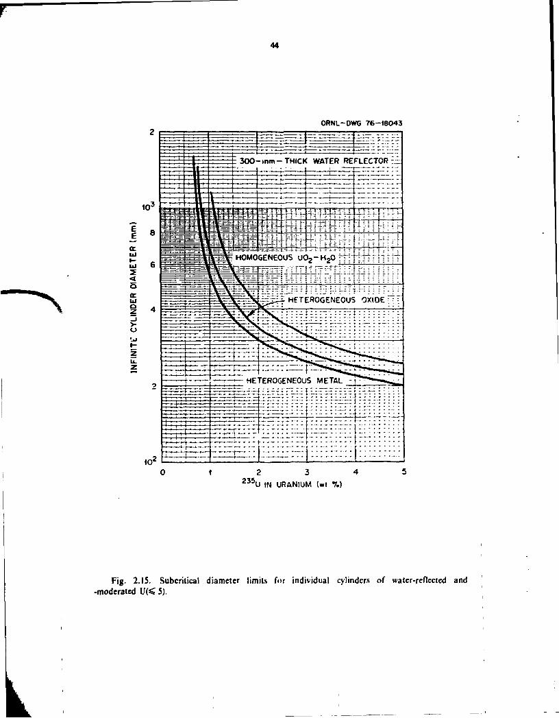
44
ORNL-OWG 76-18043
ztz 3 0 0 - t n m - T H I C K WATER REFLECTOR ZLZ.
TT-rrr-r:
10<
rrtrr
-H-n
HETEROGENEOUS METAL -f
m* .^,—,_.
2 3 4 2 3 5 U IN URANIUM (wt %)
Fig. 2.IS. Subcritical diameter limits for individual cylinders of water-reflected and -moderated U « 5).

45
ORNL-DWG 76-18044
2 3 4 2 3 5 U IN URANIUM (wf %)
Fig. 2.16. U(^ 5).
Subcritical thickness limits for individual slabs of water-reflected and -moderated

oftNL-CHK re-taots
nrr r t r 300-mm-THICK 4 stiH-irri-r rr'-i l A l \ i W*TER REFLECTOR I|f = 4 i l i u i l i i l I
1 2 3 4 " 5 U IN URANIUM twl%)
Fig. 2.17. Subcritical areal density limits for individual water-reflected and -moderated units of U(s£ 5).
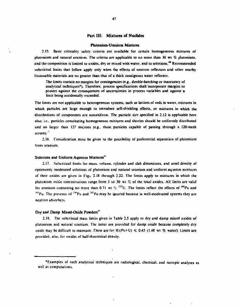
47
Part III: Mixtures of Nuclides
Plutonium-Uranium Mixtures 2. IS. Basic criticality safety criteria are available for certain homogeneous mixtures of
plutonium and natural uranium. The criteria are applicable to no more than 30 wt % plutonium, and the composition is limited to oxides, dry or mixed with water, and to solutions.4* Recommended subcritical limits that follow apply only when the effects of neutron reflectors and other nearby fissionable materials are no greater than that of a thick contiguous water reflector.
The limits contain no margins for contingencies (e.g.. double-batching or inaccuracy of analytical techniques*). Therefore, process specifications shall incorporate margins to protect against the consequences of uncertainties in process variables and against a limit being accidentally exceeded.
The limits are not applicable to heterogeneous systems, such as lattices of rods in water, mixtures in which particles are large enough to introduce self-shielding effects, or mixtures in which the distributions of components are nonuniform. The particle size specified in 2.12 is applicable here also: i.e.. particles constituting homogeneous mixtures and slurries should be uniformly distributed and no larger than 127 microns (e.g.. those particles capable of passing through a 120-mesh screen). '
2.16. Consideration must be given to the possibility of preferential separation of plutonium from uranium.
Solutions and Uniform Aqueous Mixtures43
2.17. Subcritical limits for mass, volume, cylinder and slab dimensions, and areal density of optimumly moderated solutions of plutonium and natural uranium and uniform aqueous mixtures of their oxides are given in Figs. 2.18 through 2.22. The limits apply to mixtures in which the plutonium oxide concentrations range from 3 to 30 wt % of the total oxides. All limits are valid for uranium containing no more than 0.71 wt v/(, : 5 5 U. The limits reflect the effects of 2 4 0 Pu and : 4 l Pu. The presence of : ,*Pu and 2 4 : Pu may be ignored because in well-moderated systems they arc neutron absorbers.
Dry and Damp Mixed-Oxide Powders49
2.18. The subcritical mass limits given in Table 2.5 apply to dry and damp mixed oxides of piutonium and natural uranium. The latter are provided for damp oxide because completely dry oxide may be difficult to maintain. These are for H:(Pu+U) ^ 0.45 (1.48 wt % water). Limits are provided, also, for oxides of half-theoretical density.
•Examples of such analytical techniques are radiological, chemical, and isotopic analyses as well as computations.

48
OKML-IMS 77-4S7M 100
80
60
40
O 20
•
«? Q.
o <n B in < 2 6
o K 4 X a
. • • p • ~ — i
• im »-T» T "" " —: zzz: 1 • * » * ' • • . : I . - r ^ *li: ? : - : •k - - • \ r- : ;;: :-:- i : - k l
L v s
': N \ .... • : -
': N \ ... • •
• : -
T- -f _ _ > '. • : = • '• ~ ^ : T- -f v \ . - i -•
**" N s.._. \u - i -•
\ i \ V :\:\ • ' • : : :
: .!.:
: ; ;
\ A, ^ : : ::;: -'.'::: i« '.'. 7. u
: : .'.'.'. s
V :::: .:::: ::;:. ^f.' * ! ! ' ? " • : ' ' v • x , . 1
'yl'1 '1' IT!! !'!|| ' -\ 5_ .tl. , • • • """ \ \ , \ ;•:' =: -U T . T
• V; 1 V i •
J_^_- ' \ | : u> .^ L" '.:.. J_^_-: \ : : ! - l \ '. t • •• : - V : •• ~ ~ i : ! ;
1 "• .> :':'. •:: i i -PLUT0NIUM ISOTOPIC COM POSITION \ " "=: i •
_ 2 4 0 P u * M , P u v 1
M0p„ 2 is « | % ANO M , P u S 6 w t % ; • ^ .": ..: . M0p„ 2 is « | % ANO M , P u S 6 w t % ; . '".'.
"•" L_
24<
L >P«
L L. 25 w
J - L ANO
ill M , P u i 1
11 5wl
; • •
- t
.1 . • ;
4 6 8 K> 20 wl % Of Pu02 W Pu0 2 • U0 2
40 60 80 400
Fig. 2.18. Subcritical mass limits for water-reflected individual spheres of aqueous homogeneous mixtures of PuOi and U(0.7)O:. The small quantities of "Pu and ''Pu expected in these isotopic mixtures are considered to have a negligible effect on the limits.

49
oftm-ms rc-t«03t
I "
10'
I ™ • • j • T T .,.-.- T rr ~ T' •* "
1 • . ; !' I _ __l ' .: -i
• • • "- -1 ; : _ ^ ; i - : - .:. •::: -
\ ' • • : ! . : : .:.; - "1 •k
. . 1 . '•: : : • ::: -" _
^ N : ! • : : : . _
^ „ " • . ' •: ': ; • ..
x — '^s *' »« 3""**" ^ " ^
-vLi * • i :: ~
x — '^s *' »« 3""**" ^ " ^ ; . > * - - ..:: ;••
——- — .::: ; •
——- — +< . . . j
• : • : { • : • : .: - :::' '" .«. „
.Tj* **r» I ' • ] • j -u « • i . : j ; ^ ^ S i : • ':*: -'
= ' .!!= " = • • _i 1 } ;=. -. :: = :• i . - • : ! . : .
• ' • •
—— PLUTONIUM ISOTOPIC C0MPOSITON
| **°P» * 2 4 , Pu
.-' ;;• :'... ' • : .-—— PLUTONIUM ISOTOPIC C0MPOSITON
| **°P» * 2 4 , Pu • .- : —— PLUTONIUM ISOTOPIC C0MPOSITON
| **°P» * 2 4 , Pu :":
Z 4 0 P u I 15 »t %ANO M , P u S 6 « l % • " ~ 7 * w P u S 2 S » t % A N 0 " " P u S ' S i r t * - . . . •
i * : . . : :::: :. ; • . "-
1
I 1 V ... .
KP 5 10' 2 • i % o r PuOj * Pu0 2 • u o ?
I©*
Fig. 2.19. Subcritical volume limits for water-reflected individual spheres of aqueous homogeneous mixtures of PuOj and U(0.7)Oj. The small quantities of : , , Pu and M : Pu expected in these isotopic mixtures are considered to have a negligible effect on the limits.
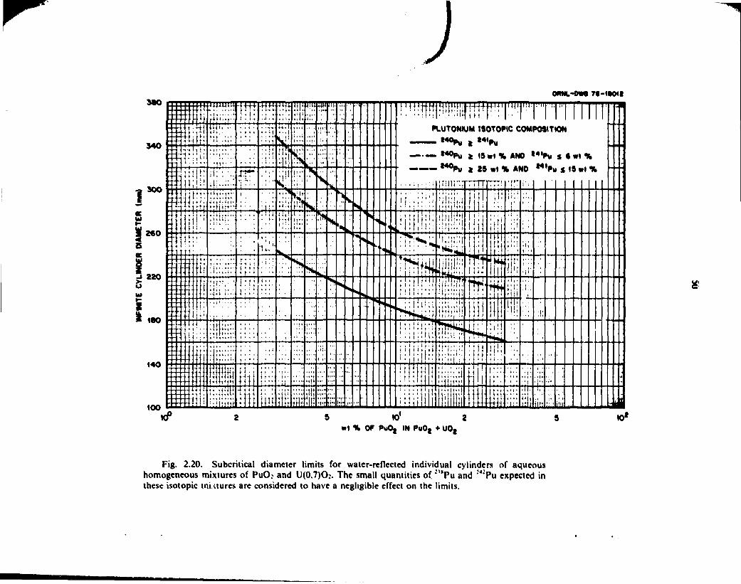
0*M.-MM 7«-t»01t M O
540
1 300
S
[
2«0
220
leo
140
too
• • x *rrrn -J-H-IUJU Hi-
44U . - i 4-*
TTTC
lit: TO rrr ' " TTt!-w THTO 1W nTTT mr i;*n
! • " '
: : | | i t i i \lu::y.-Hi-44U
. - i 4-*
TTTC
lit: TO rrr ' " TTt!-
' ' ! ; i : ' : - " ' i ! ' ? i i i Y •]• \ 1 1 1 1 1 1 1 1 • - t - ] M ' : - ;H; » - * ; * i.i:i
•••! |- i .
".' PLUTONIUM ISOTOPIC COMPOSITION MOpu t M , P M
::.lr.!i!:::i;:i.-. : : i ; i u:! • " •
•::: : • ; ' ': v — .—. MOp^ j 15W» % ANO M , P g s • wt %
M O - . — M l - . ._ . —
L iJUp i i ; : : - , I f f : : ' " ! ' ; • *
i • . . 1 — P U
TTTTpTT! : f j ' , Pll s f 3 W! Tfc
:::^fr.:}J::iji- i
i i<-':? * - 1 ' , ,1,;
*4' s :
, - ~ ^ -
• • • * . i ;i};:ji:i Pi! :! ; i i ! •
i • i >
;:: i iTii j i ' i i i" -1 -le
1 ! ' •
1 !! 1 J "
s S :•. S * ^ i i i i i l i i : ilii|!!| ill ,W •
— t ' • : : \ • i i : 1 ''X :Tr!"K^'t.:!i!:i tt 111 ill • ' 1 1
: |?i- : . | ! ; ; ; ! : ; : : : i * t •
i • •
^ 1 M'liUT m IT? -1*4 iij! i l 1 !
1 ' • '
'j : : : : : j ; ' I r v ; i i t J
* * * ':: : i : i i i i j |
i i i i i i 1 ! -| I I . M l .
;ij::i:i! ttri' i - . , ! '
" i i : :::
'tit • ::::f.j!ii i l i:.: i i t J * * *
':: : i : i i i i j | i i i i i i 1 ! -
| I I . M l .
;ij::i:i! ttri' i - . , ! '
" i i : :::
'tit • . . , . . ( i i . . . "•; . . : . • * » « J . • i <
j i ;
i l <
|Jj) iii
iijiji i ' 1 ! * i!li ;!!
» * ( • ' * • 1 i * 1 * •
::-• i i : : : r.tjtr-'.- i * ', '. : i : : • • . t •
t • i t *
j i ;
i l <
|Jj) iii liiiir? -UIL nil
• ' :
— - - i t ' ij*!'"i- ::: ' • •
: : ; • •
,.: j i i l ! : I! I
HI 1'
il'iiij:: . . i . . i . , | . ' -Ml. ,
;i!i I!1: :'.' • •
: : : : i . i t i1 itlu; •Hit .... ..: " • T ... .... i j | j j 1 < 1 ' . ' .
iiiiiri: 7 ^ .in t •
• < * t '.;{: ,;;. • :•! " ' i
; ---if-ft P F l TT ll '! ft •Hit .... ..: " • T ... .... i j | j j 1 < 1 ' . ' .
iiiiiri: 7 ^ .in t •
• < * t '.;{: ,;;. • :•! " ' i
;
1+414 • -i- i iiii i till •It' i i M l * iiilL iii liiiiili III): Pii iiii :ir iiu iu " " T I L 1 ;;iii;iii iiii i till •It' i i M l * iiilL iii liiiiili III): Pii iiii :ir iiu iu
10° wl % OF PuO, IN PuO, • UO,
K>«
Fig. 2.20. Subcritical diameter limits for water-reflected individual cylinders of aqueous homogeneous mixtures of PuO: and U(0.7)O:. The small quantities of : ,*Pu and ''4JPu expected in these isotopic mi (tures are considered to have a negligible effect on the limits.

Si
f . • r i'iM'' w r m m P = - s — . = - ~ 3SP " ' < J g
J - , .
-.
-r
If"2
: i i t
- * 2 * f-31 o»
~ 8 8 z r
1 J - , .
-.
-r
If"2
: i i t
- * 2 * f-31 o»
~ 8 8 z r
' J - , .
-.
-r
If"2
: i i t
- * 2 * f-31 o»
~ 8 8 z r
-J - , .
-.
-r
If"2
: i i t
- * 2 * f-31 o»
~ 8 8 z r
;
J - , .
-.
-r
If"2
: i i t
- * 2 * f-31 o»
~ 8 8 z r
:
J - , .
-.
-r
If"2
: i i t
- * 2 * f-31 o»
~ 8 8 z r
": =
J - , .
-.
-r
If"2
: i i t
- * 2 * f-31 o»
~ 8 8 z r
.._:.-- - : - , ' : • " I T -IT_
J - , .
-.
-r
If"2
: i i t
- * 2 * f-31 o»
~ 8 8 z r
1== "H : ' :~- -S%i
J - , .
-.
-r
If"2
: i i t
- * 2 * f-31 o»
~ 8 8 z r
f?h- ' : "-j ~X-~zzr. • = ~
J - , .
-.
-r
If"2
: i i t
- * 2 * f-31 o»
~ 8 8 z r
• : • ;-?f -i-v ;.- ! - ~ 1§? = 5
J - , .
-.
-r
If"2
: i i t
- * 2 * f-31 o»
~ 8 8 z r i ~
_-.br = ~~ 1 -fcrrrig
--__r_
~++ri
- - - 1 -V i i 7
J - , .
-.
-r
If"2
£ 2 2 S . 2 M M
Hit • D A «
^ 1 1
* r •A -N 1
i ~
_-.br = ~~ 1 -fcrrrig
--__r_
~++ri
J - , .
-.
-r
If"2
£ 2 2 S . 2 M M
Hit • D A «
^ 1 1
M -
i i i -
:~rr.
i-__r
* -TT-j-^
[•• n , -r——
^
J - , .
-.
-r
If"2
I i i l
"-~ :
-Z__y
— i m - . . i
l ; '. • ' l i 1 V zzzz
J - , .
-.
-r
If"2
I i i l
"-~ :
-Z__y
— i m V zzzz
•* ' / ^ — 1 -
• . / w / - • '
> / . : ! • ' f / / " • •
- V / '• / : / / • l / . • r - : " '.. : .= t * ?•'• ' z: F f - '• : r ;
i : • ; •!- : : ; z? . "•: ' ,{/ - • ' j ••:.-; : r - r
' • ' •• - -- i ^ ; ' . : ' • ' : ' t _ T : : . * - ; • • i±Sz T?7i r l ^ :i.:-' "i? £ i : . ' ~ 'A t\-\ :Jji r : : ' ~_L" r^. - 3 ^ i-'-i:
r - ; ": f ' ' I TH'S z~y~ r • L r -?.f^ •'.'rr-~ :H i i # c =
fei •yr-~ : L - .•-":; £: f : : ; ' ; ^ * •::.:dj zr.x~r. gs
^ • - i £\ ! # '. "i. T_I '-:. . r'i '.'.''. _* . -11-r-H ~ L r
i i i i
*: i r-* r" » • ' • " • '• ::f~ ,-r- :':'r. -; '". " - : : . • : ' " : - ::._: -n:: T^t
| r ^ r • ; * .'.'.' '..::: • r ; :rri zV.-t r.:. . T : ~ : ^ i
?'.: fl f r - -•
'"•i: :.; r , :
:r-'-"£: r*i. . lil-h :BH: : : : ". • .f-S: -sfcri ^ 7 ^
?'.: fl f r - -•
'"•i: :.; r , :
:r-'-"£: r*i. . lil-h :BH: : : : ". • .f-S: • 3 ^ 5f~
If I f T-*-t-T r-r w r-T
r;-t;
bid
-~, - J
i t ± 1 t r t r EHr. m
- f - T - * - , -1 M
I I ! § 5 * " (will $S3NM»H1 9VTS 31MIJNI
3 °2

€1
QNMHM6 TO-WON
5 KT 2 wt % OF Pu02 IN Pu02 +U0 2
Fig. 2.22. Subvritical areal density limits for water-reflected individual units of aqueous homogeneous mixtures of PuOj and U(0.7)O:. The small quantities of JI"Pu and u l Pu expected in these isotopic mixtures are considered to have a negligible effect on the limits.
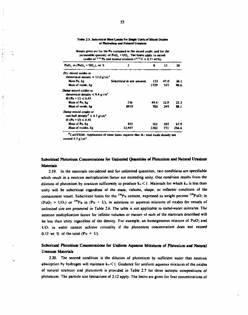
53
Table IS. Sobcritk* M M Louts foe Siagle Units of Mixed Oxides of PtokMUaa and Natural Uranium
Masses grren are for the Pu contained in the mixed oxide, and for the permissible quantity of PuOj • UO : . The limits apply to mixed
oxides of * " Pu and natural uranium (*' * U < 0.71 wt%).
PuO, in(PuO 1 + U 0 a ) . « t ' J 3 8 15 30
Dry mixed oxides at theoretical density < 1 LOg/cm'
Mass Pu, kg Subcritical m any amount 122 47 JO 26.1 Mass of oxide, kg - 1729 355 98 A
Damp mixed oxides at theoretical density < 9.4 g/cm' H:(Pu • U) < 0.45
Mass of Pu, kg 236 49.4 32.9 23.3 Mass of oxide, kg 8919 700 249 88.1
Damp mixed oxides at one-half density" < 4.7 g/cm* H:(fti + U)< 0.45
Mass of Pu. kg 855 161 102 67.9 Mau of oxides, kg 33,447 2282 771 256.6
'CAUTION: Application of these limits requires that ill.- total oxide density not exceed 4.7 g/em 1.
Subcritical Plutonium Concentrations for Unlimited Quantities of Plutonium and Natural Uranium Materials
2.19. In the materials considered and for unlimited quantities, two conditions are specifiable which result in a neutron multiplication factor not exceeding unity. One condition results from the dilution of plutonium by uranium sufficiently to produce k-< I. Materials for which k» is less than unity will be subcritical regardless of the mass, volume, shape, or reflector condition of the containment vessel. Subcritical limits for the "'Pu content, expressed as weight percent "*PuOi in (PuO: + UO:) or J,*Pu in (Pu + U), in solutions or aqueous mixtures of oxides for vessels of unlimited size are presented in Table 2.6. The table is not applicable to metal-water mixtures. The neutron multiplication factor for infinite volumes or masses of each of the materials described will be less than unity regardless of the density. For example, an homogeneous mixture of PuO: and UO: in water cannot achieve criticality if the plutonium concentration does not exceed 0.13 wt % of the total (Pu + U).
Subcritical Plutonium Concentrations for Vnifom Aqueous Mixutures of Plutonium and Natural Uranium Materials
2.20. The second condition is the dilution of plutonium by sufficient water that neutron absorption by hydrogen will maintain k .< I. Guidance for uniform aqueous mixtures of the oxides of natural uranium and plutonium is provided in Table 2.7 for three isotopic compositions of plutonium. The particle size limitations of 2.12 apply. The limits are given for four concentrations of

54
Table 2.6. Subcriticai Concentration Limit* for * " Pu in Mixtures of Plutoonui and Natural
Uranium of Unlimited Mass
Concentration, Materials Pu/(Pu + U)
(wt%)
Dry oxides. H: (Pu + U) = 0 4.4 Damp oxides. H: (Pu + U) « 0.4 1.8 Oxides in water 0.13 Nitrate solutions 0.6S
plutonium expressed as weight perceni PuCh in the oxides and are specified for each of three controllable parameters. These parameters are: the mass of plutonium per unit volume, the minimum H:Pu atomic ratio, and the mass of both oxides per unit volume. When there is less than 3 wt % Pu0 2 in the oxides, the subcritical limit of 6.8 g Pu/8 in Table 2.7 must be reduced to offset the " 5 U in natural uranium which becomes relatively more important at the lower plutonium content. For example, at 0.13 wt %, the limit is 4.9 g Pu/8. Oxides having compositions between 0.13 and 3 wt % Pu0 2 must be treated as special cases. If the plutonium content of the oxides is less than 0.13 wt %, criticality is not possible, as noted in Table 2.6. Alternately, subcriticality is ensured in the plutonium concentration range if the H:Pu atomic ratio is the controlling parameter and the ratio is r.<H less than 3780 regardless of the composition of the mixture. The limits of Table 2.7 are applicable n aqueous solutions of soluble compounds of "*Pu in (Pu + U), for example, as nitrates.
Table 2.7. Limiting SuScriCal Concentritioiu of Unlimited Volume* of Uniform Aqueous Mixtures* of PuO, andUO, ( " * U<0.7l wl%)
PuO. in (PuO, • UO,K w i * " ' 3' 8 IS 30 Plutonium isotonic
compos.t,on ' » '» » » " ' ' " »" ' » »»
H:Pu atom ratio 3780 3203 2780 3780 3210 2790 3780 3237 2818 3780 3253 2848 Pu concentration*, til 6.« 8.06 9.27 6.9 8.19 9.43 7.0 8.16 9.39 7.0 8.12 9.32 (PuO, + UO,>
concentration, g// 257 305 351 97.8 116 134 52.9 61.7 71.0 26.5 30.7 35.2 Plutonium isotopic ( „^ > U l p u
composition: II "*Po W IS wl f and *"Pu < 6 « l ?
Ill '"Pu > 25 « % and "'Pa < " wi %
'These limits also apply to solutions of plutonium and natural uranium compound* provided >'l specified conditions are satisfied. "For plutonium content less than 3 wt %, see 1 2.20.
33
Mixtures of " 3U, Carbon, and Water with 2 MTh 2.21. Subcritical limits are provided in Figs. 2.23 through 2.30 for homogeneous mixtures of
2 3 3U and 2 3 2Th oxides with various amounts of carbon and water4* Included are limits for water-reflected spherical masses and radii of infinite cylinders as a function of 2 3 3U density for the various mixtures of 233UOi, carbon, and water with Th0 2 at Th:U ratios of 0. 1. and 4. As is evident from these figures, the critical mass and cylinder radius are significantly increased by the addition of either carbon or thorium as diluents, the effect being dependent on the quantity of water in the mixture.
U3U-Water-Graphhe Mixtures 2.22. The initial effect of adding a neutron moderator (e.g., hydrogen, deuterium, or carbon)
to fissile metal is that of a diluent requiring an increase in the mass to maintain criticality. Further addition of moderator, however, reduces the neutron energy, and with increasing volume fraction of moderating diluent the critical mass is characteristically reduced. As the volume fraction of moderator is increased without limit, the critical mass typically passes through a minimum value and thereafter increases rapidly, becoming unbounded at some asymptotic value of the fissile material density. Calculated subcritical limits41 for 11(93.5) metal-water-graphite mixtures are given in Table 2.8 for selected compositions and the two indicated reflector conditions. These systems correspond to a calculzed kcrr of 0.95 and should be applied with due consideration to possible contingencies in operations. The tremendous moderating power of water when added to a mixture of U(93.S) and graphite should be noted. The critical mass can drop precipitously with the addition of small amounts of water.

56
ORNL-DWG 76-18017 10'
3 n to
'K>1
in in < Z 2 z <
• < .
o cc UJ X a. CO
<0U
«0
— i l l TT 1 iq: .- i "[•"TT-iq ( — 1 j - H — ^ — H i -- r* 1 1 I [
= 23.9 i : p -C:U = 46 [ j -r~7 C:U = 23.9 r~_L
•1 ! -C:U = 46 \. 1 J-i- l T r t r • r ' ' i i
• IOOS u \ M \ j J ? C : U = : V » T
1 • 111 l - l - - c:u= • IOOS u \
S Q V 1. r i I i '4 • ' • h i ' |—r- S Q V Strf C:l)=0 f£ . i i h [ • ' l . SKkjX! ill : | -h - • | •
:" I li >^Ni! : • • : • • ;
~r #""i« fF - T T •f ' ( - ^ ~ " fn ! ' ul !v [ ™ • i * -P> . * 1 1
-H:U»3 I - I - J - .
' 1 i t ;
! •
. * 1 1
-H:U»3 I - I - J - . • L/i t
• i i i i s^ \H-M* 2 n i l 1 ! 1 1 / ' i ^ ^ • ' A '•iM'i T -• i i ~»
! h ' f 1 t ,'•-:-:]•.. i '•iM'i T -• i i ~» , M i j (•• '' H:U*10 '•iM'i T -• i i ~»
; ; i " . r — * ' • / \t / r\: -'• H:U06 - f M •
; ! • i : f
1 A| y XI ... J- - M
f • } t
r
1 "TIT •+• / V5j M t—h - r - - k- —
' • i^ rfwr M kT l T . U - W J
; • 1 | L < r\ <««ay ' F t~ i__v^£t iv . 1 { i
! W f f f l V H S J = 300 J i .1 -H.-U=600 u ^ »111 n i ! T -H.-U=600 PH'H-^nn T~> J_ I rr f rr — r j f~
1 T ^ j j-•: ;
r - Ji- - • - •:-. : : : - l - : - '. . : : •t
1 -j :•[:•:••; T '1' ~:r. " - - ! • : ;
.'.. • r rr1
- • f 10_ «o-
233 10"
U DENSITY (g/cm') to'
Fig. 2.23. Subcritical mass limits for water-reflected individual spheres of homogeneous 3UOr^arbon mixtures containing various amounts of water.
57
«na 0RNL-0WG T6 -«80I9 «na
> ' . 1 •
I 1
5 : T ! 5
1 - - — — — I - - — — — 1
E E 3 2 o
: :u - ioo ••. • .
E 3 2 o '•'':'
—: 13 C:t - 4 6 1 •'•
(E . . . I —: —- ' S^C: J - 2 3 . ! . :.
(E
*A ^ H-(J= f.nr\.*-
*A X*
>- *A v^ i H:U = 50C > ^ j _ — • ' C:u— 0T1
i 5
u.
t ! I ~H:U = 300 r* __ S i 5
u. . j i
i M:U = 100 H : U = 3 0
1: ~~ rr
^ Z
*i - .... _ j~ .._ - _- -j — — ... " ... — - - - | H:U»I 0 - ...' 1: U-3J rr • • • • • - --- 1 — - — I 1
2 i
• • • • • - --- — - — I 1 2
i 1 i i
—
i n <
. —
1 1 m
Iff , 2 10" 2 3 3 U DENSITY (g /em 3 )
10 u 10'
Fig. 2.24. Subcritical radial limits for water-reflected individual cylinders of homogeneous UO:-carbon mixtures.

58
ORNL-DWG 7 6 - 1 8 0 2 4
K>*
10'
">
< a. 3
"10° K UJ z a.
10
J-^-q pn cp -H4H rp I r- r - r x |f I i I 1 1 1 ± h f r i ,'i ;' 1- ' "T s • 1 T r ' r
! • • ! = • V LL l i ' I L I i-.ih :U=*4
-. _.. — "~ . 11 1
• ! • • - :- -~> F m i r : . - : -:U=*4 -. _.. — :J L iJ - i II
i 1 I t 1 i j - i • - r" r • > /si v fc rh:U= = 1 : f 1 » » _t fc rh:U= XT
- i ' •- - ! • t ~~t 1 J i i i _ R r • J V I V ^ V , T h : U = 0 " !:-.- • >r r l H! "[ > r #- ^L *! U Jl
-i~" i v\\.\W ; f L >* -* # • wu 1
• • • It : t : H 1 : \ O - r t - - ~ntr * -+- h ~ \ !—i f—I 1 • • i i ; t I 1
| i ! t \ ± J i ^ 11 IP
3 • 1- ! 1 ! I | ! _L i i i jr} r 11 IP i ] ; M ( r i T L r J ^ ^ o'l_
If r 11 IP rr
> ' F \ • o'l_ If Ji'-E' I j t : "1" o'l_ If Ji'-E' 1 i | 1 i \ ± o'l_ If ^. T
'• 1 r r t » ~g T • "jwT i' . • > ! ; 1 Ki : i •> / A i o « --•; - ' ; • ^- 11 •
- 3 . . T
' •Hii-- i ! « i / I 1 X:.-3 :
; *_ • • • •
- r If i f 1 ! f l^>^
I IV
-t
oo? i l l x " r f X ; •' I
IV
-too
?
* 11 * j ' i ; i ' ^ i * ^ . • ^ I
IV
-too
?
111 J :...! L i j
I IV
-t
oo?
"t 111 I I
H ; U = 6 0 0 « ft" H*j \ • i [ I .! t ( • • • i •; ! 1 S i i : A T i \ i T* i • r !
l - i - I 3 — = >
i J i
i f i ; • ; .1 l - i - I
3 — = >
i J i
! , i n t •! ! M M l - i - I
3 — = >
i J i • \ 1 • 1 1
t T ! ' i • '•.
l - i - I 3 — = >
i J i : ! i 1 .! f : 1 I . r r (
• \-,n\ it 1 ^ 1 : : ill • T
l i i !
li to' ,-2 10"' K)°
2 3 3 U DENSITY (g/cm 3) 10'
Fig. 2.25. Subcritical mass limits for water-reflected individual spheres of homogeneous 2 " U 0 2 and "'Thd mixtures.

59
OHM.-MS TS-WOCS
10 «r' 2 2 3 3 0 OCNSlTY
5 t»/em»)
Fig. 2.26. Subcritical radial limits for water-reflected individual cylinders of homogeneous " 5 U 0 2 and 2 ! 2ThOj mixtures.

60
ORNL-OWG 76-18026
2 w (ft 4
2 o Z 4 C
- I 4
Ul X &
I r • \ ! |"H""T~^~ •;i i 1 M M + • f—1~ — i — -i- ^ _ L : : I t ! . 1 1 1 1 1' i 1 ! ' ! 1 I 1 W- ^M 1 ' - 7 5 9
4 J [ ; - U • U| r-n - 7 5 9 J I 1 T t i 1 i : 1 . f ' • r j :£=sKLC:U=H.9_i__ i | | r i i i r
[C:U«0 | 1 1 ' - C i i i r
[C:U«0 t ! i ^ ( j r " * T *^fff i i r
[C:U«0 •' j f ! t<i£ ; : i i : x5v r ii
10' j '; i . r 41 /1. H:U«0 ; r i t j 10' i , T S.TT-" :H:U=1 —\— - T - - H i 1 --L-NJ '•XL. :H:U=1
—r— —L— -*-: - t - i - 1 — 'jf~?f i 1 . —• i i i .
! j j l X I ! n\ / \ f * - H : U » 3 L L 1 _ j i ^ L_ . . 1 1 '-H-7 1 i T t 7 L H - I I '-H-7
• i ! 30 : t > j 30 t
'• I j X i
Iff f
_ j _ J - r ! T r-r / ,
I. I ..:':-"T~T r r
- i ; - + ^ * l i : u " i v u - 4 -J . I ; , H:u«*fino
<T i !. 1 1
( t I <T * ' H .U -300 1 'Zl t ; j - t - 1 : U - 5 0 0 J r r —H : U - 5 0 0 J
t I _ L • r : f ' ~i :
i i | 1 i •
i f ' 1 : • • t
.n« i | 1 ' 1 _ i _ • ; r
K>" 10' ,-l WP 10' 2 3 3 U DENSITY (g/em*)
Fig. 2.27. Subcritical mass limits for water-reflected individual spheres of homogeneous •"UO2, " : Th0 2 , carbon, and water mixtures with Th:U=l.

61
OrtNL-OWG 77-15729 K>3
E e in 3 5 <
IO<
z u. z
10'
"rr — - r T : • • •
' • *" f . • r
* • . • .. : i
j ( -; : • ±
i C:U'73.9
d : : :" .'
—; f\ L:U • l t . 9 ^ ^ ™
^* H:U«tmu~ ! f 1
r - P - - ^ ^ S c7 —r-"" T H:U-500 ' | | H ' U * l n r > J -t <:U« 30 u • M * in _ 11 I f
1
^ H - j - 3 o o i -t <:U«
1 I t 1 i 1 ^JHiU'O I -f- ._f.. - , r H- t _ _i i Ly.
H-.u-yr | f l H:U . 1 ....
1 ! i H;U»Z
i ! i i
t 1 1
; * . • !
- . _ , 10" 10"
2 3 5 U DENSITY (g /«M 5 ) ro° 10'
Fig. 2.28. Subcritical radial limits for water-reflected individual cylinders of homogeneous ""UO:. : , :ThO;. carbon, and water mix -res with Th:U=l.

62
ORNL-fMG 7C-ISOW
233, U DENSITY ( g ^ r o 3 )
Fig. 2.29. Subcritical mass limits for water-reflected individual spheres of homogeneous 'UO:, : ' : ThO-. carbon, and water mixtures with Th:Li=4.
63
\o3 OANL-OWC 7C-M020
£ E
2 2
o z >-u
IO 2 -
10'
T l * —r I J ! ! I ! { \ i
I 1 i t ! t •-I 1
1 t I 1 1 1
•-
"I' . -. - -L. t * - - — - 1 1
j "I' . -. - ?C:U"1ZZ.I3 - - — - 1 1
j r— !
7| -- — I -r— ;•
i | 7| -- — I -
j 1 i —
i \
v^ C:U-Z1.6 i ..- - -
i ! : ! .]/ —
i \
v^ r^5vC:U-o|
..- - -i
: !
• ^
• ^ ^ ^ ^ ^ a f-Vl > H : U - 0 - -» • ^
— I i: /•
f-Vl > H : U - 0 - -1 • ^
— I i: /• » H : U - 1 -
i :U • 2 !
-
, i •1:1) • 50C \' H:U • ^ ; — r H : U « iOi o-^ — I i: /• 3 0 lV~v,
» H : U - 1 -i
:U • 2 ! — • r
! , • - i —
/•
_L ^H- .U- IO
i
— • r
'! - f - . ! i 1 - [ '
— 1 4
i i
• r
'!
.... t . — - • - 1 ' - f -I
i i
• r
i i
i : .
i
i
1 i
i J i_J
! i
i i i
! - 4 -
j -
L
10 10 ,-• " 3 U DENSITY ( g / c m s )
10 u 10'
Fig. 2.30. Subcritical radial limits for water-reflected individual cylinders of homogeneous :"UO.-. i :ThO:. carbon, and water mixtures with Th:L'=4.

r 64
.a z
II I
V
7.
O N
I
IS > -
-?1?
oo — *-• O «••«»*-, oq r»
^ r-, «B « * - ; G « « « ^ <e
f ' . ff\ OO «*l M — r — r- e>
O* r» o* * N C ao — **v **i — « SO - X V) **• «o » x r* #*-. **+ — — r*
•-» r* O O - q ^ x r- r i * d
s*s
ON ON O - »
.© oc • » o •» <•-.•£ * r i - ; * n i f t ff OB r* «
r - » © — «r> ^D ^^ 00 ' ^ ^9 ^' « - 6 «i *n c «r — \0
ON — «w «•% »/>, ^ VI r ; O <•!
« ^ oe ^ o O; -O •O «r( «n 00 « ' t » « « • • «*« «•* " i
•0* «n r» o © « r> n go 0 j Nt> — NO ON © - « n m o o
>o © r* ON oo •n <-< »• ON * ON Ov - 3 —
« t c o o » 0 M » O
4 - o o < n r ~
M © — •» © O r~ — »-v ©
e. so
3
30
« z
• 3
I
IS
S-S
2 e
3 X
NO s o NO • »
O •» — o
•O 90 00 00 5
*•-. r~ o <n n
c &• >»% ON X
II
* ^ « r » r - i r t —, f . C O — **•» A ^ f^ <*© *n © t - rt o « 3J ^ °°. "} * t ~ *> ^ ° * *"**** P *n si d — ^» *** * * i « " ^ ^ > o d ^ *** v> V */i •*•• ^" f n n n • - M n ^ »*v •* •-• r* — «f »*i n n ^
^ <**> o * < n
O r- X f , — <> ~ ~
*-l © c * f*> 0* *f © O
33§!
**4 •* -T
* c* od <-*, * * i —
Nfl O *> ^ ^ «-% OO OC " » ^ t r-* c *> — od •*% w> **V *">* e * \
r* n v> n o> «9 vj « -^ ^> #*v ad» — v i r» »/i r* r- — r-
OC 00 <£ 00 00 © r~ r * i/* —• * » t 6 r i r* »o ^ v ««
S o » ~ © GO r ~ « o M >
o « —
8 © o oi — 6
© r- r-
© I- © © <N W * » — © o° © o o o
© — v> 00 ©
— ON © ™ <rt l/> 0 0 00 v% ON
S M ON ON «% ,c "> *» o->
VN «•<
© IO !•» » C M n O < t r« -^ f* «M - • — — © © © © © 6 © ©
© r- 0» «o © • « « e»
~ — ON m
3 1 ' 0 0 3 1 ' NO r*\ 0 0
r- v^ ON r* r oo o> 0 0 b NO r^
uran
iu
NO 0 0 ON # 0 m uran
iu
© v ON 1— f-V c r 00 00 f t « r< c
3
^ I n 1- © r» >r> «* ^ — ON •o oo r^ 5 -*n rsi «"N| ^ 5 © © o o O s O O o © © iil s
•w 1 © © ON r* ro * 1
*•> r*. rt CNI NC *
k

65
Part IV: Special Geometries
Annular Cylinders 2.23. Solutions of fissile material may be stored in annuli formed by two coaxial cylinders in
which a neutron absorber has been incorporated.2 Presented in Table 2.9 are widths of annuli acceptable for the storage of aqueous solutions of each of the three fissile isotopes at any concentration, provided the inner cylinder has a ^ 0.5-mm-thick cadmium liner and is filled with water, the width of the anuulus may be formed by any combination of inner and outer radii. There is is no restriction on solution height.
Table 2.9. Maximum Annular Thkfcnea for Subcritkal Aqueous SohitiOBs
o f Funk Materials of Aay Concentration
hxternal witer relVi tur Annul.ii thickness" <mm> :hickncv.tmml " ' l l ' l , , U J > » P u
25 76 45 63 300 63 35 53
"inner cylinder is lined with >0.5-mm-thick cadmium and i\ tilled with hydrogencous nulcrulv
4 Cumum enriched to no more than 93 wi 'i J " U.
Pipe Intenectioni5051 •" 2.24. Transfer of aqueous solutions of fissile materials often involves intersecting and
branching pipe lines. Guidance is provided for intersections resulting in maximum reactivity for the dimensions described. Conditions are specified to allow evaluation of practical process operations. In describing pipe intersections, larger diameter pipes are usually designated as columns and those of equal or smaller diameter, branching dom the column, as arms. For the purpose of this discussion, the cross-sectional area of a column is divided into quadrants, each quadrant containing only one arm. Mutually orthogonal arms lie in a plane thai is orthogonal to the axis of the column. The point of intersection of the plane containing the arms and the axis of the column occurs at the center of a 0.5 m length of the axis defined as a "section" of the column. No other intersections occur within a section. Diameters of columns and arms resulting in subcritical configurations within a section are given in Table 2.10. No limit is imposed on the length of a column nor on the number of sections. The tabulated values are applicable to installations in spaces enclosed by concrete structural wails defining a rectangular floor area at least 2.0 m on a side. Within this floor area only one column is permitted. The specifications of Table 2.10 apply to intersections with three possible reflector conditions. I) concrete at least 300 mm from the intersection, 2) concrete adjacent to the intersection, and 3) 300-mm-thick water surrounding the column and arms. Spaces having any dimension less than 2 m or containing other vessels of fissile material require further investigation, either by experiment or by validated computational techniques, to confirm subcriticality.

00
Table 2.10. Swbcritical fie* trade Diameters for Intenecboas Coatatnint; Aqaeoni Somtiom
Sumbei of quadrants Inside diameter of columns and arms (mm* in a section
having intersecting
• " U "»PU i . i j j in a section having
intersecting Column Ann Column Arm Column Ann arms
Intersections at least 300 mm from concrete walls a in a room
1 140 140 146 146 122 122 2 124 124 131 131 110 110 2 128 120 140 126 133 82 3 115 IIS 120 120 104 104 3 128 110 140 111 114 % 4 109 109 114 113 97 97 4 114 106 120 113 114 92 4 128 100 140 106 133 71
Intersection in contact with a concrete wall in a room
1 122 122 126 126 102 102 1 128 112 140 104 114 92 2 109 109 114 114 95 95 2 114 10S 120 110 114 72 2 128 93 140 87 -3 103 103 108 108 88 88 3 111 99 140 84 114 69
Column and arms closely reflected by 300-mm-lhick water
1 120 120 120 120 100 100 2 112 112 104 104 88 88 3 99 99 92 92 80 80 4 94 94 86 86 72 72
"Minimum dimension of room is 2.0 m.
2.25. Generally, the reactivity of an intersection is dependent upon the pipe dimensions, the length of the arms, the material of construction, and the proximity of reflecting materials. The contribution of reactivity to an intersection diminishes with increasing arm length and is not significant beyond 10 arm diameters. A bank of arms terminating in a column representing an indefinite number of sections would be subcritical by the criteria of Table 2.10. The bank of pipes themselves, however, may require separate examination as a neutron interaction problem, independent of the intersections, to confirm their subcriticality.
2.26. There is sufficient margin of subcriticality in the tabulated specifications to permit multiple arms in the quadrants of a section. Extension from the single arm condition of the table is

67
effected by control of the area of intersection as defined by the total cross-sectional area of the arms in a quadrant. Two or more arms in a quadrant are allowed provided:
• the total cross-sectional area of the arms in a quadrant does not exceed the area corresponding to die tabulated diameter,
• the surfaces of adjacent arms are separated by at least 1SS mm measured on the surface of the column, and
• the region between the arms does not contain hydrogeneous materials.
An arm with its axis inclined at an angle 0 to the column i3 permitted provided the arm diameters of the table are multiplied by >/sin~0. For columns containing more than one section and one or more arms per quadrant, the arms must be so distributed that any arbitrary choice of section, i.e., arbitrary O.S m length of column, shall contain quadrants with arm diameters, or total areas of intersection, that satisfy the tabulated specifications.

CHAPTER III FACTORS AFFECTING LIMITS OF INDIVIDUAL UNITS
Typical Contingencies 3.0. The establishment of a limit for a process operation requires consideration of
contingencies that may invalidate conditions basic to stated subcritical values. Additional factors of safety may be necessary. Conversely, it may be possible to relax a limit in certain instances. The determination should be based on careful study of both normal and credible abnormal conditions. Examples4 of changes in process conditions that affect the limits for individual units are:
• A change in the intended shape or dimensions, as a result of bulging or bursting of a container, or corrosion, or of failure to meet specifications in fabrication.
• An increase in the intended mass of fissile material as the result of operational error.
• A change in the intended ratio of moderator to fissile material resulting trom: i) inaccuracies in instruments or in chemical analyses, ii) loss of moderator by evaporation or displacement, iii) addition of moderator to concentrated solutions, iv) precipitation of fissile materials from solutions.
• A change in the effectiveness of neutron absorbers resulting from: i) loss of solid absorber by corrosion, ii) loss of moderator. iii) redistribution of neutron absorber and fissile material by precipitation of one
but not the other from solution, iv) redistribution by clumping of solid neutron absorber within a matrix of
moderator or solution, v) failure to add the intended amount of neutron absorber to a solution or railure
to add it with the intended distribution, vi) loss or decrease in concentration of neutron absorber through process operation.
Extended Subcritical Limits
Reduced Density41
3.1. Single parameter subcritical mass limits for unmoderated common compounds of uranium and plutonium at theoretical density are listed in Table 3.1. The metal values of Table 2.2 are included for comparison. These limits apply to material of the density specified and may be increased by the appropriate factors for reduced density given in Fig. 3.1. Typical forms of material

BLANK PAGE
70
ORNL-0WG 76-18007
co CO < 2 <
rr u CD D CO
o z CO
< UJ EC O
z cr o u. cr o i -u <
0.1 0.2 0.5 1.0 FRACTION OF THEORETICAL OENSITY
' Fig. 3.1. i-actors l/y which subcritical mass limits for metals and unmoderated compounds of fissile materials may be increased when densities are less than theoretical.

71
Table 3.1. Densities and Subcritical Mass Limits for Some Dry Fissile Materials
1 I\M!C material Density of U, Pu, Subcritical mass limit form or compound (g/cm1) ofUorPu(kg)
, , 5 U Metal 18 8 20.1 " 5 U C a 11.1 27.0 "•uo, 108 29.6 M , u , o . 8.3 43.5 , 1 5 U F . 6 6 47.9 " 5 U F , 4.9 69.6 "'UMetal 18.6 6.7 " ' P u Metal 19.7 4.9 "•PuO, 11.4 9.0 " • P u . O , 114 9.0 "•PuF, 9.3 10.8 " •PuF 4 7.0 16.0 "'PuCI, 5.7 36.0
to which the factors for reduced density may be applied are dry metal turnings, powders, and piles of pellets. It is necessary to avoid compaction beyond the reduced density and to avoid the introduction of moisture.
Dilution of Metals41
3.2. When 2 5 5 U, " 3 U, or plutonium metal is mixed intimately with any element for which 11 S^Z^83 (from sodium to bismuth), the single-parameter subcritical limit may be increased by the appropriate factor from Fig. 3.2. The abscissa is the volume fraction of the mixture occupied by the fissile metal. The factor cannot be applied if a moderating material may be introduced into the mixture.
3.3. It is apparent that the factor for dilution may be increased beyond the range of Fig. 3.2 when the volume fraction occupied by fissile materia! is less than 0.1. Because the need for further increase <s rare, guidance is not included in this document.
Intermediate 2 " U Enrichment41
3.4. In the special case of undiluted uranium metal in which the 2 5 5 U content is less than 100 wt %, the single-parameter subcritical mass limit of Table 2.2 may be increased by the appropriate factor from Fig. 3.3; the resulting limit applies to total uranium for the U(x) material. A factor for reduced density of total uranium (not J J 5 U) from Fig. 3.1 may be applied in adJition to this enrichment factor.
3.5. The limits of Figs. 2.1 through 2.4 for aqueous homogeneous solutions of uranium reflected by 300-mm-thick water may be increased for reduced " 5 U enrichment by the allowance factors of Fig. 3.4. It is emphasized that these factors aie not applicable to the 25-mm-thick water reflector limits.

72
20 ORNL-DWG 76-16008
2
to CO <
g - l <
<* y CO
o z CO < UJ or o z
10
8
s: 4
-•"- ----- ; : ; : | : - : i : ~ — '•"•'• E
:— —
.-^-^- . T~ : : : : : : :
.... — ....
.... — — ~
\ , ; i • : - ! " : • • :::. ••y-i r: Z :' n'l ::=.: : m ~; i ISJ f :.'--\\\ii': : : : : } : , , -r: : r • = •: \:\- •til ! : : i : ;~
^-rl\ ': ; :_: '. ', - " V -• - - ( • -
. - ^ t : : f: v-r-.i i::: ~:: ~
TSij-'i' S ^ = : = :|! = = : " : V" :: : :::: :::: :z:
?~1SN v : ^ i i i i ! -. . . ':':'.: :::: :::: :::: ::::
: : : : •N " • • ' ::: :::: E
' : ' : : • ScfSir:::{"--h:-" :::: ':::: !:!! .... ::::
! ! - : : | ; i ; ; | : . : = =KjSi[:rh!:! :'•:: :::* ~.
. : : ! • • 1 : : : : ! . : : % * ^ • : . : : .''.'.'. :::: •H :~
: < • • » * o * * X ' -""U OR U • • • ' • f " - l : : : .
\
&
:::: ~:
-""U
& ~:
...i_L.n . . . . . . ' ' * " •s k .... — .... ...i_L.n . . . . . . ' ' * " •s k
.... .... ...i_L.n
^ .... ....
.tiir ; ^
^ ....
\ .tiir
..;.-,. ^ ^
....
\ .tiir
..;.-,. N SJ
\ .tiir SJ
\ .tiir
"l" "1 \ 0.1 0.2 0.4
VOLUME FRACTION OF FISSILE METAL
0.6 0.8 1.0
Fig. 3.2. Factors by which subcritical mass limits for fissile metals may be increased as a result of dilution by nonmoderating elements II < Z < 83.
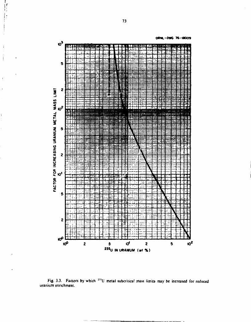
73
ORNL-OWG 76-18009
5 W' 2 2 M U IN URANIUM (wt %)
Fig. 3.3. Factors by which 2 , 5 U metal subcritical mass limits may be increased for reduced uranium enrichment.

74
- ; * » • * r * • ;
0MNL-0W6 Tf,-1fOK>
••t-^-iuh--mmm*± »##*#m*4atBam-mmafi^^sEi
5 K) 1 2 2 3 6 U IN URANIUM (wt%)
Fig. 3.4. Factor* by which the subcritical limits for aqueous homogeneous solutions of : , , U may be increased for reduced uranium enrichment, The factors apply to the solution limits of Figs. 2.1 through 2.4.

Plutonium Containing **°Pu 3.6. The subcnticat single parameter limits for aqueous solutions of plutomum may be
relaxed'0 when : 4 C Pu is present. Limits for pluionium solutions containing at least 5 wt ' i " Pu and more : J 0 Pu than \ 4 iPu. arc given in Figs 3.5 through 3.8.
Neutron Absorbers 3.7. Should the dimensions or mass not preclude criticality of the contained nuclear rr«uenal.
criticality in fissile material may be presented by the addi'.ion of cither soluble or solid neutron absorbers.
Solid Neutron Absorbers 3.8. An American National Standard. M6.4-I97I. provides guidance on the use of
borosilicate-glass raschig rings as neutron absorbers tor criticality control in plants processing fissile materials and specifies concentrations of uranium and plutonium in vessels of unlimited si/e when packed with rings.1' The recommended limits arc summarized in Table 3.2. Several examples of systems that go beyond the limits of Table 3.2. including data for pluionium-uranium solution mixtures, are discussea in Chapter 5.
Table 3.2. Maximum Concentration! of Homogeneous Solutions of Fisrile Material! in Vessels of Unlimited Size Packed with Bomsilicate-C'iUu Raschig Rings*
I issile i* .topes
M.iMimun vir.iniiiiii nr phi'..mum
i on. rntrjiion a
if UW; .>: v iUi i iu i i )
Minimum jiltw umiciii in VOM-I. v..I • 24 28 32
Uranium containing no more than 270 330 400 I w t V ' s , , U
Uranium containing more than I wt '• ' 150 180 200
Plutonium" cnntaimne - 5 wt ' . : : ) 4 °Pu 140 170 220 Plutonium* containing ' 5 wt ' ; " " P u 115 140 180
•Specilications-. The density <>t the glass shall not be less than 1.1 p/crn' .it 2 5 ' f ;md the outside diameter of the rings no greater than 38.1 mm. I he boron content of the glass shall be between 3.66 and 4.28 wt ':'• boron ( I 1.8 to 13.8 wt 'f, B , 0 , (and the atomic ratio " B : " B • 0.24. The vessel shall conform to all requirements of American National Standard N16.4 1971.
"The density of hydrogen in the solution shall be between 75 and U S d / l i u r .
*Th« plutonium shall contain at least 50 wl 'Z. ' " P u , more , 4 0 P u than " " P u , and no more than 15 wt ',', " ' Pu.
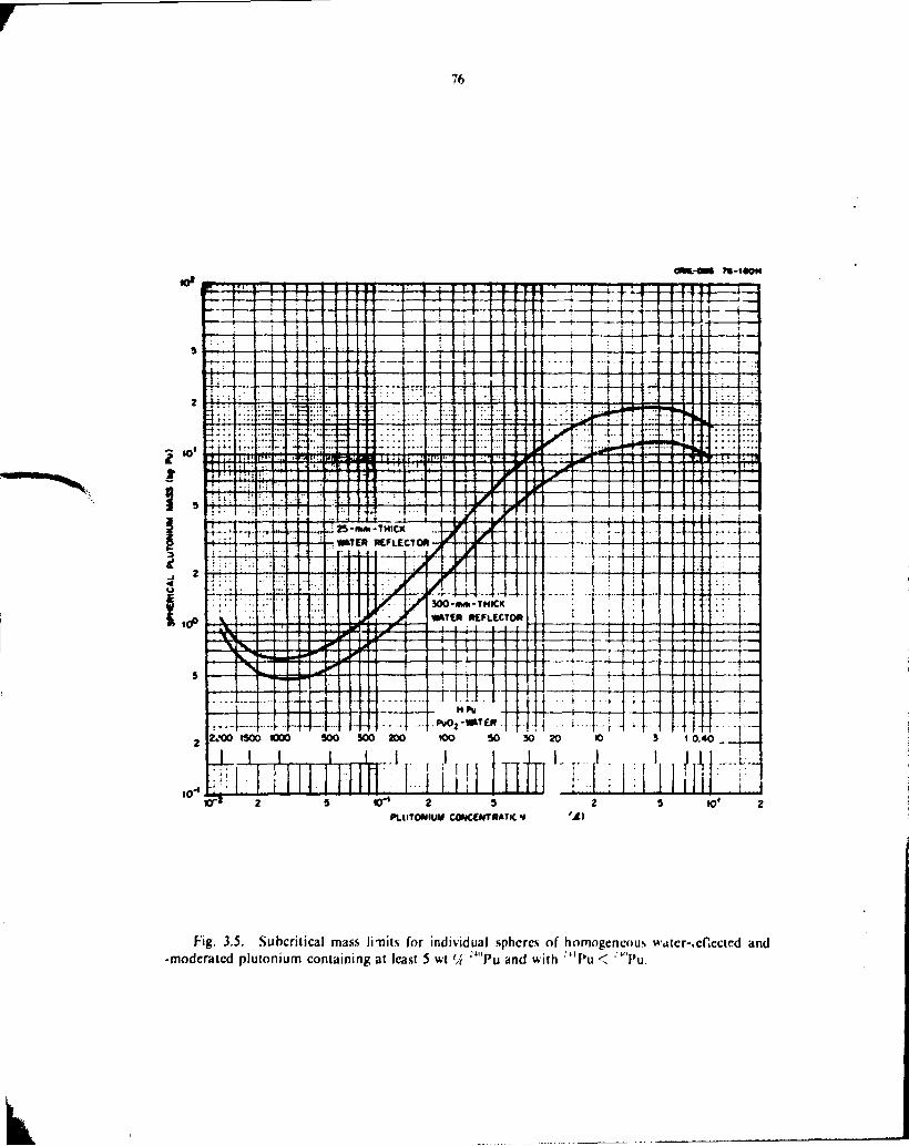
76
I 1
s
I
m* O M r am im- l«OM
f !!I " 1 ' T i r T n " ""'— " " -Z ! t ' . 1 1 — ' l ; : — ' :
5 " . — - - ... - - r -:: — - - ... - r -::
4-U- . -J - - i . •: { : • : ;:-:.: : • •
• -. ': :
-J - -• : -{ : • : ;:-:.: : • •
• -. ': :
-J - -•
"I f i : "-"- :; :; : Ji". ~ . —
' • : ' : : • -.' — —. :: ; t "I f i : "-"- :; :; :
Ji". ~ . — ' • : ' : : • -.' — —. :: ;
t
'."* ."' i ;:.-. ::.-. v^ - + • " 10' T ^ tftt T '
;:.-. ::.-. v^ - + • "
"Ttt 1 W -1 . ' i -M-r+ *t. i & — - T - t S . . •w ! ! 1 ii't L , 1 Jr I i , t r
5 ! ' •*{! • • ' " • • • • •
• • • . ' . • * . . • • i . ; 5 h- [ •4.1 • y r f
"JT|; " T • > • h - - —n J2S-" n m - T H I C K £. • - -i
. . . . . - • - . " 1 ~ • - - * ~- - — • * -
iir • • rf --- f
. - . . r - „ __ _... .— 2 iir • '-. '.: . rf --- f
. - . . r - „ __ _... ;•
.— 2
Ji:: ••' ..-; • . . : ; . : • • • : : • • • • • ' j :. ... - - ' - i • - ' • : •
10°
: : : ' • ' • ' . . : r: ir: 300-mm-TMlCK
WATER HEFUCTOR
:. ... - - ' - i ' ' ' • ' • • ' : • -
10° 1*V. ' Jr ... .1 i L i i TT^ * .[ T r TTJ \ V^ •
c* ** •tf • i f i
5 N = . 1
5 """ = . i i .... ----- .... 1 .... i
H P u - - • •
• - ' ;
? • • - »•--•
2 2**00
,1 U-1900 I
I
001
1 14 )
t 0 0
I 300 200
1 1
p u0 2 -W»T£l
OO S
1 31
. . i —
»' 20
- T T I - T -
... r .. K>
I
t-5
1 10 •40 [__.
I 0 H -ill- I , • i i l i l
31
minim •40 [__.
I 0 H
S* - » 5 B " 1 ? * 9 * m« 3 PLUTONIUM COMCENTRATIC N '.*)
Fig. 3.5. Subcritical mass linits for individual spheres of homogeneous watcr-.cficcted and -moderated plutonium containing at least 5 wt </( ' J"Pu and with "Pu < 4"Pu.

0VB fV~M0t9
<• «•. ... M l : 'i« - '
;U«UHfflmu»*«Mttt)wau£~ • •n t in iwwiaa*aaNSkvt : fe t i —*»*•«» nut an »»r* win «:* «•••.-»- n a i t a n i i
PLUTONIUM CONCCNTRATIOM ( kg P u / 4 )
{•ig. 3.6. Suhcritical volume limits for individual spheres of homogeneous water-reflected and -moderated plutonium containing at least 5 wt (% "'"'Pu and with J 'Pu < "4"Pu.

7H
o "-' -5 - - I - : : : | v : > .
. . . * -I - • . - ! " : :
i ..: . . : : : ; , a-\ - . : . : • ::.: :~ : ~ - :.. !
- i -i •
s ... ' --1 :ni J 3-j= t •
o ^
8 — _
o IZ •n
O _>; « •
8—H1
M
8_fc
i -S 1-^
^ o 1 ' - » • - [f • W 1 ' , 3-j=
t •
o ^
8 — _
o IZ •n
O _>; « •
8—H1
M
8_fc
i -S 1-^
I \- ~ _ ' • ' "
- J O r . 3-j=
t •
o ^
8 — _
o IZ •n
O _>; « •
8—H1
M
8_fc
i -S 1-^
Z ? ~ * i. - " _i . : X O - _ j
3-j= t •
o ^
8 — _
o IZ •n
O _>; « •
8—H1
M
8_fc
i -S 1-^
O ' ~~i . i C ^
3-j= t •
o ^
8 — _
o IZ •n
O _>; « •
8—H1
M
8_fc
i -S 1-^
t- u : 1 « - J / i
3-j= t •
o ^
8 — _
o IZ •n
O _>; « •
8—H1
M
8_fc
i -S 1-^
• - l « "
3-j= t •
o ^
8 — _
o IZ •n
O _>; « •
8—H1
M
8_fc
i -S 1-^
JttJiiJ^ __
3-j= t •
o ^
8 — _
o IZ •n
O _>; « •
8—H1
M
8_fc
i -S 1-^
«5i
3-j= t •
o ^
8 — _
o IZ •n
O _>; « •
8—H1
M
8_fc
i -S 1-^
i i /
3-j= t •
o ^
8 — _
o IZ •n
O _>; « •
8—H1
M
8_fc
i -S 1-^
1 I j
3-j= t •
o ^
8 — _
o IZ •n
O _>; « •
8—H1
M
8_fc
i -S 1-^
• ' i I J
3-j= t •
o ^
8 — _
o IZ •n
O _>; « •
8—H1
M
8_fc
i -S 1-^
%l 1 I 1 '•' I I
3-j= t •
o ^
8 — _
o IZ •n
O _>; « •
8—H1
M
8_fc
i -S 1-^
%l I " II
3-j= t •
o ^
8 — _
o IZ •n
O _>; « •
8—H1
M
8_fc
i -S 1-^
j t
i
3-j= t •
o ^
8 — _
o IZ •n
O _>; « •
8—H1
M
8_fc
i -S 1-^
3-j= t •
o ^
8 — _
o IZ •n
O _>; « •
8—H1
M
8_fc
i -S 1-^
& ' • '
3-j= t •
o ^
8 — _
o IZ •n
O _>; « •
8—H1
M
8_fc
i -S 1-^
<• ^ !* " "
3-j= t •
o ^
8 — _
o IZ •n
O _>; « •
8—H1
M
8_fc
i -S 1-^
z ";, ; ! •
1 ' ' 1L 1
3-j= t •
o ^
8 — _
o IZ •n
O _>; « •
8—H1
M
8_fc
i -S 1-^
z '-•:
:
£ '
3-j= t •
o ^
8 — _
o IZ •n
O _>; « •
8—H1
M
8_fc
i -S 1-^
O Z
• , . • • • <
3-j= t •
o ^
8 — _
o IZ •n
O _>; « •
8—H1
M
8_fc
i -S 1-^
o u i :
-:: :-.: ; i ; ; ' • a
3-j= t •
o ^
8 — _
o IZ •n
O _>; « •
8—H1
M
8_fc
i -S 1-^
z : ; : -•.-..:: i : : : • : :: :": ". "'.:
^ i ! I J !
3-j= t •
o ^
8 — _
o IZ •n
O _>; « •
8—H1
M
8_fc
i -S 1-^
z o
: : -. .- .... '.'.''. '.:.."" , ..... ;[;• «'&
: .;".
3-j= t •
o ^
8 — _
o IZ •n
O _>; « •
8—H1
M
8_fc
i -S 1-^
3 - a
r'i T] ' r ' l;'J T • •. :
3-j= t •
o ^
8 — _
o IZ •n
O _>; « •
8—H1
M
8_fc
i -S 1-^
^ * & % • • ' i ' J: j : rV. 1 1 . . : • ' 1 Zl'.Z- '
3-j= t •
o ^
8 — _
o IZ •n
O _>; « •
8—H1
M
8_fc
i -S 1-^
!h ' - • : ':\f . u. ~ ! UJ ""
: • .
3-j= t •
o ^
8 — _
o IZ •n
O _>; « •
8—H1
M
8_fc
i -S 1-^
:i'- ; i l ? .!:i ; . ' i . : :§?;! ' E * """"•:
3-j= t •
o ^
8 — _
o IZ •n
O _>; « •
8—H1
M
8_fc
i -S 1-^
-.-.. '•':",
:;; -~-..: ::.: If: 1 w . ^ _ • : . \ _ • .
3-j= t •
o ^
8 — _
o IZ •n
O _>; « •
8—H1
M
8_fc
i -S 1-^
¥» = ~ = r J!-! :::: L M • r Sit : : '. .-'
• ? ! '
3-j= t •
o ^
8 — _
o IZ •n
O _>; « •
8—H1
M
8_fc
i -S 1-^
¥»
liL iii Hi" i f f ; r m ; - .
3-j= t •
o ^
8 — _
o IZ •n
O _>; « •
8—H1
M
8_fc
i -S 1-^
c . ' ••;i f.WTii! .: t i 1 :! . _ y ;.r . „ . . . . ^
3-j= t •
o ^
8 — _
o IZ •n
O _>; « •
8—H1
M
8_fc
i -S 1-^
'Jr. r p" : ; ; ; ;:*? mi !£ -'
3-j= t •
o ^
8 — _
o IZ •n
O _>; « •
8—H1
M
8_fc
i -S 1-^ * ^ncr •:~ ""1:3 'ft: •u:i :t:t-' :* LTC- - • • : . : : . • • " '.:'.-' '.':
3-j= t •
o ^
8 — _
o IZ •n
O _>; « •
8—H1
M
8_fc
i -S 1-^ E : § :?:? jar:. :::-. .' Z ...
.:;
3-j= t •
o ^
8 — _
o IZ •n
O _>; « •
8—H1
M
8_fc
i -S 1-^
: : • • • ' ; '
z\ ~:~ iiil nil r ; f ; " •
• ' • • : : . ' . : .
S "" rr (0 O
1 c< ( M o f) ~ -3
•o o o t> c u ^ ^ u C3 # V . 3 3 O c-b C , o
V F 3 o a. x: o J =
b . * u - r l •n • ^ « 3
a. cs T
3 " ."2 & ** •o t c '"• ir» L - ^ o (« ns t )
E « SO C
t» c u CO
e e «3 o
"O u _ F s 3 V C u O
« -o 3 3 o r/>
« •-» r- B i ^ 4> T3
OA o U. fc
f
•o c <9
(ww) U313WVI0 U23N11A0 3J.IMJNI
L

79
H = ~ : : - .r. i • e-; • •
•.: : ' . : • ":.' " . v-i
-::: . '. '. . :::-.: i ~
~ : : - .r. i : • •
; • •
v-i
-::: . '. '. . :::-.:
i -~ ' • -
.... ."«! '„ . : .::. ::;:. _^__ ,_ . , ; ... -
. . . . i-i....--~ ' • -
.... ::;:. _^__ ,_ . , ; ... -
. . . . i-i....--~ ' • -
o 1
::;:. _^__ ,_ . , ; ... -
. . . . i-i....-
*1 !? TT ' o ,!',! ! l ' i * f • T"» : ' 'V J \ \\ *1 ft •g ~:" 5—:
h 2 —.
•
8 — l : L 3
m ^ { ; ! i ' T .'•j ' ' ' r • : :
ifi 5—:
h 2 —.
•
8 — l : L 3
.r1 = : : '. : ; ' • " \Jr ! • " f. • ' •
fi • • ' -
5—:
h 2 —.
•
8 — l : L 3
.:; ^ ' . ' : • • •
f:-. •• J • . : ft 5 ~ :r
5—:
h 2 —.
•
8 — l : L 3
r:. : : ! - : • ' / f • • • ' '..':':
" r- J
5—:
h 2 —.
•
8 — l : L 3
e i O I /•I /
. . 1 .
f l ; : ' '
5—:
h 2 —.
•
8 — l : L 3
!'" ' • ; ' _ * «-> - / - _ J ' •
• :
i ": :•'.
5—:
h 2 —.
•
8 — l : L 3
: . - y UJ - ~ / • • :
•! :
5—:
h 2 —.
•
8 — l : L 3
" I n "" *- UI / i
7 • • ' :
5—:
h 2 —.
•
8 — l : L 3
- 1 It — f J f : : ::
' - ' • : . ...
5—:
h 2 —.
•
8 — l : L 3
J • •
'..: ' . L I ; .
k _ . . . -•
5—:
h 2 —.
•
8 — l : L 3
I - • : • -k _ . . . -•
5—:
h 2 —.
•
8 — l : L 3
I 1 w*
5—:
h 2 —.
•
8 — l : L 3
I ' ' ;• M 1 h"
5—:
h 2 —.
•
8 — l : L 3 ——*—-! *- T t
• ! • \
IO L i
——*—-! *- T t
r : . "r :
UI »>
5 J ' • I - :
;'": UI »>
5 . - : ;
::•• .2 2 • i
I S -
8 -
8 -.
i -
: ' • •
• ; • •
- • . ; . :
.2 2 • i
I S -
8 -
8 -.
i -
: • ;
';,;
K -.2 2
• i
I S -
8 -
8 -.
i -
. :: • • • . •::•.-.
K -.2 2
• i
I S -
8 -
8 -.
i -
..-. • '
~:-:'
.2 2 • i
I S -
8 -
8 -.
i -
. ..\ '. \ \ '•''• i i-
I ? T
.2 2 • i
I S -
8 -
8 -.
i -
.'.l. i i i i , 1 • <• i f -
I ? T
.2 2 • i
I S -
8 -
8 -.
i -
j ! i i ! 1 ! 1 ' ! | " " j X.
o X t-1 E 6 I
8
*.!,, " \' ' • ' * !v
.2 2 • i
I S -
8 -
8 -.
i -
i ; [ • { ; l ^ I X.
o X t-1 E 6 I
8
* ? H' ;-
.2 2 • i
I S -
8 -
8 -.
i -
l ! i ! • : : 1 m X.
o X t-1 E 6 I
8
O •'.': . « : : •
.2 2 • i
I S -
8 -
8 -.
i -
ml : : ':'•' f ^. t X.
o X t-1 E 6 I
8
_l
.2 2 • i
I S -
8 -
8 -.
i -
• : • • : : \\ \ \'-. i :
X.
o X t-1 E 6 I
8
*<•:.
.2 2 • i
I S -
8 -
8 -.
i -
• : • • : : \\ \ \'-. i :
X.
o X t-1 E 6 I
8
*<•:. :n :::
.2 2 • i
I S -
8 -
8 -.
i -
\ \ i /'-•::':
X.
o X t-1 E 6 I
8
a • "
i —
.2 2 • i
I S -
8 -
8 -.
i -
= - d = */': 'J f T :;.;
X.
o X t-1 E 6 I
8 J-|! ': v:-. : J ! 1! | :
r.;.-.
.2 2 • i
I S -
8 -
8 -.
i -
^T^ I'Vri f :
X.
o X t-1 E 6 I
8 r-5 ~ !::•
.2 2 • i
I S -
8 -
8 -.
i -Hi '':- •f. i.y ri; •.'.'•;;:;
:ii':':: '::
.2 2 • i
I S -
8 -
8 -.
i -::: ::: \vj M-::: ."•:!' .' . ' : ;
= ::: 1
.2 2 • i
I S -
8 -
8 -.
i - :::: *rn;=; '~.:: . '.. . ', I~l —
:iz -»- . 8-— iC ~T *"
t i i ; .. '. .'.. >M*U M T I i[2
°o
- 2 *-z UI u z o o z
<M 3 z o »-3 _l
7 °-o
(V
•o c CS
•a u o o c: u h»
k-
u C3
* ir. . 3 3 O 1 . K : C7. u o V E o.
3 E o.
C-j = ^
<•-o £ .y. ,D S CQ c/i c
B) tU 3 3
• a c_ > T
• a
c v C
'.-• o *
>/v tf)
E 5s
— i — 3
kne SO
c u c •g 2
c «t o u •S £ t> 3
Sub C
o 3
•^r SO i » % H * r f 00 2 u. •a
o S
o o
<u>ui) SS3NWIH1 8V1S 31INIJNI

80
Soluble Neutron Absorbers 3.9. Any use of a soluble absorber for criticality prevention requires confirmation that the
absorber be uniformly distributed in the fissile solution and that it cannot precipitate. 3.10. I he concentration of gadolinium in unlimited quantities of aqueous plutonium solutions
required for k, to be less than unity have been calculated. The calculations were validated by experimental measurements."" The data of Fig. 3.9 are applicable to ; , ,Pu(NO))4 solutions of Aero acid molarity. The maximum diameter of subcritical cylinders of infinite length of PufN'O;).. solutions containing various concentrations of Gd(NOi)i are shown in Fig. 3.10.
3.11. The concentration of boron in unlimited quantities of aqueous uranium solutions required to reduce k. to be less than unity have been calculated. The calculations were validated by experiments'1 "w and calculations performed for several enrichments not exceeding 5 wt •?£ '. For any given enrichment, there will be a H:U atomic ratio that results in a maximum k*. Figure 3.11 gives the minimum B:2 , 5U atomic ratio required to result in k, less than unity for any moderation and for any , 1 l . uranium enrichment up to 5 wt %.
3.12. Calculations4"'57 indicate that the presence of one atom of boron for each atom of ~"l,' will maintain large volumes of aqueous solution subcritical for : " U concentrations less than .ton <i Ht,! A hor(ii:-!:r-2 1 1! • atomic ra!ii> -if ! 5 ss sufficient »n to a concentration of !10fi a '\\.^
Shape 3.13. Certain shapes of containers for fissile materials, such as elongated or squat cylinders,
may have the mass and container capacity limits of Chapter II increased by the appropriate factor of Fig. 3.12. The factors apply to water reflected units and do not apply to other reflector materials, e.g., mcthacrylate plastic, polyethylene, graphite, etc. Factors should not be applied to slightly moderated, low density materials with clo1-"!^ fitting reflectors, for example PuO: at a density of I g cm' and an H:Pu = 0.4. The situation may be generally described as a reflector moderating effect (see 2.7) and will require additional analysis.
Concrete 3.14. Concrete is significant in nuclear criticality safety because its effectiveness as a neutron
reflector may exceed that of water. As a consequence, it may be necessary to reduce the limits given in Chapter II. Although the composition of concrete is variable, its effectiveness as a reflector changes only slightly within the typical density range of 2.1 to 2.4 g cmJ and as the moisture content ranges from j to 10 wt %.
3.15. lor closely fitting concrete 100 mm or less in thickness, the single unit limits specified in Chapter II for thick water reflectioi y be used. This concrete thickness corresponds to a maximum of 230 kg m2 (~48 lb, ft2).
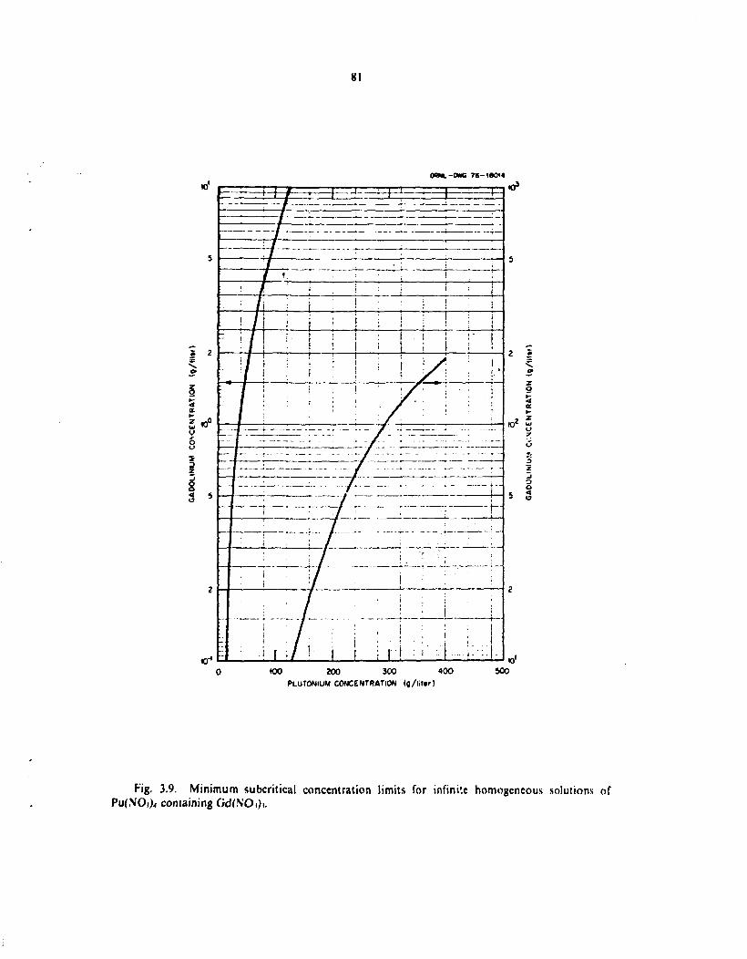
81
ORNL-MG TS-tSOM
< B Z U V o o s z
(0"
«P
— H 1 / i -f- _ j — M - * ~=—1 • 1-. .
— / - — — / - — — —
—— f f. —— : { •
J i i : ! : i
/ ; i I • ! : ! i
l / I /
r
; I . \ i 1 ; ! ~ i / : t
i f I
| ! i 1 •!•. 1 !• 1 r l
: i ! i : i y i !•
1
; i : i i ' ':/]'] ; |
7 ^ " — r . -— . — — / • * — - - • - —
7 ^ " — • -— .
- - / • • • • — — / -- - / - - — —1 / _J :.. / - - "
, , . „ , , . „
;
, ....
i
:
L.y
i
j = ;"' -
f =/i- i
i . ; [_._: [ —
z o
- 2
K » 200 300 400 PLUTONIUM CONCENTRATION (g/lilar)
500
Fig. 3.9. Minimum subcritical concentration limits for infinite homogeneous solutions of Pu(NOi)< coniaining GdfNOjK

r 82
3 > ^3 =3 >-= -o -c s " * • *
^ <VI t - « e a s X " r 1 -C
£• £• w *""
Z 5 -
RATI
*g »- -? s 01 Z .He Q l i i •£ Z at. o for
in
in
o for
inin
s 05
2 c z •? c o c o K —~ 3 T
*a! J O * 6 - « to 3 a :
• ^ a . ^ « o J oi «
o o 2 o o 2 x> •— £ - ! 5
S g (VI © . , *
~ 3 ^ . "•> O . -
t> "S C w
9(1 t» .Si •— oe »* u. S ' c
S 3
(uiui) SU30NI-U3 H10N31 3J.INI4M HOi U313MVI0 IVOIilMOflOS
L

83
a. o I o o
in K) w
CO
0.6 0RNL--DWG 7 7 - 14242
0.6 i i i i n . i h : i ! : : :
• ; (•; M i i : M : t ! | :
! j ! • ! ! ! • I • I • • M -. 1 •!•
0.5 ! i ! i i ! •;• ; 1 ! : i ! 0.5 .! M M i ! : { : 1 I f • j > ^ ; . M M • : | : • f : : ! i \i,u< • i-| ! M • . :
L-UO •
3 + H ; 0 ! j r ^ -':'-•
0.4
• . :
L-UO •
3 + H ; - . : - : •
0.4 liliiL i * I i : L r h : ^
i i M M •• / r J I ' ! : I j f
•i i ! - M y i I 1 1 •!.. •••J ;
0.3 i M l \ \ / : 1 : 1 :; S ! -0.3
! • ! • • ! - • ! • / ; • \ \-\-y : / i l - i y T .
!• t / ! | j / i i" 0.2 t : l / i . ! b f i ! I 0.2 ; • / :
! • / ' ! ' ! ' •
• • i j 7 1 • ! ] . : 1" . i [ / A i i i } :
0.1 ' "!
i d° o*<: i -0.1 " • ' — T " " 1 " '
; i j !
— i — i | i : i ;
r\ — i — | ; i 1 '••
1 2 235
3 4 U IN URANIUM (wt %)
Fig. 3.11. Boron-to-;,^U atomic ratio for subcriticalii) ol aqueous homogeneous solutions of L'0:(NOi): and of L'Oi-watcr mixtures for uranium comaininy not more than 5 wi U.

84
ORNL-DWG 77-14241
O I -
UJ U z I _l - I < tu QL < X (A
5
4
3
2
J —1 !— -"-
. - --"-
- ':r: , " -
• - : . !
- *
f 25-mm-THICK WATER REFLECTOR
-25-mm-THICK WATER REFLECTOR . ,
, i |.„|, > Srp* <«rr T- - 300-mm-THIC :K > Srp* <«rr T-
WATER REFLECTOR| > Srp*
•S i ; i
^ ;<
•S i ; ^ • ' \ '•
0.1 0.2 0 .5 1 2
HE IGHT/D IAMETER RATIO
10
Fig, 3,12. Factors by which mass and volume limits may be increased for elongated or squat cylinders. See 3.13 for limitations on use.

85
3.16. Closely fitting concrete of greater than 230 kg/m z areal density will require a reduction of the thick water reflector limits. The limits should be multiplied by the following factors:*51
• 0.90 for mass and volume, • 0.80 for diameter of infinite cylinders, and • 0Mp*"s for thickness of infinite slabs,
where p is the fissile material concentration in g/cm3. 3.17 A vessel located in a concrete cell or in the vicinity of a concrete wall is often
encountered. Guidance is available for the location and dimensions of spherical and cylindrical vessels depending on the concentration of the aqueous fisrte materials.*0 For fissile material . concentrations not exceeding 0.5 g/cm 3, the thick water reflector limits may be used provided a surface separation between the vessel and concrete walls or floor is not less than 0.5 the prescribed vessel diameter. For higher concentrations, the minimal surface separation should be 0.6 the prescribed diameter.
3.18. Spacing between a concrete reflector and the face of an extended slab does not allow relaxation of the limit for a closely fitting reflector in the absence of specific evaluation. Application of direct experimental evidence or validated computational technique is required.

87
CHAPTER IV STORAGE AND TRANSPORTATION
PARTI: Limits for Arrays
4.0. In addressing the nuclear criticality safety of fissile material storage, consideration must be given to the purpose of the storage area. It may be a service area providing temporary storage for materials in process, it may be an area for transient materials in transport, or it may be an arc.-. <ror long-term storage. Each use presents different problems. The number of units, their mass and other properties, the necessary accessibility, and the desired margin of subcriticality help to determine the spacing of materia!.
American National Standard Guide for Nuclear Criticality Safety in the Storage of F'u.ile Materials.™ NI6.5-I975, presents mass limits for spherical units of fissile materials assembled in cubic arrays reflected by thick water. The tabulated arrays have a neutron multiplication factor not exceeding 0.95. While it does not answer all questions, this Standard is directly applicable to many storage problems.
4.1. The materials to which the Standard is applicable are plutonium, aiV, and uranium containing more than 30 wt % I3*U, as metals and as wet and dry oxides. The water content of the oxides varies between about 1.4 and 40 wt % (e.g., 0.4^H:U<20).
4.2. The limits are also conservatively applicable to units not spherical in shape. Each unit is considered centered in its cell, and some guidance is provided for relaxing this requirement as well as for modifying the cell shape.
4.3. The specifications for cubic arrays are applicable to arrays of any shape because of the increased neutron leakage from noncubic arrays. The introduction of hydrogenous materials into the space between units is not provided for in the Standard; if such moderation is present, the effect must be evaluated by a validated computational technique. The effect on array reactivity due to the introduction of water, as for example from fire protection systems, is strongly dependent on the form of the fissile material and on the mass and spacing of the units. There is, however, an adequate margin in the limits to accommodate incidental moderation such as would result from enclosing the units in plastic bags that introduce no more than 10 g of polyethylene per kilogram of fissile material.
4.4. Factors for reducing the mass limits are provided for concrete-reflected arrays. The limits are reduced to 75% of their tabulated values if the concrete thickness is between 120 and 200 mm and to 60% for greater thicknesses. Criteria are presented for pairs of arrays in concrete enclosures. (Slight neutron coupling of arrays separated by 500-rnm-thick concrete has been observed experimentally.59)

BLANK PAGE \
88
4.5. Each unit of an array must remain subcritical if immersed in water. The possibility of double batching of the units in a storage cell should be considered when establishing safety limits and operating procedures. Administrative controb, limited capacity containers, and storage cell design may be useful for the prevention of double batching.
4.6. Consideration should be given to other normal and credible abnormal storage conditions that may affect array subcriticality. Typical examples* of changes in operating conditions that should be considered are:
• flooding, spraying, or otherwise supplying units or groups of units with water, oil, snow (i.e., low density water), cardboard, wood, or other moderating materials;
• the introduction of additional units or reflectors; • improper placement of units; • loss of moderator and neutron absorber between units; • collapse of a framework used to space units; • a change in the density of fissile material during storage; • the substitution of units containing more fissile material than permitted in operations as
a result of operational error or improper labeling.
Alternate Storage Criteria 4.7. The following method of criticality control for handling and storing fissile materials
represents an extension of the information in N 16.5-1975- The method is based upon the same experimental data and validated calculations'0*1 used for the Standard. The technique is applicable to single storage arrays of any shape reflected by concrete of any thickness and result in storage ar/ays having a calculated k,(( ^ 0.93.
4.8. The method consists of a systematic labeling of each fissile material container with a numeric and controlling the total numerics in a storage or process area. This is accomplished by a Criticality Indicator (CI) system and it is the basis for control of nuclear criticality.*2 The system requires that each unit be associated with a cell or container volume and assigns a CI to the container by the relation
C. = f (4.1)
where N is the total number of containers permitted in a storage array. The CI aggregate of a storage area must not exceed 100. The aggregate CI is the sum of the individual CIs, independent of the type of fissile material. All fissile materials presented for storage or handling must be suitably contained and have an assigned CI. Considerations other than criticality control may make segregated storage desirable.
4.9. In this Guide, the CI system is applied only to the units of fissile materials described in Table 4.1. This description includes the chemical and isotopic form, the density, hydrogen content, and the mass. The unit may have any shape provided it is subcritical submerged and the constraints
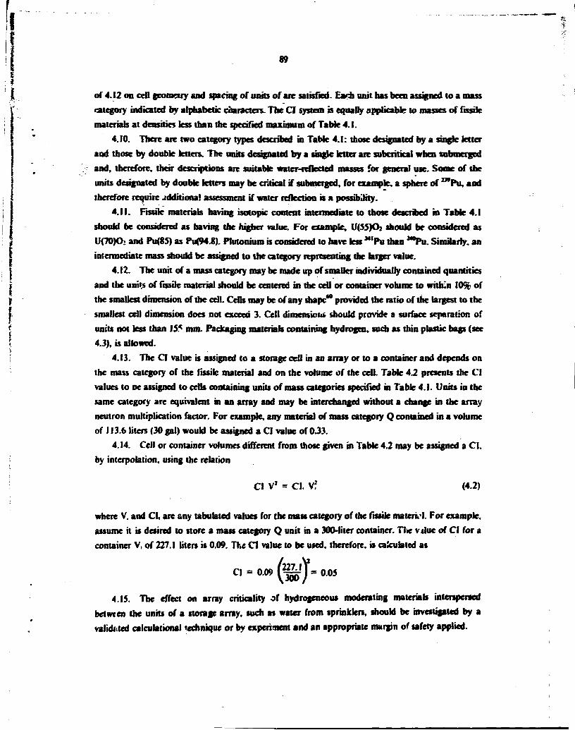
89
of 4.12 on cell geometry and spacing of units of are satisfied. Each unit has been assigned to a mass category indicated by alphabetic characters. The CI system is equally applicable to masses of fissile materials at densities less than the specified maximum of Table 4.1.
4.10. There are two category types described in Table 4.1: those designated by a single letter and those by double letters. The units designated by a single letter are subcritical when submerged and, therefore, their descriptions are suitable water-reflected masses for general use. Some of the units designated by double letters may be critical if submerged, for example, a sphere of " P u , and therefore require additional assessment if water reflection is a possibility.
4.11. Fissile materials having isotonic content intermediate to those described in Table 4.1 should be considered as having the higher value. For example, U(S5)€>2 should be considered as U(70)O: and Pu(85) as Pu(94.8). Plutonium is considered to have less M , P u than ""Pu. Similarly, an intermediate mass should be assigned to the category representing the larger value.
4.12. The unit of a mass category may be made up of smaller individually contained quantities and the units of fissile material should be centered in the ceD or container volume to within 10% of the smallest dimension of the cell. Cells may be of any shape*0 provided the ratio of the largest to the smallest cell dimension does not exceed 3. Cell dimensions should provide a surface separation of units not less than 155 mm. Packaging materials containing hydrogen, such as thin plastic bags (see 4.3), is allowed.
4.13. The CI value is assigned to a storage cell in an array or to a container and depends on the mass category of the fissile material and on the volume of the cell. Table 42 presents the CI values to oe assigned to cells containing units of mass categories specified in Table 4.1. Units in the same category are equivalent in an array and may be interchanged without a change in the array neutron multiplication factor. For example, any material of mass category Q contained in a volume of 113.6 liters (30 gal) would be assigned a CI value of 0.33.
4.14. Cell or container volumes different from those given in Table 4.2 may be assigned a CI. by interpolation, using the relation
CI V1 = CI. V? (4.2)
where V. and CI, are any tabulated values for tint mass category of the fissile match.'!. For example, assume it is desired to store a man category Q unit in a 300-liter container. The value of CI for a container V, of 227.1 liters is 0.09. The CI value to be used, therefore, is calculated as
CI - 0.09 \jfi) = 005
4.15. The effect on array criticality of hydrogeneous moderating materials interspersed between the units of a storage amy, such a* water from sprinklers, should be investigated by a validated calculational technique or by experiment and an appropriate margin of safety applied.

90
8
I I 5 I 5 $ a
i •8 8 7 3
i s i
g«s
i-s
gi«-
Co. 3 1 •
2*53?. 5552S sasss SSSSS SS333 S=?:-3S
22"25 52255 25552 55353 55533 3=3553 © • * ; — *» (h 'i « n r «— «o — >o — •>••»(
ihs
— le •« 5 ~
5 1
« !
* « q r * - - » r ^ w » * n rt • • q o. « ex » O ~ •* *> *t c «n r; " * * * * • * • » * * * " : •*v V «» vi <e N h i o » d — ci »"i •*» V «*i « «0 O* © — ci V wi * ao 0* -- f» V *
25552 2 2 ! ! ! ! 55255 52255 53555 555525
22255 22355 25555 25552 52252 522525
55555 52252 25252 22525 25555 255522 - r r 5 * ! » * t 0 * . « « x * r > r « » x » ^ o • * * r # q C* rt « •* « T T * } ^ * ^ .
— * r» — ^ * — •> O* *n to r* 00 — <e — * — <© r-i «0 ^ © 1- ^ —
2S232 52252 <« ^ © ** *n q 1^ f « » e* *> ^ m « r «o c* o* © — — r« *n *•£ V * *> r <
| r * i M D «n «o ^ o <o — r- *** o» ^ n 0 i « n » r» ft a* r» * > * / • • - • © <
*. ' I • ! ' t * l ^ " T * r t C ? n t * q » r . -<ino;mdD r# r» — * "t » ^ r * « o ^ r o *
*n r* «- w> © *r a* «x «N «* w» — r - « o » * f * c* « v ~* ex r* w «r »». -• r* n r* •* ft * V V v) *n « « r r «p c> o S 6 o - f i r««K^vvwv « r ^ o o » 6 -^
0 *> O v> O >© — r- *** «0 «nfl>wk-*r* «•» O « #n CM ** «»v © r- ^ r»
• * » — t ^ » f « v>«> — *> •t? ~ vt «o r-f «e © r aQ *n r* r* « ""!**!*•• r": *"! ^t V »l v* to »# * r- P r* •» « a* ex 6 0 - « r * r i
i2S22 22555 55555 225S2 55252 52555!
;•*••*-* w • «; « <^ • *n r- r* r» n « n o i t e* wv — *> «•* •» *; © r» *n o i p* #n #n r V V *i *> * <«) r* •*•'•»•» e* e* © © — - •» *»v »<i V V *i -^ * 1 •*
< i O O u i f c u x - - * * - J » Z O «-Ca5crtp- = > > £ < * b S S i t j f l


1
s v; : I s S * > * < " - W - ^ C T J j z ^ r r . = r. — -- c '*. a: >
C O C C O i - S « » 'v *> '— w 5 — fc — o o
— = s c o p e ?.— p - - * *J Q> 4> w w i j ^ . . 1 ^ 1 ^ Ut — ^ <0 •— i t <G ,1 -
— — o o p p o o p p o o o t J S SB » M Jk W K* ls« * * • • 1 * b © O w ao C* w ^ > o w f l e * _- oo
iS EiSSS SSSSS l as
o o * * P ? S J . i l i l S
o o o p o p ? •~> — #*» 8 S 2 S
o o o p p •= p — o — se g © © e ©
» \ » * 1 , ^ —
o o = c o c o 9* -5 2 2 £ 2
o o -- o o c e i t w o © o c s
o o o 9 9 9 ? o o © © c o = — o o o s c p p o o o o o c o p
C * ^ i ^ i j t u u i*> — -— *— O O O O w - J t - » •_: >fi O w —•" K* - J * * - * - 4 M (
— © c o o o o o p o o o o o o c o o o o o o o o o — s© * ^ «.** fc **• v * W w — — -— © © © O O O C - O © © © ©
•sj -— t * © 9 V O OB ( r Ut . £ w K* t -» » - — • - — — • J - - J V ^
— o o o o o o o o o o o — \C *<J O I A J-> *-»* Kit ls-t ~ — • •-• 'w s i 4 </i ^ ff> «© *> «9 &•
sO --J t > t * ^ W K# !--»-— •— — K* «> V . K* V * tA « ^ <0 » ' ^
Sim m i l m i l iins mi l mi l
— p © p p p © o p o o p o o o s o o o o o p o o o o p p — '-©'-.J 3* u» 1 . v * k# »•* * - — * * ' - - b K« n« 3^ •-» hi w V* >6 4t <0 O* '-* * OC
— • - > - . 9- u> I t v-> K » » j — — — — C O C O © C O O O O O O O O O
- p p p p p p p p p o p p p o p o o c o o o p p o o o p p - < ^ J l* 4t '.*> w K« i>» - - - - * - b C O O O O C O O O O b O b b O v» tx 3C •-» v. <• 3" 3 •»» © c* -< — * g u i u u . . .
— p e e p p p e e o p o p p o o o o o o o o o p o o o o o o icse ? > iul-:*.k»ij — — — C o O O O O O C O O O O C O O O O - a- oc — o — ~j «w *~ <6 ~j o* u» X w r -— •*»,» ~J :
•-» *- •—• l>» t^ — •-» •-» -. oe •*. at
C O O O O O C O O o C O O O O — — — o ' — — — o o o o o o o c o o o o - - - - - — - J < A & W * * I K f t ».; _ * _ — _ -
o o o o o © c o o © "c b b o o b s b o b
'1*
© «
o. o
— . • - * •
o» "
s *
p p -i
s • " • *
I*-I I I > 3
36
A

93
Transportation 4.16. Transport regulations*' distinguish between "undamaged''and "damaged'* packages. The
condition of an undamaged package is established by tests that simulate the effects of dropping during handling, extremes of summer heat and winter cold, and rain. The damaged package is defined by a sequence of severe tests for impact, fire, and flooding. A single package must remain subcritical when immersed in water, thus inleakage of water is assumed unless there is a specific individual demonstration before use that such inleakage cannot occur.
4.17. The storage criteria contained in NI6.5-I975 or in Tables 4.1 and 4.2 may be used to d<*rw limits applicable to Type B. Fissile Class II packages in transport. For Fissile Class II packages, the only control required is a limitation on the number of packages in a vehicle or in a storage area to a specified value, NA. The transport index (TI), assigned to a package for criticality control is equal to 50 divided by NA where the number of allowable packages satisfies both of the following requirements:*3
a. rive times the allowable number of undamaged packages are subcritical in any arrangement closely surrounded by the equivalent of an effectively infinite water reflector.
b. Twice the allowable number of damaged packages remain subcritical in any arrangement with any distribution of water that is consistent with the results of package tests.
In evaluating the requirements for a damaged package the fissile material is to bt assumed in the most reactive credible configuration consistent with the damaged condition of the package and with the chemical and physical form of the contents. Further, it is to be assumed that water moderation of the array is consistent with the damaged condition of the package and the chemical and physical form of the contents.
4.18. The water-reflected arrays described in N 16.5-1975 define acceptable mass loadings for the undamaged package. I he assignment of the TI is then determined by
where V is the tabulated number of units corresponding to the mass and cell size in \ 16.5-1975. The tabulated masses are based on theoretical densities and may be applied to materials at densities not less than 0.25 theoretical.*4 free volume in packages, allowing possible additional reduction of fissile material density in transport packages, should he discouraged.
4.19. Specifications for the transport of packaged fissile materials may be derived from the CI system since it ma> be modified to define arrays reflected by 300-mm-thick water, thereby establishing suitable fissile limits for packages in transport. The relation between a category of fissile material in storage, as given in Table 4.1. and a category in transport is given by Table 4.3. The

94
transport mass category of Table 4.3 is then used with Table 4.2 to evaluate the CI for a package. The transport index. TI. is then related to the Criticality Indicator, CI, by
TI = 2.5 CI (4.4)
Tible 4 J . Rebtioa Between Stance *ad Transport Mas Categories for Vokmes
of Fade Materiab
Storage Transport Storage Transport
A - D A S M E B T N F C U O
G.H D V P 1 E w Q J F AA R
K.l G BB S M H CC T N 1 DD U O J EE V
P.O K FF w R L GG AA
HH BB
4.20. As an illustration, use Tables 4.1 through 4.3 to assign transport indices to packages, assume the produa of an operation is a I kg quantity of Pu(80)O: containing less than 1.4 wt % moisture (i.e., H:Pu^0.4). The oxide is bagged and sealed in one-liter cans. It is desired to ship four si-ch product cans in a 208 liter (S3 gal) package having an inner container that will accommodate the four cans coaxially. The mass category of a 4 kg Pu unit as PuOi in storage is M, from Table 4.1. The mass category in transport of the* units is H, by Table 4.3. The mass category H in a 208 liter container has a CI of 0.01 by Table 4.2, and Eq. (4.4) pves TI=0.03, to be entered on the package label.
4.21. It will be necessary to analyze the damaged package cotsistent with the package test results as described in I0CFR7I, Appendix B, to determine whether (a) or (b) of 4.17 is the limiting condition.
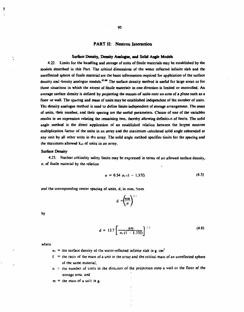
95
PART II: Neutron Interaction
Surface Density, Density Analogue, and Solid Angle Models 4.22. Limits for the handling and storage of units of fissile materials may be established by the
modek described in this Part. The critical dimensions of the water reflected infinite slab and the unreflected sphere of fissile material are the basic information required for application of the surface density and density analogue models.45"" The surface density method is useful for large areas or for those situations in which the extent of fissile materials in one direction is limited or controlled. An average surface density is defined by projecting the masses of uniu onto an area of a plane such as a floor or wall. The spacing and mass of units may be established independent of the number of units. Ths density analogue method is used to define limits independent of storage arrangement. The mass of units, their number, and their spacing are the useful parameters. Choice of one of the variables results in an expression relating the remaining two, thereby allowing definition of limits. The solid angle method is the direct application of an established relation between the largest neutron multiplication factor of the units in an array and the maximum calculated solid angle subtended at any unit by all other units in the array. The solid angle method specifies limits for the spacing and the maximum allowed kc« of units in an array.
Surface Density 4.23. Nuclear criticality safety limits may be expressed in terms of an allowed surface density,
o, of fissile material by the relation
a = 0.54 an\\ - 1.370 <4-5)
and the corresponding center spacing of units, d, in mm, from
by
where on = the surface density of the water-reflected infinite slab in g, cm2
f = the ratio of the mass of a unit in the array and the critical mass of an unreflected sphere of the same material,
n - the number of units in the direuion of the projection onto a wall or the floor of the storage area, and
m = the mass of a unit in g.

%
liquations 4.5 and 4.6 are applicable to infinite planar arrays reflected by water at least 155 mm thick or its nuclear equivalent. The reflector is located uo closer to units in the array than the boundaries of the cells associated with the units.
4.24. In th_ .«bscncc of criticality data, known consistent subcritical values such as appear in Figs. 2.1 through 2.12 may be used for guidance. For example, a unit of U(70JO: containing 5 kg of uranium at an H.I' of 12 may be established from the data for metal-water mixtures. A conservative esti nate of the unreflected critical spherical mass is the subcritical limit from .?ig. 2.1. The subcritical limit is "14 kg of uranium at an H:U = 12 (p a 2.1 g U/cm1) for a sphere reflected by a 25-mm-thick water. The com. ponding reflected slab thickness (Fig. 2.4) is 34 mm. Thus on = 7.14 g U/cm1, and f = 0.36, giving an allowed surface density (Eq. 4.5),
a = 0.54(7.14)(I - 0.49)
= 1.97 g U/cm2
Applied to two tiers in a planar arrangement, the recommended spacing, by Eq. 4.6, would be
Density Analogue 4.25. Subcritiral limits for storage arrays of any shape reflected by at least 200-mm-thick
water are defined by the following density analogue relation:
N = [ ~ ~ (I - l.37f)l V2 (4.7)
where the quantities o.P, m, and f are defined in 4.23, and
V = the cell volume occupied by a unit in the array, and N = the total number of units.
The minimum center spacing (in mm) of units in the array is given by
"-'fe^UTo]'' where n = N 1'.
Applied to 125 unir, (n = 5) of the materials in 4.24, the recommended center spacing would be
d = 10
= 572 mm
f (3)5000 I'-' 1.2.1(7.14)0 - 0.49)J
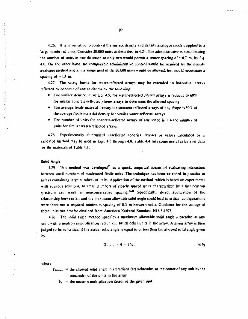
97
4.26. It is informative to contrast the surface density and density analogue models applied to a large number ot units. Consider 20.000 units as described in 4.24. The administrative control limiting the number of units in one direction to only two would permit a center spacing of —0.7 m. by Eq. 4.6. On the other hand, no comparable administrative control would be required by the density analogue method and any arrange nent of the 20.000 units would be allowed, but would necessitate a spacing of ~ 1.3 m.
4.27. The safety limits for water-reflected arrays may be extended to individual arrays reflected by concrete of any thickness by the following:
• The surface density, o. of Eq. 4.5. for water-reflected planar arrays is reduce J to 60Cj for similar concrete-reflected planar arrays to determine the allowed spacing.
• The average fissile material density for concrete-reflected arrays of any shape is 50^ of the average fissile material density for similar water-reflected arrays.
• The number of units for concrete-reflected arrays of any shape is I 4 the number of units for similar water-reflected arrays.
4.28. Experimentally determined unreflected spherical masses or values calculated by a validated method may be used in Eqs. 4.5 through 4.8. Table 4.4 lists some useful calculated data for the materials of Table 4.1.
Solid Angle 4.29. This method was developed67 as a quick, empirical means of evaluating interaction
between small numbers of moderated fissile units. The technique has been extended in practice to arrays containing large number?* of units. Application of the method, which is based on experiments with aqueous solutions, to small numbers of closely spaced units characterized by a fast neutron spectrum can result in nonconservative spacing.V>M Specifically, direct application of the relationship between k.u and the maximum allowable solid angle could lead to critical configurations were there not a required minimum spacing of 0.3 m between units. Guidance for the storage of these units can brst be obtained frorr. American National Standard NI6.5-I975.
4.30. The solid angle method specifies a maximum allowable solid angle subtended at any unit, with a neutron multiplication factor kt„, by all other units in the array A given array is then judged to be subcritical if the actual solid angle is equal to or less than the allowed solid angle given by
a„.,.,i = 9 - I0k f„ (4 9)
where n,ii„*td - the allowed solid angle in steradians (sr) subtended at the center of any unit by the
remainder of the units in the array ktn ~ the neutron multiplication factor of the given unit.

98
Table 4.4. Some Klcabted Uoreflected Spherical Critical Manet
Material Atomic ratio." Denuiy, Mass." form H L o r H P u (kg VII or kgPu/l) (kg)
U(100)Metal 0.0 18.7 45.6 U( 100)0, 0.4 8.3 81.7 U( 100)0, 3.0 4.5 57.8 U(93.2)M*uJ 0.0 18.7 52.1 U(93.2K>, 0.4 8.3 90.2 U(93.2K>, 3.0 4.5 63.5 U(80)Metal 0.0 18.7 69.8 U(80)O, 0.4 8.3 111.3 0 ( 8 0 ) 0 , 3.0 4.5 74.0 U(70)Metal 0.0 18.7 89 1 U(70K), 0.4 8.3 133.3 U(70jO, 3.0 4.5 8J.4 U(50)Metal 0.0 18.7 159.6 U(50K), 0.4 8.3 207.7 U(50)O, 3.0 4.5 112.8 li(40)Mctal 0.0 18.7 228.0 U(30)Mctal 0.0 18.7 379.7 0 ( 3 0 ) 0 , 0.4 8.3 409.6 U(30)O, 3.0 4.5 150.0 U(5JO, 3.0 4.6 494.6 Pi<(IOO)Metal 0.0 19.7 9.9 Pud 0 0 ) 0 , 0.4 8.7 26.6 Pud 00 )0 , 3.0 4.7 28.6 Pu(94.8)MeUl 0.0 19.7 10.3 Pu(94.8K>, 0.4 8.7 27.9 P J ( 9 4 . 8 ) 0 , 3.0 4.7 32.7 Pu(80)Metal 0.0 19.7 11.6 Pu(80)O, 0.4 8.7 32.1 ?u(80)O, 3.0 4.7 42.4 ' " U Metal 0.0 18.4 15.7 ' " U O , 0.4 8.2 34.4 ' J , U O , 3.0 4.5 31.6
"Total uranium or total plutonium.
The neutron multiplication factor of each unreflected unit by itself is estimated by a validated calculational technique. The following conditions must be satisfied in order to apply the method:
a. The k t ( ( of any unit shall not exceed 0.80, b. Each unit shall be subcritical when completely reflected by water, c. The minimum separation between units shall be 0.3 m, and d. The allowed solid angle shall not exceed 6 sr.
4.31. The actual solid angle between units is calculated by the methods illustrated in Figs. 4.1 and 4.2. The contribution of a unit to the solid angle at a point P is a function of its surface area and its minimum distance H to the point P. For arrays of simple identical units at uniform spacing, the interpretations of H and P are straightforward. For these arrays, P is chosen as the center of the "centermost" unit. The total solid angl* subtended at this point is, then, the sum of the contributions due to all other units in the array.

r
99
OMH-IMG 77-MM3
KMNT-TOHMW/ntARY W K
a-(Sowation) 2
•OMT-TO-CYUNOCH
LO
M y/lLm* * M*
L* Lmgih of tlM cvwfldor 0 • Damattr of tf* cyNndar
r •v-
•irtaca of «c cylMar
•OMT-TO-OffX
'~3 \ v / l + I B / M ) 2 /
•5!
R-RadkaoftAada* H-Oiatanca from tna point Plot
H n M *•» tfladiOE
•OMT-TO-VHEIIE
n - J i - J -\
R • ftadiv* of th» apnara H • Dhtanca from tha point to tha
wrfaca of tht aptw*
<£ KMHT-TO-f lANt
_ . ..r A» 1
A * LongtA of ono ofcfo of tlto plono • * Lonpjh of tho otfior *W# of tho pbno H * Pifpondicutof dMipfiGO from Iho point to
ffWF
if wo point M ofnjctly novo wo oontor of • pwno with oinionojoni 2A X 2ft (rothor mon ovor • comor m ihovm fbovoK multiply O by 4 to ODiOff* no • N W onpo.
Fig. 4.1. Solid angle approximate formulas.

OHNl-OWa 7? M»«
OFFSET CYltNOCRS
Tht M M tntjt ajbMndtd M point P by tht curvtd aurftct of tht
81-• ^ M ^
o n bo mlutwl by tuptrpotrtlon. T o * tha. tho tolid mgloi tubtondod by nMndon wMh • • « • * • X L - t X I t n d Z X a n etleulMtd n tnown bttow. TrttdtoktdtBNdanaJtkin, - O j i / } w h t r t O , andl l j i r t
... *«-£j| l * X
Thut 1 . 0 , - 0 , 1 W L * X )
M>/t l • X»* • H* HV^* * H * • contribution from do*.
ThoojHdtutJtbibMndtd by two bottom of two cyHndor o n no VMhMMd •* Ml ONMM ONfc.
OMSST PIANIS
For plan* S, ihown bttow tht wild »nt»t O, ii ar»tn t%
°S " n ( A • 01 x IC • 01 ~ ° IA • I I x C
_ [ n AX(C«OI " ° » x e ]
Ihing tht point to plant formula from Fl§. 4.1
Lv/ t* • 81* • H» v/(C • 01 s • H* J I ^/lA • SI* • H* >/(* • H» J
OMStT DISKS
PJtthtr compltx txprtwlont for tht tolid tnitt rttult whtn tht point P la not dlroctly abovt tht ctnttr of tht dltk. A oonttrvatlvt approximation for thlt of f t * OMt It to tpply tht polnt iod* formula In fit. 4.1 wrlth tht dlnanct H dtflntd « t h t porptndleular dittanet from tht point P to tht plant of tht dltk.
Fig. 4.2. Superposition application of solid angle formulas.

101
4.32. For other arrays the procedure h» similar, but ;he solid angle at each unit must be calculated and compared to die fl,i,»«j for that unit. Care must be exercised in selecting the point P for a unit of complex shape. If each total subtended solid angle is less than its respective allowed value, the array is judged subcritical.
4.33. Application of the method to other than solutions should be approached with caution. More detailed analyses'0** indicate that some large arrays of metal units spaced by the solid angle me'hod may not have an adequate margin of subcritkality.
4.34. The solid angle method should not be applied unless the following array reflector condition is satisfied:
The effectiveness of the reflector is no greater than that of a thick water reflector located at the boundary- of the array. This boundary- is no closer to the peripheral units than half the separation between unit surfaces.
Concrete reflection on three sides of the array can be shown to meet this criterion. Tor full reflection by concrete thicker than 12 cm. the allowable solid angle shall be reduced by 40%.
Other Methods 4.35. Models and methods shown to satisfy the requirements of American National Standard
N'16.9 may be used to establish nuclear criticality safety limits. It is emphasized that the concept of the method, its parameter dependence, its uncertainty in biases, and its area of applicability must be clearly understood. Appropriately, a user should document, for himself and for others, his ability to apply the method.
A method, well described and extensively correlated with the results of critical experiments, is Clark's albedo method.*9 Various tables and graphs of parameters have been published7071 which facilitate these hand calculations.

103
CHAPTER V NUCLEAR SAFETY IN PROCESSING PLANTS
Training 5.1. The training program for persons involved in operations with fissile materials should
make safety considerations, including criticality safety, an integral part of a program that provides necessary job skills and information. Safety education will be most meaningful and readily assimilated if it is clearly relevant to the operations. Therefore, it is desirabh that local supervision participate in criticality safety training. Criticality safety specialists can, of course, support supervision.
5.2. All persons working in or near a fissile material processing area should have an appreciation of the general characteristics of criticality accidents and stiouU' be familiar with t u r i r proper response to a criticality alarm or other emergency situation. Operators should also understand the influence of various parameters on the safety of these operations.
5.3. Supervisory personnel should be knowledgeable about the safety of operations for which they have responsibility. The bases for process limits should be understood in order to allow effective supervision and exercise of training responsibilities.
5.4. Criticality safety specialists who are occasionally called upon to give training talks will profit from a familiarity with those accidents ;hat have occurred during processing of fissile materials. Stratum'* has prepared a history of nuclear accidents which provides a discussion of each of these in sufficient detail to be helpful for this purpose. The use of real accident experience to illustrate criticality safety principles can help keep an audience awake (see Part III of Chapter I).
Criticality Alarms 5.5. Criticality alarms have twice initiated lifesaving evacuation of areas in which accidents
occurred. The value of such systems is therefore clear, and their installation is desirable in areas processing potentially critical quantities of fissile rrwrrials. Guidance for the design, installation, and maintenance of such systems may be obtained fron/' American National Standard Criticality Accident Alarm System, N 16.2-1969. This document directs a survey of all areas containing more than threshold quantities of material and the installation of an alarm system wherever there is a risk of accidental criticality.
5.6. The existence of an alarm system carries with it certain responsibilities. The system must be maintained to provide confidence that it will func'ion if needed and to minimize the frequency of false alarms. False alarms introduce a potential for injury as a result of precipitous response and tend to destroy confidence in the system. Personnel must be educated to their proper response to the alarm, including evacuation routes and designated assembly points. Emergency plan* must be kept current, specifying procedures to be followed in the event of an alarm.

BLANK PAGE

104
5.7. The Standard recommends that the response of the alarm system to radiation be tested at least monthly, each signal generator be tested at least once every three months, and an evacuation drill be performed at least annually. Unannounced drills are not endorsed.
Emergency Planning 5.8. Where operations are conducted with fissile materials, consideration should be given to
potential situations that would present z significant risk to employees, people in nearby areas, or to the facility itself. Plans to cope with such situations should be formulated, recognizing those persons and organizations who may be asked to provide assistance. Where unusual risks might be encountered, such as criticality, other radiation fields, or radioactive material contamination, assistance should be offered to local emergency organizations in planning their response. In particular, fire, police, ambulance, and medical personnel should be made aware of the nature of such risks. .
5.9. Emergency plans should be reviewed and updated at appropriate intervals, such as annually or whenever significant changes occur in risk or in personnel.
5.10. For facilities where the degree of risk makes evacuation of personnel desirable, evacuation plans should be developed. A distinctive signal should be available 'o initiate the evacuation, personnel should be familiar with the signal and with the expected response, and an assembly point should be designated remote from the potential hazards. Emergency evacuation plans should be exercised periodically, usually annually.
Plant Applications
Dissolver for Water-Reactor Fuel 5.11. The safe geometry of a 100-liter dissolver tor chopped L'(3.2)0: fuel elements is to be
explored. Ti.e simp* of the dissolver should be simple and it is to be surrounded by a steam jacket. Full water reflection should be assumed to allow for water in the steam jacket and for incidental reflecion.
5.12. Figure 2-15 shows a limiting value of 265 mm for the subcritical diameter of a long cylinder of heterogeneous oxide. Th* diameter limit for solution is 14% greater. Since a cylinder of this diameter has a capacity of 55 liters per meter of length, the height of a 100 liter dissolver would be about 1.8 m. A design study will show whether this height meets functional requirements.
5.13. Should this long, small diameter prove to be undesirable, an alternative would be an annular tank surrounding a neutron-absorbing material to reduce neutron exchange within the configuration. If the absorbing material is water and the inside diameter is at least 300 mm, the annular thickness can be approximated by a reflected infinite slab, specified in Fig. 2.16 to be 125 mm thick. If additional conservatism is desired, a thickness of 100 mm and an inside diameter of 400 mm may be assumed for the design study, the capacity of which is about 157 liters per meter. Accordingly, a vessel of 100 liter capacity would have near-equilateral external dimensions. Before adoption, the acceptability of the final design should be confirmed either by a validated calculation4
or by in situ neutron multiplication measurements.11
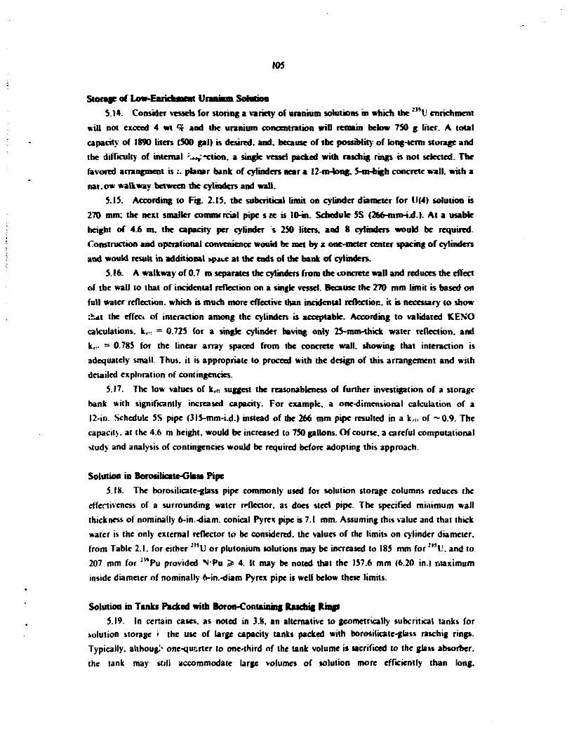
105
Storage of Low-Earichflacnt Uraaiam Sotation 5.14. Consider vessels for storing a variety of uranium solutions in which the * , 5U enrichment
will not exceed 4 wt «£ and the uranium concentration will remain below 750 g liter. A total capacity of 1890 liters (500 gal) is desired, and, because of the possiMity of long-term storage and the difficulty of internal ; .^-ction. a single vessel packed with raschig rings is not selected. The favored arrangment is .'- planar bank of cylinders near a 12-m-long. 5-m-high concrete wall, with a nar.ow walkway between the cylinders and wall.
5.15. According to Fig. 2.15. the subcritkal limit on cylinder diameter for 11(4) solution is 270 mm; the next smaller commrrcial pipe s ze is 10-in. Schedule 5S (266-mm-i.d.). At a usable height of 4.6 m, the capacity per cylinder s 250 liters, and 8 cylinders would be required. Construaion and operational convenience woukl be met by a one-meter center spacing of cylinders and would result in additional *p<"* a* the ends of the bank of cylinders.
5.16. A walkway of 0.7 m separates the cylinders from the concrete wall and reduces the effect of the wall to that of incidental reflection on a single vessel. Because the 270 mm limit is based on full water reflection, which is much more effective than incidental reflection, it is necessary to show ;hat the effect of interaction among the cylinders is acceptable. According to validated KENO calculations. k„. = 0.725 for a single cylinder having only 25-mm-ihkk water reflection, and k«. - 0.785 for the linear array spaced from the concrete wall, showing that interaction is adequately small. Thus, it is appropriate to proceed with the design of this arrangement and with detailed exploration of contingencies.
5.17. The low values of kr i ( suggest the reasonableness of further investigation of a storage bank with significantly increased capacity. For example, a one-dimensional calculation of a 12-m Schedule 5S pipe (315-mm-i.d.) instead of the 266 mm pipe resulted in a k„, of ~0.9. The capacity, at the 4.6 m height, would be increased to 750 gallons. Of course, a careful computational study and analysis of contingencies would be required before adopting this approach.
Solution in Borosilicate-Glass Pipe 5.18. The borosilicate-glass pipe commonly used for solution storage columns reduces the
effectiveness of a surrounding water rrflector. as does steel pipe. The specified minimum wall thickness of nominally 6-in.-diam. conical Pyrex pipe is 7.1 mm. Assuming this value and that thick water is the only external reflector to be considered, the values of the limits on cylinder diameter, from Tabic 2.1. for either 2"l) or plutonium solutions may be increased to 185 mm for "Hi. and to 207 mm for :"Pu provided VPu ^ 4. It may be noted that the 157.6 mm (6.20 in.) maximum inside diameter of nominally 6-in.-diam Pyrex pipe is well below these limits.
Solution in Tanks Packed with Boron-Containing Raicbtt Rings 5.19. In certain cases, as noted in 3.8. an alternative to geometrically subcritical tanks for
solution storage i the use of large capacity tanks packed with borosilicate-glass raschig rings. Typically, although one-quarter to one-third of the tank volume is sacrificed to the glass absorber, the tank may still accommodate large volumes of solution more efficiently than long.

106
limited-diameter cylinders or thin slab-like containers. In addition to primary criticality control, as for in-process storage, raschig rings in auxiliary tanks may protect against accidental criticality resulting tram inadvertent diversion of fissile solution to those tanks.
5.20. American National Standi ' Use of Borosilicate-Glass Raschig Rings as a Neutron Absorber in Solutions of Fissile Material,1* NI6.4-I97I, defines appropriate conditions for criticality control. Restrictions exclude the use of aikline solutions, HF, and hot. concentrated H?PO«. Temperature and radiation fields also are limiteu. The Standard defines chemical and physical propeitn^ that are typified by Pyrex type 7740 and Kimbal type KG-33 and limits the ring size to ^38.1-mm-o.d. It specifies packing conditions and gives requirements for inspection and maintenance. Finally, maximum concentrations of fissile materials in vessels of unlimited size are specified for i iree different volume percentages of glass. Typically, as the glass volume fraction ranges from 0.24 to 0.32. concentration limits range from 270 to 400 g liter for "'L'-enriched uranium, from ISO to 200 g. liter for 2 > > U . from 115 to lov g Pu, liter for z "Pu, and from 140 to 220 g Pu liter for plutonium containing more than 5 wt % ""Pu (see 3.6).
5.21. Although it is unlikely that these reasonably generous limits would restrict a practical process, there could be unusual circumstances that would require greater concentrations. Because computational models cannot closely approximate randomly packed raschig rings.72 the preferred guidance for increased limits would be experimental data near the desired conditions or computed data verified by in situ neutron multiplication measurements.12 An example of an experimental system that is subcritical at a plutonium concentration greater than that permitted by the Standard is reported by Uoyd, Bierman, and Clayton.71 The subcritical concentration of plutonium (8.3 wt % M P u ) in nitrate solution was 391 g/ liter when a 610-mm-diam tank was filled to a depth of 991 mm. Raschig rings containing 4.0 wt % boron occupied 18.8% of the voi:ime. and there was an effectively infinite water reflector on the tank walls and base.
5.22. Nurmi M reports the use of borosilicate-glass rings with enrich xl uranium solutions that have free fluoride-ion concentrations greatly exceeding the limit specified n the Standard. Because of this deviation, there is daily visual inspection and semiannual emptying of tanks for detailed examination, a more stringent maintenance schedule than that required by the Standard.
5.23. Another approach to environments that are hostile to borosilicate glass is suggested by experiments at Battelle Pacific Northwest Laboratories71 with plutonium solutions in a tank packed with stainless steel raschig rings containing 1.0 wt % boron. A 457-mm-diam lank, water reflected on sides and bottom, was packed with 12.7-mm-o.d., 12.7-mnvlong steel rings occupying 27.0% of the volume. At a depth of 991 mm. plutonium (8.3 wt % , M P u ) solutions at concentrations of 275 g Pu/liter with 480 g NO»/liter and of 412 g Pu/liter with 602 g NOj, liter were subcritical.
5.24. A further example includes data on plutonium-uranium nitrate mixtures in a 6IO-mm-{24-in.-) diam tank, water reflected on the sides and bottom and packed with glass raschig rings containing 4 wt % boron.7''75 The raschig rings, which were 38.1-mm-o.d. and 43.2 mm in length, displaced 18.8% of the solution volume. At a depth of 904 mm, solution at a concentration of 78.4 g Pu/liter (5.7 wt % 2 4 0 Pu in Pu) and 180 g U liter (0.66 wt % " 5 U in U) containing 377 g NOi/liter was subcritical.

107
Soluble Neutron Absorber 5.25. Data have recently been reported1* on gadolinium-poisoned aqueous plutonium-uranhim
solutions in which the plutonhim content was near 30 wt 9c- The criticality measurements were performed in a 610-mm-diam tank reflected by water on the sides and bottom. The 24*Pu concentration in the plutonkim was 5.77 wt % and the : "U content of die uranium was 0.66 wt %. Gadolinium was homogeneously mixed with the plutomum-ut*nium nitrate solution. The Pu+U concentration ranged between 248 and 255 g liter, and the corresponding total nitrate concentrations ranged between 365 and 384 g/liter. The critical solution height increased from 191 mm to 753 mm with die addition of 1.06 g Gd liter. The concentration of gadolinium in the above solution required to reduce k- 'o unity in vessek of unlimited capacity was calculated to be 1.86 g.; liter. Doubling the Pu+U concentration from 254 to 508 g, liter would require almost tripling the gadolinium concentration (to 4.8 g Gd/ liter) to maintain k« at unity due to the decreased effectiveness of the gadolinium at lower H-to-fissile-material atomic ratios.
Pipe Intersection Design 5.26. An operation requires that a supply of PufNOi)* solution at a concentration of 25 g of
plutonium per liter be transferred from a storage system to a manifold that will distribute solution uniformly to seven process columns. Tl<e columns lie in a plane, axes parallel, and are spaced 0.7 m between centers except the center separation of the sixth and seventh columns is 0.4 m. The bank of columns is supported from a concrete wall with 200 mm separation between the column and wall surfaces. The subcriticaUty of the configuration has been evaluated and the system has an expected maximum k„t of 0.8. The axis of the manifold is perpendicular to and in the plane of the columns and is located 100 mm from a concrete floor and 500 mm from the base of the columns. The arms connecting the manifold and the columns are coaxial with the columns. The axes of the arms arc normal to the manifold except for the third, which forms an angle of 55 s with the manifold axis. The diameter of the manifold and the connecting pipes is to be determined.
5.27. Each of the first five arms intersecting the manifold lies within a section as defined in 2.24, i.e.. the spacing is greater than 0.5 m. The sixth and seventh arms lie in the same section and quadrant. The permitted maximum diameters, by Table 2.8, are 140 mm for the manifold and 104 mm for the connecting pipes. The third, sixth and seventh arms must be reduced as required by 2.26. The diameter of the third arm is reduced by the factor \/sin 55° to maintain the area of intersection corresponding to the 104-mm-diam. The resulting dimension is 104 \/*in 55° = 94 mm. The combined areas of the sixth and seventh pipes must not exceed the area corresponding to the tabulated diameter. The maximum permitted value of these two tec connections is, thus. 104, \fl = 73.5 mm. In general, for equal areas of n arms in the same section and quadrant, the permitted diameters are given by I, \fn of the tabulated diameter.

108
Solution Holdup Design 5.28. A cell in a 2 , , U reprocessing facility has a floor area of 9 m2 and analyses have shown
that the neuton interaction among the process vessels and between the vessels and the floor is negligible. The floor will serve as a catch basin for solutions that may leak from the vessels. An overflow line installed in the floor, draining to a catch tank, will control the thickness of solution. The maximum expected 2"V concentration in UCWN'OO: is 250 g liter. A permitted solution height over the floor is to be determined. The configuration of the solution is conservatively approximated by an effectively infinite uniform slab of solution reflected on one side of by thick concrete and on the other side by no more than the equivalent of 25 mm thickness of water.
< 29. From Fig. 2.8, the specified subcritical thickness of an infinite slab of :"<JCMN0i): reflected by 25-mm-thick water is 70 mm, and when reflected by 300-mm-thick water is 36.5 mm. A thick concrete reflector on both sides of the slab would reduce the solution thickness to
t = 36.5 (0.44K0.25)'o ,"
= 20-mm
by 3.16. The minimum thickness for the solution is. then, the average thickness for the two reflectors:
. - '' + ': _ 70 ^ 20 . . t 2 7 = m m '
The specified height jf the overflow pipe would not exceed 4* —"i.
Transportation of U(30) as Oxide 5.30. A product, U(30)O;, is to be shipped in Specification 6M packaging. Department of
Transportation (DOT) specifications for 6M packaging call for a cylindrical 2R inner container of 13.3 cm (f .25 in.) maximum inside diameter, a minimum height of 15 cm, protected by industrial cane fiberboard having a density of at least 0.24 ^ cm' (15 lb/ft') and an outer shell of steel. For efficiency, a mass of oxide per package of 45 kg [40 kg U(30)] is proposed. The high-fired oxide can be packed at a maximum density of 0.5 theoretical, i.e.. about 5.4 kg/ liter. Preliminary evaluation is desired for a proposal to use 5-in.-Schedule 40 pipe (12.8-cm-i.d.) with Cclotex insulating fiberboard in a 208 liter (55 gal) steel drum.
5.31. The package of 45 kg of U(30)O; would contain about 12 kg 2 H U and therefore would meet the DOT specifications of 13.9 kg of J , 5 U with corresponding minimum Tl assignment of 0.5. The subcriticality of a single package immersed in water and flooded internally must be demonstrated*1 as called for in 10 CFR 71. When flooded internally, 50% of the inner container volume would b<: occupied by water and produce an atomic ratio of H:U <3. Confirmation of single package subcr.ticality as well as the subcriticality of an array of packages is readily accomplished by we of the Storage Guide,5* NI6.5-1975. Table 5.6 of NI6.5 presents specifications for air-spaced spherical masses of U(30)Oi as a function of number of units and of spacing in water reflected

109
arrays. An entry of 44.5 kg U(30) (~50 kg oxide) ir. Table 5.6 for material wkh an H : U O represents a spherical unit that is less than 90% of the reflected critical mass for this material. A single submerged and flooded package is. therefore, subcritical. An entry in the same table for the atomic ratio H:U 0.4. representing the dry compound in normal transport, is 43.7 kg U(30) (~50 kg oxide) for 512 units, each in a SO cm cubic cell. This entry establishes the subcritkality of the array of packages having 45 kg U(30)Ch and would permit assignment of the minimum T. of 0.5.
5.32. The margin of sufecricicaJity of the array of packages is greater than that of the storage array because of the larger package volume, lower uranium content, cylindrical shape of the unit, and presence of the packaging materials." This information provides a reasonable basis for adopting the design and for proceeding to satisfy ether DOT requirements.
A Storage Amy foi U(93) Metal 5.33. It is desired to establish that a 6 x 6 x 3 storage array of 20 kg U(93) meul cylinders
(HD = 1) is subcritical by an acceptable margin and to examine operational contingencies. Each cylinder of metal is stored in a 50-cm-dimensioned cubic birdcage having a centered aluminum container which has sufficient capacity to accommodate six units although only one is permitted. The array is to be close-packed and located in a large room with overhead water sprinklers for fire protection.
5.34. Subcriticality of the array was demonstrated by calculations performed with ? validated version of the KENO Monte Carlo code and using the Hanscn-Roach 16-energy-group neutron cross sections. Results were compared to similar arrays described in Ref. 78. The array with full reflection (60-cm-thick concrete floor and ceiling and 15-cm-thick water walls) had a calculated krii ± " of 0.90 ±0.01. Double loading a central unit increased the k,« of the array approximately 2%. Interspersed water moderation at optimum density increased k,(( approximately 4%.
5.35. Four contingencies were considered and countermeasures proposed: a. Overloading of a container: Two independent mass checks are required on
each piece. All containers are closed except the one being loaded in order to prevent a dropped metal cylinder from falling onto another.
b. Extending the array: Boundaries are marked on the floor, and a posted sign prescribes a stacking height of only three birdcages.
c. Loss of spacing: Only 20-in. or larger birdcages s»re available. Heavy equipment is kept out of the array area. Combustibles that might cause a fire and melt the aluminum birdcages are excluded from the area, and water sprinklers are installed overhead.
d. Operator not understanding what is approved: The criticality safety analysis and the operating procedures are written and reviewed. The operators attend training sessions. Mass limits per container and array stacking height are pc >ted. Array boundaries are marked on the floor.

no
Fuel Element Fabrication 5.36. A fuel element fabrication plant proposes to produce aluminum-clad uranium oxide fuel
elements for reactors. The program requires the fabrication of the fuel plates and their asseir.oly into fuel elements. The primary method of control is to be by batch size since this method integrates well with the requirements of quality assurance procedures. The plates are to be fabricated from a mixture of aluminum powder and UjO, (93 wt % 2'5U) powder, which is formed into compacts, placed in aluminum metal frames, clad with aluminum cover plates and hot-roll bonded. The plates are assembled and welded into fuel elements and the elements ar? machined. They are then cleaned, inspected, and stored until shipped to the purchaser. A flow diagram of the operation is given >n Fig. 5.1. It 15 significant to note in the following that control of internal moderation of fissile materials during fabrication is important and greatly simplifies the criticality assessment of the program.
5.37. The UjO» is received in metal cans about 15 cm in diameter and 22 cm tall (volume of ~3.92 liters) with press-fitting covers. The mass per can does not exceed 7.0 kg ot uranium, equally divided into two polyethylene bags. A can of oxide is to be stored ( (7) of Fig. 5.1) in the shipping containers, which are birdcages ~50 cm on a ..ide (volume of ~!3I liters) with a centered 6-in. Schedule 40 pipe. The oxide is nominally dry, i.e., contains less than 1.5 wt % moisture (H:U ~0.4), and Table 5.2 of NI6.5 allows 13.9 kg of uranium lor a cubic cell dimension of 50 cm in a water-reflected array of 1000 units. This mass limit is reduced to 8.3 kg of uranium for a concrete-reflected array by 5.4 of N16.5 Alternately, the oxide container is in mass category L by Table 4.1 of Chapter IV, and, by Table 4.2 and Eq. 4.2, the birdcage would be labeled with a criticality indicator, CI, of 0.08. There are no additional requirements, assuming that the maximum number of birdcages is 20. Only two containers will be open during operations in the storage area. Double batching, 14.0 kg U is a subcritical quantity by mass category W and, therefore, not a significant contingency.
5.38. The contents of two birdcages are transferred to the blending area ( Q ) of Fig. 5.1) and 7.0 kg U emptied into each of two containers of ~5.6 liter capacity. The con1 :d in a Vee-blender and blended for 30 minutes. The 14.0 kg U in this operation, as in the storage area, falls in the mass category W of Table 4.1 which, being a single letter designation, is ubcritical when reflected by water. After blending, these containers are rlaced in a storage vault,(T) . The vault has a set of shelves attached to a wall so that the stored containers form a planar array with center separation of 33.5 cm in the plane. The shelves arc constructed in a maimer to prevent double loading a storage cell. This mass category L unit, now in a 37.6 liter cell, is assigned a CI of 0.81 by Table 4.2.
5.39. When required, 0.6 kg U is weighed into a batch can and transferred to the compact weighing station, (7) . An amount of UjO* satisfying specifications for a single plate (usually less than 25 g of U) is weighed into each of 24 coded, glass, screw-capped, 5.7-cm-diam jars 6.3 cm tall. The contents of the 24 jars constitute a quality control batch and will be processed as a unit. A measured quantity of aluminum powder is added to the jars. The 24 jars are sealed and transferred to an oblique blender, (?), where they are blended for two hours. The blended powder is then ready
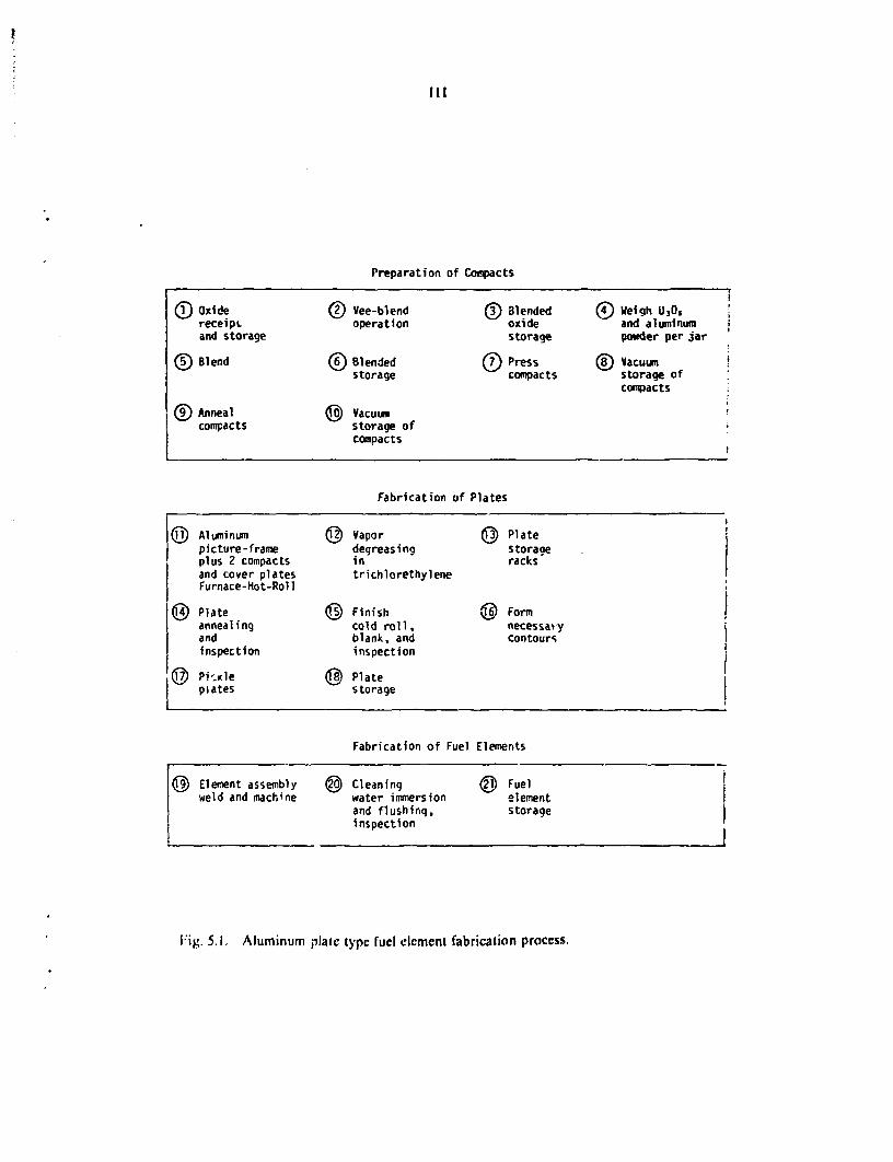
lit
Preparation of Compacts
0 Oxide receipt and storage
@ Blend
(§) Anneal compacts
© Vee-blend operation
© Blended storage
JO) Vacuum storage of compacts
( D Blended oxide storage
0 Press compacts
I 0 Weigh U,0, '•
and aluminum f powder per jar
0 Vacuum storage of compacts
i
Fabrication of Plates
(fj) Aluminum picture-frame plus 2 compacts and cover plates Furnace-Hot-Roll
© Vapor degreasing in trichlorethylene
@ Plate storage racks'
© Plate © Finish © Form annealing and inspection
cold r o l l , blank, and inspection
necessary contours
© Pi'.Kle piates
© Plate storage
Fabrication of Fuel Elements
JJ) Element assembly weld and machine
@ Cleaning water immersion and flushing, Inspection
(21) Fuel element storage
f ig. 5.1. Aluminum plate type fuel element fabrication process.
112
for pressing into fuel compacts. The jars are placed in a tray accommodating a 4 x 6 arrangement and the trays are transferred to a work station storage array.\t\, in the compact pressing area. This storage array consists of six open metal shelves 38 cm deep by i.O m wide separated 20 cm vertically. Four trays are allowed on a shelf, which defines an associated cell volume of ~19 liters for each tray. The 0.6 kg U per tray is mass category A from Table 4.1, and Table 4.2 gives CI = 0.08 for each tray location.
5.40. The powder is compacted, Qy, on a hydraulic press. The blended powders are poured from a jar into a die cavity and pressed into a compact approximately 5.5 x 6.7 x 0.7 cm. The 24 compacts are inspected, given identification numbers, and placed on edge in a covered stainless steel tray 12.7 x 20 x 8.3 cm. Quality control requires storage of the c -mpacts in a vacuum before and after annealing. The vacuum storage chamber,(?) and HO), is ~0.5 x 0.5 x 0.6 m and has two shelves separated by ~0.3 m. Each shelf will accommodate eight trays of compacts. The capacity of the vacuum chamber is less than 8 kg U, which is mass category N by Table 4.1. Since the volume of the chamber is ~ 150 liters, it would be labeled with a CI of 0.11 by both Table 4.2 and Eq. 4.2.
5.41. The presses compacts are vacuum annealed in a cylindrical furnace 0.5 m in diameter by 0.7 m deep,\9) . The outer surface of the furnace is water-cooled. Leakage or rupture of the water lines on the outer shell of the furnace cannot result in water entering the interior of the furnace. There are three shelves in the furnace, each of which will accommodate a single metal tray holding 48 compacts. The maximum loading is 3.6 kg U (mass category E by Table 4.1) and is an acceptable subcritical operation. After annealing, the compacts are returned to the vacuum storage chamber.
5.42. A batch of 24 compacts is visually and dimensionally inspected at a work tabic. Acceptable compacts are assembled into rolling packages consisting of two fuel compacts, one aluminum picture frame and two aluminum cover plates, Q7) . Packages have nominal dimensions of 21 x 15.5 x 1.5 cm. The package is hot-rolled to a thickness of ~2.5 mm. The two fuel sections arc separated by shearing and finish-rolled to ~1.5 mm. The plates are cooled on a metal table and transferred to a rack, (n) , for storage and transport to subsequent operations. The rack is 38 x 20 x 90 cm and holds the 24 plates with ~2.5 cm space between plates. The plates are transferred to a vapor degreasing operation, (J2) • The degreasing medium is trichlorethylene, which is not as effective a moderator as water. Table 2.1 gives a subcritical mass limit for J 3 , U of 0.76 kg or, more conservatively, Fig. 2.1 gives 0.64 kg " $U, either of which is greater than the uranium content of the 24 plates. In addition, the lower 2 J , U enrichment of the uranium, the presence of 23*U in the pi ites. and the latticing of fissile materials in water at this 2 3 5U enrichment increase the margin of sur criticality. This limit, one rack of 24 plates, is also applicable for the later pickling o( plates, (\j) . The rack is designed to hold only 24 plates, therefore double batching is not a contingency.
5.43. There fellow the operations of flatten-annealing, ( u ) , inspections, location of fuel region, blanking to finish dimensions, (\5), and forming plates to necessary contours, (jo) . Since each operation, except the fiatten-annealing, involves no more than a batch of 24 r'alrs, no additional procedures for criticality control are necessary. The flatten-annealing operation is
113
economically conducted with multiple batches, for example. 18 batches corresponding to 10.8 kg U. The plates are sucked between aluminum platens and single or multiple sucks placed in a furnace. ?-'ote that protection from sprinklers would be necessary if the plates were other than close packed in the suck. The subcritical limit of 14.4 kg U, category W of Table 4.1, may be used for this operation. Note th?t the dilution of fissile material by the aluminum, a geometry less reactive than a sphere, and the absence of moderation provide a large margin of subcritkality for the operation. A batch of 24 plates is boxed in a configuration that provides physical protection for the plates and is stored until needed for fuel element assembly.
5.44. Storage in an aluminum box, 1S.2 x 3S.6 x 61.0 cm. having u poh/vinylchloride* (PVC) insert uniformly spaces the plates in a 3 x 8 matrix. The PVC between fuel plates, about 800 g, produces an H:U ratio of
™ = 3 £§ xf = , s
Table 4.1 does not provide a mass category for materials at an H:U - 15. In order to assign a mass category to the box, the H:U may be consenatively regarded as 20 and the equivalent arrays of NI6.5 used to identify a unit at an H:U = 0.4 that would be equivalent to the box of plates with the PVC moderator. A cell dimension for the box tne cube root of its volume, is 32 cm. Table 5.2 of NI6.5 allows 1000 units, each containing I Kg V as U(93)0 : at an H:U^20,for cubic cells with a 30.5 cm edge. Application of this set of parameters to the larger dimension of the box is conservative. Also from Table 5.2. an array of the same dimensions and number of units but of material at an H:U^0.4, 5.8 kg U per unit is permitted. A concrete-reflected array requires a mass reduction to 60% or 3.5 kg U ,5.4 of NI6.5). The 3.5 kg U at an H:U = 0.4, equivalent to the box with 24 plates in the PVC matrix, is a mass category D by Table 4.1.
5.45. These boxes are stored, (Is), in a plane for accessibility such that the vertical and horizontal center separation of boxes are 30.5 and 50.8 cm, respectively. The cell volume associated with each 61 cm long box is 98.4 liters. The Ci assigned to each cell is, therefore, 0.01 from Table 4.2. These storage arrays may be conveniently distributed throughout the fabrication area without concern tor location. Requirements are only that the sum of the CI for individual areas should not exceed 100 and that interna! moderation of fissile materials from, for example, a plant sprinkler system, be prevented.
5.46. There are sufficient critical experiment data with aluminum-clad fuel plates to define safe operations with fabricated elements.79'*0 The Oak Ridge Research Reactor box-type elements contain 180 g of U(93) in 19 plates, f he SPERT-D element is similar, having 330 g of U(93) in 22 plates. A third example is the Oak Ridge High Flux Isotope Reactor (HFIR) element composed of approximately 10.1 kg of uranium contained in two coaxial annuli. The outer annulus has an inside diameter of 28.5 cm, an outside diameter of 43.5 cm and consists of 369 fuel plates with about 7.3 kg of U. The inner annulus has inner and outer diameters of 12.9 cm and 26.9 cm, respectively, and 171 plates containing 2.8 kg of U. The inner annulus also contains some boron mixed with the fissile material. Some relevant measurements with these elements are:
•Polyvinylchloride is CH^HCI.

114
a. Fifteen ORR dements, water-moderated and water-reflected at optimum spacing are critical. This corresponds to 2.7 kg of U.
b. Twelve submerged SPERT-D dements at optimum spacing are required for criticality. This corresponds to about 3.9 kg of U.
c. An assembled HFIR core (combined inner and oufer annuli) is subcritkal submerged. The typical reactivity range is from I.S to 3.5 dollars subcritical.
These data are sufficient to establish quantities for the subcriticality of the typical operations of assembly, machining, ( m , and cleaning, Qffl of Fig. S.l. For example, submersion and flushing of the separated inner and outer components of a HFIR clement provides an additional large margin of safety.
S.47. Additional experimental data with the HFIR elements show that:
a. Seven assembled cores submerged in water are neutronically decoupled when their surfaces are separated by 200 mm.
b. Eight inner and eight outer annuli in any arrangement in air show no appreciable neutron multiplication.
% As an illustration, transfer and storage of HFIR elements would be assessed as follows. For ease in transport, for physical protection, and for nuclear criticality safety in case of flooding, a minimum surface separation of 20 cm between HFIR components should be maintained. The annuli should be covered when not at a work station. They may be stored and transported, (2l), in the plant on carts that are ~60 x 60 cm in cross section. The height of a component, about I m, and the cart dimensions define an associated cell volume of ~360 liters. The 7.3 kg of U is a mass category I. and, by Table 4.2. the carts would be labeled with a CI of 0.02, suitable for either an inner or an outer component. In this use of the CI system, there is again no administrative requirement on the location of carts in the plant areas.

5 I f I
I I
fe
APPENDIX
CRITICALITY OF SPECIAL ACTINIDb ELEMENTS

117
APPENDIX
CRITICALITY OF SPECIAL ACT1N1DE ELEMENTS A.I. Although the principal interest in criticality to date has centered on uranium and
plutonium, a number of isotopes of other elements within the actinide group also are capable of supporting a chain reaction. It has been speculated that potential requirements for certain of the synthetic actinide elements could lead to their production in large, possibly ton, quantities.*1'12
Calculations or measurements of criticality show extreme variations in their critical masses, ranging from gram to kilogram quantities, under like conditions. These variations depend on the nuclear makeup of the isotope in question, its evenness or oddness, Z2/ A, activation energy for fission, and the energy available on absorption of a neutron.*1
A.2. To be forewarned about potential criticality problems with these special actinide elements, it is necessary to resort to calculations without the benefit of validating raperimental data. In spite of this handicap, however, significant conclusions can be drawn. The key to potential criticality is whether the nuclide contains an even or odd number of neutrons, N. Those with odd numbers of neutrons can be expected to have critical masses in aqueous solutions that are less than one kilogram, and, in certain cases, remarkably small values of critical mass have been reported for some of these highly fissile odd-N nuclides; to illustrate, the critical mass of "}Cf as a sphere of aqueous solution at optimum moderation was calculated*4 to be only 10 g.
Odd-N Nuclides A.3. The nuclides 2«Pu, 2",Am, ^Cm, 'gCm. %Cm, 2£Cf, and 2JiCf all contain odd numbers
of neutrons, each is highly fissile, and moderation leads to reduced critical masses. Minimum critical masses, as computed by Clark,*4 are included in Table 5.1 for several of these nuclides. It should be borne in mind that, although the critical masses are small, the quantities available are likely to be extremely limited. For example, there is nov now 10 g of "JCf available, nor is there likely to be for some time to come.
Even-N Nuclides A.4. Nuclides such as 2JiPa, 2gNp, 2gPu, 'fiPu, uJ>\m, I 4 4Cm, and JgCf, contain even
numbers of neutrons, and, although criticality may be possible, the effect of moderation is to prevent rather than to enhance criticality. Computed critical masses for a number of the even-N nuclides are also included in Table A.I.
A.5. The actinides containing even numbers of neutrons characteristically exhibit rather sharp thresholds in their fission cross sections, with little o; no probability of subthreshold fission. As a consequence, the value of k- will be sharply reduced if even a small quantity of hydrogen is mixed with the element." The effect of energy degradation also becomes evident in the reflector savings of such a system. A good moderating material, such as water, returns to the core neutrons of reduced

BLANK PAGE /
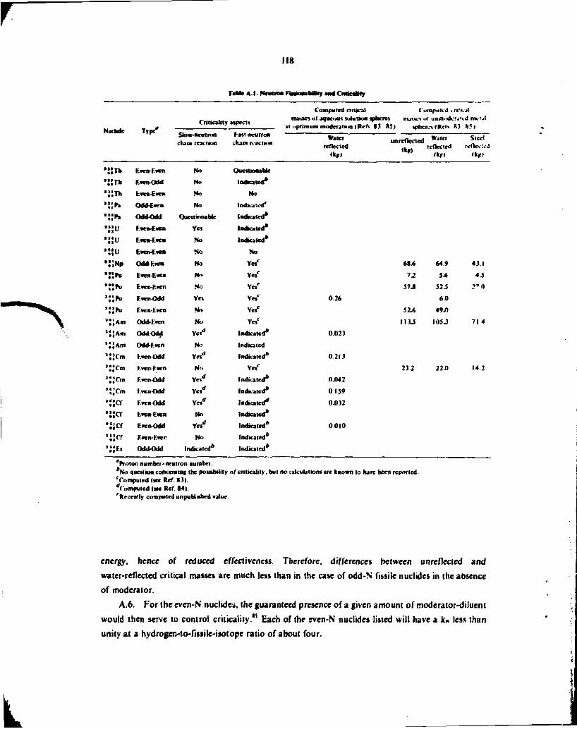
118
TaMe A.I . Neutron Fia • b * y and Criticality
Type* Criticality atpccH
Computed cntkal maoe. of aqueom totution tphem
at optimum moderation tRefv 83 85)
* • » un reflected
Computed i mawn of unmtrfk
iphcri-t (Rett
nTR.al rjTcii mvTjl 83 85l
Nudadc Type* Sowncatn>n cham i ( K i « »
E»f -neutron cham reaction
Computed cntkal maoe. of aqueom totution tphem
at optimum moderation tRefv 83 85)
* • » un reflected
Computed i mawn of unmtrfk
iphcri-t (Rett Type* Sowncatn>n cham i ( K i « »
E»f -neutron cham reaction
Computed cntkal maoe. of aqueom totution tphem
at optimum moderation tRefv 83 85)
* • » un reflected
reflected Water reflected
Sled reflcvicJ
lk<>
• » T b Even-Even No Qucitnaabk
*::Tfc Even-Odd No Indicated*
"JjTh Even-Even No No
•;ih Odd-Even No Indicated' ***»» • i * » Odd-Odd Questionable Indicated*
Even-Even Vei Indicated*
Even-Even No Indicated* Even-Even No No
T.Np Odd-Even No Ye. r 6SA 64.9 43.1
• » P » Even-Even No Ye, c 12 5.6 4 J
•J'Pu Even-Even No Ye.' 57J 523 ?->0
' : > Even-Odd Ves Ye.' 0.26 6 0
"Hh Even-Even No Ye,' 52.6 49 A
*:iAm Odd-Even No Ye.' I I 3 J I05J 71 4
".{Am Odd-Odd Ye." Indicated* Oi)23
" { A m Odd-Even f*> Indicated
",'Cm Even-Odd Ye." Indicated* 0.213
'::cm Even-Even No Ye,' 23.2 22.0 14 2
»,«Cm Even-Odd Y « " Indicated 0.042
"JCm Even-Odd Ye." Indicated 0 159
'JJCf Even-Odd Ye." Indicated" 0.032
>i;a Even-Even No Indicated*
»;;cf Even-Odd Ye." Indicated* 0 0 1 0
'JJCf Even-Ever No Indicated*
» ; E . Odd-Odd Indicated* Indicated*
'proton number-neutron number. No queMun concerning the potability of criticality, but no calculation, are known to have been reported.
'Computed (KC Ref. 83). "Computed (tee Ref. 84). 'Recently computed unpubinhed value.
energy, hence of reduced effectiveness. Therefore, differences between unreflected and water-refleaed critical masses are much less than in the case of odd-N fissile nuclides in the absence of moderator.
A.6. For the evcn-N nuclide*, the guaranteed presence of a given amount of moderator-diluent would then serve to control criticality." Each of the sven-N nuclides listed will have a k« less than unity at a hydrogen-to-fissile-isotope ratio of about four.

119
A Precaution Concerning Mixtures of 'SCm and 2SCm A.7. With possible future production of : 4 4Cm in large (perhaps ton) quantities, consideration
must be given to the effect on criticality of the presence of even small concentrations of the odd-N fissile isotopes, particularly 2 4 ,Cm. Calculations by Clark** indicate that the minimum critical mass of a homogeneous mixture of M ,Cm in water is only 42 g (sec Table A.I), which occurs at a '"Cm concentration of about IS g liter. Table A.2 gives the results of other calculations by Clark of water-reflected spherical critical masses for homogeneous mixtures of I4*Cm and M 5 Cm with optimum water moderation. These values show the need for considering the effect that small quantities of the highiy fissile **'Cm isotope can have on the criticality of the mixture. For example, if only 2 wt °k of M ! Cm were present in the 14*Cm-M5Cm mixture, the water-reflected critical mass of this mixture at optimum moderation would be only about 7 kg of curium. It is evident that small amounts of the highly fissile "'Cm isotope become the determining factor affecting criticality. Similarly, the effect that other fissile isotopes of curium may have on the criticality of w C m must be considered.
raWe A J . Calculated Critical HMa o f ' " C m - , 4 4 C m Mixture*
Thick water reflector, optimum water moderation,
spherical geometry
"*Cm/"'Cm Critical man Atom ratio Total Cm (g) "*Cm(g)
0 42 42 20 1596 76 30 2914 94 40 4674 114 50 6987 137
100 <42,400 <420
Safety Limits for Special Aetinide Elements A.8. In tho'e cases where calculated values of critical mass are not available for criticality
control guidance, Table A.I gives an indication of whether the given nuclide would be critical and under what condition of moderation. In the absence of experimental data, there is no means by which the calculated numbers can be validated. Because of their limited availability, it is most unlikely that any of these nuclides will be encountered in quantities that approach the computed critical values. As quantities increase, however, experimental data should provide bases for validation.

121
ACKNOWLEDGMENTS
The second revision of the Nuclear Safety Guide was supported by a contract of the Nuclear Regulatory Commission issued to the Oak Ridge National Laboratory. R. D. Schamberger. the NRC contracting officer. R. I.. Stevenson, and N. D. Ket/lach provided thier patient assistance and guidance during reviews of the various drafts. The successive drafts of the Guide were also reviewed by members of the American Nuclear Society Standards Subcommittee 8 on Fissionable Materials Outside Reactors. The subcommittee is constituted as follows:
F. M. Alcorn Babcock Wilcox Company
H. K. Clark Savannah River Laboratory
E. D. Clayton Battclle-Pacific Northwest Laboratories
D. M. Dawson General Electric Company
E. B. Johnson, Secretary Oak Ridge National Laboratory
Norman Ket/lach U. S. Nuclear Regulatory Commission
J. D. McLendon. Chairman Union Carbide Corporation. Nuclear Div. Oak Ridge Y-12 Plant
W. G Morrison Allied Chemical Company
D. R. Smith Los Alamos Scientific Laboratory
J. T. Thomas Oak Ridge National Laboratory
G. E. Whitesides Oak Ridge National Laboratory
F. E. Wolt/ Goodyear Atomic Corporation
In addition, the contributions of many individuals over the period of several years is gratefully noted. K. R. Schultz. of the Atomic Energy Control Board of Canada, made extensive and detailed suggestions of an early draft which were timely and helpful. Confirmed calculations produced many of the results appearing in the Guide. A significant con.iibution and effort in performing the calculational surveys was provided by the Computer Science. Division at the Oak Ridge National Laboratory. Finally. I would be remiss were I not to recognize the untiring and cheerful effort of Mrs. Brenda Neeley. who did a majority of the typing and retyping «r.d who directed the production of the finished manuscript.
J. T. Thomas
(1977)

123
REFERENCES
i. J. A. McBridc and R. L. Stevenson. "Nuclear Safety in the Materials Licensing Program." Proc. ANS Topical Meeting on Nuclear Criticality Safety. Dec. 13-15. 1966, S C / D C - 6 7 - 1 3 0 5 . Sandia Corporation (1967).
2. H. C. Paxton. J. T. Thomas. A. D. Callihan. and E. B. Johnson (eds.). Critical Dimensions of Systems Containing if*. Pu1". and U2", TID-7028. U.S. Atomic Energy Commission (1964).
3. H. C. Paxton, Criticality Control in Operations with Fissile Material. LA-3366 (Rev.). Los Alamos Scientific Laboratory (1972).
4. American National Standard Validation of CaJculational Methods for Nuclear Criticality Safety. NI6.9-I975; published by American Nuclear Society. 5SS N. Kensington Avenue. La Grange Park, IL.
5. S. Glasstone and M. C. Edlund, The Elements of Nuclear Reactor Theory, D. Van Nostrand Co.. Inc.. Princeton. NJ (1952).
6. A. M. Weinburg and E. P. Wigner. The Physical Theory of Neutron Cham Reactors. The University of Chicago Press, Chicago (1958).
7. H. S. lsbin. Introductory Nuclear Reactor Theory. Reinhold Publishing Corp.. New York (1963).
8. E. D. Clayton. Anomalies of Criticality. BNWL-SA-4868 (Rev. 3). Battclle Pacific Northwest Laboratories (1976).
9. American National Standard for Nuclear Criticality Safety in Operations with Fissionable Material* Outside Reactors, N16.1-1975; published by American Nuclear Society. 555 N. Kensington Avenue. La Grange Park, IL.
10. American National Standard Criteria for Nuclear Criticality Safety Controls m Operations where Shielding Protects Personnel, N 16.8-1975; published by American Nuclear Society. 555 N. Kensington Avenue. La Grange Park. IL.
11. American National Standard Safety Guide for the Performance of Critical Experiments. N4Q5-I975; published by American Nuclear Society. 555 V Kensington Avenue. La Grange Pa f
12. Amer. National Standard for Safety in Conducting Subcritical Neutron-Multiplication Measurements IN SITU, NI6.3-I975; published by American Nuclear Society. 555 N. Kensington Avenue, La Grange Park. IL.
13. American National Standard Use of Borosilkate-Glass Raschig Rings as a Neutron Absorber in Solutions of Fissile Material. N 16.4-197!; published by American Nuclear Society, 555 V Kensington Avenue, La Grange Park, IL.
14. R. G, Taylor. Monitoring for Uranium Accummulatiom in Diffusion Plant Equipment. K/L-6316. Oak Ridge Gaseous Diffusion Plant (1973).
15. J. L. Forstner. "Nuclear Safety Control in the Chemical Processing Facilities of the Savannah River Plant," Proc. of IAEA Stockholm Symposium on Criticality Control of Fissile Materials, p. 621. International Atomic Energy Agency, Vienna (1966).
16. W. R. Scratton. A Review of Criticality Accidents. LA-3611. Los Alamos Scientific Laboratory (1967).

124
17. T. L. Shipman. "Actual Radiation Death Resulting from an Accidental Nuclear Critical Excursion". J. Occ. Med.. J, 147-150 (1961).
18. E. R. Martin. D. F. Jones, and L. G. Speir. Passive Segmented Gamma Scan Operation Manual. LA-S652-M. Los Alamos Scientific Laboratory (1974).
19. R. B. Walton. E. I. Whined, and R. A. Forster, "Gamma-Ray Assay of Low-Enriched Uranium Was'e." Sucl. Tech.. 24, 81 (1974).
2C. C. J. fmbarger and L. R. Cowder. "Portable Radioactivity Monitor for Liquid Effluents, Surface Contaminations, and Bulk Solid Wastes." Nucl. Instrum. Methods, 121,491 (1974).
21. R. Berg. G. Birkhoff. L Bondar, G. Busca. J. Ley. and R- Swennen, On the Determination of the Pu-240 in Solid Waste Containers by Spontaneous Fission Neutron Measurements. Application to Reprocessing Plant Waste. EUR 5158e (1974).
22. T. D. Reilly, E. R. Martin. J. L. Parker, L. G. Speir and R. D. Walton. "A Continuous In-Linc Monitor for UF» Enrichment," Nucl. Tech.. 23. 318 (1974).
23. J. T. Mihalczo, Randomly Pulsed Neutron Measurements for Safeguards Interrogation, Y/DR-79, Oak Ridge Y-12 Plant (1972).
24. J- E. Foley and L. R. Cowder, Assay of the Uranium Conttnt of Rover Scrap with the Random Source Interrogation System, LA-5692-MS. Los Alamos Scientific Laboratory (1974).
25. American National Standard Criticality Accident Alarm System, N 16.2-1969; published by American Nuclear Society, 555 X. Kensington Avenue, La Grange Park, IL.
26. R. L. Scale, "Consequences of Criticality Accidents." Proc. UNM Short Course on Nuclear Criticality Safety. May 7-11. 1973. p. 16. TID-26286, U. S. Atomic Energy Commission (1974).
27. Dixon (>;lihan and Joseph T. Thomas. "Accidental Radiation Excursion at the Oak Ridge Y-12 Plant - I," Health Phys.. I. 363 (1959), J. D. McLendon, "Accidental Radiation Excursion at the Oak Ridge Y-12 Plant - II," Health Phys.. 2, 21 (1959); G. S. Hurst. R. H. Richie, and L. C. Emerson, "Accidental Radiation Excursion at the Oak Ridge Y-12 Plant - III," Health Phys.. 2. 121 (1959).
28. W. C. Roesch et a/., "Dosimetry Investigation of the Recuplex Criticality Accident," Health Phys.. 9. 757 (1963).
29. T. G. Hughes. "Criticality Incident at Windscale," Nucl. Eng. Int.. 17. No. 189. p. 95. (1972).
30. American National Standard Immediate Evacuation Signal for Use in Industrial Installations Where Radiation Exposure May Occur, N2.3-I967; published by American National Standards Institute, 1430 Broadway. New York.
31. P. Lecorchc and R. L. Scale. A Review of the Experiments Performed to Determine the Radiological Consequences of a Criticality Accident, Y/CDC-I2. Oak Ridge Y-12 Plant (1973).
32. Operational Accidents and Radiation Exposure Experience Within the United States Atomic Energy Commission 1943-1970, WASH-1192 U. S. Atomic Energy Commission (1971).
33. Operational Accidents and Radiation Exposure Experience Within the United States Atomic Energy Commission, WASH-1972, U. S. Atomic Energy Commission (1975).

125
34. J. W. Webster. Calculated Neutron Multiplication Factors of Uniform Aqueous Solutions of aiUandmU. ORNL/CDC-2, Union Carbide Corp.. Oak Ridge National Laboratory (1967).
35. C. R. Richey, "Theoretical Analysis of Homogeneous Plutonium Critical Experiments." Nucl. Sci. Eng., 31, 32 (1968).
36. C. R. Richey, "Reexamination of the Value of the Minimum Critical Concentration of 2 3 'Pu in Water," Nucl. Sci. Eng., 55, 244 (1974).
37. H. K. Clark, "Effect of Distribution of Fissile Material on Critical Mass," Nucl. Sci. Eng.. 24, 133 (1966).
38. W. H. Roach and D. R. Smith, Estimates of Maximum Subcritical Dimensions of Single Fissile Metal Units, ORNLACDC-3, Oak Ridge National Laboratory (1967).
39. D. R. Smith and W. U. Geer, "Critical Mass of a Water-Reflected Plutonium Sphere," Nucl. Tech.. 7,405(1969).
40. W. R. Stratton, Criticality Data and Factors Affecting Criticality of Single Homogeneous Units, LA-3612, Los Alamos Scientific Laboratory (1964).
41. D. R. Smith, Los Alamos Scientific Laboratory, (to be published).
42. C. E. Newlon, The Effect of Uranium Density on the Safe 1}iU Enrichment Criterion, K-i550, Oak Ridge Gaseous Diffusion Plant, (1962).
43. E. D. Clayton e: ai, "Basis for Subcritical Limits in Prooosed Criticality Safety Standard for Mixed Oxides," Nuci Tech.. 35, 97 (1977).
44. Savannah River laboratory Quarterly Report, Light Water Reactor Fuel Recycle. July-September. 1976, DPST-LWR-76-1-3, p. 56 (1976).
45. H. K. Clark, Critical and Safe Masses and Dimensions of Lattices of U and UOz Rods in Water, DP-I0I4, Savannah River Laboratory (1966). A shorter version appears in Proc. of the IAEA Symposium on Criticality Control of Fissile Materials, Nov. 1-5, 1965, international Atomic Energy Agency, Vienna (1966).
46. R. C. Lloyd, "Buckling Measurements of Fuel Elements in a Random Array, Water Moderated," Nuclear Physics Quarterly Report, October, November, December, 1957. p. 35, HW-5459I, Hanford Engineering Development Laboratory (1958).
47. R. C. Lloyd. "Buckling Measurements for Fuel Elements in a Random Array." Nuclear Physics Research Quarterly Report, January-March, 1958, p. 12, HW-55&79. Hanford Engineering Development Laboratory (1958).
48. R. C. Lloyd and E. D. Clayton, "Criticality Safety Dan Applicable to Processing Liquid-Metal Fast Breeder Reactor Fuel," Nucl. Sci. Eng., 59, 21 (1976).
49. J. T. Thomas, Calculated Criticality of Water Moderated Oxides of Uranium-233. Thorium-232. and Carbon Mixtures, Y/DR-107, Oak Ridge Y-12 Plant (1973).
50. J. T. Thomas. ORNL CSD TM-36, Oak ^idge National Laboratory, (to be published).
51. R. C Lloyd. C. R. Richey. E. D. Clayton, and D. R. Skeen, "Criticality Studies with Plutonium Solutions," Nucl. Sci. Eng., 25, 165 (1966).
52. Proposeu American National Standard Nuclear Criticality Safety Guide for Pipe Intersections Containing Aqueous Solutions of Enriched Uranyl Nitrate, NI6.7. available from American Nuclear Society, 555 N. Kensington Avenue, La Grange Park, IL.

126
53. R. C. Lloyd, E. D. Clayton, and L. E. Hansen, "Criticality of Plutonium Nitrate Solutions Containing Soluble Gadolinium," Nuel. Sci. Eng.. 48, 300 (1972).
54. R. C. Lloyd and E. D. Clayton, "Effect of Boron and Gadolinium on the Criticality of Plutonium-Uranium Systems," Trans. Am. Nucl. Soc, 23, 234 (1976).
55. E. D. Clayton and C. L. Brown, "Criticality and Nuclear Safety of Slightly Enriched Uranium," Chem. Eng. Prog. Symp. Ser., Vol. 61. No. 60 (1955).
56. *.'. I. Neeley, J. A. Berberet, and R. H. Masterson, * . of Three Weight Percent 23iU Enriched U(h and UCh (NOj)i Hydrogeneous Systems, HW-66882, Hanford Engineering Development Laboratory (1961).
57. R. Gwin and D. W. Magnuson, "The Measurements of Eta and other Nuclear Properties of 2"U and 2 3 5 U in Critic-! Aqueous Solutions," Nucl. Sri. Eng., 12, 364 (1962).
58. American National Standard Guide for Nuclear Criticality Safety in the Storage of Fissile Materials, NI6.5-1975; published by American Nuclear Society, 555 N. Kensington Avenue, La Grange Park, IL.
59. J. 7. Thomas, "Experimental Measurements with Arrays of U(97.7)F6 Neutron-Coupled Through Concrete," Trans. Am. Nucl. Soc, 19, 199 (1974).
60. J. T. Thomas, The Criticality of Cubic Arrays of Fissile Materials, Y/CDC-10, Oak Ridge Y-12 Plant (1971).
61. J. T. Thomas, "Generic Array Criticality," Nuclear Criticality Safety, p. 66, TID-26286, U. S. Atomic Energy Commission (1974).
62. J. T. Thomas, A Criticality Indicator for Storage of Fissile Materials, UCCND/ CSD/ INF-48, Oak Ridge National Laboratory, (1975).
63. Title 10, Chapter 1, Code of Federal Regulations-Enet<"\ Part 71.
64. B. L. Koponen, "Reactivity Enhancement in Transportation and Storage Due to Fissile Material Density Reductions," Nucl. Tech.. 34, 242 (1977).
65. J. T. Thomas, "Remarks on Surface Density and Density Analog Representation of Array Criticality," Trans. Am. Nucl. Soc. 22, 299 (1975).
66. J. T. Thomas, "Surface Density and Density Analogue Models for Criticality in Arrays of Fisiile Materials," Nucl. Sci. Eng.. 62, 424 (1977).
67. H. F. Henry, J. R. Knight and C. E. Newlon, General Application of a Theory of Neutron Interaction, K-I309, Oak Ridge Gaseous Diffusion Plant (1956).
68. J. S. Tang, Investigation of the Solid Angle Method Applied to Reflected Cubic Arrays, ORNL/CSD/TM-13, Oak Ridge National Laboratory (1976).
69. H. K. Clark, "A Simple Practical Method for Calculating Interaction," Proc. of the IAEA Symposium on Criticality Control of Fissile Materials, November 1-5, 1965, International Atomic Energy Agency, Vienna (1966).
70. H. K. Clark, "Interaction of Fissionable Units," Nucl. Sci. Eng.. 15, 20 (1963).
71 H. K. Clark, "Application of a Simple, Practical Method for Computing Interaction to A. rays Found Experimentally to be Critical," Nucl. Sci. Eng., 20. 307 (1964).
72. J. P. Nichols, C. L. Schuske and D. W. Magnuson, Use of Borosilicate-Glass Raschig Rings as a Neutron Absorber in Solutions of Fissile Material, Y/CDC-8, Oak Ridge Y-12 Plant (1971).
127
73. R. C. Lloyd. S. R. Bierman and E. D. Clayton, "Criticality of Plutonium Nitrate Solutions Containing Borated Raschig Rings." Nucl. Sci. Eng.. 50, 127 (1973).
74. E. O. Nurmi, "Use of Borosilicate-Glass Raschig Rings in a Hostile Environment," Trans. Am. NucL Soc. 19, 181 (19'4).
75. '<. C. Lloyd ard E. D. Clayton, "Criticality of Pu-U Nitrate Solution Containing Glass Ra<chig Rirg!,,' Trans. Am. Nucl. Soc. 21, 236 (1975).
76. R. C. Lloyd, "Effect of Gadolinium on Criticality of U+Pu Solutions," Trans. Am. Nucl. Soc, 22, 292 (1975).
77. J. Thomas, "Evaluation of Criticality Criteria for Fissile Class II Packages in Transportation," in Symposium on Transport Packaging for Radioactive Materials, 1AEA-SR-I0/10, International Atomic Energy Agency, Vienna (1976).
78. J. T. Thomas, Uranium Metal Criticality, :4onte Carlo Calculations and Nuclear Criticality Safety, Y/CDC-7, Oak Ridge Y-I2 Plant (1970).
79. E. B. Johnson and R. K. Reedy, Jr., Critical Experiments with SPERT-D Fuel Elements, ORNL/TM-1207, Oak Ridge National Laboratory (1965).
80. E. B. Johnson, Critical Lattices of High Flux Isotope Reactor Fuel Elements, ORNL/TM-1808, Oak Ridge National Laboratory (1967).
81. Glenn T. Seaborg, "History of the Synthetic Actinide Elements," Actinides Rev., /, 3 (1967).
82. J. L. Crandall, "Tons of Curium and Pounds of Californium," Proc. Int. Conf. Constructive Uses of At. Energy, 193 (1968).
83. E. D. Clayton, "Fissionability and Criticality: From Protactinium to Californium and Beyond," Nucl. Sci. Eng., 57,417 (1973).
84. H. K. Clark, "Critical Masses of Fissile Trarsplutonium Isotopes," Tram Am. Nucl. Soc, 12, 2 (1969).
85. E. D. Clayton and S. R. Bierman, "Criticality Problems of Actinide Elements," Actinides Rev., /, 409 (1971).