nuclide-migration field experiments
TRANSCRIPT

LA-8487-MS
UC-70laMMd: March 1981
Nuclide-Migration Field Experiments
Program Plan
B. R. ErdalK. Wolfsberg
J. K. Johmtone*K. L. Erkkson*
A. M. Friedman**S. Fried**
J. J. Hines**
*Sandia National Laboratories, Albuquerque, NM 87115.*Argonne National Laboratory, Argonhe, IL 60439.
This book wai prepared m •« account of w e * jpomotrt by jn agency o* the United Slam Govcmnwnt.Neittw the Unlttd Slain Government nor any »tncv iharr^f. nor any oT their employm. rra*«tanv
or Implied, or MtumM any leaal liability or ratponMiilirv lor the accuracy.utetulnMt at any intormaCion. aptwratut. omduct. or proem d M o n d , or
raprewnti that lit u » would not Kilrinf* prtowly ownad rifhtL Betarenot herein lo any apecrTiccummrcW product, proem, or «aice by trade name. v«dem« k, Tnartutacturar, or otherwac, tfoetnot rucemriy conttitute or impty in «n6w»mem. racommendation, or toorinf by the UnitedSlant Conernmam or any aiarcy thtraoi. Twe virwi anq ppmiom ot jutrtonatJiawa hireinao noinacMurily state cr ret lea iho* of Iht United Stam Govtwitwnt or any jfencyiNreof.
KIMNIM OF MS DOCUBfr ft WMffll

CONTESTS
ABSTRACT . . , . 1
I. INTRODUCTION 2
II. BACKGROUND 4
III. OBJECTIVES 12
IV. TECHNICAL SCOPE 13A. Site Selection 13B. Detailed Site Characterization 16C. Groundwater Characterization Studies 18D. Initial Selection on Non-conservative (Sorbing) Tracers . . 20
1. Tracers for the "Cold" Experiment 212. Radioactive Tracers 21
E. Isotope Production 22F. Alcove Design and Construction 25
1. Experimental Area 252. Instrumentation Alcove 253. Instrumentation 254. Data Acquisition System 26
G. Water Movement Tracers 261. Survey of Possible Water Movement Tracers 27
a. Tagged Water Molecules . 27b. Halides 28c. Dyes 29d. Non-reactive Gases and Compounds 29e. Other tracers 30
2. Choice of Water Movement Tracers 30H. Bench-Scale Experiments 31I. Analytical Methods and Flow Path Analysis 34
1. Tracer Detection Along the Flow Path 342. Tracer Detection in the Eluent 353. Water Flow Path Tracers 354. Materials Characterization 36
J. Water and Tracer Injection System (WATIS) ... 37K. Water Collection and Multipoint Sampling System (WCAMSS) . . 38L. Chemical Interactions 39M. Laboratory and Field Fracture Flow Tests 44N. First ("Cold") Field Experiment 440. Second ("Hot") Field Experiment . 48P. Experiment Analysis 49
V. TECHNICAL APPROACH 51
VI. PROGRAM INTERFACES 51
VII. SCHEDULE/MAJOR MILESTONES 59
VIII. BUDGET 60
IX. TECHNICAL CONTROL 61

X. PROGRAM CONTROL 64REFERENCES 64APPENDIX A. GENERAL DESCRIPTION OF TUFF 68
APPENDIX B. THE ARGONNE 60 in. CYCLOTRON 71
APPENDIX C. ELEMENTS IN THE NETWORK CHARTS 73
Vi
NUCLIDE MIGRATION FIELD EXPERIMENTS
Program Plan
by
B. R. Erdal,* K. Wolfsberg, J. K. Johnstone,*K. L. Erickson, A. M. Friedman,* S. Fried,
and J. J. Hines
ABSTRACT
When considering groundwater flow and radionuclideretention in the complex flow systems that can occur ingeologic formations, one has a serious problem in deter-mining if laboratory studies are being performed underconditions appropriate to natural systems and if modelsof nuclide transport derived from laboratory resultscorrectly handle nuclide movement under natural condi-tions. These questions can only be answered by increas-ingly more complex laboratory and field experiments.
This document is the project plan for a program de-signed to begin to address these problems. The projectis being carried out jointly by the Los Alamos NationalLaboratory, Sandia National Laboratories, and ArgonneNational Laboratory. The work has three principal objec-tives: 1) to develop the experimental, instrumental, andsafety techniques necessary to conduct controlled, small-scale radionuclide migration field experiments, includingthose involving actinides; 2) to use these techniques todefine radionuclide migration through rock by pecforminggeneric, at-depth experiments under closely monitoredconditions; and 3) to determine whether available litho-logic, geochemical, and hydrologic properties togetherwith existing or developing transport models are suffi-cient and appropriate to describe real field conditions.
Present member of the Steering Committee for this project.

I. INTRODUCTION
The intrinsic appeal of deep burial as a Means for safe disposal of
nuclear reactor waste is due to the concept that the rock overlying the
repository will provide a significant barrier between the radioactive waste
and man's environment. It is of considerable importance to the waste manage-
ment program to understand the properties of this geologic barrier and the
manner in which it will function as a barrier. Such understanding will also
be the basis for predicting the performance of a repository and for identi-
fying potential deficiencies in the models used for the predictions. Clearly
such an understanding will also be essential in the process of selecting and
licensing a repository and indeed in convincing the general public of the
ultimate safety of such disposal.
There are, of course, many factors to be considered in selecting a par-
ticular site in a particular type of rock as the best, or at least as adequate,
for the purpose. Plans to "demonstrate the safe disposal" of nuclear waste are
often discussed and it is certainly a requirement for a candidate site that
it be possible to construct the repository safely therein, then to emplace
the waste safely. There are, nevertheless, obvious limitations to our ability
to directly "demonstrate" the very long-term safety of such burial; instead we
must infer such safety from a thorough study and understanding of all the
factors, many of which are strongly interrelated. Each potential failure mode
must be considered in terms of the probability of occurrence and associated
consequences. The redundancy offered by the so-called "multi-barrier concept"
plays an important role in this regard. If the safety of the system can be so
overdesigned that a sequence of highly improbable barrier failures is a neces-
sary prerequisite for the appearance of radionuclides in man's environment
then a safety margin in the assessment of each individual barrier will have
been provided.
As presently conceived, the waste would itself be in a chemically resis-
tant matrix, contained in a corrosion and stress resistant canister, and sur-
rounded by a low-permeability, highly sorptive backfill. If, over the course
of time, or as a result of violent local events, all these barriers should fail,
then the radioactive waste would be exposed to potential solvation and subse-
quent transport by groundwater. The degree to which such transport is hindered,

or retarded, by sorption on, or in, the surrounding rock Matrix will determine
the effectiveness of the geology as a barrier to the mass transport of radio-
active waste products.
Groundwater, the water which flows through fissures, cracks, and pores
in the rocks of the earth's crust, generally contains snail concentrations of
the elements which constitute the host rocks. As it flows there is a slow
interchange between chemical species in the solution and components of the
surrounding minerals. Depending on local conditions there may be a net
deposition or dissolution in a given zone. Such dissolution and deposition
processes are usually chemically selective in nature and are responsible for
the formation of mineral deposits, some of which achieve very high concentra-
tions of particular elements. For example, small uranium deposits exceeding
50% uranium oxide are not uncommon. Thus, on a geologic time scale, mass
transport can be a very effective mechanism for moving particular elements
through rock matrices and concentrating ore bodies. The mechanism is particu-
larly active in hydrothermal regions where the combination of higher tempera-
ture with thermally induced convection of groundwater tends to facilitate the
dissolution, transport, and deposition processes.
It, therefore, seems clear that transport of radioactive waste materials
away from a deep geologic repository by groundwater will involve those chemical
mechanisms which are at work in the similar natural geochemical transport
processes, i.e., dissolution, complexation, precipitation, ion exchange,
surface adsorption, hydrolysis, coprecipitation, solid solution formation,
etc. Furthermore, the groundwater flow pattern and velocity, the rock frac-
ture structure, its permeability and porosity, and other factors, such *s
thermal gradients, which affect the flow of groundwater, will directly influ-
ence the rate and direction of movement of the radioactive materials through
the rock surrounding the repository.
Ideally, the combination of hydrological and chemical properties of a
rock formation would so retard such migration that no significant quantities
of radioactive waste would ever appear in the accessible environment.
In seeking the ideal (i.e., completely predictable) repository, or
indeed, in seeking a satisfactory repository, it is necessary to have a mathe-
matical model to describe the behavior of nuclides in a geologic setting in
order to assess the degree to which the repository is ideal. Such models will,
of necessity, incorporate many simplifying assumptions and be based on an

incomplete understanding of the detailed phenomena involved in the transport
process. Such being the case one must devise a Means to test the Models and
provide a reasonable assurance that they are valid for the purpose at hand.
Therefore, the fundamental question being addressed by the program des-
cribed herein is: If the detailed physical and chemical properties of a rock
and a solution are measured in the laboratory, can accurate Models of radio-
nuclide transport through fractures in that rock in the field be formulated?
The understanding of which laboratory data are important and the methods of
formulating models that describe in situ behavior are the principal goals of
the program even though the specific results in the rock used may not be
directly applicable to radionuclide transport in other rock types or even
different deposits of the same rock type. The new experimental, instrumental,
and safety techniques developed for the field experiments can then be applied
to other in situ experiments and will be useful for planning large-scale field
tests.
The objective of this document is to present a detailed experimental
program to answer this fundamental question. A description of the expected
results, their use, and relevance to the National Waste Terminal Storage
(NWTS) effort is presented first. The specific objectives of the overall
program are then given, followed by a description of a series of field and
laboratory studies needed to achieve the program objectives. The integration
of the technical activities into a work-flow plan that identifies the goals,
interrelationships, and priorities of specific work elements are presented.
The anticipated schedule for performing the tasks is then given, followed by
identification of specific measures of program progress (milestones), program
costs, and project management.
II. BACKGROUND
There seem to be two basically different approaches to the definition of
mass transport rates based on the use of empirical evidence on the one hand
and theoretical models on the other.
In principle, if one knew the fundamental chemical parameters for all
the minerals, compounds, solid solutions, and simple and complex ions which
each waste element can form or enter, as well as the kinetics for interconver-
sion among them, one should be able to predict exactly what would happen
chemically to each waste component in any specific circumstance. This is not
a practically achievable goal and one can reasonably expect only to identify
and characterize the more important (aore abundant) soluble species lor each
waste element and to learn something about the rates and conditions under
which the species are interconverted. Likewise, one can expect to identify
and characterize some of the acre important ainerals which can incorporate
waste elements. The aain utility of such a basic scientific understanding of
the chemistry of waste elements in groundwater is in the construction of a
realistic model framework.
Therefore, when faced with a system as complex as radioactive waste ele-
ments migrating through rock, one is obliged to make maximum use of empirical
evidence to build a description of the phenomenon. There are several areas
in which one can empirically explore mass transport phenomena. They include
laboratory measurements of the rate and fraction of selected elements adsorbed
onto various rocks and minerals and investigations of naturally occurring
transport systems.
The nature of the interactions of radionuclides with the rock in an
aqueous environment is of primary importance. Values are needed for the
equilibrium concentrations for the reactants and products in solution and on
the solid. For example, effects of hydrolysis and polymerization reactions,
formation of complexes, oxidizing-reducing conditions, and radiation-radiolysis
conditions must be investigated. The mechanisms and kinetics of the inter-
actions must also be determined. These include ion exchange and ion exclusion
processes, aqueous/pore diffusion, replacement reactions, physical transport
(colloids and suspended matter) and filtration, and precipitation processes.
The critical groundwater chemistry parameters, such as pH and oxidation-
reduction potential, that affect these reactions must be identified.
The hydrology of fractured systems is a relatively new field for which a
considerable amount of research will be required before it is as well under-
stood as that of the more familar porous media. Two methods of approach to
hydrology in fractured media have been put forth. One is based on the observed
regularity of many fracture systems and views the rock mass as a network of
interconnected discrete fractures. In this approach, each fracture system
must be characterized in detail. The other approach treats the rock mass as
if it were a porous medium, in which the hydraulic characteristics of the
fractures are averaged. The first approach is reasonably applied only ia the
near field, where the detailed identification of fracture flowpaths may be

feasible. A Mixed fracture-porous medium model «ay be appropriate for the
intermediate case where only the largest fractures are of concern. In the
far field only the porous aediua model will be feasible, unless there is a
definite, well defined fracture flow path.
In any case, one needs an understanding of flow in a single fracture.
The chemistry and groundwater composition in such a fracture is dominated by
the mineralogy of the fracture surface. The hydrologic regime is then super-
imposed on the local chemistry. One must have knowledge of fluid velocity,
hydrodynamic dispersion, and fracture characteristics such as aperture size,
roughness, and length.
With a data base which includes both fundamental information and empiri-
cal data from natural and man-made transport experiments one can construct
and verify a realistic model of oass transport with predictive capabilities.
It seems certain that empirical data must be collected for each candidate
medium; it is not clear to what extent observations for one, or several,
media can be generalized so as to apply to untested media.
Our approach in this project, then, is to measure the sorption and
transport of elements of interest in a variety of laboratory experiments and
to investigate the behavior of these same elements under field conditions
designed to represent the natural environment as closely as possible. The
same rock and groundwater will be used in both the laboratory and field
studies. Field tests are necessary to determine if laboratory studies are
being made under conditions appropriate to natural systems and if models of
nuclide transport derived from laboratory results correctly predict nuclide
movement under field conditions. Field tests of rocks at depth have been
limited to "well" type experiments (i.e., single hole and hole-to-hole tests).
Experiments of the type described here have not yet been performed, and the
procedures for in situ nuclide migration experiments are poorly developed.
The "well" type field experiments sample only limited locations and do net
give a complete picture of the migration behavior of radionuclides. Detailed
post-flow analyses of radionuclide distributions on the fracture surface,
solution-rock interactions, etc., are essential for correlating migration of
nuclides under actual conditions with laboratory and modeling studies. A model,
or models, for predicting mass transport will be employed in design of the
experiments and in analysis of the results. This information will be inter-
faced with the model development efforts being performed under the MOTS program.

The -field experiments will be performed in tuff exposed in G-tunnel
(Fig. 1) at the Nevada Test Site (NTS). G-tunnel was selected because the
formations at depth are available that will allow comparison of laboratory
results with field measurements and testing of models, the support facilities
already exist, mining and drilling costs and time should be reduced since the
equipment and subcontractors are on site, and the tuff in G-tunnel is rela-
tively easy to mine. Furthermore, since G-tunnel is not a potential nuclear
waste repository there is no possibility that the experiments will compromise
the integrity of an actual site.
G-tunnel is located in Rainier Hesa in Area 12 in the north central por-
tion of the NTS some 100 km northwest of Las Vegas, Nevada. Rainier Hesa
consists of an approximately 1500 ft thick series of thin to massive bedded
calc-alkaline and peralkaline ash-flow tuffs, reworked tuff and tuffaceous sand-
stone, capped by a massive, welded, ash-flow tuff unit. The general strati-
graphy of Rainier Mesa is shown in Fig. 2 which is taken from Ref. 1. The
tuff units unconformably overlie massive paleozoic rocks in the G-tunnel area
(south end of Rainier Hesa).2
Thordarson studied the hydrologic properties of Rainier Mesa and con-*
eluded that (taken from Ref. 3): 1) The regional zone of saturation occurs
in Paleozoic strata several thousand feet beneath the mesa surface; 2) The
welded Rainier Mesa Member and the vitric Paintbrush Tuff have only fractional
interstitial saturation in contrast to the zeolitically-altered Tunnel Beds
which are usually 100% saturated; 3) Vertical head measurements indicate the
movement of water is generally downward; and 4) Movement of water is generally
restricted to nearly vertical fractures and faults in welded and highly
zeolitized units such as the Rainier Mesa Member and the Tunnel Beds.
Fig. 3 is a cross-section through Ranier Hesa which schematically shows
the principal modes of water transport (taken from Ref. 3).
G-tunnel is driven horizontally at a depth of ~400 m below Rainier Hesa
(Fig. 4). It is located entirely in the tunnel beds. The tunnel beds consist
of medium to massive bedded ash fall tuff with occasional thin beds of per-
alkaline and reworked tuff. The bedded tuff units are light brown to reddish
brown, fine to medium grained calc-alkaline tuff, locally with reworked
tuffaceous-sandstone beds. The beds are generally zeolitised (clinoptilolite).
The beds dip generally ~10° to the west, although local variations exist, 0*
to ~25°. Six tuff units are encountered within the tunnel workings. From
7

G-TUNNEL
WELL 8
TIMBERMOUNTAIN
DOMEMOUNTAIN
YUCCAMOUNTAIN
CALIHILLS
J - 1 3 WELL'
CLIMAXMINE
TWINRIDG£" HILL
SYNCLINERIDGE
KNMSITE
SKULLMOUNTAIN
MERCURY
Fig. 1. Hap of the Nevada Test Site.
8

Era
CENOZOIC
MESOCOIC
PALEOZOIC
FRECAHBRIAN
Systea
Tertiary
Iretaceous
)evoaianilurianrdovicianaabrian
Series
Pliocene
Miocene
Formation
Timber Mountain Tuff
Paintbrush Tuff
Stockade Hath Tuff
TJedded and ash-flowtuffs of Area 20
Heaber or unit and symbol
Rainier Mesa Member Tar
Tiv» CJmyon M e a b e r ^ Tp\Tpcy
,.. /
Trab
Bedded tuff or Dead Horse Flat T d h b ^
Belded Rante Tuff
Tunnel beds
Belted Range Tuff
Tunnel beds
Crater Flat Tuff
Tunnel beds
Redrock Valley Tuff
Older tuffs
Paleocolluviua
Gold Meadovs Stock
Paleozoic rocks,undivided
Wood Canyon Fonution
Stirling Quartzite
Grouse Canyon Meaber Tbg
Unit 5 Tt5
Unit 4 Tt4Subunits AB, CD, E, F, G, H,J, X*
Unit 3 Tt3Subunits A, BC, D 2
Tub Spring Meaber Tbt
Unit 2 Tt2
« \
Unit 1 Ttl
Trv
Tot
Tc
XI-
CpCw
, . / // /
- /
!K is the youagest.2D is the youngest.3In soae drill holes, paleocoliuviua of Tertiary age (Tc) rests on Paleozoic or Precaabrian rocks.
Fig. 2. General Stratigraphy of Rainier Mesa, NTS (Ref. 2),

2 0 0 0 m -
1500 m -
1000 m -
SNOWMELTFRACTURE FLOWINTERSTITIAL FLOW
FRACTUREDHORIZONTAL BEDS
Fig. 3. Schematic Cross Section of Raiaier Mesa Showing Relative Deposi-tational Geometry and Primary Modes of Fluid Transport. SolidArrows Indicate Flow Through Fractures; Dashed Arrows IndicateFlow Through Pores (Ref. 2).
the tunnel portal to the back of the workings, five bedded units, known as
Tunnel Beds 1-5, are penetrated while the sixth unit is the welded Grouse
Canyon member (Fig. 2). Tunnel Beds 1-4 are local units, while Tunnel Bed 5
is within the Belted Range Tuff.' Discrete layers range from less than an
inch to more than 10 feet in thickness. Field and laboratory studies to date
indicate, however, that this layering is rarely mechanically effective.: It
is presently planned to conduct the' migration experiments along natural
surfaces within Tunnel Bed 5. A'general description of tuff is given in
Appendix A, which is taken from Ref.* 5.
10

.8000
Tmnti aid V*—-^ «,-5000
Fig. A. Section of the G-Tunnel Complex.

Preliminary examin ra of Tunnel Bed 5 indicates that Major joints and
faults, i.e., tb^«— jxtend for at least one tunnel diameter, occur at
- or more, while minor jointing is More frequent. At
least three types of relatively planar discontinuities are evident, namely
joints, faults, and bedding plane partings.
III. OBJECTIVESThe work described in this program plan for conducting field experi-
ments of element migration has three principal objectives: 1) to develop the
experimental, instrumental, and safety techniques necessary to conduct con-
trolled small-scale, at-depth radionuclide migration experiments in the field;
2) to use these techniques to observe the movement of sorbing and non-sorbing
tracers in a single fracture by performing at-depth field experiments under
closely controlled and well defined conditions; and 3) to determine whether
available chemical and hydrologic properties for that fracture together with
existing or developing transport models are sufficient and appropriate to
describe nuclide migration under field conditions.
The experiments consist of several key elements. Among these is de-
tailed groundwater characterization, including seeps in G-tunnel and local
tuffaceous wells. Site selection will depend largely on fracture flow (per-
meability) tests. Two migration experiments will be performed. Stable or
short-lived nuclides will be used in the first experiment, in pa^t to dencn-
strate that the newly developed experimental methods are proper for the
objectives of the project and are safe before conducting the second, actinide-
containing, experiment. It is also important to demonstrate that useful infor-
mation can be obtained from field tests in which radioactive tracers are not
utilized since use oi radioactivity may not be allowed at some future sites
that need to be studied. Study of the migration rates of actinides is one
of the prime goals of this project since actinides are of appreciable concern
with respect to release into the accessible environment. Both experiments
include detailed, post-flow analyses of the spatial distributions o2 the
migrating elements along the fracture and into the rock Matrix, using tech-
niques developed in the initial stages of the project. Comprehensive
laboratory studies of the sorptive and Migration properties of the sane
Materials will be performed using existing and newly developed techniques.
The latter include the development of laboratory techniques using large cores
12

or blocks of Material in order to better simulate the field experiment. The
suitability of various water movement tracers will also be assessed in tents
of their potential to interfere with the chemical system. The one(s) selected
•ust not interfere in any way with chemistry that occurs in the fracture-flow
experiments.
IV. TECHNICAL SCOPE
The following are brief descriptions of the various program activities
that must be conducted in order to achieve the program objectives identified
above. The descriptions are written to show the various considerations that
oust be addressed in order to obtain an adequate understanding of nuclide
migration in a fracture. These activities will be performed by the Los
Alamos National Laboratory, Sandia National Laboratories (SNL), and Argonne
National Laboratory (ANL). Additional support will be obtained from the NTS
Support Organizations (NTSSO) which include Reynolds Electrical Engineering
Company (REECo), Fenix and Scisson (F&S), and Holmes and Narver (H&N).
A. Site Selection
Several fracture properties will be used as criteria for selection of
potential experiment sites in G-tunnel. A brief discussion of the fracture
properties follows.
1) The fracture must be located in the nonwelded tuff. Consistent with
the current concept of a repository in tuff, the nonwelded, highly altered
tuffs compose the far-field, geologic barrier to radionuclide migration.
Welded tuffs, even though they have reasonably good sorptive properties for a
number of nuclides, are not generally credited as a migration barrier.
Within G-tunnel, the drilling and mining techniques are easy and well esta-
blished. In addition, single, planar fractures (see item 2) are only found
in the nonwelded tuffs.
2) The fracture should be long, planar, and isolated from other fractures.
The fracture should be long enough to accommodate the detailed character-
ization studies required for the experiments and to provide sufficient area
for conducting the two field experiments (Sees. IV.N and IV.0), including the
post-flow fracture recovery. Such requirements suggest that the fracture be
about 30 r long. A planar fracture simplifies the field experiments consider-
ably. In particular, the placement of the packers, water injection system
13

(Sec. IV.J), and water sampling system (Sec. IV.J) is greatly siaplified, as
is the post-flow recovery of the fracture (and the nuclides).
3) The fracture should have a unifom, small (<100 \m) aperture. A
uniform aperture sinplifies the detailed characterization studies—especially
the interpretation of the permeability tests—and also simplifies the mathe-
matical analysis of the experiments. In reality, of course, uniformity is
difficult to Measure in situ. Consequently, the post-test analysis (Sec. IV.I)
of the flow path in the "cold" experiment (Sec. IV.N) may be the first unambig-
uous evaluation of fracture uniformity. The primary restriction on the
fracture aperture is that it be small enough to minimize external effects
(e-8-> gravity), thereby allowing control of the water flow rate, perhaps to
as low as 4 x 10 cm/sec (1 m per month). The allowable size of the aperture
depends on the orientation of the fracture, i.e., horizontal or vertical. To
overcome gravitational effects, the aperture of a vertical fracture would
need to be much smaller than that of a horizontal fracture. It is probably
impossible to determine directly the fracture aperature in the field. The
aperture will therefore be inferred from the fracture permeability tests.
4) A horizontal fracture is preferable. Conducting the experiments in a
horizontal fracture would minimize the primary experimental difficulties
anticipated for experiments conducted in a vertical fracture, namely, main-
taining controlled, sheet-water flow and providing the post-test nuclide mass
balance. A horizontal fracture would virtually eliminate gravitational
effects. However, the experiments can be conducted in a suitable vertical
fracture (Sees. IV.N and IV.0).
The experiment sites must be out of the path of other tunnel activities
scheduled within the next four years because of the anticipated use of radio-
nuclides and to avoid interference. Note that a fracture with altered sur-
faces is not a selection requirement. The nonwelded tuffs in G-tunnel are
highly altered, and contain large amounts of zeolites (clinoptilolite). The
surface of either a fresh fracture or an older one through the matrix would
contain minerals which are highly sorbing for a large number of nuclides.
An initial survey of G-tunnel (Fig. 5) has been carried out to locate
potential sites for the field experiments. Three have been identified for
further evaluation. These are the right rib of EP-1 in the Madison drift,
EP-2/2T--5 drift, and HF-23/EV5-2 drift. Vertical fracture zones associated
with vertical faulting is in EP-1. A single, well-defined, vertical fracture
14

Mattr MigrationExptrimtnt
fortal
otFig. 5. The 6-tunnel Complex.

is located in EP-2/HF-9. An extensive bedding/parting plane is located in
EV5-2. Since a horizontal fracture is the first choice for this experiment,
the last location will be evaluated first.
The initial site evaluation will include site napping, fracture core
drilling, mineralogy/petrology, and fracture permeability measurements. The
mapping is intended to determine the orientation and extent of the fractures
in the vicinity. Removing portions of the fracture by core drilling will
provide samples of the matrix and fracture surface for laboratory examination.
The core samples, as well as hand samples removed from the site, will be used
in the mineralogy/petrology studies. Permeability measurements will be
mainly of the fracture to determine the flow rates although permeability
measurements on the rock matrix will also be made. The initial laboratory
studies will emphasize rock interactions with available tuffaceous groundwater
(Sec. IV.C) and simple sorptive tests. The sorptive experiments may be
carried out using fracture-surface samples if the mineralogy/petrology indi-
cates a significant difference between the matrix and the fracture surface.
Upon completion of initial evaluation studies, the information will be
summarized and compared with the desired properties listed above. One of the
sites will then be selected for the field experiments and will be subjected
to detailed characterization.
B. Detailed Site Characterization
The goal of the detailed characterization of the experimental site is to
determine the parameters necessary to carry out the experiments. The emphasis
will be placed primarily on permeability characterization of the fracture and
the matrix aimed at qualifying the fracture for the "cold" experiment (Sec. IV.N).
There are three key field activities associated with the site. Each of the
activities will be carried out in the same fracture but at a different loca-
tion. The activities are the initial permeability test, the "cold" experiment,
and the "hot" experiment (Sec. IV.0). With careful planning, the initial
permeability tests and the "cold" experiment might be carried out sequen-
tially in the same location.
A brief discussion of the site characterization studies follows.
1) Core drilling of the fracture will provide samples for in-depth
characterization of the fracture surface and the rock matrix. It is antici-
pated that a large number of samples will be required. It is expected to be
16
able to provide core approximately 1 • long containing the fracture oriented
parallel to the core axis can be provided. Later, the drill holes will be
used for permeability testing, examination (television), and injector/collector
system testing.
2) Permeability measurements of the fracture will be made, probably at
several locations, to determine the flow uniformity through the fracture.
Interpretation of these measurements will require close coordination with the
mathematical modeling support and with the mineralogy/petrology studies of
the fracture. Permeability measurements will be extended to include the rock
matrix.
A new apparatus for measuring in situ permeability is currently being
designed to replace the apparatus used in other programs, which was designed
for high pressure hydraulic fracturing of rock and is not suitable for this
project. The new apparatus must be capable of low pressure operation
(<3.5 MPa), maintaining constant pressure (±20 kPa), delivering large fluid
volumes (~0.75 £/s), being well instrumented (pressure, flow rate, temperature),
and being tightly sealed through use of packers.
3) In addition to careful examination of the core, the drill holes
will be evaluated at depth using bore-hole television cameras. The smallest
hole we can examine with the television cameras is an 9.6 cm i.d. (an "HQ
hole"). The wall of the holes will be evaluated for factors such as smooth-
ness, irregularities, voids, and inclusions which might affect the injector
and collector systems' packer placement and integrity (Sees. IV.J and IV.K).
Location of fractures and the size of the aperture will be noted within the
resolution of the camera (~1 mm). All of the television scans will be retained
on video tapes for comparative examination with other holes and as a permanent
record.
4) Three methods of fracture identification will be used. Tunnel-wall
mapping identifies large fractures and is best suited to determining orienta-
tion and extent. Core examination provides a more detailed record of the
fractures at depth, in the immediate vicinity of the hole. Television examina-
tion provides the best record of in situ fractures but is limited by resolution
(~1 mm). Each of these methods provides a body of information that is compli-
mentary and somewhat overlapping with the others. The information will be
compared, analyzed, and combined to yield the best single, detailed fracture
map of the site.
17

5) The aineralogical and petrological studies begun as part of the
site selection activity will be continued. Detailed studies of the Matrix
and fracture surface will be carried out and correlated with the sorption
studies. In particular, quantitative bulk and areal Mineral contents will be
determined.
6) Quantitative chemical analysis of the matrix rock and, if possible,
of the fracture surface will be performed. The results will impact especially
the nuclide selection and concentration used in the "cold" (Sec. IV.N) experi-
ment.
7) An important aspect of the experiments is to assess our ability to
determine laboratory data which is relevant to field behavior. Toward this
goal, a variety of flow experiments in artificial and natural fractures will
be carried out in the laboratory. These studies will increase in scale,
starting with standard 4.75 cm diameter by 10 cm long core perhaps up to core
approximately 28 cm diameter by 1 m long. Eventually, we plan a laboratory
experiment using a natural fracture about 1 m long.
The techniques for removing large, fractured blocks, or fractured core
for that matter, are not well established. Techniques will be evaluated
(within certain time and monetary constraints yet to be determined) for
removal of such samples. The techniques to be considered include use of the
Alpine miner, line drilling, and various immobilization methods to prevent
the two sections of the fractured samples from abrading each other. Initial
block (core) removal efforts will concentrate on anfractured blocks which
will be artificially fractured later in the laboratory. Once (and if) the
technique has been developed, one or two fractured blocks will be removed
from the site.
C. Groundwater Characterization Studies
It is desirable to use water in these studies that has a composition as
close to equilibrium with the rock surfaces involved in the experiments as is
reasonably possible. Non-equilibrium reactions between the natural compo-
nents of the water and the rock must not compete with the sorption-desorption
reactions of the nuclides being studied. It is also desirable to use a
natural groundwater since the chemical species in solution are more likely to
be in an equilibrium state.
18

Claassen and White have studied the compositions of water in the Rainier
Mesa systeM. Water recharging in the zeolitized Tunnel Bed tuffs has passed
through the overlying devitrified and vitric tuff units. Seep saaples col-
lected for several years in the Tunnel Beds (primarily B and T tunnels) were
typically high in sodiua concentration and soae contained significant calciua.
The higher calciua concentrations are associated with water in the overlying
units and with water froa lesser thickness of the Tunnel Beds. The high
sodium concentrations aay result froa precipitation and ion exchange reactions
occurring in the zeolitized Tunnel Beds.
Therefore, natural tuffaceous water froa several different sources at the
NTS will be investigated. Eaphasis will be placed on water froa the saae or
siailar tuff horizons as at the experiaental site (Sec. IV.A). The water
saaples will be analyzed by plasaa-eaission spectroscopy aad ion-chroaato-
graphy for aajor coaponents and by x-ray fluorescence spectroscopy and neutron-
activation analyses for ainor constituents. Critical groundwater cheaistry
paraaeters, such as pli and oxidation-reduction (redox) potential, will be
aeasured. Knowledge of the redox potential is of particular iaportance since
reducing conditions can lead to different behavior of soae eleaents, e.g.,
technetiua and plutoniua. The presence of Fe(Il) in the groundwater Bay be a
good indication of a reducing environaent and platinua or gold electrodes aay
be useful for aeasuring the redox potential. It Bay also be possible to verify
that the redox potential is not changing in the course of the field experi-
ments (Sees. IV.N and IV.0) by eluting a redox couple placed in the injected
solution.
A nuaber of water seeps have been active at one tiae or another in
6-tunnel. Currently, only two are known to be flowing. The two are likely
froa the saae systea and are located at EL6168, near HF-23/EV5-2. This dual
seep has a reasonably fast flow, The source of the water in the seeps is
unknown, but perhaps it is froa the perched zone.
Saaples of water will be collected froa these seeps in G-tunnel and will
be analyzed. The ceiling at each seep-location will be cleaned, exposing
fresh rock, prior to such saapling. The water collection apparatus being
developed by the Lawrence Liveraore Laboratory aay be used to collect the
seep water or a siaple systea specific for the seeps in G-tunnel will be
developed. The systea will allow water to be collected in an inert
19

atmosphere, the components of which can be controlled, while eliminating eva-
poration. It is possible that sufficient water is available from these sources
for the laboratory and field experiments.
The water collected in the "Water Higration/Heater" experiment will also
be analyzed. It is known that the water from this experiment came from the
Grouse Canyon member above the nonwelded tuff, and probably moved in the
vapor phase.q
There are several wells at the NTS that sample tuff aquifers. Water
from Well J-13 in Jackass Flats has been used in some experiments. Water
from Well 8 (Fig. 1) on Rainier Mesa is also readily available. The water
from Well J-13 has a higher concentration of dissolved solids than that from
Well 3, but the ratio of the concentrations of most of the major constituents
is fairly constant at 1.3 ± 0.2. The magnesium, fluoride, aid nitrate are
more abundant in J-13 with approximate concentration ratios of 2.3, 3.0, and
2.0 relative to Well 8; however, these components are present in abundances
of only 1 to 5 ppn. Although the water from the J-13 well contains ~13 ppm
calcium past experience suggests that the water may change composition
somewhat when contacted with rock. Therefore, they will be pretreated with
rock from the vicinity of the experiments for several weeks or months. The
results of the analyses of these water samples will be compared with data for
the seep waters.
A criterion for suitability of the water is constancy in composition
(i.e., equilibrium) throughout an experiment. A test might involve passing
the water through a one-to-several-meter-long column of crushed uff, or
possibly through a fracture, and then measuring the composition of the effluent.
Preparation of the water for the field experiment probably will involve
shaking or stirring water from a well with the surface material of the frac-
ture or with crushed rock from near the experiments followed by filtration.
The details of this preparation will be specified after the exploratory
experiments discussed above have been carried out.
D. Initial Selection of Won-conservative (Sorbing) Tracers
There are several criteria that a tracer must meet in order to be used
in either the "cold" (Sec. IV.K) or "hot" (Sec. IV.0) field experiments or
in the laboratory studies (Sees. IV.H and IV.L). 1) It must be soluble in
the groundwater selected for use (Sec. IV.C). 2) It must be conveniently
detectable and must have a very low concentration in the groundwater so that
20

the adsorption or exchange sites along the flow path are not iaaediately
saturated. 3) It aust be easily distinguishable froa the background imposed
by the groundwater, rock, and location in G-tunnel. 4) It aust be sufficiently
aobile through the fissure so that it does not totally reaain near the injec-
tion point. 5) If it is not radioactive, it aust be a reasonable cheaical
analog of a radioactive eleaent that is of concern in a repository.
1. Tracers for the "Cold" Experiaent. Separated isotope* of stable
nuclides will be considered for use in the first "cold" (Sec. IV.M) experiaent.
The potential stable eleaents, including cesiua, strontium, europiua, neodyaiua,235and thoriua, as well as U, will be considered with regard to the natural
background in 6-tunnel and aethods (and ease) of detection (Sec. IV.I). Mass
spectroaetry, for exaaple, would be a useful analytical technique; however,
it would be advantageous to have at least one on-line aethod of detection as85 95a_well. Short-lived isotopes such as Sr and " x c would be easily detected
by "on-line" techniques, and it Bay be possible to use such radionuclides in
addition to stable tracers. This will depend on safety considerations in
regard to aining and coring techniques.
Additional tracers for the cold field experiaent will include a water
aoveaent tracer (i.e., iodine or broaine, Sec. IV.G) and perhaps a pseudocol-
loid, if the technology for studying colloid aigration is sufficiently
developed. As aentioned in Section IV.L, a pseudocolloid is being developed
in Sweden.
2. Radioactive Tracers. There are several criteria, in addition to
those discussed earlier, for selecting a radionuclide for use as a sorbing
(non-conservative) tracer. 1) It aust be an isotopic analog of a nuclear waste
product of concern in a repository. 2) It aust have a half-life long enough to
survive the duration of the experiieent (say 1 y). 3) Within limitations, it
should have as short a half-life as possible to obtain a high specific activity.
This is essential if one is to stay within the low solubility of aost fission
products and actinides at the pH values characteristic of aost grouadwaters
and not affect the sorption isothera. The optiaua half-life seeas to be
between three aonths and one year. 4) In order to obtain the highest specific
activity, the tracers should be prepared carrier free froa fission products
or cyclotron boabardaents. If (n,y) reactions are needed for preparation,
the highest flux should be used to ainiaize dilution by stable target Materials.
5) Finally, gaaaa-eaitting radionuclides should be used to facilitate saaple
21

analysis. Alpha counting, although it requires substantial sample preparation,
has the advantage of very high sensitivity due to low background in the
detector systems. High-efficiency, high-resolution germanium detectors and
automated counting systeas for gaana analysis are available with automatic
data processing.
Table I gives a tentative list of radionuclides suggested for the "hot"
field experiment which best aeet the outlined requireaents. A final list
will be decided upon after the laboratory studies are coapleted and the
experiaental test plan (Sees. VII and X) for the "hot" experiaent (Sec. IV.0)
is written. Table I also includes estiaates of the amounts of tracer that
would be used, assuming a concentration gradient (ratio of the input concen-
tration to the final concentration) of 10 and a miniaua detection liait ot2
10 d/n per ca .
E. Isotope Production
The ANL 60 in. cyclotron has long been used to provide isotopes on a
production basis. A partial list of such isotopes and their production rategs— 235
are given in Appendix B. In particular, ANL has been supplying ic, Np,237
and Pu for the Waste-Rock Interactions Technology (WRIT) prograa (Sec. VI)
for some time. This machine is capable of delivering about a 50 particle-pA
beam. Funding for 300 h per year has been included in the budget (Sec. VIII).
As implied in Table I all of the standard production techniques have already
been developed at ANL. However, in order to obtain larger quantities of the
required isotopes it will be necessary to deal with head densities of over
30 KW/m£ of target. New target holders will be designed and constructed to
handle such power densities. A "brute force" approach, based on a scaling up
of current capabilities will be used.
The beam time necessary to produce the quantities of isotopes needed for
the field experiments is also given in Table I. This assumes that the high
current targets (750 pA) are available. It should be noted that a gas target
assembly, a solid target assembly, and an alpha-active target assembly are
neecied to produce the isotopes listed in Table I. These targets are already
operating in the 20-30 pA range.
Since the cyclotron costs are based on using 300 hours of beam time per
year 236Pu rather than 237Pu will be used in the "hot" field experiment (Sec.242
IV.0). The estimated beam times for the other isotopes (assuming Cm is
made in the reactor) total 290 hours.
22

TABLE I
CANDIDATE RADIONUCLIDES FOR THE EXPERIMENTS
Isotope
137Cs
134Cs
85Sr
89Sr
9 5 " T C
125j
131j
235Mp
236Pu
Kalf-life
30 y
2 y
65 d
50 d
61 d
60 d
8 d
410 d
2.6 y
ProductionMethod
Fission
133Cs(n,y)
134Xe(d,2n)84Kr(a,3n)
88Sr(d,Y)
88Sr(d,p)
93Nb(a,2n)
94Mo(d,n)
95Mo(d,2n)
93Nb(a, 2n)
123Sb(«,2n)
Fission
235U(d,2n)
235U(d,n)
Sourcea
C
C
P
C,P
C
P
P
C
P
C
P
P
Comments
long half-life
specific activity depends onflux of reactor
short half-life; p emitteronly
short half-lifed
short half-lifed
short half-life
electron capture
a emitter only
Activity,Injected
(»Ci)
0.7
2.8
2.5
0.2
1.2
0.9
0.5
BeamTiaee(h)
80
12
7(
6!
61

TABLE I (cont.)
CANDIDATE RADIONUCLIDES FOR THE EXPERIMENTS
Isotope
2 3 7Pu
2 4 1A«
242C»
228Ra
226Ra
Half-life
45 d
450 y
160 d
6.7 y
1600 y
ProductionMethod
, 235U(ot,2n)
24lAm(d,n)
natural
natural
Source
P
C
P
C
Comments
short half-life
long half-life
a emitter only6
P emitter only
long half-life
Activity.Injected
(mCi)
3.2
1.2
0.7
BeaaTi«ec
(h)
400
C implies commercial; P implies production at ANL (Sec. IV.E)."
Estimated using a concentration gradient of 105 on the surface and a minimum detection limit of 10 d/n/ca2.CAt the ANL 60 in. cyclotron.
Possible water movement tracer (Sec. IV.G) since usually anionic in groundwater.eIf the laboratory experiments indicate that curium migrates in the same fashion as americium then americiunmay not be used.

The Ra can best be prepared by chemical purification from large quan-
taties of its parent nuclide, Th, in which it is present at equilibrium.
We are currently looking for old samples of Th to use for this purpose.
F. Alcove Design and Construction
1. Experimental Area. Reasonable isolation of the experiment site
from normal tunnel traffic is desirable for safety reasons since radioactive
tracers will be used in some of the experiments. All of the sites currently
under consideration are located in side drifts sufficiently removed from the
main tunnel to provide the required safety margin.
2. Instrumentation Alcove. A fully enclosed instrumentation alcove
will be constructed to provide additional safety (and containment should a
leak occur) and to limit access to the experimental site only to authorized
personnel. The alcove will enclose the field and analytical instruments
and the data acquisition system. It will also provide the water storage area
for the experiments. The temperature and humidity in the instrumentation
alcove will be controlled to protect the data acquisition system and other
sensitive equipment.
The alcove design will depend on the experiment configuration, the field
instrumentation, and the underground analytical capabilities. The alcove may
possibly be divided into two rooms, one containing the tracers and the water
injection and collection systems, the other containing the data acquisition
system and the analytical instruments. The need for such a design (or others)
will be evaluated later.
3. Instrumentation. The parameters to be monitored in these experiments
fall into three groups, chemical, hydraulic, and radioactive. All of the
parameters will be monitored in the alcove, injection hole(s), and collection
hole(s), where appropriate. The chemical parameters include pH, Eh (if possi-
ble) and, possibly, the concentration of specific ions (specific ion electrodes).
The long term stability of the equipment needed to perform each of these measure-
ments must be evaluated.
Hydrologic parameters include temperature, pressure, and flow rate.
Depth gauges will be placed in the collection hole to monitor the water
influx rate. A depth gauge will also be used (through the data acquisition
system) to actuate a drain mechanism.
Radiation detectors will be used to monitor for radionuclide leakage
around the packers in the injection and collection holes. The possibility of
25

placing small detectors along the fracture in the collection hole will be
evaluated. The injection system in the alcove will also be carefully moni-
tored.
The exact types and quantities of instrumentation and a schematic of
their location will be included in the Experiment Plan. An as-built diagram
of instrument locations will be available prior to initiation of flow for
each of the experiments.
Some analytical instruments may be placed in the instrumentation alcove
and a fully equipped analytical trailer may be located in the G-tunnel portal
area. Either of these placements would provide necessary "real time" deter-
mination of the experiment status. The on-site availability of analytical
capabilities would be particularly useful in monitoring certain types of
system parameters (e.g., water composition).
4. Data Acquisition System. The data acquisition system will be built
around existing Hewlett-Packard 9845B programable calculators with 480K of
memory. Data are recorded at programed intervals and stored on disk, magnetic
tape, and paper printout. The system will be powered by an uninterruptable
power supply.
A duplicate auxilary system may be located in the G-tunnel portal area
to serve as a backup system and to provide for data reduction. The system
would also allow external monitoring of the experiment during hours that the
tunnel is closed (nights and weekends).
The data acquisition system will be programmed to actuate a telephone
alarm system. Conditions that might require such an alarm are, water over
pressurization, a radionuclide leak, or a power outage.
Raw data will be provided at regular intervals to those who wish it
(Sec. VI). With the HP 9845B system, the data can be prepared in a tabular
or graphical format.
G. Water Movement Tracers
One or more water tracers will be utilized to measure water velocity and
dispersion parameters. Ideally, a water movement tracer for this experiment
should have a number of properties. 1) It should move at a velocity very
near the velocity of groundwater. 2) It should not sorb on the geologic
medium (R. or K, = 0), nor should it move significantly faster than the water.
3) It should not change the characteristics of the hydrologic syster , i.e.,
the viscosity and density of the water, and permeability of the rock. 4) The
26

tracer should be used and detectable in low concentration, and the natural
background mist be still lower. Simple detection Methods and detection in the
field, possibly on-line, are desirable. It may be desirable to have several
tracers that can be use: sequentially in the sane experiment. 5) The tracer
must not interfere in the transport-retardation processes to be Measured. It
•ust not cooplex or interact with species in solution or sorption sites to
the extent that these processes could be altered.
All of these properties except the last have been considered in Many
published studies (e.g., Ref. 12). The last requirement for a water tracer
is unique for experiments in which retardation or transport of other species
is to be measured.
It will be necessary to explore the use of both radioactive and non-
radioactive water tracers for this work. In the "cold" experiment (Sec. IV.K)
a non-radioactive tracer may be required; however, a short-lived tracer May
be permissable. The tracer used in the "cold" experiment May be used in
later in situ experiments near repository sites where longer lived radioactive
tracers could be prohibited. In the "hot" experiment (Sec. IV.0), a radio-
active water tracer may be more desirable.
1. Survey of Possible Water Movement Tracers. A variety of types of
tracers are found in the literature: (1) isotopically tagged water molecules,
(2) halides, (3) dyes, (4) non-reactive gases and compounds, and (5) others.
The pertinent properties of these tracers are briefly reviewed below.
a. Tagged Water Molecules. Tritiated water, HTO, has been used as a
tracer for many hydrologic investigations and will most likely be the first
choice for the "hot" experiment. The analysis for HTO by a scintillation
method is easy, fast, quite sensitive, and amenable to on-line use; how-
ever, a distillation step probably will be required to separate the tritium
for analysis when other radionuclides are present.
Heavy water, HDO or D-0, is a possible water tracer. The low relative
isotopic abundance of deuterium of 0.015% allows for a range of dilution of
several orders of magnitude if ~100% D_0 is injected. Analysis of deuterium13
is possible by infra-red spectroscopy to 0.1 mole % D.O. Mass spectrometric
analysis of hydrogen gas is much more sensitive. Photo-disintegration of14
deuterium and counting of the neutrons is not suitable for this application
since many milliters of water are required for the analysis as mell as an
energetic gaama-ray source.
27

18 17Water can also be tagged with 0 or 0 (relative natural abundances
0.2% and 0.04%, respectively) and mass spectroaetric analysis can be used.
Since oxygen exchange between water minerals is a possibility, it will be
necessary to show that the effect is negligible if oxygen isotopes are used.13
Cory and Horton showed that elution curves for water through a 186-ca long
column of kaolinitic soil were identical for water tagged with H, H, and180. The same authors also considered exchange between hydroxyl ions and
hydrogen atoms of the clay minerals and water and concluded that retardation
of the tracer would be of little consequence in laboratory and field studies.
Kaufman and Orlab observed that the tritium front traveled at a slightly
slower velocity than bromide through a sandy loam and attributed this to
exchange of hydrogen or hydroxyl ions or to replacement of water in the
minerals. Another likely explanation of the phenomenon is ion exclusion,
which is discussed below. In laboratory studies of various tuffs no frac-
iti(17
3 131tionation of H and I has been observed for columns of crushed rock 3 ca
long.
b. Halides. Chlorides, bromides, and iodides are used as water tracers
either as stable or radioactive ions. The observation that soae anions
appear to move faster than the water front ' is attributed ' to a
phenomenon known as anion exclusion, in which anions are repelled by the
negative charges on minerals. Iodide is supposed to sorb more strongly than
bromide or chloride. ' However, no separation of iodide and tritium has
been observed on tuff columns, and the sorption of I on various tuffs is21 22
zero. Investigators from Pennsylvania State University saw essen-
tially identical breakthrough curves for bromide and tritiated water in flow
through fractured carbonate rocks at the U. S. Geological Survey Armogosa
Tracer Site for distances as great as 400 feet.
Bromide is commonly used as a stable tracer. It can be detected by a
bromide electrode between 0.4 (possibly 0.08) and 80 000 ppa; however, one
must investigate possible interferences. It is easily detectable at 1 ppa by
anion chromotography and can be detected at auch lower liaits by neutron23 24 21
activation analysis. • The chloride concentration of tuffaceous water12
from well J-13 is ~7 ppa. If the ratio of chloride to broaide is 300, onewould expect a broaide concentration of ~0.02 ppa in water froa both Well J-13
9and Well 8 based on chloride analyses. An inactive spike of 300 ppa Bight,
therefore, be detectable at a dilution of ~10 000.
28

The isotope 82Br (35 h half-life) Might be used even in the "cold"
experiment because it decays so quickly; however, the short half-life Units
its usefulness for experiments involving a low flow rate. It can be produced
essentially carrier free.25 The isotope 77Br (56 h half-life) could be used
for a somewhat longer period.
For the "hot" experiments, the nuclides 125I (60 d half-life), 131I (8 d
half-life), and 36C1 (3 x 10⁶ y half-life) might be considered in addition to
tritium.
c. Dyes. Many organic dyes have been used for water tracers, but
their usefulness varies with the application and geologic system. Smart and26
Laidlaw evaluated eight fluorescent dyes in the laboratory and field,
considering sensitivity, detectability, effects of pH, concentration, salinity,
sediments, background fluorescence, photochemical and chemical decay, toxicity,
biodegradation, cost, and adsorption on various sediments and equipment. A
number of dyes, including fluorescein, pyranine, and rhodamine VT exhibited
only small sorptive losses on inorganic minerals. Sorptive losses on organic
matter and retardation of dyes in systems containing organic matter has been
observed by many investigators, but this may not be pertinent in studies
of systems like tuff where no organics are present. However, these dyes may
have some complexing ability.
d. Non-reactive Gases and Compounds. Several types of substances fall
in this category. Rare (noble) gases are sufficiently soluble for water29
tracing; however, recent LASL results may indicate possible fractionation of
Kr and HTO in the transport of water from the Cambric nuclear test to a30
water well 90 m away.
Investigators at the University of Arizona are using a series of chloro-12
fluorocarbons (freons) quite successfully as water tracers. These compounds
can be used at very low concentrations (few tenths of parts per billion)12
since they are detectable at 1 to 100 parts per trillion (10 ) level by
electron-capture gas chromotography. Losses of dissolved gases by voltiliza-
tion from open samples is an operational problem.
Perfluorocarbons, such as perfluoro-dimethyl-cyclobutane (PDCB) (boiling
point, BP, ~40°C), perfluoro-cyclobutane (PCB, C-318) (room temperature BP),
and perfluorodimethyl-cyclohexane (PMCH) (BP ~90°C), have been used at LASL as"*1
atmospheric tracers," which are all detectable by the same method, at sensi--9 -12
tivities of about 10 g/g by routine methods and 10 g/g by state-of-the-art
29

methods. If the solubility of the perfluorocarbons in water is sufficiently
high (like rare gases, 10 to 100 ppm), perhaps one of these may not be subject
to volatilization losses and yet not exhibit chromatographic retardation
behavior. Sulfur hexafluoride nay also be a good tracer with a detectablility
of 10 g/g by the same nethod.
A last group of dissolved gases at extremely low concentrations are the13
heavy methanes, CD, and CD,. These are also being used as atmospheric31 "23
tracers. The natural abundance of methane-21 in air is ~1 x 10 (mole
fraction), and the mass-spectrometric sensitivity for air samples is ~1 x 10
Although an investigation of the properties of methanes is not planned for
this experiment, heavy methanes should be considered as water tracers for
migration tests where larger distances are involved and the greatest sensitiv-
ities are required.
e. Other tracers. Several other radionuclides have been used as water137 198
tracers. Some of these, such as Cs and Au, clearly sorb and are not
useful for our application. The nuclides Cr, Co, and Eu are useful
tracers when treated with complexing agents like EDTA. However, it is neces-
sary to use chelate concentrations greater than 10 M and, therefore, this
type of tracer could not be used in experiments in which the sorption behavior
of other species, which could become complexed, is to be measured.
Sugars and microorganisms, such as yeast, bacteria, and bacterio-or
phage, may be useful as tracers when minimal matrix diffusion is required.36
There has been work on the use of sodium thiocyanate, sodium benzoate,
pentafluorobenzoic acid (PFB), and metatrifluoro-methylbenzoic acid. This
work will be followed.
2. Choice of Water Movement Tracers. The first choice for tracer is,30
of course, tritium as tritiated water. In the Cambric experiment a factora
of ~10 dilution was observed at the sampling well. The use of deuterated
water as an inactive substitute will be explored; however, the limitation on
dilution will be a factor of 100 to 500. A possible problem is the necessity
of injecting 100% D-0 which may interact with the system under investigation
differently than normal H-O.
A property of tracers that has clearly not been studied is the non-
interference in sorption and transport process, and the most promising tracers
will be evaluated in this regard. Laboratory experiments will be performed
comparing migration of the sorbing nuclides used in the experiment with and
30

without the tracer of interest. The easiest experiments will be with identical
coluans of crushed Material using tritiua as the water tracer for one column
and the tracer under investigation for the other. Both coluans will also
have sorbing nuclides.
The use of iodide, broaide, or chlorofluorocarbons will be investigated
initially. Iodide or bromide are simple to handle and detect; however, they
have to be used at a higher concentration than the chlorofluorocarbons and
may be more likely to cause chemical problems. Volatile losses of the chloro-
fluorocarbons will be the biggest problem. Selected dyes will be the third
candidate.
No problems in regard to the LASL capability to conduct the tracer
investigation are envisioned. Tritium is counted routinely by a scintillation
method. UV/visible and infrared spectrophotoneters, fluorimeters, an ion
chromatograph, and gas and liquid chromatographs are available.
H. Bench-Scale Experiments
In addition to the small-scale fracture flow experiments described in
Sec. IV.L, several nuclide migration experiments will be performed using
larger cores or unstressed blocks, some of which will contain a single natural
fracture. The removal of these cores or blocks from their original location
is discussed in Sec. IV.B. Increasingly larger cores or blocks will be used
in these investigations in order to develop the experiaental techniques and
to assess the effect of increasing size. The largest sample (containing a
path length up to 1 m long) will only be used in the final stages of this
task. Here, we can only present our initial experiment design. The final
design will evolve as the project progresses.
Nuclide mgration experiments involving flow through the fracture in
these larger-size laboratory experiments will be performed using the selected
groundwater (Sec. IV.C), water movement tracers (Sec. IV.6), and stable
and/or radioactive tracers (Sec. IV.D). The equipment to os used in the core
studies may be similar to that described in Sec. IV.L. Another possible
layout for these experiments is given in Fig. 6, which is based on a design
given in Ref. 37. By sealing both sides of the fracture along the length of
the block and keeping both ends open, a straight flow field can be established.
A groove across the middle of the fracture plane provides for even distribution
of water across the width of the fracture. A saall hole drilled into this
groove froa below provides a well-defined tracer injection point. In effect,
31

GROUNDWATEft + TRACER (POINT)
Fig. 6. Possible Configuration of a Block Flow Experiment.

this will provide two simultaneous Migration experiments. Some development
work Must be done in order to have the tracer enter the flow path at the
proper point. The water and tracer injection systems (Sec. IV.J) and water
collection systeM (Sec. IV.K) would he used in later experiments in order to
check the equipment. However, simpler laboratory techniques will be used in
the initial studies. The groundwater will be injected for some time in order
to assure saturation of the rock. The elements to be studied will then be
injected from a single point (Fig. 6). Cores or blocks containing artificially
produced fractures or natural fractures will be used. The water flow rate
through the fracture will be controlled so that the residence time of water
in the fracture is similar to that expected in the field experiments (Sees. IV.N
and IV.0) can be used. Later experiments will allow the effect of flow rate,
and thereby the effect of reaction kinetics (Sec. IV.L), to be investigated.
These experiments also allow careful control of the critical chemical factors
(e.g., oxygen concentration) involved.
Obviously, the principal value of these larger-scale experiments is that
they are an attempt to simulate the field experiments before the latter are
performed. This should be very beneficial for planning the field experiments
since one, hopefully, will know the approximate tracer migration rates to be
expected. Therefore, the field experiments can be optimized to yield maximum
information.
The controlling factor for flow in open fractures is the size of the37
aperture, and the flow per unit head depends on the cube of the aperture.
Therefore, these experiments can also be used to investigate the dependence
of the radionuclide migration*rate on flow rate by changing the pressure
applied normal to the fracture. This will change the local internal flow
paths and flow rates and will emphasize any kinetic effects in the rock-water
interactions.
These experiments are also necessary in order to develop the post-
experiment analysis techniques (Sec. IV.I). It is not entirely clear which
are the optimum methods to determine the spatial distribution of the migrating
elements along the flow path. Several different bench-scale tests as simula-
tion of the field experiments will allow us to test several analytical tech-
niques and select the best.
The predictive capabilities of the various models developed as part of
the NWTS (Sec. VI) will be applied to these experiments if directives are
33

given to these NWTS participants by ONWI. Since the post-experiaent analysis
•ethods will be used on the blocks, and the ckeaical interaction kinetics,
mechanisms, and parameters will be known from the laboratory work (Sec. IV.L),
comparison of the predictions with the results froa these experiments will
allow any deficiencies in the aodels to be identified. This will allow the
applicable NWTS aodels to be updated prior to the field experiments.
It is not clear that we can determine prior to the field experiaents
whether or not data obtained using the batch or small column sorption tech-
niques (Sec. IV.L) are satisfactory for use in aodels of real field conditions.
However, the results froa the bench-scale experiaents will indicate whether a
simple extrapolation froa saall cores to larger systeas can be Bade.
Finally, the new large block technique, when combined with post-experiment
analyses, aay be very useful in assessing the geocheaical properties of a
variety cf rock types since it is more representative of the actual rock of
interest; the block will have been subjected to much less mechanical altera-
tion than material used in the batch or small core measurements (Sec. IV.L).
I. Analytical Methods and Flow Path Analysis
1. Tracer Detection Along the Flow Path. There are many methods that
possibly may be used to detect the location of the non-conservative (sorbing)
elements along the flow path. These include radiation mapping and autoradio-
graphy, high-resolution radiation-detection methods, chemical dissolution and
high-resolution mass-spectrometry, DC-coupled argon-plasma emission spectro-
metry, instrumental neutron activation analysis, or atomic absorption spectro-
photometry, X-ray fluorescence produced by X-rays/ electrons (electron micro-
probe) or protons, and spark-source mass spectrometry. All of these detection
methods, and several others, are already available at LASL, SNL, and ANL. The
actual method to be used depends upon the element, its form (stable or radio-
active), and the detection sensitivity required.
When radioactive tracers are used, autoradiographic techniques or radia-
tion mapping using a well-collimated detector may be sufficient to locate the
position of the tracers along the flow path. The actual identification of
individual isotopes would be made by high-resolution, gamma-ray spectrometry.
More precise determination of the actual location of the tracers along
the flow path may involve removing small samples for analysis. If these saall
samples are dissolved then they could be analysed by high-resolution mass
34

spectroaetry, instrumental neutron activation analysis, or DC-coupled argoa-
plasaa eaission spectroaetry. If isotopic enrichment is not involved, there
are aany Means for sensitive elaental analysis of the eleaents. For exaaple,
X-ray fluorescence induced by X-rays, electrons (electron aicroprobe) or pro-
tons can be used. In each of these aethods, the backgrounds aay be the liaiting
factor rather than the sensitivities.
A useful technique that lends itself to analysis of aany eleaents for
screening purposes is spark-source Bass spectroaetry. It can detect as
little as 10-100 ppb of aost eleaents in ailligraa saaples. It provides
aulti-eleaent and isotopic analysis and also allows the use of enriched
isotopic tracers which can be distinguished froa the indigenous isotopes of
the saae eleaent. (The dilution of an isotope by exchange with the saae
eleaent in the substrate would be a new type of retardation effect that can
affect transport Modeling.) If the precision required is not achieved by the
spark-source aass spectroaetric technique, then classical aass spectroaetric
procedures could be used on selected areas.
As mentioned earlier (Sec. IV.H), development of the optiaua detection
nethods would be done using the cores and block froa the bench-scale tests.
A coaparison of sensitivities of soae of the possible aethods is given in
Table II.
2. Tracer Detection in the Eluent. The analytical procedures to be
used for detection of the non-conservative (sorbing) tracers that aay be
transported through the fracture depend upon the actual elesssnts selected for
study (Sec. IV.D). Different procedures will also be used if radioactive
tracers are eaployed. Obviously, the saae suite of analytical aethods dis-
cussed for detection of the tracers along the flow path (Sec. IV.I.I) are
available. The decision on the analytical Method will follow careful consider-
ation of the alternatives.
3. Water Flow Path Tracers. It would be most beneficial to the field
experiaents if a tracer were found which could be used to locate the actual
flow paths through the rock. This tracer should sorb slightly on the geologic
aediua but not otherwise interfere with the transport retardation processes.
Therefore, it should be easily and efficiently detectable so that low concen-
trations can be used. It will be detected during the post-experiaent analysis
(Sees. IV.I, IV.N, and IV.0) for each field experiment.27
The aost likely candidates are fluorescent organic dyes, which could
be injected during the final stages of the experiaent.
35

TABLE IISENSITIVITY OF VARIOUS ANALYTICAL METHODS
Eleaenta
Cs
Sr
La
U
NeutronActivationAnalysis(PP«)
.0015
.03
.001
.0005
CopperSpark(PP-O
0.5
0.5
0.05
1.0
SparlTSource
Mass Spec,(ppb)
10
10
10
10
X-ray
1.0
1.0
1.0
1.0
Fluorescence
Electron(pg/ca2)
1.0
1.0
1.0
1.0
Proton
0.05
G.05
0.05
0.05
ResonancePhoton(Mg/ea2)
0.001
0.001
0.001
0.001
The list is intended only to characterize the range and not to specify orrecoaaend any eleaental selection method.
bFroa Ref. 38; reactor flux of 1013 n/ca2 sec.cFroa Ref. 39.<Tluorescence sensitivities are uniform for elements of Z > 20. Sensitivitiesobtained froa Refs. 40 and 41.
Broaide cr iodide tracers could also be used in the final stages of each
of the field experiaents. Radiation detection techniques could be used as the
detection aethod.222
An interesting possibility is to inject Rn (3.8 d half-life), dissolved
in the groundwater, during the final stages of the experiment. The Rn would
decay during the time required for transport through the fissure and the210 210 210
daughter products ( Pb, Bi, Po) should sorb strongly on the tuff.
Autoradiographic or radiation aapping techniques could be used to define the222
pathways. Estimates are that only a few aillicuries of Rn would be required.
The radon is easily collected from a radium cow by use of the stearate eaanation
aethod.42
The data available in the literature will be evaluated in order to
select possibilities, and an experiaental prograa will be perforaed in conjunc-
tion with developaent of water movement tracers (Sec. IV.G).
4. Materials Characterization. The appropriate supporting information
for all of the aaterials used in the laboratory and field studies must be
gathered to be able to interpret the measurements (Sec. IV.P). Detailed
chemical, aineralogical, and geocheaical analyses must be perforaed on the solid
36

•aterials, both the Matrix and the fracture filling Material. As discussed
above, the cheaicai characterization of the reactant solutions must also be
Made.
These Materials, will be analyzed by a variety of techniques to obtain
Major, Minor, and trace element composition, Mineralogy/petrology, pH,
carbonate/bicarbonate ratio, Eh, etc. Many of the techniques to be employed
have already been discussed (Sec. IV.I.l).
Detailed Mineralogy studies will be done. The available analytical
equipMent includes research petrographic Microscopes, a fully autOMated
Caneca electron microprobe, an automated SieMens powder X-ray diffractoMeter,
and a scanning electron microscope.
Other properties to be measured on the solid phase include surface area
(gas adsorption and ethylene glycol), exchange capacity, Matrix porosity,
matrix permeability, etc.
The groundwater composition will be measured during the course of all
measurements. In particular, the Fe(II) concentration or that of other possible
indicators of redox conditions will be closely monitored.
The total organic carbon concentration in the groundwater and solid will
be obtained by J. L. Means, Battelle Columbus Laboratory.
J. Water and Tracer Injection System (WATIS)
Several specifications for the water and tracer injection system (WATIS)
have been currently defined. This has been done without the benefit of the
detailed site characterization (in particular,'the permeability testing) so it
is highly likely that they will undergo some refinement in the future. Never-
theless, conceptual design is now underway based on the specifications which
follow.
1) The WATIS will allow control of the water chemistry (e.g., Eh,
CO ). This requires that the WATIS be fabricated with inert materials (stain-
less steel, Teflon, silicone RTV, etc.) and be air tight. Sorption of tracers
on WATIS materials must be very small.
2) The WATIS should allow sheet flow in the fracture to be established.
This specification may be controlled more by the experimental hole array and
fracture orientation and aperture than by the WATIS design. However, the WATIS
should be designed to minimize as Much as possible the pressure gradients
along the injection line int> the fracture.
37

3) The tracers should be injected into the fracture at the midpoint of
the leading edge of sheet flow; it may be more practical to inject the tracers
somewhat downstream from the water injection area. In either case, the
primary goal is to provide "single point" tracer injection in a minimum
volume of groundwater.
4) The WATIS will allow for sequential injection of specific radio-
nuclides at predetermined times during the experiment.
5) The WATIS must have leak-free packers. This is especially important
when using actinides. This specification suggests that the packers be chem-
ically sealed to the rock walls of the holes (e.g., use two-component silicone
RTV).
6) The WATIS will accomodate down-hole instrumentation. Such down-hole
instrumentation may include thermocouples, pressure transducers, Eh and pH
probes, and radiation detectors. The ability of these devices to operate in
the field will be evaluated during the conceptual design.
K. Water Collection and Multipoint Sampling System (WCAMSS)
Water collection holes will be located downstream to collect the water
as it emerges from the fracture. The number of collection holes depends on
the fracture orientation, one to about six for a vertical fracture and one
for a horizontal fracture. The following initial specifications have been
established for the water collecting and multipoint sampling system (WCAMPSS).
1) The WCAMPSS shall be designed to collect and contain the water
emerging from the fracture. The WCAMPSS will also contain a means of removing
the water from the hole for storage and chemical analysis. The current concept
encompasses a packer system; however, depending on the inclination and quality
of the holes, all the packers may not need to be water tight.
2) The WCAMPSS should include the necessary instruments. The possi-
bility of including Eh and pH probes, thermocouples, and a water depth gauge
in the pooling region is currently being evaluated. The depth gauges(s) will
be a measure of water collection and when water removal is necessary.
3) The WCAMPSS will provide for point monitoring at three to five
locations along the fracture. One method is to use snail radiation detectors
to provide on-line observation of the emergence of radioactive nuclides.
Perhaps a more general sampling method is remote insertion and withdrawal of
small water collectors (e.g., inert sponges) at specific locations along the
38

fracture. The water collected can then be analyzed for both chemical and
radioactive tracers. The most useful system may include both detectors and
remote water samplers.
As before, these specifications are subject to additions and modifica-
tions as knowledge of the experimental site and needs of the experiments
improve.
L. Chemical Interactions
The objectives of this work element are to try to: 1) identify the
chemical phenomena controlling radionuclide transport in the fracture and sur-
rounding rock; 2) analyze and mathematically describe those phenomena in terms
of fundamental processes (such as diffusion, first-order chemical reactions,
etc.) and the associated parameters; and 3) identify parameter evaluation
techniques so that the chemical parameters controlling radionuclide transport
in field environments can be related to specific laboratory measurements.
In order to achieve the above objectives, the mechanisms, kinetics, and
equilibria for the following types of phenomena will be investigated: 1) sorp-
tion and desorption of radionuclides by the solid phase (rock) and associated
stagnant interstitial solution; 2) homogeneous chemical reactions with consti-
tuents of the mobile solution (groundwater) and 3) heterogeneous reactions with
constituents of the immobile phase or with particulate matter suspended in the
solution.
Since transport of radionuclides relative to the motion of the groundwater
will be retarded by interactions with the rock, the homogeneous and heter-
ogeneous chemical reactions to be identified and studied are those which can
enhance or degrade the retardation effects. Furthermore, these are the types
of reactions which must be investigated in order to define the radionuclide
source term for flow experiments in both the laboratory and field. Such
reactions include those which produce polymers, colloids, precipitates,
changes in the oxidation states of the nuclides, or complexes with naturally-
occurring or man-introduced organic or inorganic constituents of the mobile
or immobile phases. Accurate values are needed for the equilibrium constants
for all reactants and products in solution and on the solid. The mechanisms
include ion exchange and ion exclusion processes, diffusion into the pores of
the rock, replacement reactions, physical transport and filtration, and
39

precipitation processes. Critical groundwater chemistry parameters, such as
pH and oxidation-reduction potential, that affect these reactions must also
be identified.
The general investigative approach is as follows: Pertinent sorption
mechanisms and chemical reactions will be tentatively identified based on the
literature (e.g., Refs. 10, 21, and 43), chemical analysis of the groundwater
(Sec. IV.C), and physical, chemical, and mineralogical analyses of samples
from selected fracture surfaces and of samples from the surrounding bulk rock
(Sec. IV.B and IV.I).
The behavior of the elements in the groundwater selected for use (Sec.
IV.D) in the laboratory and field experiments will be studied in some detail.
Methods must be developed for injecting these elements into the groundwater
(Sec. IV.C) in a well defined oxidation state and chemical form. This is
particularly important for the actinides which frequently have multiple44 45
oxidation states and a strong tendency to form polymers and colloids. '
A non-radioactive pseudocolloid will possibly be used in the early studies;
use of this material is currently being developed in Sweden.
Sorption capacities and equilibrium data will be determined from batch
equilibration experiments in which samples of the immobile phase are contacted
with groundwater containing selected nuclides. Samples from the fracture
surfaces and from the surrounding bulk rock will both be studied. The effects
of possible competing chemical reactions will be analyzed using available
thermodynamic and kinetic data, and, as necessary, additional experiments
will be identified and performed in order to more clearly define the sorption
phenomena and any competing chemical reactions. Batch and small column tech-
niques will be used. The effects of pH (carbon dioxide concentration),
oxidation-reduction potential and oxygen concentration, element concentration
(sorption isotherm), and time, among others, will be addressed. Microautoradio-
graphic techniques will be used to identify the specific minerals responsible
for removal of the element from solution and/or the state of aggregation of
the element. All materials will be characterized in detail described in
Sec. IV.I in order to have the necessary supporting information for the
analysis of these studies (Sec. IV.P).
The rate of removal of the elements from solution will be obtained from
additional batch and column measurements using crushed material, tablet-like
40

rock samples, and small rock-core samples containing artificial or natural
fractures. The final distribution of the elements on the tablets and whole-
rock cores will be examined using the methods described in Sec. IV.I.
Since the effect of the unconnected porosity (i.e., low permeability)
of the nonwelded tuff on the nuclide migration rates and spatial distribution
of the solutes in the rock matrix may be significant, studies of diffusion
will be made. The experimental work required to evaluate the importance,of
diffusion in tuff involves several activities. The porosity and pore size
distribution must be determined as must the electro-osmotic pressure and a
measure of the tortuosity of the porous matrix. Several chemical properties
of the non-radioactive water movement tracers (IV.G) must also obtained.
These include the ionic conductance, activity coefficient at various ionic
strengths, and the equilibrium coefficients for the various ion association
and complexation reactions. These will be measured using relatively standard
techniques, after which experiments specifically designed to address diffusion46
will be performed. The effect of pressure on the extent of diffusion into
the tuff may also be investigated.
The sorption-desorption processes and any other pertinent chemical reac-
tions will then be described mathematically using expressions which represent
the important features of the fundamental processes (see Refs. 47-51, for
example), but which can also be incorporated into available mathematical
models (or modifications thereof; Sec. VI) which will be used to analyze
radionuclide transport in the fracture and surrounding rock. These will
include the results from sorption equilibrium and rate experiments, post-
experiment examinations, and material characterizations such as pore size
distributions and surface area (Sec. IV.I).
Small-scale radionuclide transport experiments will be conducted using
rock-core samples containing natural or artificial fractures and systems
already developed (Figs. 7 and 8, for example). The cores can be stressed in
systems like that shown schematically in Fig. 7. Realistic groundwater flow
rates (<50 m/yr.) will be used, and the source term will be a step or square-
wave change in the radionuclide concentration in the injected groundwater. The
water movement tracers and post-experiment analysis methods developed in
Sees. IV.G and IV.I, respectively, will be used. This will allow transport and
retardation resulting from flow through fractures and through the rock aatrix
to be studied in detail.
41

BACKFLOWPREVENTER
MIVINOPRESSURE
CONFININGPRESSU
COLLECTING \ \
Fig. 7. Schematic of the High-Pressure Column Apparatus Having a Confining Pressure on the Rock Sample.
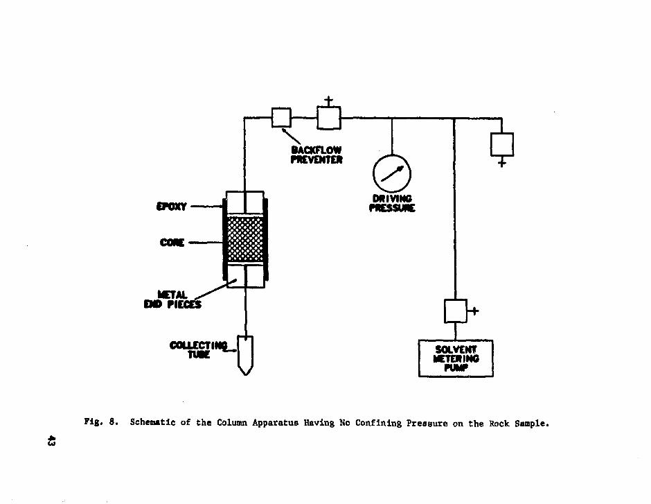
POXY
iACKFLOWPKVEMTE*
SOLVCNTMETERING
PUMP
Fig, 8. Schematic of the Column Apparatus Having No Confining Pressure on the Rock Sample.

Laboratory radionuclide transport experiments on a larger scale are
described in Sec. IV.H.
This work element, when combined with the others identified above, is a
principal input to Sec. IV.P, "Experiment Analysis," and defines and evaluates
many of the expressions and parameters which must be included in the mathe-
matical models in order to predict system behavior and analyze experimental
results.
M. Laboratory and Field Fracture Flow Tests
Prototypes of the WATIS and WCAMPSS will be tested in transparent pipes
in the laboratory. A more elaborate system using a full-scale artificial
fracture fabricated from clear lucite is being evaluated. In this scheme,
water containing dyes would be used to observe the behavior of the total
system.
Following successful operation in the laboratory, a limited, near-wall
fracture flow test is planned in the field to test the system emplacement and
to develop operating procedures for the "cold" experiment (Sec. IV.N). A
limited mine back is planned for evaluation of both the operation of the
system and flow-path detection procedures (Sec. IV.I). The mine/core back
operation will also help develop the procedures for similar operation in the
migration experiments (Sees. IV.N and IV.0). Based on the results of these
tests, final design changes, if any, will be made to the injection and collec-
tion systems and fabrication of the units for the "cold" experiment will
commence.
N. First ("Cold") Field Experiment
A full-scale mock-up of the radionuclide migration experiment will be
performed in the selected site in 6-tunnel (Sec. IV.A) using stable tracers
(Sec. IV.D). It is possible that short-lived radionuclides can also be used
if the mining and coring techniques (Sec. IV.B) are considered safe. This
experiment will test the experimental design and the safe handling procedures
developed for the use of radioactive tracers. The secondary water movement
tracer, developed earlier (Sec. IV.G), will be used. Tritrated water may
also be employed as a check on the behavior of the secondary water movement
tracer. If the technology for studying colloid migration is sufficiently
well developed (Sec. IV.L), then studies of this type will also be performed.
Post-experiment analysis of the flow path (Sec. IV.L) will be done. The
44

results will be compared with Models, which will be updated as necessary
(Sec. IV.P).
Prior to initiation of the field experiment, a detailed engineering test
plan will be written. The parameters for this test will have been developed
earlier. Many of the methods and procedures used to perform the experiment
will have been developed and documented in the earlier stages of the project:
site selection (Sec. IV.A); detailed site characterization (Sec. IV.B);
groundwater characterization and selection (Sec. IV.C); isotope selection
(Sec. IV.D); construction of the experimental area and development of instru-
mentation (Sec. IV.F); development of water and tracer injection systems
(Sec. IV.J); development of the multipoint water sampling system (Sec. IV.K);
development of the methods for post-experiment analysis of the flow path, and
optimization of the requirements from the chemical interaction studies (Sec.
IV.L).
The actual configuration of the migration experiment cannot be given
until the site is selected and detailed characterization is completed.
Possible configurations for experiments using a horizontal or a vertical flow
path are given in Figs. 9 and 10, respectively. The maximum length of the
flow path will be less than 1.5 m. Prior to injection of the tracers, ground-
water will be injected for some time in order to fully saturate the rock and
establish steady state flow. The elements to be studied will then be injected
from a single point since this will allow data to be obtained on dispersion
along the flow path.
Of primary concern is the necessity for control of the water residence
time in the fracture so that rates reasonably representative of natural
systems can be utilized. The flow rate will be optimized so that maximum
information is obtained from the experiment. The need to control the time in
the field measurements is due to the possibility of having kinetic effects.
That is, the kinetics of the adsorption and desorption processes may be
important if the flow rates are too high. Obviously, this is also true in
the laboratory studies (Sec. IV.L) and the kinetic information will be obtained
using laboratory techniques. It has been shown that kinetic effects are
not important if the time for solvent flow over tire experiment flow path is
significantly greater than the half-time for sorptlon. In essence, this
means that for a real repository, where far-field flow paths are several
kilometers long and flow rates are less than 100 m/y kinetic effects will
45

TRACER INJECTION HOLE
COLLEI
WATER INJECTIONHOLEHORIZONTAL FRACTUREPLANE
Fig. 9. Possible Experiment Configuration for a Horizontal Flow Path.

WATER MJECTION HOLES
TRACER INJECTION HOLE
COLLECTION HOLES
VERTICAL FRACTURE PLANE
Fig. 10. Possible Experiment Configuration for a Vertical Flow Path.
47

probably be neglectable. However, in these experiments, one wishes to have a
minimal contribution from kinetics (i.e., reasonably chroaotographic behavior)
since it will be much simpler to interpret the field experiments if significant
kinetic effects are absent.
In order to gain information in a single experiment on a variety of ele-
ments having greatly differing retardation properties, "staged" injections of
water movement tracer and migrating element(s) may be used. That is, several
injections of groundwater containing one or more tracers would be made at
different times during the course of the experiment. The earliest injections
would be for those elements with the lowest migration rates, while later
injections would be for the elements having higher migration rates. The
concentration of the migrating element in the groundwater will always be
significantly below the solutiliby limit in that water. The length of the
injection period will be optimized in the laboratory studies. The migration
rate information used to select the sequence of injection would also be
obtained from the laboratory studies. This procedure would localize most of
the migrating elements somewhere along the flow path and would give the maxi-
mum time for migration of those elements with strong retardation characteristics.
A mass balance would be attempted for all tracers used in the study.
The total duration of the experiment, from initiation to termination of
groundwater flow, will be about 18 weeks. This will then be followed by
application of the post-experiment analysis methods (Sec. IV.I) to the actual
flow path, which will be removed using techniques described in Sec. IV.B.
The results from this experiment will then be interpreted as described
in Sec. IV.P.
0. Second ("hot") Field Experiment
Since the transport of actinides by groundwater is of major concern, a
field experiment will be performed to determine their potential for migration
under natural conditions. This experiment will also address the reproduci-
bility of field experiments since some of the same elements used in the
"cold" test (Sec. IV.N) will be used.
The same basic operations will be used for this experiment as for the
"cold" experiment (Sec. IV.N). Based on information from the "cold" experi-
ment, the earlier experimental plan will be revised as necessary in prepara-
tion for the first "hot", actinide containing, experiment. The water moveaent
tracer will be either tritiated water (HTO) or the secondary water moveaent
48

tracer (Sec. IV.6) used earlier. Generally, the same elements (now radioactive)
utilized in the "cold" test will be used with the addition of several actinides
(Sec. IV.D). This experiment will be carried out in a new area at the saae
site. After removal of the residual workings of the "cold" experiment (Sec.
IV.N), a portion of the sane fracture farther in from the tunnel wall or
farther down in the sane drift will be used.
The duration of the flow portion of the experiment will be about 22
weeks, the length of the flow path will be less than 1.5 m, the post-test
analysis of the flow path will be done, and comparison of the results with
state-of-the-art models will be made. These models will have been updated by
the results from the "cold" (Sec. IV.N) test. The applicability of these
models to actinide transport will then be addressed.
P. Experiment Analysis
The objective of this work element is to identify, assemble, and imple-
ment the mathematical analyses required to: 1) interpret the results from
the laboratory experiments (Sec. IV.L); 2) provide residence-time-distribution
analyses of water movement tracers in order to define migration paths (Sec.
IV.L, IV.N, and IV.0); 3) conduct pretest radionuclide transport analyses as
required for experiment design (Sec. IV.N, IV.0, and VI); and 4) interpret
results from the bench-scale experiments (Sec. IV.H) and from the "cold"
(Sec. IV.N) and "hot" (Sec. IV.0) field experiments, and identify deficiencies
in current radionuclde transport models (Sec. VI). Currently available
experimental techniques, methods of data analysis, and radionuclide transport
models (Sec. VI), or reasonable modifications thereof, will be utilized
whenever possible. Available literature data will also be employed. The
principal types of analyses which must be implemented in order to achieve the
above objective are discussed below.
Equations are inquired which describe the batch, tablet, and whole-core
radionuclide sorptior and chemical reaction rate studies (Sec. IV.L). As
necessary, such equations will include terms for sorption and reaction equi-
libria and mechanisms, molecular diffusion into the immobile phase (rock), and
kinetic expressions for homogeneous and heterogeneous chemical reactions such
as those producing polymers, colloids, precipitates, changes in oxidation
states, and complexes with constituents of the rock and groundwater. The
equations describing transport of radionuclides as particulates suspended in
49

the groundwater aust be included. The particulates could be either radiocol-
loids or naturally occurring particles which sorb radionuclides.
Equations are required which describe the residence-tiae distribution of
water aoveaent tracers. These would include equations for ideal flow systeas
and various solute source teras (such as step increase, square wave, etc.).
Since "ideal" fractures will not be used in the aajority of the studies,
particularly in the field, the appropriate equations will be modified to
account for the non-ideal conditions (e.g., Ref. 37).
Comprehensive models are required which describe radionuclide transport
in the selected fractures and surrounding rock. Such models aust incorporate
expressions describing the pertinent cheaical phenoaena controlling radio-
nuclide transport as described above and, as appropriate, expressions re-
flecting the results of the residence-tiae-distribution analyses for the
water movement tracers. Existing techniques will be used to interpret the
results from the bench-scale (Sec. IV.H), "cold" (Sec. IV.N) and "hot" (Sec.
IV.0) experiments and will also be used for pretest analyses in order to
determine the experimental conditions (flow rate, radionuclide concentrations
etc.) to be used in those experiments. The chemical paraaeters doainating
radionuclide transport models will be evaluated using aethods such that the
parameter values are directly related to specific laboratory aeasureaents
(Sec. IV.L) which describe fundamental processes (such as diffusion, first-
order homogeneous chemical reactions, etc.).
The data from the bench-scale and field experiments will be coapared
with analogous data calculated using the available mathematical aodels. The
adequacy of the models and laboratory techniques used to evaluate parameters
will thereby be assessed. Refineaents to the aodels and laboratory techniques
will be made as necessary, and paraaeter values will be continuously refined
using established parameter estimation techniques (e.g., Ref. 56).
The field experiaents and accoapanying analyses will provide the data
and aeans to evaluate the adequacy of NWTS aodels under realistic conditions
and, where appropriate, will provide a supplementary data capability. The
adequacy of the available data base of chemical parameters will also be
exaained.
The data froa the field experiaents will be made available on a tiaely
basis to the NWTS modeling community (Sec. VI). This will allow independent
interpretation of the experiaental results.
50

V. TECHNICAL APPROACH
The organization of all of the various prograa activities described in
Sec. IV into a logical sequence of interrelated events needed to achieve the
project objectives is shown in detail in Figs. 11-13. These detailed logic
networks identify the estimated tiae (in weeks) for a given activity and show
the interrelationships between the work elements. A description of the elements
on the network charts is given in Appendix C. The tiae estimates are not coamit-
aents but do reflect our current projections of the tiae required. Of necessity,
the tiae estimates are less precise when they are far in the future. The aajor
milestones are summarized in Sec. VII. The logic networks will be updated per-
iodically as more accurate projections becoae available.
As indicated, peer reviews will be held, at a ainiaua, at the major
critical points in the project. Indeed, the tiae for the review process seens
to be a aajor factor in the length of the project. The impact of these peer
reviews is discussed in Sec. X.
VI. PROGRAM INTERFACES
The field experiments described in this program plan are an integral
part of the national (NWTS) program to describe nuclide transport in geologic
systems. As such, the knowledge gained by this effort must interface with
existing NWTS programs. A diagram of these interfaces is given in Fig. 14.
When applicable, the laboratory methods developed by the Waste-Rock
Interactions Technology (WRIT) program at Battelle Pacific Northwest Labora-
tories (BPNL) under R. J. Serne will be integrated witk this project. This
is already being accomplished since Los Alamos is a WRIT subcontractor.
Developments in experimental techniques and transport phenoaena will be trans-
mitted to the WRIT program. The field experiaent effort will also define soae
measurement needs which aust be factored into the WRIT prograa. Saaples of the
material from G-tunnel will be sent to the WRIT project for use in that program.
The other aajor interface to NWTS efforts is to the Waste Isolation Per-
formance Assessaent Program (WIPAP) under H. C. Burkholder at ONWI. The
principal goal of this program is to evaluate the perforaance of geologic
repository concepts, priaarily by modeling efforts. The three WIPAP aodeling
subeleaents are 1) the Systematic Comprehensive Evaluation of Perforaance and
Total Effectiveness of Repositories (SCEPTER), 2) the Assessaent of the
Effectiveness of Geologic Isolation Systems (AEGIS), and 3) a prograa at the
51

U
IV
u•H00
aV
u
oo-H
52

•—H
I
fj,
i
III
i
III
uo3
u•rl
o4V
eo•H
53

in
NM REPORTCOMPLETE
-MM
HOCLIOE MKRATIONFIELD EXPERIMENT
Fig. 13. Part 3 of the Logic Network.

WASTE-ROCKINTERACTIONTECHNOLOGY
PNl(SUBCONTRACTORS)
LAB. MEASUREMENTS
MEASUREMENT NEEDS
FIELD EXPERIMENTS
TUFF: LASL/SNL/ANLGRANITE: LLL
WASTE ISOLATIONPERFORMANCEASSESSMENT
PROGRAM
SCEPTER (INTERA)AEGIS TPNL)
UCB
Fig . 14. In t e r f aces t o SWTS Program in Nuclide Transpor t .
Univers i ty of Cal i forn ia a t Berkeley (UCB). These programs a r e being p e r -
formed under the d i r e c t i o n of the fol lowing:
SCEPTER R. B. Lantz (Intera, Inc.)
AEGIS F . H. Dove (BPNL)
UCB T. H. P i g f o r d (UCB)
The modeling efforts being conducted as part of WIPAP will be integratedwith this field experiment project. The applicable WIPAP models will be usedto predict the experimental results for the bench-scale experiments and fieldexperiments, provided that the directives for these calculations are given
55

from ONWI/WIPAP. Sufficient funds are not available in this field experiment
project to support calculational activities by WIPAP participants. It
does seem, however, that few of the WIPAP models currently include elements
that describe the chemistry that occurs when radionuclides are introduced
into a groundwatar-geologic media environment. Also these models are primarily
regional in nature and thus may not be applicable for predicting transport in
geometrically simple, single fractures. The possible model deficiencies
identified in the experimental program will be communicated to the WIPAP
participants, as will possible methods of correction. These interactions
should create the necessary dialogue between experimenters and modelers.
This project will also be coordinated with the studies being carried out
in the NNWSI project. Extensive studies of the properties of tuff in other
areas at the NTS which may have bearing on the field studies are being obtained
in the NNWSI. The Los Alamos and SNL are already involved in the NNWSI.
As indicated in Sec. IV.I, J. L. Means at the Battelle Columbus Laboratory,
Columbus, Ohio, will perform analyses of the total organic content of the
groundwater and solids used in the studies.
As indicated in Fig. 14, a nuclide migration field test in granite is
being performed by the Lawrence Livermore National Laboratory (LLNL). Since
Los Alamos, SNL, and LLL are all participants in the NNWSI and both the field
projects are considered tasks within the NNWSI, the Nevada project will serve
as the formal mechanism for cooperation and exchange of information between the
two efforts.
VII. SCHEDULE/MAJOR MILESTONES
The key milestones of this project are described in Table III. From the
start of the project to completion of the experiments, the critical path,
based on current projections, may be summarized as follows (assuming minimal
field or laboratory work in FY-1980):
Technology development and laboratory studies 19 months
"Cold" Field Experiment 16 months
"Hot" Field Experiment 13 Months
Project Summary 9 Months
These estimates include the time for the review process and for preparation
of documents.
56

TABLE III
MAJOR MILESTONE DESCRIPTION
Number Date Node"
1
2
3
4
5
6
7
8
9
10
11
5/16/80
8/80
9/80
9/80
6/81
5/82
5/82
9/83
9/83
10/83
3/85
8320
8340
8314
8355
8446
8525
8527
8570
8565
8567
8605
See Sec. VII, Figs. 11-13.
Title
Availability of Funds.
Complete the Peer Review of the DraftProgram Plan.
Transmit the Project Quality AssurancePlans to 0NWI.
Transmit the Final Program Plan to NVand 0NWI.
Complete the Summary Site SelectionLetter Report.
Complete the Experimental Test Plan forthe "Cold" Field Experiment.
Complete the Peer Review of ExperimentPlan for the "Cold" Experiment.
Complete the "Cold" Experiment DraftReport.
Complete the Revision of the Experi-mental Plan for the "Hot" Experiment.
Complete the Peer Review of the RevisedExperimental Plan for the "Hot" Experiment.
Complete Preparation of ComprehensiveNuclide Migration Field ExperiaentsReport.
VIII. BUDGET
The funding from the Department of Energy, Office of Waste Isolation,
needed to achieve the goals of this program according to the schedule given in
Sec. VI is given in Table IV by fiscal year (FY) and by organization. The
values include an 8% per year inflation factor. The funding level given in
Table IV has little contingency for uncertainties and a aajor uncertainty is the
true inflation rate. The actual schedule of the various activities is also
57

TABLE IV
ESTIMATED BUDGET REQUIREMENTS ($1000)
FY
1980
1981
1982
1983
1984
1985
TYPE
0C
0C
0C
0C
0C
0C
LASL
790
326195
459100
486100
5080
300
SNL
800
507213
586100
558100
5500
150
ANL
300
23194
22422
18525
2130
150
NTSSO
610
1580
1910
1400
1630
00
Tota
2500
1222502
1460222
1369225
14340
600
0 indicates operating costs; C indicates capital equipment costs.
rather uncertain since the schedule (Sec. V) goes so far into the future.
Also, events beyond our control may make the availability of support personnel
and equipment uncertain due to programmatic commitments at the NTS. Unknown
difficulties in the field operations themselves can severely impact program
activities.
Included in the budget given in Table IV is about $50K per year for
Quality Assurance (QA). This low figure comes about because existing QA Pro-
gram Plans have been developed and implemented as part of the NNWSI; the
NNWSI QA plans will be used for this project.
A listing of the capital equipment needs that have been currently iden-
tified for this project for FY-1981 is given in Table V. Additional items
undoubtedly will be needed as the project develops. The items of equipment
listed are especially important since they will be required throughout the
entire course of this program and must be ordered early because of long
delivery times. The ability to meet the projected milestones depends criti-
cally on timely acquisition of this equipment.
IX. TECHNICAL CONTROL
This program will be treated as a generic ta*.k within the NNWSI project
of the Nevada Operations (NV) Office of the Department of Energy (DOE). The
58

TABLE V
FY-1981 CAPITAL EQUIPMENT NEEDS
Estimated CostLos Alamos Scientific Laboratory ($1000)1. Radioactive flow monitor 102. Process controller 203. Controlled-atmosphere enclosure and accessories 304. Gas chromatograph and electron capture detector 205. Water preconcentrator 106. Solvent delivery and pressure pumps 207. UV/VIS spectrophotometer 208. Data reduction equipment 209. Pulse-height analyzer and electronics 2510. Vibrating-reed electrometers 1011. Hall probe - Gauss meter 10
Subtotal 195
Sandia National Laboratory
1. Flow meter and electronics 22. Centrifugal pump, valves, etc. 53. Pulse-height analyzer 154. RTV packers (design & manufacture 20 packers) 1005. Injection packers (design & manufacture 3 packers) 306. Flow meters (15) 87. pH probes 38. Eh probes (developmental) 209. Data acquistion system additions and upgrading 30
Subtotal 213
Argonne National Laboratory
1. Cyclotron target holder assemblies 252. Vacuum centrifugal concentrators 63. High-pressure, controlled volume pumps 34. Electronic modules 45. Gas chromatograph 86. Pressurized column holders 57. Computer interface 158. Remote processing equipment 109. Process monitoring and fluorescence analysis electronics 1510. Miscellaneous 3
Subtotal 94
Total 502
59

Los Alamos will be the project coordinator and will represent ANL in the NNWSI
program. R. M. Nelson, director of the Waste Management Program Office (WMPO),
is the principal contact at NV.
The actual technical direction of the program will be done through a
Steering Conmittee which has representatives from the three laboratories
involved. All laboratories have equal responsibility. The members of this
committee are:
Los Alamos Bruce R. Erdal
SNL J. Keith Johnstone
ANL Arnold M. Friedman
The Los Alamos is the principal contact and spokesman for this effort and will
coordinate the efforts. Th^ steering committee is also responsible for review
of technica.1 documents prior to delivery to technical review system at each
laboratory.
Quality Assurance (QA) procedures and practices will be followed in the
execution of this project. The QA Program Plan (QAPP) developed at LASL and
SNL for the NNWSI project will be used for this project. The ANL QAPP is
similar. All these plans will be forwarded for approval by WMPO/NV.
Weekly telephone reports of project activities and accomplishments by
each of the laboratories will be made to LASL and these will then be trans-
mitted to WMPO/NV. This will mean at least weekly communication between the
project participants and discussion of project needs and activities.
The main areas of responsibility for the activities are:
All: Field experiment designLaboratory studiesBench-scale studiesAnalytical support
Los Alamos: Project coordinationMaterials characterizationWater movement tracersPost-experiment analysis
SNL: Field experiment operationsWater and tracer injection system design and fabricationWater collection and sampling system design and fabrication
ANL: Isotope productionFlow path analysis methods
Obviously, certain aspects of the program must be carefully coordinated since
similar capabilities and interests sometimes exist in each laboratory. The
60

actual organization performing a certain task will depend on the availability
of manpower when the other work elements of the program are taken into account.
Also, each organization can contribute to the various areas of responsibity
mentioned above. They are not exclusive. All data transferred between project
participants will be entered into the QA document control system. This will
ensure traceability of the information through the QA procedures implemented in
each organization.
The SNL will direct all field operations within G-tunnel.
X. PROGRAM CONTROL
Several decision points have been identified in the project (Sees. V and
VIII). A peer review will be scheduled at these points. The peer reviewers
will be selected by WMPO/NV, and programmatic reviewers will be selected by ONWI.
These peer reviews will document any project deficiencies and will be the
basis for any external recommendations for changes in the project definition.
Approval of such changes will be made through WMPO/NV.
Two different reports will be routinely generated in addition to the
weekly telephone reports mentioned in Sec. IX. A monthly status report will
be delivered to WMPO/NV by the middle of the month following the close of the
report month. This will also include the actual costs for the report month
and a status report on the milestone schedule. Quarterly technical reports on
the project accomplishments will also be issued. Topical reports will be issued
as needed and as designated in the project milestone list (Sec. VII). Similarly,
publications in the open literature and presentations at major technical
meetings will be made when appropriate. All of these reports and documents will
go through the technical review processes at each laboratory as described in
the QA Program Plans at each laboratory. The WMPO/NV will also review them for
policy purposes.
Three engineering test plans, as identified in the milestone list (Sec.
VII), will be generated. A safoty analysis document will be delivered to
DOE/NV, as required by DOE Order 5481.1, prior to initiation of any field
experiment employing radioactivity.
REFERENCES
1. G. M. Fairer and D. R. Townsend, "Geologic Investigations" in "U.S. GeologicSurvey Investigations in Connection with the Mighty Epic Event, U12n.lOTunnel, Nevada Test Site," U. S. Geol. Surv. report USGS-474-228 (1975).
61

2. W. Thordarson, "Perched Ground Water in Zeolitized-Bedded Tuff, RainierMesa and Vicinity, Nevada Test Site," U. S. Geol. Surv. Open-File reportTEI-803 (1965).
3. L. V. Benson, "Mass Transport in Vitric Tuffs of Rainier Mesa, Nye County,Nevada," Desert Research Institute report NVO-1253-10 (1976).
4. W. Vollendorf, Sandia National Laboratories, personal communication, 1980.
5. J. K. Johnstone and K. Wolfsberg, Eds., "Evaluation of Tuff as a Mediumfor a Nuclear Waste Repository: Interim Status Report on the Propertiesof Tuff," Sandia National Laboratories report SAND80-1464 (1980).
6. H. C. Claassen and A. F. White, "Application of Geochemistry Kinetic Datato Groundwater Systems. A Tuffaceous-Rock System in Southern Nevada," inChemical Modeling in Aqueous Systems, E. A. Jenne, Ed. (American ChemicalSociety, Washington, 1979).
7. B. R. Erdal, Ed., "Laboratory Studies of Radionuclide DistributionsBetween Selected Groundwaters and Geologic Media, April 1 - June 30, 1980,"Los Alamos National Laboratory report LA-8472-PR (1980).
8. D. G. Coles, Lawrence Livemore National Laboratory, personal communica-tion, 1980.
9. H. C. Claasen, "Water Quality and Physical Characteristics of NevadaTest Site Water Supply Wells," U. S. Geol. Surv. report USGS-474-158(NTS-242) (1973).
10. E. N. Vine, R. D. Aguilar, B. P. Bayhurst, W. R. Daniels, S. J. DeVilliers,B. R. Erdal, F. 0. Lawrence, S. Maestas, P. Q. Oliver, J. X,. Thompson, andK. Wolfsberg, "Sorption-Desorption Studies on Tuff, II. A Continuation ofStudies with Samples from Jackass Flats, Nevada and Initial Studies withSamples from Yucca Mountain, Nevada," Los Alamos National Laboratoryreport LA-8110-MS (1980).
11. I. Neretnieks, Royal Institute of Technology, Stockholm, Sweden, personalcommunication, September, 1979.
12. S. N. Davis, G. M. Thompson, H. W. Bentley, and G. Stiles," Ground-WaterTracers - A Short Review," Ground Water 18, 14 (1980).
13. C. C. Cory and J. H. Horton, "Movement of Water Tagged with 2H, 3H, and1 80 Through Kaolinitic Soil," Soil Sci. Soc. Am. Proc. 32, 471 (1968).
14. R. E. Greene, "Tracing with Activable Tracers: Part II," Isot. and Radiat.Techn. 6, 70 (1968).
15. H. P. Taylor, Jr., "Oxygen Isotope Studies of Hydrothermal Mineral Deposits,"in Geochemistry of Hydrothermal Deposits, H. L. Barnes, Ed., (Holt, Rinehart,and Winston, Inc., New York), 1967, pp. 109-142.
16. W. J. Kaufman and G. T. Orlob, "An Evaluation of Ground-Water Tracers,"Trans. An. Geophys. Union 37, 297 (1956).
62

17. E. N. Vine and B. P. Bayhurst. "Crushed Rock Columns, a Comparison withBatch Measurements," in "Research and Development Related to the NevadaNuclear Waste Storage Investigations, January 1 - March 31, 1980,"B. M. Crowe, Compiler, Los Alamos National Laboratory report LA-8419-PR(1980).
18. D. K. Cassel, M. Th. Van Genuchten, and P. J. Wierenga, "PredictingAnion Movement in Disturbed and Undisturbed Soils," Soil Sci. Soc. Am.Proc. 39, 1015 (1975).
19. G. W. Thomas and A. R. Swoboda, "Anion Exchange Effects on Chloride Move-ment in Soils," Soil Sci. 110, 163 (1970).
20. D. I. Leap and R. J. Sun, "Iodide- and Bromide-Tracer Studies in CarbonateRocks," in Geological Survey Research 1978, U. S. Geol. Surv. Prof. Paper1100 (1978), p. 223.
21. K. Wolfsberg, B. P. Bayhurst, B. M. Crowe, W. R. Daniels, B. R. Erdal,F. 0. Lawrence, A. E. Norris, and J. R. Smyth, "Sorption-DesorptionStudies on Tuff, I. Initial Studies with Samples from the J-13 DrillSite, Jackass Flats, Nevada," Los Alamos National Laboratory reportLA-7480-MS (1979).
22. W. A. Jester, R. C. Raupach, F. G. Huster, "A Comparison of Bromide IonNeutron Activatable Tracer and Tritiated Water as Groundwater Tracers,"in Proceedings of the Third International Conference on Nuclear Methodsin Environmental and Energy Research, Columbia, Mo. (CONF-771072) (1977).
23. W. A. Jester, and K. A. Uhler, "Identification and Evaluation of WaterTracers Amenable to Post-Sampling Neutron Activation Analysis." ResearchPublication No. 85, The Pennsylvania State University Institute forResearch on Land and Water Resources (1974).
24. F. G. Haaser, W. A. Jester, and W. R. Heald, "Use of Neutron ActivatableTracers for Simulating Water and Chemical Flow Through Porous Media,"Research Project Technical Completion Report, The Pennsylvania StateUniversity Institute for Research on Land and Water Resources (1978).
25. Z. B. Alfassi and L. Feldman, "The Preparation of Carrier-Free Radiobromine:The Separation of KBrO3 and KBr Using an Organic Solvent," Int. J. Appl.Rad. and Isotopes 27, 125 (1976).
26. P. L. Smart and I. M. S. Laidlaw, "An Evaluation of Some FluorescentDyes for Water Tracing," Water Resour. Res. 13, 15 (1977).
27. U. Omoti and A. Wild, "Use of Fluorescent Dyes to Mark Pathways of SoluteMovement Through Soils Under Leaching Conditions: 2. Field Experiments,"Soil Sci. 128, 98 (1979).
28. J. C. Corey, "Evolution of Dyes for Tracing Water Movement in Acid Soils,"Soil Sci. 106, 182 (1968).
29. G. H. Cook, "Chemical Properties11 in Argon, Helium, and The Rare Gates,G. H. Cook, Ed. (New York, Interscience Publishers, 1961), pp. 157-172.
63

30. D. C. Hoffman, R. Stone, W. H. Dudley, Jr., "Radioactivity in the Under-ground Environment of the Cambric Nuclear Explosion at the Nevada TestSite," Los Alamos National laboratory report LA-6877-MS (1977).
31. P. G. Guthals and M. M. Fowler, Eds., "Heavy Methanes (Mass-20 and -21)as Atomspheric Tracers," los Alamos National Laboratory report LA-7321-MS(1978).
32. E. H. Essington, "Evaluation and Selection of Tracers for Field Measure-ments of Coefficient of Dispersion," Teledyne Isotopes report NVO-1229-176(1971).
33. W. W. Wood and G. G. Ehrlich, "Use of Baker's Yeast to Trace MicrobialMovement in Ground Water," Ground Water 16, 398 (1978).
34. J. G. Vecchioli, G. G. Ehrlich, and T. A. Ehlke, "Travel of PollutionIndicator Bacteria Through the Magothy Aquifer," U. S. Geol. Surv. Prof.Paper 800-B, B237 (1972).
35. R. Martin and A. Thomas, "An Example of the Use of Bacteriophage as aGroundwater Tracer," J. Hydrology 23, 73 (1974).
36. D. D. Gonzales, Sandia National Laboratories, personal communication, May1980; H. W. Bentley, University of Arizona, personal communication, July1980.
37. P. A. Witherspoon, J. S. Y. Wang, K. Iwai, and J. E. Gale, "Validity ofCubic Law for Fluid Flow in a Deformable Rock Fracture," Lawrence BerkeleyLaboratory report LBL-9557 (1979).
38. W. W. Meinke, "Trace-Element Sensitivity," Science 121, 177-184 (1955).
39. J. Lerner, Argonne National Laboratory, personal communication, July, 1980.
40. C. N. Davids, "X-ray from Proton Bombardment of Monazite Salts," Proceedingsof Workshop on Search for Superheavy Eements, Tallahasse, Florida, Sep-tember 29-0ctober 1, 1979.
41. C. J. Sparks, "Search with Synchrotron Radiation for Superheavy Elements inGiant Halo Inclusions," Phys. Rev. Lett. 38, 205 (1977).
42. A. C. Wahl and W. R. Daniels, "Emanating Power of Barium Stearate for3.9-sec Actinon (219Rn)," J. Inorg. Nucl. Chem. 6, 278 (1958).
43. B. R. Erdal, Ed., "Laboratory Studies of Radin-mclide Distributions BetweenSelected Groundwaters and Geologic Media October 1, 1978 - September 30,1979 Annual Report," Los Alamos National Laboratory report LA-8088-PR(1980).
44. J. M. Cleveland, The Chemistry of Plutonium (American Nuclear Society,La Grange Park, IL, 197S).
45. J. L. Thompson and K. Wolfsberg, "Applicability of Microautoradiography toSorption Studies," Los Alamos National Laboratory report LA-7609-MS (1979).
64

46. E. L. Cussler, Multicomponent Diffusion (Elsevier, Amsterdam, 1976).
47. K. L. Erickson, "Preliminary Rate Expressions for Analysis of Radio-nuclide Migration Resulting from Fluid Flow Through Jointed Media,"Scientific Basis for Nuclear Waste Management, Vol. 2, C. J. Northrup,Ed. (Plenum Press, New York, 1980) (in press).
48. K. L. Erickson, "A Fundamental Approach to the Analysis of RadioauclideTransport Resulting from Fluid Flow Through Jointed Media," Sandia NationalLaboratories report SAND80-0457 (1980, to be published).
49. F. Helfferich, Ion Exchange (McGraw-Hill, New York, 1962).
50. J. Rosen, "Kinetics of a Fixed-Bed System for Solid Diffusion intoSpherical Particles," J. Chem. Phys. 37, 387 (1952).
51. J. Rosen, "General Numerical Solution for Solid Diffusion in Fixed Beds,"Ind. Engr. Chem. 46, 1590 (1954).
52. A. M. Friedman and S. Fried, "Kinetic Effects in Migration," RadioactiveWaste in Geologic Storage, S. Fried., Ed., ACS Symposium Series 100 (Am.Chem. Soc, Washington, D.C., 1979), p. 191.
53. S. Fried, A. Friedman, F. Schreiner, R. Sjoblom, J. Hines, R. Strickert,and P. Rickert, "Measurements of Parameters Essential to Predicting NuclideMigration," Scientific Basis for Nuclide Waste Management, Vol. 1, G. J.McCarthy, Ed. (Plenum, N.Y., 1979), p. 367.
54. M. G. Seitz, P. G. Rickert, S. Fried, A. M. Friedman, and M. J. Steinder,"Migratory Properties of Some Nuclear Waste Elements in Geological Media,"Nucl. Tech. 44, 284 (1979).
55. E. Glueckauf, "Applicability of the Theoretical Plate Theory," Trans.Faraday Soc. 51 (385), Sec. 34-44, p. 1 (1955).
56. J. V. Beck and K. J. Arnold, Parameter Estimation in Engineering andScience (J. Wiley & Sons, New York, 1977).
APPENDIX A
GENERAL DESCRIPTION OF TUFFa
Tuff is a geological term for rocks composed principally of compacted
volcaniclastic material. Such rocks may be deposited either directly by
explosive volcanic events, or they may be reworked and redeposited by surface
processes. Because silicic (e.g., rhyolitic) volcanism tends to be more
aTaken from Ref. 1.
65

explosive than the eruption of more mafic magmas, silicic tuff tends to be much
morevoluminous and widespread than basaltic tuff despite the much greater volumes
of basaltic volcanic rocks. In the western United States, particularly in the
Basin-and-Range physiographic province, accumulations of tuff locally exceed
3000 m in thickness, and individual units may be tens of kilometers in lateral
extent.
Eruptions of silicic magmas vary in volume from a few cubic meters to a
massive catastrophic event depositing hundreds of cubic kilometers of ash and
lava in a single eruption. On eruption, silicic magmas most commonly contain
<10% primary crystals (phenocrysts) and incorporate <10% lithic fragments, so
that generally >80% of the material deposited is glass. Eruption may occur as
a relatively small quiescent fiow of very viscous lava that commonly quenches
to form an obsidian. However, in large eruptions the great majority of material
is ejected explosively as fine ash, shards, and pumice because of the high
viscosity and high volatile content of silicic magmas.
Large explosive eruptions commonly begin with ejection of pumice, shards,
and ash that are deposited downwind of the vent as a cool unscrted layer of
low-density material termed an air-fall or ash-fall deposit. As eruption
proceeds and increases in intensity, clouds of incandescent ash propelled by
evolving gases are formed over the vent and collapse downslope, depositing
heated material in thick blankets. It is this latter type of deposit that is
volumetrically most significant. As eruption then proceeds, the rocks over-
lying the magma chamber collapse to form a caldera, which may then also fill
with thick sequences of volcaniclastic deposits. Materials deposited above
~500°C will compact and weld by viscous deformation of the glass. Compacted
material that cools rapidly (i.e., weeks to months) may remain glassy, while
that which cools more slowly will crystallize to cristobalite, quartz, and a
mixture of feldspars.
The net result is a complex deposit up to several hundred meters thick
which has cooled as a single unit, and is commonly referred to as a cooling
unit. A schematic cross section through such a deposit is given in Fig. A-l.
Such a deposit commonly has a core of welded material, most of which may
have devitrified (i.e., crystallized) to quartz and feldspar with or without
cristobalite. At the base of the welded zone is a layer of densely welded
material that has not crystallized but remains a dense glass called a
vitrophyre. Welding decreases outward from the core so that the welded zone
66

BULK DENSITY GRAIN DENSITY
1.0 2.0 1.0 2.0 3.0
\
\
)
/
)I
NONWELDED
- -•
PARTIALLY WELDED
WELDED _ _ _ ^ _
[QUARTZ AND FELDSPAR)
j u m t uu 111 n 1111r
^VITROPHYRE
GLASS
- ^
ZEaiTE
^^"""^ -vSTATIC WATER
LEVEL
PROXIMALDISTANCE FROM SOURCE
DISTAL
Fig. A-l. Schematic Cross Section Through an Ash-Flow Tuff CoolingUnit with Typical Bulk and Grain Densities.
is surrounded by zones of material decreasing in density, thermal conductivity,
coherence, and strength. Commonly at the base of the ash-flow deposit is an
unsorted, nonwelded, horizon of loosely aggregated pumice and ash called the
air-fall unit. Because the surface material is also loosely aggregated, it is
readily reworked by surface processes and may be redeposited by streams and
ponds or by volcaniclastic mudflows (lahars). Such processes give rise to
sorted, bedded deposits called bedded tuff.
Because glass is thermodynamically unstable, it commonly alters to various
crystalline phases. At elevated temperatures quartz, cristobalite, and feld-
spars crystallize, as occurs in welded zones. If the porosity is high and water
saturation occurs, glass may alter completely to zeolites in as little as 10000
years even at a temperature below 100°C. If saturation is not achieved, or
if the porosity is low as in vitrophyres, alteration will not occur and the
material may remain glassy for millions of years. There is no evidence that
material once crystallized to quartz and feldspar will later alter to zeolites
under conditions common in these rocks, although feldspars nay alter slowly to
clays, particularly in the presence of acid groundwaters.
67

REFERENCES
1. J. K. Johnstone and K. Wolfsberg, Eds., "Evaluation of Tuff as a Medianfor a Nuclear Waste Repository: Interim Status Report on the Propertiesof Tuff," Sandia National Laboratories report SAND80-1404 (1980).
APPENDIX B
THE ARGONNE 60 in. CYCLOTRON
The products and yields produced at the ANL 60 in. cyclotron are sum-
marized in Table B-I. The yield values are targets containing 100% of the
listed target isotope. For natural elements or compounds, correct accordingly.
The yield per hour depends on the current that can be held on target and the
decay rate of the produced isotope.
Half-life
53.653.6110 m1 1 0 in2.615.021.314.387.237.2
dd
yhhddm
12.42 h162.7 d4.53 d
27.85.62
313 d8.52.7
271 d71.46.2
dt d
hy
dd
Product
7Be7Be18F
18F
22Na24Na
32p35g3S C 1
42K4SCa47Ca5l C r52Mns4Mns2Fe55 F e57Co58Co56 N i
TABLE B-IPRODUCTS AND
Target
7Li7Li160
160
24jjg27A1
32g8
37C136g40Ar45Sc50Tisiv52 C r
52CrS2 C r
55MnseFe56Fe
56 F e
YIELDS
NuclearReaction
(P,n)(d,2n)(a,pn)(3He,p)(d,a)(d,pa)\0f • 2 p j
(d,a)(a,pn)(a,pn)(u,p)(n,a)(d,2n)(d,2n)(a,pn)(3He,3n)(d,2n)(a,p2n)(a,pn)(a,3n)
Yield(MCi/uA-h)
209.4
5,0007,000
1,200-50
10,000~400
•t
1-40
-200-1-50-12.2
24-40
68

TABLE B-I (cont)
PRODUCTS AND YIELDS
Half-life
36.1 h92 y12.75 h9.15 h
243.7 d78.2 h
287 d26.4 h120.4 d56 h35.4 b.34.9 h54.58 h4.58 h
83 d33 d18.66 d64.7 d80 h106.6 d61 d4.3 d41.0 d8.4 d7.48 d2.83 d
115 d60.2 d2.73 y13.1 h4.17 d5.0 y15.2 d15.2 h93.1 d57 h2.2 h8.13 h
21.5 d21.5 d23.9 d19 h70 d38 d
91 h
Product
57Ni63 N i
64Cu62Zn65Zn676a68Ge76As75Se77Br82Br79Br81Rb81Rb83Rb84Rb86Rb8S S r
87y88y9smTc9 6 T c
l06n>Ag
1 1 AAg
1 1 3Sn1 2 4Sb125Sb123j
12 4 l
155Eu
156Eu157Eu168Tmleeyb178Ta
180"^.,178W
178W
187W181Re183Re
184Re186Re
Target
54 F e
63Cu62Ni60 N i
65Cu64Zn66Zn74Ge75As75As80Se79 B r
79 B r
82Kr81Br81Br86 K r
85Rb85Rb85Rb93Nb93Nbi03Rh103Rh
108pd1O9A
x l lCd1 2 2Sn1 2 2Sn122Te
122Te
1 5 4Smls*Sm15*Sm166Er
164Er
181Ta
181Ta
177Hf
176Hf
186W
181Ta
181Tfl181Ta
Re
NuclearReaction
(a in)
(Q»P)(a,pn)(ff,2n)(d,2n)(a»p)(a,2n)(a,pn)(d,2n)(a, 2a)(of.pn)(d,2n)(a,2n)(a,3n)(a,2n)(a,2n)(a,pn)(d,2n)(a,2n)(a,n)(a,2n)(a,n)(a,2n)(a,n)(a,p)(a,2n)(0f,2n)
(a,pn)(a»p)(a,p2n)(a,pn)(a,p2n)
(a,p)(of,pn)(a,2n)(3He,ff2n)(3He,a)(a,3n)(0f,2n)(3He,2p)(a,4n)(ff,2n)(0(,n)(%e,2p)(3He,a)
Yield(MCi/MA-h)
8.3?
-400167-4-20
-150-527
-100-500
-1,000-1,000
/v2
-10-10-50-0.5***)-3030-10-5-50***\*u2-0.1250-250.010.8
0.90.5
37C6060—3-330500100.65
10
69

TABLE B-I (cont)
PRODUCTS AMD YIELDS
Half-life
64.1 h23.8 h3.31 h30 y5.01 d10 d5.7 h2.9 y
103 y8.3 h7.2 h
396 d2.85 y2.85 y2.85 y45.6 d45.6 d32.8d
Product
1978H
197mHg209pb
207Bi
2lOBi
206p0
207po
208po
209po
210At
211At235Np236pu
236pu236pu
237pu
237pu
241Cm
ELEMENTS
Target
197Au197Au2O8pb
207pb
209Bi
207pb207pb
209fii
209 B i
209Bi209Bi
235y235U235JJ238JJ235U237Np239Cm
APPENDIX C
IN THE NETWORK
NuclearReaction
(d,2n)(d,2n)(d,p)(d,2n)(d,p)(3He,4n)(3He,3n)(d,3n)(d,2n)(a,3n)(a,2n)(d,2n)(a,3n)(d,n)(d,4n)236Np(a,2n)(d,2n)(a,2n)
CHARTS
Yield(uCi/yA-h)
5001,3009,500
-0.0213010
1,0002.50.06
2,9002,300
0.22-0.05-0.2?
-0.180.150.15
The network charts given in Figs. 11-13 are work-flow diagrams which
include an identification of the activities, the sequence in which they take
place, the assignment of responsibilities, and estimated time needed to per-
form the activity. It is important to emphasize that the network charts are
to be used as a plan in every sense of the word. Because of the uncertainty of
research projects, the plan must have flexibility and be easily changed. The
times given are not commitments, but current estimates of the tine required for
an activity provided the work goes smoothly with only minor delays. As «ore
information becomes available, these time estimates will need to be revised.
For more information on the approach and proper use of network charts, see Ref. 1.
For a brief, but informative discussion of the philosophy and realistic use of
network charts, see Ref. 2.
The various elements shown in the network charts given in Figs. 11-13 are
identified in Fig. C-l. The event numbers are used to identify activities for
computer generated activities and to sho their interrelationship.
70

ACTIVITYDESCRIPTION
START EVENT(ENG'G)
PREPARE INITIAL DESIGN
RESPONSIBLEORGANIZATION
END EVENT
REFERENCES
TIME EST.(WEEKS)
Fig. C-l. Elements of a Network Chart
R. Archibald and R. Villoria, Network-Based Management Systems (PERT/CPM)(John Wiley and Sons, New York, 1968).
M. Becktell, "A Realistic Approach to the Planning of High Technology,High Risk Projects," Sandia National Laboratories report SNAD-1483 (1980).
U.S. OOVERNMENT FBINTINa OFFICC: 1»»1-0-777-0Il/jo